EP0985543A2 - Recyclable recording material containing microparticles - Google Patents
Recyclable recording material containing microparticles Download PDFInfo
- Publication number
- EP0985543A2 EP0985543A2 EP99117810A EP99117810A EP0985543A2 EP 0985543 A2 EP0985543 A2 EP 0985543A2 EP 99117810 A EP99117810 A EP 99117810A EP 99117810 A EP99117810 A EP 99117810A EP 0985543 A2 EP0985543 A2 EP 0985543A2
- Authority
- EP
- European Patent Office
- Prior art keywords
- recording member
- micro
- particles
- surface layer
- recyclable recording
- Prior art date
- Legal status (The legal status is an assumption and is not a legal conclusion. Google has not performed a legal analysis and makes no representation as to the accuracy of the status listed.)
- Granted
Links
Images


Classifications
-
- B—PERFORMING OPERATIONS; TRANSPORTING
- B41—PRINTING; LINING MACHINES; TYPEWRITERS; STAMPS
- B41M—PRINTING, DUPLICATING, MARKING, OR COPYING PROCESSES; COLOUR PRINTING
- B41M7/00—After-treatment of prints, e.g. heating, irradiating, setting of the ink, protection of the printed stock
- B41M7/0009—Obliterating the printed matter; Non-destructive removal of the ink pattern, e.g. for repetitive use of the support
Definitions
- the present invention relates to a recording member which can be repeatedly reused by removing from the recording member inks adhered to the recording member via image formation by a copier, printer and the like. Specifically, the present invention relates to a recording member suitable for use with removing means which use a physical scrubbing force such as a brushing method or the like used with aqueous solvents such as water.
- Japanese Laid-Open Patent Application Nos. HEI 7-311523 and HEI 6-222604 disclose methods for removing images recorded on recording members by forming a swelling layer which swells on contact with moisture on the surface of a recording member, and exposing this swellable layer to water to induce swelling.
- Such a recyclable recording member must have a primary function of being reusable while at the same time providing the demanded performance as a recording member, and this performance must not be diminished after repeated use. Various physical adjustments are required to attain these requirements.
- Japanese Laid-Open Patent Application No. HEI 7-311523 discloses art for adjusting the separation characteristics by regulating the surface roughness of the surface layer within a range of 1 to 30 ⁇ m by adding micro-particles to the resin from equal parts by weight to about double the parts by weight.
- the water-swelling resin used for the aforesaid recording member has a high viscosity, and has a particularly marked viscosity analogous to the recording member at high humidity of 80% and higher. For this reason, when the recording sheets are stacked for storage in a high humidity environment, the viscosity is the same as that of the recording member, which produces a deterioration in handling qualities and characteristics and causes peeling from the recording member.
- the disadvantages arising from a viscosity similar to the recording member are known to be improved by adding the previously mentioned micro-particles so as to reduce the viscosity and improve storage qualities even in a high humidity environment.
- Japanese Laid-Open Patent Application No. HEI 7-311523 discloses a member having a basic function of a recyclable recording member to which the addition of large quantity of micro-particles causes a loss in effectiveness of removing a recorded image.
- an object of the present invention is to provide a recording member having adequate image removing performance in a recyclable recording member from which printing material such as toner can be removed.
- Another object of the present invention is to provide a recording member which does not produce the aforesaid various disadvantages in conjunction with viscosity of recording members even when stored in a high humidity environment.
- the present inventors conducted various investigations to eliminate the aforesaid disadvantages, which resulted in the present invention by discovering that the addition of a specific amount of micro-particles beforehand to the water-swelling surface layer is effective in attaining the aforesaid objects.
- the present invention relates to a recyclable recording member comprising at least a substrate layer and a surface layer, wherein the surface layer includes at least a water-swelling resin component and a micro-particle component, and the micro-particle component content ratio is 1 to 50 parts-by-weight relative to 100 parts-by-weight of water-swelling resin.
- the present invention relates to a recyclable recording member comprising at least a substrate layer and a surface layer, wherein the surface layer includes at least a water-swelling resin component and a micro-particle component, and the micro-particle component has a heat resistance of 170°C or higher.
- the present invention relates to a recyclable recording member comprising at least a substrate layer and a surface layer, wherein the surface layer includes at least a water-swelling resin component and a micro-particle component, and the micro-particle component has particles desirably 1.3 times or greater the thickness of the surface layer.
- the present invention relates to recyclable recording members comprising at least one substrate layer and a surface layer, wherein the surface layer includes at least a water-swelling resin component and a micro-particle component, and the micro-particle component meets any one or more of the features of the above-described embodiments.
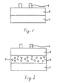
- FIG. 1 illustrates a cross sectional view of a recording member of a first embodiment of the invention.
- the recording member is a lamination of a substrate layer 1 on which is superimposed a surface layer 3.
- FIG. 1 illustrates printing material 4 printed on the surface of the surface layer 3.
- the construction in FIG. 1 has a surface layer 3 formed on one side of the substrate layer 1, the surface layer 3 also may be formed on both side of the substrate layer 1.
- the substrate layer 1 has moisture resistance (strength), and may be a suitable plastic film such as a transparent plastic film or a plastic film which has been rendered non-transparent by adding inorganic micro-particles.
- the material of the plastic film is not particularly restricted, but in consideration of heat resistance and the like, desirable materials include polyester, polycarbonate, polyimide, polymethylmethacrylate and the like.
- desirable materials include polyesters, particularly polyethyleneterephthalate (PET), polyethylenenaphthalate (PEN) and the like. These materials can be used for various types of sheets including overhead projection transparencies (OHP).
- Paper incorporating plastic fibers such as PET fibers and the like, and plastic based papers such as so-called synthetic papers also may be used as the substrate.
- Other usable materials include metal foil, paper having excellent moisture resistance, and complex materials such as resin, paper and metal.
- Other materials may be used insofar as such materials have suitable mechanical strength and moisture resistance, and maintain flatness during printing and removal of the printing material.
- the surface layer formed over the substrate layer comprises a water-swelling resin and micro-particles.
- the incorporation of micro-particles in the surface layer produces a recording member having sufficient image removal characteristics while at the same time providing durability under high humidity conditions and improving sheet transporting characteristics, particularly paper transporting characteristics under high humidity conditions.
- Water-swelling characteristics means the material swells but does not dissolve in water or aqueous solvent.
- a water-swelling resin is formed by cross-linking a water soluble resin. By adding a water insoluble component to a water soluble resin, water or fluid medium can be absorbed to induce swelling without dissolving in the medium.
- water soluble resins examples include water soluble resins having a functional group of active hydrogen in the molecule.
- groups include hydroxy groups, amino groups, amide groups, thio groups, carboxyl groups, sulfonic acid group and the like, such as, for example, polyvinyl alcohol, methyl cellulose, polyacrylate, carboxymethyl cellulose, hydroxyethyl cellulose, polyvinyl pyrrolidone, polyacrylamide and the like.
- polyvinyl alcohol methyl cellulose, and polyacrylate
- polyvinyl alcohol having many hydroxy groups and a degree of polymerization of about 300 to about 3,000, more desirably about 500 to about 2,000, and most desirably about 500 to about 1,700.
- These water soluble resins are desirably used at a rate of about 2 to about 30 parts-by-weight, and more desirably about 5 to about 10 parts-by-weight, relative to 100 parts-by-weight aqueous medium.
- Cross-linking an aqueous resin may be accomplished by employing additives such as cross-linking agents to the aqueous fluid of resin as necessary.
- the cross-linking agent may have a reactivity with the functional group in the aqueous resin molecule, e.g., hydroxy group, amide group, carboxyl group and the like, to cross-link with the aqueous resin.
- useful materials include epoxy compounds, isocyanate compounds, glyoxal, methylol compounds, melamine resin, bicarbonate, aziridine, dihydrazide, and compounds having double bonds such as, for example, diacrylate compounds, dimethacrylate compounds and the like.
- the added amount of cross-linking agent is desirably about 0.1 to about 100 parts-by-weight, and desirably about 1 to about 50 parts-by-weight, relative to 100 parts-by-weight aqueous resin.
- cross-linking agent When not enough cross-linking agent is added, there is inadequate layer strength when swollen, and there is the possibility that the layer will dissolve.
- too much cross-linking agent When too much cross-linking agent is added, the cross-linking agent becomes a bulk component which adversely affects layer strength and the like.
- Inorganic micro-particles and resin micro-particles may be used as the micro-particles added to the surface layer.
- useful inorganic micro-particles include silica, titanium oxide, alumina, zinc oxide, calcium carbonate, magnesium oxide, copper oxide and the like, but usable cross-linking agent is not limited to these. It is most desirable to use silica, alumina, zinc oxide and calcium carbonate. Silica is desirable for its easy dispersion.
- useful resin micro-particles include polymethylmethacrylate, polystyrene, benzoguanamine, phenol, epoxy resin and the like, but usable resin micro-particles are not limited to these.
- the micro-particles added to the surface layer desirably have a secondary size of at least 5 m or more, and at most 50 m or less.
- the secondary particle size is the particle size when individual particles flocculate to form a single flocculant particle. The secondary particle size can be measured by microscopic observation.
- the micro-particles are desirably added at a rate of at least 1 part-per-weight, and at most about 50 parts-by-weight, per 100 parts-by-weight water-swelling resin, and are more desirably added at a rate of at least about 2 part-by-weight, and at most about 30 parts-by-weight, per 100 parts-by-weight water-swelling resin.
- the image When removing an image formed using water-swelling resin, the image is removed using a shearing force on the interface between the image and the recording member to lift the image by swelling, but when the amount of added micro-particles exceeds the range, there may be a lesser degree of swelling due to the reduced percentage of the swellable resin component, which results in less shearing force on the interface and a reduction of the effectiveness of image removal. On the other hand, there may also be inadequate adhesion to the recording member under high humidity conditions.
- Desirable organic micro-particles are resin micro-particles having a heat resistance temperature of about 150°C or higher, and desirably about 170°C or higher.
- Examples of usable materials include polymethyl methacrylate resin, benzoguanamine resin, phenol resin, epoxy resin, and these resin materials cross-linked by well-known cross-linking agents, but the present invention is not limited to these materials. It is desirable to use cross-linked polymethyl methacrylate resin, benzoguanamine resin and the like.
- the effect of the present invention i.e., the effect of improved sheet transportability
- the temperature of the recording member within the apparatus is heated to, for example, approximately 150 to about 180°C via the fixing process, and, therefore, protrusions from the surface of the surface layer of the micro-particles may be difficult to maintain with organic micro-particles which have a heat-resistance of less than about 150°C.
- the heat-resistance temperature is used interchangeably with the melting point temperature.
- the heat-resistance temperature can be measured using a DSC, or melt starting temperature measuring device such as a flow tester.
- inorganic micro-particles and organic micro-particles may be used individually or in combination.
- the size of the micro-particles added to the surface layer is larger than the thickness of the surface layer, and is desirably about 1.3 times or greater the thickness of the surface layer, and more desirably about 1.5 to about 5 times the thickness of the surface layer.
- layer thickness is defined as the thickness of the layer as measured when the surface layer is formed using identical components and constituent quantities but without the addition of the micro-particles to the surface layer.
- the micro-particles protrude from the face of the surface of the surface layer, i.e., part of the micro-particles are visible while the other part is embedded within the surface layer and anchored to the surface layer.
- part of the micro-particle is visible from the surface of the surface layer, and this protruding part suppresses contact with the surface of the surface layer comprising a water-swelling resin having a high viscosity, thereby improving sheet transporting characteristics, and particularly improving sheet transportability by preventing adhesion between sheets when the sheets (recording members) are stacked. That is, when the surface layer is formed on one side of a substrate and the sheets (recording members) are stacked, adhesion between the stacked sheets is prevented because direct contact is effectively suppressed between the surface of the surface layer and the bottom surface of the substrate layer via the protruding part of the micro-particles.
- the surface layer is formed on bilateral surfaces of the substrate layer and the sheets are stacked, adhesion between the stacked sheets is prevented because direct contact is effectively suppressed between the surfaces of the surface layers of the sheets via the protruding part of the micro-particles. Furthermore, since the micro-particles in the present invention are fixedly attached such that part of the micro-particle protrudes from the surface of the surface layer, excellent sheet transporting characteristics, and particularly sheet feeding characteristics, are maintained even with repeated use.
- the size of the micro-particles is less than the thickness of the surface layer, there is a markedly reduced probability that part of the micro-particle will protrude from the surface layer, such that contact with the surface of the surface layer may be difficult to effectively prevent, thereby adversely affecting sheet transportability, particularly sheet feeding characteristics.
- the surface roughness of the surface layer can be adjusted by adding micro-particles of this size to the surface layer to provide some degree of improvement in sheet transportability, this improvement may be inadequate inasmuch as problems arise, particularly under conditions of high humidity.
- the size of the micro-particle is more than 5 times the thickness of the surface layer, the micro-particles cannot be solidly anchored to the surface layer and readily separate therefrom so as to undesirably present problems relative to writability and tactile sense.
- the thickness of the surface layer is desirably about 0.5 to about 30 ⁇ m, more desirably about 3 to about 20 ⁇ m, and even more desirably about 5 to about 20 ⁇ m.
- the thickness of the surface layer is desirably about 0.5 to about 30 ⁇ m, more desirably about 3 to about 20 ⁇ m, and even more desirably about 5 to about 20 ⁇ m.
- the size of the micro-particles included in the surface layer is selected so as to be suitable with the thickness of the surface layer as described above, but the size of the micro-particles used when forming the surface layer should be at least about 7 ⁇ m or greater, and desirably about 10 ⁇ m or greater.
- the size of the micro-particles is defined as the average secondary particle size.
- the secondary particle size is the particle size when individual particles flocculate to form a single flocculant particle, such that the secondary particle size is identical to the primary particle size when the micro-particles are in well dispersed, but the secondary particle size is a value larger than the primary particle size when the micro-particles are poorly dispersed.
- the average secondary particle size can be measured by microscopic observation, e.g., via a light scattering method during observation using a model SALD-1000 (Shimadzu Seisakusho, K.K.), or Coulter counter (Coulter, Inc.) or the like.
- SALD-1000 Shiadzu Seisakusho, K.K.
- Coulter counter Coulter, Inc.
- micro-particles are added to 100 part-by-weight water soluble resin at a rate of about 0.5 to about 50 parts-by-weight, and desirably about 5 to about 30 parts-by-weight.
- the amount of added micro-particles is too small, the desired sheet transport characteristics are difficult to obtain, and when too much is added, it becomes difficult to adequately remove the printing material due to the reduced water-swelling resin component ratio.
- An antistatic agent may be added to the surface layer as needed to improve the paper transporting characteristics.
- the antistatic agent may be added to the material forming the surface layer, or may be dissolved/dispersed in a suitable solvent and applied after forming the surface layer.
- useful antistatic agents include cationic surface active agents such as quaternary ammonium salts and the like.
- Solution application methods may be used to form the surface layer.
- the water-swelling resin material i.e., the water-soluble resin material and cross-linking agent, or water-soluble resin material and monomer or oligomer, and cross-linking agent as necessary, may be dispersed in a suitable solvent such as water, water/organic solvent mixture, or an organic solvent, and heating to dry the material on the substrate layer and form a surface layer desirably about 0.5 to about 30 ⁇ m in thickness, more desirably about 3 to about 20 m in thickness, and even more desirably about 5 to about 20 ⁇ m in thickness.
- the application fluid may contain a surface active agent to facilitate the application and formation of the surface layer.
- Surface active agent may be added to the resin solution which forms the surface layer to improve application characteristics.
- Examples of useful surface active agents include anionic, cationic, nonionic, and are not specifically restricted.
- the amount of the additive is desirably about 0.1% to about 20%, and more desirably about 0.5% to about 10% relative to the resin.
- the surface layer solution is applied, the surface layer is heated at about 50 to about 180 C, and more desirably about 80 to about 150 C.
- this heating may be accomplished by illumination or in conjunction with illumination.
- An intermediate layer may be formed between the substrate layer and the surface layer.
- the intermediate layer may be provided for the purpose of adhering the surface layer and strengthening the substrate layer.
- FIG. 2 illustrates a cross sectional view of another embodiment of the invention wherein a recording member is provided with an intermediate layer.
- Reference number 1 refers to a substrate layer
- reference number 2 refers to an intermediate layer
- reference number 3 refers to a surface layer.
- FIG. 2 illustrates the construction with a printing material 4 printed on the surface of the surface layer 3.
- FIG. 2 illustrates a construction wherein an intermediate layer 2 and a surface layer 3 are formed on one side of a substrate layer 1, the member may also be constructed with an intermediate layer 2 and a surface layer 3 formed on both sides of a substrate layer 1.
- the intermediate layer 2 is formed of a resin with high adhesion characteristics, and it is desirable that the intermediate layer contains a compound (reactive compound) 5 having a functional group which is chemically bondable with the structural resin of the surface layer. In this way, the bondability of the surface layer and the intermediate layer can be improved.
- resins with high adhesion characteristics which are usable to form the intermediate layer include acrylic resin, styrene resin, polyester resin, polycarbonate resin, vinylacetate resin, vinylchloride resin, urethane resin and the like, and most desirable are polymethyl methacrylate resin, polyester resin, polycarbonate resin, vinylchloride resin, urethane resin and the like. It is particularly desirable to use a resin with high adhesion characteristics relative to the substrate layer.
- the reactive compound included in the intermediate layer as desired is not specifically restricted insofar as such resin has a functional group capable of chemically bonding with the resin forming the surface layer, and examples of useful compounds include methylol compounds, isocyanate compounds, aldehyde compounds, epoxy compounds, azilidine compounds and the like.
- the resin forming the surface layer is a resin having a hydroxy group such as polyvinyl alcohol, methylcellulose and the like
- suitable compounds are methylol compounds, isocyanate compounds, aldehyde compounds, epoxy compounds and the like.
- suitable compounds are isocyanate compounds, epoxy compounds, azilidine compounds and the like. These compounds may be used as the cross-linking agent of the water-soluble resin forming the surface layer.
- methylol compounds examples include methylol melamines such as dimethylol melamine, trimethylol melamine and the like, dimethylol urea, melamine formaldehyde resin and the like.
- methylol melamines such as dimethylol melamine, trimethylol melamine and the like, dimethylol urea, melamine formaldehyde resin and the like.
- Other types of methylol compounds are also usable, and desirable to the extent of being a suitably polymeric substance, and suitably long molecular chains; from these perspectives the melamine-formaldehyde resin is desirable among the aforesaid examples of methylol compounds.
- aldehyde compounds examples include glyoxal, glutaraldehyde and the like. Other types of aldehyde compounds may be used.
- Examples of useful epoxy compounds include polyethyleneglycol diglycidyl ether, polypropyleneglycol diglycidyl ether, sorbitolpolyglycidyl ether, sorbitane polyglycidyl ether, polyglycerol polyglycidyl ether and the like. Other types of epoxy compounds may also be used.
- Compounds having two or more isocyanate groups in a single molecule may be used as the isocyanate compound. Adhesion between the substrate layer and the surface layer is made more rigid by using compounds having a plurality of isocyanate groups.
- isocyanate compounds examples include 4,4'-diphenylmethanediisocyanate, 4,4'-methylenebiscyclohexylisocyanate, tris(p-isocyanatephenyl)thiophosphate, tris(p-isocyanatephenyl)methane, 3 adducts of tolylenediisocyanate of trimethylolpropane, aliphatic polyisocyanates with a hydrophilic group within the molecule.
- the isocyanate used in the present embodiment may be protected by phenol, sulfuric acid and the like.
- azilidine compounds examples include diphenylmethane-bis-4,4'-N,N'-diethyl urea, 2,2-bishydroxymethylbutanol-tris-[3-(1-azilidinyl)propanate]. Polymers containing an oxazoline group may also be used.
- the reactive compounds included in the intermediate layer are preferably in a non-solid wax state at room temperature, or a viscous liquid state at room temperature.
- the reactive compound is in a non-solid wax state at room temperature or in a viscous liquid state at room temperature, there is no evaporation by drying when applying the intermediate layer, and the surface layer application is readily accomplished because the surface is not sticky after drying.
- an organic solvent need not be used when applying the intermediate layer, thereby preventing residual organic solvent from remaining in the intermediate layer.
- the application of the intermediate layer 2 on the substrate layer 1 may be accomplished by melt coating, or solvent application method using a resin and desired reactive compound dissolved in a suitable solvent, e.g., tetrahydrofuran (THF), dioxane, acetone, ethylacetate, methylethylketone (MEK), for coating and drying.
- a suitable solvent e.g., tetrahydrofuran (THF), dioxane, acetone, ethylacetate, methylethylketone (MEK), for coating and drying.
- Water soluble or hydrophilic polyurethane or polyester resin may be dissolved or dispersed in water.
- the resin solution or resin emulsion may be a commercial product; use of a commercial product is advantageous in that the application layer can be formed without using an organic solvent, particularly a non-aqueous organic solvent. For this reason stability during the manufacturing process is improved.
- the production of gasses from residual solvent from within the device is suppressed when the recording member is heated by sheet transport to the copier.
- the intermediate layer can be readily applied by adding a surface active agent.
- an aqueous solvent is used to form both the intermediate layer and the surface layer, it is possible to manufacture the recording member without using a non-aqueous organic solvent, thereby achieving safety and preventing problems of residual non-aqueous organic solvent within the recording member.
- An intermediate layer formed by the solvent application or melt coating methods will have a desirable layer thickness of about 0.5 to about 20 ⁇ m, and more desirably about 0.5 to about 10 ⁇ m, and even more desirably about 0.5 to about 6 ⁇ m. When the layer thickness is less than about 0.5 ⁇ m, uneven coating may occur with some areas being left uncoated. When the layer thickness exceeds about 20 ⁇ m, there may be some problems related to stiffness and heat resistance of the recording member.
- the reactive compound is a polymeric substance possessing layer forming characteristics, such that a reactive compound having excellent adhesion characteristics relative to the substrate layer may itself be dissolved in solvent or the like and applied and dried on the substrate layer.
- the amount of added reactive compound may be, for example, within a range of about 5 to about 50 parts-by-weight relative to 100 parts-by-weight of the intermediate layer structural resin.
- the intermediate layer may also be treated by a corona discharge process.
- the substrate member When using a substrate such as paper, fibrous substances and the like, the substrate member may be immersed in a coating solution to form the intermediate layer, or the substrate may be impregnated with the coating solution to form an intermediate layer material between the fibers forming the substrate.
- the recording member obtained by the above method is recyclable since it is suitably for use in methods for removing recording material through a process of physically rubbing a swollen surface layer via brushing or the like, and drying processes.
- the recording member of the present invention provides excellent sheet transportability, particularly sheet feeding characteristics, and prevents long standing problem of marked adhesion between recording members which have been stored beyond a set period.
- a method for removing toner or like printing material printed on the surface layer of a recording member comprises processes of feeding a recording member bearing printed printing material to a solvent capable of swelling the surface layer, and scrapping the recording material from the surface of the swollen recording member via physical force. This method is described in detail below with reference to the drawings.
- FIG. 3 illustrates the processing system illustrating one example of a print material removal method.
- a recording member 1 is formed with an intermediate layer 2 and a surface layer 3 on both sides of the recording member 100, and the intermediate layer and the surface layer are designated by reference number 12.
- a printing material 4 such as toner or the like is printed on the surface of the recording member.
- a toner suitable for electrophotography is used as the printing material, it is to be understood that other materials are usable, e.g., hot melt ink for inkjet, thermal transfer and imprinting recording materials, and other oil-based paints and the like which are adhered to the surface of a recording member to form a membrane like image.
- the surface layer of the recording member bearing the printed printing material 4 is supplied with a layer swelling solvent from a solvent supplying device 11.
- the solvent capable of swelling the surface layer is an aqueous solvent, i.e., water, water soluble organic solvent or mixed solvent thereof, or an aqueous organic solvent.
- a desired amount of surface active agent may be added.
- An advantage of the present embodiment is that water is used to remove the printing material. In the following description, water is used as a solvent.
- Supplying the water may be accomplished by spraying the surface layer with a shower of water via the shower device 11 shown in FIG. 3, or via immersion in water not shown. It is desirable that the water is in contact with the surface layer within a range of approximately 15 to 150 seconds to permeate the surface layer of the recording member. Although adequate water permeation occurs with a longer period of contact, this processing requires time. When the water permeates the surface layer of the recording member, the surface layer swells (a swollen surface layer is designated by reference number 13 in the drawing), thereby reducing the adhesion force between the printing material 4 and the surface layer. A suitable water temperature at this time is approximately 15 to 45 C. When the water temperature is too high, excessive water evaporation occurs, thereby overly reducing the temperature and insufficient cleaning.
- the recording member is transported to the printing material removal area at a brush 14.
- the brush 14 is rotatable, and removes the printing material 4 on the surface of the recording member 100.
- Means other than a brush may be used to sweep or rub the surface by application of a physical or mechanical force, e.g., a blade, wiping cloth or the like.
- the brush 14 is positioned outside the fluid, but may be placed within the fluid without adverse affect.
- the length of the brush bristles is approximately 5 to 20 mm, and the bristle thickness is approximately 10 to 60 m.
- the bristle material is not specifically limited, and nylon and the like are suitable material.
- the sheet transport speed i.e., the speed at which the recording member passes the brush 14, is determined by considering the balance between processing time and cleaning performance, e.g., 0.5 to 5 cm/sec.
- the brush rotation speed is desirably 5 times or greater, and desirably 10 times or greater, than the transport speed.
- the recording member After removing the printing material 4, the recording member is transported to the shower area, and the surface of the recording member is cleaned by the rinsing shower 15 to wash away residual printing material remaining on the surface of the recording member.
- the fluid used in the rinsing shower 15 may be an aqueous solvent similar to the aqueous solvent used to swell the surface layer.
- the aqueous solvent used by the cleaning shower 15 may also be the same aqueous solvent used to swell the surface layer. Water is particularly desirable for this use.
- the drying method may be a contact type drying method using heating rollers, or may be a non-contact type method using a far-infrared lamp.
- a suitable heating temperature is approximately 70 to 150 C.
- FIG. 4 illustrates an embodiment of a cleaning device suitable for the previously described cleaning method.
- the device of FIG. 4 is provided with a cleaning tank 22 accommodating a fluid 30 for swelling a recording member within the cleaning device 23.
- a pump 20 provided with a filter for eliminating printing material in the fluid within the tank is connected to the cleaning tank 22, and a swelling shower 11 and a rinsing shower 15 are connected to the pump 20 via a tube 31.
- the fluid within the cleaning tank 22 is purified by the filter within the pump 22, the fluid passes through the tube 31 to the showers 11 and 15, and is used as a swelling fluid for the recording member by the shower 11, and is used as a rinsing fluid by the shower 15.
- the recording member is introduced into the device by a feed roller 21, and sprayed with the swelling fluid from shower 11, passes through a guide 26 and a transport roller 24, and is immersed in the fluid 30 within the cleaning tank 22.
- the recording member is stationary for a predetermined time, then subsequently transported via a transport roller 24 and a guide 28 to an area opposite the brush 14, and the printing material 4 is removed.
- the recording member passes by a guide 29, a transport roller 25, and a guide 27 and is sprayed with a rinse fluid by the shower 15, then dried by a drying roller 17, and ejected from the device.
- FIG. 5 illustrates another embodiment of a cleaning device.
- a recording member is introduced by a feed roller 21 and transported directly to a cleaning tank 22 via transport rollers 32 and 33 and a guide 26, and the surface layer of the recording member is permeated with water before brushing by immersion in the fluid 30.
- the recording member After passing opposite the brush 14, and after passing through the fluid 30 after a predetermined time has elapsed, the recording member arrives at the drying roller 17 to complete the rinsing.
- Structural components in common with FIG. 4 are designated by like reference numbers and not further described in detail.
- FIG. 6 illustrates another embodiment of a cleaning device.
- This device is separately provided with a swelling fluid tank 43 accommodating a fluid 30 for swelling the recording member, and a rinsing fluid tank 42 accommodating a fluid for rinsing the recording member after the surface is brushed by the brush 14.
- the fluid 30 accommodated within the swelling fluid tank 43 is pumped through the tube 31 to the shower 11 by a pump 20 provided with a filter, and is sprayed for a predetermined time or a predetermined amount on the recording member 100 introduced via the feed roller 21.
- the recording member is transported past the guide 26 and the transport rollers 24 and 25 to the brush 14.
- the swelling fluid sprayed on the recording member 100 by the shower 11 falls so as to return to the swelling fluid tank 43 positioned below the shower 11, thereby being recirculated.
- the recording member 100 from which the printing material has been removed by the brush 14 is transported to the shower 15, and the surface of the recording member is rinsed by the rinsing shower 15.
- the rinsing shower receives the rinsing fluid 50 accommodated in the rinsing fluid tank 42 which is pumped through a tube 41 to the shower area by a pump 40 provided with a filter.
- the printing material removed by the brush 14 and the printing material in the rinsing fluid are trapped by the filter provided at the top of the rinsing fluid tank 42 and are filtered together with the rinsing fluid falling from the shower area, such that the printing material is trapped by the filter and the rinsing fluid is returned to the tank 42 to be recirculated.
- the recording member that has passed through the shower areas is guided by the guide 27 and dried by a drying roller 17 provided with a built in heater, then the recording member is ejected from the device.
- Substrate layer A 100 m thick polyethyleneterephthalate sheet (PET) was used as a substrate layer.
- PET polyethyleneterephthalate sheet
- a resin solution was prepared by dissolving 14 g polycarbonate resin in 86 g 1,4-dioxane. To this resin solution was added 1 g melamine-formaldehyde resin (Sumirez Resin 613; Sumitomo Chemical Co., Ltd.) and the materials were mixed. The obtained solution was applied as a coating to a substrate layer using a bar coater, and heated for 5 mm at 80 C, then subjected to a corona discharge process to obtain an intermediate layer 3 m in thickness.
- a resin solution was prepared by dissolving 16 g polyvinylalcohol CM 318 (Kuraray Co., Ltd.) in 183 g water as a water soluble resin. To this resin solution was added 0.5 g melamine-formaldehyde resin (Sumirez Resin 613; Sumitomo Chemical Co., Ltd.), 0.6 g ammonium chloride, 0.2 g polyoxyethylenenonylphenyl ether as a surface active agent, and 1 g silica micro-particles (Silicia 450; Fuji Silicia Co., Ltd.) as the micro-particles, and the materials were mixed for 15 min.
- the obtained liquid was applied as a coating on the intermediate layer using a bar coater, and heated at 120 C for 2 hr to obtain a surface layer 9 ( ⁇ m in thickness.
- Substrate layer A 80 ⁇ m thick polyethyleneterephthalate sheet (PET) was used as a substrate layer.
- PET polyethyleneterephthalate sheet
- a resin solution was prepared by dissolving 12 g polyvinylalcohol CM 318 (Kuraray Co., Ltd.) in 188 g water as a water soluble resin. To this resin solution was added 4 g aliphatic polyisocyanate (SBU0772; Sumitomo Bayer Co., Ltd.) as a cross-linking agent, 1 g polyoxyethylene sodium lauryl sulfate ether as a surface active agent, and 3 g alumina particles (A11; Nippon Light Metal Co., Ltd.) as micro-particles, and the materials were mixed for 5 mm. The obtained liquid was applied as a coating on the substrate layer using a bar coater, and heated at 140 C for 60 min to obtain a surface layer 8 m in thickness.
- SBU0772 aliphatic polyisocyanate
- A11 Nippon Light Metal Co., Ltd.
- Substrate layer A 100 m thick white polyethyleneterephthalate sheet (PET) was used as a substrate layer.
- PET polyethyleneterephthalate sheet
- a resin solution was prepared by dissolving 16 g polyvinylalcohol CM 318 (Kuraray Co., Ltd.) in 184 g water as a water soluble resin. To this resin solution was added 1.6 g epoxy cross-linking agent (Denacol EX-313; Nagase Kagaku K.K.) as a cross-linking agent, 0.8 g polyoxyethylenedodecylphenyl ether, and 0.4 g benzoguanamine resin (Epostar L15; Nippon Shokubai Kagaku Kogyo K.K.) as micro-particles, and the materials were mixed for 5 min. The obtained liquid was applied as a coating on the intermediate layer using a bar coater, and heated at 140 C for 30 min to obtain a surface layer 7 m in thickness.
- epoxy cross-linking agent Dense Kagaku K.K.
- benzoguanamine resin Epostar L15; Nippon Shokubai Kagaku Kogyo K.K.
- Substrate layer A 75 m thick white polyethyleneterephthalate sheet (PET) was used as a substrate layer.
- PET polyethyleneterephthalate sheet
- a resin solution was prepared by dissolving 16 g polyvinylalcohol KM-618 (Kuraray Co., Ltd.) in water as a water soluble resin. To this resin solution was added 1.6 g epoxy cross-linking agent (Denacol EX-313; Nagase Kagaku K.K.) as a cross-linking agent, 0.8 g polyoxyethylenedodecylphenyl ether, and 1.5 g alumina particles (A-31; Nippon Light Metal Co., Ltd.) as the micro-particles, and the materials were mixed for 5 min. The obtained liquid was applied as a coating on the intermediate layer using a bar coater, and heated at 140 C for 40 min to obtain a surface layer 7 m in thickness.
- epoxy cross-linking agent Dense Kagaku K.K.
- A-31 Nippon Light Metal Co., Ltd.
- Substrate layer A 150 ( ⁇ m thick polyethyleneterephthalate sheet (PET) was used as a substrate layer.
- PET polyethyleneterephthalate sheet
- a resin solution was prepared by dissolving 14 g polycarbonate resin in 180 g tetrahydrofuran. To this resin solution was added 4 g isocyanate (Desmodur RFE; Sumitomo Bayer Co., Ltd.), and the materials were mixed. The obtained solution was applied as a coating to a substrate layer using a bar coater, and heated for 3 min at 80 C to obtain an intermediate layer 2 m in thickness.
- a resin solution was prepared by dissolving 16 g polyvinylalcohol CM 318 (Kuraray Co., Ltd.) in 184 g water as a water soluble resin. To this resin solution was added 0.5 g melamine-formaldehyde resin, and 0.6 g ammonium chloride, and the materials were mixed for 5 mm. The obtained liquid was applied as a coating on the intermediate layer using a bar coater, and heated at 120 for 2 hr to obtain a surface layer 8 m in thickness.
- Substrate layer A 80 m thick white polyethyleneterephthalate sheet (PET) was used as a substrate layer.
- PET polyethyleneterephthalate sheet
- a resin solution was prepared by dissolving 12 g polyvinylalcohol PVA-220 (Kuraray Co., Ltd.) in 188 g water as a water soluble resin. To this resin solution was added 0.5 g melamine-formaldehyde resin (Sumirez Resin 613; Sumitomo Chemical Co., Ltd.), 0.6 g ammonium chloride, and 10 g silica particles (Fuji Silicia K.K.) as micro-particles, and the materials were mixed for 5 min. The obtained liquid was applied as a coating on the intermediate layer using a bar coater, and heated at 120 C for 2 hr to obtain a surface layer 8 m in thickness.
- a commercial laser beam printer (model LP-1700; Epson) was used to form images on the recording members produced in examples 1 through 4 and comparative examples 1 and 2.
- the recording members bearing the printed images were subjected to image removal (deinking) using the device shown in FIG. 4, and the removal of the printing material was evaluated. After this process was repeated five times, the print material removal efficiency was evaluated. The evaluation ranks are shown below and the evaluation results are shown in Table 1.
- Substrate layer A 100 ⁇ m thick polyethyleneterephthalate sheet (PET) was used as a substrate layer.
- PET polyethyleneterephthalate sheet
- a resin solution was prepared by dissolving 14 g polycarbonate resin in 86 g 1,4-dioxane. To this resin solution was added 1 g melamine-formaldehyde resin (Sumirez Resin 613; Sumitomo Chemical Co., Ltd.) and the materials were mixed. The obtained solution was applied as a coating to a substrate layer using a bar coater, and heated for 5 min at 80°C, then subjected to a corona discharge process to obtain an intermediate layer 3 ⁇ m in thickness.
- a resin solution was prepared by dissolving 16 g polyvinylalcohol CM 318 (Kuraray Co., Ltd.) in 183 g water as a water soluble resin. To this resin solution was added 0.7 g melamine-formaldehyde resin (Sumirez Resin 613; Sumitomo Chemical Co., Ltd.), 0.6 g ammonium chloride, 0.2 g polyoxyethylenenonylphenyl ether as a surface active agent, and 2 g silica micro-particles having an average particle size of 15 ⁇ m as the inorganic micro-particles, and the materials were mixed.
- the obtained liquid was applied as a coating on the intermediate layer using a bar coater, and heated at 120°C for 2 hr to obtain a surface layer.
- a surface layer was prepared by an identical method with the exception that the micro-particles were omitted, the measured layer thickness was 8 ⁇ m.
- Substrate layer A 80 ⁇ m thick white polyethyleneterephthalate sheet (PET) was used as a substrate layer.
- PET polyethyleneterephthalate sheet
- a resin solution was prepared by dissolving 16 g polyvinylalcohol CM 318 (Kuraray Co., Ltd.) in 184 g water as a water soluble resin. To this resin solution was added 3 g glycerine polyglycidyl ether (EX-313; Nagase Kagaku K.K.), 0.2 g potassium hydroxide, 0.2 g polyoxyethylenedodecylphenyl ether as a surface active agent, and 3 g alumina having an average particle size of 20 ⁇ m as inorganic micro-particles, and the materials were mixed for 5 min.
- the obtained liquid was applied as a coating on the intermediate layer using a bar coater, and heated at 140°C for 1 hr to obtain a surface layer.
- a surface layer was prepared by an identical method with the exception that the micro-particles were omitted, the measured layer thickness was 10 ⁇ m.
- Substrate layer A 80 ⁇ m PPC paper sheet was used as a substrate layer.
- a resin solution was prepared by dissolving 16 g anion-transformed PVA (KM-618; Kuraray Co., Ltd.) in 184 g water as a water soluble resin. To this resin solution was added 3.2 g glycerine polyglycidyl ether (Denacol EX-313; Nagase Kagaku K.K.) as a cross-linking agent, 0.4 g polyoxyethylenenonylphenyl ether as a surface active agent, and 1 g calcium carbonate micro-particles having an average particle size of 25 ⁇ m as inorganic micro-particles, and the materials were mixed for 5 min.
- the obtained liquid was applied as a coating on the intermediate layer using a bar coater, and heated at 120°C for 2 hr to obtain a surface layer.
- a surface layer was prepared by an identical method with the exception that the micro-particles were omitted, the measured layer thickness was 8 ⁇ m.
- the recording member was produced in the same manner as in Example 7 with the exception that polymethylmethacrylate-methacrylate cross-linking agent (Eposta MA1013; average particle size 13 ⁇ m; heat-resistance temperature 260°C; Nippon Shokubai, K.K.) was used as the micro-particles added to the surface layer.
- polymethylmethacrylate-methacrylate cross-linking agent Eposta MA1013; average particle size 13 ⁇ m; heat-resistance temperature 260°C; Nippon Shokubai, K.K.
- the recording member was produced in the same manner as in Example 6 with the exception that benzoguanamine-formalin micro-particles (Eposta L15; average particle size 12 ⁇ m; heat-resistance temperature 300°C; Nippon Shokubai, K.K.) were used as the micro-particles added to the surface layer.
- benzoguanamine-formalin micro-particles (Eposta L15; average particle size 12 ⁇ m; heat-resistance temperature 300°C; Nippon Shokubai, K.K.) were used as the micro-particles added to the surface layer.
- Substrate layer A 100 ⁇ m thick polyethyleneterephthalate sheet (PET) was used as a substrate layer.
- PET polyethyleneterephthalate sheet
- a resin solution was prepared by dissolving 14 g polycarbonate resin in 86 g 1,4-dioxane. To this resin solution was added 1 g melamine-formaldehyde resin (Sumirez 613; Sumitomo Chemical Co., Ltd.), and the materials were mixed. The obtained solution was applied as a coating to the substrate layer using a bar coater, and heated for 5 min at 80°C to obtain an intermediate layer 3 ⁇ m in thickness.
- a resin solution was prepared by dissolving 16 g polyvinylalcohol CM 318 (Kuraray Co., Ltd.) in 184 g water as a water soluble resin. To this resin solution was added 0.7 g melamine-formaldehyde resin (Sumirez 613; Sumitomo Chemical Co., Ltd.), 0.6 g ammonium chloride, 0.2 g polyoxyethylenenonylphenyl ether as a surface active agent, and 2 g silica micro-particles having an average particle size of 3 ⁇ m as the inorganic micro-particles, and the materials were mixed.
- the obtained liquid was applied as a coating on the intermediate layer using a bar coater, and heated at 120°C for 2 hr to obtain a surface layer.
- a surface layer was prepared by an identical method with the exception that the micro-particles were omitted, the measured layer thickness was 8 ⁇ m.
- a commercial laser beam printer (model LP-1700; Epson) was used to form images on the recording members produced in the previously described examples and comparative examples.
- the recording members bearing the printed images were subjected to image removal (deinking) using the device shown in FIG. 4.
- the toner removal efficiency was evaluated after the recording member had been immersed in water for 3 min. The evaluation results are shown in Table 1.
- Evaluation ranking are as follows; toner removal of 95% and better is indicated by the symbol ⁇ , toner removal of 80% and better but less than 95% is indicated by the symbol O, and toner removal of less than 80% is indicated by the symbol X.
- Durability was evaluated by repeating the copying and toner removal processes 5 times, then performing evaluation identical to the initial evaluation.
- the average particle size was measured using the model SALD-1000 (Shimadzu Seisakusho, K.K.).
- the heat resistance temperature was measured using a model DSC6200 (Seiko Instruments, Ltd.).
- the recyclable recording member of the present invention has excellent image removal efficiency and is stable in storage without adhesion between recording members even under high humidity conditions.
Abstract
Description
- The present invention relates to a recording member which can be repeatedly reused by removing from the recording member inks adhered to the recording member via image formation by a copier, printer and the like. Specifically, the present invention relates to a recording member suitable for use with removing means which use a physical scrubbing force such as a brushing method or the like used with aqueous solvents such as water.
- Today, electrophotographic (i.e., copier) art using toners is widespread, and use large quantities of recording members such as paper, overhead transparencies and the like.
- The printing material used for printing or copying on recording members cannot be easily removed, and since art for such removal has not been made practical, a large volume of printed matter generated by offices is being destroyed once its no longer useful.
- Clearly, the situation is undesirable from the perspectives of environmental protection and resource preservation. For this reason, research has progressed on recycling technology for reusing used recording members which are currently destroyed. For example, Japanese Laid-Open Patent Application Nos. HEI 7-311523 and HEI 6-222604 disclose methods for removing images recorded on recording members by forming a swelling layer which swells on contact with moisture on the surface of a recording member, and exposing this swellable layer to water to induce swelling.
- Such a recyclable recording member must have a primary function of being reusable while at the same time providing the demanded performance as a recording member, and this performance must not be diminished after repeated use. Various physical adjustments are required to attain these requirements.
- For example, Japanese Laid-Open Patent Application No. HEI 7-311523 discloses art for adjusting the separation characteristics by regulating the surface roughness of the surface layer within a range of 1 to 30 µm by adding micro-particles to the resin from equal parts by weight to about double the parts by weight.
- The water-swelling resin used for the aforesaid recording member has a high viscosity, and has a particularly marked viscosity analogous to the recording member at high humidity of 80% and higher. For this reason, when the recording sheets are stacked for storage in a high humidity environment, the viscosity is the same as that of the recording member, which produces a deterioration in handling qualities and characteristics and causes peeling from the recording member. The disadvantages arising from a viscosity similar to the recording member are known to be improved by adding the previously mentioned micro-particles so as to reduce the viscosity and improve storage qualities even in a high humidity environment.
- Japanese Laid-Open Patent Application No. HEI 7-311523 discloses a member having a basic function of a recyclable recording member to which the addition of large quantity of micro-particles causes a loss in effectiveness of removing a recorded image.
- In view of the aforesaid information, an object of the present invention is to provide a recording member having adequate image removing performance in a recyclable recording member from which printing material such as toner can be removed.
- Another object of the present invention is to provide a recording member which does not produce the aforesaid various disadvantages in conjunction with viscosity of recording members even when stored in a high humidity environment.
- The present inventors conducted various investigations to eliminate the aforesaid disadvantages, which resulted in the present invention by discovering that the addition of a specific amount of micro-particles beforehand to the water-swelling surface layer is effective in attaining the aforesaid objects.
- In first embodiment, the present invention relates to a recyclable recording member comprising at least a substrate layer and a surface layer, wherein the surface layer includes at least a water-swelling resin component and a micro-particle component, and the micro-particle component content ratio is 1 to 50 parts-by-weight relative to 100 parts-by-weight of water-swelling resin.
- In second embodiment, the present invention relates to a recyclable recording member comprising at least a substrate layer and a surface layer, wherein the surface layer includes at least a water-swelling resin component and a micro-particle component, and the micro-particle component has a heat resistance of 170°C or higher.
- In a third embodiment, the present invention relates to a recyclable recording member comprising at least a substrate layer and a surface layer, wherein the surface layer includes at least a water-swelling resin component and a micro-particle component, and the micro-particle component has particles desirably 1.3 times or greater the thickness of the surface layer.
- In yet other embodiments, the present invention relates to recyclable recording members comprising at least one substrate layer and a surface layer, wherein the surface layer includes at least a water-swelling resin component and a micro-particle component, and the micro-particle component meets any one or more of the features of the above-described embodiments.
-
- FIG. 1 is a cross-sectional view of an embodiment of the recording member of the present invention;
- FIG. 2 is a cross-sectional view of another embodiment of the recording member of the present invention;
- FIG. 3 illustrates an embodiment of the present invention for removing the printing material;
- FIG. 4 illustrates an embodiment of a cleaning device of the present invention;
- FIG. 5 illustrates another embodiment of a cleaning device of the present invention; and
- FIG. 6 illustrates another embodiment of a cleaning device of the present invention.
-
- FIG. 1 illustrates a cross sectional view of a recording member of a first embodiment of the invention. As shown in FIG. 1, the recording member is a lamination of a
substrate layer 1 on which is superimposed asurface layer 3. FIG. 1 illustratesprinting material 4 printed on the surface of thesurface layer 3. Although the construction in FIG. 1 has asurface layer 3 formed on one side of thesubstrate layer 1, thesurface layer 3 also may be formed on both side of thesubstrate layer 1. - The
substrate layer 1 has moisture resistance (strength), and may be a suitable plastic film such as a transparent plastic film or a plastic film which has been rendered non-transparent by adding inorganic micro-particles. The material of the plastic film is not particularly restricted, but in consideration of heat resistance and the like, desirable materials include polyester, polycarbonate, polyimide, polymethylmethacrylate and the like. When considering universal usability, price, heat resistance, and durability and the like, examples of desirable materials include polyesters, particularly polyethyleneterephthalate (PET), polyethylenenaphthalate (PEN) and the like. These materials can be used for various types of sheets including overhead projection transparencies (OHP). Paper incorporating plastic fibers such as PET fibers and the like, and plastic based papers such as so-called synthetic papers also may be used as the substrate. Other usable materials include metal foil, paper having excellent moisture resistance, and complex materials such as resin, paper and metal. Other materials may be used insofar as such materials have suitable mechanical strength and moisture resistance, and maintain flatness during printing and removal of the printing material. - The surface layer formed over the substrate layer comprises a water-swelling resin and micro-particles. The incorporation of micro-particles in the surface layer produces a recording member having sufficient image removal characteristics while at the same time providing durability under high humidity conditions and improving sheet transporting characteristics, particularly paper transporting characteristics under high humidity conditions.
- Water-swelling characteristics means the material swells but does not dissolve in water or aqueous solvent. A water-swelling resin is formed by cross-linking a water soluble resin. By adding a water insoluble component to a water soluble resin, water or fluid medium can be absorbed to induce swelling without dissolving in the medium.
- Examples of useful water soluble resins include water soluble resins having a functional group of active hydrogen in the molecule. Such groups include hydroxy groups, amino groups, amide groups, thio groups, carboxyl groups, sulfonic acid group and the like, such as, for example, polyvinyl alcohol, methyl cellulose, polyacrylate, carboxymethyl cellulose, hydroxyethyl cellulose, polyvinyl pyrrolidone, polyacrylamide and the like. It is desirable to use polyvinyl alcohol, methyl cellulose, and polyacrylate, and most desirable of these is polyvinyl alcohol having many hydroxy groups and a degree of polymerization of about 300 to about 3,000, more desirably about 500 to about 2,000, and most desirably about 500 to about 1,700. These water soluble resins are desirably used at a rate of about 2 to about 30 parts-by-weight, and more desirably about 5 to about 10 parts-by-weight, relative to 100 parts-by-weight aqueous medium.
- Cross-linking an aqueous resin may be accomplished by employing additives such as cross-linking agents to the aqueous fluid of resin as necessary. The cross-linking agent may have a reactivity with the functional group in the aqueous resin molecule, e.g., hydroxy group, amide group, carboxyl group and the like, to cross-link with the aqueous resin. Examples of useful materials include epoxy compounds, isocyanate compounds, glyoxal, methylol compounds, melamine resin, bicarbonate, aziridine, dihydrazide, and compounds having double bonds such as, for example, diacrylate compounds, dimethacrylate compounds and the like.
- The added amount of cross-linking agent is desirably about 0.1 to about 100 parts-by-weight, and desirably about 1 to about 50 parts-by-weight, relative to 100 parts-by-weight aqueous resin. When not enough cross-linking agent is added, there is inadequate layer strength when swollen, and there is the possibility that the layer will dissolve. When too much cross-linking agent is added, the cross-linking agent becomes a bulk component which adversely affects layer strength and the like.
- Inorganic micro-particles and resin micro-particles may be used as the micro-particles added to the surface layer. Examples of useful inorganic micro-particles include silica, titanium oxide, alumina, zinc oxide, calcium carbonate, magnesium oxide, copper oxide and the like, but usable cross-linking agent is not limited to these. It is most desirable to use silica, alumina, zinc oxide and calcium carbonate. Silica is desirable for its easy dispersion.
- Examples of useful resin micro-particles include polymethylmethacrylate, polystyrene, benzoguanamine, phenol, epoxy resin and the like, but usable resin micro-particles are not limited to these.
- In one embodiment, the micro-particles added to the surface layer desirably have a secondary size of at least 5 m or more, and at most 50 m or less. When particles are smaller, there may be ineffective improvement of adhesion and viscosity at high humidity with the recording member. When the particles are larger, there may be significant unevenness in the surface layer, which adversely affects writability. The secondary particle size is the particle size when individual particles flocculate to form a single flocculant particle. The secondary particle size can be measured by microscopic observation.
- In this embodiment, the micro-particles are desirably added at a rate of at least 1 part-per-weight, and at most about 50 parts-by-weight, per 100 parts-by-weight water-swelling resin, and are more desirably added at a rate of at least about 2 part-by-weight, and at most about 30 parts-by-weight, per 100 parts-by-weight water-swelling resin. When removing an image formed using water-swelling resin, the image is removed using a shearing force on the interface between the image and the recording member to lift the image by swelling, but when the amount of added micro-particles exceeds the range, there may be a lesser degree of swelling due to the reduced percentage of the swellable resin component, which results in less shearing force on the interface and a reduction of the effectiveness of image removal. On the other hand, there may also be inadequate adhesion to the recording member under high humidity conditions.
- Desirable organic micro-particles are resin micro-particles having a heat resistance temperature of about 150°C or higher, and desirably about 170°C or higher. Examples of usable materials include polymethyl methacrylate resin, benzoguanamine resin, phenol resin, epoxy resin, and these resin materials cross-linked by well-known cross-linking agents, but the present invention is not limited to these materials. It is desirable to use cross-linked polymethyl methacrylate resin, benzoguanamine resin and the like.
- When using organic micro-particles comprising resin material having a heat-resistance temperature of less than about 150°C, the effect of the present invention, i.e., the effect of improved sheet transportability, may be difficult to obtain in a case where the recording member is subjected to an image forming apparatus which has a fusing device. When making copies using a recording member, the temperature of the recording member within the apparatus is heated to, for example, approximately 150 to about 180°C via the fixing process, and, therefore, protrusions from the surface of the surface layer of the micro-particles may be difficult to maintain with organic micro-particles which have a heat-resistance of less than about 150°C. In the present specification, the heat-resistance temperature is used interchangeably with the melting point temperature.
- The heat-resistance temperature can be measured using a DSC, or melt starting temperature measuring device such as a flow tester.
- The aforesaid inorganic micro-particles and organic micro-particles may be used individually or in combination.
- The size of the micro-particles added to the surface layer, is larger than the thickness of the surface layer, and is desirably about 1.3 times or greater the thickness of the surface layer, and more desirably about 1.5 to about 5 times the thickness of the surface layer. In the present invention, layer thickness is defined as the thickness of the layer as measured when the surface layer is formed using identical components and constituent quantities but without the addition of the micro-particles to the surface layer. In the present invention, the micro-particles protrude from the face of the surface of the surface layer, i.e., part of the micro-particles are visible while the other part is embedded within the surface layer and anchored to the surface layer. In the surface layer of the present invention, part of the micro-particle is visible from the surface of the surface layer, and this protruding part suppresses contact with the surface of the surface layer comprising a water-swelling resin having a high viscosity, thereby improving sheet transporting characteristics, and particularly improving sheet transportability by preventing adhesion between sheets when the sheets (recording members) are stacked. That is, when the surface layer is formed on one side of a substrate and the sheets (recording members) are stacked, adhesion between the stacked sheets is prevented because direct contact is effectively suppressed between the surface of the surface layer and the bottom surface of the substrate layer via the protruding part of the micro-particles. When the surface layer is formed on bilateral surfaces of the substrate layer and the sheets are stacked, adhesion between the stacked sheets is prevented because direct contact is effectively suppressed between the surfaces of the surface layers of the sheets via the protruding part of the micro-particles. Furthermore, since the micro-particles in the present invention are fixedly attached such that part of the micro-particle protrudes from the surface of the surface layer, excellent sheet transporting characteristics, and particularly sheet feeding characteristics, are maintained even with repeated use.
- When the size of the micro-particles is less than the thickness of the surface layer, there is a markedly reduced probability that part of the micro-particle will protrude from the surface layer, such that contact with the surface of the surface layer may be difficult to effectively prevent, thereby adversely affecting sheet transportability, particularly sheet feeding characteristics. Although the surface roughness of the surface layer can be adjusted by adding micro-particles of this size to the surface layer to provide some degree of improvement in sheet transportability, this improvement may be inadequate inasmuch as problems arise, particularly under conditions of high humidity. When the size of the micro-particle is more than 5 times the thickness of the surface layer, the micro-particles cannot be solidly anchored to the surface layer and readily separate therefrom so as to undesirably present problems relative to writability and tactile sense.
- The thickness of the surface layer is desirably about 0.5 to about 30 µm, more desirably about 3 to about 20 µm, and even more desirably about 5 to about 20 µm. When the thickness of the surface layer is too thin, image removability is easily reduced, and when the thickness is too thick, layer adhesion to the substrate is reduced, and drying qualities are adversely affected.
- In the present invention, the size of the micro-particles included in the surface layer is selected so as to be suitable with the thickness of the surface layer as described above, but the size of the micro-particles used when forming the surface layer should be at least about 7 µm or greater, and desirably about 10 µm or greater. In the present specification, the size of the micro-particles is defined as the average secondary particle size. The secondary particle size is the particle size when individual particles flocculate to form a single flocculant particle, such that the secondary particle size is identical to the primary particle size when the micro-particles are in well dispersed, but the secondary particle size is a value larger than the primary particle size when the micro-particles are poorly dispersed. The average secondary particle size can be measured by microscopic observation, e.g., via a light scattering method during observation using a model SALD-1000 (Shimadzu Seisakusho, K.K.), or Coulter counter (Coulter, Inc.) or the like.
- These micro-particles are added to 100 part-by-weight water soluble resin at a rate of about 0.5 to about 50 parts-by-weight, and desirably about 5 to about 30 parts-by-weight. When the amount of added micro-particles is too small, the desired sheet transport characteristics are difficult to obtain, and when too much is added, it becomes difficult to adequately remove the printing material due to the reduced water-swelling resin component ratio.
- An antistatic agent may be added to the surface layer as needed to improve the paper transporting characteristics. The antistatic agent may be added to the material forming the surface layer, or may be dissolved/dispersed in a suitable solvent and applied after forming the surface layer. Examples of useful antistatic agents include cationic surface active agents such as quaternary ammonium salts and the like.
- Solution application methods may be used to form the surface layer. Specifically, the water-swelling resin material, i.e., the water-soluble resin material and cross-linking agent, or water-soluble resin material and monomer or oligomer, and cross-linking agent as necessary, may be dispersed in a suitable solvent such as water, water/organic solvent mixture, or an organic solvent, and heating to dry the material on the substrate layer and form a surface layer desirably about 0.5 to about 30 µm in thickness, more desirably about 3 to about 20 m in thickness, and even more desirably about 5 to about 20 µm in thickness. When an aqueous solvent is used to form the surface layer, the application fluid may contain a surface active agent to facilitate the application and formation of the surface layer.
- Surface active agent may be added to the resin solution which forms the surface layer to improve application characteristics.
- Examples of useful surface active agents include anionic, cationic, nonionic, and are not specifically restricted. The amount of the additive is desirably about 0.1% to about 20%, and more desirably about 0.5% to about 10% relative to the resin.
- After the surface layer solution is applied, the surface layer is heated at about 50 to about 180 C, and more desirably about 80 to about 150 C. When cross-linking with compounds having double bonds, this heating may be accomplished by illumination or in conjunction with illumination.
- An intermediate layer may be formed between the substrate layer and the surface layer. The intermediate layer may be provided for the purpose of adhering the surface layer and strengthening the substrate layer.
- FIG. 2 illustrates a cross sectional view of another embodiment of the invention wherein a recording member is provided with an intermediate layer.
Reference number 1 refers to a substrate layer,reference number 2 refers to an intermediate layer andreference number 3 refers to a surface layer. FIG. 2 illustrates the construction with aprinting material 4 printed on the surface of thesurface layer 3. Although FIG. 2 illustrates a construction wherein anintermediate layer 2 and asurface layer 3 are formed on one side of asubstrate layer 1, the member may also be constructed with anintermediate layer 2 and asurface layer 3 formed on both sides of asubstrate layer 1. - The
intermediate layer 2 is formed of a resin with high adhesion characteristics, and it is desirable that the intermediate layer contains a compound (reactive compound) 5 having a functional group which is chemically bondable with the structural resin of the surface layer. In this way, the bondability of the surface layer and the intermediate layer can be improved. - Examples of resins with high adhesion characteristics which are usable to form the intermediate layer include acrylic resin, styrene resin, polyester resin, polycarbonate resin, vinylacetate resin, vinylchloride resin, urethane resin and the like, and most desirable are polymethyl methacrylate resin, polyester resin, polycarbonate resin, vinylchloride resin, urethane resin and the like. It is particularly desirable to use a resin with high adhesion characteristics relative to the substrate layer.
- The reactive compound included in the intermediate layer as desired is not specifically restricted insofar as such resin has a functional group capable of chemically bonding with the resin forming the surface layer, and examples of useful compounds include methylol compounds, isocyanate compounds, aldehyde compounds, epoxy compounds, azilidine compounds and the like. When the resin forming the surface layer is a resin having a hydroxy group such as polyvinyl alcohol, methylcellulose and the like, suitable compounds are methylol compounds, isocyanate compounds, aldehyde compounds, epoxy compounds and the like. When the resin forming the surface layer is a resin having a carboxy group such as polyacrylate and the like, suitable compounds are isocyanate compounds, epoxy compounds, azilidine compounds and the like. These compounds may be used as the cross-linking agent of the water-soluble resin forming the surface layer.
- Examples of useful methylol compounds include methylol melamines such as dimethylol melamine, trimethylol melamine and the like, dimethylol urea, melamine formaldehyde resin and the like. Other types of methylol compounds are also usable, and desirable to the extent of being a suitably polymeric substance, and suitably long molecular chains; from these perspectives the melamine-formaldehyde resin is desirable among the aforesaid examples of methylol compounds.
- Examples of useful aldehyde compounds include glyoxal, glutaraldehyde and the like. Other types of aldehyde compounds may be used.
- Examples of useful epoxy compounds include polyethyleneglycol diglycidyl ether, polypropyleneglycol diglycidyl ether, sorbitolpolyglycidyl ether, sorbitane polyglycidyl ether, polyglycerol polyglycidyl ether and the like. Other types of epoxy compounds may also be used.
- Compounds having two or more isocyanate groups in a single molecule may be used as the isocyanate compound. Adhesion between the substrate layer and the surface layer is made more rigid by using compounds having a plurality of isocyanate groups.
- Examples of useful isocyanate compounds include 4,4'-diphenylmethanediisocyanate, 4,4'-methylenebiscyclohexylisocyanate, tris(p-isocyanatephenyl)thiophosphate, tris(p-isocyanatephenyl)methane, 3 adducts of tolylenediisocyanate of trimethylolpropane, aliphatic polyisocyanates with a hydrophilic group within the molecule.
- The isocyanate used in the present embodiment may be protected by phenol, sulfuric acid and the like.
- Examples of useful azilidine compounds include diphenylmethane-bis-4,4'-N,N'-diethyl urea, 2,2-bishydroxymethylbutanol-tris-[3-(1-azilidinyl)propanate]. Polymers containing an oxazoline group may also be used.
- The reactive compounds included in the intermediate layer are preferably in a non-solid wax state at room temperature, or a viscous liquid state at room temperature. When the reactive compound is in a non-solid wax state at room temperature or in a viscous liquid state at room temperature, there is no evaporation by drying when applying the intermediate layer, and the surface layer application is readily accomplished because the surface is not sticky after drying. When compounds soluble in water or having an affinity for water are used as the reactive compound, an organic solvent need not be used when applying the intermediate layer, thereby preventing residual organic solvent from remaining in the intermediate layer.
- The application of the
intermediate layer 2 on thesubstrate layer 1 may be accomplished by melt coating, or solvent application method using a resin and desired reactive compound dissolved in a suitable solvent, e.g., tetrahydrofuran (THF), dioxane, acetone, ethylacetate, methylethylketone (MEK), for coating and drying. Water soluble or hydrophilic polyurethane or polyester resin may be dissolved or dispersed in water. The resin solution or resin emulsion may be a commercial product; use of a commercial product is advantageous in that the application layer can be formed without using an organic solvent, particularly a non-aqueous organic solvent. For this reason stability during the manufacturing process is improved. Furthermore, the production of gasses from residual solvent from within the device is suppressed when the recording member is heated by sheet transport to the copier. When an aqueous solvent is used, the intermediate layer can be readily applied by adding a surface active agent. When an aqueous solvent is used to form both the intermediate layer and the surface layer, it is possible to manufacture the recording member without using a non-aqueous organic solvent, thereby achieving safety and preventing problems of residual non-aqueous organic solvent within the recording member. An intermediate layer formed by the solvent application or melt coating methods will have a desirable layer thickness of about 0.5 to about 20 µm, and more desirably about 0.5 to about 10 µm, and even more desirably about 0.5 to about 6 µm. When the layer thickness is less than about 0.5 µm, uneven coating may occur with some areas being left uncoated. When the layer thickness exceeds about 20 µm, there may be some problems related to stiffness and heat resistance of the recording member. - The reactive compound is a polymeric substance possessing layer forming characteristics, such that a reactive compound having excellent adhesion characteristics relative to the substrate layer may itself be dissolved in solvent or the like and applied and dried on the substrate layer. When added to a resin solution, the amount of added reactive compound may be, for example, within a range of about 5 to about 50 parts-by-weight relative to 100 parts-by-weight of the intermediate layer structural resin.
- The intermediate layer may also be treated by a corona discharge process.
- When using a substrate such as paper, fibrous substances and the like, the substrate member may be immersed in a coating solution to form the intermediate layer, or the substrate may be impregnated with the coating solution to form an intermediate layer material between the fibers forming the substrate.
- The recording member obtained by the above method is recyclable since it is suitably for use in methods for removing recording material through a process of physically rubbing a swollen surface layer via brushing or the like, and drying processes. The recording member of the present invention provides excellent sheet transportability, particularly sheet feeding characteristics, and prevents long standing problem of marked adhesion between recording members which have been stored beyond a set period.
- A method for removing toner or like printing material printed on the surface layer of a recording member is described below. This method comprises processes of feeding a recording member bearing printed printing material to a solvent capable of swelling the surface layer, and scrapping the recording material from the surface of the swollen recording member via physical force. This method is described in detail below with reference to the drawings.
- FIG. 3 illustrates the processing system illustrating one example of a print material removal method. In FIG. 3, a
recording member 1 is formed with anintermediate layer 2 and asurface layer 3 on both sides of therecording member 100, and the intermediate layer and the surface layer are designated byreference number 12. Aprinting material 4 such as toner or the like is printed on the surface of the recording member. Although a toner suitable for electrophotography is used as the printing material, it is to be understood that other materials are usable, e.g., hot melt ink for inkjet, thermal transfer and imprinting recording materials, and other oil-based paints and the like which are adhered to the surface of a recording member to form a membrane like image. - First, the surface layer of the recording member bearing the printed
printing material 4 is supplied with a layer swelling solvent from a solvent supplying device 11. The solvent capable of swelling the surface layer is an aqueous solvent, i.e., water, water soluble organic solvent or mixed solvent thereof, or an aqueous organic solvent. A desired amount of surface active agent may be added. An advantage of the present embodiment is that water is used to remove the printing material. In the following description, water is used as a solvent. - Supplying the water may be accomplished by spraying the surface layer with a shower of water via the shower device 11 shown in FIG. 3, or via immersion in water not shown. It is desirable that the water is in contact with the surface layer within a range of approximately 15 to 150 seconds to permeate the surface layer of the recording member. Although adequate water permeation occurs with a longer period of contact, this processing requires time. When the water permeates the surface layer of the recording member, the surface layer swells (a swollen surface layer is designated by
reference number 13 in the drawing), thereby reducing the adhesion force between theprinting material 4 and the surface layer. A suitable water temperature at this time is approximately 15 to 45 C. When the water temperature is too high, excessive water evaporation occurs, thereby overly reducing the temperature and insufficient cleaning. - After the water has sufficiently permeated the surface layer of the recording member, the recording member is transported to the printing material removal area at a
brush 14. Thebrush 14 is rotatable, and removes theprinting material 4 on the surface of therecording member 100. Means other than a brush may be used to sweep or rub the surface by application of a physical or mechanical force, e.g., a blade, wiping cloth or the like. In FIG. 3, thebrush 14 is positioned outside the fluid, but may be placed within the fluid without adverse affect. The length of the brush bristles is approximately 5 to 20 mm, and the bristle thickness is approximately 10 to 60 m. The bristle material is not specifically limited, and nylon and the like are suitable material. - The sheet transport speed, i.e., the speed at which the recording member passes the
brush 14, is determined by considering the balance between processing time and cleaning performance, e.g., 0.5 to 5 cm/sec. The brush rotation speed is desirably 5 times or greater, and desirably 10 times or greater, than the transport speed. - After removing the
printing material 4, the recording member is transported to the shower area, and the surface of the recording member is cleaned by the rinsingshower 15 to wash away residual printing material remaining on the surface of the recording member. The fluid used in the rinsingshower 15 may be an aqueous solvent similar to the aqueous solvent used to swell the surface layer. The aqueous solvent used by the cleaningshower 15 may also be the same aqueous solvent used to swell the surface layer. Water is particularly desirable for this use. - After passing through the rinsing
shower 15, the recording member is transported to the drying area, and dried by a drier 16. The drying method may be a contact type drying method using heating rollers, or may be a non-contact type method using a far-infrared lamp. A suitable heating temperature is approximately 70 to 150 C. - FIG. 4 illustrates an embodiment of a cleaning device suitable for the previously described cleaning method. The device of FIG. 4 is provided with a
cleaning tank 22 accommodating a fluid 30 for swelling a recording member within thecleaning device 23. Apump 20 provided with a filter for eliminating printing material in the fluid within the tank is connected to thecleaning tank 22, and a swelling shower 11 and a rinsingshower 15 are connected to thepump 20 via atube 31. - After the fluid within the
cleaning tank 22 is purified by the filter within thepump 22, the fluid passes through thetube 31 to theshowers 11 and 15, and is used as a swelling fluid for the recording member by the shower 11, and is used as a rinsing fluid by theshower 15. - The recording member is introduced into the device by a
feed roller 21, and sprayed with the swelling fluid from shower 11, passes through aguide 26 and atransport roller 24, and is immersed in the fluid 30 within thecleaning tank 22. The recording member is stationary for a predetermined time, then subsequently transported via atransport roller 24 and aguide 28 to an area opposite thebrush 14, and theprinting material 4 is removed. - Thereafter, the recording member passes by a
guide 29, atransport roller 25, and aguide 27 and is sprayed with a rinse fluid by theshower 15, then dried by a dryingroller 17, and ejected from the device. - FIG. 5 illustrates another embodiment of a cleaning device. In the device of FIG. 5, a recording member is introduced by a
feed roller 21 and transported directly to acleaning tank 22 viatransport rollers guide 26, and the surface layer of the recording member is permeated with water before brushing by immersion in thefluid 30. After passing opposite thebrush 14, and after passing through the fluid 30 after a predetermined time has elapsed, the recording member arrives at the dryingroller 17 to complete the rinsing. Structural components in common with FIG. 4 are designated by like reference numbers and not further described in detail. - FIG. 6 illustrates another embodiment of a cleaning device. This device is separately provided with a swelling
fluid tank 43 accommodating a fluid 30 for swelling the recording member, and a rinsingfluid tank 42 accommodating a fluid for rinsing the recording member after the surface is brushed by thebrush 14. The fluid 30 accommodated within the swellingfluid tank 43 is pumped through thetube 31 to the shower 11 by apump 20 provided with a filter, and is sprayed for a predetermined time or a predetermined amount on therecording member 100 introduced via thefeed roller 21. The recording member is transported past theguide 26 and thetransport rollers brush 14. The swelling fluid sprayed on therecording member 100 by the shower 11 falls so as to return to the swellingfluid tank 43 positioned below the shower 11, thereby being recirculated. - The
recording member 100 from which the printing material has been removed by thebrush 14 is transported to theshower 15, and the surface of the recording member is rinsed by the rinsingshower 15. The rinsing shower receives the rinsingfluid 50 accommodated in the rinsingfluid tank 42 which is pumped through atube 41 to the shower area by apump 40 provided with a filter. The printing material removed by thebrush 14 and the printing material in the rinsing fluid are trapped by the filter provided at the top of the rinsingfluid tank 42 and are filtered together with the rinsing fluid falling from the shower area, such that the printing material is trapped by the filter and the rinsing fluid is returned to thetank 42 to be recirculated. - The recording member that has passed through the shower areas is guided by the
guide 27 and dried by a dryingroller 17 provided with a built in heater, then the recording member is ejected from the device. - Substrate layer: A 100 m thick polyethyleneterephthalate sheet (PET) was used as a substrate layer.
- Intermediate layer: A resin solution was prepared by dissolving 14 g polycarbonate resin in 86
g 1,4-dioxane. To this resin solution was added 1 g melamine-formaldehyde resin (Sumirez Resin 613; Sumitomo Chemical Co., Ltd.) and the materials were mixed. The obtained solution was applied as a coating to a substrate layer using a bar coater, and heated for 5 mm at 80 C, then subjected to a corona discharge process to obtain an intermediate layer 3 m in thickness. - Surface layer: A resin solution was prepared by dissolving 16 g polyvinylalcohol CM 318 (Kuraray Co., Ltd.) in 183 g water as a water soluble resin. To this resin solution was added 0.5 g melamine-formaldehyde resin (Sumirez Resin 613; Sumitomo Chemical Co., Ltd.), 0.6 g ammonium chloride, 0.2 g polyoxyethylenenonylphenyl ether as a surface active agent, and 1 g silica micro-particles (Silicia 450; Fuji Silicia Co., Ltd.) as the micro-particles, and the materials were mixed for 15 min.
- The obtained liquid was applied as a coating on the intermediate layer using a bar coater, and heated at 120 C for 2 hr to obtain a surface layer 9 (µm in thickness.
- Substrate layer: A 80 µm thick polyethyleneterephthalate sheet (PET) was used as a substrate layer.
- Surface layer: A resin solution was prepared by dissolving 12 g polyvinylalcohol CM 318 (Kuraray Co., Ltd.) in 188 g water as a water soluble resin. To this resin solution was added 4 g aliphatic polyisocyanate (SBU0772; Sumitomo Bayer Co., Ltd.) as a cross-linking agent, 1 g polyoxyethylene sodium lauryl sulfate ether as a surface active agent, and 3 g alumina particles (A11; Nippon Light Metal Co., Ltd.) as micro-particles, and the materials were mixed for 5 mm. The obtained liquid was applied as a coating on the substrate layer using a bar coater, and heated at 140 C for 60 min to obtain a surface layer 8 m in thickness.
- Substrate layer: A 100 m thick white polyethyleneterephthalate sheet (PET) was used as a substrate layer.
- Intermediate layer: To 100 g water soluble urethane resin fluid (HUX-232; Asahi Denka Kogyo K.K.) were added 5 g melamine-formaldehyde resin (Sumirez Resin 613; Sumitomo Chemical Co., Ltd.), and 0.1 g polyoxyethyleneoctylphenyl ether (
Octapol 100; Sanyo Chemical Co., Ltd.), and after the materials were mixed, the obtained solution was applied as a coating on the substrate layer using a bar coater, and dried for 5 min at 120 to obtain an intermediate layer 5 m in thickness. - Surface layer: A resin solution was prepared by dissolving 16 g polyvinylalcohol CM 318 (Kuraray Co., Ltd.) in 184 g water as a water soluble resin. To this resin solution was added 1.6 g epoxy cross-linking agent (Denacol EX-313; Nagase Kagaku K.K.) as a cross-linking agent, 0.8 g polyoxyethylenedodecylphenyl ether, and 0.4 g benzoguanamine resin (Epostar L15; Nippon Shokubai Kagaku Kogyo K.K.) as micro-particles, and the materials were mixed for 5 min. The obtained liquid was applied as a coating on the intermediate layer using a bar coater, and heated at 140 C for 30 min to obtain a surface layer 7 m in thickness.
- Substrate layer: A 75 m thick white polyethyleneterephthalate sheet (PET) was used as a substrate layer.
- Intermediate layer: To 100 g water soluble urethane resin solution (HUX-260; Asahi Denka Kogyo K.K.) were added 5 g melamine-formaldehyde resin (Sumirez Resin 613; Sumitomo Chemical Co., Ltd.), and 0.1 g polyoxyethyleneoctylphenyl ether (
Octapol 100; Sanyo Chemical Co., Ltd.), and after the materials were mixed, the obtained solution was applied as a coating on the substrate layer using a bar coater, and dried for 5 min at 120 C to obtain an intermediate layer 3 m in thickness. - Surface layer: A resin solution was prepared by dissolving 16 g polyvinylalcohol KM-618 (Kuraray Co., Ltd.) in water as a water soluble resin. To this resin solution was added 1.6 g epoxy cross-linking agent (Denacol EX-313; Nagase Kagaku K.K.) as a cross-linking agent, 0.8 g polyoxyethylenedodecylphenyl ether, and 1.5 g alumina particles (A-31; Nippon Light Metal Co., Ltd.) as the micro-particles, and the materials were mixed for 5 min. The obtained liquid was applied as a coating on the intermediate layer using a bar coater, and heated at 140 C for 40 min to obtain a surface layer 7 m in thickness.
- Substrate layer: A 150 (µm thick polyethyleneterephthalate sheet (PET) was used as a substrate layer.
- Intermediate layer: A resin solution was prepared by dissolving 14 g polycarbonate resin in 180 g tetrahydrofuran. To this resin solution was added 4 g isocyanate (Desmodur RFE; Sumitomo Bayer Co., Ltd.), and the materials were mixed. The obtained solution was applied as a coating to a substrate layer using a bar coater, and heated for 3 min at 80 C to obtain an intermediate layer 2 m in thickness.
- Surface layer: A resin solution was prepared by dissolving 16 g polyvinylalcohol CM 318 (Kuraray Co., Ltd.) in 184 g water as a water soluble resin. To this resin solution was added 0.5 g melamine-formaldehyde resin, and 0.6 g ammonium chloride, and the materials were mixed for 5 mm. The obtained liquid was applied as a coating on the intermediate layer using a bar coater, and heated at 120 for 2 hr to obtain a surface layer 8 m in thickness.
- Substrate layer: A 80 m thick white polyethyleneterephthalate sheet (PET) was used as a substrate layer.
- Intermediate layer: To 100 g water soluble urethane resin fluid (HUX-260; Asahi Denka Kogyo K.K.) were added 5 g melamine-formaldehyde resin (Sumirez Resin 613; Sumitomo Chemical Co., Ltd.), and 0.1 g polyoxyethyleneoctylphenyl ether (
Octapol 100; Sanyo Chemical Co., Ltd.), and after the materials were mixed, the obtained solution was applied as a coating on the substrate layer using a bar coater, and dried for 5 min at 120 C to obtain an intermediate layer 3 m in thickness. - Surface layer: A resin solution was prepared by dissolving 12 g polyvinylalcohol PVA-220 (Kuraray Co., Ltd.) in 188 g water as a water soluble resin. To this resin solution was added 0.5 g melamine-formaldehyde resin (Sumirez Resin 613; Sumitomo Chemical Co., Ltd.), 0.6 g ammonium chloride, and 10 g silica particles (Fuji Silicia K.K.) as micro-particles, and the materials were mixed for 5 min. The obtained liquid was applied as a coating on the intermediate layer using a bar coater, and heated at 120 C for 2 hr to obtain a surface layer 8 m in thickness.
- A commercial laser beam printer (model LP-1700; Epson) was used to form images on the recording members produced in examples 1 through 4 and comparative examples 1 and 2.
- The recording members bearing the printed images were subjected to image removal (deinking) using the device shown in FIG. 4, and the removal of the printing material was evaluated. After this process was repeated five times, the print material removal efficiency was evaluated. The evaluation ranks are shown below and the evaluation results are shown in Table 1.
- Θ:
- 95% or better removal
- O:
- 80% or better removal
- X:
- Less than 80% removal
- The operating condition of the device of FIG. 4 are described below.
- Brush roller of core diameter of 12 mm with nylon bristles having a bristle length of 10 mm, bristle thickness of 30 m
- In-tank water temperature of 30 C
- Paper transport speed of 1 cm/sec
- 2 min water immersion time in tank
- Brush rotation speed/sheet transport speed=30
- Heating roller temperature of 110 C
-
- The recording members obtained in the examples 1 through 4 and the comparative examples 1 and 2 stacked two similar sheets together and a 10 kg weight was applied from above, and the recording members were stored for one week at 30 C and 85% humidity. Recording members exhibiting no adhesion between the recording members after storage were rated [O], and those exhibiting adhesion were rated [X]. The results are shown in Table 1.
Print Material Removal Efficiency Sheet Adhesion at High Humidity Initial Repeated Ex 1Θ Θ O Ex 2 Θ Θ O Ex 4 Θ Θ O CE 1 Θ O X CE 2 X X O - Substrate layer: A 100 µm thick polyethyleneterephthalate sheet (PET) was used as a substrate layer.
- Intermediate layer: A resin solution was prepared by dissolving 14 g polycarbonate resin in 86
g 1,4-dioxane. To this resin solution was added 1 g melamine-formaldehyde resin (Sumirez Resin 613; Sumitomo Chemical Co., Ltd.) and the materials were mixed. The obtained solution was applied as a coating to a substrate layer using a bar coater, and heated for 5 min at 80°C, then subjected to a corona discharge process to obtain anintermediate layer 3 µm in thickness. - Surface layer: A resin solution was prepared by dissolving 16 g polyvinylalcohol CM 318 (Kuraray Co., Ltd.) in 183 g water as a water soluble resin. To this resin solution was added 0.7 g melamine-formaldehyde resin (Sumirez Resin 613; Sumitomo Chemical Co., Ltd.), 0.6 g ammonium chloride, 0.2 g polyoxyethylenenonylphenyl ether as a surface active agent, and 2 g silica micro-particles having an average particle size of 15 µm as the inorganic micro-particles, and the materials were mixed. The obtained liquid was applied as a coating on the intermediate layer using a bar coater, and heated at 120°C for 2 hr to obtain a surface layer. When a surface layer was prepared by an identical method with the exception that the micro-particles were omitted, the measured layer thickness was 8 µm.
- Substrate layer: A 80 µm thick white polyethyleneterephthalate sheet (PET) was used as a substrate layer.
- Intermediate layer: To 100 g water soluble urethane resin fluid (HUX-260) were added 5 g melamine-formaldehyde resin (Sumirez Resin 613; Sumitomo Chemical Co., Ltd.), and 0.1 g polyoxyethylenenonylphenyl ether (Nonipol 60; Sanyo Chemical Co., Ltd.), and after the materials were mixed, the obtained solution was applied as a coating on the substrate layer using a bar coater, and dried for 5 min at 120°C to obtain an intermediate layer.
- Surface layer: A resin solution was prepared by dissolving 16 g polyvinylalcohol CM 318 (Kuraray Co., Ltd.) in 184 g water as a water soluble resin. To this resin solution was added 3 g glycerine polyglycidyl ether (EX-313; Nagase Kagaku K.K.), 0.2 g potassium hydroxide, 0.2 g polyoxyethylenedodecylphenyl ether as a surface active agent, and 3 g alumina having an average particle size of 20 µm as inorganic micro-particles, and the materials were mixed for 5 min. The obtained liquid was applied as a coating on the intermediate layer using a bar coater, and heated at 140°C for 1 hr to obtain a surface layer. When a surface layer was prepared by an identical method with the exception that the micro-particles were omitted, the measured layer thickness was 10 µm.
- Substrate layer: A 80 µm PPC paper sheet was used as a substrate layer.
- Intermediate layer: To 100 g water soluble urethane resin fluid (HUX-260) were added 5 g melamine-formaldehyde resin (Sumirez Resin 613; Sumitomo Chemical Co., Ltd.), and 0.1 g polyoxyethylenenonylphenyl ether (Nonipol 60; Sanyo Chemical Co., Ltd.), and after the materials were mixed, the obtained solution was applied as a coating on the substrate layer using a bar coater, and dried for 5 min at 120°C to obtain an intermediate layer.
- Surface layer: A resin solution was prepared by dissolving 16 g anion-transformed PVA (KM-618; Kuraray Co., Ltd.) in 184 g water as a water soluble resin. To this resin solution was added 3.2 g glycerine polyglycidyl ether (Denacol EX-313; Nagase Kagaku K.K.) as a cross-linking agent, 0.4 g polyoxyethylenenonylphenyl ether as a surface active agent, and 1 g calcium carbonate micro-particles having an average particle size of 25 µm as inorganic micro-particles, and the materials were mixed for 5 min. The obtained liquid was applied as a coating on the intermediate layer using a bar coater, and heated at 120°C for 2 hr to obtain a surface layer. When a surface layer was prepared by an identical method with the exception that the micro-particles were omitted, the measured layer thickness was 8 µm.
- The recording member was produced in the same manner as in Example 7 with the exception that polymethylmethacrylate-methacrylate cross-linking agent (Eposta MA1013;
average particle size 13 µm; heat-resistance temperature 260°C; Nippon Shokubai, K.K.) was used as the micro-particles added to the surface layer. - The recording member was produced in the same manner as in Example 6 with the exception that benzoguanamine-formalin micro-particles (Eposta L15;
average particle size 12 µm; heat-resistance temperature 300°C; Nippon Shokubai, K.K.) were used as the micro-particles added to the surface layer. - Substrate layer: A 100 µm thick polyethyleneterephthalate sheet (PET) was used as a substrate layer.
- Intermediate layer: A resin solution was prepared by dissolving 14 g polycarbonate resin in 86
g 1,4-dioxane. To this resin solution was added 1 g melamine-formaldehyde resin (Sumirez 613; Sumitomo Chemical Co., Ltd.), and the materials were mixed. The obtained solution was applied as a coating to the substrate layer using a bar coater, and heated for 5 min at 80°C to obtain anintermediate layer 3 µm in thickness. - Surface layer: A resin solution was prepared by dissolving 16 g polyvinylalcohol CM 318 (Kuraray Co., Ltd.) in 184 g water as a water soluble resin. To this resin solution was added 0.7 g melamine-formaldehyde resin (Sumirez 613; Sumitomo Chemical Co., Ltd.), 0.6 g ammonium chloride, 0.2 g polyoxyethylenenonylphenyl ether as a surface active agent, and 2 g silica micro-particles having an average particle size of 3 µm as the inorganic micro-particles, and the materials were mixed. The obtained liquid was applied as a coating on the intermediate layer using a bar coater, and heated at 120°C for 2 hr to obtain a surface layer. When a surface layer was prepared by an identical method with the exception that the micro-particles were omitted, the measured layer thickness was 8 µm.
- A commercial laser beam printer (model LP-1700; Epson) was used to form images on the recording members produced in the previously described examples and comparative examples.
- The recording members bearing the printed images were subjected to image removal (deinking) using the device shown in FIG. 4. The toner removal efficiency was evaluated after the recording member had been immersed in water for 3 min. The evaluation results are shown in Table 1.
- Evaluation ranking are as follows; toner removal of 95% and better is indicated by the symbol Θ, toner removal of 80% and better but less than 95% is indicated by the symbol O, and toner removal of less than 80% is indicated by the symbol X.
- Durability was evaluated by repeating the copying and toner removal processes 5 times, then performing evaluation identical to the initial evaluation.
- The operating condition of the device of FIG. 4 are described below.
- Brush roller of core diameter of 12 mm with nylon bristles having a bristle length of 10 mm, bristle thickness of 30 µm
- In-tank water temperature of 30°C
- Paper transport speed of 1 cm/sec
- Brush rotation speed/sheet transport speed=30
- Heating roller temperature of 110°C
- One hundred recording member sheets were stacked in the paper cassette of a model EP-1082 copier (Minolta Co., Ltd.) under environmental conditions of 25°C and 85% humidity, and continuous copies were made. At this time, sheet miss-feeds of less than 3 sheets was indicated by the symbol O, and 3 or more miss-feeds was indicated by the symbol X.
- Evaluation results are shown in Table 2 below.
Initial Durability Sheet Feeding Characteristics Example 5 Θ Θ O Example 6 Θ O O Example 7 Θ Θ O Example 8 Θ Θ O Example 9 Θ Θ O Comp. Ex 3Θ Θ X - In each example, the average particle size was measured using the model SALD-1000 (Shimadzu Seisakusho, K.K.). The heat resistance temperature was measured using a model DSC6200 (Seiko Instruments, Ltd.).
- The recyclable recording member of the present invention has excellent image removal efficiency and is stable in storage without adhesion between recording members even under high humidity conditions.
Claims (40)
- A recyclable recording member comprising a substrate layer and a surface layer, wherein the surface layer comprises a water-swelling resin component and a micro-particle component, and the micro-particle component content ratio is about 1 to about 50 parts-by-weight relative to 100 parts-by-weight of water-swelling resin.
- The recyclable recording member of claim 1, wherein the substrate layer comprises a polyester, polycarbonate polyimide or polymethyl methacrylate.
- The recyclable recording member of claim 2, wherein the substrate layer comprises a polyester.
- The recyclable recording member of claim 3, wherein the polyester is polyethyleneterephthalate or polyethylenenaphthalate.
- The recyclable recording member of claim 1, wherein the water-swelling resin component comprises a cross-linked water soluble resin having a functional group of active hydrogen.
- The recyclable recording member of claim 5, wherein said functional group of active hydrogen is a hydroxy group, amino group, amide group, thio group, carboxyl group, or sulfonic acid group.
- The recyclable recording member of claim 6, wherein said functional group of active hydrogen is a polyvinyl alcohol, methyl cellulose, polyacrylate, carboxymethyl cellulose, hydroxyethyl cellulose, polyvinyl pyrrolidone or polyacrylamide.
- The recyclable recording member of claim 7, wherein said functional group of active hydrogen is a polyvinyl alcohol having a degree of polymerization of about 200 to about 3,000.
- The recyclable recording member of claim 1, wherein said micro-particles are inorganic micro-particles.
- The recyclable recording member of claim 9, wherein said inorganic micro-particles are silica, titanium oxide, alumina, zinc oxide, calcium carbonate, magnesium oxide or copper oxide particles.
- The recyclable recording member of claim 1, wherein said micro-particles are resin micro-particles.
- The recyclable recording member of claim 11, wherein said resin micro-particles are polymethacrylate, polystyrene, benzoguanamine, phenol or epoxy resin particles.
- The recyclable recording member of claim 1, wherein the micro-particles added to the surface layer have a secondary size of about 5 µm or more.
- The recyclable recording member of claim 1, wherein the micro-particles added to the surface layer have a secondary size of about 50 µm or less.
- The recyclable recording member of claim 1, wherein the content ratio is about 2 to about 30 parts-by-weight relative to 100 parts-by-weight of water-swelling resin.
- The recyclable recording member of claim 1, wherein the micro-particles have a heat resistance temperature of about 150°C or higher.
- The recyclable recording member of claim 1, wherein the mico-particles are at least about 1.3 times or greater than the thickness of the surface layer.
- The recyclable recording member of claim 1, wherein the surface layer is about 0.5 to about 30 µm thick.
- The recyclable recording member of claim 1, further comprising an intermediate layer which is bonded with the surface layer.
- A method of making a recyclable recording member according to claim 1, said method comprising preparing a solution of said water-swelling resin containing said micro-particles, applying said solution over said substrate layer and drying said solution to form said surface layer.
- A recyclable recording member comprising a substrate layer and a surface layer, wherein the surface layer comprises a water-swelling resin component and a micro-particle component, and the micro-particle component comprises micro-particles having a thickness of at least 1.3 times the thickness of the surface layer.
- A recyclable recording member of claim 21, wherein the micro-particles have a thickness of about 1.5 to about 5 times the thickness of the surface layer.
- The recyclable recording member of claim 21, wherein the substrate layer comprises a polyester, polycarbonate polyimide or polymethyl methacrylate.
- The recyclable recording member of claim 21, wherein the substrate layer comprises a polyester.
- The recyclable recording member of claim 21, wherein the polyester is polyethyleneterephthalate or polyethylenenaphthalate.
- The recyclable recording member of claim 21, wherein the water-swelling resin component comprises a cross-linked water soluble resin having a functional group of active hydrogen.
- The recyclable recording member of claim 21, wherein said functional group of active hydrogen is a hydroxy group, amino group, amide group, thio group, carboxyl group, or sulfonic acid group.
- The recyclable recording member of claim 21, wherein said functional group of active hydrogen is a polyvinyl alcohol, methyl cellulose, polyacrylate, carboxymethyl cellulose, hydroxyethyl cellulose, polyvinyl pyrrolidone or polyacrylamide.
- The recyclable recording member of claim 21, wherein said functional group of active hydrogen is a polyvinyl alcohol having a degree of polymerization of about 200 to about 3,000.
- The recyclable recording member of claim 21, wherein said micro-particles are inorganic micro-particles.
- The recyclable recording member of claim 21, wherein said inorganic micro-particles are silica, titanium oxide, alumina, zinc oxide, calcium carbonate, magnesium oxide or copper oxide particles.
- The recyclable recording member of claim 21, wherein said micro-particles are resin micro-particles.
- The recyclable recording member of claim 21, wherein said resin micro-particles are polymethacrylate, polystyrene, benzoguanamine, phenol or epoxy resin particles.
- The recyclable recording member of claim 21, wherein the micro-particles added to the surface layer have a secondary size of about 5 µm or more.
- The recyclable recording member of claim 21, wherein the micro-particles added to the surface layer have a secondary size of about 50 µm or less.
- The recyclable recording member of claim 21, wherein the content ratio is about 2 to about 30 parts-by-weight relative to 100 parts-by-weight of water-swelling resin.
- The recyclable recording member of claim 21, wherein the micro-particles have a heat resistance temperature of about 150°C or higher.
- The recyclable recording member of claim 21, wherein the surface layer is about 0.5 to about 30 µm thick.
- The recyclable recording member of claim 21, further comprising an intermediate layer which is bonded with the surface layer.
- A method of making a recyclable recording member according to claim 21, said method comprising preparing a solution of said water-swelling resin containing said micro-particles, applying said solution over said substrate layer and drying said solution to form said surface layer.
Applications Claiming Priority (4)
| Application Number | Priority Date | Filing Date | Title |
|---|---|---|---|
| JP10258202A JP2000089498A (en) | 1998-09-11 | 1998-09-11 | Recording material which can be recycled |
| JP25820298 | 1998-09-11 | ||
| JP11005265A JP3070593B2 (en) | 1999-01-12 | 1999-01-12 | Recyclable recording material |
| JP526599 | 1999-01-12 |
Publications (3)
| Publication Number | Publication Date |
|---|---|
| EP0985543A2 true EP0985543A2 (en) | 2000-03-15 |
| EP0985543A3 EP0985543A3 (en) | 2002-03-06 |
| EP0985543B1 EP0985543B1 (en) | 2008-05-07 |
Family
ID=26339189
Family Applications (1)
| Application Number | Title | Priority Date | Filing Date |
|---|---|---|---|
| EP99117810A Expired - Lifetime EP0985543B1 (en) | 1998-09-11 | 1999-09-09 | Recyclable recording material containing microparticles |
Country Status (3)
| Country | Link |
|---|---|
| EP (1) | EP0985543B1 (en) |
| AT (1) | ATE394239T1 (en) |
| DE (1) | DE69938637D1 (en) |
Cited By (3)
| Publication number | Priority date | Publication date | Assignee | Title |
|---|---|---|---|---|
| EP1180727A2 (en) * | 2000-08-18 | 2002-02-20 | Minolta Co., Ltd. | Recyclable image-recording medium |
| WO2016178570A3 (en) * | 2015-05-01 | 2017-01-19 | Polymount International B.V. | A method of cleaning of a printed band of flexible material, as well as an apparatus therefor |
| EP3241687A3 (en) * | 2016-05-02 | 2017-11-22 | Polymount International B.V. | A method of cleaning of a printed band of flexible material, as well as a device therefor |
Citations (9)
| Publication number | Priority date | Publication date | Assignee | Title |
|---|---|---|---|---|
| JPH0619179A (en) * | 1992-06-29 | 1994-01-28 | Fuji Photo Film Co Ltd | Electrophotographic film |
| JPH0643682A (en) * | 1992-07-24 | 1994-02-18 | Tomoki Yamazaki | Reproducible copying paper and its producing and reproducing method |
| US5298309A (en) * | 1991-11-05 | 1994-03-29 | Minnesota Mining And Manufacturing Company | Film construction for use in a plain paper copier |
| EP0601502A2 (en) * | 1992-12-05 | 1994-06-15 | Hitachi Maxell Ltd. | Deposit easy removable coating fixed to material surface |
| JPH07261445A (en) * | 1994-03-23 | 1995-10-13 | Mitsubishi Paper Mills Ltd | Copying paper capable of reusing |
| JPH07311523A (en) * | 1994-05-16 | 1995-11-28 | Ricoh Co Ltd | Regenerating method of recorded material, accelerating liquid to remove image to be used for that regenerating method, and regenerating device |
| DE19538675A1 (en) * | 1994-10-17 | 1996-05-09 | Mitsubishi Chem Corp | Overhead projector film with peelable printed layer |
| JPH08258406A (en) * | 1995-03-27 | 1996-10-08 | Mitsubishi Chem Corp | Ohp sheet |
| EP0832946A1 (en) * | 1996-04-11 | 1998-04-01 | Hitachi Maxell, Ltd. | Coating facilitating removal of adherent matter and method of using the same |
Family Cites Families (1)
| Publication number | Priority date | Publication date | Assignee | Title |
|---|---|---|---|---|
| JPH0619181A (en) * | 1992-07-03 | 1994-01-28 | Mitsubishi Materials Corp | Reusable copying sheet |
-
1999
- 1999-09-09 AT AT99117810T patent/ATE394239T1/en active
- 1999-09-09 DE DE69938637T patent/DE69938637D1/en not_active Expired - Lifetime
- 1999-09-09 EP EP99117810A patent/EP0985543B1/en not_active Expired - Lifetime
Patent Citations (9)
| Publication number | Priority date | Publication date | Assignee | Title |
|---|---|---|---|---|
| US5298309A (en) * | 1991-11-05 | 1994-03-29 | Minnesota Mining And Manufacturing Company | Film construction for use in a plain paper copier |
| JPH0619179A (en) * | 1992-06-29 | 1994-01-28 | Fuji Photo Film Co Ltd | Electrophotographic film |
| JPH0643682A (en) * | 1992-07-24 | 1994-02-18 | Tomoki Yamazaki | Reproducible copying paper and its producing and reproducing method |
| EP0601502A2 (en) * | 1992-12-05 | 1994-06-15 | Hitachi Maxell Ltd. | Deposit easy removable coating fixed to material surface |
| JPH07261445A (en) * | 1994-03-23 | 1995-10-13 | Mitsubishi Paper Mills Ltd | Copying paper capable of reusing |
| JPH07311523A (en) * | 1994-05-16 | 1995-11-28 | Ricoh Co Ltd | Regenerating method of recorded material, accelerating liquid to remove image to be used for that regenerating method, and regenerating device |
| DE19538675A1 (en) * | 1994-10-17 | 1996-05-09 | Mitsubishi Chem Corp | Overhead projector film with peelable printed layer |
| JPH08258406A (en) * | 1995-03-27 | 1996-10-08 | Mitsubishi Chem Corp | Ohp sheet |
| EP0832946A1 (en) * | 1996-04-11 | 1998-04-01 | Hitachi Maxell, Ltd. | Coating facilitating removal of adherent matter and method of using the same |
Non-Patent Citations (6)
| Title |
|---|
| DATABASE WPI Section Ch, Week 199409 Derwent Publications Ltd., London, GB; Class F09, AN 1994-068892 XP002178066 -& JP 06 019181 A (MITSUBISHI MATERIALS CORP), 28 January 1994 (1994-01-28) * |
| PATENT ABSTRACTS OF JAPAN vol. 018, no. 228 (P-1730), 25 April 1994 (1994-04-25) -& JP 06 019179 A (FUJI PHOTO FILM CO LTD;OTHERS: 01), 28 January 1994 (1994-01-28) * |
| PATENT ABSTRACTS OF JAPAN vol. 018, no. 273 (P-1742), 24 May 1994 (1994-05-24) -& JP 06 043682 A (TOMOKI YAMAZAKI), 18 February 1994 (1994-02-18) * |
| PATENT ABSTRACTS OF JAPAN vol. 1996, no. 02, 29 February 1996 (1996-02-29) -& JP 07 261445 A (MITSUBISHI PAPER MILLS LTD), 13 October 1995 (1995-10-13) * |
| PATENT ABSTRACTS OF JAPAN vol. 1996, no. 03, 29 March 1996 (1996-03-29) -& JP 07 311523 A (RICOH CO LTD), 28 November 1995 (1995-11-28) * |
| PATENT ABSTRACTS OF JAPAN vol. 1997, no. 02, 28 February 1997 (1997-02-28) -& JP 08 258406 A (MITSUBISHI CHEM CORP), 8 October 1996 (1996-10-08) * |
Cited By (7)
| Publication number | Priority date | Publication date | Assignee | Title |
|---|---|---|---|---|
| EP1180727A2 (en) * | 2000-08-18 | 2002-02-20 | Minolta Co., Ltd. | Recyclable image-recording medium |
| EP1180727A3 (en) * | 2000-08-18 | 2003-04-23 | Minolta Co., Ltd. | Recyclable image-recording medium |
| US6958177B2 (en) | 2000-08-18 | 2005-10-25 | Minolta Co., Ltd. | Recyclable image-recording medium |
| WO2016178570A3 (en) * | 2015-05-01 | 2017-01-19 | Polymount International B.V. | A method of cleaning of a printed band of flexible material, as well as an apparatus therefor |
| EP3330010A1 (en) * | 2015-05-01 | 2018-06-06 | Boers Holding B.V. | Apparatus for cleaning of a printed band of flexible material and method of using this apparatus |
| EP3241687A3 (en) * | 2016-05-02 | 2017-11-22 | Polymount International B.V. | A method of cleaning of a printed band of flexible material, as well as a device therefor |
| US10166759B2 (en) | 2016-05-02 | 2019-01-01 | Boers Holding B.V. | Method of cleaning of a printed band of flexible material, as well as an apparatus therefor |
Also Published As
| Publication number | Publication date |
|---|---|
| EP0985543A3 (en) | 2002-03-06 |
| EP0985543B1 (en) | 2008-05-07 |
| ATE394239T1 (en) | 2008-05-15 |
| DE69938637D1 (en) | 2008-06-19 |
Similar Documents
| Publication | Publication Date | Title |
|---|---|---|
| EP0985543B1 (en) | Recyclable recording material containing microparticles | |
| JP3945026B2 (en) | Recyclable recording material, method for producing the same, and method for removing printing material on the recording material | |
| EP1024409A2 (en) | Recyclable image-recording medium | |
| US6531213B1 (en) | Recyclable image-recording medium, surface of which has specified saturated swelling amount | |
| US20020176965A1 (en) | Recyclable image-recording medium, surface layer of which contains surfactant | |
| EP1020771A2 (en) | Recyclable image-recording material | |
| JP3070593B2 (en) | Recyclable recording material | |
| JP2000284518A (en) | Recyclable recording material | |
| JP2000214620A (en) | Recyclable recording material | |
| EP1020772A2 (en) | Recyclable image-recording medium | |
| JP2002062680A (en) | Recyclable recording material and device for removal of printing material from recording material | |
| JP2000206843A (en) | Reusable recorded material and method and system for recycling the same. | |
| US6958177B2 (en) | Recyclable image-recording medium | |
| JP2000089498A (en) | Recording material which can be recycled | |
| JPH11174709A (en) | Recyclable recording material and its production | |
| JP2000214623A (en) | Recyclable recording material | |
| JP2000202934A (en) | Recyclable material to be recorded | |
| JP2001109182A (en) | Recyclable material to be recorded | |
| JP2000206728A (en) | Recyclable material to be recorded | |
| JP2000147820A (en) | Recyclable recorded material | |
| JP2000206725A (en) | Recyclable material to be recorded | |
| JP2000214619A (en) | Recyclable recording material, its manufacture and method for removing printing material on recording material | |
| JP3649607B2 (en) | Removal method of printing material on recyclable water-swellable recording material | |
| JP2000206727A (en) | Recyclable material to be recorded | |
| JP2002059514A (en) | Recyclable material to be recorded |
Legal Events
| Date | Code | Title | Description |
|---|---|---|---|
| PUAI | Public reference made under article 153(3) epc to a published international application that has entered the european phase |
Free format text: ORIGINAL CODE: 0009012 |
|
| AK | Designated contracting states |
Kind code of ref document: A2 Designated state(s): AT BE CH CY DE DK ES FI FR GB GR IE IT LI LU MC NL PT SE Kind code of ref document: A2 Designated state(s): AT DE FR GB |
|
| AX | Request for extension of the european patent |
Free format text: AL;LT;LV;MK;RO;SI |
|
| RIC1 | Information provided on ipc code assigned before grant |
Free format text: 7B 41M 7/00 A, 7G 03G 7/00 B, 7C 09D 5/00 B |
|
| PUAL | Search report despatched |
Free format text: ORIGINAL CODE: 0009013 |
|
| AK | Designated contracting states |
Kind code of ref document: A3 Designated state(s): AT BE CH CY DE DK ES FI FR GB GR IE IT LI LU MC NL PT SE |
|
| AX | Request for extension of the european patent |
Free format text: AL;LT;LV;MK;RO;SI |
|
| 17P | Request for examination filed |
Effective date: 20020830 |
|
| AKX | Designation fees paid |
Free format text: AT DE FR GB |
|
| 17Q | First examination report despatched |
Effective date: 20031010 |
|
| GRAP | Despatch of communication of intention to grant a patent |
Free format text: ORIGINAL CODE: EPIDOSNIGR1 |
|
| GRAS | Grant fee paid |
Free format text: ORIGINAL CODE: EPIDOSNIGR3 |
|
| GRAA | (expected) grant |
Free format text: ORIGINAL CODE: 0009210 |
|
| AK | Designated contracting states |
Kind code of ref document: B1 Designated state(s): AT DE FR GB |
|
| REG | Reference to a national code |
Ref country code: GB Ref legal event code: FG4D |
|
| REF | Corresponds to: |
Ref document number: 69938637 Country of ref document: DE Date of ref document: 20080619 Kind code of ref document: P |
|
| PLBE | No opposition filed within time limit |
Free format text: ORIGINAL CODE: 0009261 |
|
| STAA | Information on the status of an ep patent application or granted ep patent |
Free format text: STATUS: NO OPPOSITION FILED WITHIN TIME LIMIT |
|
| 26N | No opposition filed |
Effective date: 20090210 |
|
| REG | Reference to a national code |
Ref country code: FR Ref legal event code: PLFP Year of fee payment: 18 |
|
| REG | Reference to a national code |
Ref country code: FR Ref legal event code: PLFP Year of fee payment: 19 |
|
| PGFP | Annual fee paid to national office [announced via postgrant information from national office to epo] |
Ref country code: FR Payment date: 20170810 Year of fee payment: 19 Ref country code: GB Payment date: 20170906 Year of fee payment: 19 Ref country code: DE Payment date: 20170905 Year of fee payment: 19 |
|
| PGFP | Annual fee paid to national office [announced via postgrant information from national office to epo] |
Ref country code: AT Payment date: 20170825 Year of fee payment: 19 |
|
| REG | Reference to a national code |
Ref country code: DE Ref legal event code: R119 Ref document number: 69938637 Country of ref document: DE |
|
| REG | Reference to a national code |
Ref country code: AT Ref legal event code: MM01 Ref document number: 394239 Country of ref document: AT Kind code of ref document: T Effective date: 20180909 |
|
| GBPC | Gb: european patent ceased through non-payment of renewal fee |
Effective date: 20180909 |
|
| PG25 | Lapsed in a contracting state [announced via postgrant information from national office to epo] |
Ref country code: DE Free format text: LAPSE BECAUSE OF NON-PAYMENT OF DUE FEES Effective date: 20190402 |
|
| PG25 | Lapsed in a contracting state [announced via postgrant information from national office to epo] |
Ref country code: FR Free format text: LAPSE BECAUSE OF NON-PAYMENT OF DUE FEES Effective date: 20180930 |
|
| PG25 | Lapsed in a contracting state [announced via postgrant information from national office to epo] |
Ref country code: AT Free format text: LAPSE BECAUSE OF NON-PAYMENT OF DUE FEES Effective date: 20180909 Ref country code: GB Free format text: LAPSE BECAUSE OF NON-PAYMENT OF DUE FEES Effective date: 20180909 |