EP0985376B1 - System geeignet zur Gewinnung einer Körperflüssigkeit, Lanzettenmagazin und Verwendung eines solchen Systems - Google Patents
System geeignet zur Gewinnung einer Körperflüssigkeit, Lanzettenmagazin und Verwendung eines solchen Systems Download PDFInfo
- Publication number
- EP0985376B1 EP0985376B1 EP99117242A EP99117242A EP0985376B1 EP 0985376 B1 EP0985376 B1 EP 0985376B1 EP 99117242 A EP99117242 A EP 99117242A EP 99117242 A EP99117242 A EP 99117242A EP 0985376 B1 EP0985376 B1 EP 0985376B1
- Authority
- EP
- European Patent Office
- Prior art keywords
- lancet
- magazine
- lancing device
- lancets
- lancet magazine
- Prior art date
- Legal status (The legal status is an assumption and is not a legal conclusion. Google has not performed a legal analysis and makes no representation as to the accuracy of the status listed.)
- Expired - Lifetime
Links
Images


Classifications
-
- A—HUMAN NECESSITIES
- A61—MEDICAL OR VETERINARY SCIENCE; HYGIENE
- A61B—DIAGNOSIS; SURGERY; IDENTIFICATION
- A61B5/00—Measuring for diagnostic purposes; Identification of persons
- A61B5/15—Devices for taking samples of blood
- A61B5/151—Devices specially adapted for taking samples of capillary blood, e.g. by lancets, needles or blades
- A61B5/15186—Devices loaded with a single lancet, i.e. a single lancet with or without a casing is loaded into a reusable drive device and then discarded after use; drive devices reloadable for multiple use
-
- A—HUMAN NECESSITIES
- A61—MEDICAL OR VETERINARY SCIENCE; HYGIENE
- A61B—DIAGNOSIS; SURGERY; IDENTIFICATION
- A61B5/00—Measuring for diagnostic purposes; Identification of persons
- A61B5/15—Devices for taking samples of blood
- A61B5/150007—Details
- A61B5/150015—Source of blood
- A61B5/150022—Source of blood for capillary blood or interstitial fluid
-
- A—HUMAN NECESSITIES
- A61—MEDICAL OR VETERINARY SCIENCE; HYGIENE
- A61B—DIAGNOSIS; SURGERY; IDENTIFICATION
- A61B5/00—Measuring for diagnostic purposes; Identification of persons
- A61B5/15—Devices for taking samples of blood
- A61B5/150007—Details
- A61B5/150206—Construction or design features not otherwise provided for; manufacturing or production; packages; sterilisation of piercing element, piercing device or sampling device
- A61B5/150305—Packages specially adapted for piercing devices or blood sampling devices
-
- A—HUMAN NECESSITIES
- A61—MEDICAL OR VETERINARY SCIENCE; HYGIENE
- A61B—DIAGNOSIS; SURGERY; IDENTIFICATION
- A61B5/00—Measuring for diagnostic purposes; Identification of persons
- A61B5/15—Devices for taking samples of blood
- A61B5/150007—Details
- A61B5/150374—Details of piercing elements or protective means for preventing accidental injuries by such piercing elements
- A61B5/150381—Design of piercing elements
- A61B5/150412—Pointed piercing elements, e.g. needles, lancets for piercing the skin
-
- A—HUMAN NECESSITIES
- A61—MEDICAL OR VETERINARY SCIENCE; HYGIENE
- A61B—DIAGNOSIS; SURGERY; IDENTIFICATION
- A61B5/00—Measuring for diagnostic purposes; Identification of persons
- A61B5/15—Devices for taking samples of blood
- A61B5/150007—Details
- A61B5/150374—Details of piercing elements or protective means for preventing accidental injuries by such piercing elements
- A61B5/150381—Design of piercing elements
- A61B5/150503—Single-ended needles
-
- A—HUMAN NECESSITIES
- A61—MEDICAL OR VETERINARY SCIENCE; HYGIENE
- A61B—DIAGNOSIS; SURGERY; IDENTIFICATION
- A61B5/00—Measuring for diagnostic purposes; Identification of persons
- A61B5/15—Devices for taking samples of blood
- A61B5/150007—Details
- A61B5/150374—Details of piercing elements or protective means for preventing accidental injuries by such piercing elements
- A61B5/150534—Design of protective means for piercing elements for preventing accidental needle sticks, e.g. shields, caps, protectors, axially extensible sleeves, pivotable protective sleeves
- A61B5/150541—Breakable protectors, e.g. caps, shields or sleeves, i.e. protectors separated destructively, e.g. by breaking a connecting area
- A61B5/150564—Protectors removed by pulling or pushing
-
- A—HUMAN NECESSITIES
- A61—MEDICAL OR VETERINARY SCIENCE; HYGIENE
- A61B—DIAGNOSIS; SURGERY; IDENTIFICATION
- A61B5/00—Measuring for diagnostic purposes; Identification of persons
- A61B5/15—Devices for taking samples of blood
- A61B5/151—Devices specially adapted for taking samples of capillary blood, e.g. by lancets, needles or blades
- A61B5/15146—Devices loaded with multiple lancets simultaneously, e.g. for serial firing without reloading, for example by use of stocking means.
- A61B5/15148—Constructional features of stocking means, e.g. strip, roll, disc, cartridge, belt or tube
- A61B5/15149—Arrangement of piercing elements relative to each other
- A61B5/15153—Multiple piercing elements stocked in a single compartment
-
- A—HUMAN NECESSITIES
- A61—MEDICAL OR VETERINARY SCIENCE; HYGIENE
- A61B—DIAGNOSIS; SURGERY; IDENTIFICATION
- A61B5/00—Measuring for diagnostic purposes; Identification of persons
- A61B5/15—Devices for taking samples of blood
- A61B5/151—Devices specially adapted for taking samples of capillary blood, e.g. by lancets, needles or blades
- A61B5/15146—Devices loaded with multiple lancets simultaneously, e.g. for serial firing without reloading, for example by use of stocking means.
- A61B5/15148—Constructional features of stocking means, e.g. strip, roll, disc, cartridge, belt or tube
- A61B5/15157—Geometry of stocking means or arrangement of piercing elements therein
- A61B5/15159—Piercing elements stocked in or on a disc
- A61B5/15161—Characterized by propelling the piercing element in a radial direction relative to the disc
-
- A—HUMAN NECESSITIES
- A61—MEDICAL OR VETERINARY SCIENCE; HYGIENE
- A61B—DIAGNOSIS; SURGERY; IDENTIFICATION
- A61B5/00—Measuring for diagnostic purposes; Identification of persons
- A61B5/15—Devices for taking samples of blood
- A61B5/151—Devices specially adapted for taking samples of capillary blood, e.g. by lancets, needles or blades
- A61B5/15146—Devices loaded with multiple lancets simultaneously, e.g. for serial firing without reloading, for example by use of stocking means.
- A61B5/15148—Constructional features of stocking means, e.g. strip, roll, disc, cartridge, belt or tube
- A61B5/15157—Geometry of stocking means or arrangement of piercing elements therein
- A61B5/15174—Piercing elements stocked in the form of a stack or pile
Definitions
- the invention relates to a system suitable for obtaining a body fluid, in particular blood, from a body part of a person to be examined, wherein the system contains a lancing device, two or more lancets and a lancet magazine for storing two or more lancets.
- the invention further relates to a lancet magazine which is suitable for use in the system according to the invention, and to the use of the system according to the invention in a method for removing a lancet from a lancet magazine.
- lancets and matching devices are used that allow a low-pain and reproducible blood collection.
- lancets with lancing devices to lower the psychological threshold for the stinging of one's own body, which is especially for children who are suffering from diabetes and are dependent on regular blood glucose tests, is of particular importance.
- lancets and lancing devices examples include the devices commercially available and lancets Glucolet ® Bayer AG and Softclix ® may be mentioned the Boehringer Mannheim GmbH. Such lancets and devices are z. B. Subject of EP-A 0 565 970 . US 4,442,836 or US 5,554,166 ,
- the provision of lancets for use in lancing devices usually takes place in loose form.
- the user manually removes a lancet from a package, such as a cardboard box or tube, in each of which a plurality of lancets are contained in a disordered, loosely-packaged manner prior to each lancing event.
- the lancing device for example by unscrewing or removing a protective cap, prepared for receiving the lancet, wherein the lancet holder of the lancing device is exposed.
- the lancet holder serves on the one hand to accommodate the lancets. On the other hand, it guides the lancet during the actual lancing process.
- the lancet removed from the pack is manually inserted into the lancet holder of the lancing device and fixed there. Then, the protective sheath that surrounds the lancet tip and protects both this and the user must be removed manually from the lancet. Subsequently, the lancing device is closed again with its protective cap. The protective cap ensures that the lancet is no longer accessible from the outside. It usually has an opening through which the lancet tip can emerge during the actual lancing process. Finally, the lancing device is stretched and is available for the lancing process for obtaining blood.
- Lancing devices are used with non-matching lancets or that the lancets are improperly inserted into the lancing devices. Furthermore, a user may inadvertently injure himself by improper use of lancets and lancing devices.
- the object of the invention is to eliminate the disadvantages of the prior art.
- it is the object of the present invention to reduce the number of manual operating steps when inserting a lancet in a lancing device and thus to increase the ease of use for the user.
- it is an object of the invention to ensure a confusion-free insertion of the lancet in the lancing device and to increase the safety of the user in dealing with lancing device and lancet, especially in hypoglycemic states.
- the invention relates to a system suitable for obtaining a body fluid, in particular blood from a body part of a person to be examined containing a lancing device, which is suitable for receiving a lancet, a lancet magazine for storing two or more lancets, a transport device for the lancets and having an opening into which the lancing device for removing a lancet from the lancet magazine can be inserted, and two or more lancets.
- a lancing device which is suitable for receiving a lancet, a lancet magazine for storing two or more lancets, a transport device for the lancets and having an opening into which the lancing device for removing a lancet from the lancet magazine can be inserted, and two or more lancets.
- the system according to the invention is suitable for obtaining a body fluid, in particular blood, of a person to be examined.
- the held by the lancing device, guided and driven lancet penetrates the skin of this person for a short time and with a defined penetration depth, creating a tiny wound.
- On the surface of the wound collects a drop of body fluid, in particular blood of usually a few microliters to a maximum of 100 microliters volume.
- the body fluid is used immediately after recovery for a diagnostic study.
- the body fluid sample may also be stored for later examination.
- capillary blood from a body part such as. As a fingertip or earlobe, are obtained.
- the system can be used both by the individual to be examined, for example, a diabetic who wants to determine his blood glucose content, as well as from a third party, for. As a doctor or nurse for obtaining blood samples from a patient.
- the system according to the invention contains a lancing device, lancets and a lancet magazine, which are matched in their form and function to one another in such a way that optimum interaction of the individual system components is achieved with one another.
- the individual components and their interaction will be explained in more detail below.
- the lancet magazine is not primarily for the sterility of the lancet. This is preferably realized by suitable structural measures on the lancet itself, for example, by sealing the lancet tip in a removable, sealed plastic protective cover.
- the housing of the lancet magazine is made of a metal, for example aluminum, or a plastic, for. As polypropylene or polyethylene.
- the housing is made by injection molding of an injection-moldable material, in particular plastic.
- the housing can in principle have any shape suitable for the function of the lancet magazine. As preferred, it has been found that the lancet magazine either the shape of an elongated, flat cuboid, so similar to a pack of cigarettes, or the shape a flat square, polygonal or round disc, z. B. similar to a powder compact having. Of course, edges and corners of the housing may be rounded for design or ergonomics reasons.
- the dimensions of the lancet magazine are determined essentially by the size of the lancets and the number of lancets to be stored. According to the invention, at least two lancets can be stored in the magazine.
- the lancet magazine preferably serves for the storage of 10 to 200 lancets. Most preferably, it contains 20 to 50 lancets.
- the lancet magazine has the shape of a flat, oblong cuboid.
- the short, narrow surfaces correspond in length and width to the corresponding dimensions of a single lancet; the long, narrow surfaces correspond in width to the width of a lancet and in their length at least the sum of the heights of the lancets that are to be accommodated in the magazine.
- the dimensions of the large square surfaces arise accordingly.
- the lancets are in this preferred embodiment in the magazine in pairs touching next to or above each other or opposite each other, for. B.
- head to head stacked and can be individually or releasably connected to a lancet set together, for example, by gluing or welding of the individual lancets at their points of contact, similar so as staples are connected together to form a set, or by connection via thin plastic webs ,
- the lancet magazine has the shape of a flat square, regular or irregularly polygonal or round disc.
- the lancets are preferably arranged in a star shape in a plane about a central axis, wherein the lancet tips are particularly preferably stuck in a common, central plastic disc and the lancets are thus connected to one another to form a lancet disc.
- the lancet tips are kept sterile in this way.
- the lancet magazine has a removal site or position for a lancet. In this position, a lancet is transported for removal by the lancing device with the aid of a transport device contained in the magazine.
- the transport device is used after removing a lancet from the magazine the next, d. H. to transport the lancet originally adjacent, contained in the magazine lancet to the sampling point of the magazine.
- the transport device can accomplish this conveyance of the next lancet to the donor site automatically, so that at any time as long as lancets in the magazine are a lancet in the removal position, or carrying the next lancet does not happen automatically, triggered by the removal of a lancet, but manually by the user.
- the transport mechanism may be coupled to a counter which indicates to the user how many lancets from the magazine are already being used or how many lancets are still in stock in the magazine.
- the transport device can move in a preferred embodiment, all remaining in the magazine lancets. In another embodiment, however, it is possible to transport only one, preferably the nearest, lancet to the removal point.
- the lancets are manually brought into the removal position by means of an externally operated slide.
- the slider can be moved continuously or in discrete steps, for example, rasterized, with the aid of, for example, a control knob in the direction of the removal position and so in the
- the lancets preferably lie with a side surface entirely or partially on the part of the slider located in the magazine.
- the lancets by means of an automatic feed system, for example in the case of cuboid magazine via a linearly displaceable plate driven by coil springs or in the case of disc-shaped magazine via a coil spring which acts on the lancets so that they are guided . perform a level circular movement, moved to the removal position.
- the automatic feed system may also be driven by a motor.
- the triggering of the transport movement of the lancet in the magazine can be done manually in the case of the automatic feed system, for example by pressing a switch.
- the transport movement is automatically set by the removal of a lancet from the magazine in motion.
- the lancets are brought by means of a first transport device into a preliminary removal position, from which they are moved by means of a second transport mechanism in the final removal position.
- the first transport device can be both a manually operated slide and an automatic feed system.
- the second transport device is in this particularly preferred embodiment, a movable part of the lancet magazine, for example, a linearly movable, mounted on one or more springs part of the housing. By pressure on this housing part, this is moved to a lancet located in the preliminary removal position and engages this lancet with a gripping system, for example via a barb system, which is optionally attached to flexible tongues, or via magnets.
- a gripping system for example via a barb system, which is optionally attached to flexible tongues, or via magnets.
- the lancing device In the area of the sampling point is a preferably closable opening in the magazine, in which the lancing device can be inserted at least with its tip, so to take a single lancet from inside the lancet magazine.
- the geometry and size of the opening depend on the corresponding dimensions of the lancing device.
- lancing aid and opening fit like key and lock to each other, so that a clear and precise alignment of these two system components is ensured during the removal process.
- the opening may be conical or funnel-shaped, so that it is larger to the outside than is required for receiving the lancing tip. It is also possible that the lancing device in the region of its tip, which is inserted into the lancet magazine, tapers, so as to facilitate the insertion.
- a guide pin is provided inside the opening of the magazine, which engages in a corresponding guide groove in the tip of the lancing device.
- the pin can also sit on the lancing device, the guide groove is then in the opening of the magazine.
- the lancing device when inserted into the magazine or when removing from the magazine - for movements that are essentially to be regarded as linear and parallel to the longitudinal axis of the lancing device - automatically and involuntarily at least partially about its longitudinal axis rotate.
- This rotational movement serves to rotate the lancet about its longitudinal axis with the lancing device or a part of the lancing device, wherein the protective sheath, which sits on the lancet tip and which is non-rotatably mounted in the magazine in this case, is turned off. From the magazine thus the lancet is removed without protective cover; this remains initially in the magazine and can optionally via a further, preferably the opening for insertion of the lancing device opposite, opening removed from the magazine, z. B. ejected.
- the lancet magazine can be designed as a disposable magazine (disposable magazine) or it can have means that allow filling the magazine with lancets.
- a part of the housing of the lancet magazine can be movable via a hinge, and thus virtually serve as a door or flap, through which the magazine is equipped with lancets can be. It is also possible that a part of the magazine is designed as a drawer, can be inserted into the lancets and pushed into the magazine.
- the lancet magazine has means which allow the current content of lancets to be recognized from the outside.
- the housing of the lancet magazine can be completely or partially transparent.
- Lancets that are suitable for the system according to the invention are in principle in the prior art, for example in EP-A 0 565 970 , described. Suitable for preferred embodiments of the system according to the invention are also commercially available lancets, for example Softclix ® II Lancet by Boehringer Mannheim GmbH.
- Lancets preferred according to the invention have a needle made of metal, ceramic or plastic, one end of which (the tip) is pointed, for example by a grinding process.
- the rear, remote from this tip portion of the lancet needle is usually completely or partially enclosed in a preferred embodiment of a lancet body made of plastic.
- the production usually takes place in such a way that the lancet needle is positioned in a plastic injection mold and the lancet body is injection-molded.
- a plastic protective cover can also be injected over the tip of the lancet.
- the protective cover can be detached from the lancet body.
- protective cover and lancet body form a unit, in which case a predetermined breaking point is provided between the protective cover and the lancet body, so that the protective cover can be removed cleanly from the lancet.
- lancets that have no enveloping body for the lancet needle are also suitable according to the invention.
- the term "lancet” for all variants, d. H. Lancet needles with and without lancet body, can be used.
- the preferred lancet for the system of the invention includes a metal needle with a sharp point which is pierced through the skin during the process of stinging the person to be examined for blood.
- the metal needle is preferably of a lancet body, d. H. a plastic or metal body held, which facilitates the handling of the needle.
- the lancets suitable for the system according to the invention preferably contain a metal needle which is partially enveloped by a plastic body, wherein the plastic body preferably contains means which make it possible to grasp and hold the lancet by means of a lancing device.
- the plastic body may have a pair of opposed, V-shaped ones
- plastic body means are provided which prevent the lancet can be moved during the gripping process by the lancing device in the magazine or even pushed out of the lancet magazine.
- pins or webs may be provided on the lancet body, which engage in corresponding guide grooves in the lancet magazine and are thus held in their relative position to the inserted lancing aid during the gripping operation.
- the lancet body has the groove (s) and the magazine one or more corresponding, engaging in the groove (s) webs.
- the lancet tip is preferably protected in the magazine by a protective cover, for example a plastic covering.
- the protective cover serves on the one hand, the lancet tip from external harmful effects, such. B. bending or fouling, which would mean a loss of sterility of the lancet tip to protect, and on the other hand to protect the user, for example, when filling the magazine with lancets, against accidental puncture through the lancet.
- the protective cover may be connected to or separate from the plastic body of the lancet, with the connected variant being preferred.
- the protective cover may be a solid plastic, which encloses the lancet tip completely touching, or be formed in the form of a hollow body around the lancet tip.
- Each lancet may have an individual protective cover, as has hitherto been customary in the lancets of the prior art.
- the lancets can be refilled into the magazine, it has proven to be advantageous for the individual lancets to be connected to one another in a lancet set.
- a lancet set contains two or more lancets, which are detachably connected to one another, for example in the region of the tips or the lancet body.
- Lancing devices are available in a variety of forms from the prior art, for example EP-A 0 565 970 known and commercially available, e.g. B. under the name Softclix ® II of Boehringer Mannheim GmbH. With reference to the prior art, in particular EP-A 0 565 970 , it is therefore unnecessary here to the general features and functions of such lancing devices - or lancet devices, as they are called -
- Inventive lancing devices are elongated, cylindrical lancing devices, d. H. those which essentially have the shape of a fountain pen. These lancing devices have inside a mechanism that leads the lancet during the lancing process to the desired injection site in the skin of the person to be examined and moved away again after the stinging. Most of this mechanism is driven by a tensioned spring, which must be stretched manually, which is why suitable tensioning devices must be present for this embodiment. To trigger the mechanism may be present on the outside of the lancing a trigger button.
- Lancing devices in the form of a fountain pen have a Grift Sciences, which is the convenient handling of the lancing device and in the interior of which most of the mechanism described above is usually housed.
- GriftMech is the convenient handling of the lancing device and in the interior of which most of the mechanism described above is usually housed.
- the control buttons for triggering the impact mechanism and, where appropriate, for ejecting used lancets from the lancing device available are often used.
- the lancet holder At one end of the lancing device, which should be referred to as the tip of the lancing device, is the lancet holder. This can be under a removable protective cap be hidden. It is essential for the invention that the lancet holder of the lancing device contains means which make it possible to grasp a lancet and which are therefore suitable for removing a lancet from a lancet magazine. The lancet holder can be inserted for this purpose in the lancet magazine via the opening to remove a lancet. The lancet holder is virtually the tip of the lancing device, which is inserted into the lancet magazine for lancet removal.
- the lancet holder of the lancing device corresponds to the one out of EP-A 0 565 970 is known.
- the lancing device in the part which is inserted into the lancet magazine for removing a lancet, a guide groove or a guide pin, which with a corresponding device in the Opening of the lancet magazine can interact.
- a confusion-free merging of lancing device and magazine can be ensured.
- the lancet is also rotated in the lancet holder about its longitudinal axis and thus turned off the protective cover around the lancet tip. In this way it is ensured that the lancet is without protective cover in the lancing device. A manual twisting off of the protective cover is thereby eliminated and the risk of injury to the user is minimized. In addition, the number of movements that are required for inserting a lancet in the lancing device, minimized and the entire process of insertion so easier for the user.
- Another object of the invention is a lancet magazine for storing two or more lancets, which for use in the inventive system suitable is.
- a lancet magazine has already been described above in connection with the system according to the invention.
- another object of the invention is the use of the inventive system in a method for removing a lancet from a lancet magazine, wherein a lancet, which is located in the lancet magazine, manually or automatically by means of an existing lauzettenengram transport device in a removal position inside the Lancet magazine is transported and a lancing device is partially inserted into a designated opening of the lancet magazine. When partially inserting the lancing device this automatically engages the lancet, which is located in the removal position. The lancing device is finally removed with the gripped lancet from the lancet magazine.
- the lancing device either when inserting the lancing device into the lancet magazine, d. H. when gripping the lancet by the lancing device, or when removing the lancing device from the lancet magazine, the lancing device and thus also the lancet twisted so that the plastic protective cover, which protects the needle tip of the lancet, is turned off.
- this rotation is automatically effected by appropriate means both in the lancing device and in the lancet magazine, for example a curved guide groove on one side and a corresponding guide pin on the other side.
- FIG. 1 schematically shows the side view of a particularly preferred embodiment of a lancet magazine (1), in which a side wall of the housing (3) has been removed, so as to provide insight into the lancet magazine (1) and on the lancets (2) contained therein as well as other functional components to enable.
- the lancet magazine (1) essentially has the shape of an elongated, flat cuboid, in which the lancets (2) are arranged linearly next to one another and in pairs in touching relationship.
- the lancets can be pushed manually by means of a transport device (5) to the removal point (4), for which purpose on the outside of one of the long, narrow sides of the lancet magazine (1) a control knob (6) for the transport device (5) is provided.
- the displacement of the transport device (5) by means of the control knob (6) can be done continuously or discontinuously, for example by rastering.
- the position of the control knob (6) allows the current level of the magazine (1) to be detected.
- a guide groove (7) is contained, in which the transport device (5) and the protective sheaths (14) of the lancet (2) are guided.
- the protective covers (14), the transport device (5) and the guide groove (7) are adapted in size and shape to each other accordingly.
- a stop (8) which in conjunction with the pin (13) of the lancet body (12) ensures that a lancet (2) located at the removal point (4), when inserting a lancing device through the opening (9) can not be pushed out of the opening (10) of the lancet magazine (1).
- the guide groove (7) and the stop (8) can likewise be contained in the side face of the housing (3) facing the inside of the lancet magazine (1), which in FIG. 1 was removed to allow an insight into the lancet magazine.
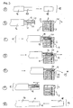
- FIG. 2 a lancet (2) is shown in a lancet magazine (1) according to FIG. 1 can be accommodated. While the lancet (2) in FIG. 1 is shown schematically in a side view, can be found in FIG. 2 a schematic plan view of a lancet (2).
- the lancet (2) consists essentially of a metal needle (11) with a tip, which is covered by a protective sheath (14). This protective sheath (14) must be removed from the lancet (2) before use of the lancet (2) to obtain blood.
- the lancet (2) further includes on the side opposite the protective sheath (14), a lancet body (12) which contains a pin (13) on both sides.
- the lancet body (12) and the protective cover (14) are made of an injection-moldable plastic.
- FIG. 3 shows schematically with reference to 7 sub-figures (A to G), as with the aid of a lancing device (15) a lancet (2), which is located at the removal point (4) of a lancet magazine (1), is removed from the lancet magazine (1).
- the lancing device (15) has essentially the shape of a fountain pen. It contains as essential components a handle body (16), a tip (17) and a protective cap (18). In the handle body (16) required for the lancing movement, movable mechanical components of the lancing device (15) are housed. These largely correspond to the state of the art, for example EP-A-0 565 970 , and will not be explained here.
- the lancet holder (19) is accommodated in the tip (17), which is exposed after removal or unscrewing of the protective cap (18) from the lancing device (15).
- Essential to the lancet holder (19) of the present, particularly preferred embodiment of a lancing device (15) are the flexible holding tongue (20) with a barb and the ejector (21), since these components of the lancet holder (19) directly with the lancet (2) in Lancet magazine (1) interact.
- the tip (17) of the lancing device is exposed ( Figure 3 A ).
- the lancing device (15) is moved forward with its tip (17) onto the lancet magazine (1), in which a lancet (2) is located at the removal point (4) ( FIG. 3B ).
- the tip (17) of the lancing device (15) has a recess, which makes it possible that the tip (17) can be pushed over the lancet magazine (1).
- the lancet holder (19) penetrates through the opening (9) in the lancet magazine.
- the flexible holding tongue (20) slides over the lancet (2) located at the removal point (4), whereby the holding tongue (20) is slightly bent upwards ( FIG. 3C ).
- the lancet Upon further insertion of the lancet holder (19) into the lancet magazine (1), the lancet is pushed by the ejector (20 a) in the direction of the opening (10) until the pin (13) of the lancet body (12) abuts against the stop (8) and thus further displacement of the lancet (2) is no longer possible ( FIG. 3 D ).
- the lancet holder (19) in the lancet magazine (1) pushes the ejector (20 a) no longer the entire lancet (2) but only the protective cover (14) in the direction of the opening (10).
- the protective cover (14) by the ejector (20 a) separated from the lancet tip and falls out of the opening (10).
- the flexible retaining tongue (20) engages with its barb in front of the lancet body (12) and thus holds the lancet (2) in the lancet holder (19) (FIG. Figure 3 E ).
- the lancet (2) which is located in the lancet holder (19), also removed from the magazine (1).
- the removal point (4) so space for a nachanzückende lancet (2) has become, which can be pushed manually by means of the transport device (5) to the removal point (4) ( FIG.
- the lancing device (15) with the protective cap (18) must be closed.
- the lancing device (15) can be automatically tensioned by turning the protective cap (18). It is thus available for blood collection.
- FIG. 4 A is a further, particularly preferred embodiment of the lancet magazine (1) according to the invention shown in a side view, in which the lancet magazine (1) partially is cut.
- the lancet magazine (1) has essentially the shape of an elongated flat cuboid. Similar to the embodiment of the FIG. 1 Here too, the lancets (2) are essentially linear next to one another, arranged in pairs, touching each other.
- the lancets (2) are automatically transported in the direction of the removal point (4) by means of a transport device (5) consisting essentially of a plate (25) and two coil springs (26) driving this plate (25).
- a second transport device (5 ') is provided in the area of the removal point (4).
- This consists essentially of a movable housing part (27) which is held by a coil spring (26) in the illustrated rest position.
- a movable housing part (27) which is held by a coil spring (26) in the illustrated rest position.
- a gripper system (28) which engages the uppermost, that is, the removal point (4) nearest lancet (2) when operating the Transportvorrichung (5').
- FIG. 4B are detailed drawings of schematic views of the lancing device (15) in side and frontal view and that part of the lancet magazine (1) shown, in which the lancing device (15) for removing a lancet (2) can be inserted.
- the upper left lancing device (15) is like the lancing device (15) off Figure 3 A illustrated only with the part relevant to the invention. Again, the remaining functional components are state of the art.
- the lancing device (15) contains a handle body (16) and a tip (17), in which a lancet holder (19) is housed, which in turn has a flexible retaining tongue (20).
- FIG. 4B These components of the lancing device (15) are partially cut in a side view.
- Right next to the side view in FIG. 4 B is a front view of the lancing device (15) to see.
- the supervision illustrates the relative position of the aforementioned components to each other.
- the guide groove (30) can be seen, which is provided in the piercing aid tip (17).
- FIG. 4B Below this frontal view of the lancing device (15) in FIG. 4B is a frontal detail view of the opening (9) of the lancet magazine (1) to see. Right next to it is a partial attached side view of the lancet magazine (1). In the frontal view of the opening (9) of the lancet magazine (1) in particular the gripper system (28) and the guide pin (29) can be seen.
- the gripper system (28) consists of two movable, barbed tongues which, upon depression of the movable housing part (27) by a holding device (32) which protrudes laterally as a hemispherical elevation from the inner surface of the housing wall of the lancet magazine (1) enclose and hold the lancet (2) held in the preliminary removal position (31) so that upon relaxing the coil spring (26) and the sliding housing part (27) sliding back into the starting position, a lancet (2) moves into the final removal position (33). is taken.
- the flexible tongue (38) is pressed outwards, whereupon it moves back into its slightly inwardly inclined rest position.
- the guide pin (29) moves during insertion of the lancing device (15) in the opening (9) in the guide groove (30) in the tip (17) of the lancing device (15). This ensures on the one hand that the lancing device (15) is inserted in the correct orientation in the opening (9). On the other hand can be achieved by suitable geometry of the guide groove (30) that the lancing device (15) when inserted into the lancet magazine (1) via the opening (9) rotates about its longitudinal axis. In this way, the lancet (2), which is located in the removal position (33), rotated about its longitudinal axis. In this case, the protective cover (14) of the lancet (2), as in FIG. 4 C and D is shown, are turned off from the rest of the lancet (2) and thus release the metal needle (11) or its tip.
- particularly preferred embodiment of the lancet (2) consists essentially of a metal needle (11), which is largely completely surrounded in this case by a plastic body (12).
- the protective cover (14) is part of the Kunststoffkörpes (12), wherein at the junction between the protective cover (14) and the remaining plastic body (12) a predetermined breaking point is provided, which upon rotation of the protective cover (14) relative to the plastic body (12). a separation of the protective cover (14) allowed.
- On both sides of the protective cover (14) is located in each case a survey (24), which serve to detachably connect a plurality of lancets (2) to a lancet set.
- the lancets (2) - similar to staples - connected via adhesive dots on the surveys (24) together to form a set of lancets.
- the lancet body (12) in the illustrated particularly preferred embodiment of the lancet (2) includes a funnel-shaped notch (22) and a pair of opposing V-shaped notches (23).
- the V-shaped recesses (23) can be used together with alternative, not shown embodiments of the lancet holder (19) of a lancing device (15).
- the lancet magazine (1) of in FIG. 4 shown preferred embodiment can be opened by the user to insert each a new lancet set.
- the housing of the lancet magazine (1) can be opened by folding away the transport device (5 ').
- the lancets (2) are individually or releasably connected connected as lancet set in the magazine (1) pushed.
- the transport device (5) is stretched by squeezing the coil springs (26) again.
- the transport device (5 ') is folded back.
- the magazine (1) is thus ready to use.
- FIG. 6 A further particularly preferred embodiment of the lancet magazine (1) (A, B) according to the invention and a lancet set (35) (C, D) suitable for this purpose is shown.
- the lancet magazine (1) of this preferred embodiment is substantially in the form of a flat, round disc, to which an insertion tube (37) is attached, through which via the opening (9) a lancing device for removing lancets (2) in the lancet magazine ( 1) can be introduced.
- On one of the circular sides of the lancet magazine (1) is a transparent viewing window (34) is provided, which allows to control the current level of the lancet magazine (1) with lancets (2).
- the viewing window (34) may consist of a transparent plastic connected to the housing (3).
- the entire housing (3) is made of a transparent plastic.
- the viewing window (34) may be configured only as an open recess of the housing (3).
- a transport device (5) can be operated, which brings, for example via a coil spring lancets in the removal position (33).
- a guide pin (29) which can interact with a guide groove in the lancing device.
- FIG. 6 C and D are shown a plan view and a front view of a lancet set (35), the view is partially cut from the front.
- the lancet set (35) consists of a plurality of lancets (2) which are arranged in a star shape around a circular, central plastic disc (36). The tips of the metal needles (11) of the lancets (2) stuck in the central plastic disc (36).
- the lancets themselves essentially correspond to the lancets as they are in FIG. 4C are shown.
- V-shaped recesses (23) in the lancet body (12) are again provided, which allow interaction with the lancet holder of a lancing device.
- the lancet magazine (1) in the FIGS. 6A and B shown preferred embodiment can be opened by the user to insert a new lancet set (35).
- the housing of the lancet magazine (1) can be opened by removing the upper, ie provided with a viewing window housing half.
- the lancets (2) are inserted as a lancet set (35).
- the spiral spring of the transport device (5) is tensioned.
- the removed housing half is again attached to the magazine (1), for example by clipping.
- the magazine (1) is thus ready to use.
Description
- Die Erfindung betrifft ein System geeignet zur Gewinnung einer Körperflüssigkeit, insbesondere von Blut, aus einer Körperpartie einer zu untersuchenden Person, wobei das System eine Stechhilfe, zwei oder mehrere Lanzetten und ein Lanzettenmagazin zur Bevorratung von zwei oder mehreren Lanzetten enthält. Die Erfindung betrifft weiterhin ein Lanzettenmagazin, das zum Einsatz in dem erfindungsgemäßen System geeignet ist, sowie die Verwendung des erfindungsgemäßen systems in einem Verfahren zur Entnahme einer Lanzette aus einem Lanzettenmagazin.
- Die Untersuchung von Blutproben ermöglicht in der klinischen Diagnostik das frühzeitige und zuverlässige Erkennen von pathologischen Zuständen sowie die gezielte und fundierte Kontrolle von Körperzuständen. Die medizinische Blutdiagnostik setzt stets die Gewinnung einer Blutprobe des zu untersuchenden Individuums voraus. Während in Kliniken und bei niedergelassenen Ärzten oftmals durch eine Venenpunktion mehrere Milliliter Blut einer zu untersuchenden Person für die Analyse gewonnen werden, um damit eine Vielzahl von Labortests durchführen zu lassen, reichen für einzelne Analysen, die gezielt auf einen Parameter gerichtet sind, heutzutage oftmals wenige Mikroliter Blut aus. Solch geringe Blutmengen erfordern keine Venenpunktion. Vielmehr genügt es hier, zur Blutgewinnung durch die Haut z. B. in die Fingerbeere oder das Ohrläppchen der zu untersuchenden Person mit Hilfe einer steilen, scharfen Lanzette zu stoßen, um so einige wenige Mikroliter Blut für die Analyse zu gewinnen. Insbesondere eignet sich diese Methode, wenn die Analyse der Blutprobe unmittelbar nach der Blutgewinnung durchgeführt werden kann.
- Vor allem im Bereich des sogenannten "Home-Monitoring", also dort, wo medizinische Laien selbst einfache Analysen des Bluts durchführen, und dort insbesondere für die regelmäßige, mehrmals täglich durchzuführende Blutgewinnung durch Diabetiker für die Kontrolle der Blutglucosekonzentration, werden Lanzetten und dazu passende Geräte (sogenannte Blutentnahmegeräte, Blutlanzettenvorrichtungen oder - wie sie im Folgenden genannt werden sollen - Stechhilfen), angeboten, die eine möglichst schmerzarme und reproduzierbare Blutgewinnung ermöglichen. Zudem soll die Verwendung von Lanzetten mit Stechhilfen die psychologische Schwelle beim Stechen des eigenen Körpers senken, was vor allem für Kinder, die an Diabetes erkrankt sind und auf regelmäßige Blutglucosetests angewiesen sind, von besonderer Bedeutung ist. Als Beispiele für Lanzetten und Stechhilfen seien die kommerziell erhältlichen Geräte und Lanzetten Glucolet® der Bayer AG und Softclix® der Boehringer Mannheim GmbH genannt. Solche Lanzetten und Geräte sind z. B. Gegenstand von
EP-A 0 565 970 ,US 4,442,836 oderUS 5,554,166 . - Bei den derzeit verfügbaren Systemen erfolgt die Bereitstellung der Lanzetten für die Verwendung in Stechhilfen meist in loser Form. Der Benutzer entnimmt manuell vor jedem Stechvorgang eine Lanzette aus einer Verpackung, beispielsweise einer Pappschachtel oder einer Röhre, in der eine Vielzahl von Lanzetten ungeordnet, lose geschüttet enthalten sind. Anschließend wird die Stechhilfe, beispielsweise durch Abschrauben oder Abziehen einer Schutzkappe, für die Aufnahme der Lanzette vorbereitet, wobei der Lanzettenhalter der Stechhilfe freigelegt wird. Der Lanzettenhalter dient einerseits der Aufnahme der Lanzetten. Andererseits wird durch ihn die Lanzette beim eigentlichen Stechvorgang geführt. Die aus der Packung entnommene Lanzette wird manuell in den Lanzettenhalter der Stechhilfe eingeführt und dort fixiert. Dann muß die Schutzhülle, welche die Lanzettenspitze umgibt und sowohl diese als auch den Benutzer schützt, von der Lanzette manuell abgenommen werden. Anschließend wird die Stechhilfe mit ihrer Schutzkappe wieder verschlossen. Die Schutzkappe sorgt dafür, daß die Lanzette von außen nicht mehr zugänglich ist. Sie besitzt meist eine Öffnung, durch welche die Lanzettenspitze beim eigentlichen Stechvorgang austreten kann. Schließlich wird die Stechhilfe gespannt und steht für den Stechvorgang zur Gewinnung von Blut zur Verfügung.
- Die Vielzahl der manuellen Bedienschritte wird vom Benutzer als nachteilig empfunden und ist vor allem bei eingeschränkter Wahrnehmung im Zustand einer Hypoglykämie problematisch. Zudem wird der Benutzer dazu verleitet, eine einmal eingelegt Lanzette mehrfach zum Stechen und Blutgewinnen zu verwenden. Dies ist zum einen aus hygienische Gründen bedenklich. Zum anderen führt die mehrmalige Benutzung der Lanzetten zu steigendem Schmerz für den Benutzer, denn da die Lanzetten als Einmalartikel konzipiert sind, werden sie schnell stumpf Zudem besteht mit den Stechhilfen und Lanzetten des Standes der Technik die Gefahr, daß
- Stechhilfen mit nicht passenden Lanzetten benutzt werden oder daß die Lanzetten unsachgemäß in die Stechhilfen eingelegt werden. Weiterhin kann sich ein Benutzer bei unsachgemäße Benutzung von Lanzetten und Stechhilfen unbeabsichtigt verletzen.
- Es mangelt deshalb nicht an Versuchen, die angesprochenen Nachteile zu beseitigen. Aus den US-Patentschriften
US 3,030,959 ,US 4,794,926 ,US 5,035,704 undUS 5,152,775 sind Stechhilfen bekannt, die mehrere Lanzetten in sich bevorraten und diese nacheinander einzeln für Stechvorgänge benutzen können. AusDE2803345 B1 ,US 5,514,152 undWO 98/14125 - Aufgabe der Erfindung ist es, die Nachteile des Standes der Technik zu beseitigen. Insbesondere ist es die Aufgabe der vorliegenden Erfindung, die Anzahl der manuellen Bedienschritte beim Einlegen einer Lanzette in eine Stechhilfe zu reduzieren und somit den Bedienkomfort für den Benutzer zu erhöhen. Zudem ist es Aufgabe der Erfindung, ein verwechslungsfreies Einlegen der Lanzette in die Stechhilfe zu gewährleisten und die Sicherheit für den Benutzer im Umgang mit Stechhilfe und Lanzette, insbesondere bei hypoglykämische Zuständen, zu erhöhen.
- Die Aufgabe wird durch den Gegenstand der Erfindung, wie er in den Patentansprüchen charakterisiert ist, gelöst.
- Gegenstand der Erfindung ist ein System geeignet zur Gewinnung einer Körperflüssigkeit, insbesondere von Blut aus einer Körperpartie einer zu untersuchenden Person enthaltend eine Stechhilfe, die zur Aufnahme einer Lanzette geeignet ist, ein Lanzettenmagazin zur Bevorratung von zwei oder mehreren Lanzetten, das eine Transportvorrichtung für die Lanzetten aufweist und eine Öffnung besitzt, in welche die Stechhilfe zur Entnahme einer Lanzette aus dem Lanzettenmagazin eingeführt werden kann, und zwei oder mehrere Lanzetten.
- Das erfindungsgemäße System ist zur Gewinnung einer Körperflüssigkeit, insbesondere von Blut, einer zu untersuchenden Person geeignet. Dabei durchstößt die von der Stechhilfe gehaltene, geführte und angetriebene Lanzette kurzzeitig und mit definierter Einstichtiefe die Haut dieser Person, wodurch eine winzige Wunde entsteht. Auf der Oberfläche der Wunde sammelt sich ein Tropfen der Körperflüssigkeit, insbesondere Blut von in aller Regel wenigen Mikroliter bis maximal 100 Mikroliter Volumen. Vorzugsweise wird die Körperflüssigkeit direkt im Anschluß an die Gewinnung für eine diagnostische Untersuchung eingesetzt. Die Probe der Körperflüssigkeit kann jedoch auch für eine spätere Untersuchung aufbewahrt werden.
- Insbesondere kann mit dem erfindungsgemäßen System Kapillarblut aus einer Körperpartie, wie z. B. einer Fingerbeere oder einem Ohrläppchen, gewonnen werden. Das System kann sowohl von der zu untersuchenden Person selbst, beispielsweise einem Diabetiker, der seinen Blutglucosegehalt bestimmen möchte, als auch von einem Dritten, z. B. einem Arzt oder einer Krankenschwester zur Gewinnung von Blutproben eines Patienten, angewendet werden.
- Das erfindungsgemäße System enthält eine Stechhilfe, Lanzetten und ein Lanzettenmagazin, die in ihrer Form und Funktion so aufeinander abgestimmt sind, daß ein optimales Zusammenwirken der einzelnen Systemkomponenten miteinander erreicht wird. Die einzelnen Komponenten und deren Zusammenwirken sollen im Folgenden näher erläutert werden.
- Zentrale Komponente des erfindungsgemäßen Systems ist das Lanzettenmagazin. Es dient der Aufnahme, Aufbewahrung und dem Zurverfügungstellen der Lanzetten und stellt die funktionale Verbindung zwischen Lanzetten und Stechhilfe her. Zur Erfüllung dieser Zwecke besitzt das Lanzettenmagazin
- ein Gehäuse, in dem die Lanzetten aufbewahrt werden,
- eine Entnahmestelle für eine Lanzette und gegebenenfalls Mittel, die eine Lanzette in der Entnahmestelle halten,
- eine Vorrichtung, mit der die Lanzetten manuell oder automatisch in die Entnahmestelle transportiert werden können,
- eine Öffnung, in welche die Stechhilfe mit ihrer Spitze zur Entnahme einer Lanzette eingeführt werden kann und die gegebenenfalls Mittel zur Führung der Stechhilfe enthält,
- gegebenenfalls eine weitere, vorzugsweise der Öffnung für die Stechhilfe gegenüberliegende Öffnung, durch welche die Schutzhülle der Lanzettennadeln nach deren Entnahme mit Hilfe der Stechhilfe aus dem Inneren des Lanzettenmagazins entfernt werden kann, und
- gegebenenfalls eine verschließbare Öffnung, durch die Lanzetten in das Magazin gefüllt werden können.
- Vorzugsweise dient das Lanzettenmagazin nicht vordringlich der Sterilität der Lanzetten. Diese wird vorzugsweise durch geeignete konstruktive Maßnahmen an der Lanzette selbst verwirklicht, beispielsweise durch Einsiegeln der Lanzettenspitze in eine abnehmbare, dichte Kunststoffschutzhülle.
- Das Gehäuse des Lanzettenmagazins ist aus einem Metall, beispielsweise Aluminium, oder einem Kunststoff, z. B. Polypropylen oder Polyethylen, gefertigt. Vorzugsweise ist das Gehäuse mittels Spritzguß aus einem spritzgußfähigen Material, insbesondere Kunststoff, gefertigt. Das Gehäuse kann prinzipiell jede für die Funktion des Lanzettenmagazins geeignete Form haben. Als bevorzugt hat es sich herausgestellt, daß das Lanzettenmagazin entweder die Form eines länglichen, flachen Quaders, also ähnlich einer Zigarettenschachtel, oder die Form einer flachen quadratischen, vieleckigen oder runden Scheibe, z. B. ähnlich einer Puderdose, aufweist. Selbstverständlich können Kanten und Ecken des Gehäuses aus Design- oder Ergonomiegründen abgerundet sein. Die Dimensionen des Lanzettenmagazins werden im wesentlichen durch die Größe der Lanzetten und die Anzahl der zu bevorratenden Lanzetten bestimmt. Erfindungsgemäß können zumindest zwei Lanzetten im Magazin aufbewahrt werden. Vorzugsweise dient das Lanzettenmagazin der Bevorratung von 10 bis 200 Lanzetten. Besonders bevorzugt enthält es 20 bis 50 Lanzetten.
- In einer bevorzugten Ausführungsform hat das Lanzettenmagazins die Form eines flachen, länglichen Quaders. Die kurzen, schmalen Flächen entsprechen in Länge und Breite den entsprechenden Dimensionen einer einzelnen Lanzette; die langen, schmalen Flächen entsprechen in ihrer Breite der Breite einer Lanzette und in ihrer Länge mindestens der Summe der Höhen der Lanzetten, die im Magazin untergebracht werden sollen. Die Dimensionen der großen Quaderflächen ergeben sich entsprechend. Die Lanzetten sind in dieser bevorzugten Ausführungsform im Magazin sich paarweise berührend neben- bzw. übereinander oder sich gegenüberliegend, z. B. Kopf an Kopf, gestapelt und können sowohl einzeln als auch lösbar miteinander zu einem Lanzettensatz verbunden vorliegen, beispielsweise durch Verkleben oder Verschweißen der einzelnen Lanzetten an ihren Berührungsstellen, ähnlich also wie Heftklammern miteinander zu einem Satz verbunden sind, oder durch Verbindung über dünne Kunststoffstege.
- In einer alternativen, ebenfalls bevorzugten Ausführungsform hat das Lanzettenmagazin die Form einer flachen quadratischen, regelmäßig oder unregelmäßig vieleckigen oder runden Scheibe. Die Lanzetten sind in dieser Ausführungsform vorzugsweise sternförmig in einer Ebene um eine zentrale Achse angeordnet, wobei besonders bevorzugt die Lanzettenspitzen in einer gemeinsamen, zentralen Kunststoffscheibe stecken und die Lanzetten so miteinander zu einer Lanzettenscheibe verbunden sind. Auf diese Weise werden zudem die Lanzettenspitzen steril gehalten.
- Unabhängig von der äußeren Form des Lanzettenmagazins - ob quaderförmig oder scheibenförmig - besitzt das erfindungsgemäße Lanzettenmagazin eine Entnahmestelle oder -position für eine Lanzette. In diese Position wird mit Hilfe einer im Magazin enthaltenen Transportvorrichtung eine Lanzette zur Entnahme durch die Stechhilfe befördert. Die Transportvorrichtung dient dazu, nach der Entnahme einer Lanzette aus dem Magazin die nächste, d. h. die der entnommenen Lanzette ursprünglich benachbarte, im Magazin enthaltene Lanzette an die Entnahmestelle des Magazins zu befördern. Dabei kann die Transportvorrichtung dieses Befördern der nächsten Lanzette zur Entnahmestelle automatisch bewerkstelligen, so daß jederzeit solange Lanzetten im Magazin enthalten sind eine Lanzette in der Entnahmeposition ist, oder aber das Befördern der nächsten Lanzette geschieht nicht automatisch, durch die Entnahme einer Lanzette ausgelöst, sondern manuell durch den Benutzer. Der Transportmechanismus kann mit einem Zählwerk gekoppelt sein, der dem Anwender anzeigt, wieviele Lanzetten aus dem Magazin bereits verbraucht bzw. wieviele Lanzetten im Magazin noch vorrätig sind.
- Die Transportvorrichtung kann in einer bevorzugten Ausführungsform sämtliche im Magazin verbleibenden Lanzetten nachrücken. In einer anderen Ausführungsform ist es jedoch möglich, immer nur eine, vorzugsweise die nächstgelegene, Lanzette zur Entnahmestelle weiterzutransportieren.
- In einer bevorzugten Ausführungsform werden die Lanzetten manuell mit Hilfe eines von außen zu bedienenden Schiebers in die Entnahmeposition gebracht. Der Schieber kann dabei kontinuierlich oder in diskreten Schritten, beispielsweise gerastert, mit Hilfe beispielsweise eines Bedienungsknopfes in Richtung der Entnahmeposition bewegt werden und so die im
- Magazin enthaltenen Lanzetten transportieren. Die Lanzetten liegen dabei vorzugsweise mit einer Seitenfläche ganz oder teilweise auf dem im Magazin befindlichen Teil des Schiebers auf.
- In einer weiteren bevorzugten Ausführungsform werden die Lanzetten mit Hilfe eines automatischen Vorschubsystems, beispielsweise im Falle des quaderförmigen Magazins über eine von Schraubenfedern getriebene, linear verschiebbare Platte oder im Falle des scheibenförmigen Magazins über eine Spiralfeder, die so auf die Lanzetten einwirkt, daß sie eine geführte, ebene Kreisbewegung ausführen, in die Entnahmeposition bewegt. Das automatische Vorschubsystem kann auch von einem Motor getrieben sein.
- Das Auslösen der Transportbewegung der Lanzetten im Magazin kann im Falle des automatischen Vorschubsystems manuell, beispielsweise durch Betätigen eines Schalters, erfolgen.
- Es ist jedoch auch möglich, daß die Transportbewegung automatisch durch die Entnahme einer Lanzette aus dem Magazin in Gang gesetzt wird.
- Sowohl in den inneren Magazinwänden als auch bei den Lanzetten können Anschläge sowie Führungsnuten und -zapfen oder -stege vorhanden sein, die für eine präzise Positionierung der Lanzetten, insbesondere während des Transports der Lanzetten in die Entnahmeposition des Magazins, sorgen.
- In einer weiteren, besonders bevorzugten Ausführungsform des erfindungsgemäßen Lanzettenmagazins werden die Lanzetten mit Hilfe einer ersten Transportvorrichtung in eine vorläufige Entnahmeposition gebracht, von der aus sie mittels eines zweiten Transportmechanismus in die endgültige Entnahmeposition bewegt werden. Die erste Transportvorrichtung kann dabei sowohl ein manuell zu bedienender Schieber als auch ein automatisches Vorschubsystem sein. Die zweite Transportvorrichtung ist in dieser besonders bevorzugten Ausführungsform ein beweglicher Teil des Lanzettenmagazins, beispielsweise ein linear bewegliches, auf einer oder mehreren Federn gelagertes Teil des Gehäuses. Durch Druck auf dieses Gehäuseteil wird dieses auf eine in der vorläufigen Entnahmeposition befindliche Lanzette zubewegt und greift diese Lanzette mit einem Greifsystem, beispielsweise über ein Widerhakensystem, welches gegebenenfalls an flexiblen Zungen angebracht ist, oder über Magnete. Beim Zurückgleiten des beweglichen Teils des Magazins wird die Lanzette in die endgültige Entnahmeposition befördert und dort über das Greifsystem gehalten, bis die Lanzette mit Hilfe einer Stechhilfe aus dem Magazin entnommen wird.
- Im Bereich der Entnahmestelle findet sich eine vorzugsweise verschließbare Öffnung im Magazin, in welche die Stechhilfe zumindest mit ihrer Spitze eingeführt werden kann, um so aus dem Inneren des Lanzettenmagazins eine einzelne Lanzette zu entnehmen. Geometrie und Größe der Öffnung richten sich nach den entsprechenden Dimensionen der Stechhilfe. Vorzugsweise passen Stechhilfe und Öffnung wie Schlüssel und Schloß zueinander, so daß eine eindeutige und präzise Ausrichtung dieser beiden Systemkomponenten während des Entnahmevorgangs gewährleistet ist. Um das Einführen der Stechhilfe in die Öffnung zu erleichtern, kann die Öffnung konisch oder trichterförmig gestaltet sein, so daß sie nach außen hin größer als für die Aufnahme der Stechhilfenspitze erforderlich ist. Es ist ebenfalls möglich, daß sich die Stechhilfe im Bereich ihrer Spitze, die in das Lanzettenmagazin eingeführt wird, verjüngt, um somit das Einführen zu erleichtern.
- In einer bevorzugten Ausführungsform ist im Inneren der Öffnung des Magazins ein Führungszapfen vorgesehen, der in eine entsprechende Führungsnut in der Spitze der Stechhilfe eingreift. Selbstverständlich kann der Zapfen auch auf der Stechhilfe sitzen, wobei die Führungsnut dann in der Öffnung des Magazins liegt.
- Besonders bevorzugt dienen Führungszapfen und Führungsnut dazu, die Stechhilfe beim Einführen in das Magazin oder beim Entfernen aus dem Magazin - bei Bewegungen also, die im wesentlich als linear und parallel zur Längsachse der Stechhilfe zu betrachten sind - automatisch und unwillkürlich zumindest teilweise um ihre Längsachse zu drehen. Diese Drehbewegung dient dazu, mit der Stechhilfe oder einem Teil der Stechhilfe die Lanzette um ihre Längsachse zu drehen, wobei die Schutzhülle, die auf der Lanzettenspitze sitzt und die in diesem Fall nicht-drehbar im Magazin gelagert ist, abgedreht wird. Aus dem Magazin wird somit die Lanzette ohne Schutzhülle entnommen; diese verbleibt zunächst im Magazin und kann gegebenenfalls über eine weitere, vorzugsweise der Öffnung zum Einführen der Stechhilfe gegenüberliegende, Öffnung aus dem Magazin entfernt, z. B. ausgeworfen, werden.
- Das Lanzettenmagazin kann als Einwegmagazin (Wegwerfmagazin) konzipiert sein oder es kann über Mittel verfügen, die ein Befüllen des Magazins mit Lanzetten erlauben. Beispielsweise kann ein Teil des Gehäuses des Lanzettenmagazins über ein Scharnier beweglich sein, und somit quasi als Tür oder Klappe dienen, durch die das Magazin mit Lanzetten bestückt werden kann. Ebenfalls möglich ist es, daß ein Teil des Magazins als Schublade ausgestaltet ist, in die Lanzetten eingelegt und in das Magazin geschoben werden können.
- Das Lanzettenmagazin verfügt in einer bevorzugten Ausführungsform über Mittel, die es erlauben, den aktuellen Inhalt an Lanzetten von außen zu erkennen. Beispielsweise kann das Gehäuse des Lanzettenmagazin ganz oder teilweise transparent sein. Möglich ist jedoch auch, den Füllstand über die relative Lage eines gegebenenfalls vorhandenen Schiebers zu ermitteln, beispielsweise durch Rasterung der Schieberposition mit gleichzeitigem Vorhandensein einer Füllstandsskala.
- Lanzetten, die für das erfindungsgemäße System geeignet sind, sind prinzipiell im Stand der Technik, beispielsweise in
EP-A 0 565 970 , beschrieben. Für bevorzugte Ausführungsformen des erfindungsgemäße Systems geeignet sind auch im Handel erhältliche Lanzetten, beispielsweise Softclix® II Lancet von Boehringer Mannheim GmbH. - Erfindungsgemäß bevorzugte Lanzetten besitzen eine Nadel aus Metall, Keramik oder Kunststoff, deren eines Ende (die Spitze) spitz ausgeformt ist, beispielsweise durch einen Schleifprozeß. Der hintere, von dieser Spitze abgewandte Teil der Lanzettennadel ist in einer bevorzugten Ausführungsform üblicherweise von einem Lanzettenkörper aus Kunststoff ganz oder teilweise umschlossen. Die Herstellung erfolgt üblicherweise derart, daß die Lanzettennadel in einer Kunststoffspritzform positioniert und der Lanzettenkörper angespritzt wird. Dabei kann gleichzeitig auch eine Schutzhülle aus Kunststoffüber die Spitze der Lanzette gespritzt werden. Die Schutzhülle kann dabei vom Lanzettenkörper losgelöst vorliegen. Es ist jedoch auch möglich, daß Schutzhülle und Lanzettenkörper eine Einheit bilden, wobei in diesem Fall zwischen Schutzhülle und Lanzettenkörper eine Sollbruchstelle vorgesehen ist, so daß die Schutzhülle sauber von der Lanzette abgenommen werden kann.
- Erfindungsgemäß geeignet sind jedoch auch Lanzetten, die keinen umhüllenden Körper für die Lanzettennadel aufweisen. Zur Vereinfachung soll im Folgenden der Begriff "Lanzette" für alle Varianten, d. h. Lanzettennadeln mit und ohne Lanzettenkörper, verwendet werden.
- Die bevorzugte Lanzette für das erfindungsgemäße System enthält eine Metallnadel mit einer scharfen Spitze, die beim Vorgang des Stechens der zu untersuchenden Person zur Blutgewinnung durch deren Haut gestochen wird. Die Metallnadel wird vorzugsweise von einem Lanzettenkörper, d. h. einem Kunststoff- oder Metallkörper, gehalten, der die Handhabung der Nadel erleichtert.
- Die für das erfindungsgemäße System geeigneten Lanzetten enthalten vorzugsweise eine teilweise mit einem Kunststoffkörper umhüllte Metallnadel, wobei der Kunststoffkörper vorzugsweise Mittel enthält, die ein Greifen und Halten der Lanzette durch eine Stechhilfe ermöglichen. Zum Beispiel kann der Kunststoffkörper ein Paar von gegenüberliegenden, V-förmigen
- Aussparungen, umlaufende Einkerbungen oder trichterförmige Vertiefungen besitzen, in die komplementär gestaltete Widerhaken oder elastische Zungen des Lanzettenhalters der Stechhilfe eingreifen und die Lanzette somit festhalten können. Selbstverständlich sind jedoch auch Erhebungen auf dem Lanzettenkörper möglich, die in entsprechende Aussparungen im Lanzettenhalter der Stechhilfe eingreifen können.
- Weiterhin sind in einer bevorzugten Ausführungsform am Kunststoffkörper Mittel vorhanden, die verhindern, daß die Lanzette beim Greifvorgang durch die Stechhilfe im Magazin verschoben oder gar aus dem Lanzettenmagazin geschoben werden kann. Beispielsweise können am Lanzettenkörper Zapfen oder Stege vorgesehen sein, die in entsprechende Führungsnuten im Lanzettenmagazin eingreifen und so in ihrer Relativposition zur eingeführten Stechhilfe beim Greifvorgang gehalten werden. Selbstverständlich ist es auch möglich, daß der Lanzettenkörper die Nut(en) und das Magazin einen oder mehrere entsprechende, in die Nut(en) eingreifende Stege besitzt.
- Die Lanzettenspitze ist im Magazin vorzugsweise durch eine Schutzhülle, beispielsweise eine Kunststoffumhüllung, geschützt. Die Schutzhülle dient einerseits dazu, die Lanzettenspitze vor äußeren schädlichen Einwirkungen, wie z. B. Verbiegen oder Verschmutzen, was einen Verlust der Sterilität der Lanzettenspitze bedeuten würde, zu schützen, und andererseits den Benutzer, beispielsweise beim Befüllen des Magazins mit Lanzetten, vor ungewolltem Stechen durch die Lanzette zu bewahren. Die Schutzhülle kann mit dem Kunststoffkörper der Lanzette verbunden sein oder von diesem getrennt sein, wobei die verbundene Variante bevorzugt ist. Die Schutzhülle kann ein Vollkunststoff sein, der die Lanzettenspitze vollständig berührend umschließt, oder in Form eines Hohlkörpers um die Lanzettenspitze geformt sein. Jede Lanzette kann eine individuelle Schutzhülle besitzen, wie es bei den Lanzetten aus dem Stand der Technik bisher üblich ist. Es ist jedoch auch möglich, daß in einer bevorzugten Ausführungsform mehrere Lanzettenspitzen bzw. sämtliche im Lanzettenmagazin vorhandenen Lanzetten mit ihren Spitzen in einem gemeinsamen Kunststoffkörper, insbesondere einer gemeinsamen, zentralen Kunststoffscheibe, stecken, der als Schutzhülle für die Lanzettenspitzen dient.
- Für die besonders bevorzugte erfindungsgemäße Variante des Lanzettenmagazins, bei der die Lanzetten in das Magazin nachgefüllt werden können, hat es sich als vorteilhaft herausgestellt, daß die einzelnen Lanzetten untereinander zu einem Lanzettensatz verbunden vorliegen. Besonders bevorzugt enthält ein solcher Lanzettensatz zwei oder mehrere Lanzetten, welche - beispielsweise im Bereich der Spitzen oder der Lanzettenkörper - lösbar miteinander verbunden sind. Dies kann einerseits auf die oben beschriebene Art geschehen, d. h. dadurch, daß mehrere Lanzettenspitzen bzw. sämtliche im Lanzettenmagazin vorhandenen Lanzetten mit ihren Spitzen in einem gemeinsamen, vorzugsweise zentral angeordneten Kunststoffkörper stecken, andererseits aber auch dadurch erreicht werden, daß die Kunststoffkörper oder - schutzhüllen individueller Lanzetten miteinander lösbar verbunden, z. B. verklebt sind. Die Verbindung kann dabei mit Hilfe von Klebebändern, wie es z. B. bei Elektronikbauteilen üblich ist, oder direkt, wie es beispielsweise für Heftklammern bekannt ist, erfolgen. Zudem ist es möglich, die Lanzettenkörper durch Kunststoffstege miteinander zu verbinden oder die Lanzetten über eine gemeinsame Halterung, beispielsweise in Form einer Schiene oder einer Gliederkette, lösbar aneinander zu koppeln.
- Stechhilfen sind in einer Vielzahl von Formen aus dem Stand der Technik, beispielsweise aus
EP-A 0 565 970 , bekannt und im Handel erhältlich, z. B. unter dem Namen Softclix® II von Boehringer Mannheim GmbH. Unter Bezug auf den Stand der Technik, insbesondere aufEP-A 0 565 970 , erübrigt es sich hier deshalb, auf die allgemeinen Merkmale und Funktionsweisen solcher Stechhilfen - oder Blutlanzettenvorrichtungen, wie sie auch genannt werden - - Erfindungsgemäße stechhilfen, sind längliche, zylindrische Stechhilfen, d. h. solche, die im wesentlichen die Form eines Füllfederhalters besitzen. Diese Stechhilfen besitzen im Inneren einen Mechanismus, der die Lanzette beim Stechvorgang geführt auf die gewünschte Einstichstelle in der Haut der zu untersuchenden Person zu- und nach dem Stechen wieder wegbewegt. Meist wird dieser Mechanismus durch eine gespannte Feder angetrieben, die manuell gespannt werden muß, weshalb für diese Ausführungsform geeignete Spannvorrichtungen vorhanden sein müssen. Zum Auslösen des Mechanismus kann auf der Außenseite der Stechhilfe ein Auslöseknopf vorhanden sein.
- Stechhilfen in Form eines Füllfederhalters besitzen einen Griftkörper, welcher der bequemen Handhabung der Stechhilfe dient und in dessen Inneren meist ein Großteil des oben beschriebenen Mechanismus beherbergt wird. Zudem sind im Bereich des Griffkörpers oftmals die Bedienungsknöpfe zum Auslösen des Stoßmechanismus und gegebenenfalls zum Auswerfen gebrauchter Lanzetten aus der Stechhilfe vorhanden.
- An einem Ende der Stechhilfe, welches als Spitze der Stechhilfe bezeichnet werden soll, befindet sich der Lanzettenhalter. Dieser kann unter einer abnehmbaren Schutzkappe verborgen sein. Für die Erfindung wesentlich ist, daß der Lanzettenhalter der Stechhilfe Mittel enthält, die ein Greifen einer Lanzette ermöglichen, und die somit geeignet sind, eine Lanzette aus einem Lanzettenmagazin zu entnehmen. Der Lanzettenhalter kann zu diesem Zweck in das Lanzettenmagazin über dessen Öffnung eingeführt werden, um eine Lanzette zu entnehmen. Der Lanzettenhalter stellt quasi diejenige Spitze der Stechhilfe dar, die zur Lanzettenentnahme in das Lanzettenmagazin eingeführt wird. Seine genaue Form ergibt sich einerseits aus der Form der Lanzetten, die in ihm aufgenommen und von ihm gegriffen werden sollen, und andererseits aus der Öffnung des Lanzettenmagazins, in die er eingeführt werden soll. Vorzugsweise entspricht der Lanzettenhalter der Stechhilfe demjenigen, der aus
EP-A 0 565 970 bekannt ist. - Für das erfindungsgemäße System bestehend aus Stechhilfe, Lanzettenmagazin und Lanzetten hat es sich als vorteilhaft herausgestellt, daß die Stechhilfe in dem Teil, welcher in das Lanzettenmagazin zur Entnahme einer Lanzette eingeführt wird, eine Führungsnut oder einen Führungszapfen aufweist, der mit einer entsprechenden Vorrichtung in der Öffnung des Lanzettenmagazins wechselwirken kann. Dadurch kann ein verwechslungsfreies Zusammenführen von Stechhilfe und Magazin gewährleistet werden. Zudem kann durch entsprechende Formung der Nut - sei es in der Stechhilfe oder in der Öffnung des Magazins - wie weiter oben ausgeführt eine Drehung der Stechhilfe um deren Längsachse erzwungen werden, so daß sich diese beim Einführen in das Magazin oder bei dessen Herausnehmen aus dem Magazin dreht. Dabei wird ebenfalls die Lanzette im Lanzettenhalter um ihre Längsachse gedreht und somit die Schutzhülle um die Lanzettenspitze abgedreht. Auf diese Weise wird gewährleistet, daß sich die Lanzette ohne Schutzhülle in der Stechhilfe befindet. Ein manuelles Abdrehen der Schutzhülle entfällt dadurch und die Verletzungsgefahr für den Benutzer wird minimiert. Zudem wird die Anzahl der Bewegungsabläufe, die zum Einlegen einer Lanzette in die Stechhilfe erforderlich sind, minimiert und der gesamte Vorgang des Einlegens damit für den Benutzer erleichtert.
- Ein weiterer Gegenstand der Erfindung ist ein Lanzettenmagazin zur Bevorratung von zwei oder mehreren Lanzetten, welches zur Verwendung in dem erfindungsgemäßen System geeignet ist. Ein solches Lanzettenmagazin ist bereits weiter oben im Zusammenhang mit dem erfindungsgemäßen System beschrieben worden.
- Schließlich ist ein weiterer Gegenstand der Erfindung die verwendung des erfindungs gemäßen systems in einem Verfahren zur Entnahme einer Lanzette aus einem Lanzettenmagazin, wobei eine Lanzette, die sich im Lanzettenmagazin befindet, manuell oder automatisch mit Hilfe einer im lauzettenengram vorhandenen Transportvorrichtung in eine Entnahmeposition im Inneren des Lanzettenmagazins transportiert wird und eine Stechhilfe teilweise in eine dafür vorgesehene Öffnung des Lanzettenmagazins eingeführt wird. Beim teilweisen Einführen der Stechhilfe greift diese automatisch die Lanzette, die sich in der Entnahmeposition befindet. Die Stechhilfe wird schließlich mit der gegriffenen Lanzette aus dem Lanzettenmagazin herausgenommen.
- Vorzugsweise wird entweder beim Einführen der Stechhilfe in das Lanzettenmagazin, d. h. beim Greifen der Lanzette durch die Stechhilfe, oder beim Entnehmen der Stechhilfe aus dem Lanzettenmagazin die Stechhilfe und somit auch die Lanzette verdreht, so daß die Schutzhülle aus Kunststoff, welche die Nadelspitze der Lanzette schützt, abgedreht wird. Besonders bevorzugt wird dieses Verdrehen durch entsprechende Mittel sowohl in der Stechhilfe als auch im Lanzettenmagazin, beispielsweise eine gekrümmte Führungsnut auf der einen und einen entsprechenden Führungszapfen auf der anderen Seite, automatisch bewirkt.
- Die Vorteile der Erfindung können wie folgt.zusammengefaßt werden:
- ◆ Durch das erfindungsgemäße System aus Lanzettenmagazin, Lanzetten und Stechhilfe wird der Lanzettenwechsel für den Benutzer vereinfacht, der Zeitaufwand dafür verringert und damit die Bereitschaft erhöht, einmal benutzte Lanzetten nicht wiederzuverwenden. Dies minimiert die Infektionsgefahr und trägt zur Reduktion des Schmerzes bei der Blutgewinnung bei. Zudem ist die Handhabung des Systems bei hypoglykämischen Zuständen erleichtert.
- ◆ Da die Lanzetten vom Benutzer nicht mehr separat in die Hand genommen werden müssen, können die Lanzetten deutlich kleiner als bisher übliche Lanzetten gestaltet werden, wodurch sich der Materialaufwand bei der Fertigung reduziert. Zudem fällt bei der Entsorgung der Lanzetten weniger Müll an. Schließlich kann das ganze System kompakter gehalten werden, so daß dessen Mitnahme für den Benutzer erleichtert wird.
- ◆ Die Lanzetten werden im Lanzettenmagazin in einer eindeutigen Ausrichtung für die Stechhilfe angeboten, so daß ein Einlegen in falscher Orientierung ausgeschlossen werden kann.
- ◆ Durch das Schlüssel-Schloß-Prinzip von Lanzettenmagazin und Stechhilfe ist ein Verwenden von nicht geeigneten Lanzetten für die Stechhilfe ausgeschlossen.
- ◆ Das Lanzettenmagazin kann als wiederverwendbarer Systembestandteil jeweils mit neuen Lanzetten befüllt werden, entweder durch den Hersteller, den Vertrieb oder den Verbraucher. Die Lanzetten selbst können deshalb platz- und müllsparend mit minimaler Verpackung in den Handel gebracht werden.
- Die Erfindung wird durch die nachfolgenden Zeichnungen näher erläutert.
-
Figur 1 zeigt schematisch eine Seitenansicht einer bevorzugten Ausführungsform eines erfindungsgemäßen Lanzettenmagazins, bei dem eine Seitenwand entfernt wurde, um so einen Einblick in das Magazin und auf die darin enthaltenen Lanzetten zu ermöglichen. -
Figur 2 zeigt schematisch eine Aufsicht auf eine bevorzugte Ausführungsform einer Lanzette, die in einem Lanzettenmagazin gemäßFigur 1 untergebracht werden kann. -
Figur 3 zeigt schematisch anhand von sieben Teilfiguren (A bis G), wie mit einer Stechhilfe Lanzetten aus einem Lanzettenmagazin gemäßFigur 1 entnommen werden können. -
Figur 4 zeigt schematisch eine Seitenansicht einer weiteren bevorzugten Ausführungsform eines erfindungsgemäßen Lanzettenmagazins, bei dem eine Seitenwand entfernt wurde, um so einen Einblick in das Magazin und auf die darin enthaltenen Lanzetten zu ermöglichen (Teilfigur A), schematische Seiten- und Frontansichten derjenigen Teile eines bevorzugten Lanzettenspenders und einer entsprechenden Stechhilfe (Teilfigur B), die zur Lanzettenentnahme miteinander wechselwirken, sowie eine Aufsicht (Teilfigur C) und eine Seitenansicht (Teilfigur D) einer bevorzugte Ausführungsform einer Lanzette, die in dem Lanzettenmagazin gemäßFigur 4 A untergebracht werden kann. -
Figur 5 zeigt schematisch anhand von zehn Teilfiguren (A bis K), wie mit einer Stechhilfe Lanzetten aus einem Lanzettenmagazin gemäßFigur 4 entnommen werden können. -
Figur 6 zeigt schematisch anhand von vier Teilfiguren (A bis D) eine weitere bevorzugte Ausführungsform eines Lanzettenmagazins in Aufsicht (A) und von vorne (B), sowie einen für dieses Lanzettenmagazin geeigneten Satz von lösbar miteinander verbundenen Lanzetten, ebenfalls in Aufsicht (C) und von vorne (D). Die Ansichten von vorne (B, D) sind dabei teilweise angeschnitten, um konstruktive Details zu verdeutlichen. -
Figur 7 zeigt schematisch anhand von sechs Teilfiguren (A bis F), wie mit einer Stechhilfe Lanzetten aus einem Lanzettenmagazin gemäßFigur 6 entnommen werden können. - Die Ziffern in den Figuren bedeuten:
- 1
- Lanzettenmagazin
- 2
- Lanzette
- 3
- Gehäuse
- 4
- Entnahmestelle
- 5,5'
- Transportvorrichtung
- 6
- Bedienungsknopf für Transportvorrichtung 5
- 7
- Führungsnut für Transportvorrichtung 5
- 8
- Anschlag
- 9
- Öffnung zum Einführen der Stechhilfe 15
- 10
- Öffnung zum Auswerfen der Schutzhülle 14
- 11
- Metallnadel
- 12
- Lanzettenkörper
- 13
- Zapfen
- 14
- Schutzhülle
- 5
- Stechhilfe
- 16
- Griffkörper
- 17
- Spitze
- 18
- Schutzkappe
- 19
- Lanzettenhalter
- 20
- flexible Haltezunge mit Widerhaken
- 21
- Auswerfer
- 22
- trichterförmige Kerbe im Lanzettenkörper 12
- 23
- V-förmige Aussparung im Lanzettenkörper 12
- 24
- Erhebung auf Schutzhülle 14
- 25
- Platte
- 26
- Schraubenfeder
- 27
- bewegliches Gehäuseteil
- 28
- Greifersystem
- 29
- Führungszapfen
- 30
- Führungsnut
- 31
- Lanzette 2 in vorläufiger Entnahmeposition
- 32
- Haltevorrichtung
- 33
- Lanzette 2 in endgültiger Entnahmeposition
- 34
- Sichtfenster
- 35
- Lanzettensatz
- 36
- Kunststoffscheibe
- 37
- Einführungsstutzen
- 38
- flexible Zunge
- In
Figur 1 ist schematisch die Seitenansicht einer besonders bevorzugten Ausführungsform eines Lanzettenmagazins (1) abgebildet, bei dem eine Seitenwand des Gehäuses (3) entfernt wurde, um so einen Einblick in das Lanzettenmagazin (1) und auf die darin enthaltenen Lanzetten (2) sowie weitere funktionale Bestandteile zu ermöglichen. Das Lanzettenmagazin (1) hat im wesentlichen die Form eines länglichen, flachen Quaders, in dem die Lanzetten (2) linear nebeneinander, sich jeweils paarweise berührend angeordnet sind. Die Lanzetten können mit Hilfe einer Transportvorrichtung (5) manuell zu Entnahmestelle (4) geschoben werden, wozu auf der Außenseite einer der langen, schmalen Seiten des Lanzettenmagazins (1) ein Bedienungsknopf (6) für die Transportvorrichtung (5) vorgesehen ist. Das Verschieben der Transportvorrichtung (5) mit Hilfe des Bedienungsknopfes (6) kann kontinuierlich oder diskontinuierlich, beispielsweise gerastert, geschehen. Die Position des Bedienungsknopfes (6) erlaubt es, den aktuellen Füllstand des Magazins (1) zu erkennen. - Innerhalb des Lanzettenmagazins (1) ist eine Führungsnut (7) enthalten, in der die Transportvorrichtung (5) und die Schutzhüllen (14) der Lanzetten (2) geführt werden. Die Schutzhüllen (14), die Transportvorrichtung (5) und die Führungsnut (7) sind in Größe und Form aneinander entsprechend angepaßt.
- Ebenfalls im Inneren des Gehäuses (3) des Lanzettenmagazins (1) befindet sich ein Anschlag (8), der in Verbindung mit dem Zapfen (13) des Lanzettenkörpers (12) dafür sorgt, daß eine Lanzette (2), die sich an der Entnahmestelle (4) befindet, beim Einführen einer Stechhilfe durch die Öffnung (9) nicht aus der Öffnung (10) des Lanzettenmagazins (1) hinausgeschoben werden kann.
- Die Führungsnut (7) und der Anschlag (8) können ebenfalls in der zur Innenseite des Lanzettenmagazins (1) gewandten Seitenfläche des Gehäuses (3) enthalten sein, die in
Figur 1 entfernt wurde, um einen Einblick in das Lanzettenmagazin zu ermöglichen. - In
Figur 2 ist eine Lanzette (2) dargestellt, die in einem Lanzettenmagazin (1) gemäßFigur 1 untergebracht werden kann. Während die Lanzette (2) inFigur 1 in einer Seitenansicht schematisch dargestellt ist, findet sich inFigur 2 eine schematische Aufsicht auf eine Lanzette (2). Die Lanzette (2) besteht im wesentlichen aus einer Metallnadel (11) mit einer Spitze, die durch eine Schutzhülle (14) ummantelt ist. Diese Schutzhülle (14) muß vor Benutzung der Lanzette (2) zur Gewinnung von Blut von der Lanzette (2) abgenommen werden. Die Lanzette (2) enthält weiterhin auf derjenigen Seite, die der Schutzhülle (14) gegenüber liegt, einen Lanzettenkörper (12), der auf beiden Seiten einen Zapfen (13) enthält. Dieser sorgt zusammen mit dem Anschlag (8) im Gehäuse (3) des Lanzettenmagazins (1) dafür, daß eine an der Entnahmestelle (4) befindliche Lanzette (2) beim Einführen einer Stechhilfe nicht aus dem Lanzettenmagazin (1) geschoben werden kann. Vorzugsweise sind der Lanzettenkörper (12) und die Schutzhülle (14) aus einem spritzgußfähigen Kunststoff gefertigt. -
Figur 3 zeigt schematisch anhand von 7 Teilfiguren (A bis G), wie mit Hilfe einer Stechhilfe (15) eine Lanzette (2), die sich an der Entnahmestelle (4) eines Lanzettenmagazins (1) befindet, aus dem Lanzettenmagazin (1) entnommen wird. Die Stechhilfe (15) hat im wesentlichen die Form eines Füllfederhalters. Sie enthält als wesentliche Bestandteile einen Griffkörper (16), eine Spitze (17) und eine Schutzkappe (18). Im Griffkörper (16) sind die für die Stechbewegung erforderlichen, beweglichen mechanischen Bauteile der Stechhilfe (15) untergebracht. Diese entsprechen weitestgehend dem Stand der Technik, beispielsweiseEP A-0 565 970 , und sollen hier nicht näher erläutert werden. In der Spitze (17), die nach Abziehen oder Abschrauben der Schutzkappe (18) von der Stechhilfe (15) offenliegt, ist der Lanzettenhalter (19) untergebracht. Wesentlich am Lanzettenhalter (19) der vorliegenden, besonders bevorzugten Ausführungsform einer Stechhilfe (15) sind die flexible Haltezunge (20) mit einem Widerhaken und der Auswerfer (21), da diese Bestandteile des Lanzettenhalters (19) direkt mit der Lanzette (2) im Lanzettenmagazin (1) wechselwirken. - Nachdem die Schutzkappe (18) von der Stechhilfe (15) entfernt ist, liegt die Spitze (17) der Stechhilfe frei (
Figur 3 A ). Die Stechhilfe (15) wird mit ihrer Spitze (17) voran auf das Lanzettenmagazin (1) zubewegt, bei dem sich an der Entnahmestelle (4) eine Lanzette (2) befindet (Figur 3 B ). Die Spitze (17) der Stechhilfe (15) besitzt eine Aussparung, die es ermöglicht, daß die Spitze (17) über das Lanzettenmagazin (1) geschoben werden kann. Dabei dringt der Lanzettenhalter (19) durch die Öffnung (9) in das Lanzettenmagazin ein. Die flexible Haltezunge (20) gleitet dabei über die an der Entnahmestelle (4) befindliche Lanzette (2), wobei die Haltezunge (20) leicht nach oben verbogen wird (Figur 3 C ). Beim weiteren Einführen des Lanzettenhalters (19) in das Lanzettenmagazin (1) wird die Lanzette durch den Auswerfer (20 a) in Richtung der Öffnung (10) verschoben, bis der Zapfen (13) des Lanzettenkörpers (12) am Anschlag (8) anliegt und somit ein weiteres Verschieben der Lanzette (2) nicht mehr möglich ist (Figur 3 D ). Beim weiteren Einschieben des Lanzettenhalters (19) in das Lanzettenmagazin (1) schiebt der Auswerfer (20 a) nicht mehr die gesamte Lanzette (2) sondern nur noch die Schutzhülle (14) in Richtung der Öffnung (10). Beim vollständigen Einführen des Lanzettenhalters (19) in das Lanzettenmagazin (1) wird die Schutzhülle (14) durch den Auswerfer (20 a) von der Lanzettenspitze getrennt und fällt aus der Öffnung (10). Gleichzeitig greift die flexible Haltezunge (20) mit ihrem Widerhaken vor den Lanzettenkörper (12) und hält die Lanzette (2) somit im Lanzettenhalter (19) (Figur 3 E ). Beim Entnehmen der Stechhilfe (15) aus dem Lanzettenmagazin (1) wird die Lanzette (2), die sich im Lanzettenhalter (19) befindet, ebenfalls aus dem Magazin (1) entnommen. An der Entnahmestelle (4) ist so Platz für eine nachzurückende Lanzette (2) geworden, die manuell mit Hilfe der Transportvorrichtung (5) zur Entnahmestelle (4) geschoben werden kann (Figur 3 F ). Nach dem Entnahmevorgang der Lanzette (2) aus dem Lanzettenmagazin (1) muß die Stechhilfe (15) mit der Schutzkappe (18) verschlossen werden. Dabei kann die Stechhilfe (15) durch Drehen der Schutzkappe (18) automatisch gespannt werden. Sie steht somit zur Blutgewinnung zur Verfügung. - In
Figur 4 A ist eine weitere, besonders bevorzugte Ausführungsform des erfindungsgemäßen Lanzettenmagazins (1) in einer Seitenansicht abgebildet, in der das Lanzettenmagazin (1) teilweise angeschnitten ist. Das Lanzettenmagazin (1) hat im wesentlichen die Form eines länglichen flachen Quaders. Ähnlich wie bei der Ausführungsform derFigur 1 sind auch hier die Lanzetten (2) im wesentlich linear nebeneinander, sich paarweise berührend, angeordnet. Die Lanzetten (2) werden über eine Transportvorrichtung (5), die im wesentlichen aus einer Platte (25) und zwei diese Platte (25) antreibende Schraubenfedern (26) besteht, automatisch in Richtung der Entnahmestelle (4) transportiert. Im Bereich der Entnahmestelle (4) ist eine zweite Transportvorrichtung (5') vorgesehen. Diese besteht im wesentlichen aus einem beweglichen Gehäuseteil (27), welches durch eine Schraubenfeder (26) in der abgebildeten Ruheposition gehalten wird. Im Bereich der Transportvorrichtung (5') befindet sich auch die Öffnung (9) zum Einführen der Stechhilfe sowie die Öffnung (10) zum Auswerfen der Schutzhülle (14) der Lanzetten (2), wozu auch die flexible Zunge (38) dient, die beweglich am Gehäuse (3) des Lanzettenmagazins (1) befestigt ist. Ebenfalls Bestandteil der Transportvorrichtung (5') ist ein Greifersystem (28), welches die oberste, das heißt, der Entnahmestelle (4) nächstgelegene Lanzette (2) beim Bedienen der Transportvorrichung (5') greift. - In
Figur 4 B sind Detailzeichnungen schematischer Ansichten der Stechhilfe (15) in Seiten- und Frontalansicht sowie desjenigen Teils des Lanzettenmagazins (1) abgebildet, in welchen die Stechhilfe (15) zur Entnahme einer Lanzette (2) eingeführt werden kann. Die inFigur 4 B links oben abgebildete Stechhilfe (15) ist wie die Stechhilfe (15) ausFigur 3 A nur mit dem Teil abgebildet, der für die Erfindung relevant ist. Auch hier entsprechen die übrigen funktionalen Bestandteile dem Stand der Technik. Die Stechhilfe (15) enthält einen Griffkörper (16) und eine Spitze (17), in der ein Lanzettenhalter (19) untergebracht ist, welcher wiederum eine flexible Haltezunge (20) aufweist. InFigur 4 B sind diese Bestandteile der Stechhilfe (15) teilweise angeschnitten in einer Seitenansicht zu sehen. Rechts neben der Seitenansicht inFigur 4 B ist eine Aufsicht von vorne auf die Stechhilfe (15) zu sehen. Die Aufsicht verdeutlicht die relative Lage der bereits genannten Bauteile zueinander. Zudem ist die Führungsnut (30) zu sehen, die in der Stechhilfenspitze (17) vorgesehen ist. - Unterhalb dieser Frontalansicht der Stechhilfe (15) in
Figur 4 B ist eine frontale Detailansicht der Öffnung (9) des Lanzettenmagazins (1) zu sehen. Rechts daneben findet sich eine teilweise angeschnittene Seitenansicht des Lanzettenmagazins (1). In der Frontalansicht auf die Öffnung (9) des Lanzettenmagazins (1) sind insbesondere das Greifersystem (28) und der Führungszapfen (29) zu erkennen. Das Greifersystem (28) besteht aus zwei beweglichen, mit Widerhaken versehenen Zungen, die beim Niederdrücken des beweglichen Gehäuseteils (27) eine durch eine Haltevorrichtung (32), die seitlich als halbkugelförmige Erhebung aus der Innenfläche der Gehäusewand des Lanzettenmagazin (1) herausragt, in der vorläufigen Entnahmeposition (31) gehaltene Lanzette (2) umschließen und festhalten, so daß beim Entspannen der Schraubenfeder (26) und dem dadurch bewirkten Zurückgleiten des beweglichen Gehäuseteils (27) in die Ausgangsstellung eine Lanzette (2) in die endgültige Entnahmeposition (33) mitgenommen wird. Dabei wird die flexible Zunge (38) nach außen gedrückt, woraufhin sie sich wieder in ihre leicht nach innen geneigte Ruheposition zurückbewegt. Der Führungszapfen (29) bewegt sich beim Einführen der Stechhilfe (15) in die Öffnung (9) in der Führungsnut (30) in der Spitze (17) der Stechhilfe (15). Dadurch wird zum einen gewährleistet, daß die Stechhilfe (15) in der richtigen Orientierung in die Öffnung (9) eingeführt wird. Zum anderen kann durch geeignete Geometrie der Führungsnut (30) erreicht werden, daß sich die Stechhilfe (15) beim Einführen in das Lanzettenmagazin (1) über die Öffnung (9) um ihre Längsachse dreht. Auf diese Weise wird auch die Lanzette (2), die sich in der Entnahmeposition (33) befindet, um ihre Längsachse gedreht. Dabei kann die Schutzhülle (14) der Lanzette (2), wie sie inFigur 4 C und D abgebildet ist, vom Rest der Lanzette (2) abgedreht werden und somit die Metallnadel (11) bzw. deren Spitze freigeben. - Die in
Figur 4 C und D dargestellte, besonders bevorzugte Ausführungsform der Lanzette (2) besteht im wesentlichen aus einer Metallnadel (11), die in diesem Fall weitgehend vollständig von einem Kunststoffkörper (12) umgeben ist. Die Schutzhülle (14) ist dabei Bestandteil des Kunststoffkörpes (12), wobei an der Verbindungsstelle zwischen Schutzhülle (14) und dem restlichen Kunststoffkörper (12) eine Sollbruchstelle vorgesehen ist, die bei einer Drehung der Schutzhülle (14) relativ zum Kunststoffkörper (12) ein Abtrennen der Schutzhülle (14) erlaubt. Auf beiden Seiten der Schutzhülle (14) befindet sich je eine Erhebung (24), die dem lösbaren Verbinden mehrerer Lanzetten (2) zu einem Lanzettensatz dienen. In der vorliegenden, bevorzugten Ausführungsform sind die Lanzetten (2) - ähnlich wie Heftklammern - über Kleberpunkte auf den Erhebungen (24) miteinander zu einem Satz von Lanzetten verbunden. - Im Lanzettenkörper (12) sind Mittel (22, 23) vorgesehen, in die Teile des Lanzettenhalters (19) eingreifen können, um die Lanzette (2) fest im Lanzettenhalter (19) zu halten. Der Lanzettenkörper (12) in der abgebildeten, besonders bevorzugten Ausführungsform der Lanzette (2) enthält zum einen eine trichterförmige Kerbe (22) und ein Paar sich gegenüberliegende V-förmige Aussparungen (23). In die trichterförmige Kerbe (22) kann der Widerhaken der beweglichen Zunge (20) des Lanzettenhalters (19) der Stechhilfe (15) eingreifen und die Lanzette (2) so festhalten. Die V-förmigen Aussparungen (23) können zusammen mit alternativen, hier nicht abgebildeten Ausführungsformen des Lanzettenhalters (19) einer Stechhilfe (15) benutzt werden.
- Das Lanzettenmagazin (1) der in
Figur 4 gezeigten bevorzugten Ausführungsform, kann vom Benutzer geöffnet werden, um jeweils einen neuen Lanzettensatz einzulegen. Das Gehäuse des Lanzettenmagazins (1) kann durch Wegklappen der Transportvorrichtung (5') geöffnet werden. Die Lanzetten (2) werden einzeln oder miteinander lösbar verbunden als Lanzettensatz in das Magazin (1) geschoben. Dabei wird die Transportvorrichtung (5) durch Zusammendrücken der Schraubenfedern (26) wieder gespannt. Schließlich wird die Transportvorrichtung (5') zurückgeklappt. Das Magazin (1) ist somit gebrauchsfertig. - In
Figur 5 ist - analog zuFigur 3 - anhand von zehn Teilfiguren (A bis K) dargestellt, wie mit Hilfe einer Stechhilfe (15) eine Lanzette (2) aus einem Lanzettenmagazin (1), welches der besonders bevorzugten Ausführungsform ausFigur 4 A entspricht, entnommen werden kann: - Vor der Entnahme der Lanzette muß die Schutzkappe (18) von der Stechhilfe (15) abgezogen bzw. abgeschraubt werden, so daß die Spitze (17) der Stechhilfe offenzuliegen kommt (
Figur 5 A ). Durch Drücken auf das bewegliche Gehäuseteil (27) des Lanzettenmagazins (1) wird die Lanzette, die sich in der vorläufigen Entnahmeposition (31) befindet und dort durch die Haltevorrichtung (32) gehalten wird, gegriffen (Figur 5 B ) und beim Zurückgleiten des beweglichen Gehäuseteils (27) in seine Ursprungsposition unter nach außen Biegen der beweglichen Zunge (38) in die endgültige Entnahmeposition (33) bewegt, wo sie vom Greifersystem (28) gehalten wird. Die übrigen, sich im Lanzettenmagazin (1) befindlichen Lanzetten werden durch die automatische Transportvorrichtung (5) (vgl.Figur 4 A ) nachgeschoben, so daß sich wieder eine Lanzette in der vorläufigen Entnahmeposition (31) befindet (Figur 5 C ). Beim Einführen der Stechhilfe (15) in die Öffnung (9) des Lanzettenmagazins (1) greift der Lanzettenhalter (19) die sich in der endgültigen Entnahmeposition (33) befindliche Lanzette (2) (Figur 5 D ). Durch das Zusammenwirken von Führungsnut (30) in der Stechhilfenspitze (17) und Führungszapfen (29) in der Öffnung (9) des Gehäuses (3) des Lanzettenmagazins (1) wird beim vollständigen Einführen der Spitze (17) der Stechhilfe (15) diese um ihre Längsachse gedreht. Da sich die Lanzette (2) bei der Drehung bereits weitgehend im Lanzettenhalter (19) befindet, wird auch die Lanzette (2) um ihre Längsachse gedreht. Die Schutzhülle (14) ist von dieser Drehung jedoch ausgenommen, da sie durch das Greifersystem (28) und die flexible Zunge (38) in ihrer Position fixiert ist und somit die Drehbewegung nicht ausführen kann. Der Lanzettenkörper (12) wird gegen die Schutzhülle (14) verdreht, wodurch die Sollbruchstelle zwischen Lanzettenkörper (12) und Schutzhülle (14) bricht (Figur 5 E ). Beim Herausziehen der Stechhilfe (15) aus dem Lanzettenmagazin (1) wird die gegriffene Lanzette (2) mit herausgezogen. Die Schutzhülle (14) wird dabei vom Rest der Lanzette (2) getrennt und verbleibt zunächst im Greifersystem (28) (Figur 5 F ). Die Spitze der Metallnadel (11) und Teile des Lanzettenkörpers (12) ragen bei dieser besonders bevorzugten Ausführungsform aus der Spitze (17) der Stechhilfe (15) heraus. Durch das Wiederaufsetzen der Schutzkappe (18) wird die freiliegende Spitze der Metallnadel (11) bedeckt (Figur 5 G ). Gegebenenfalls kann gleichzeitig beispielsweise durch ein Verdrehen der Schutzkappe (18) die Stechhilfe (15) gespannt werden. - Die im Greifersystem (28) verbliebene Schutzhülle (14) der Lanzette (2) wird beim erneuten Niederdrücken des beweglichen Gehäuseteils (27) zur Entnahme einer weiteren Lanzette (2) aus der vorläufigen Entnahmeposition (31) durch die bewegliche Zunge (38) aus dem Greifersystem (28) herausgeschoben (
Figur 5 H ) und liegt zunächst lose auf der nächsten zur endgültigen Entnahmeposition zu transportierenden Lanzette (2) (Figur 5 I ), von wo aus sie leicht entfernt werden kann (Figur 5 K ). - In
Figur 6 ist eine weitere besonders bevorzugte Ausführungsform des erfindungsgemäßen Lanzettenmagazins (1) (A, B) sowie eines hierfür geeigneten Lanzettensatzes (35) (C, D) abgebildet. Das Lanzettenmagazin (1) dieser bevorzugten Ausführungsform hat im wesentlichen die Form einer flachen, runden Scheibe, an die ein Einführstutzen (37) angebracht ist, durch den über die Öffnung (9) eine Stechhilfe zur Entnahme von Lanzetten (2) in das Lanzettenmagazin (1) eingeführt werden kann. Auf einer der kreisförmigen Seiten des Lanzettenmagazins (1) ist ein transparentes Sichtfenster (34) vorgesehen, das es erlaubt, den aktuellen Füllstand des Lanzettenmagazins (1) mit Lanzetten (2) zu kontrollieren. Das Sichtfenster (34) kann aus einem mit dem Gehäuse (3) verbundenen transparenten Kunststoff bestehen. Es ist jedoch auch möglich, daß das gesamte Gehäuse (3) aus einem transparenten Kunststoff gefertigt ist. Alternativ dazu kann das Sichtfenster (34) lediglich als offengelassene Aussparung des Gehäuses (3) ausgestaltet sein. Über einen Bedienungsknopf (6) kann eine Transportvorrichtung (5) bedient werden, die beispielsweise über eine Spiralfeder Lanzetten in die Entnahmeposition (33) bringt. Im Inneren der Öffnung (9) des Einführstutzens (37) kann wiederum ein Führungszapfen (29) vorgesehen sein, der in Wechselwirkung zu einer Führungsnut in der Stechhilfe treten kann. - In
Figur 6 C und D sind eine Aufsicht sowie eine Ansicht von vorne eines Lanzettensatzes (35) abgebildet, wobei die Ansicht von vorne teilweise angeschnitten ist. Der Lanzettensatz (35) besteht aus einer Vielzahl von Lanzetten (2), die sternförmig um eine kreisförmige, zentrale Kunststoffscheibe (36) angeordnet sind. Dabei stecken die Spitzen der Metallnadeln (11) der Lanzetten (2) in der zentralen Kunststoffscheibe (36). Die Lanzetten selbst entsprechen im wesentlichen den Lanzetten, wie sie inFigur 4 C abgebildet sind. Auch hier sind wieder V-förmige Aussparungen (23) im Lanzettenkörper (12) vorgesehen, die ein Wechselwirken mit dem Lanzettenhalter einer Stechhilfe ermöglichen. - Das Lanzettenmagazin (1) der in den
Figuren 6 A und B gezeigten bevorzugten Ausführungsform, kann vom Benutzer geöffnet werden, um jeweils einen neuen Lanzettensatz (35) einzulegen. Das Gehäuse des Lanzettenmagazins (1) kann durch Abnehmen der oberen, d. h. mit einem Sichtfenster versehenen Gehäusehälfte geöffnet werden. Die Lanzetten (2) werden als Lanzettensatz (35) eingelegt. Durch Drehen des eingelegten Lanzettensatzes (35) um seine zentrale Achse wird die Spiralfeder der Transportvorrichtung (5) gespannt. Schließlich wird die abgenommene Gehäusehälfte wieder auf dem Magazin (1) befestigt, beispielsweise durch Verklipsen. Das Magazin (1) ist somit gebrauchsfertig. - In
Figur 7 ist - analog zuFigur 3 undFigur 5 - schematisch anhand von 6 Teilfiguren (A bis F) dargestellt, wie mit einer Stechhilfe (15) Lanzetten (2) aus dem besonders bevorzugten Lanzettenmagazin (1) gemäßFigur 6 entnommen werden können: - Nachdem die Schutzkappe (18) von der Stechhilfe (15) abgenommen wurde, liegen die Spitze (17) mit der Führungsnut (30) sowie der Lanzettenhalter (19) der Stechhilfe (15) frei (
Figur 7 A ). Die Stechhilfe (15) kann nunmehr in die Öffnung (9) des Einführstutzens (37) des Lanzettenmagazins (1) eingeführt werden. Dabei sorgt die Führungsnut (30) in der Spitze (17) der Stechhilfe (15) im Zusammenspiel mit dem Führungszapfen (29) in der Öffnung (9) des Lanzettenmagazins (1) für eine eindeutige Orientierung der Stechhilfe (15) relativ zum Lanzettenmagazin (1). Sobald die Stechhilfe (15) vollständig mit ihrer Spitze (17) in das Lanzettenmagazin (1) eingeführt ist, wird die Lanzette (2), die sich in der Entnahmeposition befindet, vom Lanzettenhalter (19) gegriffen (Figur 7 B und C ).Durch Drehen der Stechhilfe (15), welches durch die Kontur der Führungsnut (30) bewirkt wird, wird die Lanzette (2) zusammen mit der Stechhilfe (15) um ihre Längsachse gedreht. Dabei wird die Spitze der Metallnadel (11) in der Kunststoffscheibe (36) verdreht und somit gelöst (Figur 7 D ). Beim Entnehmen der Stechhilfe (15) aus dem Lanzettenmagazin (1) wird die Lanzette (2) vom Lanzettenhalter (19) in der Stechhilfe (15) gehalten (Figur 7 E) . Die Spitze der Metallnadel (11) sowie der der Spitze der Metallnadel (11) am nächsten gelegene Teil des Lanezettenkörpers (12) ragen in dieser besonders bevorzugten Ausführungsform aus dem Lanzettenhalter (19) der Stechhilfe (15) heraus. Zum Spannen der Stechhilfe (15) muß wiederum die Schutzkappe (18) über die Spitze (17) mit Lanzettenhalter (19) der Stechhilfe (15) geschoben und relativ zum Griffkörper (16) verdreht werden.
Claims (14)
- System geeignet zur Gewinnung einer Körperflüssigkeit aus einer Körperpartie einer zu untersuchenden Person enthaltend:- eine längliche, zylindrische Stechhilfe (15), die zur Aufnahme einer Lanzette (2) geeignet ist, einen Griffkörper (16) besitzt, in dessen Inneren ein Großteil eines Mechanismus beherbergt wird, der die Lanzette (2) beim Stechvorgang geführt auf die gewünschte Einstechstelle in der Haut der zu untersuchenden Person zu- und nach dem Stechen wieder wegbewegt, und
einen Lanzettenhalter (19) an einem Ende der Stechhilfe (15), welches als Spitze bezeichnet wird, wobei
der Lanzettenhalter (19) Mittel enthält, die ein Greifen der Lanzette (2) ermöglichen und die somit geeignet sind, eine Lanzette aus dem Lanzettenmagazin zu entnehmen- ein Lanzettenmagazin (1) zur Bevorratung von zwei oder mehreren Lanzetten (2), wobei das Lanzettenmagazin (1)
ein Gehäuse (3) besitzt, in dem die Lanzetten (2) aufbewahrt werden,
eine Entnahmestelle (4) für eine Lanzette (2) sowie
eine Transportvorrichtung (5) für die Lanzetten (2) aufweist, mit der die Lanzetten (2) manuell oder automatisch in die Entnahmestelle transportiert werden können, und
eine Öffnung (9) besitzt, in welche die Stechhilfe (15) zumindest mit ihrer Spitze zur Entnahme einer einzelnen Lanzette (2) aus dem Innern des Lanzettenmagazins (1) eingeführt werden kann, und- zwei oder mehrere Lanzetten (2). - System gemäß Anspruch 1, dadurch gekennzeichnet, dass die Lanzetten nebeneinander, sich paarweise berührend im Lanzettenmagazin angeordnet sind.
- System gemäß Anspruch 1 oder 2, dadurch gekennzeichnet, dass sich im Lanzettenmagazin außer der Öffnung, in welche die Stechhilfe zur Entnahme einer einzelnen Lanzette aus dem Lanzettenmagazin eingeführt werden kann, eine zweite Öffnung befindet, durch welche Schutzhüllen der Lanzettennadeln ausgeworfen werden können.
- System gemäß einem der Ansprüche 1 bis 3, dadurch gekennzeichnet, dass die Transportvorrichtung des Lanzettenmagazins ein manuell zu bedienender Schieber ist.
- System gemäß einem der Ansprüche 1 bis 3, dadurch gekennzeichnet, dass die Transportvorrichtung des Lanzettenmagazins durch einen Federmechanismus betrieben wird.
- System gemäß einem der Ansprüche 1 bis 5, dadurch gekennzeichnet, dass in der Öffnung des Lanzettenmagazins, in welche die Stechhilfe zur Entnahme einer einzelnen Lanzette aus dem Lanzettenmagazin eingeführt werden kann, ein Zapfen vorhanden ist, der in eine Führungsnut in der Spitze der Stechhilfe, welche in die besagte Öffnung eingeführt wird, eingreift und so ein Drehen der Stechhilfe oder eines Teils der Stechhilfe um ihre Längsachse bewirkt.
- System gemäß einem der Ansprüche 1 bis 5, dadurch gekennzeichnet, dass in der Öffnung des Lanzettenmagazins, in welche die Stechhilfe zur Entnahme einer einzelnen Lanzette aus dem Lanzettenmagazin eingeführt werden kann, eine Führungsnut vorhanden ist, in die ein Zapfen in der Spitze der Stechhilfe, welche in die besagte Öffnung eingeführt wird, eingreift und so ein Drehen der Stechhilfe oder eines Teils der Stechhilfe um ihre Längsachse bewirkt.
- Lanzettenmagazin zur Bevorratung von zwei oder mehreren Lanzetten, welches zur Verwendung in einem System gemäß Anspruch 1 bis 7 geeignet ist, dadurch gekennzeichnet, dass
das Lanzettenmagazin- ein Gehäuse (3) besitzt, in dem die Lanzetten (2) aufbewahrt werden, eine Entnahmestelle (4) für eine Lanzette (2) sowie eine Transportvorrichtung (5) für die Lanzetten (2) aufweist, mit der die Lanzetten (2) manuell oder automatisch in die Entnahmestelle transportiert werden können, und eine Öffnung (9) besitzt, in welche die Stechhilfe (15) zumindest mit ihrer Spitze zur Entnahme einer einzelnen Lanzette (2) aus dem Innern des Lanzettenmagazins (1) eingeführt werden kann - Lanzettenmagazin gemäß Anspruch 8, dadurch gekennzeichnet, dass sich im Lanzettenmagazin gegenüber der Öffnung, in welche die Stechhilfe zur Entnahme einer Lanzette aus dem Lanzettenmagazin eingeführt werden kann, eine zweite Öffnung befindet, durch welche die Schutzhülle der Lanzettennadel ausgeworfen werden kann.
- Lanzettenmagazin gemäß Anspruch 8 oder 9, dadurch gekennzeichnet, dass in der Öffnung des Lanzettenmagazins, in welche die Stechhilfe zur Entnahme einer einzelnen Lanzette aus dem Lanzettenmagazin eingeführt werden kann, eine Führungsnut oder ein Führungszapfen vorhanden ist.
- Lanzettenmagazin gemäß einem der Ansprüche 8 bis 10, dadurch gekennzeichnet, dass das Lanzettenmagazin Mittel enthält, die es erlauben, den aktuellen Inhalt an Lanzetten von außen zu erkennen.
- Verwendung des Systems gemäß Anspruch 1 bis 7 in einem Verfahren zur Entnahme einer Lanzette aus einem Lanzettenmagazin, wobei- eine Lanzette, die sich im Lanzettenmagazin befindet, manuell oder automatisch mit Hilfe einer im Lanzettenmagazin vorhandenen Transportvorrichtung in eine Entnahmeposition im Inneren des Lanzettenmagazins transportiert wird,- eine Stechhilfe teilweise in eine dafür vorgesehene Öffnung des Lanzettenmagazins eingeführt wird, wobei beim teilweisen Einführen der Stechhilfe diese automatisch die Lanzette, die sich in der Entnahmeposition befindet, greift, und- die Stechhilfe mit der gegriffenen Lanzette aus dem Lanzettenmagazin herausgenommen wird.
- Verwendung gemäß Anspruch 12, dadurch gekennzeichnet, dass beim Greifen der Lanzette durch die Stechhilfe die Schutzhülle der Lanzettennadel von dieser entfernt wird.
- Verwendung gemäß Anspruch 12, dadurch gekennzeichnet, dass die Schutzhülle der Lanzettennadel beim Herausnehmen der Stechhilfe mit der gegriffenen Lanzette von dieser entfernt wird.
Applications Claiming Priority (2)
| Application Number | Priority Date | Filing Date | Title |
|---|---|---|---|
| DE19840856A DE19840856B4 (de) | 1998-09-07 | 1998-09-07 | System zur Gewinnung einer Köperflüssigkeit, Lanzettenmagazin, Lanzette, Lanzettensatz, Stechhilfe und Verfahren zur Entnahme einer Lanzette aus einem Lanzettenmagazin sowie Verwendung des Systems |
| DE19840856 | 1998-09-07 |
Publications (2)
| Publication Number | Publication Date |
|---|---|
| EP0985376A1 EP0985376A1 (de) | 2000-03-15 |
| EP0985376B1 true EP0985376B1 (de) | 2009-11-04 |
Family
ID=7880134
Family Applications (1)
| Application Number | Title | Priority Date | Filing Date |
|---|---|---|---|
| EP99117242A Expired - Lifetime EP0985376B1 (de) | 1998-09-07 | 1999-09-02 | System geeignet zur Gewinnung einer Körperflüssigkeit, Lanzettenmagazin und Verwendung eines solchen Systems |
Country Status (5)
| Country | Link |
|---|---|
| US (2) | US6783537B1 (de) |
| EP (1) | EP0985376B1 (de) |
| AT (1) | ATE447360T1 (de) |
| DE (2) | DE19840856B4 (de) |
| ES (1) | ES2335164T3 (de) |
Cited By (48)
| Publication number | Priority date | Publication date | Assignee | Title |
|---|---|---|---|---|
| US7648468B2 (en) | 2002-04-19 | 2010-01-19 | Pelikon Technologies, Inc. | Method and apparatus for penetrating tissue |
| US7666149B2 (en) | 1997-12-04 | 2010-02-23 | Peliken Technologies, Inc. | Cassette of lancet cartridges for sampling blood |
| US7674232B2 (en) | 2002-04-19 | 2010-03-09 | Pelikan Technologies, Inc. | Method and apparatus for penetrating tissue |
| US7682318B2 (en) | 2001-06-12 | 2010-03-23 | Pelikan Technologies, Inc. | Blood sampling apparatus and method |
| US7699791B2 (en) | 2001-06-12 | 2010-04-20 | Pelikan Technologies, Inc. | Method and apparatus for improving success rate of blood yield from a fingerstick |
| US7708701B2 (en) | 2002-04-19 | 2010-05-04 | Pelikan Technologies, Inc. | Method and apparatus for a multi-use body fluid sampling device |
| US7717863B2 (en) | 2002-04-19 | 2010-05-18 | Pelikan Technologies, Inc. | Method and apparatus for penetrating tissue |
| US7731729B2 (en) | 2002-04-19 | 2010-06-08 | Pelikan Technologies, Inc. | Method and apparatus for penetrating tissue |
| US7749174B2 (en) | 2001-06-12 | 2010-07-06 | Pelikan Technologies, Inc. | Method and apparatus for lancet launching device intergrated onto a blood-sampling cartridge |
| US7822454B1 (en) | 2005-01-03 | 2010-10-26 | Pelikan Technologies, Inc. | Fluid sampling device with improved analyte detecting member configuration |
| US7833171B2 (en) | 2002-04-19 | 2010-11-16 | Pelikan Technologies, Inc. | Method and apparatus for penetrating tissue |
| US7841992B2 (en) | 2001-06-12 | 2010-11-30 | Pelikan Technologies, Inc. | Tissue penetration device |
| US7850621B2 (en) | 2003-06-06 | 2010-12-14 | Pelikan Technologies, Inc. | Method and apparatus for body fluid sampling and analyte sensing |
| US7862520B2 (en) | 2002-04-19 | 2011-01-04 | Pelikan Technologies, Inc. | Body fluid sampling module with a continuous compression tissue interface surface |
| US7874994B2 (en) | 2002-04-19 | 2011-01-25 | Pelikan Technologies, Inc. | Method and apparatus for penetrating tissue |
| US7901362B2 (en) | 2002-04-19 | 2011-03-08 | Pelikan Technologies, Inc. | Method and apparatus for penetrating tissue |
| US7901365B2 (en) | 2002-04-19 | 2011-03-08 | Pelikan Technologies, Inc. | Method and apparatus for penetrating tissue |
| US7909777B2 (en) | 2002-04-19 | 2011-03-22 | Pelikan Technologies, Inc | Method and apparatus for penetrating tissue |
| US7909778B2 (en) | 2002-04-19 | 2011-03-22 | Pelikan Technologies, Inc. | Method and apparatus for penetrating tissue |
| US7914465B2 (en) | 2002-04-19 | 2011-03-29 | Pelikan Technologies, Inc. | Method and apparatus for penetrating tissue |
| US7976476B2 (en) | 2002-04-19 | 2011-07-12 | Pelikan Technologies, Inc. | Device and method for variable speed lancet |
| US7988645B2 (en) | 2001-06-12 | 2011-08-02 | Pelikan Technologies, Inc. | Self optimizing lancing device with adaptation means to temporal variations in cutaneous properties |
| US8007446B2 (en) | 2002-04-19 | 2011-08-30 | Pelikan Technologies, Inc. | Method and apparatus for penetrating tissue |
| US8079960B2 (en) | 2002-04-19 | 2011-12-20 | Pelikan Technologies, Inc. | Methods and apparatus for lancet actuation |
| US8197421B2 (en) | 2002-04-19 | 2012-06-12 | Pelikan Technologies, Inc. | Method and apparatus for penetrating tissue |
| US8221332B2 (en) | 2003-11-12 | 2012-07-17 | Facet Technologies, Llc | Multi-lancet cartridge and lancing device |
| US8262614B2 (en) | 2003-05-30 | 2012-09-11 | Pelikan Technologies, Inc. | Method and apparatus for fluid injection |
| US8267870B2 (en) | 2002-04-19 | 2012-09-18 | Sanofi-Aventis Deutschland Gmbh | Method and apparatus for body fluid sampling with hybrid actuation |
| US8333710B2 (en) | 2002-04-19 | 2012-12-18 | Sanofi-Aventis Deutschland Gmbh | Tissue penetration device |
| US8435190B2 (en) | 2002-04-19 | 2013-05-07 | Sanofi-Aventis Deutschland Gmbh | Method and apparatus for penetrating tissue |
| US8574895B2 (en) | 2002-12-30 | 2013-11-05 | Sanofi-Aventis Deutschland Gmbh | Method and apparatus using optical techniques to measure analyte levels |
| US8652831B2 (en) | 2004-12-30 | 2014-02-18 | Sanofi-Aventis Deutschland Gmbh | Method and apparatus for analyte measurement test time |
| US8721671B2 (en) | 2001-06-12 | 2014-05-13 | Sanofi-Aventis Deutschland Gmbh | Electric lancet actuator |
| US8784335B2 (en) | 2002-04-19 | 2014-07-22 | Sanofi-Aventis Deutschland Gmbh | Body fluid sampling device with a capacitive sensor |
| US8845549B2 (en) | 2002-04-19 | 2014-09-30 | Sanofi-Aventis Deutschland Gmbh | Method for penetrating tissue |
| US8870903B2 (en) | 2002-02-21 | 2014-10-28 | Facet Technologies, Llc | Blood sampling device |
| US8945910B2 (en) | 2003-09-29 | 2015-02-03 | Sanofi-Aventis Deutschland Gmbh | Method and apparatus for an improved sample capture device |
| US8965476B2 (en) | 2010-04-16 | 2015-02-24 | Sanofi-Aventis Deutschland Gmbh | Tissue penetration device |
| US9089294B2 (en) | 2002-04-19 | 2015-07-28 | Sanofi-Aventis Deutschland Gmbh | Analyte measurement device with a single shot actuator |
| US9144401B2 (en) | 2003-06-11 | 2015-09-29 | Sanofi-Aventis Deutschland Gmbh | Low pain penetrating member |
| US9226699B2 (en) | 2002-04-19 | 2016-01-05 | Sanofi-Aventis Deutschland Gmbh | Body fluid sampling module with a continuous compression tissue interface surface |
| US9248267B2 (en) | 2002-04-19 | 2016-02-02 | Sanofi-Aventis Deustchland Gmbh | Tissue penetration device |
| US9314194B2 (en) | 2002-04-19 | 2016-04-19 | Sanofi-Aventis Deutschland Gmbh | Tissue penetration device |
| US9351680B2 (en) | 2003-10-14 | 2016-05-31 | Sanofi-Aventis Deutschland Gmbh | Method and apparatus for a variable user interface |
| US9375169B2 (en) | 2009-01-30 | 2016-06-28 | Sanofi-Aventis Deutschland Gmbh | Cam drive for managing disposable penetrating member actions with a single motor and motor and control system |
| US9560993B2 (en) | 2001-11-21 | 2017-02-07 | Sanofi-Aventis Deutschland Gmbh | Blood testing apparatus having a rotatable cartridge with multiple lancing elements and testing means |
| US9561000B2 (en) | 2003-12-31 | 2017-02-07 | Sanofi-Aventis Deutschland Gmbh | Method and apparatus for improving fluidic flow and sample capture |
| US9775553B2 (en) | 2004-06-03 | 2017-10-03 | Sanofi-Aventis Deutschland Gmbh | Method and apparatus for a fluid sampling device |
Families Citing this family (90)
| Publication number | Priority date | Publication date | Assignee | Title |
|---|---|---|---|---|
| US6391005B1 (en) | 1998-03-30 | 2002-05-21 | Agilent Technologies, Inc. | Apparatus and method for penetration with shaft having a sensor for sensing penetration depth |
| DE10053974A1 (de) | 2000-10-31 | 2002-05-29 | Roche Diagnostics Gmbh | System zur Blutentnahme |
| DE10057832C1 (de) * | 2000-11-21 | 2002-02-21 | Hartmann Paul Ag | Blutanalysegerät |
| US9795747B2 (en) | 2010-06-02 | 2017-10-24 | Sanofi-Aventis Deutschland Gmbh | Methods and apparatus for lancet actuation |
| US9427532B2 (en) | 2001-06-12 | 2016-08-30 | Sanofi-Aventis Deutschland Gmbh | Tissue penetration device |
| US7892183B2 (en) | 2002-04-19 | 2011-02-22 | Pelikan Technologies, Inc. | Method and apparatus for body fluid sampling and analyte sensing |
| US8221334B2 (en) | 2002-04-19 | 2012-07-17 | Sanofi-Aventis Deutschland Gmbh | Method and apparatus for penetrating tissue |
| US7563232B2 (en) * | 2002-04-19 | 2009-07-21 | Pelikan Technologies, Inc. | Method and apparatus for penetrating tissue |
| US7481776B2 (en) * | 2002-04-19 | 2009-01-27 | Pelikan Technologies, Inc. | Method and apparatus for penetrating tissue |
| US8360992B2 (en) | 2002-04-19 | 2013-01-29 | Sanofi-Aventis Deutschland Gmbh | Method and apparatus for penetrating tissue |
| US7582099B2 (en) * | 2002-04-19 | 2009-09-01 | Pelikan Technologies, Inc | Method and apparatus for penetrating tissue |
| US8372016B2 (en) | 2002-04-19 | 2013-02-12 | Sanofi-Aventis Deutschland Gmbh | Method and apparatus for body fluid sampling and analyte sensing |
| US7141058B2 (en) * | 2002-04-19 | 2006-11-28 | Pelikan Technologies, Inc. | Method and apparatus for a body fluid sampling device using illumination |
| US7597700B2 (en) * | 2002-04-30 | 2009-10-06 | Abbott Laboratories | Lancet removal tool |
| US7343188B2 (en) | 2002-05-09 | 2008-03-11 | Lifescan, Inc. | Devices and methods for accessing and analyzing physiological fluid |
| US20030223906A1 (en) * | 2002-06-03 | 2003-12-04 | Mcallister Devin | Test strip container system |
| AU2003300154A1 (en) * | 2002-12-31 | 2004-07-29 | Pelikan Technologies Inc. | Method and apparatus for loading penetrating members |
| US20040155053A1 (en) * | 2003-02-10 | 2004-08-12 | Sanchez Khiro M. | Stent package |
| DE10312357B3 (de) * | 2003-03-20 | 2004-07-08 | Roche Diagnostics Gmbh | Stechhilfe und Lanzettensystem mit Wiederverwendungsschutz sowie eine Stechhilfe dafür |
| DE10326692B3 (de) * | 2003-06-13 | 2005-02-17 | Roche Diagnostics Gmbh | Blutentnahmesystem, Blutanalysegerät und Verfahren zum Entnehmen von Blut |
| KR20060034644A (ko) * | 2003-06-17 | 2006-04-24 | 에이디에스티 테크놀로지스 리미티드 | 주사액 이송 장치 |
| JP2007502666A (ja) | 2003-08-20 | 2007-02-15 | ファセット・テクノロジーズ・エルエルシー | 無菌キャップ再配置機構を有するマルチランセット装置 |
| WO2005018425A2 (en) | 2003-08-20 | 2005-03-03 | Facet Technologies, Llc | Blood sampling device |
| US20100130997A1 (en) * | 2003-08-20 | 2010-05-27 | Facet Technologies, Llc | Blood sampling device |
| US7347342B2 (en) * | 2003-10-30 | 2008-03-25 | Elmar Grandy | Container for holding sterile goods and sterile goods dispenser |
| JP2007510524A (ja) * | 2003-11-12 | 2007-04-26 | ファセット・テクノロジーズ・エルエルシー | 穿刺装置及びマルチランセットカートリッジ |
| US7604118B2 (en) | 2003-12-15 | 2009-10-20 | Panasonic Corporation | Puncture needle cartridge and lancet for blood collection |
| JP4482318B2 (ja) * | 2003-12-15 | 2010-06-16 | パナソニック株式会社 | 穿刺針カートリッジ |
| WO2005089333A2 (en) * | 2004-03-15 | 2005-09-29 | Oakville Hong Kong Company Limited | Lancet device and method of use |
| WO2005102168A1 (en) | 2004-04-16 | 2005-11-03 | Facet Technologies, Llc | Cap displacement mechanism for lancing device and multi-lancet cartridge |
| US9101302B2 (en) * | 2004-05-03 | 2015-08-11 | Abbott Diabetes Care Inc. | Analyte test device |
| EP1751546A2 (de) | 2004-05-20 | 2007-02-14 | Albatros Technologies GmbH & Co. KG | Bedruckbares wassergel für biosensoren |
| GB2414734B (en) * | 2004-06-01 | 2010-09-08 | Rosti As | Devices for retaining and presenting for use a plurality of components |
| WO2005120365A1 (en) | 2004-06-03 | 2005-12-22 | Pelikan Technologies, Inc. | Method and apparatus for a fluid sampling device |
| JP2008504893A (ja) * | 2004-06-30 | 2008-02-21 | ファセット・テクノロジーズ・エルエルシー | 穿刺装置及びマルチランセットカートリッジ |
| US7512432B2 (en) * | 2004-07-27 | 2009-03-31 | Abbott Laboratories | Sensor array |
| US7604604B2 (en) * | 2004-09-09 | 2009-10-20 | Roche Diagnostics Operations, Inc. | Device for sampling bodily fluids |
| US7645241B2 (en) * | 2004-09-09 | 2010-01-12 | Roche Diagnostics Operations, Inc. | Device for sampling bodily fluids |
| US7789268B2 (en) * | 2004-10-18 | 2010-09-07 | The United States Of America As Represented By The Secretary Of Agriculture | Sterilizable dispenser for sterilizable lancets for bleeding mice |
| US9332938B2 (en) * | 2005-03-02 | 2016-05-10 | Roche Diabetes Care, Inc. | Flat lancet immobilization |
| US20080093235A1 (en) * | 2005-03-22 | 2008-04-24 | Weiping Zhong | Packaging Container for Test Sensors |
| WO2006102348A1 (en) * | 2005-03-22 | 2006-09-28 | Bayer Healthcare Llc | Packaging container for test sensors |
| KR100691582B1 (ko) | 2005-04-01 | 2007-03-09 | (주)에이치쓰리시스템 | 자동 혈당 측정 장치 |
| EP1714613A1 (de) * | 2005-04-22 | 2006-10-25 | F. Hoffmann-La Roche Ag | Analytisches Hilfsmittel |
| EP1723907B1 (de) * | 2005-05-20 | 2008-05-14 | F. Hoffmann-La Roche Ag | Lanzettensystem mit Sterilschutz |
| GB2426709A (en) * | 2005-05-31 | 2006-12-06 | Owen Mumford Ltd | Lancet |
| US7981108B2 (en) * | 2005-09-30 | 2011-07-19 | Microsurgical Technology | Protective cover for a surgical tool |
| EP1776925A1 (de) * | 2005-10-20 | 2007-04-25 | Roche Diagnostics GmbH | Analytisches Hilfsmittel mit einer Lanzette und einer Testkammer |
| WO2008107889A2 (en) * | 2007-03-06 | 2008-09-12 | Adst Technologies Ltd. | A rapid injection device |
| WO2008111937A1 (en) | 2007-03-12 | 2008-09-18 | Bayer Healthcare Llc | Analyte-testing instruments |
| EP1990001A1 (de) * | 2007-05-10 | 2008-11-12 | Roche Diagnostics GmbH | Stechsystem und Lanzettenträgerband |
| US8950578B2 (en) * | 2007-06-15 | 2015-02-10 | Ultimed, Inc. | Lancet dispenser |
| US20090099437A1 (en) * | 2007-10-11 | 2009-04-16 | Vadim Yuzhakov | Lancing Depth Adjustment Via Moving Cap |
| WO2009116289A1 (ja) * | 2008-03-18 | 2009-09-24 | パナソニック株式会社 | 採血用穿刺器具及びそれに用いるマガジン |
| JP2009225936A (ja) * | 2008-03-21 | 2009-10-08 | Nitto Denko Corp | 体液採取用回路基板、その製造方法、その使用方法およびバイオセンサ |
| US9386944B2 (en) | 2008-04-11 | 2016-07-12 | Sanofi-Aventis Deutschland Gmbh | Method and apparatus for analyte detecting device |
| EP2113197A1 (de) * | 2008-05-03 | 2009-11-04 | Roche Diagnostics GmbH | Lanzettenrad und Verfahren zur Herstellung eines Lanzettenrades |
| US20100042130A1 (en) * | 2008-08-15 | 2010-02-18 | Abbott Diabetes Care Inc. | Lancet and packaging therefor |
| EP2226007A1 (de) | 2009-02-19 | 2010-09-08 | Roche Diagnostics GmbH | Testelementmagazin mit abgedeckten Testfeldern |
| EP2398388B1 (de) | 2009-02-19 | 2020-04-08 | Roche Diabetes Care GmbH | Platzsparende magazinierung analytischer hilfsmittel |
| EP2226008A1 (de) | 2009-02-19 | 2010-09-08 | Roche Diagnostics GmbH | Verfahren zur Herstellung eines analytischen Magazins |
| US9517027B2 (en) * | 2009-07-10 | 2016-12-13 | Facet Techonologies, Llc | Advancement mechanism for cartridge-based devices |
| US20110060292A1 (en) * | 2009-08-14 | 2011-03-10 | Stat Medical Devices, Inc. | Pen needle storage device with integral removal and/or installation system |
| EP2316338A1 (de) * | 2009-11-02 | 2011-05-04 | Roche Diagnostics GmbH | Lanzettengreifer zum Einsatz in einer Lanzettenvorrichtung |
| BR112012022296A2 (pt) | 2010-03-05 | 2017-10-31 | Novo Nordisk As | estojo de agulhas de duas partes articuladas. |
| US9107988B2 (en) | 2010-08-16 | 2015-08-18 | Becton, Dickinson And Company | Circuitous band needle changing apparatus |
| US9427514B2 (en) | 2010-08-16 | 2016-08-30 | Becton, Dickinson And Company | Needle changing apparatus |
| US8876780B2 (en) | 2010-08-16 | 2014-11-04 | Becton, Dickinson And Company | Attachable needle changing device for medicament delivery device |
| KR200452143Y1 (ko) | 2010-11-01 | 2011-02-08 | 장영주 | 혈당 측정기용 센서스트립 취출장치 |
| EP2522378A1 (de) * | 2011-05-11 | 2012-11-14 | Sanofi-Aventis Deutschland GmbH | Nadelmagazin |
| US20120330119A1 (en) | 2011-06-21 | 2012-12-27 | Gadlight, Inc. | Analyte Testing Device with Lancet Cartridge and Test Strip Cartridge |
| US8333716B1 (en) | 2011-06-21 | 2012-12-18 | Yofimeter, Llc | Methods for using an analyte testing device |
| US20130085349A1 (en) | 2011-06-21 | 2013-04-04 | Yofimeter, Llc | Analyte testing devices |
| US20120330188A1 (en) | 2011-06-21 | 2012-12-27 | Gadlight, Inc. | Cocking and Advancing Mechanism for Analyte Testing Device |
| EP2604304A1 (de) * | 2011-12-14 | 2013-06-19 | Sanofi-Aventis Deutschland GmbH | Nadelmagazin |
| US9417229B2 (en) | 2011-12-20 | 2016-08-16 | Ascensia Diabetes Care Holdings Ag | Linear, cartridge-based glucose measurement system |
| US9572922B2 (en) | 2012-12-21 | 2017-02-21 | Larry Leonard | Inventive diabetic systems, tools, kits, and supplies for better diabetic living and mobility |
| US9097700B2 (en) * | 2011-12-29 | 2015-08-04 | Bayer Healthcare Llc | Glucose measurement system with high-capacity cartridge and capability of more frequent replenishment |
| US9383333B2 (en) | 2012-05-31 | 2016-07-05 | Ascensia Diabetes Care Holdings Ag | Replaceable multistrip cartridge and biosensor meter |
| CA2873410C (en) | 2012-05-31 | 2017-10-03 | Bayer Healthcare Llc | Multistrip cartridge |
| US9173655B2 (en) | 2012-12-13 | 2015-11-03 | Ethicon Endo-Surgery, Inc. | Needle driver and pawl mechanism for circular needle applier |
| US9370354B1 (en) | 2013-03-11 | 2016-06-21 | Ethicon Endo-Surgery, Llc | Automated needle loader |
| CN105209908B (zh) | 2013-03-12 | 2018-01-09 | 安晟信医疗科技控股公司 | 具有用于推动测试条紧靠光学读出器的机构的测试条计量仪 |
| US9375212B2 (en) | 2014-06-06 | 2016-06-28 | Ethicon Endo-Surgery, Llc | Circular needle applier with cleats |
| US20150351749A1 (en) | 2014-06-06 | 2015-12-10 | Ethicon Endo-Surgery, Inc. | Needle Cartridge with Moveable Cover |
| US10004490B2 (en) | 2014-06-06 | 2018-06-26 | Ethicon Llc | Force limited needle driver |
| US10022120B2 (en) | 2015-05-26 | 2018-07-17 | Ethicon Llc | Surgical needle with recessed features |
| USD800306S1 (en) | 2015-12-10 | 2017-10-17 | Ethicon Llc | Surgical suturing device |
| USD865964S1 (en) | 2017-01-05 | 2019-11-05 | Ethicon Llc | Handle for electrosurgical instrument |
| USD895112S1 (en) | 2018-11-15 | 2020-09-01 | Ethicon Llc | Laparoscopic bipolar electrosurgical device |
Citations (1)
| Publication number | Priority date | Publication date | Assignee | Title |
|---|---|---|---|---|
| EP0565970A1 (de) * | 1992-04-13 | 1993-10-20 | Roche Diagnostics GmbH | Blutlanzettenvorrichtung zur Entnahme von Blut für Diagnosezwecke |
Family Cites Families (42)
| Publication number | Priority date | Publication date | Assignee | Title |
|---|---|---|---|---|
| US3030959A (en) * | 1959-09-04 | 1962-04-24 | Praemeta | Surgical lancet for blood sampling |
| US3244317A (en) * | 1962-10-26 | 1966-04-05 | Philip Morris Inc | Blade dispenser |
| US3696915A (en) * | 1970-11-12 | 1972-10-10 | Colgate Palmolive Co | Blade dispenser |
| US3833146A (en) * | 1973-02-22 | 1974-09-03 | Philip Morris Inc | Magazine holding razor blade cartridges in floating manner |
| DE2803345C2 (de) * | 1978-01-26 | 1980-02-14 | Emil 7507 Pfinztal Eisinger | Blutprobenentnahmegerät |
| DE3011211A1 (de) * | 1980-03-22 | 1981-10-01 | Clinicon Mannheim GmbH, 6800 Mannheim | Blutlanzettenvorrichtung zur entnahme von blut fuer diagnosezwecke |
| US4577630A (en) * | 1984-02-14 | 1986-03-25 | Becton, Dickinson And Co. | Reusable breach loading target pressure activated lancet firing device |
| GB8618578D0 (en) | 1986-07-30 | 1986-09-10 | Turner R C | Lancet device |
| US4821878A (en) * | 1986-10-08 | 1989-04-18 | Prd Corporation | Round dispenser for sutures |
| US4794926A (en) * | 1986-11-24 | 1989-01-03 | Invictus, Inc. | Lancet cartridge |
| US4735203A (en) | 1986-12-12 | 1988-04-05 | Ryder International Corporation | Retractable lancet |
| DE3710774A1 (de) * | 1987-03-31 | 1988-10-13 | Gerhard Arnold | Nagel zum aufhaengen von bildern oder dergleichen sowie nagler zum eintreiben desselben |
| US4911344A (en) | 1988-03-23 | 1990-03-27 | Tek-Aids Inc. | Strip dispenser box |
| US4998452A (en) * | 1988-03-25 | 1991-03-12 | Blum Kurt E | Cartridge and magazine apparatus for storage and automatic feed of screw fasteners |
| US5035704A (en) * | 1989-03-07 | 1991-07-30 | Lambert Robert D | Blood sampling mechanism |
| US5207699A (en) * | 1989-10-30 | 1993-05-04 | Coe Frederick L | Lancet handling and disposal assembly |
| US5152775A (en) * | 1990-10-04 | 1992-10-06 | Norbert Ruppert | Automatic lancet device and method of using the same |
| DE9113046U1 (de) | 1991-10-19 | 1991-12-19 | Frese, Volker, 7100 Heilbronn, De | |
| US5496340A (en) * | 1992-01-24 | 1996-03-05 | Leonard Bloom | Combination guarded surgical scalpel and blade stripper |
| IL101720A (en) | 1992-04-29 | 1998-09-24 | Mali Tech Ltd | Needle for syringe or the like |
| US5269800A (en) | 1992-12-10 | 1993-12-14 | Davis Manufacturing Systems Inc. | Blood lancing device |
| EP0622626B1 (de) | 1993-04-23 | 2002-03-06 | Roche Diagnostics GmbH | System zur Analyse von Inhaltsstoffen flüssiger Proben |
| DE4320463A1 (de) * | 1993-06-21 | 1994-12-22 | Boehringer Mannheim Gmbh | Blutlanzettenvorrichtung zur Entnahme von Blut für Diagnosezwecke |
| US5664041A (en) * | 1993-12-07 | 1997-09-02 | Dsm Desotech, Inc. | Coating system for glass adhesion retention |
| US5464418A (en) | 1993-12-09 | 1995-11-07 | Schraga; Steven | Reusable lancet device |
| US5527334A (en) | 1994-05-25 | 1996-06-18 | Ryder International Corporation | Disposable, retractable lancet |
| US5514152A (en) * | 1994-08-16 | 1996-05-07 | Specialized Health Products, Inc. | Multiple segment encapsulated medical lancing device |
| US5478345A (en) * | 1994-08-19 | 1995-12-26 | United States Surgical Corporation | Mechanism for endoscopic suturing device |
| US5531763A (en) * | 1994-10-07 | 1996-07-02 | United States Surgical Corporation | Suture cinching apparatus |
| CA2170560C (en) * | 1995-04-17 | 2005-10-25 | Joseph L. Moulton | Means of handling multiple sensors in a glucose monitoring instrument system |
| US5643306A (en) | 1996-03-22 | 1997-07-01 | Stat Medical Devices Inc. | Disposable lancet |
| US5776157A (en) * | 1996-10-02 | 1998-07-07 | Specialized Health Products, Inc. | Lancet apparatus and methods |
| US5829589A (en) * | 1997-09-12 | 1998-11-03 | Becton Dickinson And Company | Pen needle magazine dispenser |
| US6036924A (en) * | 1997-12-04 | 2000-03-14 | Hewlett-Packard Company | Cassette of lancet cartridges for sampling blood |
| US5908434A (en) | 1998-02-13 | 1999-06-01 | Schraga; Steven | Lancet device |
| US5951582A (en) | 1998-05-22 | 1999-09-14 | Specialized Health Products, Inc. | Lancet apparatus and methods |
| GB9914355D0 (en) | 1999-06-19 | 1999-08-18 | Owen Mumford Ltd | Improvements relating to blood sampling devices |
| US6358265B1 (en) | 2000-07-18 | 2002-03-19 | Specialized Health Products, Inc. | Single-step disposable safety lancet apparatus and methods |
| DE10047419A1 (de) * | 2000-09-26 | 2002-04-11 | Roche Diagnostics Gmbh | Lanzettensystem |
| US6514270B1 (en) | 2000-11-10 | 2003-02-04 | Steven Schraga | Single use lancet device |
| WO2003049624A1 (en) | 2001-06-13 | 2003-06-19 | Steven Schraga | Single use lancet device |
| US20040039407A1 (en) | 2002-04-29 | 2004-02-26 | Steven Schraga | Lancet device |
-
1998
- 1998-09-07 DE DE19840856A patent/DE19840856B4/de not_active Expired - Lifetime
-
1999
- 1999-09-02 AT AT99117242T patent/ATE447360T1/de not_active IP Right Cessation
- 1999-09-02 EP EP99117242A patent/EP0985376B1/de not_active Expired - Lifetime
- 1999-09-02 DE DE59915099T patent/DE59915099D1/de not_active Expired - Lifetime
- 1999-09-02 ES ES99117242T patent/ES2335164T3/es not_active Expired - Lifetime
- 1999-09-03 US US09/389,428 patent/US6783537B1/en not_active Expired - Lifetime
-
2004
- 2004-04-29 US US10/834,426 patent/US7211096B2/en not_active Expired - Lifetime
Patent Citations (1)
| Publication number | Priority date | Publication date | Assignee | Title |
|---|---|---|---|---|
| EP0565970A1 (de) * | 1992-04-13 | 1993-10-20 | Roche Diagnostics GmbH | Blutlanzettenvorrichtung zur Entnahme von Blut für Diagnosezwecke |
Cited By (85)
| Publication number | Priority date | Publication date | Assignee | Title |
|---|---|---|---|---|
| US7666149B2 (en) | 1997-12-04 | 2010-02-23 | Peliken Technologies, Inc. | Cassette of lancet cartridges for sampling blood |
| US8216154B2 (en) | 2001-06-12 | 2012-07-10 | Sanofi-Aventis Deutschland Gmbh | Tissue penetration device |
| US7682318B2 (en) | 2001-06-12 | 2010-03-23 | Pelikan Technologies, Inc. | Blood sampling apparatus and method |
| US7850622B2 (en) | 2001-06-12 | 2010-12-14 | Pelikan Technologies, Inc. | Tissue penetration device |
| US7699791B2 (en) | 2001-06-12 | 2010-04-20 | Pelikan Technologies, Inc. | Method and apparatus for improving success rate of blood yield from a fingerstick |
| US7841992B2 (en) | 2001-06-12 | 2010-11-30 | Pelikan Technologies, Inc. | Tissue penetration device |
| US8845550B2 (en) | 2001-06-12 | 2014-09-30 | Sanofi-Aventis Deutschland Gmbh | Tissue penetration device |
| US8721671B2 (en) | 2001-06-12 | 2014-05-13 | Sanofi-Aventis Deutschland Gmbh | Electric lancet actuator |
| US7749174B2 (en) | 2001-06-12 | 2010-07-06 | Pelikan Technologies, Inc. | Method and apparatus for lancet launching device intergrated onto a blood-sampling cartridge |
| US8343075B2 (en) | 2001-06-12 | 2013-01-01 | Sanofi-Aventis Deutschland Gmbh | Tissue penetration device |
| US8360991B2 (en) | 2001-06-12 | 2013-01-29 | Sanofi-Aventis Deutschland Gmbh | Tissue penetration device |
| US7909775B2 (en) | 2001-06-12 | 2011-03-22 | Pelikan Technologies, Inc. | Method and apparatus for lancet launching device integrated onto a blood-sampling cartridge |
| US7988645B2 (en) | 2001-06-12 | 2011-08-02 | Pelikan Technologies, Inc. | Self optimizing lancing device with adaptation means to temporal variations in cutaneous properties |
| US8641643B2 (en) | 2001-06-12 | 2014-02-04 | Sanofi-Aventis Deutschland Gmbh | Sampling module device and method |
| US8282577B2 (en) | 2001-06-12 | 2012-10-09 | Sanofi-Aventis Deutschland Gmbh | Method and apparatus for lancet launching device integrated onto a blood-sampling cartridge |
| US7981055B2 (en) | 2001-06-12 | 2011-07-19 | Pelikan Technologies, Inc. | Tissue penetration device |
| US8211037B2 (en) | 2001-06-12 | 2012-07-03 | Pelikan Technologies, Inc. | Tissue penetration device |
| US8206317B2 (en) | 2001-06-12 | 2012-06-26 | Sanofi-Aventis Deutschland Gmbh | Tissue penetration device |
| US8162853B2 (en) | 2001-06-12 | 2012-04-24 | Pelikan Technologies, Inc. | Tissue penetration device |
| US8123700B2 (en) | 2001-06-12 | 2012-02-28 | Pelikan Technologies, Inc. | Method and apparatus for lancet launching device integrated onto a blood-sampling cartridge |
| US8016774B2 (en) | 2001-06-12 | 2011-09-13 | Pelikan Technologies, Inc. | Tissue penetration device |
| US9560993B2 (en) | 2001-11-21 | 2017-02-07 | Sanofi-Aventis Deutschland Gmbh | Blood testing apparatus having a rotatable cartridge with multiple lancing elements and testing means |
| US8870903B2 (en) | 2002-02-21 | 2014-10-28 | Facet Technologies, Llc | Blood sampling device |
| US8690796B2 (en) | 2002-04-19 | 2014-04-08 | Sanofi-Aventis Deutschland Gmbh | Method and apparatus for penetrating tissue |
| US8414503B2 (en) | 2002-04-19 | 2013-04-09 | Sanofi-Aventis Deutschland Gmbh | Methods and apparatus for lancet actuation |
| US7959582B2 (en) | 2002-04-19 | 2011-06-14 | Pelikan Technologies, Inc. | Method and apparatus for penetrating tissue |
| US7976476B2 (en) | 2002-04-19 | 2011-07-12 | Pelikan Technologies, Inc. | Device and method for variable speed lancet |
| US7914465B2 (en) | 2002-04-19 | 2011-03-29 | Pelikan Technologies, Inc. | Method and apparatus for penetrating tissue |
| US7981056B2 (en) | 2002-04-19 | 2011-07-19 | Pelikan Technologies, Inc. | Methods and apparatus for lancet actuation |
| US7909778B2 (en) | 2002-04-19 | 2011-03-22 | Pelikan Technologies, Inc. | Method and apparatus for penetrating tissue |
| US8007446B2 (en) | 2002-04-19 | 2011-08-30 | Pelikan Technologies, Inc. | Method and apparatus for penetrating tissue |
| US7909774B2 (en) | 2002-04-19 | 2011-03-22 | Pelikan Technologies, Inc. | Method and apparatus for penetrating tissue |
| US8062231B2 (en) | 2002-04-19 | 2011-11-22 | Pelikan Technologies, Inc. | Method and apparatus for penetrating tissue |
| US8079960B2 (en) | 2002-04-19 | 2011-12-20 | Pelikan Technologies, Inc. | Methods and apparatus for lancet actuation |
| US7909777B2 (en) | 2002-04-19 | 2011-03-22 | Pelikan Technologies, Inc | Method and apparatus for penetrating tissue |
| US8157748B2 (en) | 2002-04-19 | 2012-04-17 | Pelikan Technologies, Inc. | Methods and apparatus for lancet actuation |
| US7901365B2 (en) | 2002-04-19 | 2011-03-08 | Pelikan Technologies, Inc. | Method and apparatus for penetrating tissue |
| US8197421B2 (en) | 2002-04-19 | 2012-06-12 | Pelikan Technologies, Inc. | Method and apparatus for penetrating tissue |
| US8202231B2 (en) | 2002-04-19 | 2012-06-19 | Sanofi-Aventis Deutschland Gmbh | Method and apparatus for penetrating tissue |
| US7901362B2 (en) | 2002-04-19 | 2011-03-08 | Pelikan Technologies, Inc. | Method and apparatus for penetrating tissue |
| US7874994B2 (en) | 2002-04-19 | 2011-01-25 | Pelikan Technologies, Inc. | Method and apparatus for penetrating tissue |
| US7875047B2 (en) | 2002-04-19 | 2011-01-25 | Pelikan Technologies, Inc. | Method and apparatus for a multi-use body fluid sampling device with sterility barrier release |
| US7674232B2 (en) | 2002-04-19 | 2010-03-09 | Pelikan Technologies, Inc. | Method and apparatus for penetrating tissue |
| US9339612B2 (en) | 2002-04-19 | 2016-05-17 | Sanofi-Aventis Deutschland Gmbh | Tissue penetration device |
| US8267870B2 (en) | 2002-04-19 | 2012-09-18 | Sanofi-Aventis Deutschland Gmbh | Method and apparatus for body fluid sampling with hybrid actuation |
| US7862520B2 (en) | 2002-04-19 | 2011-01-04 | Pelikan Technologies, Inc. | Body fluid sampling module with a continuous compression tissue interface surface |
| US8333710B2 (en) | 2002-04-19 | 2012-12-18 | Sanofi-Aventis Deutschland Gmbh | Tissue penetration device |
| US8337419B2 (en) | 2002-04-19 | 2012-12-25 | Sanofi-Aventis Deutschland Gmbh | Tissue penetration device |
| US8337420B2 (en) | 2002-04-19 | 2012-12-25 | Sanofi-Aventis Deutschland Gmbh | Tissue penetration device |
| US9314194B2 (en) | 2002-04-19 | 2016-04-19 | Sanofi-Aventis Deutschland Gmbh | Tissue penetration device |
| US7833171B2 (en) | 2002-04-19 | 2010-11-16 | Pelikan Technologies, Inc. | Method and apparatus for penetrating tissue |
| US8382682B2 (en) | 2002-04-19 | 2013-02-26 | Sanofi-Aventis Deutschland Gmbh | Method and apparatus for penetrating tissue |
| US8388551B2 (en) | 2002-04-19 | 2013-03-05 | Sanofi-Aventis Deutschland Gmbh | Method and apparatus for multi-use body fluid sampling device with sterility barrier release |
| US8403864B2 (en) | 2002-04-19 | 2013-03-26 | Sanofi-Aventis Deutschland Gmbh | Method and apparatus for penetrating tissue |
| US7938787B2 (en) | 2002-04-19 | 2011-05-10 | Pelikan Technologies, Inc. | Method and apparatus for penetrating tissue |
| US8430828B2 (en) | 2002-04-19 | 2013-04-30 | Sanofi-Aventis Deutschland Gmbh | Method and apparatus for a multi-use body fluid sampling device with sterility barrier release |
| US8435190B2 (en) | 2002-04-19 | 2013-05-07 | Sanofi-Aventis Deutschland Gmbh | Method and apparatus for penetrating tissue |
| US8491500B2 (en) | 2002-04-19 | 2013-07-23 | Sanofi-Aventis Deutschland Gmbh | Methods and apparatus for lancet actuation |
| US8496601B2 (en) | 2002-04-19 | 2013-07-30 | Sanofi-Aventis Deutschland Gmbh | Methods and apparatus for lancet actuation |
| US9248267B2 (en) | 2002-04-19 | 2016-02-02 | Sanofi-Aventis Deustchland Gmbh | Tissue penetration device |
| US8579831B2 (en) | 2002-04-19 | 2013-11-12 | Sanofi-Aventis Deutschland Gmbh | Method and apparatus for penetrating tissue |
| US9226699B2 (en) | 2002-04-19 | 2016-01-05 | Sanofi-Aventis Deutschland Gmbh | Body fluid sampling module with a continuous compression tissue interface surface |
| US9089678B2 (en) | 2002-04-19 | 2015-07-28 | Sanofi-Aventis Deutschland Gmbh | Method and apparatus for penetrating tissue |
| US7648468B2 (en) | 2002-04-19 | 2010-01-19 | Pelikon Technologies, Inc. | Method and apparatus for penetrating tissue |
| US7731729B2 (en) | 2002-04-19 | 2010-06-08 | Pelikan Technologies, Inc. | Method and apparatus for penetrating tissue |
| US8784335B2 (en) | 2002-04-19 | 2014-07-22 | Sanofi-Aventis Deutschland Gmbh | Body fluid sampling device with a capacitive sensor |
| US8808201B2 (en) | 2002-04-19 | 2014-08-19 | Sanofi-Aventis Deutschland Gmbh | Methods and apparatus for penetrating tissue |
| US7717863B2 (en) | 2002-04-19 | 2010-05-18 | Pelikan Technologies, Inc. | Method and apparatus for penetrating tissue |
| US8845549B2 (en) | 2002-04-19 | 2014-09-30 | Sanofi-Aventis Deutschland Gmbh | Method for penetrating tissue |
| US7708701B2 (en) | 2002-04-19 | 2010-05-04 | Pelikan Technologies, Inc. | Method and apparatus for a multi-use body fluid sampling device |
| US8905945B2 (en) | 2002-04-19 | 2014-12-09 | Dominique M. Freeman | Method and apparatus for penetrating tissue |
| US9089294B2 (en) | 2002-04-19 | 2015-07-28 | Sanofi-Aventis Deutschland Gmbh | Analyte measurement device with a single shot actuator |
| US8574895B2 (en) | 2002-12-30 | 2013-11-05 | Sanofi-Aventis Deutschland Gmbh | Method and apparatus using optical techniques to measure analyte levels |
| US8262614B2 (en) | 2003-05-30 | 2012-09-11 | Pelikan Technologies, Inc. | Method and apparatus for fluid injection |
| US7850621B2 (en) | 2003-06-06 | 2010-12-14 | Pelikan Technologies, Inc. | Method and apparatus for body fluid sampling and analyte sensing |
| US9144401B2 (en) | 2003-06-11 | 2015-09-29 | Sanofi-Aventis Deutschland Gmbh | Low pain penetrating member |
| US8945910B2 (en) | 2003-09-29 | 2015-02-03 | Sanofi-Aventis Deutschland Gmbh | Method and apparatus for an improved sample capture device |
| US9351680B2 (en) | 2003-10-14 | 2016-05-31 | Sanofi-Aventis Deutschland Gmbh | Method and apparatus for a variable user interface |
| US8221332B2 (en) | 2003-11-12 | 2012-07-17 | Facet Technologies, Llc | Multi-lancet cartridge and lancing device |
| US9561000B2 (en) | 2003-12-31 | 2017-02-07 | Sanofi-Aventis Deutschland Gmbh | Method and apparatus for improving fluidic flow and sample capture |
| US9775553B2 (en) | 2004-06-03 | 2017-10-03 | Sanofi-Aventis Deutschland Gmbh | Method and apparatus for a fluid sampling device |
| US8652831B2 (en) | 2004-12-30 | 2014-02-18 | Sanofi-Aventis Deutschland Gmbh | Method and apparatus for analyte measurement test time |
| US7822454B1 (en) | 2005-01-03 | 2010-10-26 | Pelikan Technologies, Inc. | Fluid sampling device with improved analyte detecting member configuration |
| US9375169B2 (en) | 2009-01-30 | 2016-06-28 | Sanofi-Aventis Deutschland Gmbh | Cam drive for managing disposable penetrating member actions with a single motor and motor and control system |
| US8965476B2 (en) | 2010-04-16 | 2015-02-24 | Sanofi-Aventis Deutschland Gmbh | Tissue penetration device |
Also Published As
| Publication number | Publication date |
|---|---|
| DE59915099D1 (de) | 2009-12-17 |
| US7211096B2 (en) | 2007-05-01 |
| ATE447360T1 (de) | 2009-11-15 |
| EP0985376A1 (de) | 2000-03-15 |
| US20050027211A1 (en) | 2005-02-03 |
| DE19840856A1 (de) | 2000-05-04 |
| DE19840856B4 (de) | 2008-04-10 |
| US6783537B1 (en) | 2004-08-31 |
| ES2335164T3 (es) | 2010-03-22 |
Similar Documents
| Publication | Publication Date | Title |
|---|---|---|
| EP0985376B1 (de) | System geeignet zur Gewinnung einer Körperflüssigkeit, Lanzettenmagazin und Verwendung eines solchen Systems | |
| EP1190674B1 (de) | Lanzettensystem | |
| EP1263320B1 (de) | Blutlanzette mit hygienischem spitzenschutz | |
| EP1333756B1 (de) | System zur blutentnahme | |
| DE19855465B4 (de) | Vorrichtung zur Blutprobennahme und -Analyse | |
| EP1166719A2 (de) | Blutlanzettensystem zur Entnahme von Blut für Diagnosezwecke | |
| DE60127387T2 (de) | Verstellbare spitze für lanzettenvorrichtung | |
| EP1221893B1 (de) | Lanzette | |
| DE19855458C2 (de) | Lanzettenkassette zur Blutprobennahme | |
| EP2111793B1 (de) | Vorrichtung und Verfahren zur Aufnahme einer Körperflüssigkeit für Analysezwecke | |
| EP2452625A1 (de) | Stechhilfe mit Lanzettensystem mit Wiederverwendungsschutz | |
| WO2006092309A2 (de) | Stechsystem zur entnahme einer körperflüssigkeit | |
| WO2004110274A1 (de) | Blutentnahmesystem | |
| DE19855443A1 (de) | Reproduzierbares Stechen zur Blutprobennahme | |
| EP1827233A2 (de) | Stechvorrichtung zur entnahme von blut | |
| EP2691023B1 (de) | Lanzettenmagazin für stechhilfevorrichtungen | |
| WO2008110287A2 (de) | Analysesystem zur bestimmung eines analyten in einer körperflüssigkeit und disposibles integriertes probengewinnungs- und analyseelement | |
| EP2218399B1 (de) | Wiederverwendungsschutz für Lanzettensystem | |
| DE102011015590B4 (de) | Stechhilfe mit mindestens einer Lanzette zur Gewinnung von Körperflüssigkeiten |
Legal Events
| Date | Code | Title | Description |
|---|---|---|---|
| PUAI | Public reference made under article 153(3) epc to a published international application that has entered the european phase |
Free format text: ORIGINAL CODE: 0009012 |
|
| AK | Designated contracting states |
Kind code of ref document: A1 Designated state(s): AT BE CH CY DE DK ES FI FR GB GR IE IT LI LU MC NL PT SE |
|
| AX | Request for extension of the european patent |
Free format text: AL;LT;LV;MK;RO;SI |
|
| RIN1 | Information on inventor provided before grant (corrected) |
Inventor name: KINTZIG, HANS Inventor name: KUHR, HANS-JUERGEN, DR. |
|
| RIN1 | Information on inventor provided before grant (corrected) |
Inventor name: KNITZIG, HANS Inventor name: KUHR, HANS-JUERGEN, DR. |
|
| RIN1 | Information on inventor provided before grant (corrected) |
Inventor name: KINTZIG, HANS Inventor name: KUHR, HANS-JUERGEN, DR. |
|
| 17P | Request for examination filed |
Effective date: 20000915 |
|
| AKX | Designation fees paid |
Free format text: AT BE CH CY DE DK ES FI FR GB GR IE IT LI LU MC NL PT SE |
|
| 17Q | First examination report despatched |
Effective date: 20031126 |
|
| TPAC | Observations filed by third parties |
Free format text: ORIGINAL CODE: EPIDOSNTIPA |
|
| TPAC | Observations filed by third parties |
Free format text: ORIGINAL CODE: EPIDOSNTIPA |
|
| TPAC | Observations filed by third parties |
Free format text: ORIGINAL CODE: EPIDOSNTIPA |
|
| GRAP | Despatch of communication of intention to grant a patent |
Free format text: ORIGINAL CODE: EPIDOSNIGR1 |
|
| GRAS | Grant fee paid |
Free format text: ORIGINAL CODE: EPIDOSNIGR3 |
|
| GRAA | (expected) grant |
Free format text: ORIGINAL CODE: 0009210 |
|
| AK | Designated contracting states |
Kind code of ref document: B1 Designated state(s): AT BE CH CY DE DK ES FI FR GB GR IE IT LI LU MC NL PT SE |
|
| REG | Reference to a national code |
Ref country code: GB Ref legal event code: FG4D Free format text: NOT ENGLISH |
|
| REG | Reference to a national code |
Ref country code: CH Ref legal event code: EP |
|
| REG | Reference to a national code |
Ref country code: IE Ref legal event code: FG4D |
|
| REF | Corresponds to: |
Ref document number: 59915099 Country of ref document: DE Date of ref document: 20091217 Kind code of ref document: P |
|
| REG | Reference to a national code |
Ref country code: ES Ref legal event code: FG2A Ref document number: 2335164 Country of ref document: ES Kind code of ref document: T3 |
|
| PG25 | Lapsed in a contracting state [announced via postgrant information from national office to epo] |
Ref country code: SE Free format text: LAPSE BECAUSE OF FAILURE TO SUBMIT A TRANSLATION OF THE DESCRIPTION OR TO PAY THE FEE WITHIN THE PRESCRIBED TIME-LIMIT Effective date: 20091104 Ref country code: PT Free format text: LAPSE BECAUSE OF FAILURE TO SUBMIT A TRANSLATION OF THE DESCRIPTION OR TO PAY THE FEE WITHIN THE PRESCRIBED TIME-LIMIT Effective date: 20100304 Ref country code: FI Free format text: LAPSE BECAUSE OF FAILURE TO SUBMIT A TRANSLATION OF THE DESCRIPTION OR TO PAY THE FEE WITHIN THE PRESCRIBED TIME-LIMIT Effective date: 20091104 |
|
| REG | Reference to a national code |
Ref country code: IE Ref legal event code: FD4D |
|
| PG25 | Lapsed in a contracting state [announced via postgrant information from national office to epo] |
Ref country code: CY Free format text: LAPSE BECAUSE OF FAILURE TO SUBMIT A TRANSLATION OF THE DESCRIPTION OR TO PAY THE FEE WITHIN THE PRESCRIBED TIME-LIMIT Effective date: 20091104 |
|
| PG25 | Lapsed in a contracting state [announced via postgrant information from national office to epo] |
Ref country code: IE Free format text: LAPSE BECAUSE OF FAILURE TO SUBMIT A TRANSLATION OF THE DESCRIPTION OR TO PAY THE FEE WITHIN THE PRESCRIBED TIME-LIMIT Effective date: 20091104 Ref country code: DK Free format text: LAPSE BECAUSE OF FAILURE TO SUBMIT A TRANSLATION OF THE DESCRIPTION OR TO PAY THE FEE WITHIN THE PRESCRIBED TIME-LIMIT Effective date: 20091104 |
|
| PLBE | No opposition filed within time limit |
Free format text: ORIGINAL CODE: 0009261 |
|
| STAA | Information on the status of an ep patent application or granted ep patent |
Free format text: STATUS: NO OPPOSITION FILED WITHIN TIME LIMIT |
|
| 26N | No opposition filed |
Effective date: 20100805 |
|
| PG25 | Lapsed in a contracting state [announced via postgrant information from national office to epo] |
Ref country code: GR Free format text: LAPSE BECAUSE OF FAILURE TO SUBMIT A TRANSLATION OF THE DESCRIPTION OR TO PAY THE FEE WITHIN THE PRESCRIBED TIME-LIMIT Effective date: 20100205 |
|
| BERE | Be: lapsed |
Owner name: ROCHE DIAGNOSTICS G.M.B.H. Effective date: 20100930 |
|
| PG25 | Lapsed in a contracting state [announced via postgrant information from national office to epo] |
Ref country code: MC Free format text: LAPSE BECAUSE OF NON-PAYMENT OF DUE FEES Effective date: 20100930 |
|
| REG | Reference to a national code |
Ref country code: CH Ref legal event code: PL |
|
| PG25 | Lapsed in a contracting state [announced via postgrant information from national office to epo] |
Ref country code: BE Free format text: LAPSE BECAUSE OF NON-PAYMENT OF DUE FEES Effective date: 20100930 Ref country code: CH Free format text: LAPSE BECAUSE OF NON-PAYMENT OF DUE FEES Effective date: 20100930 Ref country code: LI Free format text: LAPSE BECAUSE OF NON-PAYMENT OF DUE FEES Effective date: 20100930 |
|
| PG25 | Lapsed in a contracting state [announced via postgrant information from national office to epo] |
Ref country code: AT Free format text: LAPSE BECAUSE OF NON-PAYMENT OF DUE FEES Effective date: 20100902 |
|
| PG25 | Lapsed in a contracting state [announced via postgrant information from national office to epo] |
Ref country code: LU Free format text: LAPSE BECAUSE OF NON-PAYMENT OF DUE FEES Effective date: 20100902 |
|
| REG | Reference to a national code |
Ref country code: DE Ref legal event code: R081 Ref document number: 59915099 Country of ref document: DE Owner name: ROCHE DIABETES CARE GMBH, DE Free format text: FORMER OWNER: ROCHE DIAGNOSTICS GMBH, 68305 MANNHEIM, DE |
|
| REG | Reference to a national code |
Ref country code: FR Ref legal event code: PLFP Year of fee payment: 18 |
|
| REG | Reference to a national code |
Ref country code: FR Ref legal event code: PLFP Year of fee payment: 19 |
|
| REG | Reference to a national code |
Ref country code: FR Ref legal event code: PLFP Year of fee payment: 20 |
|
| PGFP | Annual fee paid to national office [announced via postgrant information from national office to epo] |
Ref country code: FR Payment date: 20180817 Year of fee payment: 20 Ref country code: IT Payment date: 20180919 Year of fee payment: 20 Ref country code: NL Payment date: 20180829 Year of fee payment: 20 Ref country code: DE Payment date: 20180815 Year of fee payment: 20 |
|
| PGFP | Annual fee paid to national office [announced via postgrant information from national office to epo] |
Ref country code: GB Payment date: 20180828 Year of fee payment: 20 |
|
| PGFP | Annual fee paid to national office [announced via postgrant information from national office to epo] |
Ref country code: ES Payment date: 20181001 Year of fee payment: 20 |
|
| REG | Reference to a national code |
Ref country code: DE Ref legal event code: R071 Ref document number: 59915099 Country of ref document: DE |
|
| REG | Reference to a national code |
Ref country code: NL Ref legal event code: MK Effective date: 20190901 |
|
| REG | Reference to a national code |
Ref country code: GB Ref legal event code: PE20 Expiry date: 20190901 |
|
| PG25 | Lapsed in a contracting state [announced via postgrant information from national office to epo] |
Ref country code: GB Free format text: LAPSE BECAUSE OF EXPIRATION OF PROTECTION Effective date: 20190901 |
|
| REG | Reference to a national code |
Ref country code: ES Ref legal event code: FD2A Effective date: 20200904 |
|
| PG25 | Lapsed in a contracting state [announced via postgrant information from national office to epo] |
Ref country code: ES Free format text: LAPSE BECAUSE OF EXPIRATION OF PROTECTION Effective date: 20190903 |