EP0985375A2 - Patient monitoring system - Google Patents
Patient monitoring system Download PDFInfo
- Publication number
- EP0985375A2 EP0985375A2 EP99250319A EP99250319A EP0985375A2 EP 0985375 A2 EP0985375 A2 EP 0985375A2 EP 99250319 A EP99250319 A EP 99250319A EP 99250319 A EP99250319 A EP 99250319A EP 0985375 A2 EP0985375 A2 EP 0985375A2
- Authority
- EP
- European Patent Office
- Prior art keywords
- patient
- alarm
- pressure
- switch
- accordance
- Prior art date
- Legal status (The legal status is an assumption and is not a legal conclusion. Google has not performed a legal analysis and makes no representation as to the accuracy of the status listed.)
- Withdrawn
Links
Images


Classifications
-
- A—HUMAN NECESSITIES
- A61—MEDICAL OR VETERINARY SCIENCE; HYGIENE
- A61B—DIAGNOSIS; SURGERY; IDENTIFICATION
- A61B5/00—Measuring for diagnostic purposes; Identification of persons
- A61B5/103—Detecting, measuring or recording devices for testing the shape, pattern, colour, size or movement of the body or parts thereof, for diagnostic purposes
- A61B5/11—Measuring movement of the entire body or parts thereof, e.g. head or hand tremor, mobility of a limb
- A61B5/1113—Local tracking of patients, e.g. in a hospital or private home
- A61B5/1115—Monitoring leaving of a patient support, e.g. a bed or a wheelchair
-
- A—HUMAN NECESSITIES
- A61—MEDICAL OR VETERINARY SCIENCE; HYGIENE
- A61B—DIAGNOSIS; SURGERY; IDENTIFICATION
- A61B5/00—Measuring for diagnostic purposes; Identification of persons
- A61B5/103—Detecting, measuring or recording devices for testing the shape, pattern, colour, size or movement of the body or parts thereof, for diagnostic purposes
- A61B5/11—Measuring movement of the entire body or parts thereof, e.g. head or hand tremor, mobility of a limb
- A61B5/1116—Determining posture transitions
- A61B5/1117—Fall detection
-
- G—PHYSICS
- G08—SIGNALLING
- G08B—SIGNALLING OR CALLING SYSTEMS; ORDER TELEGRAPHS; ALARM SYSTEMS
- G08B21/00—Alarms responsive to a single specified undesired or abnormal condition and not otherwise provided for
- G08B21/18—Status alarms
- G08B21/22—Status alarms responsive to presence or absence of persons
-
- A—HUMAN NECESSITIES
- A61—MEDICAL OR VETERINARY SCIENCE; HYGIENE
- A61B—DIAGNOSIS; SURGERY; IDENTIFICATION
- A61B5/00—Measuring for diagnostic purposes; Identification of persons
- A61B5/68—Arrangements of detecting, measuring or recording means, e.g. sensors, in relation to patient
- A61B5/6801—Arrangements of detecting, measuring or recording means, e.g. sensors, in relation to patient specially adapted to be attached to or worn on the body surface
- A61B5/683—Means for maintaining contact with the body
- A61B5/6838—Clamps or clips
-
- A—HUMAN NECESSITIES
- A61—MEDICAL OR VETERINARY SCIENCE; HYGIENE
- A61B—DIAGNOSIS; SURGERY; IDENTIFICATION
- A61B5/00—Measuring for diagnostic purposes; Identification of persons
- A61B5/68—Arrangements of detecting, measuring or recording means, e.g. sensors, in relation to patient
- A61B5/6887—Arrangements of detecting, measuring or recording means, e.g. sensors, in relation to patient mounted on external non-worn devices, e.g. non-medical devices
- A61B5/6892—Mats
Definitions
- This invention relates to patient monitoring systems and more particularly to patient monitoring systems in which the movement or location of a patient is determined by any of a plurality of redundant or cooperating sensors and when one or more of the sensors indicates a problem with the patient provides an alarm or a warning.
- a sensor indicates the departure of a patient from his or her expected position and the system responds by providing an alarm.
- a fastener is connected to a monitoring housing by a cord or other device having a fixed length so that if the fastener moves beyond that length, the monitoring housing is activated.
- the fastener is connected to a patient such as to the clothing of a patient by a clip so that, if the patient moves beyond a fixed distance such as by slumping from a wheelchair onto the floor or moving from a bed, the monitoring housing provides an alarm.
- This type of prior art patient monitoring system has several disadvantages, such as for example: (1) from time to time the fastener falls loose from the patient or is removed by the patient so that the system fails; (2) the patient may become entangled in bedding or the like or fall from the bed or chair or partly fall at a distance that does not pull the cord free; and (3) the cord may break or be cut.
- a novel patient monitoring system is provided with at least two sensing modalities that cooperate so that it is difficult for the patient to defeat either intentionally or accidentally, and which can be set and reset without patient-accessible switches.
- a method of monitoring a patient wherein a first sensor is placed in juxtaposition with a patient so that when the patient assumes a dangerous position as indicated by the first sensor an alarm signal is given; a monitoring station is activated when the alarm signal is provided and a voice message is announced in the vicinity of the patient, characterized in that a second sensor is also positioned in juxtaposition with the patient and provides an alarm signal when the patient assumes a dangerous position.
- one of the first and second sensors may be armed by the application of weight to it and an alarm is provided to a caretaker.
- the alarm is in the vicinity of the patient but may be at a remote station.
- One of said first and second sensors may be a pressure pad.
- the patient is monitored by attaching a fastening means to a patient, wherein if the patient moves beyond a predetermined distance, a first switch moves between one of an open state or a closed state to the other of the open or closed state; placing a pressure pad under the patient that activates a second switch when energized; providing an alarm signal when either the first switch or the second switch is activated wherein the pressure pad is activated by removal of pressure and reset by application of pressure.
- the fastening means is attached to the clothing of the patient and a verbal message may be provided to the patient. The alarm may be provided to a caretaker at the remote station.
- the equipment for monitoring the patient includes a control housing mounted to a patient station; a flexible member attached to the control housing; said flexible member including a fastening means on one end for attaching to the patient and a switch on the other end; characterized by a pressure pad located so that the pressure pad is under the patient; wherein the control housing including a means for providing an alarm signal when the fastening means or pressure pad are activated.
- a pressure pad is activated by removal of pressure and inactivated by application of pressure and the fastening means includes a spring means for biasing jaws in a closed position.
- the alarm includes a recorded voice message sounding within hearing distance of the patient to which said fastening means has been attached.
- a patient characterized by having first and second sensors; the first sensor sensing one of the motion, distance, location or weight of the patient and the second sensor sensing a different one of the motion, distance, location or weight of the patient, either said first or second sensors being able to trigger an alarm.
- pressure pad means for responding to pressure by reducing electrical resistance between a first point and a second point may be provided along with switch means armed upon the reduction of electrical resistance; an alarm means for providing an alarm when the switch means has been armed characterized in that electrical resistance is over the predetermined threshold for more than 1 second, wherein the movement of the patient from the pad triggers an alarm.
- the alarm means may provide an alarm when the switch means has been armed and electrical resistance is over the predetermined threshold for a time between 2 seconds and 3 seconds in duration.
- the patient monitoring system of this invention has several advantages, such as for example: (1) it provides redundancy so that if one alarm fails the other may succeed to provide a warning alarm; (2) it permits the selection of one or more sensing conditions and combinations of different types of sensors such as one that locates the distance that the patient has moved and another that indicates that the patient has lifted himself or herself off of a pressure pad or has swung his or her legs over the edge of a bed or applied a substantial amount of his or her weight to a support for lifting his or herself from a bed or wheelchair; (3) it can detect distress conditions that might otherwise be missed such as for example a cord indicating a patient is leaving the bed or wheelchair or has fallen from it and a release-of-pressure sensor that indicates the patient may be thrashing about within the length of the cord or dangling from the bed or chair without exceeding the length of the cord; (4) it is difficult for the patient to defeat; and (5) it is relatively flexible in the condition or conditions to be sensed and the nature of the alarm or alarms, or the warnings or
- FIG. 1 there is shown a simplified perspective view of a patient monitoring system 10 having a wheelchair pressure pad switch 11A a bed pressure pad switch 11B, a cord 60 and a housing 13.
- a microprocessor (not show in FIG. 1) within the housing 13 is electrically connected to either one of the wheelchair or bed pad pressure switches 11A and 11 B (first sensor) to cooperate with them and receive a signal when pressure is applied to the pads or released from the pads.
- the cord switch 34 (second sensor) includes an alligator clip 12, a cord 60 and a magnetic shunt 63 adapted to fit into a slot 67 in the housing 13.
- the alligator clip 12 is on one end of the cord 60 and the shunt 63 on the other.
- the alligator clip or other connector 12 is fastened to the clothing of the patient and the disk 63 put into the slot 67. When it is removed such as by the person moving a distance greater than that of the cord 60, an alarm and/or voice is sounded.
- a flag on the microprocessor is set so that when the patient releases the pressure such as by getting up from the seat of the wheelchair or sitting up if on a bed, the microprocessor receives a signal resulting in an alarm or voice message and alarm.
- the pressure pad 11A is connected by an electrical conductor 65A to the conductor 30 and the bed pressure pad switch 11B is connected by a conductor 65B to conductor 30 with the conductor 65A being shown connected to the conductor in FIG. 1.
- the input circuits for the microprocessor may be incorporated within the housing 13 and its role is to develop a signal for the microprocessor when pressure is applied on the pressure pads 11A and 11B, which in the preferred embodiment is a pad that reduces resistance when pressure is placed upon it.
- Other types of pressure pads are known in the art and any of them may be used but some of them would not require the input circuit 15 but would generate their own signal.
- the pressure pads are described in United States Patent 5,796,059 to Stephen Boon which are manufactured and available from Micro- Tech Medical, Inc., 17 Rose Avenue, West Hartford, Connecticut 06110 but other types are known such as those disclosed by United States Patents 4,263,586 and 4,020,482.
- the pressure pad described in the aforementioned United States Patent 5,796,059 is able to provide signals indicating the location on the pad of pressure and thus, with the aid of the microprocessor detect and indicate shifts in position of the patient such as tilting in a wheelchair or moving to the edge of a bed. While in the preferred embodiment the pressure pad is placed under the bedding it can be placed at other locations such as under the mattress.
- an analyzer such as a microprocessor to detect direction of movement such as whether a patient is moving toward a door or away from a door by detecting directional changes in pressure.
- a sensor includes any device which senses a position or motion or location of the patient.
- the term sensor not only includes the device for sensing the position, location, movement or the like of the patient but any error correcting or redundant part of it which indicates a failure condition of the sensor itself.
- an alligator clip is disclosed attached to a cord and a magnetic shunt similar to that of the preferred embodiment of this invention.
- the alligator clip is designed so that while it is fastened to the garment of the patient, it in itself has an open circuit but when removed, it has a closed circuit so that if this particular sensor has been removed from the patient and is thus disabled to not detect if the patient moves beyond the length of the cord from the housing 13, a signal nonetheless will be provided.
- FIG. 2 there is shown a block diagram of a patient monitoring system 10 having a first sensor 32, a second sensor 34, the patient-station monitoring housing 13, a station alarm system 14, a station control and interface system 15, and a remote station alarm 20.
- the patient-station monitoring housing 13 may include a voice record system in the manner disclosed in United States Patent 5,494,046 for providing verbal instructions to a patient under certain sensed conditions.
- a voice record system in the manner disclosed in United States Patent 5,494,046 for providing verbal instructions to a patient under certain sensed conditions.
- an alarm is given at the station with the patient and/or a nurses station before a voice carries a message to the patient so that immediately upon the sensing of an alarm condition, the attendants receive notification and can proceed to the aid of the patient.
- the second sensor 34 is an alligator clip attached to a cord which moves an object in juxtaposition with the housing 13 such as a magnetic shunt that can be removed or a magnet that activates a reed switch, either placed inside or outside of the station alarm unit 14 and the housing 13 or any other type of sensor, many of which are described in United States Patent 4,494,046 such as photocell sensors that senses the removal of an object from the housing 13 by uncovering a light path or a mechanical device or any of many sensing devices such that may sense the removal of an object from the interior of the housing 13 or the surface of the housing 13. Because the other sensor develops signals with a different criteria it may be used to reset the pad. For example, the pad sensor may be reset by removing and reinserting the plug 63 into the opening 67 rather than using pressure to both reset after a signal and to arm the sensor.
- the station alarm 14 may include a lamp or a buzzer or the like and the remote station 20 may be connected by wires 26 to receive an alarm such as at a remote location such as a nursing station or may have an antenna 24 which receives a signal from the station alarm or transmits a signal to other stations so as to provide an alarm at those stations.
- the alarms at the remote stations may also be any type of indicator such as a lamp, a buzzing sound, a ringing sound, a horn-like sound, or a voice.
- the voice system may be any standard commercial arrangement such as are now commonly used to play a fixed message.
- the voice system is a single chip, voice record/playback device Model ISD14XX sold under the trademark DAST by Information Storage Devices, Inc., 2841 Junction Avenue, Suite 204, San Jose, California, 95134.
- FIG. 3 there is shown a fragmentary, simplified perspective view of a patient 64 wearing a garment 62 and having the alligator clip or other fastener 12 fastened to the garment 62 and connected by at least one length of cord 60 to the housing 13 at the patient station constituting the second sensor which is a cord switch 34 in the embodiment of FIG. 1 and a pressure pad 11A and switch 15 constituting a first sensor 32.
- the alligator clip 12 is fastened by a first length of cord 60 to a switch member (not shown in FIG. 3) that may be pulled from its position in the housing 13 to signal an alarm easier than the alligator clip or other fastener 12 is freed from the garment 62.
- the pressure pad 1 1A is intended to be on the seat of a wheelchair to provide a signal if the patient leaves the wheelchair.
- the length of cord 60 should be selected for the use but should be within a range of five inches to five feet and preferably within a range of ten inches to twenty inches for a chair and still more preferably 15 inches for a chair. It should be preferably within a range of two feet to three feet for a bed and still more preferably thirty inches.
- the alarm switch may be of any type, such as for example the switch disclosed in U.S. Patent 4,160,972, the disclosure of which is incorporated herein by reference when used to activate an alarm when the switch is opened.
- a source of power in series with the alarm and switch may be used.
- a voice processor 90 FIG. 7 within the housing 13 may be used with other types of systems such as that disclosed in U.S. Patent 4,577,185, the disclosure of which is incorporated by reference herein, to activate an alarm when the length of cord 60 is pulled free from the housing.
- the cord 60 may pull a ferromagnetic member away from a reed switch or may pull a mechanical switch closed or open or may move an opaque object from or into a location between a light source and a photocell to change the state of a switch and thus activate a voice recording and one or more alarms.
- the alarms 14 and 20 may be audible or visual or both.
- the alligator clip or other fastener 12 is generally fastened to the torso of a patient such as on a shirt or the top part of a hospital gown or the like in the vicinity of the shoulder and the cord 60 is sized in accordance with the location of the monitoring apparatus.
- the cord 60 is generally 18 inches long and in a bed setting it is generally two feet long. It should be no shorter than one foot and no longer than five feet in length.
- the housing 13 is generally fastened to a nearby support.
- FIG. 4 there is shown a fragmentary, simplified perspective view of a wheelchair 66 showing an appropriate mounting for the housing 13 above the wheelchair with the cord 60 facing forwardly and being connected to the alligator clip and magnetic disk 63 in the slot 67 of the housing 13 so that a patient in the wheelchair may have the clip 12 fastened to the patient's garment.
- the pressure pad 11A is under the patient's seat so that the patient's weight is upon it.
- the cord is fifteen inches long. If the patient then slumps forward out of the chair, the disk 63 is pulled free from the slot 67 or pressure released on the pressure pad 11A, the housing 13 provides an alarm signal to a caretaker, preferably at a remote location.
- the recorded message in an embodiment of this type may request the patient to remain stationary until aid arrives.
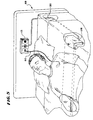
- FIG. 5 there is shown a simplified, perspective, fragmentary view of a bed 68 equipped with a patient's station monitoring housing 13 mounted to the headboard so that the alligator clip 12 (FIGS. 1 and 3) can be fastened to a patient.
- the cord 60 has a length so that if the patient falls from the bed or attempts to leave, the cord 60 will cause either the disk 63 (FIGS. 1 and 4) to be pulled from the housing 13 or the pressure pad 11 B receive less weight and generate a signal.
- the pressure pad is under the shoulders of the patient.
- a message may be played requesting the patient to remain in the bed and/or an alarm may be transmitted to a caretaker who can attend to the matter.
- the cord is 30 inches long.
- FIG. 6 there is shown a simplified, fragmentary, partly-perspective and partly-schematic view of a portion 16 of one possible embodiment of the patient monitoring system 10 having the first length of the cord 60, the station alarm 14, the pressure pad sensor conductor 30, and an OR gate 44 connected so that when the magnetic shunt 63 is pulled free from the housing 13, the reed relay 73 closes about the power supply 69 to send a signal through the conductor 61 to the station control and interface system 15 to provide an alarm signal and when the weight on one of the pressure pads is released, a signal is sent through conductor 30 through the station control and interface system 15 to provide an alarm.
- the station control and interface system 15 performs the "OR" function within the microprocessor 94 or by a separate "O" gate before the microprocessor.
- the housing includes a permanent magnet or an energized electrode magnet 71, a reed relay 73, and ferromagnetic path members 75, 77 and 79.
- the ferromagnetic path members 75, 77 and 79 form a closed ferromagnetic circuit with the magnet 71.
- This ferromagnetic circuit maintains the normally open reed relay 73 in its open position.
- the magnetic shunt 63 is ferromagnetic, and when seated so that it rests on the members 75 and 79, forms a ferromagnetic shunt that diverts flux away from the member 77, thus permitting the reed relay 73 to close.
- FIG. 7 is a block diagram of the control system for an embodiment of the invention and has its principle parts a microprocessor 94, a transmitter 98, an alarm speaker 112, a nurse call 96 and a voice microprocessor 90.
- the microprocessor 94 is a type PIC16C54 Microcontroller sold by Microchip Technology, Inc. of Arizona. It's an 18-pin microprocessor having an input 102 for tone select, an input 104 for another tone select, an input 106 for local alert and 108 for local voice to set the microprocessor 94.
- a flag is set in the microprocessor 94.
- the microprocessor 94 transmits an alarm signal to the nurse call station 96, the transmitter 98 and the alarm speaker 112 within two and one-half seconds unless the pressure is again applied to the sensing pad. If set for that purpose, a signal may be sent to the voice microprocessor 90. This provides the warning to the patient.
- a signal from the station control and interface system 15 (FIG. 6) or similar component in other circuit arrangement from other sensors indicating that the first sensor which is the magnetic shunt 63 has been pulled free initiates an alarm signal.
- FIG. 8 there is shown a flow diagram of a program utilizable in the microprocessor 94 (FIG. 7) to determine an alarm condition using a pressure pad which program includes a start step 120, a wake-up or power starting and initializing step 122, an alarm condition detecting step 124, a timer step 126 and a go to start step 128.
- the microprocessor 94 (FIG. 7) is initialized such as at the step 122 and determines if there is an alarm condition caused by the shunt being removed or the pressure pad being armed and removed, determines if there is an alarm condition on the pad if it lasts for approximately 2.5 seconds and returns to start step 128.
- the alarm condition detecting step 124 includes the steps of determining if the shunt is pulled at step 130, providing an alarm signal as shown at 132 if it has been pulled, and if it has not been pulled, going to the decision step 134.
- the decision step 134 determines if the pad is present and if it is, the program proceeds to the arm the pad step 136 by applying a pressure pad flag if pressure has been applied to the pressure pad to reduce resistance. If the pad is not present, then the program proceeds to the decision step 138 to determine if there is an armed pad flag, and if there is, then it proceeds to the step 140 to provide an alarm. If not, it proceeds to the timer step 126 and from there back to the start step 120 from the go to start step 128. If the armed pad flag 136 is set as a result of the pad being present and weight being upon it then the program proceeds to the timer step 126 and from there back through steps 120, 122, 130, 134, 138 and alarm step 140.
- FIG. 9 there is shown a schematic block diagram of the microprocessor circuitry 94 connected to the pad 11A.
- the pad is energized by a source of voltage 150 and applied to the pad 11A through a resistor 152.
- a comparator 154 has its noninverting input terminal energized by the battery source 150 through an adjustable resistor 156 that determines a threshold value for the pad that can be set to accommodate the weight and size of a person on the pad.
- the pad provides the signal as determined by 150 and controlled by the resistance of the pad 11A to the inverting terminal of the comparator 154 to initiate a timer 158, which may be within the microprocessor or separate from the microprocessor.
- the microprocessor If this condition as determined by the comparator 154 lasts for approximately 2.5 seconds then the microprocessor provides an alarm signal. But if the threshold from the pad 11A as applied to the comparator 154 falls at the noninverting input terminal, then the timer 158 is reset and no alarm is given.
- the patient monitoring system of this invention has several advantages, such as for example: (1) it provides redundancy so that if one alarm fails the other may succeed to provide a warning alarm; (2) it permits the selection of one or more sensing conditions and combinations of different types of sensors such as one that locates the distance that the patient has moved and another that indicates that the patient has lifted himself or herself off of a pressure pad or has swung his or her legs over the edge of a bed or has applied a substantial amount of his or her weight to a support for lifting his or herself from a bed or wheelchair; (3) it can detect distress conditions that might otherwise be missed such as for example a cord indicating a patient is leaving the bed or wheelchair or has fallen from it and a release-of-pressure sensor that indicates the patient may be thrashing about within the length of the cord or dangling from the bed or chair without exceeding the length of the cord; (4) it is difficult for the patient to defeat; and (5) it is relatively flexible in the conditions to be sensed, the nature of the alarm or alarms or the warnings or messages to
Abstract
Description
- This invention relates to patient monitoring systems and more particularly to patient monitoring systems in which the movement or location of a patient is determined by any of a plurality of redundant or cooperating sensors and when one or more of the sensors indicates a problem with the patient provides an alarm or a warning.
- In one class of patient monitoring systems, a sensor indicates the departure of a patient from his or her expected position and the system responds by providing an alarm. In one such system, a fastener is connected to a monitoring housing by a cord or other device having a fixed length so that if the fastener moves beyond that length, the monitoring housing is activated. The fastener is connected to a patient such as to the clothing of a patient by a clip so that, if the patient moves beyond a fixed distance such as by slumping from a wheelchair onto the floor or moving from a bed, the monitoring housing provides an alarm.
- In a prior art monitoring system of this type, the end of the cord opposite to the fastener is loosely fitted into the monitoring housing so that, when the patient moves away from the monitoring housing so that, when the patient moves away from the monitoring housing a distance greater that the length of the cord, that end is pulled free. When the end is pulled free from the monitoring housing, an alarm is given. Prior art system of this type are disclosed in United States Patents 4,577,185,4,858,622, and 4,583,084 and systems of this type are on sale under the trademark, TABS, by Wanderguard, Inc., a division of Senior Technologies, Inc., located at 1620 North 20th Street, P.O. Box 80238, Lincoln, NE 68503.
- This type of prior art patient monitoring system has several disadvantages, such as for example: (1) from time to time the fastener falls loose from the patient or is removed by the patient so that the system fails; (2) the patient may become entangled in bedding or the like or fall from the bed or chair or partly fall at a distance that does not pull the cord free; and (3) the cord may break or be cut.
- In another class of patient monitoring systems, the patient in a bed or a wheelchair rests on or near a pressure pad. Changes in pressure on that pad cause a signal indicating that the patient is moving in a manner that indicates some type of problem. In a prior art monitoring system of this type, a manual switch is activated by an attendant or patient when the patient is in place to initiate the monitoring system and inactivated when the patient leaves in an ordinary untroublesome manner. One such prior art system is disclosed in United States Patent 4,907,845.
- This type of prior art monitoring system has several disadvantages such as for example: (1 ) the switch may be accidentally thrown or thrown by a patient intending to move but for whom it is undesirable to move unattended because of confusion of the patient or illness to the extent that the patient does not appreciate; (2) because the pressure pad is positioned in the bed beneath the patient, it flexes as the patient moves, causing the cord to flex, eventually fail and thus prevent the signal being given if the patient leaves; and (3) the pad may be defeated by folding or placing a weight on it.
- Accordingly, a novel patient monitoring system is provided with at least two sensing modalities that cooperate so that it is difficult for the patient to defeat either intentionally or accidentally, and which can be set and reset without patient-accessible switches.
- Accordingly, a method of monitoring a patient wherein a first sensor is placed in juxtaposition with a patient so that when the patient assumes a dangerous position as indicated by the first sensor an alarm signal is given; a monitoring station is activated when the alarm signal is provided and a voice message is announced in the vicinity of the patient, characterized in that a second sensor is also positioned in juxtaposition with the patient and provides an alarm signal when the patient assumes a dangerous position.
- Advantageously, one of the first and second sensors may be armed by the application of weight to it and an alarm is provided to a caretaker. In the preferred embodiment the alarm is in the vicinity of the patient but may be at a remote station. One of said first and second sensors may be a pressure pad.
- In one embodiment the patient is monitored by attaching a fastening means to a patient, wherein if the patient moves beyond a predetermined distance, a first switch moves between one of an open state or a closed state to the other of the open or closed state; placing a pressure pad under the patient that activates a second switch when energized; providing an alarm signal when either the first switch or the second switch is activated wherein the pressure pad is activated by removal of pressure and reset by application of pressure. Advantageously, the fastening means is attached to the clothing of the patient and a verbal message may be provided to the patient. The alarm may be provided to a caretaker at the remote station.
- The equipment for monitoring the patient includes a control housing mounted to a patient station; a flexible member attached to the control housing; said flexible member including a fastening means on one end for attaching to the patient and a switch on the other end; characterized by a pressure pad located so that the pressure pad is under the patient; wherein the control housing including a means for providing an alarm signal when the fastening means or pressure pad are activated. A pressure pad is activated by removal of pressure and inactivated by application of pressure and the fastening means includes a spring means for biasing jaws in a closed position.
- The alarm includes a recorded voice message sounding within hearing distance of the patient to which said fastening means has been attached. There may be a patient characterized by having first and second sensors; the first sensor sensing one of the motion, distance, location or weight of the patient and the second sensor sensing a different one of the motion, distance, location or weight of the patient, either said first or second sensors being able to trigger an alarm. Moreover, pressure pad means for responding to pressure by reducing electrical resistance between a first point and a second point may be provided along with switch means armed upon the reduction of electrical resistance; an alarm means for providing an alarm when the switch means has been armed characterized in that electrical resistance is over the predetermined threshold for more than 1 second, wherein the movement of the patient from the pad triggers an alarm. Similarly, the alarm means may provide an alarm when the switch means has been armed and electrical resistance is over the predetermined threshold for a time between 2 seconds and 3 seconds in duration.
- The patient monitoring system of this invention has several advantages, such as for example: (1) it provides redundancy so that if one alarm fails the other may succeed to provide a warning alarm; (2) it permits the selection of one or more sensing conditions and combinations of different types of sensors such as one that locates the distance that the patient has moved and another that indicates that the patient has lifted himself or herself off of a pressure pad or has swung his or her legs over the edge of a bed or applied a substantial amount of his or her weight to a support for lifting his or herself from a bed or wheelchair; (3) it can detect distress conditions that might otherwise be missed such as for example a cord indicating a patient is leaving the bed or wheelchair or has fallen from it and a release-of-pressure sensor that indicates the patient may be thrashing about within the length of the cord or dangling from the bed or chair without exceeding the length of the cord; (4) it is difficult for the patient to defeat; and (5) it is relatively flexible in the condition or conditions to be sensed and the nature of the alarm or alarms, or the warnings or messages to the patient, or the sequence of the alarms and messages and the location or locations of the alarm with respect to the caretaker of the patient.
- The above noted and other features of the invention will be better understood from the following detailed description when considered in connection with the accompanying drawings, in which:
- FIG. 1 is a simplified perspective view of an embodiment of the invention;
- FIG. 2 is a block diagram of a patient monitoring system in accordance with the invention;
- FIG. 3 is a fragmentary, simplified perspective view showing a manner in which the fastener, a cord and pressure pad are used to monitor a patient;
- FIG. 4 is a fragmentary simplified perspective view illustrating the use of the patient monitoring system in connection with a wheelchair;
- FIG. 5 is a simplified, perspective, fragmentary view illustrating the use of the patient monitoring system in connection with a bed;
- FIG. 6 is a simplified partly perspective and partly schematic view of a portion of the embodiment of FIG. 1;
- FIG. 7 is a block diagram of the control system for an embodiment of the invention;
- FIG. 8 is a flow diagram of the program for determining an alarm condition using a pressure pad; and
- FIG. 9 is a schematic block diagram of a threshold circuit for the pressure pad.
-
- In FIG. 1, there is shown a simplified perspective view of a
patient monitoring system 10 having a wheelchair pressure pad switch 11A a bed pressure pad switch 11B, acord 60 and ahousing 13. A microprocessor (not show in FIG. 1) within thehousing 13 is electrically connected to either one of the wheelchair or bed pad pressure switches 11A and 11 B (first sensor) to cooperate with them and receive a signal when pressure is applied to the pads or released from the pads. The cord switch 34 (second sensor) includes analligator clip 12, acord 60 and amagnetic shunt 63 adapted to fit into aslot 67 in thehousing 13. Thealligator clip 12 is on one end of thecord 60 and theshunt 63 on the other. - The alligator clip or
other connector 12 is fastened to the clothing of the patient and thedisk 63 put into theslot 67. When it is removed such as by the person moving a distance greater than that of thecord 60, an alarm and/or voice is sounded. Similarly, when pressure is placed on either the pad 11A in a wheelchair embodiment or the pad 11B in a bed near the shoulders of a patient, a flag on the microprocessor is set so that when the patient releases the pressure such as by getting up from the seat of the wheelchair or sitting up if on a bed, the microprocessor receives a signal resulting in an alarm or voice message and alarm. - To establish the electrical connections between the pressure pads and microprocessor or to pulse forming equipment or threshold equipment for processing signals for input to the microprocessor within the
housing 13, the pressure pad 11A is connected by anelectrical conductor 65A to theconductor 30 and the bed pressure pad switch 11B is connected by a conductor 65B toconductor 30 with theconductor 65A being shown connected to the conductor in FIG. 1. The input circuits for the microprocessor may be incorporated within thehousing 13 and its role is to develop a signal for the microprocessor when pressure is applied on the pressure pads 11A and 11B, which in the preferred embodiment is a pad that reduces resistance when pressure is placed upon it. Other types of pressure pads are known in the art and any of them may be used but some of them would not require theinput circuit 15 but would generate their own signal. - In the preferred embodiment, the pressure pads are described in United States Patent 5,796,059 to Stephen Boon which are manufactured and available from Micro- Tech Medical, Inc., 17 Rose Avenue, West Hartford, Connecticut 06110 but other types are known such as those disclosed by United States Patents 4,263,586 and 4,020,482. The pressure pad described in the aforementioned United States Patent 5,796,059 is able to provide signals indicating the location on the pad of pressure and thus, with the aid of the microprocessor detect and indicate shifts in position of the patient such as tilting in a wheelchair or moving to the edge of a bed. While in the preferred embodiment the pressure pad is placed under the bedding it can be placed at other locations such as under the mattress. Moreover, it may be used with an analyzer such as a microprocessor to detect direction of movement such as whether a patient is moving toward a door or away from a door by detecting directional changes in pressure.
- In this specification, a sensor includes any device which senses a position or motion or location of the patient. The term sensor not only includes the device for sensing the position, location, movement or the like of the patient but any error correcting or redundant part of it which indicates a failure condition of the sensor itself.
- For example, in United States Patent 5,494,046 an alligator clip is disclosed attached to a cord and a magnetic shunt similar to that of the preferred embodiment of this invention. However, the alligator clip is designed so that while it is fastened to the garment of the patient, it in itself has an open circuit but when removed, it has a closed circuit so that if this particular sensor has been removed from the patient and is thus disabled to not detect if the patient moves beyond the length of the cord from the
housing 13, a signal nonetheless will be provided. However, in this specification it is considered one sensor because it indicates the length of the patient from thehousing 13 or the failure of the sensor to be able to detect such a position of the patient. - In FIG. 2, there is shown a block diagram of a
patient monitoring system 10 having afirst sensor 32, asecond sensor 34, the patient-station monitoring housing 13, astation alarm system 14, a station control andinterface system 15, and aremote station alarm 20. The patient-station monitoring housing 13 may include a voice record system in the manner disclosed in United States Patent 5,494,046 for providing verbal instructions to a patient under certain sensed conditions. As in the case of the system described in United States Patent 5,494,046, the disclosure of which is incorporated herein for reference, an alarm is given at the station with the patient and/or a nurses station before a voice carries a message to the patient so that immediately upon the sensing of an alarm condition, the attendants receive notification and can proceed to the aid of the patient. - In the preferred embodiment, the
second sensor 34 is an alligator clip attached to a cord which moves an object in juxtaposition with thehousing 13 such as a magnetic shunt that can be removed or a magnet that activates a reed switch, either placed inside or outside of thestation alarm unit 14 and thehousing 13 or any other type of sensor, many of which are described in United States Patent 4,494,046 such as photocell sensors that senses the removal of an object from thehousing 13 by uncovering a light path or a mechanical device or any of many sensing devices such that may sense the removal of an object from the interior of thehousing 13 or the surface of thehousing 13. Because the other sensor develops signals with a different criteria it may be used to reset the pad. For example, the pad sensor may be reset by removing and reinserting theplug 63 into theopening 67 rather than using pressure to both reset after a signal and to arm the sensor. - The
station alarm 14 may include a lamp or a buzzer or the like and theremote station 20 may be connected bywires 26 to receive an alarm such as at a remote location such as a nursing station or may have anantenna 24 which receives a signal from the station alarm or transmits a signal to other stations so as to provide an alarm at those stations. The alarms at the remote stations may also be any type of indicator such as a lamp, a buzzing sound, a ringing sound, a horn-like sound, or a voice. - While in the embodiment of FIG. 2, alarms are provided before the message is played both near the patient and at a remote location, the alarm nearby from the station alarm may be omitted and the signal transmitted directly to the remote station or
alarm 20 or the message may be played simultaneously with either or both thestation alarm 14 andremote alarm 20 or before either or both alarms. The voice system may be any standard commercial arrangement such as are now commonly used to play a fixed message. In the preferred embodiment, the voice system is a single chip, voice record/playback device Model ISD14XX sold under the trademark DAST by Information Storage Devices, Inc., 2841 Junction Avenue, Suite 204, San Jose, California, 95134. - In FIG. 3, there is shown a fragmentary, simplified perspective view of a patient 64 wearing a
garment 62 and having the alligator clip orother fastener 12 fastened to thegarment 62 and connected by at least one length ofcord 60 to thehousing 13 at the patient station constituting the second sensor which is acord switch 34 in the embodiment of FIG. 1 and a pressure pad 11A and switch 15 constituting afirst sensor 32. In the preferred embodiment, thealligator clip 12 is fastened by a first length ofcord 60 to a switch member (not shown in FIG. 3) that may be pulled from its position in thehousing 13 to signal an alarm easier than the alligator clip orother fastener 12 is freed from thegarment 62. The pressure pad 1 1A is intended to be on the seat of a wheelchair to provide a signal if the patient leaves the wheelchair. - The length of
cord 60 should be selected for the use but should be within a range of five inches to five feet and preferably within a range of ten inches to twenty inches for a chair and still more preferably 15 inches for a chair. It should be preferably within a range of two feet to three feet for a bed and still more preferably thirty inches. - The alarm switch may be of any type, such as for example the switch disclosed in U.S. Patent 4,160,972, the disclosure of which is incorporated herein by reference when used to activate an alarm when the switch is opened. To activate an alarm when a switch is closed rather than when opened, a source of power in series with the alarm and switch may be used. Moreover, a voice processor 90 (FIG. 7) within the
housing 13 may be used with other types of systems such as that disclosed in U.S. Patent 4,577,185, the disclosure of which is incorporated by reference herein, to activate an alarm when the length ofcord 60 is pulled free from the housing. Thus, thecord 60 may pull a ferromagnetic member away from a reed switch or may pull a mechanical switch closed or open or may move an opaque object from or into a location between a light source and a photocell to change the state of a switch and thus activate a voice recording and one or more alarms. Thealarms 14 and 20 (FIG. 2) may be audible or visual or both. - With this arrangement, if the patient were to move further away from the
housing 13 such as by falling from a chair or leaving a bed, thecord 60 would stretch and pull the magnetic shunt 63 (FIG. 1) or other member, free from the slot 67 (FIG. 1), closing a circuit in thehousing 13 to activate the alarm and/or voice recording. Moreover, if pressure were released on the pads 11A or 11 B a signal would be given to provide an alarm. - The alligator clip or
other fastener 12 is generally fastened to the torso of a patient such as on a shirt or the top part of a hospital gown or the like in the vicinity of the shoulder and thecord 60 is sized in accordance with the location of the monitoring apparatus. For example, in a wheelchair, thecord 60 is generally 18 inches long and in a bed setting it is generally two feet long. It should be no shorter than one foot and no longer than five feet in length. Thehousing 13 is generally fastened to a nearby support. - In FIG. 4, there is shown a fragmentary, simplified perspective view of a
wheelchair 66 showing an appropriate mounting for thehousing 13 above the wheelchair with thecord 60 facing forwardly and being connected to the alligator clip andmagnetic disk 63 in theslot 67 of thehousing 13 so that a patient in the wheelchair may have theclip 12 fastened to the patient's garment. The pressure pad 11A is under the patient's seat so that the patient's weight is upon it. In the preferred embodiment, the cord is fifteen inches long. If the patient then slumps forward out of the chair, thedisk 63 is pulled free from theslot 67 or pressure released on the pressure pad 11A, thehousing 13 provides an alarm signal to a caretaker, preferably at a remote location. The recorded message in an embodiment of this type may request the patient to remain stationary until aid arrives. - In FIG. 5, there is shown a simplified, perspective, fragmentary view of a
bed 68 equipped with a patient'sstation monitoring housing 13 mounted to the headboard so that the alligator clip 12 (FIGS. 1 and 3) can be fastened to a patient. Thecord 60 has a length so that if the patient falls from the bed or attempts to leave, thecord 60 will cause either the disk 63 (FIGS. 1 and 4) to be pulled from thehousing 13 or the pressure pad 11 B receive less weight and generate a signal. The pressure pad is under the shoulders of the patient. In either case, a message may be played requesting the patient to remain in the bed and/or an alarm may be transmitted to a caretaker who can attend to the matter. In the preferred embodiment, the cord is 30 inches long. - In FIG. 6, there is shown a simplified, fragmentary, partly-perspective and partly-schematic view of a portion 16 of one possible embodiment of the
patient monitoring system 10 having the first length of thecord 60, thestation alarm 14, the pressurepad sensor conductor 30, and an OR gate 44 connected so that when themagnetic shunt 63 is pulled free from thehousing 13, thereed relay 73 closes about thepower supply 69 to send a signal through theconductor 61 to the station control andinterface system 15 to provide an alarm signal and when the weight on one of the pressure pads is released, a signal is sent throughconductor 30 through the station control andinterface system 15 to provide an alarm. The station control andinterface system 15 performs the "OR" function within themicroprocessor 94 or by a separate "O" gate before the microprocessor. - In the embodiment of FIG. 6, the housing includes a permanent magnet or an energized
electrode magnet 71, areed relay 73, andferromagnetic path members ferromagnetic path members magnet 71. This ferromagnetic circuit maintains the normallyopen reed relay 73 in its open position. Themagnetic shunt 63 is ferromagnetic, and when seated so that it rests on themembers member 77, thus permitting thereed relay 73 to close. - With this arrangement, when the
disk 63 is pulled free, a signal is transmitted to the station control andinterface system 15 and thestation alarm 14 to initiate the voice message and/or alarm from the voice processor 90 (FIG. 7) of the housing 13 (FIGS. 1, 3, 4 and 5) and the remote station alarm 20 (FIG. 2) as explained in connection with FIG. 2. - FIG. 7 is a block diagram of the control system for an embodiment of the invention and has its principle parts a
microprocessor 94, atransmitter 98, analarm speaker 112, anurse call 96 and avoice microprocessor 90. Themicroprocessor 94 is a type PIC16C54 Microcontroller sold by Microchip Technology, Inc. of Arizona. It's an 18-pin microprocessor having aninput 102 for tone select, aninput 104 for another tone select, aninput 106 for local alert and 108 for local voice to set themicroprocessor 94. - With this arrangement, when an input signal is received from the
conductor 30, a flag is set in themicroprocessor 94. When a signal is received indicating a release of the pressure, themicroprocessor 94 transmits an alarm signal to thenurse call station 96, thetransmitter 98 and thealarm speaker 112 within two and one-half seconds unless the pressure is again applied to the sensing pad. If set for that purpose, a signal may be sent to thevoice microprocessor 90. This provides the warning to the patient. Similarly, a signal from the station control and interface system 15 (FIG. 6) or similar component in other circuit arrangement from other sensors indicating that the first sensor which is themagnetic shunt 63 has been pulled free, initiates an alarm signal. - In FIG. 8, there is shown a flow diagram of a program utilizable in the microprocessor 94 (FIG. 7) to determine an alarm condition using a pressure pad which program includes a start step 120, a wake-up or power starting and initializing
step 122, an alarmcondition detecting step 124, atimer step 126 and a go to startstep 128. With this arrangement, the microprocessor 94 (FIG. 7) is initialized such as at thestep 122 and determines if there is an alarm condition caused by the shunt being removed or the pressure pad being armed and removed, determines if there is an alarm condition on the pad if it lasts for approximately 2.5 seconds and returns to startstep 128. - The alarm
condition detecting step 124 includes the steps of determining if the shunt is pulled atstep 130, providing an alarm signal as shown at 132 if it has been pulled, and if it has not been pulled, going to thedecision step 134. Thedecision step 134 determines if the pad is present and if it is, the program proceeds to the arm thepad step 136 by applying a pressure pad flag if pressure has been applied to the pressure pad to reduce resistance. If the pad is not present, then the program proceeds to thedecision step 138 to determine if there is an armed pad flag, and if there is, then it proceeds to thestep 140 to provide an alarm. If not, it proceeds to thetimer step 126 and from there back to the start step 120 from the go to startstep 128. If thearmed pad flag 136 is set as a result of the pad being present and weight being upon it then the program proceeds to thetimer step 126 and from there back throughsteps alarm step 140. - With this arrangement, an alarm is provided if the shunt is pulled or if the flag is armed and weight is removed for approximately 2.5 seconds.
- In FIG. 9, there is shown a schematic block diagram of the
microprocessor circuitry 94 connected to the pad 11A. The pad is energized by a source ofvoltage 150 and applied to the pad 11A through aresistor 152. Acomparator 154 has its noninverting input terminal energized by thebattery source 150 through anadjustable resistor 156 that determines a threshold value for the pad that can be set to accommodate the weight and size of a person on the pad. The pad provides the signal as determined by 150 and controlled by the resistance of the pad 11A to the inverting terminal of thecomparator 154 to initiate atimer 158, which may be within the microprocessor or separate from the microprocessor. If this condition as determined by thecomparator 154 lasts for approximately 2.5 seconds then the microprocessor provides an alarm signal. But if the threshold from the pad 11A as applied to thecomparator 154 falls at the noninverting input terminal, then thetimer 158 is reset and no alarm is given. - The patient monitoring system of this invention has several advantages, such as for example: (1) it provides redundancy so that if one alarm fails the other may succeed to provide a warning alarm; (2) it permits the selection of one or more sensing conditions and combinations of different types of sensors such as one that locates the distance that the patient has moved and another that indicates that the patient has lifted himself or herself off of a pressure pad or has swung his or her legs over the edge of a bed or has applied a substantial amount of his or her weight to a support for lifting his or herself from a bed or wheelchair; (3) it can detect distress conditions that might otherwise be missed such as for example a cord indicating a patient is leaving the bed or wheelchair or has fallen from it and a release-of-pressure sensor that indicates the patient may be thrashing about within the length of the cord or dangling from the bed or chair without exceeding the length of the cord; (4) it is difficult for the patient to defeat; and (5) it is relatively flexible in the conditions to be sensed, the nature of the alarm or alarms or the warnings or messages to be given, the sequence of the alarms and messages and the location or locations of the alarm with respect to the caretaker or the patient are selectable.
- Although a preferred embodiment of the invention has been described with some particularity, many modifications and variations of the preferred embodiment are possible within the light of the above teachings. Therefore, it is to be understood that, within the scope of the appended claims, the invention may be practiced other than as specifically described.
Claims (17)
- A method of monitoring a patient wherein a second sensor (34, 12, 60) is placed in juxtaposition with a patient (64) so that when the patient (64) assumes a dangerous position as indicated by the second sensor (12, 60) an alarm signal is given; a monitoring station is activated when the alarm signal is provided, and a voice message is announced in the vicinity of the patient, characterized in that a first sensor (11A, 32) is also positioned in juxtaposition with the patient (64) and provides an alarm signal when the patient assumes a dangerous position.
- A method according to claim 1 characterized in that one of the first and second sensors is armed by the application of weight to it.
- A method in accordance with claim 1 or 2 characterized in which an alarm is provided to a caretaker.
- A method in accordance with claim 1 or 2 characterized in that the alarm is in the vicinity of the patient.
- A method in accordance with claim 1 or 2 characterized in that the alarm is at a remote station.
- A method in accordance with any of claims 1-5 characterized in that one of said first and second sensors is a pressure pad.
- A method of monitoring a patient, comprising the steps of: attaching a fastening means (12) to a patient (64), wherein if the patient (64) moves beyond a predetermined distance, a second switch (34) moves between one of an open state or a closed state to the other of the open or closed state; characterized by placing a pressure pad (11A, 11 B) under the patient that activates a first switch when energized; providing an alarm signal when either the first switch or the second switch is activated wherein the pressure pad is activated by removal of pressure and reset by application of pressure.
- A method in accordance with claim 7 characterized by attaching the fastening means to the clothing of the patient.
- A method in accordance with either claim 7 or 8 characterized by providing a verbal message to the patient.
- A method in accordance with any of claims 7, 8 or 9 characterized by transmitting a signal to a remote station and providing an alarm to a caretaker at the remote station.
- Apparatus for monitoring a patient, comprising a control housing mounted (13) to a patient station; a flexible member (60) attached to the control housing; said flexible member including a fastening means (12) on one end for attaching to the patient and a switch (63) on the other end; characterized by a pressure pad (11A, 11 B) located so that the pressure pad is under the patient; wherein the control housing including a means for providing an alarm signal when the fastening means (12) or pressure pad (11A, 11B) are activated.
- Apparatus for monitoring a patient in accordance with claim 11 characterized in that said pressure pad (11A, 11 B) is activated by removal of pressure and inactivated by application of pressure.
- Apparatus in accordance with either claim 11 or 12 characterized in that said fastening means (12) includes a spring means for biasing jaws in a closed position.
- Apparatus in accordance with any of claims 11, 12, or 13 characterized in that said alarm includes a recorded voice message sounding within hearing distance of the patient to which said fastening means has been attached.
- Apparatus for monitoring a patient characterized by having first and second sensors (32, 34); said second sensor (34) sensing one of the motion, distance, location or weight of the patient and the first sensor (32) sensing a different one of the motion, distance, location or weight of the patient, either said first or second sensors being able to trigger an alarm.
- A patient monitoring system, comprising: pressure pad means (11A, 11B) for responding to pressure by reducing electrical resistance between a first point and a second point; switch means armed upon the reduction of electrical resistance; an alarm means for providing an alarm when the switch means has been armed characterized in that electrical resistance is over the predetermined threshold for more than 1 second, wherein the movement of the patient from the pad triggers an alarm.
- A patient monitoring system according to claim 16 characterized in that the alarm means provides an alarm when the switch means has been armed and electrical resistance is over the predetermined threshold for a time between 2 seconds and 3 seconds in duration.
Applications Claiming Priority (2)
| Application Number | Priority Date | Filing Date | Title |
|---|---|---|---|
| US09/151,020 US6166644A (en) | 1998-09-10 | 1998-09-10 | Patient monitoring system |
| US151020 | 1998-09-10 |
Publications (2)
| Publication Number | Publication Date |
|---|---|
| EP0985375A2 true EP0985375A2 (en) | 2000-03-15 |
| EP0985375A3 EP0985375A3 (en) | 2000-06-28 |
Family
ID=22537000
Family Applications (1)
| Application Number | Title | Priority Date | Filing Date |
|---|---|---|---|
| EP99250319A Withdrawn EP0985375A3 (en) | 1998-09-10 | 1999-09-10 | Patient monitoring system |
Country Status (3)
| Country | Link |
|---|---|
| US (2) | US6166644A (en) |
| EP (1) | EP0985375A3 (en) |
| JP (1) | JP2000083909A (en) |
Cited By (6)
| Publication number | Priority date | Publication date | Assignee | Title |
|---|---|---|---|---|
| EP2145581A1 (en) * | 2008-07-17 | 2010-01-20 | General Electric Company | System for providing remote signals from a patient monitor |
| WO2013097653A1 (en) * | 2011-12-30 | 2013-07-04 | 华为终端有限公司 | Bodyguarding method and device |
| DK201700275A1 (en) * | 2017-05-01 | 2018-05-28 | Allan Jacobsen | Elzer Coupling |
| CN111297577A (en) * | 2020-02-19 | 2020-06-19 | 郑州大学体育学院 | Intelligent seat integrating tumble risk prediction and tumble resistance training |
| CN114340490A (en) * | 2019-06-17 | 2022-04-12 | 泰帝产品有限责任公司 | Integrated strap and sensor for patient furniture alarm |
| US11821452B2 (en) | 2017-08-03 | 2023-11-21 | Tidi Products, Llc | Integrated belt and sensor for alarm for patient furniture |
Families Citing this family (77)
| Publication number | Priority date | Publication date | Assignee | Title |
|---|---|---|---|---|
| US7834768B2 (en) | 1999-03-05 | 2010-11-16 | Hill-Rom Services, Inc. | Obstruction detection apparatus for a bed |
| US6791460B2 (en) * | 1999-03-05 | 2004-09-14 | Hill-Rom Services, Inc. | Patient position detection apparatus for a bed |
| EP2319472B1 (en) * | 1999-12-29 | 2016-03-23 | Hill-Rom Services, Inc. | Patient support |
| US6611783B2 (en) | 2000-01-07 | 2003-08-26 | Nocwatch, Inc. | Attitude indicator and activity monitoring device |
| JP4606630B2 (en) * | 2001-03-28 | 2011-01-05 | 綜合警備保障株式会社 | Rise detection device |
| US7022072B2 (en) * | 2001-12-27 | 2006-04-04 | Medtronic Minimed, Inc. | System for monitoring physiological characteristics |
| US6985870B2 (en) | 2002-01-11 | 2006-01-10 | Baxter International Inc. | Medication delivery system |
| US10173008B2 (en) | 2002-01-29 | 2019-01-08 | Baxter International Inc. | System and method for communicating with a dialysis machine through a network |
| US8775196B2 (en) | 2002-01-29 | 2014-07-08 | Baxter International Inc. | System and method for notification and escalation of medical data |
| US6963286B2 (en) * | 2002-02-27 | 2005-11-08 | 210 Innovations Llc | Wheelchair and alarm therefor |
| US8234128B2 (en) | 2002-04-30 | 2012-07-31 | Baxter International, Inc. | System and method for verifying medical device operational parameters |
| US6788206B1 (en) | 2002-09-05 | 2004-09-07 | Donald A. Edwards | Patient monitoring system |
| US6930603B2 (en) * | 2002-11-08 | 2005-08-16 | Ivette Jackson | Sensor light device |
| US6965311B1 (en) | 2002-11-25 | 2005-11-15 | Franklin Charles Karner | Medical alert mat with remoter pager |
| US7026940B2 (en) * | 2003-01-02 | 2006-04-11 | Alimed, Inc. | Chair back monitoring device |
| US6847301B1 (en) | 2003-03-06 | 2005-01-25 | Personal Safety Corporation | Patient position monitoring device |
| US20040178910A1 (en) * | 2003-03-12 | 2004-09-16 | Tekare Investments Inc. | Patient monitoring system |
| US20070118054A1 (en) * | 2005-11-01 | 2007-05-24 | Earlysense Ltd. | Methods and systems for monitoring patients for clinical episodes |
| US8403865B2 (en) | 2004-02-05 | 2013-03-26 | Earlysense Ltd. | Prediction and monitoring of clinical episodes |
| US8942779B2 (en) | 2004-02-05 | 2015-01-27 | Early Sense Ltd. | Monitoring a condition of a subject |
| EP1740143B1 (en) | 2004-04-30 | 2010-08-25 | Hill-Rom Services, Inc. | Patient support |
| US7319386B2 (en) | 2004-08-02 | 2008-01-15 | Hill-Rom Services, Inc. | Configurable system for alerting caregivers |
| US7253366B2 (en) * | 2004-08-09 | 2007-08-07 | Hill-Rom Services, Inc. | Exit alarm for a hospital bed triggered by individual load cell weight readings exceeding a predetermined threshold |
| CA2486949A1 (en) * | 2004-12-09 | 2006-06-09 | Christian Cloutier | System and method for detecting falls and remote monitoring of activity levels in frail individuals |
| ATE545361T1 (en) * | 2004-12-13 | 2012-03-15 | Koninkl Philips Electronics Nv | MOBILE MONITORING |
| US20060152358A1 (en) * | 2005-01-07 | 2006-07-13 | Josef Osterweil | Bed-exit monitoring method and apparatus |
| US20070004971A1 (en) * | 2005-05-27 | 2007-01-04 | Hill-Rom Services, Inc. | Caregiver communication system for a home environment |
| JP5208732B2 (en) | 2005-06-10 | 2013-06-12 | ヒル−ロム サービシーズ,インコーポレイティド | Control means for pressurized bag in patient support device |
| US8117701B2 (en) | 2005-07-08 | 2012-02-21 | Hill-Rom Services, Inc. | Control unit for patient support |
| US7849545B2 (en) | 2006-11-14 | 2010-12-14 | Hill-Rom Industries Sa | Control system for hospital bed mattress |
| US7916036B1 (en) | 2006-12-15 | 2011-03-29 | Stanley Security Solutions, Inc. | Patient position monitor with timer |
| WO2009138976A2 (en) * | 2008-05-12 | 2009-11-19 | Earlysense Ltd | Monitoring, predicting and treating clinical episodes |
| US8063375B2 (en) * | 2007-06-22 | 2011-11-22 | Intel-Ge Care Innovations Llc | Sensible motion detector |
| US8085154B2 (en) * | 2008-02-27 | 2011-12-27 | Smart Caregiver Corporation | Circuit and method for providing an improved bed pad monitor system |
| ATE541512T1 (en) * | 2008-03-14 | 2012-02-15 | Koninkl Philips Electronics Nv | ACTIVITY MONITORING SYSTEM INSENSITIVE TO ACCELERATIONS CAUSED BY EXTERNAL MOTION FACTORS |
| US8882684B2 (en) | 2008-05-12 | 2014-11-11 | Earlysense Ltd. | Monitoring, predicting and treating clinical episodes |
| US9883809B2 (en) | 2008-05-01 | 2018-02-06 | Earlysense Ltd. | Monitoring, predicting and treating clinical episodes |
| US10089443B2 (en) | 2012-05-15 | 2018-10-02 | Baxter International Inc. | Home medical device systems and methods for therapy prescription and tracking, servicing and inventory |
| US8057679B2 (en) | 2008-07-09 | 2011-11-15 | Baxter International Inc. | Dialysis system having trending and alert generation |
| US8593284B2 (en) | 2008-09-19 | 2013-11-26 | Hill-Rom Services, Inc. | System and method for reporting status of a bed |
| US8554579B2 (en) | 2008-10-13 | 2013-10-08 | Fht, Inc. | Management, reporting and benchmarking of medication preparation |
| US8451129B2 (en) * | 2008-11-03 | 2013-05-28 | Medline Industries, Inc. | Patient monitoring system with unitary structure and method |
| US9585562B2 (en) * | 2008-12-03 | 2017-03-07 | Carefusion 303, Inc. | Method and apparatus for automatically integrating a medical device into a medical facility network |
| US8081083B2 (en) * | 2009-03-06 | 2011-12-20 | Telehealth Sensors Llc | Mattress or chair sensor envelope with an antenna |
| US20100225488A1 (en) * | 2009-03-06 | 2010-09-09 | Telehealth Sensors, Llc | Patient Monitoring System Using an Active Mattress or Chair System |
| US20100228516A1 (en) * | 2009-03-06 | 2010-09-09 | Telehealth Sensors, Llc | Electronic mattress or chair sensor for patient monitoring |
| US20120154155A1 (en) * | 2009-03-26 | 2012-06-21 | John Brasch | Personal monitoring system |
| US8350709B2 (en) * | 2010-03-31 | 2013-01-08 | Hill-Rom Services, Inc. | Presence detector and occupant support employing the same |
| US8717181B2 (en) | 2010-07-29 | 2014-05-06 | Hill-Rom Services, Inc. | Bed exit alert silence with automatic re-enable |
| US20120032808A1 (en) * | 2010-08-04 | 2012-02-09 | Alimed, Inc. | Connector for patient monitoring device |
| US8686849B2 (en) * | 2010-08-10 | 2014-04-01 | Robert Bosch Gmbh | Method of alarm handling in wireless sensor networks |
| US10292625B2 (en) * | 2010-12-07 | 2019-05-21 | Earlysense Ltd. | Monitoring a sleeping subject |
| GB2490691A (en) * | 2011-05-10 | 2012-11-14 | Thomas David Cullen | Motion detection device for use in a hospital or retirement home |
| US9827156B2 (en) | 2011-11-11 | 2017-11-28 | Hill-Rom Services, Inc. | Person support apparatus |
| EP2911641B1 (en) | 2012-10-26 | 2018-10-17 | Baxter Corporation Englewood | Improved work station for medical dose preparation system |
| SG11201503190RA (en) | 2012-10-26 | 2015-05-28 | Baxter Corp Englewood | Improved image acquisition for medical dose preparation system |
| US10292605B2 (en) | 2012-11-15 | 2019-05-21 | Hill-Rom Services, Inc. | Bed load cell based physiological sensing systems and methods |
| US9655798B2 (en) | 2013-03-14 | 2017-05-23 | Hill-Rom Services, Inc. | Multi-alert lights for hospital bed |
| US20150305620A1 (en) * | 2014-04-25 | 2015-10-29 | Rondish Company Ltd. | Self-Contained, Wireless Patient Monitoring Pad |
| EP2995242B1 (en) | 2014-09-11 | 2023-11-15 | Hill-Rom S.A.S. | Patient support apparatus |
| US11107574B2 (en) | 2014-09-30 | 2021-08-31 | Baxter Corporation Englewood | Management of medication preparation with formulary management |
| WO2016090091A1 (en) | 2014-12-05 | 2016-06-09 | Baxter Corporation Englewood | Dose preparation data analytics |
| US9466204B2 (en) * | 2014-12-23 | 2016-10-11 | Professional Security Corporation | Patient position monitoring device |
| EP3265989A4 (en) | 2015-03-03 | 2018-10-24 | Baxter Corporation Englewood | Pharmacy workflow management with integrated alerts |
| US11064677B2 (en) * | 2015-06-23 | 2021-07-20 | Matthew Friscia | Lighted pet bed |
| CA2985719C (en) | 2015-06-25 | 2024-03-26 | Gambro Lundia Ab | Medical device system and method having a distributed database |
| US11064912B2 (en) * | 2016-01-26 | 2021-07-20 | Climax Technology Co., Ltd. | Fall sensor |
| US10641013B2 (en) | 2016-02-16 | 2020-05-05 | Go Lock Technology, Inc. | Portable lock with integrity sensors |
| WO2018114346A1 (en) | 2016-12-21 | 2018-06-28 | Gambro Lundia Ab | Medical device system including information technology infrastructure having secure cluster domain supporting external domain |
| WO2018129178A1 (en) | 2017-01-04 | 2018-07-12 | Golock Technology, Inc. | Cable with integral sensing elements for fault detection |
| US10544605B2 (en) | 2017-05-19 | 2020-01-28 | Douglas A. Yates | Sliding lockable housing with supplemental openings |
| US20190038224A1 (en) * | 2017-08-03 | 2019-02-07 | Intel Corporation | Wearable devices having pressure activated biometric monitoring systems and related methods |
| US11210922B2 (en) | 2018-10-22 | 2021-12-28 | Tidi Products, Llc | Electronic fall monitoring system |
| US10692346B2 (en) * | 2018-10-22 | 2020-06-23 | Tidi Products, Llc | Electronic fall monitoring system |
| CN113272876A (en) * | 2018-11-07 | 2021-08-17 | 史蒂文·戈德梅尔 | Wheelchair foot sensor alarm |
| US11786421B2 (en) * | 2020-09-16 | 2023-10-17 | Toyota Motor North America, Inc. | Wheelchair systems with emergency stop features |
| WO2022231899A1 (en) * | 2021-04-26 | 2022-11-03 | Kp Inventions, Llc | System and method for tracking patient activity |
Citations (8)
| Publication number | Priority date | Publication date | Assignee | Title |
|---|---|---|---|---|
| US4020482A (en) | 1976-04-19 | 1977-04-26 | Feldl Erich J | Patient monitor |
| US4263586A (en) | 1976-08-20 | 1981-04-21 | Noel Nicholas | Pressure operated electric switch and alarm system using such switch |
| US4577185A (en) | 1983-07-29 | 1986-03-18 | Saint Margaret Hospital | Construction for alerting health-care professionals |
| US4583084A (en) | 1984-01-27 | 1986-04-15 | Lutheran General Hospital, Inc. | Patient monitor |
| US4858622A (en) | 1987-04-01 | 1989-08-22 | J.D. Monitoring, Incorporated | Fall alert system with magnetically operable switch |
| US4907845A (en) | 1988-09-16 | 1990-03-13 | Salomon Sa | Bed patient monitoring system |
| US5494046A (en) | 1993-07-07 | 1996-02-27 | Senior Technologies, Inc. | Patient monitoring system |
| US5796059A (en) | 1996-03-19 | 1998-08-18 | Boon; Stephen W. | Pressure-sensitive switch apparatus |
Family Cites Families (10)
| Publication number | Priority date | Publication date | Assignee | Title |
|---|---|---|---|---|
| US4160972A (en) * | 1978-05-18 | 1979-07-10 | Adco Venetian Blind Company | Alarm apparatus for movable barrier members |
| US4196425A (en) * | 1978-07-10 | 1980-04-01 | by said David S. Weekly said Clyde E. Williams | Patient activity monitoring system |
| US4209776A (en) * | 1978-07-24 | 1980-06-24 | Electronic Surveillance Fence Security, Inc. | Vibratory and ultrasonic fence intruder detection system |
| US4638307A (en) * | 1985-10-15 | 1987-01-20 | Swartout Willson C | Patient position monitoring system |
| SE465695B (en) * | 1989-02-22 | 1991-10-14 | Arcus Vita Ab | SINGLE ALARM, SPECIFICALLY PROVIDED TO BE USED FOR PATIENTS IN HOSPITALS AND LIKE, BEFORE MONITORING TO A PATIENT LEAVING HIS BED |
| US5699038A (en) * | 1993-07-12 | 1997-12-16 | Hill-Rom, Inc. | Bed status information system for hospital beds |
| US5600305A (en) * | 1995-09-25 | 1997-02-04 | Stafford; Jerome | Portable patient monitoring system |
| US5751214A (en) * | 1995-12-13 | 1998-05-12 | Alertcare, Inc. | Patient activity monitoring device with multiple sensors |
| US5701117A (en) * | 1996-01-18 | 1997-12-23 | Brian Page Platner | Occupancy detector |
| US5767774A (en) * | 1997-04-17 | 1998-06-16 | Dwyer Precision Inc. A Division Of Wescom, Inc. | Patient bed exit monitor |
-
1998
- 1998-09-10 US US09/151,020 patent/US6166644A/en not_active Expired - Lifetime
-
1999
- 1999-09-09 JP JP11255150A patent/JP2000083909A/en active Pending
- 1999-09-10 EP EP99250319A patent/EP0985375A3/en not_active Withdrawn
-
2000
- 2000-12-21 US US09/746,294 patent/US20010001237A1/en not_active Abandoned
Patent Citations (8)
| Publication number | Priority date | Publication date | Assignee | Title |
|---|---|---|---|---|
| US4020482A (en) | 1976-04-19 | 1977-04-26 | Feldl Erich J | Patient monitor |
| US4263586A (en) | 1976-08-20 | 1981-04-21 | Noel Nicholas | Pressure operated electric switch and alarm system using such switch |
| US4577185A (en) | 1983-07-29 | 1986-03-18 | Saint Margaret Hospital | Construction for alerting health-care professionals |
| US4583084A (en) | 1984-01-27 | 1986-04-15 | Lutheran General Hospital, Inc. | Patient monitor |
| US4858622A (en) | 1987-04-01 | 1989-08-22 | J.D. Monitoring, Incorporated | Fall alert system with magnetically operable switch |
| US4907845A (en) | 1988-09-16 | 1990-03-13 | Salomon Sa | Bed patient monitoring system |
| US5494046A (en) | 1993-07-07 | 1996-02-27 | Senior Technologies, Inc. | Patient monitoring system |
| US5796059A (en) | 1996-03-19 | 1998-08-18 | Boon; Stephen W. | Pressure-sensitive switch apparatus |
Cited By (7)
| Publication number | Priority date | Publication date | Assignee | Title |
|---|---|---|---|---|
| EP2145581A1 (en) * | 2008-07-17 | 2010-01-20 | General Electric Company | System for providing remote signals from a patient monitor |
| WO2013097653A1 (en) * | 2011-12-30 | 2013-07-04 | 华为终端有限公司 | Bodyguarding method and device |
| DK201700275A1 (en) * | 2017-05-01 | 2018-05-28 | Allan Jacobsen | Elzer Coupling |
| DK179380B1 (en) * | 2017-05-01 | 2018-05-28 | Allan Jacobsen | Elzer Coupling |
| US11821452B2 (en) | 2017-08-03 | 2023-11-21 | Tidi Products, Llc | Integrated belt and sensor for alarm for patient furniture |
| CN114340490A (en) * | 2019-06-17 | 2022-04-12 | 泰帝产品有限责任公司 | Integrated strap and sensor for patient furniture alarm |
| CN111297577A (en) * | 2020-02-19 | 2020-06-19 | 郑州大学体育学院 | Intelligent seat integrating tumble risk prediction and tumble resistance training |
Also Published As
| Publication number | Publication date |
|---|---|
| EP0985375A3 (en) | 2000-06-28 |
| JP2000083909A (en) | 2000-03-28 |
| US20010001237A1 (en) | 2001-05-17 |
| US6166644A (en) | 2000-12-26 |
Similar Documents
| Publication | Publication Date | Title |
|---|---|---|
| US6166644A (en) | Patient monitoring system | |
| US20020067273A1 (en) | Patient monitoring system | |
| US5494046A (en) | Patient monitoring system | |
| US10332377B2 (en) | Person support apparatuses with patient mobility monitoring | |
| US4638307A (en) | Patient position monitoring system | |
| US4858622A (en) | Fall alert system with magnetically operable switch | |
| US5914660A (en) | Position monitor and alarm apparatus for reducing the possibility of sudden infant death syndrome (SIDS) | |
| US6315740B1 (en) | Seizure and movement monitoring apparatus | |
| US5469146A (en) | Device for attaching to and detecting wetness in diapers | |
| US5844488A (en) | Bed sensor and alarm | |
| US5008654A (en) | Patient ambulation motion detector | |
| US6975230B1 (en) | Method and apparatus for registering movement patterns of human beings | |
| US5400012A (en) | Breathing monitor | |
| US7916036B1 (en) | Patient position monitor with timer | |
| JPH0371131B2 (en) | ||
| KR20180116330A (en) | Patient movements and incontinence notification devices | |
| US4675659A (en) | Method and apparatus for signaling attempted suicide | |
| US5066943A (en) | Patent monitoring system | |
| US20040201487A1 (en) | Alarm | |
| US11179509B2 (en) | System and method for detecting dialysis needle dislodgment | |
| AU2010101280A4 (en) | Sensor pad for bed monitor and system | |
| JP2010017492A (en) | Leaving-bed and wandering detecting device | |
| NL1008136C2 (en) | Method and device for registering movement patterns of people. | |
| JP2867895B2 (en) | Bedtime equipment | |
| AU737561B2 (en) | Sensor arrangement for monitoring physical activity |
Legal Events
| Date | Code | Title | Description |
|---|---|---|---|
| PUAI | Public reference made under article 153(3) epc to a published international application that has entered the european phase |
Free format text: ORIGINAL CODE: 0009012 |
|
| AK | Designated contracting states |
Kind code of ref document: A2 Designated state(s): DE FR GB |
|
| AX | Request for extension of the european patent |
Free format text: AL;LT;LV;MK;RO;SI |
|
| PUAL | Search report despatched |
Free format text: ORIGINAL CODE: 0009013 |
|
| AK | Designated contracting states |
Kind code of ref document: A3 Designated state(s): AT BE CH CY DE DK ES FI FR GB GR IE IT LI LU MC NL PT SE |
|
| AX | Request for extension of the european patent |
Free format text: AL;LT;LV;MK;RO;SI |
|
| 17P | Request for examination filed |
Effective date: 20001221 |
|
| AKX | Designation fees paid |
Free format text: DE FR GB |
|
| 17Q | First examination report despatched |
Effective date: 20030908 |
|
| STAA | Information on the status of an ep patent application or granted ep patent |
Free format text: STATUS: THE APPLICATION IS DEEMED TO BE WITHDRAWN |
|
| 18D | Application deemed to be withdrawn |
Effective date: 20040319 |
|
| REG | Reference to a national code |
Ref country code: HK Ref legal event code: WD Ref document number: 1026355 Country of ref document: HK |