EP0984661A2 - Transmitter-receiver having ear-piece type acoustic transducer part - Google Patents
Transmitter-receiver having ear-piece type acoustic transducer part Download PDFInfo
- Publication number
- EP0984661A2 EP0984661A2 EP99123290A EP99123290A EP0984661A2 EP 0984661 A2 EP0984661 A2 EP 0984661A2 EP 99123290 A EP99123290 A EP 99123290A EP 99123290 A EP99123290 A EP 99123290A EP 0984661 A2 EP0984661 A2 EP 0984661A2
- Authority
- EP
- European Patent Office
- Prior art keywords
- signal
- conducted sound
- bone
- pass filter
- circuit
- Prior art date
- Legal status (The legal status is an assumption and is not a legal conclusion. Google has not performed a legal analysis and makes no representation as to the accuracy of the status listed.)
- Granted
Links
Images


Classifications
-
- H—ELECTRICITY
- H04—ELECTRIC COMMUNICATION TECHNIQUE
- H04R—LOUDSPEAKERS, MICROPHONES, GRAMOPHONE PICK-UPS OR LIKE ACOUSTIC ELECTROMECHANICAL TRANSDUCERS; DEAF-AID SETS; PUBLIC ADDRESS SYSTEMS
- H04R1/00—Details of transducers, loudspeakers or microphones
- H04R1/46—Special adaptations for use as contact microphones, e.g. on musical instrument, on stethoscope
-
- H—ELECTRICITY
- H04—ELECTRIC COMMUNICATION TECHNIQUE
- H04R—LOUDSPEAKERS, MICROPHONES, GRAMOPHONE PICK-UPS OR LIKE ACOUSTIC ELECTROMECHANICAL TRANSDUCERS; DEAF-AID SETS; PUBLIC ADDRESS SYSTEMS
- H04R3/00—Circuits for transducers, loudspeakers or microphones
- H04R3/005—Circuits for transducers, loudspeakers or microphones for combining the signals of two or more microphones
-
- H—ELECTRICITY
- H04—ELECTRIC COMMUNICATION TECHNIQUE
- H04R—LOUDSPEAKERS, MICROPHONES, GRAMOPHONE PICK-UPS OR LIKE ACOUSTIC ELECTROMECHANICAL TRANSDUCERS; DEAF-AID SETS; PUBLIC ADDRESS SYSTEMS
- H04R2460/00—Details of hearing devices, i.e. of ear- or headphones covered by H04R1/10 or H04R5/033 but not provided for in any of their subgroups, or of hearing aids covered by H04R25/00 but not provided for in any of its subgroups
- H04R2460/13—Hearing devices using bone conduction transducers
Definitions
- the present invention relates to a transmitter-receiver which comprises an ear-piece type acoustic transducing part having a microphone and a receiver formed as a unitary structure and a transmitting-receiving circuit connected to the acoustic transducing part and which permits hands-free communications. More particularly, the invention pertains to a transmitter-receiver which has an air-conducted sound pickup microphone and a bone-conducted sound pickup.
- this kind of transmitter-receiver employs, as its ear-piece or ear-set type acoustic transducing part, means which picks up vibrations of the skull caused from talking sound by an acceleration pickup set in the auditory canal (which means will hereinafter be referred to also as a bone-conducted sound pickup microphone and the speech sending signal picked up by this means will hereinafter be referred to as a "bone-conducted sound signal”), or (2) means which guides a speech or talking sound as vibrations of air by a sound pickup tube extending to the vicinity of the mouth and picks up the sound by a microphone set on an ear (which means will hereinafter be referred to also as an air-conducted sound pickup microphone and the speech sending signal picked up by this means will hereinafter be referred to as an "air-conducted sound signal").
- Such a conventional transmitter-receiver of the type which sends speech through utilization of bone conduction is advantageous in that it can be used even in a high-noise environment and permits hands-free communications.
- this transmitter-receiver is not suited to ordinary communications because of its disadvantages that the clarity of articulation of the transmitted speech is so low that the listener cannot easily identify the talker, that the clarity of articulation of the transmitted speech greatly varies from person to person or according to the way of setting the acoustic transducing part on an ear, and that an abnormal sound as by the friction of cords is also picked up.
- the transmitter-receiver of the type utilizing air conduction is more excellent in clarity than the above but has defects that it is inconvenient to handle when the sound pickup tube is long and that the speech sending signal is readily affected by ambient noise when the tube is short.
- the air-conducted sound pickup microphone picks up sounds having propagated through the air, and hence has a feature that the tone quality of the picked-up speech signals is relatively good but is easily affected by ambient noise.
- the bone-conducted sound pickup microphone picks up a talker's vocal sound transmitted through the skull into the ear set, and hence has a feature that the tone quality of the picked-up speech signal is relatively low because of large attenuation of components above 1 to 2 kHz but that the speech signal is relatively free from the influence of ambient noise.
- a transmitter-receiver assembly for sending excellent speech (acoustic) signals through utilization of the merits of such air-conducted sound pickup microphone and bone-conducted sound pickup microphone, there is disclosed in Japanese Utility Model Registration Application Laid-Open No. 206393/89 a device according to the prior art portion of claim 1 that mixes the speech signal picked up by the air-conducted sound pickup microphone and the speech signal picked up by the bone-conducted sound pickup microphone.
- the speech signals from the bone conduction type microphone and the air conduction type microphone are both applied to a low-pass filter and a high-pass filter which have a cutoff frequency of 1 to 2 kHz, then fed to variable attenuators and combined by a mixer into a speech sending signal.
- a low-pass filter and a high-pass filter which have a cutoff frequency of 1 to 2 kHz
- variable attenuators and combined by a mixer into a speech sending signal.
- the SN ratio of the speech sending signal can be improved by decreasing the attenuation of the bone-conducted sound signal from the low-pass filter and increasing the attenuation of the air-conducted sound signal from the high-pass filter through manual control.
- the speech sending signal is substantially composed only of the bone-conducted sound signal components, and hence is extremely low in tone quality.
- the attenuation control by the variable attenuator is manually effected by an ear set user and the user does not monitor the speech sending signal; hence, it is almost impossible to set the attenuation to the optimum value under circumstances where the amount of noise varies.
- a bone-conducted sound composed principally of low-frequency components and an air-conducted sound composed principally of high-frequency components are mixed together to generate the speech sending signal and the ratio of mixing the sounds is made variable in accordance with the severity of ambient noise or an abnormal sound picked up by the bone-conducted sound pickup microphone; therefore, it is possible to implement the transmitter-receiver which makes use of the advantages of the conventional bone-conduction communication device that it can be used in a high-noise environment and permits hands-free communications and which, at the same time, obviates the defects of the conventional bone-conduction communication device, such as low articulation or clarity of speech and discomfort by abnormal sounds.
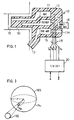
- FIG. 1 there is schematically illustrated the configuration of an ear-piece type acoustic transducing part 10 for use in an embodiment of the present invention.
- Reference numeral 11 denotes a case of the ear-piece type acoustic transducing part 10 wherein various acoustic transducers described later are housed, 12 a lug or protrusion for insertion into the auditory canal 50, and 13 a sound pickup tube for picking up air-conducted sounds.
- the sound pickup tube 13 is designed so that it faces the user's mouth when the lug 12 is put in the auditory canal 50; that is, it is adapted to pick up sounds only in a particular direction.
- the lug 12 and the sound pickup tube 13 are formed as a unitary structure with the case 11.
- Reference numeral 14 denotes an acceleration pickup (hereinafter also referred to as a bone-conducted sound microphone) for picking up bone-conducted sounds, and 15 a directional microphone for picking up air-conducted sounds (i.e. an air-conducted sound pickup microphone), which has such directional characteristics that its sensitivity is high in the direction of the user's mouth (i.e. in the direction of the sound pickup tube 13).
- the directional microphone 15 has its directivity defined by the combining of sound pressure levels of a sound picked up from the front of the microphone 15 and a sound picked up from behind through a guide hole 11. Accordingly, the directivity could also be obtained even if the sound pickup tube 13 is removed to expose the front of the directional microphone 15 in the surface of the case 11.
- Reference numeral 16 denotes an omnidirectional microphone for detecting noise, which has a sound pickup aperture or opening in the direction opposite to the directional microphone 15.
- Reference numeral 17 denotes an electro-acoustic transducer (hereinafter referred to as a receiver) for transducing a received speech signal into a sound, and 18 lead wires for interconnecting the acoustic transducing part 10 and a transmitting-receiving circuit 20 described later; the transmitting-receiving circuit 20 has its terminals T A , T B , T C and T D connected via the lead wires 18 to the directional microphone 15, the bone-conducted pickup sound microphone 14, the receiver 17 and the omnidirectional microphone 16, respectively.
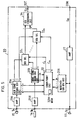
- Fig. 2 there is shown in block form the configuration of the transmitting-receiving circuit 20 which is connected to the acoustic transducing part 10 exemplified in Fig. 1.
- terminals T A , T B , T C and T D are connected to those T A , T B , T C and T D in Fig. 1, respectively.
- Reference numeral 21B denotes an amplifier for amplifying a bone-conducted sound signal from the microphone 14, and 21A an amplifier for amplifying an air-conducted sound signal from the directional, microphone 15.
- the gains of the amplifiers 21B and 21A are preset so that their output speech signal levels during a no-noise period are of about the same order at the inputs of a comparison/control circuit 24 described later.
- Reference numeral 21U denotes an amplifier which amplifies a noise signal from the noise detecting omnidirectional microphone 16 and whose gain is preset so that its noise output during a silent period becomes substantially the same as the noise output level of the amplifier 21A in a noise suppressor circuit 23 described later.
- the amplifiers 21A and 21B and the noise suppressor circuits 23 constitute a noise suppressing part 20N.
- the noise suppressor circuit 23 substantially cancels the noise signal by adding together the outputs from the amplifiers 21A and 21U after putting them 180° out of phase to each other.
- Reference numeral 22B denotes a low-pass filter (LPF), which may preferably be one that approximates characteristics inverse to the frequency characteristics of the microphone 14 used; but it may be a simple low-pass filter of a characteristic such that it cuts the high-frequency components of the output signal from the amplifier 21B but passes therethrough the low-frequency components, and its cutoff frequency is selected within the range of 1 to 2 kHz.
- LPF low-pass filter
- Reference numeral 22A denotes a high-pass filter (HPF), which may preferably be one that approximates characteristics inverse to the frequency characteristics of the directional microphone 15; but it may be a simple high-pass filter of a characteristic such that it cuts the low-frequency components of the output signal from the noise suppressor circuit 23 and passes therethrough the high-frequency components, and its cutoff frequency is selected within the range of 1 to 2 kHz.
- HPF high-pass filter
- the directional microphone 15 and the omnidirectional microphone 16 bear such a relationship of sensitivity characteristic that the former has a high sensitivity within a narrow azimuth angle but the latter substantially the same in all directions as indicated by ideal sensitivity characteristics 15S and 16S in Fig. 3, respectively.
- the ambient noise level is the same in any directions and at any positions
- the noise energy per unit time applied to the omnidirectional microphone 16 from all directions be represented by the surface area N U of a sphere with a radius r
- the noise energy per unit time applied to the directional microphone 15 is represented by an area N A defined by the spreading angle of its directional characteristic on the surface of the sphere.
- their energy ratio N A /N U takes a value sufficiently smaller than one.
- the bone-conducted sound signal and the air-conducted sound signal which have their frequency characteristics equalized by the low-pass filter 22B and the high-pass filter 22A, respectively, are applied to the comparison/control circuit 24, wherein their levels V B and V A are compared with predetermined reference levels V RB and V RA , respectively. Based on the results of comparison, the comparison/control circuit 24 controls losses L B and L A of variable loss circuits 25B and 25A, thereby controlling the levels of the bone- and air-conducted sound signals.
- a mixer circuit 26 mixes the bone-conducted sound signal and the air-conducted sound signal having passed through the variable loss circuits 25B and 25A.
- the thus mixed signal is provided as a speech sending signal S T to a speech sending signal output terminal 20T via a variable loss circuit 29T.
- a comparison/control circuit 28 compares the level of a speech receiving signal S R and the level of the speech sending signal S T with predetermined reference levels V RR and V RT , respectively, and, based on the results of comparison, controls the losses of variable loss circuits 29T and 29R, thereby controlling the levels of the speech sending signal and the speech receiving signal to suppress an echo or howling.
- the speech receiving signal from the variable loss circuit 29R is amplified by an amplifier 27 to an appropriate level and then applied to the receiver 17 via the terminal T C .
- Fig. 4 is a table for explaining the control operations of the comparison/control circuit 24 in Fig. 2.
- the comparison/control circuit 24 compares the output level V B of the low-pass filter 22B and the output level V A of the high-pass filter 22A with the predetermined reference levels V RB and V RA , respectively, and determines if the bone- and air-conducted sound signals are present (white circles) or absent (crosses), depending upon whether the output levels are higher or lower than the reference levels.
- V B of the low-pass filter 22B and the output level V A of the high-pass filter 22A with the predetermined reference levels V RB and V RA , respectively, and determines if the bone- and air-conducted sound signals are present (white circles) or absent (crosses), depending upon whether the output levels are higher or lower than the reference levels.
- state 1 indicates a state in which the bone-conducted sound signal (the output from the low-pass filter 23B) and the air-conducted sound signal (the output from the high-pass filter 23A), both frequency-equalized, are present at the same time, that is, a speech sending or talking state.
- state 2 indicates a state in which the bone-conducted sound signal is present but the air-conducted sound signal is absent, that is, a state in which the microphone 14 is picking up abnormal sounds such as wind noise of the case 11 and frictional sounds by the lead wires 18 and the human body or clothing.
- State 3 indicates a state in which the air-conducted sound signal is present but the bone-conducted sound signal is absent, that is, a state in which no speech signal is being sent and the noise component of the ambient sound picked up by the directional microphone 15 which has not been canceled by the noise suppressor circuit 23 is being outputted.
- State 4 indicates a state in which neither of the bone-and air-conducted sound signals is present, that is, a state in which no speech signal is being sent and no noise is present.
- the control operations described in the right-hand columns of the Fig. 4 table show the operations which the comparison/control circuit 24 performs with respect to the variable loss circuits 25B and 25A in accordance with the above-mentioned states 1 to 4, respectively.
- the bone-conducted sound has many low-frequency components, makes less contribution to articulation and contains, in smaller quantity, high-frequency components which are important for the expression of consonants.
- abnormal sounds such as wind noise by the wind blowing against the case 11 and frictional sound between the cords (lead wires) 18 and the human body or clothing are present in lower and higher frequency bands than the cutoff frequencies of the filters 22A and 22B.
- Such wind noise and frictional sounds constitute contributing factors to the lack of articulation of the speech sending sound by the bone conduction and the formation of abnormal sounds.
- "speech” passes through the sound pickup tube 13 and is picked up as an air-conducted sound signal by the directional microphone 15, from which it is applied to the amplifier 21A via the terminal T A .
- the air-conducted sound by a talker's speech is a human voice itself, and hence contains frequency components spanning low and high frequency bands.
- the high-frequency components of the bone-conducted sound from the amplifier 21B are removed by the low-pass filter 22B to extract the low-frequency components alone and this bone-conducted sound signal having the high-frequency components thus cut out therefrom is mixed with an air-conducted sound signal having cut out therefrom the low-frequency components by the high-pass filter 22A.
- a speech sending signal is generated which has compensated for the degradation of the articulation which would be caused by the lack of the high-frequency components when the speech sending signal is composed only of the bone-conducted sound signal.
- the processing for the generation of such a speech sending signal is automatically controlled to be optimal in accordance with each of the states shown in Fig. 4, by which it is possible to generate a speech sending signal of the best tone quality on the basis of time-varying ambient noise and the speech transmitting-receiving state.
- the noise levels at the directional microphone 15 and the omnidirectional microphone 16 can be regarded as about the same level as referred to previously; but, because of a difference in their directional sensitivity characteristic, the directional microphone 15 picks up a smaller amount of noise energy than does the omnidirectional microphone 16, and hence provides a higher SN ratio. Since the gains G A and G U of the amplifiers 21A and 21U are predetermined so that their output noise levels become nearly equal to each other as mentioned previously, the gain G A of the amplifier 21A is kept sufficiently larger than the gain G U of the amplifier 21U. Hence, the user's speech signal is amplified by the amplifier 21A with the large gain G A and takes a level higher than the noise signal level.
- the comparison/control circuit 24 compares, at regular time intervals (1 sec, for instance), the outputs from the low-pass filter 22B (for the bone-conducted sound) and the high-pass filter 22A (for the air-conducted Sound) with the reference levels V RB and V RA , respectively, to perform such control operations as shown in Fig. 4.
- the characteristic of the transmitter-receiver of the present invention immediately after its assembling is adjusted (or initialized) by setting the losses L B and L A of the variable loss circuits 25B and 25A to initial values L BO and L AO so that the level of the air-conducted sound signal to be input into the mixer 26 is higher than the level of the bone-conducted sound signal by 3 to 10 dB when no noise is present (State 4 in Fig. 4).
- the reason for this is that it is preferable in terms of articulation that the air-conducted sound be larger than the bone-conducted one under circumstances where no noise is present.
- the comparison/control circuit 24 decides that the state is the talking state, and causes the variable loss circuits 25B and 25A to hold losses set in the state immediately preceding State 1.
- the mixer circuit 26 which provides the speech sending signal S T .
- variable loss circuits 29T and 29R and the comparison/control circuit 28 are provided to suppress the generation of an echo and howling which result from the coupling of the speech sending system and the speech receiving system.
- the ear-piece type acoustic transducing part 10 has the following two primary contributing factors to the coupling which leads to the generation of howling. First, when the transmitter-receiver assembly is applied to a telephone set, a two-wire/four-wire junction at a telephone station allows the speech sending signal to sneak as an electrical echo into the speech receiving system from the two-wire/four-wire junction, providing the coupling (sidetone) between the two systems.
- a speech receiving signal is picked up by the bone-conducted sound pickup microphone 14 or directional microphone 15 as a mechanical vibration from the receiver 17 via the case 11--this also provides the coupling between the two systems.
- Such phenomena also occur in a loudspeaking telephone system which allows its user to communicate through a microphone and a loudspeaker without the need of holding a handset.
- the cause of the sneaking of the received sound into the speech sending system is not the mechanical vibration but the acoustic coupling between the microphone and the speaker through the air.
- the configuration by the comparison/control circuit 28 and the variable loss circuits 29T and 29R is an example of such a prior art.
- the comparison/control circuit 28 monitors the output level V T of the mixer circuit 26 and the signal level V R at a received speech input terminal 20R and, when the speech receiving signal level V R is larger than a predetermined level V RR and the output level V T of the mixer circuit 26 is smaller than a predetermined level V RT , the circuit 28 decides that the transmitter-receiver is in the speech receiving state, and sets a predetermined loss L T in the variable loss circuit 29T, reducing the coupling of the speech receiving signal to the speech sending system.
- the comparison/control circuit 28 decides that the transmitter-receiver is in the talking state, and sets a predetermined loss L R in the variable loss circuit 29R, suppressing the sidetone from the speech receiving system.
- the comparison/control circuit 28 decides that the transmitter-receiver is in a double-talk state, and sets in the variable loss circuits 29T and 29R losses one-half those of the above-mentioned predetermined values L T and L R , respectively. In this way, speech with great clarity can be sent to the other party in accordance with the severity of ambient noise and the presence or absence of abnormal noise.
- a mixture of the bone-conducted sound signal composed principally of low-frequency components and the air-conducted sound signal composed principally of high-frequency components is used as the speech signal that is sent to the other party.
- the ratio of mixture of the two signals is automatically varied with the magnitude of ambient noise and the abnormal sound picked up by the microphone 14.
- the comparison/control circuit 24 and the variable loss circuits 25A and 25B may be dispensed with, and even in such a case, the noise level can be appreciably suppressed by the operations of the directional microphone 15, the omnidirectional microphone 16 and the amplifiers 21A and 21B and the noise suppressor circuit 23 which form the noise suppressing part 20N; hence, it is possible to obtain a transmitter-receiver of higher speech quality than in the past.
- the omnidirectional microphone 16, the amplifier 21U and the noise suppressor circuit 23 may be omitted, and in this case, too, the processing for the generation of the optimum speech sending signal can automatically be performed by the operations of the comparison/control circuit 24, the variable loss circuits 25A and 25B and the mixer circuits 26 in accordance with the states of signals involved.
- Fig. 5 illustrates in block form the transmitter-receiver according to the second embodiment of the invention.
- the bone-conducted sound pickup microphone 14, the directional microphone 15 and the receiver 17 are provided in such an ear-piece type acoustic transducing part 10 as depicted in Fig. 1.
- the air-conducted sound signal from the directional microphone (the air-conducted sound pickup microphone 15 and the bone-conducted sound signal from the bone-conducted sound pickup microphone 14 are fed to an air-conducted sound dividing circuit 31A and a bone-conducted sound dividing circuit 31B via the amplifiers 21A and 21B of the transmitting-receiving circuit 20, respectively.
- Fig. 5 illustrates in block form the transmitter-receiver according to the second embodiment of the invention.
- the bone-conducted sound pickup microphone 14, the directional microphone 15 and the receiver 17 are provided in such an ear-piece type acoustic transducing part 10 as depicted in Fig. 1.
- the gains of the amplifiers 21A and 21B are preset so that input air-and bone-conducted sound signals of a vocal sound uttered in a no-noise environment may have about the same level.
- the air-conducted sound dividing circuit 31A divides the air-conducted sound signal from the directional microphone 15 into first through n-th frequency bands and applies the divided signals to a comparison/control circuit 32 and signal select circuits 33 1 through 33 n .
- the bone-conducted sound dividing circuit 31B divides the bone-conducted sound signal from the bone-conducted sound pickup microphone 14 into first through n-th frequency bands and applies the divided signals to the comparison/control circuit 32 and the signal select circuits 33 1 through 33 n .
- a received signal dividing circuit 31R divides the received signal S R from an external line circuit via the input terminal 20R into first through n-th frequency bands and applies the divided signal to the comparison/control circuit 32.
- the comparison/control circuit 32 is such one that converts each input signal into a digital signal by an A/D converter (not shown), and performs such comparison and control operations by a CPU (not shown) as described below.
- the comparison/control circuit 32 calculates an estimated value of the ambient noise level for each frequency band on the basis of the air-conducted sound signals of the respective bands from the air-conducted sound dividing circuit 31A, the bone-conducted sound signals of the respective bands from the bone-conducted sound dividing circuit 31B and the received signals of the respective bands from the received signal dividing circuit 31R.
- the comparison/control circuit 32 compares the estimated values of the ambient noise levels with a predetermined threshold value (i.e. a reference value for selection) N th and generates control signals C1 to Cn for the respective bands on the basis of the results of comparison.
- the control signals C1 to Cn thus produced are applied to the signal select circuits 33 1 to 33 n , respectively.
- the signal select circuits 33 1 to 33 n respond to the control signals C1 to Cn to select the air-conducted sound signals input from the air-conducted sound dividing circuit 31A or the bone-conducted sound signals from the bone-conducted sound signal dividing circuit 31B, which are provided to a signal combining circuit 34.
- the signal combining circuit 34 combines the input speech signals of the respective frequency bands, taking into account the balance between the respective frequency bands, and provides the combines signal to the speech transmitting output terminal 20T.
- the output terminal 20T is a terminal which is connected to an external line circuit.
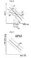
- Fig. 6 is a graph showing, by the solid lines 3A and 3B, a standard or normal relationship between the tone quality (evaluated in terms of the SN ratio or subjective evaluation) of the air-conducted sound signal picked up by the directional microphone 15 and the ambient noise level and a standard or normal relationship between the tone quality of the bone-conducted sound signal picked up by the bone-conducted sound pickup microphone and the ambient noise level.
- the ordinate represents the tone quality of the sound signals (the SN ratio in the circuit, for instance) and the abscissa the noise level.
- the tone quality of the air-conducted sound signal picked up by the directional microphone 15 is greatly affected by the ambient noise level; the tone quality is seriously degraded when the ambient noise level is high.
- the tone quality of the bone-conducted sound signal picked up by the bone-conducted sound pickup microphone 14 is relatively free from the influence of the ambient noise level; degradation of the tone quality by the high noise level is relatively small.
- the speech sending signal S T of good tone quality can be generated by setting the noise level at the intersection of the two solid lines 3A and 3B as the threshold value N th and by selecting either one of the air-conducted sound signal picked up by the directional microphone 15 and the bone-conducted sound signal picked up by the bone-conducted sound pickup microphone, depending upon whether the ambient noise level is higher or lower than the threshold value N th . It was experimentally found that the threshold value N th is substantially in the range of 60 to 80 dBA.
- the characteristics indicated by the solid lines 3A and 3B in Fig. 6 are standard; the characteristics vary within the ranges defined by the broken lines 3A' and 3B' in dependence upon the characteristics of the microphones 14 and 15, the preset gains of the amplifiers 21A and 21B and the frequency characteristics of the input speech signals, but they remain in parallel to the solid lines 3A and 3B, respectively.
- the solid lines 3A and 3B are substantially straight.
- the relationship between the tone quality of the air-conducted sound signal by the directional micropohone 15 and the ambient noise level and the relationship between the tone quality of the bone-conducted sound signal by the bone-conducted sound pickup microphone 14 and the ambient noise level differ with the respective frequency bands.
- the sound signals are each divided into respective frequency bands and either one of the air- and bone-conducted sound signals is selected depending upon whether the measured ambient noise level is higher or lower than a threshold value set for each frequency band--this provides improved tone quality of the speech sending signal.
- Fig. 7 is a graph showing, by the solid line 4BA, a standard relationship of the ambient noise level (on the abscissa) to the level ratio (on the ordinate) between an ambient noise signal picked up by the directional microphone 15 and an ambient noise signal by the bone-conducted sound pickup microphone 14 in the listening or speech receiving or silent duration.
- Fig. 7 is a graph showing, by the solid line 4BA, a standard relationship of the ambient noise level (on the abscissa) to the level ratio (on the ordinate) between an ambient noise signal picked up by the directional microphone 15 and an ambient noise signal by the bone-conducted sound pickup microphone 14 in the listening or speech receiving or silent duration.
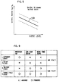
- FIG. 8 is a graph showing, by the solid line 5BA, a standard relationship of the ambient noise level to the level ratio between a signal (the air-conducted sound signal plus the ambient noise signal) picked up by the directional microphone 15 and a signal (the bone-conducted sound signal plus the ambient noise signal) by the bone-conducted sound pickup microphone 15 in the talking or double-talking duration.
- the characteristic in the listening or silent duration and the characteristic in the talking or double-talking duration differ from each other.
- the level V A of the air-conducted sound signal from the directional microphone 15, the level V B of the bone-conducted sound signal from the bone-conducted sound pickup microphone 15 and the level V R of the received signal from the amplifier 27 are compared with the reference level values V RA , V RB and V RR , respectively, to determine if the transmitter-receiver is in the listening (or silent) state or in the talking (or double-talking) state.
- the level ratio V B /V A between the bone-conducted sound signal and the air-conducted sound signals picked up by the microphones 14 and 15 in the listening or silent state is calculated, and the noise level at that time is estimated from the level ratio through utilization of the straight line 4BA in Fig. 7.
- the signal select circuits 33 1 to 33 n each select the bone-conducted sound signal or air-conducted sound signal.
- the level ratio V B /V A between the bone-conducted sound signal and the air-conducted sound signal in the talking or double-talking duration is calculated, then the noise level at that time is estimated from the straight line 5BA in Fig. 8, and the bone-conducted sound signal or air-conducted sound signal is similarly selected depending upon whether the estimated noise level is above or below the threshold value N th .
- the operation of the transmitter-receiver will be described. Incidentally, let is be assumed that there are prestored in a memory 32M of the comparison/control circuit 32 the reference level values V RA , V RB and V RR , the threshold value N th and the level ratio vs. noise level relationships shown in Figs. 7 and 8. Since the speech signals and the received signals divided into the first through n-th frequency bands are subjected to exactly the same processing until they are input into the signal combining circuit 34, the processing in only one frequency band will be described using reference numerals with no suffixes indicating the band.
- the comparison/control circuit 32 compares, at regular time intervals (of one second, for example), the levels V A , V B and V R of the air-conducted sound signal, the bone-conducted sound signal and the received signal input from the air-conducted sound dividing circuit 31A, the bone-conducted sound dividing circuit 31B and the received signal dividing circuit 31R with the predetermined reference level values V RA , V RB and V RR , respectively.
- the comparison/control circuit 32 determines that this state is the listening state shown in the table of Fig. 9.
- the circuit 32 determines that this state is the silent state.
- the comparison/control circuit 32 calculates the level ratio V B /V A between the air-conducted sound signal from the air-conducted sound dividing circuit 31A and the bone-conducted sound signal from the bone-conducted sound dividing circuit 31B. Based on the value of this level ration, the comparison/control circuit 32 refers to the relationship of Fig. 7 stored in the memory 32M to obtain an estimated value of the corresponding ambient noise level. When the estimated value of the ambient noise level is smaller than the threshold value N th shown in Fig. 6, the comparison/control circuit 32 supplies the signal select circuit 33 with a control signal C instructing it to select and output the air-conducted sound signal input from the air-conducted sound dividing circuit 31A.
- the comparison/control circuit 32 applied th control signal C to the signal select circuit 33 to instruct it to select and output the bone-conducted sound signal input from the bone-conducted sound dividing circuit 31B.
- the comparison/control circuit 32 determines that this state is the talking state shown in the table of Fig. 9.
- the comparison/control circuit 32 determines that this state is the double-talking state. In these two states the comparison/control circuit 32 calculates the level ratio V B /V A between the bone-conducted sound signal and the air-conducted sound signal and estimates the ambient noise level N through utilization of the relationship of Fig. 8 stored in the memory 32M.
- the comparison/control circuit 32 applies the control signal C to the signal select circuit 33 to cause it to select and output the air-conducted sound signal input from the air-conducted sound dividing circuit 31A.
- the circuit 32 applies the control signal C to the signal select circuit 33 to cause it to select and output the bone-conducted sound signal input from the bone-conducted sound dividing circuit 31B.
- the comparison/control circuit 32 has, in the memory 32M for each of the first through n-th frequency bands, the predetermined threshold value N th shown in Fig. 6 and the level ratio vs. noise level relationships representing the straight characteristic lines 4BA and 5BA shown in Figs. 7 and 8.
- the comparison/control circuit 32 performs the same processing as mentioned above and applies the resulting control signals C1 to Cn to the signal select circuits 33 1 to 33 n .
- the signal combining circuit 34 combines the speech signals from the signal select circuits 33 1 to 33 n , taking into account the balance between the respective frequency bands.
- the double-talking duration and the silent duration are shorter than the talking or listening duration. Advantage may also be taken of this to effect control in the double-talking state and in the silent state by use of the ambient noise level estimated prior to these states.
- the level of the bone-conducted sound signal picked up by the bone-conducted sound pickup microphone 14 is abnormally high, it can be considered that noise is made by the friction of cords or the like; hence, it is effective to select the air-conducted sound signal picked up by the directional microphone 15.
- the timbre of the speech being sent may sometimes undergo an abrupt change, making the speech unnatural.
- an area N W of a fixed width as indicated by N - and N + is provided about the threshold value N th of the ambient noise level shown in Fig.
- the air-conducted sound signal from the directional microphone 15 and the bone-conducted sound signal from the bone-conducted sound pickup microphone 14 are mixed in a ratio corresponding to the noise level, and when the estimated noise level N is larger than the area N W , the bone-conducted sound signal is selected, and when the estimated noise level is smaller than the area N W , the air-conducted sound signal is selected.
- the modification of the Fig. 5 embodiment for such signal processing can be effected by using, for example, a signal mixer circuit 33 depicted in Fig. 10A in place of each of the signal select circuits 33 1 to 33 n .
- the corresponding air-conducted sound signal and bone-conducted sound signal of each frequency band are applied to variable loss circuits 33A and 33B, respectively, wherein they are given losses L A and L B set by control signals C A and C B from the comparison/control circuit 32.
- the both signals are mixed in a mixer 33C and the mixed signal is applied to the signal combining circuit 34 in Fig. 5.
- the losses L A and L B for the air-conducted sound signal and the bone-conducted sound signal in the area N W need only to be determined as shown in Fig. 10B, for instance.
- N th (N + + N - )/2
- the area width to D N + - N -
- the loss L A in the area N W can be expressed, for example, by the following equation.
- L B L MAX 1 2 + N-N th D
- the value of the maximum loss L MAX is selected in the range of between 20 and 40 dB, and the width D of the area N W is set to about 20 dB, for instance.
- the air-conducted sound signal is not given the loss L MAX but instead the variable loss circuit 33A is opened to cut off the signal.
- the comparison/control circuit 32 determines the losses L A and L B for each band as described and sets the losses in the variable loss circuits 33A and 33B by the control signals C A and C B .
- the signal processing as described above it is possible to provide smooth timbre variations of the speech being sent when the air-conducted sound signal is switched to the bone-conducted sound signal or vice versa. Moreover, if the levels of the air-conducted sound signal and the bone-conducted sound signal input into the variable loss circuits 33A and 33B are nearly equal to each other, the output level of the mixer 33C is held substantially constant before and after the switching between the air- and bone-conducted sound signals and the output level in the area N W is also held substantially constant, ensuring smooth signal switching.
- the signal select circuits 33 1 to 33 n also contribute to the mixing of signals on the basis of the estimated noise level.
- the estimation of the ambient noise level when the estimation of the ambient noise level may be rough, it can be estimated by using average values of the characteristics shown in Figs. 7 and 8. In this instance, the received signal dividing circuit 31R can be dispensed with. When the estimation of the ambient noise level may be rough, it can also be estimated by using only the speech signal from the directional microphone 14.
- Fig. 11 illustrates in block form a modified form of the Fig. 5 embodiment, in which as is the case with the first embodiment of Figs. 1 and 2, the omnidirectional microphone 16, the amplifier 21U and the noise suppressing circuit 23 are provided in association with the direction microphone 15 and the output from the noise suppressing circuit 23 is fed as an air-conducted sound signal to the air-conducted sound dividing circuit 31A.
- This embodiment is identical in construction with the Fig. 5 embodiment except the above.
- the comparison/control circuit 32 estimates the ambient noise levels through utilization of the relationships shown in Fig. 7 and, based on the estimated levels, generate the control signals C1 to Cn for signal selection (or mixing use in the case of using the Fig. 10A circuit configuration), which are applied to the signal select circuits 33 1 to 33 n (or the signal mixing circuit 36).
- the switch 35 is turned ON to pass therethrough the air-conducted sound signal from the directional microphone 15 to the noise suppressing circuit 23, in which its noise components are suppressed, and then the air-conducted sound signal is fed to the air-conducted sound dividing circuit 31A.
- the speech sending signal processing by the same signal selection or mixing as described previously with respect to Fig. 5.
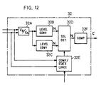
- the comparison/control circuit 32 may also be formed as an analog circuit, for example, as depicted in Fig. 12.
- Fig. 12 there is shown in block form only a circuit portion corresponding to one of the divided subbands.
- a pair of corresponding subband signals from the air-conducted sound signal dividing circuit 31A and the bone-conducted sound signal dividing circuit 31B are both applied to a level ratio circuit 32A and a comparison/logic state circuit 32E.
- the level ratio circuit 32A calculates the level ratio L B /L A between the bone- and air-conducted sound signals in an analog fashion and supplies level converter circuits 32B and 32C with a signal of a level corresponding to the calculated level ratio.
- the level converter circuit 32B performs a level conversion based on the relationship shown in Fig. 7. That is, when supplied with the level ratio V B /V A , the level converter circuit 32B outputs an estimated noise level N corresponding thereto and provides it to a select circuit 32D.
- the level converter circuit 32C performs a level conversion based on the relationship shown in Fig. 8. That is, when supplied with the level ratio V B /V A , the level converter circuit 32C outputs an estimated noise level corresponding thereto and provides it to the select circuit 32D.
- the comparison/state logic circuit 32E compares the levels of the corresponding air- and bone-conducted sound signals of the same subband and the level of the received speech signal with the reference levels V RA , V RB and V RR , respectively, to make a check to see if these signals are present. Based on the results of these checks, the comparison/state logic circuit 32E applies a select control signal to the select circuit 32D to cause it to select the output from the level converter circuit 32B in the case of State 1 or 2 shown in the table of Fig. 9 and the output from the level converter circuit 32C in the case of State 3 or 4.
- the select circuit 32D supplies a comparator circuit 32F with the estimated noise level N selected in response to the select control signal.
- the comparator circuit 32F compares the estimated noise level N with the threshold level N th and provides the result of the comparison, as a control signal C for the subband concerned, to the corresponding one of the signal select circuits 311 to 31n in Fig. 5 or 11. In this instance, it is also possible to make a check to determine if the estimated noise level N is within the area N W or high or lower than it as described previously with respect to Fig.
- the control signals C A and C B corresponding to the difference between the estimated noise level N and the threshold level N th , as is the case with Eqs. (5) and (6), are applied to the signal mixing circuit of the Fig. 10A configuration to cause it to mix the air-conducted sound signal and the bone-conducted sound signal; when the estimated noise level N is higher than the area N W , the bone-conducted sound signal is selected and when the estimated noise level N is lower than the area N W , the air-conducted sound signal is selected.
- the air-conducted sound signal picked up by the directional microphone and the bone-conducted sound signal by the bone-conducted sound pickup microphone are used to estimate the ambient noise level and, on the basis of the magnitude of the estimated noise level, either one of the air-conducted sound signal and the bone-conducted sound signal is selected or both of the signals are mixed together, whereby a speech sending signal of the best tone quality can be generated.
- the communication device of the present invention is able to transmit speech sending signals of excellent tone quality, precisely reflecting the severity and amount of ambient noise regardless of whether the device is in the talking or listening state.
- the transmitting-receiving circuit 20 is described to be provided outside the case 11 of the ear-piece type acoustic transducing part 10 and connected thereto via the cord 18, it is evident that the transmitting-receiving circuit 20 may be provided in the case 11 of the acoustic transducing part 10.
Abstract
Description
- The present invention relates to a transmitter-receiver which comprises an ear-piece type acoustic transducing part having a microphone and a receiver formed as a unitary structure and a transmitting-receiving circuit connected to the acoustic transducing part and which permits hands-free communications. More particularly, the invention pertains to a transmitter-receiver which has an air-conducted sound pickup microphone and a bone-conducted sound pickup.
- Conventionally, this kind of transmitter-receiver employs, as its ear-piece or ear-set type acoustic transducing part, means which picks up vibrations of the skull caused from talking sound by an acceleration pickup set in the auditory canal (which means will hereinafter be referred to also as a bone-conducted sound pickup microphone and the speech sending signal picked up by this means will hereinafter be referred to as a "bone-conducted sound signal"), or (2) means which guides a speech or talking sound as vibrations of air by a sound pickup tube extending to the vicinity of the mouth and picks up the sound by a microphone set on an ear (which means will hereinafter be referred to also as an air-conducted sound pickup microphone and the speech sending signal picked up by this means will hereinafter be referred to as an "air-conducted sound signal").
- Such a conventional transmitter-receiver of the type which sends speech through utilization of bone conduction is advantageous in that it can be used even in a high-noise environment and permits hands-free communications. However, this transmitter-receiver is not suited to ordinary communications because of its disadvantages that the clarity of articulation of the transmitted speech is so low that the listener cannot easily identify the talker, that the clarity of articulation of the transmitted speech greatly varies from person to person or according to the way of setting the acoustic transducing part on an ear, and that an abnormal sound as by the friction of cords is also picked up. On the other hand, the transmitter-receiver of the type utilizing air conduction is more excellent in clarity than the above but has defects that it is inconvenient to handle when the sound pickup tube is long and that the speech sending signal is readily affected by ambient noise when the tube is short.
- The air-conducted sound pickup microphone picks up sounds having propagated through the air, and hence has a feature that the tone quality of the picked-up speech signals is relatively good but is easily affected by ambient noise. The bone-conducted sound pickup microphone picks up a talker's vocal sound transmitted through the skull into the ear set, and hence has a feature that the tone quality of the picked-up speech signal is relatively low because of large attenuation of components above 1 to 2 kHz but that the speech signal is relatively free from the influence of ambient noise. As a transmitter-receiver assembly for sending excellent speech (acoustic) signals through utilization of the merits of such air-conducted sound pickup microphone and bone-conducted sound pickup microphone, there is disclosed in Japanese Utility Model Registration Application Laid-Open No. 206393/89 a device according to the prior art portion of claim 1 that mixes the speech signal picked up by the air-conducted sound pickup microphone and the speech signal picked up by the bone-conducted sound pickup microphone.
- According to this device, the speech signals from the bone conduction type microphone and the air conduction type microphone are both applied to a low-pass filter and a high-pass filter which have a cutoff frequency of 1 to 2 kHz, then fed to variable attenuators and combined by a mixer into a speech sending signal. With this configuration, low-frequency noises in the output from the air conduction type microphone which are lower than the cutoff frequency are removed, and it is possible to remove or cancel components higher than the cutoff frequency in the noise which the bone conduction type microphone is likely to pick up, such as frictional noise by the friction between a cord extending from the ear set and the human body or clothing, or wind noise by the wind blowing against the ear set. Moreover, in a high-noise environment, the SN ratio of the speech sending signal can be improved by decreasing the attenuation of the bone-conducted sound signal from the low-pass filter and increasing the attenuation of the air-conducted sound signal from the high-pass filter through manual control.
- With this configuration, however, when the level of noise from the air-conducted sound pickup microphone is high, the frequency components higher than the cutoff frequency need to be appreciably attenuated for the purpose of attenuating the noise, and consequently, the speech sending signal is substantially composed only of the bone-conducted sound signal components, and hence is extremely low in tone quality. Moreover, the attenuation control by the variable attenuator is manually effected by an ear set user and the user does not monitor the speech sending signal; hence, it is almost impossible to set the attenuation to the optimum value under circumstances where the amount of noise varies. Furthermore, it is cumbersome to manually control the ratio of combining the speech signal from the air-conducted sound pickup microphone and the speech signal from the bone-conducted sound pickup microphone.
- It is therefore an object of the present invention to provide a transmitter-receiver which automatically processes the speech sending signal in accordance with use environments (such as the tone quality and the amount of sound) to send speech of the best tone quality.
- This object is achieved with transmitter-receiver as claimed in claim 1. Preferred embodiments are subject-matter of the dependent claims.
- According to the present invention, a bone-conducted sound composed principally of low-frequency components and an air-conducted sound composed principally of high-frequency components are mixed together to generate the speech sending signal and the ratio of mixing the sounds is made variable in accordance with the severity of ambient noise or an abnormal sound picked up by the bone-conducted sound pickup microphone; therefore, it is possible to implement the transmitter-receiver which makes use of the advantages of the conventional bone-conduction communication device that it can be used in a high-noise environment and permits hands-free communications and which, at the same time, obviates the defects of the conventional bone-conduction communication device, such as low articulation or clarity of speech and discomfort by abnormal sounds.
-
- Fig. 1
- is a sectional view illustrating the configuration of an acoustic transducing part for use in a first embodiment of the present invention;
- Fig. 2
- is a block diagram illustrating the construction of a transmitting-receiving circuit connected to the acoustic transducing part in Fig. 1;
- Fig. 3
- is a diagram for explaining the characteristics of a directional microphone and an omnidirectional microphone;
- Fig. 4
- is a table for explaining control operations of a comparison/control circuit 24 shown in Fig. 2;
- Fig. 5
- is a block diagram illustrating a transmitter-receiver according to a second embodiment of the present invention;
- Fig. 6
- is a graph showing the relationship between the tone quality of an air-conducted sound signal and the ambient noise level, and the relationship between the tone quality of a bone-conducted sound signal and the ambient noise level;
- Fig. 7
- is a graph showing the relationship of the ambient noise level to the level ratio between the bone-conducted sound signal and the air-conducted sound signal in the listening or silent state;
- Fig. 8
- is a graph showing the relationship of the ambient noise level to the level ratio between the bone-conducted sound signal and the air-conducted sound signal in the talking or double-talking state;
- Fig. 9
- is a table for explaining operating states of the Fig. 5 embodiment;
- Fig. 10A
- is a blocked diagram showing the construction of a signal mixing circuit which is used as a substitute for each of signal select circuits 331 to 33n in the Fig. 5 embodiment;
- Fig. 10B
- is a graph showing the mixing operation of the circuit shown in Fig. 10A;
- Fig. 11
- is a block diagram illustrating a modified form of the Fig. 5 embodiment; and
- Fig. 12
- is a block diagram showing the comparison/control circuit 32 in Fig. 5 or 11 constructed as an analog circuit.
- In Fig. 1 there is schematically illustrated the configuration of an ear-piece type acoustic transducing part 10 for use in an embodiment of the present invention. Reference numeral 11 denotes a case of the ear-piece type acoustic transducing part 10 wherein various acoustic transducers described later are housed, 12 a lug or protrusion for insertion into the auditory canal 50, and 13 a sound pickup tube for picking up air-conducted sounds. The sound pickup tube 13 is designed so that it faces the user's mouth when the lug 12 is put in the auditory canal 50; that is, it is adapted to pick up sounds only in a particular direction. The lug 12 and the sound pickup tube 13 are formed as a unitary structure with the case 11.
- Reference numeral 14 denotes an acceleration pickup (hereinafter also referred to as a bone-conducted sound microphone) for picking up bone-conducted sounds, and 15 a directional microphone for picking up air-conducted sounds (i.e. an air-conducted sound pickup microphone), which has such directional characteristics that its sensitivity is high in the direction of the user's mouth (i.e. in the direction of the sound pickup tube 13). The directional microphone 15 has its directivity defined by the combining of sound pressure levels of a sound picked up from the front of the microphone 15 and a sound picked up from behind through a guide hole 11. Accordingly, the directivity could also be obtained even if the sound pickup tube 13 is removed to expose the front of the directional microphone 15 in the surface of the case 11.
- Reference numeral 16 denotes an omnidirectional microphone for detecting noise, which has a sound pickup aperture or opening in the direction opposite to the directional microphone 15. Reference numeral 17 denotes an electro-acoustic transducer (hereinafter referred to as a receiver) for transducing a received speech signal into a sound, and 18 lead wires for interconnecting the acoustic transducing part 10 and a transmitting-receiving circuit 20 described later; the transmitting-receiving circuit 20 has its terminals TA, TB, TC and TD connected via the lead wires 18 to the directional microphone 15, the bone-conducted pickup sound microphone 14, the receiver 17 and the omnidirectional microphone 16, respectively.
- In Fig. 2 there is shown in block form the configuration of the transmitting-receiving circuit 20 which is connected to the acoustic transducing part 10 exemplified in Fig. 1. In Fig. 2 terminals TA, TB, TC and TD are connected to those TA, TB, TC and TD in Fig. 1, respectively.
- Reference numeral 21B denotes an amplifier for amplifying a bone-conducted sound signal from the microphone 14, and 21A an amplifier for amplifying an air-conducted sound signal from the directional, microphone 15. The gains of the amplifiers 21B and 21A are preset so that their output speech signal levels during a no-noise period are of about the same order at the inputs of a comparison/control circuit 24 described later. Reference numeral 21U denotes an amplifier which amplifies a noise signal from the noise detecting omnidirectional microphone 16 and whose gain is preset so that its noise output during a silent period becomes substantially the same as the noise output level of the amplifier 21A in a noise suppressor circuit 23 described later. The amplifiers 21A and 21B and the noise suppressor circuits 23 constitute a noise suppressing part 20N. The noise suppressor circuit 23 substantially cancels the noise signal by adding together the outputs from the amplifiers 21A and 21U after putting them 180° out of phase to each other.
- Reference numeral 22B denotes a low-pass filter (LPF), which may preferably be one that approximates characteristics inverse to the frequency characteristics of the microphone 14 used; but it may be a simple low-pass filter of a characteristic such that it cuts the high-frequency components of the output signal from the amplifier 21B but passes therethrough the low-frequency components, and its cutoff frequency is selected within the range of 1 to 2 kHz. Reference numeral 22A denotes a high-pass filter (HPF), which may preferably be one that approximates characteristics inverse to the frequency characteristics of the directional microphone 15; but it may be a simple high-pass filter of a characteristic such that it cuts the low-frequency components of the output signal from the noise suppressor circuit 23 and passes therethrough the high-frequency components, and its cutoff frequency is selected within the range of 1 to 2 kHz.
- The directional microphone 15 and the omnidirectional microphone 16 bear such a relationship of sensitivity characteristic that the former has a high sensitivity within a narrow azimuth angle but the latter substantially the same in all directions as indicated by ideal sensitivity characteristics 15S and 16S in Fig. 3, respectively. Then, assuming that the ambient noise level is the same in any directions and at any positions, and letting the total amount of noise energy per unit time applied to the omnidirectional microphone 16 from all directions be represented by the surface area NU of a sphere with a radius r, the noise energy per unit time applied to the directional microphone 15 is represented by an area NA defined by the spreading angle of its directional characteristic on the surface of the sphere. Hence, their energy ratio NA/NU takes a value sufficiently smaller than one. Now, assume that the amounts of speech energy SA and SU, applied to the directional microphone 15 and the omnidirectional microphone 16 take the same value S, and let the gains of the amplifiers 21A and 21U be represented by GA and GU, respectively. By setting that a value GANA is nearly equal to a value GUNU, noise is substantially canceled by the noise suppressor circuit 23 but the speech signal level at the output of the noise suppressor circuit 23 becomes
- In Fig. 2 the bone-conducted sound signal and the air-conducted sound signal, which have their frequency characteristics equalized by the low-pass filter 22B and the high-pass filter 22A, respectively, are applied to the comparison/control circuit 24, wherein their levels VB and VA are compared with predetermined reference levels VRB and VRA, respectively. Based on the results of comparison, the comparison/control circuit 24 controls losses LB and LA of variable loss circuits 25B and 25A, thereby controlling the levels of the bone- and air-conducted sound signals. A mixer circuit 26 mixes the bone-conducted sound signal and the air-conducted sound signal having passed through the variable loss circuits 25B and 25A. The thus mixed signal is provided as a speech sending signal ST to a speech sending signal output terminal 20T via a variable loss circuit 29T. A comparison/control circuit 28 compares the level of a speech receiving signal SR and the level of the speech sending signal ST with predetermined reference levels VRR and VRT, respectively, and, based on the results of comparison, controls the losses of variable loss circuits 29T and 29R, thereby controlling the levels of the speech sending signal and the speech receiving signal to suppress an echo or howling. The speech receiving signal from the variable loss circuit 29R is amplified by an amplifier 27 to an appropriate level and then applied to the receiver 17 via the terminal TC.
- Fig. 4 is a table for explaining the control operations of the comparison/control circuit 24 in Fig. 2. The comparison/control circuit 24 compares the output level VB of the low-pass filter 22B and the output level VA of the high-pass filter 22A with the predetermined reference levels VRB and VRA, respectively, and determines if the bone- and air-conducted sound signals are present (white circles) or absent (crosses), depending upon whether the output levels are higher or lower than the reference levels. In Fig. 4, state 1 indicates a state in which the bone-conducted sound signal (the output from the low-pass filter 23B) and the air-conducted sound signal (the output from the high-pass filter 23A), both frequency-equalized, are present at the same time, that is, a speech sending or talking state. State 2 indicates a state in which the bone-conducted sound signal is present but the air-conducted sound signal is absent, that is, a state in which the microphone 14 is picking up abnormal sounds such as wind noise of the case 11 and frictional sounds by the lead wires 18 and the human body or clothing. State 3 indicates a state in which the air-conducted sound signal is present but the bone-conducted sound signal is absent, that is, a state in which no speech signal is being sent and the noise component of the ambient sound picked up by the directional microphone 15 which has not been canceled by the noise suppressor circuit 23 is being outputted. State 4 indicates a state in which neither of the bone-and air-conducted sound signals is present, that is, a state in which no speech signal is being sent and no noise is present. The control operations described in the right-hand columns of the Fig. 4 table show the operations which the comparison/control circuit 24 performs with respect to the variable loss circuits 25B and 25A in accordance with the above-mentioned states 1 to 4, respectively.
- Next, a description will be given of the operation of this embodiment of the above construction. When a user of this transmitter-receiver utters a vocal sound with the ear-piece type acoustic transducing part 10 of Fig. 1 put on his or her ear, the vibration of the skull as well as aerial vibration are created by the vibration of the vocal chords. The vibration of the skull is picked up as a bone-conducted sound signal by the microphone 14, from which the signal is provided via the terminal TB to the amplifier 21B. The aerial vibration of the speech is picked up by the directional microphone 15, from which the signal is provided as an air-conducted sound signal to the amplifier 21A via the terminal TA.
- In general, as compared with the air-conducted sound, the bone-conducted sound has many low-frequency components, makes less contribution to articulation and contains, in smaller quantity, high-frequency components which are important for the expression of consonants. On the other hand, abnormal sounds such as wind noise by the wind blowing against the case 11 and frictional sound between the cords (lead wires) 18 and the human body or clothing are present in lower and higher frequency bands than the cutoff frequencies of the filters 22A and 22B. Such wind noise and frictional sounds constitute contributing factors to the lack of articulation of the speech sending sound by the bone conduction and the formation of abnormal sounds. On the other hand, "speech" passes through the sound pickup tube 13 and is picked up as an air-conducted sound signal by the directional microphone 15, from which it is applied to the amplifier 21A via the terminal TA. The air-conducted sound by a talker's speech is a human voice itself, and hence contains frequency components spanning low and high frequency bands.
- In this embodiment, as described in the afore-mentioned Japanese Utility Model Registration Application Laid-Open Gazette, the high-frequency components of the bone-conducted sound from the amplifier 21B are removed by the low-pass filter 22B to extract the low-frequency components alone and this bone-conducted sound signal having the high-frequency components thus cut out therefrom is mixed with an air-conducted sound signal having cut out therefrom the low-frequency components by the high-pass filter 22A. By this, a speech sending signal is generated which has compensated for the degradation of the articulation which would be caused by the lack of the high-frequency components when the speech sending signal is composed only of the bone-conducted sound signal. Besides, according to the present invention, the processing for the generation of such a speech sending signal is automatically controlled to be optimal in accordance with each of the states shown in Fig. 4, by which it is possible to generate a speech sending signal of the best tone quality on the basis of time-varying ambient noise and the speech transmitting-receiving state.
- The noise levels at the directional microphone 15 and the omnidirectional microphone 16 can be regarded as about the same level as referred to previously; but, because of a difference in their directional sensitivity characteristic, the directional microphone 15 picks up a smaller amount of noise energy than does the omnidirectional microphone 16, and hence provides a higher SN ratio. Since the gains GA and GU of the amplifiers 21A and 21U are predetermined so that their output noise levels become nearly equal to each other as mentioned previously, the gain GA of the amplifier 21A is kept sufficiently larger than the gain GU of the amplifier 21U. Hence, the user's speech signal is amplified by the amplifier 21A with the large gain GA and takes a level higher than the noise signal level.
- The comparison/control circuit 24 compares, at regular time intervals (1 sec, for instance), the outputs from the low-pass filter 22B (for the bone-conducted sound) and the high-pass filter 22A (for the air-conducted Sound) with the reference levels VRB and VRA, respectively, to perform such control operations as shown in Fig. 4. At first, the characteristic of the transmitter-receiver of the present invention immediately after its assembling is adjusted (or initialized) by setting the losses LB and LA of the variable loss circuits 25B and 25A to initial values LBO and LAO so that the level of the air-conducted sound signal to be input into the mixer 26 is higher than the level of the bone-conducted sound signal by 3 to 10 dB when no noise is present (State 4 in Fig. 4). The reason for this is that it is preferable in terms of articulation that the air-conducted sound be larger than the bone-conducted one under circumstances where no noise is present.
- Next, a description will be given of the actual state of use in which the levels of the bone- and air-conducted sound signals vary every moment.
- (a) When the output (the bone-conducted sound signal) from the low-pass filter 22B is not
present (State 3 or 4 in Fig. 4):
The comparison/control circuit 24 compares the output level VA of the high-pass filter 22A with
the reference level VRA. When the output from the high-pass filter 22A is smaller than the
reference level VRA (State 4), the comparison/control circuit 24 decides that noise is not present
or small and that no talks are being carried out and sets the losses of the variable loss circuits
25B and 25A to the afore-mentioned initial values LBO and LAO, respectively. When this state
changes to the talking state (State 1), a mixture of the bone-conducted sound signal composed
of low-frequency components and the air-conducted sound signal composed of high-frequency
components is provided as the speech sending signal ST at the output of the mixer circuit 26.Next, when the output level VB of the low-pass filter 22B is smaller than the reference level VRB
and the output level VA of the high-pass filter 22A is larger than the reference level VRA (State 3),
the comparison/control circuit 24 decides that no talks are being carried out and that ambient
noise is large. In this instance, the comparison/control circuit 24 applies a control signal CA to the
variable loss circuit 25A to set its loss LA to a value larger than the initial value LAO in proportion
to the difference between the output level VA of the high-pass filter 22A and the reference level
value VRA as expressed by such an equation as follows:
where K is a predetermined constant and the notation
 x
x represents the smallest integer greater than x. Alternatively, it is possible to increase the loss LA by a constant K on a stepwise basis each time the level difference (VA-VRA) increases by a constant VM, as expressed by the following equation.
- (b) When the output (the bone-conducted sound signal) level VB of the low-pass filter 22B is
larger than the reference level VRB (State 1 or 2 in Fig. 4):
The comparison/control circuit 24 checks the output level VA of the high-pass filter 22A and, if it
is smaller than the reference level VRA (State 2), determines that no talks are being carried out
and that the microphone 14 is picking up abnormal sounds. In such an instance, the
comparison/control circuit 24 applies a control signal CB to the variable loss circuit 25B to set its
loss LB to a value greater than the initial value LBO, in proportion to the difference between the
output level VB of the low-pass filter 22B and the reference level VRA, as expressed by the
following equation.
When the output level VA of the high-pass filter 22A becomes larger than the reference level VRA, that is, when this State 2 changes to the talking state (State 1), the losses of the variable loss circuits 25A and 25B are held unchanged, and hence are kept at the values set in the immediately preceding State 2. An air-conducted sound signal composed of high-frequency components and a bone-conducted sound signal of a level set in accordance with the output level VB of the low-pass filter 22B and composed of low-frequency components are mixed together by the mixer circuit 26. In this instance, it is also possible to hold the loss of the variable loss circuit 25B unchanged and control the loss of the variable loss circuit 25A so that the output level of the mixer circuit 26 may assume the afore-mentioned predetermined fixed value.

-
- Next, when the output level VA of the high-pass filter 22A is larger than the reference level VRA (State 1), the comparison/control circuit 24 decides that the state is the talking state, and causes the variable loss circuits 25B and 25A to hold losses set in the state immediately preceding State 1. As a result, bone- and air-conducted sound signals of levels controlled in accordance with the losses held unchanged are mixed by the mixer circuit 26, which provides the speech sending signal ST.
- Incidentally, the variable loss circuits 29T and 29R and the comparison/control circuit 28 are provided to suppress the generation of an echo and howling which result from the coupling of the speech sending system and the speech receiving system. The ear-piece type acoustic transducing part 10 has the following two primary contributing factors to the coupling which leads to the generation of howling. First, when the transmitter-receiver assembly is applied to a telephone set, a two-wire/four-wire junction at a telephone station allows the speech sending signal to sneak as an electrical echo into the speech receiving system from the two-wire/four-wire junction, providing the coupling (sidetone) between the two systems. Second, a speech receiving signal is picked up by the bone-conducted sound pickup microphone 14 or directional microphone 15 as a mechanical vibration from the receiver 17 via the case 11--this also provides the coupling between the two systems. Such phenomena also occur in a loudspeaking telephone system which allows its user to communicate through a microphone and a loudspeaker without the need of holding a handset. In this instance, however, the cause of the sneaking of the received sound into the speech sending system is not the mechanical vibration but the acoustic coupling between the microphone and the speaker through the air.
- This problem could be solved by known techniques such as a method for the suppression of howling in the loudspeaking telephone system. The configuration by the comparison/control circuit 28 and the variable loss circuits 29T and 29R is an example of such a prior art. The comparison/control circuit 28 monitors the output level VT of the mixer circuit 26 and the signal level VR at a received speech input terminal 20R and, when the speech receiving signal level VR is larger than a predetermined level VRR and the output level VT of the mixer circuit 26 is smaller than a predetermined level VRT, the circuit 28 decides that the transmitter-receiver is in the speech receiving state, and sets a predetermined loss LT in the variable loss circuit 29T, reducing the coupling of the speech receiving signal to the speech sending system. When the output level VT of the mixer circuit 26 is larger than the predetermined level VRT and the input level VR at the speech receiving signal input terminal 20R is lower than the predetermined level VRR, the comparison/control circuit 28 decides that the transmitter-receiver is in the talking state, and sets a predetermined loss LR in the variable loss circuit 29R, suppressing the sidetone from the speech receiving system. When the output level VT of the mixer circuit 26 and the input level VR at the speech receiving signal input terminal 20R are higher than the predetermined levels VRT and VRR, respectively, the comparison/control circuit 28 decides that the transmitter-receiver is in a double-talk state, and sets in the variable loss circuits 29T and 29R losses one-half those of the above-mentioned predetermined values LT and LR, respectively. In this way, speech with great clarity can be sent to the other party in accordance with the severity of ambient noise and the presence or absence of abnormal noise.
- According to the first embodiment described above, a mixture of the bone-conducted sound signal composed principally of low-frequency components and the air-conducted sound signal composed principally of high-frequency components is used as the speech signal that is sent to the other party. Moreover, the ratio of mixture of the two signals is automatically varied with the magnitude of ambient noise and the abnormal sound picked up by the microphone 14. This permits the implementation of a transmitter-receiver which can be used in a high-noise environment, obviates such defects of the prior art as low clarity or articulation and discomfort by abnormal sound, and allows hands-free communications.
- In the embodiment depicted in Figs. 1 and 2, the comparison/control circuit 24 and the variable loss circuits 25A and 25B may be dispensed with, and even in such a case, the noise level can be appreciably suppressed by the operations of the directional microphone 15, the omnidirectional microphone 16 and the amplifiers 21A and 21B and the noise suppressor circuit 23 which form the noise suppressing part 20N; hence, it is possible to obtain a transmitter-receiver of higher speech quality than in the past. Alternatively, the omnidirectional microphone 16, the amplifier 21U and the noise suppressor circuit 23 may be omitted, and in this case, too, the processing for the generation of the optimum speech sending signal can automatically be performed by the operations of the comparison/control circuit 24, the variable loss circuits 25A and 25B and the mixer circuits 26 in accordance with the states of signals involved.
- Next, a detailed description will be given, with reference to Figs. 5 through 9, of a second embodiment of the transmitter-receiver according to the present invention.
- Fig. 5 illustrates in block form the transmitter-receiver according to the second embodiment of the invention. The bone-conducted sound pickup microphone 14, the directional microphone 15 and the receiver 17 are provided in such an ear-piece type acoustic transducing part 10 as depicted in Fig. 1. In this embodiment, the air-conducted sound signal from the directional microphone (the air-conducted sound pickup microphone 15 and the bone-conducted sound signal from the bone-conducted sound pickup microphone 14 are fed to an air-conducted sound dividing circuit 31A and a bone-conducted sound dividing circuit 31B via the amplifiers 21A and 21B of the transmitting-receiving circuit 20, respectively. As is the case with Fig. 2, the gains of the amplifiers 21A and 21B are preset so that input air-and bone-conducted sound signals of a vocal sound uttered in a no-noise environment may have about the same level. The air-conducted sound dividing circuit 31A divides the air-conducted sound signal from the directional microphone 15 into first through n-th frequency bands and applies the divided signals to a comparison/control circuit 32 and signal select circuits 331 through 33n. The bone-conducted sound dividing circuit 31B divides the bone-conducted sound signal from the bone-conducted sound pickup microphone 14 into first through n-th frequency bands and applies the divided signals to the comparison/control circuit 32 and the signal select circuits 331 through 33n. In the present invention, the air- and bone-conducted sound signals need not always be divided (i.e. n = 1), but when divided into frequency bands, they are divided, for example, every one or one-third octave, or into high and low bands, or high, intermediate and low bands.
- A received signal dividing circuit 31R divides the received signal SR from an external line circuit via the input terminal 20R into first through n-th frequency bands and applies the divided signal to the comparison/control circuit 32. In this embodiment, the comparison/control circuit 32 is such one that converts each input signal into a digital signal by an A/D converter (not shown), and performs such comparison and control operations by a CPU (not shown) as described below. That is, the comparison/control circuit 32 calculates an estimated value of the ambient noise level for each frequency band on the basis of the air-conducted sound signals of the respective bands from the air-conducted sound dividing circuit 31A, the bone-conducted sound signals of the respective bands from the bone-conducted sound dividing circuit 31B and the received signals of the respective bands from the received signal dividing circuit 31R. The comparison/control circuit 32 compares the estimated values of the ambient noise levels with a predetermined threshold value (i.e. a reference value for selection) Nth and generates control signals C1 to Cn for the respective bands on the basis of the results of comparison. The control signals C1 to Cn thus produced are applied to the signal select circuits 331 to 33n, respectively. The signal select circuits 331 to 33n respond to the control signals C1 to Cn to select the air-conducted sound signals input from the air-conducted sound dividing circuit 31A or the bone-conducted sound signals from the bone-conducted sound signal dividing circuit 31B, which are provided to a signal combining circuit 34. The signal combining circuit 34 combines the input speech signals of the respective frequency bands, taking into account the balance between the respective frequency bands, and provides the combines signal to the speech transmitting output terminal 20T. The output terminal 20T is a terminal which is connected to an external line circuit.
- Fig. 6 is a graph showing, by the solid lines 3A and 3B, a standard or normal relationship between the tone quality (evaluated in terms of the SN ratio or subjective evaluation) of the air-conducted sound signal picked up by the directional microphone 15 and the ambient noise level and a standard or normal relationship between the tone quality of the bone-conducted sound signal picked up by the bone-conducted sound pickup microphone and the ambient noise level. The ordinate represents the tone quality of the sound signals (the SN ratio in the circuit, for instance) and the abscissa the noise level. As indicated by the solid line 3A, the tone quality of the air-conducted sound signal picked up by the directional microphone 15 is greatly affected by the ambient noise level; the tone quality is seriously degraded when the ambient noise level is high. On the other hand, as indicated by the solid line 3B, the tone quality of the bone-conducted sound signal picked up by the bone-conducted sound pickup microphone 14 is relatively free from the influence of the ambient noise level; degradation of the tone quality by the high noise level is relatively small. Hence, the speech sending signal ST of good tone quality can be generated by setting the noise level at the intersection of the two solid lines 3A and 3B as the threshold value Nth and by selecting either one of the air-conducted sound signal picked up by the directional microphone 15 and the bone-conducted sound signal picked up by the bone-conducted sound pickup microphone, depending upon whether the ambient noise level is higher or lower than the threshold value Nth. It was experimentally found that the threshold value Nth is substantially in the range of 60 to 80 dBA. The characteristics indicated by the solid lines 3A and 3B in Fig. 6 are standard; the characteristics vary within the ranges defined by the broken lines 3A' and 3B' in dependence upon the characteristics of the microphones 14 and 15, the preset gains of the amplifiers 21A and 21B and the frequency characteristics of the input speech signals, but they remain in parallel to the solid lines 3A and 3B, respectively. The solid lines 3A and 3B are substantially straight.
- The relationship between the tone quality of the air-conducted sound signal by the directional micropohone 15 and the ambient noise level and the relationship between the tone quality of the bone-conducted sound signal by the bone-conducted sound pickup microphone 14 and the ambient noise level differ with the respective frequency bands. For this reason, according to this embodiment, the sound signals are each divided into respective frequency bands and either one of the air- and bone-conducted sound signals is selected depending upon whether the measured ambient noise level is higher or lower than a threshold value set for each frequency band--this provides improved tone quality of the speech sending signal.
- To switch between the air- and bone-conducted sound signals in accordance with the ambient noise level, it is necessary to calculate an estimated value of the ambient noise level. Fig. 7 is a graph showing, by the solid line 4BA, a standard relationship of the ambient noise level (on the abscissa) to the level ratio (on the ordinate) between an ambient noise signal picked up by the directional microphone 15 and an ambient noise signal by the bone-conducted sound pickup microphone 14 in the listening or speech receiving or silent duration. Fig. 8 is a graph showing, by the solid line 5BA, a standard relationship of the ambient noise level to the level ratio between a signal (the air-conducted sound signal plus the ambient noise signal) picked up by the directional microphone 15 and a signal (the bone-conducted sound signal plus the ambient noise signal) by the bone-conducted sound pickup microphone 15 in the talking or double-talking duration. As shown in Figs. 7 and 8, the characteristic in the listening or silent duration and the characteristic in the talking or double-talking duration differ from each other. Hence, the level VA of the air-conducted sound signal from the directional microphone 15, the level VB of the bone-conducted sound signal from the bone-conducted sound pickup microphone 15 and the level VR of the received signal from the amplifier 27 are compared with the reference level values VRA, VRB and VRR, respectively, to determine if the transmitter-receiver is in the listening (or silent) state or in the talking (or double-talking) state. Next, the level ratio VB/VA between the bone-conducted sound signal and the air-conducted sound signals picked up by the microphones 14 and 15 in the listening or silent state is calculated, and the noise level at that time is estimated from the level ratio through utilization of the straight line 4BA in Fig. 7. Depending upon whether the estimated noise level is higher or lower than the threshold value Nth in Fig. 6, the signal select circuits 331 to 33n each select the bone-conducted sound signal or air-conducted sound signal. Similarly, the level ratio VB/VA between the bone-conducted sound signal and the air-conducted sound signal in the talking or double-talking duration is calculated, then the noise level at that time is estimated from the straight line 5BA in Fig. 8, and the bone-conducted sound signal or air-conducted sound signal is similarly selected depending upon whether the estimated noise level is above or below the threshold value Nth.
- Next, the operation of the transmitter-receiver will be described. Incidentally, let is be assumed that there are prestored in a memory 32M of the comparison/control circuit 32 the reference level values VRA, VRB and VRR, the threshold value Nth and the level ratio vs. noise level relationships shown in Figs. 7 and 8. Since the speech signals and the received signals divided into the first through n-th frequency bands are subjected to exactly the same processing until they are input into the signal combining circuit 34, the processing in only one frequency band will be described using reference numerals with no suffixes indicating the band.
- The comparison/control circuit 32 compares, at regular time intervals (of one second, for example), the levels VA, VB and VR of the air-conducted sound signal, the bone-conducted sound signal and the received signal input from the air-conducted sound dividing circuit 31A, the bone-conducted sound dividing circuit 31B and the received signal dividing circuit 31R with the predetermined reference level values VRA, VRB and VRR, respectively. When the level VR of the received signal SR is higher than the predetermined value VRR and the level VA of the air-conducted sound signal picked up by the directional microphone 15 and the level VB of the bone-conducted sound signal by the bone-conducted sound pickup microphone 14 are smaller than the predetermined values VRA and VRB, respectively, the comparison/control circuit 32 determines that this state is the listening state shown in the table of Fig. 9. When the level VR of the received signal level VR is smaller than the predetermined value VRR and the levels VA and VB of the air-conducted sound signal and the bone-conducted sound signal are both smaller than the predetermined values VRA and VRB, the circuit 32 determines that this state is the silent state. In these two states the comparison/control circuit 32 calculates the level ratio VB/VA between the air-conducted sound signal from the air-conducted sound dividing circuit 31A and the bone-conducted sound signal from the bone-conducted sound dividing circuit 31B. Based on the value of this level ration, the comparison/control circuit 32 refers to the relationship of Fig. 7 stored in the memory 32M to obtain an estimated value of the corresponding ambient noise level. When the estimated value of the ambient noise level is smaller than the threshold value Nth shown in Fig. 6, the comparison/control circuit 32 supplies the signal select circuit 33 with a control signal C instructing it to select and output the air-conducted sound signal input from the air-conducted sound dividing circuit 31A. When the estimated value of the ambient noise level is greater than the threshold value Nth, the comparison/control circuit 32 applied th control signal C to the signal select circuit 33 to instruct it to select and output the bone-conducted sound signal input from the bone-conducted sound dividing circuit 31B.
- On the other hand, when the received signal level VR is smaller than the reference level value VRR and the levels VA and VB of the air-conducted sound signal by the directional microphone 15 and the bone-conducted sound signal by the bone-conducted sound pickup microphone 14 are larger then the predetermined reference level values VRA and VRB, the comparison/control circuit 32 determines that this state is the talking state shown in the table of Fig. 9. When the received signal level VR is larger than the reference level value VRR and the levels VA and VB of the air-conducted sound signal and the bone-conducted sound signal are larger than the predetermined reference level values VRA and VRB, the comparison/control circuit 32 determines that this state is the double-talking state. In these two states the comparison/control circuit 32 calculates the level ratio VB/VA between the bone-conducted sound signal and the air-conducted sound signal and estimates the ambient noise level N through utilization of the relationship of Fig. 8 stored in the memory 32M.
- When the thus estimated value of the ambient noise level N is smaller than the threshold value Nth shown in Fig. 6, the comparison/control circuit 32 applies the control signal C to the signal select circuit 33 to cause it to select and output the air-conducted sound signal input from the air-conducted sound dividing circuit 31A. When the estimated value N of the ambient noise level is greater than the threshold value Nth, the circuit 32 applies the control signal C to the signal select circuit 33 to cause it to select and output the bone-conducted sound signal input from the bone-conducted sound dividing circuit 31B.
- The comparison/control circuit 32 has, in the memory 32M for each of the first through n-th frequency bands, the predetermined threshold value Nth shown in Fig. 6 and the level ratio vs. noise level relationships representing the straight characteristic lines 4BA and 5BA shown in Figs. 7 and 8. The comparison/control circuit 32 performs the same processing as mentioned above and applies the resulting control signals C1 to Cn to the signal select circuits 331 to 33n. The signal combining circuit 34 combines the speech signals from the signal select circuits 331 to 33n, taking into account the balance between the respective frequency bands.
- While in the above the embodiments have been described to estimate and compare the noise level with the threshold value and control the signal select circuits 331 to 33n accordingly in any state described in the table of Fig. 9, it is also possible to employ a scheme that estimates the noise level only in the silent or listening state and uses the thus estimated noise level to effect control in the talking state and the double-taking state. In such an instance, the characteristic data of Fig. 8 need not be stored in the memory 32M. In contrast to this, the estimation of the noise level may be made only in the talking or double-talking state, in which case the estimated noise level is used for control in the talking or double-talking state. In this instance, the characteristic data of Fig. 7 is not needed.
- Incidentally, the double-talking duration and the silent duration are shorter than the talking or listening duration. Advantage may also be taken of this to effect control in the double-talking state and in the silent state by use of the ambient noise level estimated prior to these states.
- When the level of the bone-conducted sound signal picked up by the bone-conducted sound pickup microphone 14 is abnormally high, it can be considered that noise is made by the friction of cords or the like; hence, it is effective to select the air-conducted sound signal picked up by the directional microphone 15.
- In the case where the estimated noise level N is compared with the threshold value Nth for each frequency band and the air-conducted sound signal picked up by the directional microphone 15 is switched to the bone-conducted sound signal by the bone-conducted sound pickup microphone 14 on the basis of the result of comparison as described previously with reference to the Fig. 5 embodiment, the timbre of the speech being sent may sometimes undergo an abrupt change, making the speech unnatural. To solve this problem, an area NW of a fixed width as indicated by N- and N+ is provided about the threshold value Nth of the ambient noise level shown in Fig. 6; when the estimated noise level N is within the area NW, the air-conducted sound signal from the directional microphone 15 and the bone-conducted sound signal from the bone-conducted sound pickup microphone 14 are mixed in a ratio corresponding to the noise level, and when the estimated noise level N is larger than the area NW, the bone-conducted sound signal is selected, and when the estimated noise level is smaller than the area NW, the air-conducted sound signal is selected. By this, it is possible to reduce the abrupt change in the timbre prior to or subsequent to the switching operation.
- The modification of the Fig. 5 embodiment for such signal processing can be effected by using, for example, a signal mixer circuit 33 depicted in Fig. 10A in place of each of the signal select circuits 331 to 33n. In this example, the corresponding air-conducted sound signal and bone-conducted sound signal of each frequency band are applied to variable loss circuits 33A and 33B, respectively, wherein they are given losses LA and LB set by control signals CA and CB from the comparison/control circuit 32. The both signals are mixed in a mixer 33C and the mixed signal is applied to the signal combining circuit 34 in Fig. 5.
- The losses LA and LB for the air-conducted sound signal and the bone-conducted sound signal in the area NW need only to be determined as shown in Fig. 10B, for instance. For the brevity's sake, setting
- Similarly, the loss LB can be expressed by the following equation.
- The value of the maximum loss LMAX is selected in the range of between 20 and 40 dB, and the width D of the area NW is set to about 20 dB, for instance. When the estimated noise level N is larger than the area NW, the bone-conducted sound signal is given any loss (LB = 0) and is applied intact to the mixer 33C. On the other hand, the air-conducted sound signal is not given the loss LMAX but instead the variable loss circuit 33A is opened to cut off the signal. Similarly, when the estimated noise level N is smaller than the area NW, the air-conducted sound signal is not given any loss (LA = 0) and is fed intact to the mixer 33C, whereas the bone-conducted sound signal is cut off by opening the variable loss circuit 33B. The comparison/control circuit 32 determines the losses LA and LB for each band as described and sets the losses in the variable loss circuits 33A and 33B by the control signals CA and CB.
- With such signal processing as described above, it is possible to provide smooth timbre variations of the speech being sent when the air-conducted sound signal is switched to the bone-conducted sound signal or vice versa. Moreover, if the levels of the air-conducted sound signal and the bone-conducted sound signal input into the variable loss circuits 33A and 33B are nearly equal to each other, the output level of the mixer 33C is held substantially constant before and after the switching between the air- and bone-conducted sound signals and the output level in the area NW is also held substantially constant, ensuring smooth signal switching. Incidentally, the signal select processing by the signal select circuits 331 to 33n in Fig. 5 corresponds to the case where the width D of the area NW is set to zero in the processing in the modified embodiment depicted in Figs. 10A and 10B. Hence, it can be said, in a broad sense, that the signal select circuits 331 to 33n also contribute to the mixing of signals on the basis of the estimated noise level.
- In the above, when the estimation of the ambient noise level may be rough, it can be estimated by using average values of the characteristics shown in Figs. 7 and 8. In this instance, the received signal dividing circuit 31R can be dispensed with. When the estimation of the ambient noise level may be rough, it can also be estimated by using only the speech signal from the directional microphone 14.
- Fig. 11 illustrates in block form a modified form of the Fig. 5 embodiment, in which as is the case with the first embodiment of Figs. 1 and 2, the omnidirectional microphone 16, the amplifier 21U and the noise suppressing circuit 23 are provided in association with the direction microphone 15 and the output from the noise suppressing circuit 23 is fed as an air-conducted sound signal to the air-conducted sound dividing circuit 31A. This embodiment is identical in construction with the Fig. 5 embodiment except the above. In this embodiment, when the transmitter-receiver is in the silent or listening state, a switch 35 is opened and only the air-conducted sound signal provided via the amplifier 21U from the omnidirectional microphone 16 is applied to the noise suppressing circuit 23, from which it is fed intact to the air-conducted sound dividing circuit 31A, and the air-conducted sound signals divided into respective frequency bands are applied to the comparison/control circuit 32. As in the Fig. 5 embodiment, the comparison/control circuit 32 estimates the ambient noise levels through utilization of the relationships shown in Fig. 7 and, based on the estimated levels, generate the control signals C1 to Cn for signal selection (or mixing use in the case of using the Fig. 10A circuit configuration), which are applied to the signal select circuits 331 to 33n (or the signal mixing circuit 36). After this, the switch 35 is turned ON to pass therethrough the air-conducted sound signal from the directional microphone 15 to the noise suppressing circuit 23, in which its noise components are suppressed, and then the air-conducted sound signal is fed to the air-conducted sound dividing circuit 31A. This is followed by the speech sending signal processing by the same signal selection or mixing as described previously with respect to Fig. 5.
- Although in the embodiments of Figs. 5 and 11 the comparison/control circuit 32 has been described to convert the signals input thereto to digital signals and generate the control signals C1 to Cn on the basis of the level ratio-noise level relationships stored in the memory 32M, the comparison/control circuit 32 may also be formed as an analog circuit, for example, as depicted in Fig. 12. In Fig. 12 there is shown in block form only a circuit portion corresponding to one of the divided subbands. A pair of corresponding subband signals from the air-conducted sound signal dividing circuit 31A and the bone-conducted sound signal dividing circuit 31B are both applied to a level ratio circuit 32A and a comparison/logic state circuit 32E. The level ratio circuit 32A calculates the level ratio LB/LA between the bone- and air-conducted sound signals in an analog fashion and supplies level converter circuits 32B and 32C with a signal of a level corresponding to the calculated level ratio.
- The level converter circuit 32B performs a level conversion based on the relationship shown in Fig. 7. That is, when supplied with the level ratio VB/VA, the level converter circuit 32B outputs an estimated noise level N corresponding thereto and provides it to a select circuit 32D. Similarly, the level converter circuit 32C performs a level conversion based on the relationship shown in Fig. 8. That is, when supplied with the level ratio VB/VA, the level converter circuit 32C outputs an estimated noise level corresponding thereto and provides it to the select circuit 32D. On the other hand, the comparison/state logic circuit 32E compares the levels of the corresponding air- and bone-conducted sound signals of the same subband and the level of the received speech signal with the reference levels VRA, VRB and VRR, respectively, to make a check to see if these signals are present. Based on the results of these checks, the comparison/state logic circuit 32E applies a select control signal to the select circuit 32D to cause it to select the output from the level converter circuit 32B in the case of State 1 or 2 shown in the table of Fig. 9 and the output from the level converter circuit 32C in the case of State 3 or 4.
- The select circuit 32D supplies a comparator circuit 32F with the estimated noise level N selected in response to the select control signal. The comparator circuit 32F compares the estimated noise level N with the threshold level Nth and provides the result of the comparison, as a control signal C for the subband concerned, to the corresponding one of the signal select circuits 311 to 31n in Fig. 5 or 11. In this instance, it is also possible to make a check to determine if the estimated noise level N is within the area NW or high or lower than it as described previously with respect to Fig. 10B, instead of comparing the estimated noise level N with the threshold value Nth; if the estimated noise level N is within the area NW, the control signals CA and CB corresponding to the difference between the estimated noise level N and the threshold level Nth, as is the case with Eqs. (5) and (6), are applied to the signal mixing circuit of the Fig. 10A configuration to cause it to mix the air-conducted sound signal and the bone-conducted sound signal; when the estimated noise level N is higher than the area NW, the bone-conducted sound signal is selected and when the estimated noise level N is lower than the area NW, the air-conducted sound signal is selected.
- As described above, according to the transmitter-receiver of the embodiment shown in each of Figs. 5 and 11, the air-conducted sound signal picked up by the directional microphone and the bone-conducted sound signal by the bone-conducted sound pickup microphone are used to estimate the ambient noise level and, on the basis of the magnitude of the estimated noise level, either one of the air-conducted sound signal and the bone-conducted sound signal is selected or both of the signals are mixed together, whereby a speech sending signal of the best tone quality can be generated. Thus, the communication device of the present invention is able to transmit speech sending signals of excellent tone quality, precisely reflecting the severity and amount of ambient noise regardless of whether the device is in the talking or listening state.
- While in the first and second embodiments the transmitting-receiving circuit 20 is described to be provided outside the case 11 of the ear-piece type acoustic transducing part 10 and connected thereto via the cord 18, it is evident that the transmitting-receiving circuit 20 may be provided in the case 11 of the acoustic transducing part 10.
- It will be apparent that many modifications and variations may be effected without departing from the scope of the novel concepts of the present invention.
Claims (4)
- A transmitter-receiver comprising:acoustic transducing means composed of a bone-conducted sound pickup microphone (14) for picking up a bone-conducted sound and for outputting a first sound signal, a directional microphone (15) for picking up an air-conducted sound and for outputting a second sound signal, and a receiver (17) for transducing a received speech signal to a received speech sound;a low-pass filter (22B) which permits the passage therethrough of those low-frequency components in said first sound signal which are lower than a predetermined cutoff frequency;a high-pass filter (22A) which permits the passage therethrough of those high-frequency components in said second sound signal from said directional microphone which are higher than said cutoff frequency;a combining circuit (26) which combines the outputs from said high-pass filter (22A) and said low-pass filter (22B) to produce a speech sending signal; andmeans (27) for supplying said received speech signal to said receiver;
characterized byfirst and second variable loss circuits (25A, 25B) which impart losses to the outputs from said low-pass filter and said high-pass filter;a comparison/control circuit (24) which compares the output levels of said low-pass filter and said high-pass filter with predetermined first and second reference levels and, based on the results of comparison, controls the losses that are set in said first and second variable loss circuits;
wherein said combining circuit (26) combines the outputs from said first and second variable loss circuits (25A, 25B) to produce said speech sending signal. - The transmitter-receiver of claim 1, wherein said acoustic transducing means includes an omnidirectional microphone (16) for detecting noise components, and which further comprises a noise suppressing part (20N) which combines the outputs from said directional microphone and said omnidirectional microphone to suppress said noise components and supplies said high-pass filter (22A) with said noise component suppressed output.
- The transmitter-receiver of claim 1 , which further comprises: third and fourth variable loss circuits (29T, 29R) connected to the output side of said combining circuit (26) and the input side of said received speech signal supplying means (27), for controlling the levels of said speech sending signal and said received speech signal, respectively; and a second comparison/control circuit (28) which compares the level of said speech sending signal fed to said third variable loss circuit (29T) and the level of said received speech signal fed to said fourth variable loss circuit (29R) with predetermined third and fourth reference levels, respectively, and on the basis of the results of comparison, controls the losses that are set in said third and fourth variable loss circuits (29T, 29R).
- The transmitter-receiver of claim 2 , wherein said noise suppressing part (20N) comprises: a first amplifier (21A) for amplifying said second sound signal; a second amplifier (21U) for amplifying said noise components detected by said omnidirectional microphone (16); and a noise suppressor circuit (23) which adds together the outputs from said first and second amplifiers in a 180° out-of-phase relation to each other to generate a modified second sound signal with said noise components suppressed and applies the modified second sound signal instead of said second sound signal to said high-pass filter (22A).
Applications Claiming Priority (5)
| Application Number | Priority Date | Filing Date | Title |
|---|---|---|---|
| JP10376694 | 1994-05-18 | ||
| JP10376694A JPH07312634A (en) | 1994-05-18 | 1994-05-18 | Transmitter/receiver for using earplug-shaped transducer |
| JP20397794A JP3082825B2 (en) | 1994-08-29 | 1994-08-29 | Communication device |
| JP20397794 | 1994-08-29 | ||
| EP95107430A EP0683621B1 (en) | 1994-05-18 | 1995-05-16 | Transmitter-receiver having ear-piece type acoustic transducing part |
Related Parent Applications (1)
| Application Number | Title | Priority Date | Filing Date |
|---|---|---|---|
| EP95107430A Division EP0683621B1 (en) | 1994-05-18 | 1995-05-16 | Transmitter-receiver having ear-piece type acoustic transducing part |
Publications (3)
| Publication Number | Publication Date |
|---|---|
| EP0984661A2 true EP0984661A2 (en) | 2000-03-08 |
| EP0984661A3 EP0984661A3 (en) | 2000-04-12 |
| EP0984661B1 EP0984661B1 (en) | 2002-08-07 |
Family
ID=26444359
Family Applications (3)
| Application Number | Title | Priority Date | Filing Date |
|---|---|---|---|
| EP99123289A Expired - Lifetime EP0984660B1 (en) | 1994-05-18 | 1995-05-16 | Transmitter-receiver having ear-piece type acoustic transducer part |
| EP99123290A Expired - Lifetime EP0984661B1 (en) | 1994-05-18 | 1995-05-16 | Transmitter-receiver having ear-piece type acoustic transducer part |
| EP95107430A Expired - Lifetime EP0683621B1 (en) | 1994-05-18 | 1995-05-16 | Transmitter-receiver having ear-piece type acoustic transducing part |
Family Applications Before (1)
| Application Number | Title | Priority Date | Filing Date |
|---|---|---|---|
| EP99123289A Expired - Lifetime EP0984660B1 (en) | 1994-05-18 | 1995-05-16 | Transmitter-receiver having ear-piece type acoustic transducer part |
Family Applications After (1)
| Application Number | Title | Priority Date | Filing Date |
|---|---|---|---|
| EP95107430A Expired - Lifetime EP0683621B1 (en) | 1994-05-18 | 1995-05-16 | Transmitter-receiver having ear-piece type acoustic transducing part |
Country Status (4)
| Country | Link |
|---|---|
| US (1) | US5933506A (en) |
| EP (3) | EP0984660B1 (en) |
| CA (1) | CA2149563C (en) |
| DE (3) | DE69531413T2 (en) |
Families Citing this family (199)
| Publication number | Priority date | Publication date | Assignee | Title |
|---|---|---|---|---|
| FI108909B (en) * | 1996-08-13 | 2002-04-15 | Nokia Corp | Earphone element and terminal |
| DE29902393U1 (en) * | 1999-02-10 | 2000-07-20 | Peiker Andreas | Device for detecting sound waves in a vehicle |
| US6542721B2 (en) | 1999-10-11 | 2003-04-01 | Peter V. Boesen | Cellular telephone, personal digital assistant and pager unit |
| US6879698B2 (en) | 1999-05-10 | 2005-04-12 | Peter V. Boesen | Cellular telephone, personal digital assistant with voice communication unit |
| US6920229B2 (en) | 1999-05-10 | 2005-07-19 | Peter V. Boesen | Earpiece with an inertial sensor |
| US6823195B1 (en) | 2000-06-30 | 2004-11-23 | Peter V. Boesen | Ultra short range communication with sensing device and method |
| US6738485B1 (en) | 1999-05-10 | 2004-05-18 | Peter V. Boesen | Apparatus, method and system for ultra short range communication |
| US20020057810A1 (en) * | 1999-05-10 | 2002-05-16 | Boesen Peter V. | Computer and voice communication unit with handsfree device |
| US6952483B2 (en) | 1999-05-10 | 2005-10-04 | Genisus Systems, Inc. | Voice transmission apparatus with UWB |
| US6094492A (en) | 1999-05-10 | 2000-07-25 | Boesen; Peter V. | Bone conduction voice transmission apparatus and system |
| US6560468B1 (en) | 1999-05-10 | 2003-05-06 | Peter V. Boesen | Cellular telephone, personal digital assistant, and pager unit with capability of short range radio frequency transmissions |
| JP3863323B2 (en) * | 1999-08-03 | 2006-12-27 | 富士通株式会社 | Microphone array device |
| US6852084B1 (en) | 2000-04-28 | 2005-02-08 | Peter V. Boesen | Wireless physiological pressure sensor and transmitter with capability of short range radio frequency transmissions |
| US6694180B1 (en) | 1999-10-11 | 2004-02-17 | Peter V. Boesen | Wireless biopotential sensing device and method with capability of short-range radio frequency transmission and reception |
| US7508411B2 (en) * | 1999-10-11 | 2009-03-24 | S.P. Technologies Llp | Personal communications device |
| US6675027B1 (en) * | 1999-11-22 | 2004-01-06 | Microsoft Corp | Personal mobile computing device having antenna microphone for improved speech recognition |
| DE19960014B4 (en) * | 1999-12-13 | 2004-02-19 | Trinkel, Marian, Dipl.-Ing. | Device for the determination and characterization of noises produced by chopping food |
| US7225001B1 (en) * | 2000-04-24 | 2007-05-29 | Telefonaktiebolaget Lm Ericsson (Publ) | System and method for distributed noise suppression |
| FR2808958B1 (en) * | 2000-05-11 | 2002-10-25 | Sagem | PORTABLE TELEPHONE WITH SURROUNDING NOISE MITIGATION |
| US8280072B2 (en) | 2003-03-27 | 2012-10-02 | Aliphcom, Inc. | Microphone array with rear venting |
| US7246058B2 (en) | 2001-05-30 | 2007-07-17 | Aliph, Inc. | Detecting voiced and unvoiced speech using both acoustic and nonacoustic sensors |
| US8019091B2 (en) * | 2000-07-19 | 2011-09-13 | Aliphcom, Inc. | Voice activity detector (VAD) -based multiple-microphone acoustic noise suppression |
| US6741718B1 (en) | 2000-08-28 | 2004-05-25 | Gn Jabra Corporation | Near-field speaker/microphone acoustic/seismic dampening communication device |
| DE10045197C1 (en) * | 2000-09-13 | 2002-03-07 | Siemens Audiologische Technik | Operating method for hearing aid device or hearing aid system has signal processor used for reducing effect of wind noise determined by analysis of microphone signals |
| DK1206104T3 (en) * | 2000-11-09 | 2006-10-30 | Koninkl Kpn Nv | Measuring a call quality of a telephone connection in a telecommunications network |
| DE10114838A1 (en) * | 2001-03-26 | 2002-10-10 | Implex Ag Hearing Technology I | Fully implantable hearing system |
| US7433484B2 (en) | 2003-01-30 | 2008-10-07 | Aliphcom, Inc. | Acoustic vibration sensor |
| GB2380556A (en) * | 2001-10-05 | 2003-04-09 | Hewlett Packard Co | Camera with vocal control and recording |
| US8527280B2 (en) * | 2001-12-13 | 2013-09-03 | Peter V. Boesen | Voice communication device with foreign language translation |
| US6714654B2 (en) * | 2002-02-06 | 2004-03-30 | George Jay Lichtblau | Hearing aid operative to cancel sounds propagating through the hearing aid case |
| AU2003223359A1 (en) | 2002-03-27 | 2003-10-13 | Aliphcom | Nicrophone and voice activity detection (vad) configurations for use with communication systems |
| US7499555B1 (en) * | 2002-12-02 | 2009-03-03 | Plantronics, Inc. | Personal communication method and apparatus with acoustic stray field cancellation |
| US9066186B2 (en) | 2003-01-30 | 2015-06-23 | Aliphcom | Light-based detection for acoustic applications |
| US9099094B2 (en) | 2003-03-27 | 2015-08-04 | Aliphcom | Microphone array with rear venting |
| FR2857551B1 (en) * | 2003-04-30 | 2007-12-28 | Senneisher Electronic Gmbh & C | DEVICE FOR CAPTURING OR REPRODUCING AUDIO SIGNALS |
| DE10357065A1 (en) * | 2003-12-04 | 2005-06-30 | Sennheiser Electronic Gmbh & Co Kg | Headset used by person in vehicle, has adder combines air-borne noise and audio signals picked up by microphones |
| US20050033571A1 (en) * | 2003-08-07 | 2005-02-10 | Microsoft Corporation | Head mounted multi-sensory audio input system |
| US7383181B2 (en) * | 2003-07-29 | 2008-06-03 | Microsoft Corporation | Multi-sensory speech detection system |
| US7447630B2 (en) * | 2003-11-26 | 2008-11-04 | Microsoft Corporation | Method and apparatus for multi-sensory speech enhancement |
| US7043037B2 (en) * | 2004-01-16 | 2006-05-09 | George Jay Lichtblau | Hearing aid having acoustical feedback protection |
| US7499686B2 (en) * | 2004-02-24 | 2009-03-03 | Microsoft Corporation | Method and apparatus for multi-sensory speech enhancement on a mobile device |
| US8526646B2 (en) * | 2004-05-10 | 2013-09-03 | Peter V. Boesen | Communication device |
| US7899194B2 (en) * | 2005-10-14 | 2011-03-01 | Boesen Peter V | Dual ear voice communication device |
| US7574008B2 (en) * | 2004-09-17 | 2009-08-11 | Microsoft Corporation | Method and apparatus for multi-sensory speech enhancement |
| US7914468B2 (en) * | 2004-09-22 | 2011-03-29 | Svip 4 Llc | Systems and methods for monitoring and modifying behavior |
| US7283850B2 (en) * | 2004-10-12 | 2007-10-16 | Microsoft Corporation | Method and apparatus for multi-sensory speech enhancement on a mobile device |
| US7590529B2 (en) * | 2005-02-04 | 2009-09-15 | Microsoft Corporation | Method and apparatus for reducing noise corruption from an alternative sensor signal during multi-sensory speech enhancement |
| US7346504B2 (en) * | 2005-06-20 | 2008-03-18 | Microsoft Corporation | Multi-sensory speech enhancement using a clean speech prior |
| US7680656B2 (en) * | 2005-06-28 | 2010-03-16 | Microsoft Corporation | Multi-sensory speech enhancement using a speech-state model |
| US20070003096A1 (en) * | 2005-06-29 | 2007-01-04 | Daehwi Nam | Microphone and headphone assembly for the ear |
| US7406303B2 (en) | 2005-07-05 | 2008-07-29 | Microsoft Corporation | Multi-sensory speech enhancement using synthesized sensor signal |
| US7983433B2 (en) | 2005-11-08 | 2011-07-19 | Think-A-Move, Ltd. | Earset assembly |
| US7930178B2 (en) * | 2005-12-23 | 2011-04-19 | Microsoft Corporation | Speech modeling and enhancement based on magnitude-normalized spectra |
| US7502484B2 (en) | 2006-06-14 | 2009-03-10 | Think-A-Move, Ltd. | Ear sensor assembly for speech processing |
| US9591392B2 (en) * | 2006-11-06 | 2017-03-07 | Plantronics, Inc. | Headset-derived real-time presence and communication systems and methods |
| US20080260169A1 (en) * | 2006-11-06 | 2008-10-23 | Plantronics, Inc. | Headset Derived Real Time Presence And Communication Systems And Methods |
| US8014553B2 (en) * | 2006-11-07 | 2011-09-06 | Nokia Corporation | Ear-mounted transducer and ear-device |
| US8170228B2 (en) * | 2006-11-20 | 2012-05-01 | Personics Holdings Inc. | Methods and devices for hearing damage notification and intervention II |
| JP4940956B2 (en) * | 2007-01-10 | 2012-05-30 | ヤマハ株式会社 | Audio transmission system |
| US8019107B2 (en) * | 2008-02-20 | 2011-09-13 | Think-A-Move Ltd. | Earset assembly having acoustic waveguide |
| US9094764B2 (en) * | 2008-04-02 | 2015-07-28 | Plantronics, Inc. | Voice activity detection with capacitive touch sense |
| US8675884B2 (en) * | 2008-05-22 | 2014-03-18 | DSP Group | Method and a system for processing signals |
| FR2945904B1 (en) * | 2009-05-20 | 2011-07-29 | Elno Soc Nouvelle | ACOUSTIC DEVICE |
| WO2011132845A2 (en) * | 2010-04-19 | 2011-10-27 | Shin Do Sik | Ear microphone |
| WO2012069973A1 (en) * | 2010-11-24 | 2012-05-31 | Koninklijke Philips Electronics N.V. | A device comprising a plurality of audio sensors and a method of operating the same |
| US8983103B2 (en) | 2010-12-23 | 2015-03-17 | Think-A-Move Ltd. | Earpiece with hollow elongated member having a nonlinear portion |
| FR2974655B1 (en) * | 2011-04-26 | 2013-12-20 | Parrot | MICRO / HELMET AUDIO COMBINATION COMPRISING MEANS FOR DEBRISING A NEARBY SPEECH SIGNAL, IN PARTICULAR FOR A HANDS-FREE TELEPHONY SYSTEM. |
| US9794678B2 (en) | 2011-05-13 | 2017-10-17 | Plantronics, Inc. | Psycho-acoustic noise suppression |
| US9711127B2 (en) | 2011-09-19 | 2017-07-18 | Bitwave Pte Ltd. | Multi-sensor signal optimization for speech communication |
| CN104396275B (en) * | 2012-03-29 | 2017-09-29 | 海宝拉株式会社 | Use the wire and wireless earphone of insert type microphone in ear |
| US9094749B2 (en) * | 2012-07-25 | 2015-07-28 | Nokia Technologies Oy | Head-mounted sound capture device |
| US8983096B2 (en) * | 2012-09-10 | 2015-03-17 | Apple Inc. | Bone-conduction pickup transducer for microphonic applications |
| JP2014096732A (en) * | 2012-11-09 | 2014-05-22 | Oki Electric Ind Co Ltd | Voice collection device, and telephone set |
| FR3019422B1 (en) * | 2014-03-25 | 2017-07-21 | Elno | ACOUSTICAL APPARATUS COMPRISING AT LEAST ONE ELECTROACOUSTIC MICROPHONE, A OSTEOPHONIC MICROPHONE AND MEANS FOR CALCULATING A CORRECTED SIGNAL, AND ASSOCIATED HEAD EQUIPMENT |
| US9905216B2 (en) * | 2015-03-13 | 2018-02-27 | Bose Corporation | Voice sensing using multiple microphones |
| US9905088B2 (en) | 2015-08-29 | 2018-02-27 | Bragi GmbH | Responsive visual communication system and method |
| US9949013B2 (en) | 2015-08-29 | 2018-04-17 | Bragi GmbH | Near field gesture control system and method |
| US9813826B2 (en) | 2015-08-29 | 2017-11-07 | Bragi GmbH | Earpiece with electronic environmental sound pass-through system |
| US10194232B2 (en) | 2015-08-29 | 2019-01-29 | Bragi GmbH | Responsive packaging system for managing display actions |
| US10234133B2 (en) | 2015-08-29 | 2019-03-19 | Bragi GmbH | System and method for prevention of LED light spillage |
| US10122421B2 (en) | 2015-08-29 | 2018-11-06 | Bragi GmbH | Multimodal communication system using induction and radio and method |
| US9800966B2 (en) | 2015-08-29 | 2017-10-24 | Bragi GmbH | Smart case power utilization control system and method |
| US9866282B2 (en) | 2015-08-29 | 2018-01-09 | Bragi GmbH | Magnetic induction antenna for use in a wearable device |
| US9854372B2 (en) | 2015-08-29 | 2017-12-26 | Bragi GmbH | Production line PCB serial programming and testing method and system |
| US10203773B2 (en) | 2015-08-29 | 2019-02-12 | Bragi GmbH | Interactive product packaging system and method |
| US9949008B2 (en) | 2015-08-29 | 2018-04-17 | Bragi GmbH | Reproduction of ambient environmental sound for acoustic transparency of ear canal device system and method |
| US9972895B2 (en) | 2015-08-29 | 2018-05-15 | Bragi GmbH | Antenna for use in a wearable device |
| US10409394B2 (en) | 2015-08-29 | 2019-09-10 | Bragi GmbH | Gesture based control system based upon device orientation system and method |
| US10194228B2 (en) | 2015-08-29 | 2019-01-29 | Bragi GmbH | Load balancing to maximize device function in a personal area network device system and method |
| US9843853B2 (en) | 2015-08-29 | 2017-12-12 | Bragi GmbH | Power control for battery powered personal area network device system and method |
| US9755704B2 (en) | 2015-08-29 | 2017-09-05 | Bragi GmbH | Multimodal communication system induction and radio and method |
| US10175753B2 (en) | 2015-10-20 | 2019-01-08 | Bragi GmbH | Second screen devices utilizing data from ear worn device system and method |
| US10506322B2 (en) | 2015-10-20 | 2019-12-10 | Bragi GmbH | Wearable device onboard applications system and method |
| US10453450B2 (en) | 2015-10-20 | 2019-10-22 | Bragi GmbH | Wearable earpiece voice command control system and method |
| US10104458B2 (en) | 2015-10-20 | 2018-10-16 | Bragi GmbH | Enhanced biometric control systems for detection of emergency events system and method |
| US10206042B2 (en) | 2015-10-20 | 2019-02-12 | Bragi GmbH | 3D sound field using bilateral earpieces system and method |
| US9866941B2 (en) | 2015-10-20 | 2018-01-09 | Bragi GmbH | Multi-point multiple sensor array for data sensing and processing system and method |
| US9980189B2 (en) | 2015-10-20 | 2018-05-22 | Bragi GmbH | Diversity bluetooth system and method |
| US20170111723A1 (en) | 2015-10-20 | 2017-04-20 | Bragi GmbH | Personal Area Network Devices System and Method |
| US10635385B2 (en) | 2015-11-13 | 2020-04-28 | Bragi GmbH | Method and apparatus for interfacing with wireless earpieces |
| US10104460B2 (en) | 2015-11-27 | 2018-10-16 | Bragi GmbH | Vehicle with interaction between entertainment systems and wearable devices |
| US10099636B2 (en) | 2015-11-27 | 2018-10-16 | Bragi GmbH | System and method for determining a user role and user settings associated with a vehicle |
| US10040423B2 (en) | 2015-11-27 | 2018-08-07 | Bragi GmbH | Vehicle with wearable for identifying one or more vehicle occupants |
| US9978278B2 (en) | 2015-11-27 | 2018-05-22 | Bragi GmbH | Vehicle to vehicle communications using ear pieces |
| US9944295B2 (en) | 2015-11-27 | 2018-04-17 | Bragi GmbH | Vehicle with wearable for identifying role of one or more users and adjustment of user settings |
| US10542340B2 (en) | 2015-11-30 | 2020-01-21 | Bragi GmbH | Power management for wireless earpieces |
| US10099374B2 (en) | 2015-12-01 | 2018-10-16 | Bragi GmbH | Robotic safety using wearables |
| US9900735B2 (en) | 2015-12-18 | 2018-02-20 | Federal Signal Corporation | Communication systems |
| US9939891B2 (en) | 2015-12-21 | 2018-04-10 | Bragi GmbH | Voice dictation systems using earpiece microphone system and method |
| US9980033B2 (en) | 2015-12-21 | 2018-05-22 | Bragi GmbH | Microphone natural speech capture voice dictation system and method |
| US10206052B2 (en) | 2015-12-22 | 2019-02-12 | Bragi GmbH | Analytical determination of remote battery temperature through distributed sensor array system and method |
| US10575083B2 (en) | 2015-12-22 | 2020-02-25 | Bragi GmbH | Near field based earpiece data transfer system and method |
| US10334345B2 (en) | 2015-12-29 | 2019-06-25 | Bragi GmbH | Notification and activation system utilizing onboard sensors of wireless earpieces |
| US10154332B2 (en) | 2015-12-29 | 2018-12-11 | Bragi GmbH | Power management for wireless earpieces utilizing sensor measurements |
| US10200790B2 (en) | 2016-01-15 | 2019-02-05 | Bragi GmbH | Earpiece with cellular connectivity |
| US10129620B2 (en) | 2016-01-25 | 2018-11-13 | Bragi GmbH | Multilayer approach to hydrophobic and oleophobic system and method |
| US10104486B2 (en) | 2016-01-25 | 2018-10-16 | Bragi GmbH | In-ear sensor calibration and detecting system and method |
| US10085091B2 (en) | 2016-02-09 | 2018-09-25 | Bragi GmbH | Ambient volume modification through environmental microphone feedback loop system and method |
| US10327082B2 (en) | 2016-03-02 | 2019-06-18 | Bragi GmbH | Location based tracking using a wireless earpiece device, system, and method |
| US10667033B2 (en) | 2016-03-02 | 2020-05-26 | Bragi GmbH | Multifactorial unlocking function for smart wearable device and method |
| US10085082B2 (en) | 2016-03-11 | 2018-09-25 | Bragi GmbH | Earpiece with GPS receiver |
| US10045116B2 (en) | 2016-03-14 | 2018-08-07 | Bragi GmbH | Explosive sound pressure level active noise cancellation utilizing completely wireless earpieces system and method |
| US10052065B2 (en) | 2016-03-23 | 2018-08-21 | Bragi GmbH | Earpiece life monitor with capability of automatic notification system and method |
| US10856809B2 (en) | 2016-03-24 | 2020-12-08 | Bragi GmbH | Earpiece with glucose sensor and system |
| US10334346B2 (en) | 2016-03-24 | 2019-06-25 | Bragi GmbH | Real-time multivariable biometric analysis and display system and method |
| US11799852B2 (en) | 2016-03-29 | 2023-10-24 | Bragi GmbH | Wireless dongle for communications with wireless earpieces |
| USD819438S1 (en) | 2016-04-07 | 2018-06-05 | Bragi GmbH | Package |
| USD821970S1 (en) | 2016-04-07 | 2018-07-03 | Bragi GmbH | Wearable device charger |
| USD823835S1 (en) | 2016-04-07 | 2018-07-24 | Bragi GmbH | Earphone |
| USD805060S1 (en) | 2016-04-07 | 2017-12-12 | Bragi GmbH | Earphone |
| US10015579B2 (en) | 2016-04-08 | 2018-07-03 | Bragi GmbH | Audio accelerometric feedback through bilateral ear worn device system and method |
| US10747337B2 (en) | 2016-04-26 | 2020-08-18 | Bragi GmbH | Mechanical detection of a touch movement using a sensor and a special surface pattern system and method |
| US10013542B2 (en) | 2016-04-28 | 2018-07-03 | Bragi GmbH | Biometric interface system and method |
| USD824371S1 (en) | 2016-05-06 | 2018-07-31 | Bragi GmbH | Headphone |
| USD836089S1 (en) | 2016-05-06 | 2018-12-18 | Bragi GmbH | Headphone |
| US11085871B2 (en) | 2016-07-06 | 2021-08-10 | Bragi GmbH | Optical vibration detection system and method |
| US10201309B2 (en) | 2016-07-06 | 2019-02-12 | Bragi GmbH | Detection of physiological data using radar/lidar of wireless earpieces |
| US10216474B2 (en) | 2016-07-06 | 2019-02-26 | Bragi GmbH | Variable computing engine for interactive media based upon user biometrics |
| US10555700B2 (en) | 2016-07-06 | 2020-02-11 | Bragi GmbH | Combined optical sensor for audio and pulse oximetry system and method |
| US10582328B2 (en) | 2016-07-06 | 2020-03-03 | Bragi GmbH | Audio response based on user worn microphones to direct or adapt program responses system and method |
| US10888039B2 (en) | 2016-07-06 | 2021-01-05 | Bragi GmbH | Shielded case for wireless earpieces |
| US10045110B2 (en) | 2016-07-06 | 2018-08-07 | Bragi GmbH | Selective sound field environment processing system and method |
| US10158934B2 (en) | 2016-07-07 | 2018-12-18 | Bragi GmbH | Case for multiple earpiece pairs |
| US10165350B2 (en) | 2016-07-07 | 2018-12-25 | Bragi GmbH | Earpiece with app environment |
| US10621583B2 (en) | 2016-07-07 | 2020-04-14 | Bragi GmbH | Wearable earpiece multifactorial biometric analysis system and method |
| US10516930B2 (en) | 2016-07-07 | 2019-12-24 | Bragi GmbH | Comparative analysis of sensors to control power status for wireless earpieces |
| US10587943B2 (en) | 2016-07-09 | 2020-03-10 | Bragi GmbH | Earpiece with wirelessly recharging battery |
| US10397686B2 (en) | 2016-08-15 | 2019-08-27 | Bragi GmbH | Detection of movement adjacent an earpiece device |
| US10977348B2 (en) | 2016-08-24 | 2021-04-13 | Bragi GmbH | Digital signature using phonometry and compiled biometric data system and method |
| US10409091B2 (en) | 2016-08-25 | 2019-09-10 | Bragi GmbH | Wearable with lenses |
| US10104464B2 (en) | 2016-08-25 | 2018-10-16 | Bragi GmbH | Wireless earpiece and smart glasses system and method |
| US11200026B2 (en) | 2016-08-26 | 2021-12-14 | Bragi GmbH | Wireless earpiece with a passive virtual assistant |
| US11086593B2 (en) | 2016-08-26 | 2021-08-10 | Bragi GmbH | Voice assistant for wireless earpieces |
| US10313779B2 (en) | 2016-08-26 | 2019-06-04 | Bragi GmbH | Voice assistant system for wireless earpieces |
| US10887679B2 (en) | 2016-08-26 | 2021-01-05 | Bragi GmbH | Earpiece for audiograms |
| US10200780B2 (en) | 2016-08-29 | 2019-02-05 | Bragi GmbH | Method and apparatus for conveying battery life of wireless earpiece |
| US11490858B2 (en) | 2016-08-31 | 2022-11-08 | Bragi GmbH | Disposable sensor array wearable device sleeve system and method |
| USD822645S1 (en) | 2016-09-03 | 2018-07-10 | Bragi GmbH | Headphone |
| US10598506B2 (en) | 2016-09-12 | 2020-03-24 | Bragi GmbH | Audio navigation using short range bilateral earpieces |
| US10580282B2 (en) | 2016-09-12 | 2020-03-03 | Bragi GmbH | Ear based contextual environment and biometric pattern recognition system and method |
| US10852829B2 (en) | 2016-09-13 | 2020-12-01 | Bragi GmbH | Measurement of facial muscle EMG potentials for predictive analysis using a smart wearable system and method |
| US11283742B2 (en) | 2016-09-27 | 2022-03-22 | Bragi GmbH | Audio-based social media platform |
| US10460095B2 (en) | 2016-09-30 | 2019-10-29 | Bragi GmbH | Earpiece with biometric identifiers |
| US10049184B2 (en) | 2016-10-07 | 2018-08-14 | Bragi GmbH | Software application transmission via body interface using a wearable device in conjunction with removable body sensor arrays system and method |
| US10942701B2 (en) | 2016-10-31 | 2021-03-09 | Bragi GmbH | Input and edit functions utilizing accelerometer based earpiece movement system and method |
| US10455313B2 (en) | 2016-10-31 | 2019-10-22 | Bragi GmbH | Wireless earpiece with force feedback |
| US10771877B2 (en) | 2016-10-31 | 2020-09-08 | Bragi GmbH | Dual earpieces for same ear |
| US10698983B2 (en) | 2016-10-31 | 2020-06-30 | Bragi GmbH | Wireless earpiece with a medical engine |
| US10617297B2 (en) | 2016-11-02 | 2020-04-14 | Bragi GmbH | Earpiece with in-ear electrodes |
| US10117604B2 (en) | 2016-11-02 | 2018-11-06 | Bragi GmbH | 3D sound positioning with distributed sensors |
| US10225638B2 (en) | 2016-11-03 | 2019-03-05 | Bragi GmbH | Ear piece with pseudolite connectivity |
| US10062373B2 (en) | 2016-11-03 | 2018-08-28 | Bragi GmbH | Selective audio isolation from body generated sound system and method |
| US10205814B2 (en) | 2016-11-03 | 2019-02-12 | Bragi GmbH | Wireless earpiece with walkie-talkie functionality |
| US10821361B2 (en) | 2016-11-03 | 2020-11-03 | Bragi GmbH | Gaming with earpiece 3D audio |
| US10045117B2 (en) | 2016-11-04 | 2018-08-07 | Bragi GmbH | Earpiece with modified ambient environment over-ride function |
| US10045112B2 (en) | 2016-11-04 | 2018-08-07 | Bragi GmbH | Earpiece with added ambient environment |
| US10058282B2 (en) | 2016-11-04 | 2018-08-28 | Bragi GmbH | Manual operation assistance with earpiece with 3D sound cues |
| US10063957B2 (en) | 2016-11-04 | 2018-08-28 | Bragi GmbH | Earpiece with source selection within ambient environment |
| US10506327B2 (en) | 2016-12-27 | 2019-12-10 | Bragi GmbH | Ambient environmental sound field manipulation based on user defined voice and audio recognition pattern analysis system and method |
| US10405081B2 (en) | 2017-02-08 | 2019-09-03 | Bragi GmbH | Intelligent wireless headset system |
| CN206640738U (en) * | 2017-02-14 | 2017-11-14 | 歌尔股份有限公司 | Noise cancelling headphone and electronic equipment |
| US10582290B2 (en) | 2017-02-21 | 2020-03-03 | Bragi GmbH | Earpiece with tap functionality |
| US10771881B2 (en) | 2017-02-27 | 2020-09-08 | Bragi GmbH | Earpiece with audio 3D menu |
| US11694771B2 (en) | 2017-03-22 | 2023-07-04 | Bragi GmbH | System and method for populating electronic health records with wireless earpieces |
| US11544104B2 (en) | 2017-03-22 | 2023-01-03 | Bragi GmbH | Load sharing between wireless earpieces |
| US11380430B2 (en) | 2017-03-22 | 2022-07-05 | Bragi GmbH | System and method for populating electronic medical records with wireless earpieces |
| US10575086B2 (en) | 2017-03-22 | 2020-02-25 | Bragi GmbH | System and method for sharing wireless earpieces |
| US10708699B2 (en) | 2017-05-03 | 2020-07-07 | Bragi GmbH | Hearing aid with added functionality |
| US11116415B2 (en) | 2017-06-07 | 2021-09-14 | Bragi GmbH | Use of body-worn radar for biometric measurements, contextual awareness and identification |
| US11013445B2 (en) | 2017-06-08 | 2021-05-25 | Bragi GmbH | Wireless earpiece with transcranial stimulation |
| US10344960B2 (en) | 2017-09-19 | 2019-07-09 | Bragi GmbH | Wireless earpiece controlled medical headlight |
| US11272367B2 (en) | 2017-09-20 | 2022-03-08 | Bragi GmbH | Wireless earpieces for hub communications |
| US20190313184A1 (en) * | 2018-04-05 | 2019-10-10 | Richard Michael Truhill | Headphone with transdermal electrical nerve stimulation |
| JP7162247B2 (en) * | 2018-12-12 | 2022-10-28 | パナソニックIpマネジメント株式会社 | Receiving device and receiving method |
| US11488583B2 (en) | 2019-05-30 | 2022-11-01 | Cirrus Logic, Inc. | Detection of speech |
| EP4005226A4 (en) * | 2019-09-12 | 2022-08-17 | Shenzhen Shokz Co., Ltd. | Systems and methods for audio signal generation |
| US11670318B2 (en) * | 2021-05-14 | 2023-06-06 | DSP Concepts, Inc. | Apparatus and method for acoustic echo cancellation with occluded voice sensor |
| WO2023056280A1 (en) * | 2021-09-30 | 2023-04-06 | Sonos, Inc. | Noise reduction using synthetic audio |
| US20230253002A1 (en) * | 2022-02-08 | 2023-08-10 | Analog Devices International Unlimited Company | Audio signal processing method and system for noise mitigation of a voice signal measured by air and bone conduction sensors |
Citations (5)
| Publication number | Priority date | Publication date | Assignee | Title |
|---|---|---|---|---|
| EP0481529A2 (en) * | 1986-03-12 | 1992-04-22 | Beltone Electronics Corporation | Hearing aid circuit |
| US5125032A (en) * | 1988-12-02 | 1992-06-23 | Erwin Meister | Talk/listen headset |
| US5295193A (en) * | 1992-01-22 | 1994-03-15 | Hiroshi Ono | Device for picking up bone-conducted sound in external auditory meatus and communication device using the same |
| EP0594063A2 (en) * | 1992-10-21 | 1994-04-27 | NOKIA TECHNOLOGY GmbH | Sound reproduction system |
| WO1994024834A1 (en) * | 1993-04-13 | 1994-10-27 | WALDHAUER, Ruth | Hearing aid having a microphone switching system |
Family Cites Families (12)
| Publication number | Priority date | Publication date | Assignee | Title |
|---|---|---|---|---|
| US3814856A (en) * | 1973-02-22 | 1974-06-04 | D Dugan | Control apparatus for sound reinforcement systems |
| JPS58720B2 (en) * | 1977-03-04 | 1983-01-07 | 日本ビクター株式会社 | Microphone sound collection method |
| US4589137A (en) * | 1985-01-03 | 1986-05-13 | The United States Of America As Represented By The Secretary Of The Navy | Electronic noise-reducing system |
| AT392561B (en) * | 1989-07-26 | 1991-04-25 | Akg Akustische Kino Geraete | MICROPHONE ARRANGEMENT FOR VIDEO AND / OR FILM CAMERAS |
| US5193117A (en) * | 1989-11-27 | 1993-03-09 | Matsushita Electric Industrial Co., Ltd. | Microphone apparatus |
| US5550925A (en) * | 1991-01-07 | 1996-08-27 | Canon Kabushiki Kaisha | Sound processing device |
| EP0567535B1 (en) * | 1991-01-17 | 2003-08-13 | ADELMAN, Roger A. | Improved hearing apparatus |
| US5259035A (en) * | 1991-08-02 | 1993-11-02 | Knowles Electronics, Inc. | Automatic microphone mixer |
| US5363452A (en) * | 1992-05-19 | 1994-11-08 | Shure Brothers, Inc. | Microphone for use in a vibrating environment |
| JPH08181754A (en) * | 1994-12-21 | 1996-07-12 | Matsushita Electric Ind Co Ltd | Handset for communication equipment |
| US5692059A (en) * | 1995-02-24 | 1997-11-25 | Kruger; Frederick M. | Two active element in-the-ear microphone system |
| JPH09172479A (en) * | 1995-12-20 | 1997-06-30 | Yokoi Kikaku:Kk | Transmitter-receiver and speaker using it |
-
1995
- 1995-05-16 DE DE69531413T patent/DE69531413T2/en not_active Expired - Fee Related
- 1995-05-16 EP EP99123289A patent/EP0984660B1/en not_active Expired - Lifetime
- 1995-05-16 DE DE69527731T patent/DE69527731T2/en not_active Expired - Lifetime
- 1995-05-16 US US08/441,988 patent/US5933506A/en not_active Expired - Lifetime
- 1995-05-16 EP EP99123290A patent/EP0984661B1/en not_active Expired - Lifetime
- 1995-05-16 DE DE69525987T patent/DE69525987T2/en not_active Expired - Lifetime
- 1995-05-16 EP EP95107430A patent/EP0683621B1/en not_active Expired - Lifetime
- 1995-05-17 CA CA002149563A patent/CA2149563C/en not_active Expired - Fee Related
Patent Citations (5)
| Publication number | Priority date | Publication date | Assignee | Title |
|---|---|---|---|---|
| EP0481529A2 (en) * | 1986-03-12 | 1992-04-22 | Beltone Electronics Corporation | Hearing aid circuit |
| US5125032A (en) * | 1988-12-02 | 1992-06-23 | Erwin Meister | Talk/listen headset |
| US5295193A (en) * | 1992-01-22 | 1994-03-15 | Hiroshi Ono | Device for picking up bone-conducted sound in external auditory meatus and communication device using the same |
| EP0594063A2 (en) * | 1992-10-21 | 1994-04-27 | NOKIA TECHNOLOGY GmbH | Sound reproduction system |
| WO1994024834A1 (en) * | 1993-04-13 | 1994-10-27 | WALDHAUER, Ruth | Hearing aid having a microphone switching system |
Also Published As
| Publication number | Publication date |
|---|---|
| EP0984660B1 (en) | 2003-07-30 |
| EP0984660A3 (en) | 2000-04-12 |
| CA2149563C (en) | 1999-09-28 |
| EP0683621A2 (en) | 1995-11-22 |
| EP0683621B1 (en) | 2002-03-27 |
| CA2149563A1 (en) | 1995-11-19 |
| DE69527731T2 (en) | 2003-04-03 |
| EP0984661B1 (en) | 2002-08-07 |
| EP0683621A3 (en) | 1997-01-29 |
| DE69531413D1 (en) | 2003-09-04 |
| EP0984660A2 (en) | 2000-03-08 |
| DE69531413T2 (en) | 2004-04-15 |
| DE69525987T2 (en) | 2002-09-19 |
| DE69525987D1 (en) | 2002-05-02 |
| EP0984661A3 (en) | 2000-04-12 |
| US5933506A (en) | 1999-08-03 |
| DE69527731D1 (en) | 2002-09-12 |
Similar Documents
| Publication | Publication Date | Title |
|---|---|---|
| EP0984661B1 (en) | Transmitter-receiver having ear-piece type acoustic transducer part | |
| US7317805B2 (en) | Telephone with integrated hearing aid | |
| US6535604B1 (en) | Voice-switching device and method for multiple receivers | |
| US9542957B2 (en) | Procedure and mechanism for controlling and using voice communication | |
| US20050018862A1 (en) | Digital signal processing system and method for a telephony interface apparatus | |
| JP4282317B2 (en) | Voice communication device | |
| JPH0761098B2 (en) | Loud phone station | |
| EP1385324A1 (en) | A system and method for reducing the effect of background noise | |
| US6385176B1 (en) | Communication system based on echo canceler tap profile | |
| US9654855B2 (en) | Self-voice occlusion mitigation in headsets | |
| JPH01194555A (en) | Telephone set | |
| JPH02264548A (en) | Sound exchanging device and method of confirming type of acoustic arcumstance | |
| JP4059618B2 (en) | Communication terminal | |
| US6798881B2 (en) | Noise reduction circuit for telephones | |
| EP2362677B1 (en) | Earphone microphone | |
| US11335315B2 (en) | Wearable electronic device with low frequency noise reduction | |
| JP4400490B2 (en) | Loudspeaker equipment, loudspeaker system | |
| JPH08214391A (en) | Bone-conduction and air-conduction composite type ear microphone device | |
| JP3486140B2 (en) | Multi-channel acoustic coupling gain reduction device | |
| JPH08223275A (en) | Hand-free talking device | |
| JPH09181817A (en) | Portable telephone set | |
| JPH07312634A (en) | Transmitter/receiver for using earplug-shaped transducer | |
| Baumhauer Jr et al. | Audio technology used in AT&T's terminal equipment | |
| EP0869696A1 (en) | Stereo/telephone change-over transmitter/receiver | |
| Whitlock et al. | Preamplifiers and Mixers |
Legal Events
| Date | Code | Title | Description |
|---|---|---|---|
| PUAI | Public reference made under article 153(3) epc to a published international application that has entered the european phase |
Free format text: ORIGINAL CODE: 0009012 |
|
| PUAL | Search report despatched |
Free format text: ORIGINAL CODE: 0009013 |
|
| 17P | Request for examination filed |
Effective date: 19991202 |
|
| AC | Divisional application: reference to earlier application |
Ref document number: 683621 Country of ref document: EP |
|
| AK | Designated contracting states |
Kind code of ref document: A2 Designated state(s): DE FR GB |
|
| AK | Designated contracting states |
Kind code of ref document: A3 Designated state(s): DE FR GB |
|
| AKX | Designation fees paid |
Free format text: DE FR GB |
|
| GRAG | Despatch of communication of intention to grant |
Free format text: ORIGINAL CODE: EPIDOS AGRA |
|
| 17Q | First examination report despatched |
Effective date: 20010817 |
|
| GRAG | Despatch of communication of intention to grant |
Free format text: ORIGINAL CODE: EPIDOS AGRA |
|
| GRAH | Despatch of communication of intention to grant a patent |
Free format text: ORIGINAL CODE: EPIDOS IGRA |
|
| GRAH | Despatch of communication of intention to grant a patent |
Free format text: ORIGINAL CODE: EPIDOS IGRA |
|
| GRAA | (expected) grant |
Free format text: ORIGINAL CODE: 0009210 |
|
| AC | Divisional application: reference to earlier application |
Ref document number: 683621 Country of ref document: EP |
|
| AK | Designated contracting states |
Kind code of ref document: B1 Designated state(s): DE FR GB |
|
| REG | Reference to a national code |
Ref country code: GB Ref legal event code: FG4D |
|
| REF | Corresponds to: |
Ref document number: 69527731 Country of ref document: DE Date of ref document: 20020912 |
|
| ET | Fr: translation filed | ||
| PLBE | No opposition filed within time limit |
Free format text: ORIGINAL CODE: 0009261 |
|
| STAA | Information on the status of an ep patent application or granted ep patent |
Free format text: STATUS: NO OPPOSITION FILED WITHIN TIME LIMIT |
|
| 26N | No opposition filed |
Effective date: 20030508 |
|
| PGFP | Annual fee paid to national office [announced via postgrant information from national office to epo] |
Ref country code: GB Payment date: 20140514 Year of fee payment: 20 |
|
| PGFP | Annual fee paid to national office [announced via postgrant information from national office to epo] |
Ref country code: FR Payment date: 20140321 Year of fee payment: 20 Ref country code: DE Payment date: 20140531 Year of fee payment: 20 |
|
| REG | Reference to a national code |
Ref country code: DE Ref legal event code: R071 Ref document number: 69527731 Country of ref document: DE |
|
| REG | Reference to a national code |
Ref country code: DE Ref legal event code: R071 Ref document number: 69527731 Country of ref document: DE |
|
| REG | Reference to a national code |
Ref country code: GB Ref legal event code: PE20 Expiry date: 20150515 |
|
| PG25 | Lapsed in a contracting state [announced via postgrant information from national office to epo] |
Ref country code: GB Free format text: LAPSE BECAUSE OF EXPIRATION OF PROTECTION Effective date: 20150515 |