EP0984399A1 - Method for thermal printing - Google Patents
Method for thermal printing Download PDFInfo
- Publication number
- EP0984399A1 EP0984399A1 EP99402146A EP99402146A EP0984399A1 EP 0984399 A1 EP0984399 A1 EP 0984399A1 EP 99402146 A EP99402146 A EP 99402146A EP 99402146 A EP99402146 A EP 99402146A EP 0984399 A1 EP0984399 A1 EP 0984399A1
- Authority
- EP
- European Patent Office
- Prior art keywords
- thermal printing
- thermal
- recording medium
- printing
- Prior art date
- Legal status (The legal status is an assumption and is not a legal conclusion. Google has not performed a legal analysis and makes no representation as to the accuracy of the status listed.)
- Granted
Links
Images
Classifications
-
- B—PERFORMING OPERATIONS; TRANSPORTING
- B41—PRINTING; LINING MACHINES; TYPEWRITERS; STAMPS
- B41J—TYPEWRITERS; SELECTIVE PRINTING MECHANISMS, i.e. MECHANISMS PRINTING OTHERWISE THAN FROM A FORME; CORRECTION OF TYPOGRAPHICAL ERRORS
- B41J13/00—Devices or arrangements of selective printing mechanisms, e.g. ink-jet printers or thermal printers, specially adapted for supporting or handling copy material in short lengths, e.g. sheets
- B41J13/10—Sheet holders, retainers, movable guides, or stationary guides
- B41J13/12—Sheet holders, retainers, movable guides, or stationary guides specially adapted for small cards, envelopes, or the like, e.g. credit cards, cut visiting cards
-
- G—PHYSICS
- G07—CHECKING-DEVICES
- G07B—TICKET-ISSUING APPARATUS; FARE-REGISTERING APPARATUS; FRANKING APPARATUS
- G07B17/00—Franking apparatus
- G07B17/00459—Details relating to mailpieces in a franking system
- G07B17/00467—Transporting mailpieces
-
- G—PHYSICS
- G07—CHECKING-DEVICES
- G07B—TICKET-ISSUING APPARATUS; FARE-REGISTERING APPARATUS; FRANKING APPARATUS
- G07B17/00—Franking apparatus
- G07B17/00459—Details relating to mailpieces in a franking system
- G07B17/00508—Printing or attaching on mailpieces
-
- G—PHYSICS
- G07—CHECKING-DEVICES
- G07B—TICKET-ISSUING APPARATUS; FARE-REGISTERING APPARATUS; FRANKING APPARATUS
- G07B17/00—Franking apparatus
- G07B17/00459—Details relating to mailpieces in a franking system
- G07B17/00508—Printing or attaching on mailpieces
- G07B2017/00516—Details of printing apparatus
- G07B2017/00524—Printheads
- G07B2017/0054—Thermal printhead
-
- G—PHYSICS
- G07—CHECKING-DEVICES
- G07B—TICKET-ISSUING APPARATUS; FARE-REGISTERING APPARATUS; FRANKING APPARATUS
- G07B17/00—Franking apparatus
- G07B17/00459—Details relating to mailpieces in a franking system
- G07B17/00508—Printing or attaching on mailpieces
- G07B2017/00612—Attaching item on mailpiece
- G07B2017/0062—Label
-
- G—PHYSICS
- G07—CHECKING-DEVICES
- G07B—TICKET-ISSUING APPARATUS; FARE-REGISTERING APPARATUS; FRANKING APPARATUS
- G07B17/00—Franking apparatus
- G07B17/00459—Details relating to mailpieces in a franking system
- G07B17/00508—Printing or attaching on mailpieces
- G07B2017/00637—Special printing techniques, e.g. interlacing
Definitions
- the present invention relates to the field of machines for franking and more particularly to franking machines provided with a thermal printing device.
- Print head of these machines conventionally comprise several printing elements thermal arranged in line transverse to the direction of movement mail items, the implementation of which is carried out by control means according to a heating cycle determined according to the postal imprint to be printed. To allow this printing, a ribbon of thermal transfer is interposed between these printing elements and the article of mail on which the postal imprint must be affixed.
- Thermal transfer ribbon is mounted in a cartridge consumable which is debited as the articles progress of mail, which requires the use of means of training and means for synchronizing the rotation of the ribbon with the advance of the mail items. Given the monetary value attached to the postal imprint, these various means must be particularly reliable.
- the object of the present invention is to overcome the numerous problems posed by the implementation of the thermal transfer ribbon in conventional franking machines by proposing a process thermal printing whose reliability is greatly improved.
- a goal of the invention is to be able to implement this method from a traditional postage meter.
- Another object of the invention is further ensure consistent print quality over time.
- thermo printing process of a postal imprint on a mail item using a mailing machine franking provided with a thermal printing head process in which first passes a pre-deposited heat-sensitive recording medium on at least a specific part of the mail item to franking in front of thermal printing elements of the head thermal printing, then we put in intimate contact the support recording with the printing elements and then order selectively heating these thermal printing elements to print the postal imprint on this recording medium thermosensitive.
- the mail item is further coated the mail item freed from a coating composition.
- the present invention also relates to a franking machine comprising a thermal print head provided with a plurality selectively heatable thermal printing elements and means for pressing a support against the printing elements of heat-sensitive recording pre-deposited on at least part of the mail item to be franked, in order to print a postal imprint.
- the franking machine further comprises a wetting / gluing module to stick the printed label on the postage item to be franked into the mailing machine separately preferably postage by a second transport route for articles of mail.
- the invention also relates to any mail item, in particular an envelope, provided at least in part with a recording medium thermosensitive and intended for the implementation of the printing process thermal according to the invention.
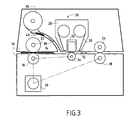
- such a machine comprises a chassis 10 articulated in two parts, an upper part and a lower part, between which is defined a horizontal path 12 for transporting mail items 14.
- a horizontal path 12 for transporting mail items 14 Along this path are at least arranged at the input of the first rolls of transport or drive 16 and at the output of the second rolls of transport or drive 18.
- One or more sets of rollers intermediaries can also be provided on this path between the input and output rollers.
- Each of these rolls is advantageously controlled from a common motor 20.
- these motor rollers are of course associated to madly mounted counter rollers, respectively 22, 24.
- a thermal printing device 26 comprising on the one hand a cassette or removable cartridge 28 containing a thermal transfer ribbon 30 and on the other hand a thermal printing head 32.
- This head comprises conventionally several thermal printing elements arranged in line in a direction transverse to the direction of movement of the articles of mail 14.
- Push means 34 are provided under the print head to contact and ensure sufficient pressure of the ribbon thermal transfer on mail items when printing the postal imprint.
- These thrust means which are controlled in synchronization with printing can consist of a roller printing plate or a printing plate.
- the franking machine can also include a dispenser of labels 36 to allow the franking of packages or articles of mail which because of their thickness could not pass by the way of transport of mail items 12.
- a path 38 of transport of these labels 40 joined this way of transporting mail items to level of the thermal print head 32 upstream thereof.
- the printing process implemented in the franking machine mentioned above uses the technology known as non heat transfer and which consists of depositing by means of a heat source (the head thermal printing 32) of hot-melt ink (present on a outer layer of thermal transfer ribbon 30) on a support synthetic or conventional paper (mail item 14 or label 40 which will then be stuck on the postage package).
- a heat source the head thermal printing 32
- hot-melt ink present on a outer layer of thermal transfer ribbon 30
- a support synthetic or conventional paper email item 14 or label 40 which will then be stuck on the postage package.
- an improved printing method is proposed by what the thermal transfer ribbon (as well as the cassette that incorporates it and all the organs necessary for its training, its guidance, etc.) is purely and simply deleted, the support to be printed being beforehand covered with a heat-sensitive recording material intended to cooperate with the thermal printing head 32 of the franking machine for by heating the postal imprint.
- the impression of this imprint mail is made directly on mail items which can be formed entirely of this heat-sensitive recording material or be simply fitted on a part of them, at the place of printing, of a film of this heat-sensitive recording material reactive to a heat source (see below).
- the heat-sensitive recording material is composed conventionally of a chromogenic substance such as a leuco dye and a chromogenic developer such as a phenolic compound, which react with heat to form a color.
- a chromogenic substance such as a leuco dye
- a chromogenic developer such as a phenolic compound
- French patent application FR 2 575 199 illustrates a coating composition intended to improve resistance to oils, solvents and water from heat-sensitive recording paper. Of even, in the French patent application FR 2 731 181, these are the specific characteristics of the heat-sensitive material which are improved to give it better resistance to UV radiation.
- FIG. 2 shows an exemplary embodiment of an envelope 50 used for implementing the method according to the invention.
- This envelope has an envelope body 52, for example made of paper conventional, on which is pre-deposited during its manufacture (by bonding or any other equivalent process), a longitudinal strip 54 of a length substantially equal to that of the envelope and a width sufficient for printing the postal imprint and possibly a slogan or logo, in the range of 25 to 35 millimeters.
- the band longitudinal comprises the aforementioned heat-sensitive recording material and optionally an additional coating composition such as that described in patent FR 2 575 199.
- the envelope can also be carried out entirely and not only in part from only heat-sensitive recording material and therefore not contain all of conventional paper.
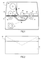
- Figure 1 shows a franking machine implementing the thermal printing process according to the invention. It has a chassis 60 articulated in two parts, an upper part 62 and a lower part 64, between which is defined a horizontal path 66 for transporting the articles of mail 68. Along this path are arranged several series of rollers transport including at least first drive rollers 70 in input and second drive rollers 72 at output. Each of these rollers is advantageously controlled from a common motor 74. To ensure the delivery of mail items, these motor rollers are of course associated with crazy mounted counter rollers, respectively 76, 78.
- a thermal print head 80 conventionally comprising several thermal printing elements arranged in line in a direction transverse to the direction of movement of mail items is arranged on path 66 for transporting mail items.
- Of pressure means 82 are provided under the print head for placing in close contact with thermal printing elements and material thermosensitive recording.
- the franking machine can also include a dispenser of labels 84 powered by labels 86 preferably self-adhesive formed with thermally sensitive recording material.
- a module of wetting / bonding 88 is advantageously provided downstream of the head to allow if necessary to moisten the labels and to press-on bonding (at eg exit rollers 72, 78) directly on the mail items introduced into the machine's entry preferably by a second transport route for these articles 90.
- a coating module 92 can be provided at the exit of the franking machine to add this composition coating on the franked mail item in order to improve in particular its resistance to radiation and scratches.
Abstract
Description
La présente invention se rapporte au domaine des machines à affranchir et plus particulièrement aux machines à affranchir pourvues d'un dispositif d'impression thermique.The present invention relates to the field of machines for franking and more particularly to franking machines provided with a thermal printing device.
Les machines à affranchir des articles de courrier munies d'un dispositif d'impression thermique sont bien connues. La tête d'impression de ces machines comportent classiquement plusieurs éléments d'impression thermique disposés en ligne transversalement à la direction de déplacement des articles de courrier et dont la mise en oeuvre est effectuée par des moyens de commande en fonction d'un cycle de chauffage déterminé selon l'empreinte postale à imprimer. Pour permettre cette impression, un ruban de transfert thermique est interposé entre ces éléments d'impression et l'article de courrier sur lequel l'empreinte postale doit être apposée.Machines for franking articles of mail provided with a thermal printing device are well known. Print head of these machines conventionally comprise several printing elements thermal arranged in line transverse to the direction of movement mail items, the implementation of which is carried out by control means according to a heating cycle determined according to the postal imprint to be printed. To allow this printing, a ribbon of thermal transfer is interposed between these printing elements and the article of mail on which the postal imprint must be affixed.
Le ruban de transfert thermique est monté dans une cartouche consommable qui est débitée au fur et à mesure de l'avancement des articles de courrier, ce qui nécessite le recours à des moyens d'entraínement et des moyens de synchronisation de la rotation du ruban avec l'avancée des articles de courrier. Compte tenu de la valeur monétaire attachée à l'empreinte postale, ces divers moyens doivent être particulièrement fiables.Thermal transfer ribbon is mounted in a cartridge consumable which is debited as the articles progress of mail, which requires the use of means of training and means for synchronizing the rotation of the ribbon with the advance of the mail items. Given the monetary value attached to the postal imprint, these various means must be particularly reliable.
En pratique, l'utilisation de tels rubans entraínent de nombreux inconvénients, notamment au niveau du maintien ou de l'entraínement du ruban, comme l'illustrent par exemple les demandes de brevets européens n°0 494 942, n°0 550 227 et n°0 714 232 déposées au non de la Société Neopost Limited. In practice, the use of such ribbons leads to many disadvantages, especially in terms of maintaining or training the ribbon, as illustrated for example by European patent applications n ° 0 494 942, n ° 0 550 227 and n ° 0 714 232 filed in the name of the Company Neopost Limited.
La présente invention a pour objet de s'affranchir des nombreux problèmes posés par la mise en oeuvre du ruban de transfert thermique dans les machines à affranchir conventionnelles en proposant un procédé d'impression thermique dont la fiabilité est grandement améliorée. Un but de l'invention est de pouvoir mettre en oeuvre ce procédé à partir d'une machine à affranchir traditionnelle. Un autre but de l'invention est en outre d'assurer une qualité d'impression constante dans le temps.The object of the present invention is to overcome the numerous problems posed by the implementation of the thermal transfer ribbon in conventional franking machines by proposing a process thermal printing whose reliability is greatly improved. A goal of the invention is to be able to implement this method from a traditional postage meter. Another object of the invention is further ensure consistent print quality over time.
Ces buts sont atteints par un procédé d'impression thermique d'une empreinte postale sur un article de courrier au moyen d'une machine à affranchir munie d'une tête d'impression thermique, procédé dans lequel on fait tout d'abord passer un support d'enregistrement thermosensible pré-déposé sur au moins une partie déterminée de l'article de courrier à affranchir devant des éléments d'impression thermiques de la tête d'impression thennique, ensuite on met en contact intime le support d'enregistrement avec les éléments d'impression et on commande alors sélectivement le chauffage de ces éléments d'impression thermique pour imprimer l'empreinte postale sur ce support d'enregistrement thermosensible.These objects are achieved by a thermal printing process of a postal imprint on a mail item using a mailing machine franking provided with a thermal printing head, process in which first passes a pre-deposited heat-sensitive recording medium on at least a specific part of the mail item to franking in front of thermal printing elements of the head thermal printing, then we put in intimate contact the support recording with the printing elements and then order selectively heating these thermal printing elements to print the postal imprint on this recording medium thermosensitive.
Avec ce nouveau procédé sans cartouche, tous les problèmes liés à l'utilisation de la cartouche de transfert thermique sont bien évidemment supprimés et la structure de la machine à affranchir correspondante est d'autant simplifiée tout en restant de type conventionnel, notamment au niveau de ses moyens d'impression.With this new cartridge-free process, all the problems related to the use of the thermal transfer cartridge are obviously deleted and the structure of the corresponding franking machine is all the more simplified while remaining conventional, in particular level of its printing resources.
De préférence, afin d'améliorer la résistance aux rayonnements et aux rayures du support d'enregistrement thermosensible, on enduit en outre l'article de courrier affranchi d'une composition d'enduction.Preferably, in order to improve the resistance to radiation and scratches on the heat-sensitive recording medium, it is further coated the mail item freed from a coating composition.
La présente invention concerne également une machine à affranchir comprenant une tête d'impression thermique munie d'une pluralité d'éléments d'impression thermiques pouvant être chauffés sélectivement et des moyens pour presser contre les éléments d'impression un support d'enregistrement thermosensible pré-déposé sur au moins une partie déterminée de l'article de courrier à affranchir, afin d'y imprimer une empreinte postale.The present invention also relates to a franking machine comprising a thermal print head provided with a plurality selectively heatable thermal printing elements and means for pressing a support against the printing elements of heat-sensitive recording pre-deposited on at least part of the mail item to be franked, in order to print a postal imprint.
Il est alors avantageux que la machine à affranchir comporte en outre un module de mouillage/collage pour coller l'étiquette imprimée sur l'article de courrier à affranchir introduit séparément dans la machine à affranchir de préférence par un second chemin de transport des articles de courrier.It is therefore advantageous that the franking machine further comprises a wetting / gluing module to stick the printed label on the postage item to be franked into the mailing machine separately preferably postage by a second transport route for articles of mail.
L'invention se rapporte aussi à tout article de courrier, notamment une enveloppe, muni au moins en partie d'un support d'enregistrement thennosensible et destiné à la mise en oeuvre du procédé d'impression thermique selon l'invention.The invention also relates to any mail item, in particular an envelope, provided at least in part with a recording medium thermosensitive and intended for the implementation of the printing process thermal according to the invention.
D'autres caractéristiques et avantages ressortiront mieux de la description suivante, faite à titre indicatif et non limitatif, en regard des dessins annexés, sur lesquels :
- la figure 1 illustre schématiquement une machine à affranchir selon l'invention,
- la figure 2 représente un exemple de réalisation d'une enveloppe spécialement adaptée pour une utilisation avec la machine de la figure 1, et
- la figure 3 montre de façon schématique une machine à affranchir de l'art antérieur munie d'un dispositif d'impression thermique conventionnel.
- FIG. 1 schematically illustrates a franking machine according to the invention,
- FIG. 2 represents an exemplary embodiment of an envelope specially adapted for use with the machine of FIG. 1, and
- Figure 3 shows schematically a franking machine of the prior art provided with a conventional thermal printing device.
Un exemple d'une machine à affranchir de type connue munie d'un dispositif d'impression thermique conventionnel est illustrée sur la figure 3. An example of a known type of franking machine provided with a conventional thermal printing device is illustrated in Figure 3.
Classiquement, une telle machine comporte un châssis 10 articulé en
deux parties, une partie haute et une partie basse, entre lesquelles est défini
un chemin horizontal 12 de transport des articles de courrier 14. Le long de
ce chemin sont au moins disposés en entrée des premiers rouleaux de
transport ou d'entraínement 16 et en sortie des seconds rouleaux de
transport ou d'entraínement 18. Une ou plusieurs séries de rouleaux
intermédiaires (non représentés) peuvent aussi être prévues sur ce chemin
entre les rouleaux d'entrée et de sortie. Chacun de ces rouleaux est
avantageusement commandé à partir d'un moteur commun 20. Pour assurer
l'acheminement des articles de courrier depuis l'entrée de la machine à
affranchir jusqu'à sa sortie, ces rouleaux moteurs sont bien entendu associés
à des contre-rouleaux montés fous, respectivement 22, 24.Conventionally, such a machine comprises a
Sur le chemin de transport des articles de courrier est disposé un
dispositif d'impression thermique 26 comportant d'une part une cassette ou
cartouche amovible 28 contenant un ruban de transfert thermique 30 et
d'autre part une tête d'impression thermique 32. Cette tête comporte
classiquement plusieurs éléments d'impression thennique disposés en ligne
dans une direction transversale à la direction de déplacement des articles de
courrier 14. Sous la tête d'impression sont prévus des moyens de poussée 34
pour mettre en contact et assurer une pression suffisante du ruban de
transfert thennique sur les articles de courrier lors de l'impression de
l'empreinte postale. Ces moyens de poussée qui sont commandés en
synchronisme avec l'impression peuvent être constitués d'un rouleau
d'impression ou bien d'une plaque d'impression.On the way of transport of the articles of mail is arranged a
De façon classique, différents moyens de commande et de contrôle (non représentés) sont en outre prévus pour assurer entre autres l'entraínement, le maintien sous tension, le guidage, la détection et la commande du ruban de transfert thermique avant, après et pendant l'impression. Conventionally, different means of command and control (not shown) are also provided to ensure inter alia training, maintenance under tension, guidance, detection and order thermal transfer ribbon before, after and during the impression.
La machine à affranchir peut également comporter un distributeur
d'étiquettes 36 pour pennettre l'affranchissement de paquets ou d'articles
de courrier qui du fait de leur épaisseur ne pourraient passer par le chemin
de transport des articles de courrier 12. Un chemin 38 de transport de ces
étiquettes 40 rejoint ce chemin de transport des articles de courrier au
niveau de la tête d'impression thermique 32 en amont de celle-ci.The franking machine can also include a dispenser
of
Le procédé d'impression mis en oeuvre dans la machine à affranchir
précitée utilise la technologie connue sous le non de transfert thermique et
qui consiste à déposer au moyen d'une source de chaleur (la tête
d'impression thermique 32) de l'encre thermofusible (présente sur une
couche externe du ruban de transfert thermique 30) sur un support
synthétique ou papier conventionnel (l'article de courrier 14 ou l'étiquette
40 qui sera ensuite collée sur le paquet à affranchir).The printing process implemented in the franking machine
mentioned above uses the technology known as non heat transfer and
which consists of depositing by means of a heat source (the head
thermal printing 32) of hot-melt ink (present on a
outer layer of thermal transfer ribbon 30) on a support
synthetic or conventional paper (mail item 14 or
Selon l'invention, il est proposé un procédé d'impression amélioré en
ce que le ruban de transfert thennique (ainsi que la cassette qui l'incorpore
et tous les organes nécessaires à son entraínement, son guidage, etc.) est
purement et simplement supprimé, le support à imprimer étant au préalable
recouvert d'un matériau d'enregistrement thermosensible destiné à coopérer
avec la tête d'impression thennique 32 de la machine à affranchir pour
former par chauffage l'empreinte postale. L'impression de cette empreinte
postale est réalisée directement sur les articles de courrier qui peuvent être
formés entièrement de ce matériau d'enregistrement thermosensible ou être
simplement munis sur une partie de ceux-ci, à l'endroit de l'impression,
d'un film de ce matériau d'enregistrement thermosensible réactif à une
source de chaleur (voir ci-après).According to the invention, an improved printing method is proposed by
what the thermal transfer ribbon (as well as the cassette that incorporates it
and all the organs necessary for its training, its guidance, etc.) is
purely and simply deleted, the support to be printed being beforehand
covered with a heat-sensitive recording material intended to cooperate
with the
Le matériau d'enregistrement thermosensible est composé classiquement d'une substance chromogène comme un colorant leuco et d'un développateur chromogène tel qu'un composé phénolique, qui réagissent sous l'effet de la chaleur pour former une couleur. Divers exemples de tels matériaux sont donnés dans la demande EP 0 111 335 au non de la Société Kanzaki Paper Manufacturing Company limited.The heat-sensitive recording material is composed conventionally of a chromogenic substance such as a leuco dye and a chromogenic developer such as a phenolic compound, which react with heat to form a color. Various examples of such materials are given in application EP 0 111 335 to not from Kanzaki Paper Manufacturing Company limited.
Ce matériau est toutefois relativement fragile notamment aux rayures et aux rayonnements. Aussi, il peut être intéressant de le protéger contre ces agressions en le recouvrant par une couche d'enduction destinée à en améliorer la résistance. La demande de brevet Français FR 2 575 199 illustre une composition d'enduction destinée à améliorer la résistance aux huiles, solvants et à l'eau d'un papier d'enregistrement thermosensible. De même, dans la demande de brevet Français FR 2 731 181, ce sont les caractéristiques propres du matériau thermosensible qui sont améliorées pour lui assurer une meilleure résistance aux rayonnements UV.However, this material is relatively fragile, in particular from scratches and radiation. Also, it may be worth protecting it against these attacks by covering it with a coating intended to improve resistance. French patent application FR 2 575 199 illustrates a coating composition intended to improve resistance to oils, solvents and water from heat-sensitive recording paper. Of even, in the French patent application FR 2 731 181, these are the specific characteristics of the heat-sensitive material which are improved to give it better resistance to UV radiation.
La figure 2 montre un exemple de réalisation d'une enveloppe 50
utilisée pour la mise en oeuvre du procédé selon l'invention. Cette
enveloppe comporte un corps d'enveloppe 52, par exemple en papier
conventionnel, sur laquelle est pré-déposée lors de sa fabrication (par
collage ou tout autre procédé équivalent), une bande longitudinale 54 d'une
longueur sensiblement égale à celle de l'enveloppe et d'une largeur
suffisante pour l'impression de l'empreinte postale et éventuellement d'un
slogan ou d'un logo, soit de l'ordre de 25 à 35 millimètres. La bande
longitudinale comporte le matériau d'enregistrement thermosensible précité
et éventuellement une composition supplémentaire d'enduction telle que
celle décrite dans le brevet FR 2 575 199. Bien entendu, l'enveloppe peut
également être réalisée entièrement et non seulement en partie à partir du
seul matériau d'enregistrement thermosensible et donc ne pas comporter du
tout de papier conventionnel.FIG. 2 shows an exemplary embodiment of an
La figure 1 montre une machine à affranchir mettant en oeuvre le
procédé d'impression thermique selon l'invention. Elle comporte un châssis
60 articulé en deux parties, une partie haute 62 et une partie basse 64, entre
lesquelles est défini un chemin horizontal 66 de transport des articles de
courrier 68. Le long de ce chemin sont disposés plusieurs séries de rouleaux
de transport dont au moins des premiers rouleaux d'entraínement 70 en
entrée et des seconds rouleaux d'entraínement 72 en sortie. Chacun de ces
rouleaux est avantageusement commandé à partir d'un moteur commun 74.
Pour assurer l'acheminement des articles de courrier, ces rouleaux moteurs
sont bien entendu associés à des contre-rouleaux montés fous,
respectivement 76, 78.Figure 1 shows a franking machine implementing the
thermal printing process according to the invention. It has a
Une tête d'impression thennique 80 comportant classiquement
plusieurs éléments d'impression thermique disposés en ligne dans une
direction transversale à la direction de déplacement des articles de courrier
est disposée sur le chemin 66 de transport des articles de courrier. Des
moyens de pression 82 sont prévus sous la tête d'impression pour une mise
en contact intime des éléments d'impression thermique et du matériau
d'enregistrement thermosensible.A
La machine à affranchir peut comporter également un distributeur
d'étiquettes 84 alimenté par des étiquettes 86 de préférence auto-adhésives
formées avec le matériau d'enregistrement thennosensible. Un module de
mouillage/collage 88 est avantageusement prévu en aval de la tête
d'impression pour permettre si nécessaire d'humecter les étiquettes et de les
coller par pression (au niveau par exemple des rouleaux de sortie 72, 78)
directement sur les articles de courrier introduits en entrée de la machine de
préférence par un second chemin de transport de ces articles 90.The franking machine can also include a dispenser
of
De même. lorsque l'enveloppe n'a pas été préalablement enduite
d'une composition d'enduction, un module d'enduction 92 peut être prévu
en sortie de la machine à affranchir pour adjoindre cette composition
d'enduction sur l'article de courrier affranchi afin d'améliorer notamment
sa résistance aux rayonnements et aux rayures.Likewise. when the envelope has not been previously coated
of a coating composition, a
Ainsi, avec la présente invention, quasiment sans changer la structure globale d'une machine à affranchir conventionnelle du type à impression thermique (le dispositif de transport des articles de courrier et les moyens d'impression restent les mêmes), il est possible de mettre en oeuvre un nouveau procédé d'impression thermique qui s'affranchisse totalement des problèmes nombreux et particulièrement sensibles posés par la présence de la cartouche amovible de ruban de transfert thermique que comporte nécessairement une telle machine conventionnelle.Thus, with the present invention, almost without changing the structure overview of a conventional franking machine of the printing type thermal (the device for transporting mail items and the means remain the same), it is possible to use a new thermal printing process which completely overcomes numerous and particularly sensitive problems posed by the presence of the removable thermal transfer ribbon cartridge necessarily such a conventional machine.
Claims (5)
Applications Claiming Priority (2)
| Application Number | Priority Date | Filing Date | Title |
|---|---|---|---|
| FR9810901 | 1998-09-01 | ||
| FR9810901A FR2782823B1 (en) | 1998-09-01 | 1998-09-01 | THERMAL PRINTING PROCESS |
Publications (2)
| Publication Number | Publication Date |
|---|---|
| EP0984399A1 true EP0984399A1 (en) | 2000-03-08 |
| EP0984399B1 EP0984399B1 (en) | 2003-01-15 |
Family
ID=9530011
Family Applications (1)
| Application Number | Title | Priority Date | Filing Date |
|---|---|---|---|
| EP19990402146 Expired - Lifetime EP0984399B1 (en) | 1998-09-01 | 1999-08-30 | Method for thermal printing |
Country Status (3)
| Country | Link |
|---|---|
| EP (1) | EP0984399B1 (en) |
| DE (1) | DE69904896T2 (en) |
| FR (1) | FR2782823B1 (en) |
Cited By (2)
| Publication number | Priority date | Publication date | Assignee | Title |
|---|---|---|---|---|
| FR2829269A1 (en) * | 2001-08-31 | 2003-03-07 | Neopost Ind | Modular franking system for postal items has a radio-linked computer for controlling franking |
| WO2003064159A1 (en) * | 2002-01-31 | 2003-08-07 | Neopost Limited | Item printing system |
Citations (10)
| Publication number | Priority date | Publication date | Assignee | Title |
|---|---|---|---|---|
| EP0111335A2 (en) | 1982-12-11 | 1984-06-20 | Kanzaki Paper Manufacturing Company Limited | Heat-sensitive recording material |
| EP0165601A2 (en) * | 1984-06-19 | 1985-12-27 | Pitney Bowes Inc. | Thermal printer and postal meter having thermal printer |
| FR2575199A1 (en) | 1984-12-21 | 1986-06-27 | Nippon Synthetic Chem Ind | COATING COMPOSITION FOR USEFUL PAPER, IN PARTICULAR AS A PROTECTIVE LAYER FOR THERMAL RECORDING PAPER |
| US4705417A (en) * | 1985-01-19 | 1987-11-10 | Pa Consulting Services Limited | Postal franking machine |
| US4739343A (en) * | 1986-05-09 | 1988-04-19 | Pitney Bowes Inc. | Thermal printing system for postage meter mailing machine application |
| EP0494942A1 (en) | 1989-10-02 | 1992-07-22 | Astra Ab | Process for the manufacture of budesonide. |
| EP0550227A2 (en) | 1991-12-30 | 1993-07-07 | Neopost Limited | Multi-strike ink ribbon feed control |
| EP0709215A2 (en) * | 1994-10-28 | 1996-05-01 | Pitney Bowes Inc. | Thermal printer |
| EP0714232A1 (en) | 1994-06-17 | 1996-06-05 | Maasland N.V. | An implement for automatically milking animals |
| FR2731181A1 (en) | 1995-02-16 | 1996-09-06 | Ricoh Kk | Recording material |
-
1998
- 1998-09-01 FR FR9810901A patent/FR2782823B1/en not_active Expired - Fee Related
-
1999
- 1999-08-30 EP EP19990402146 patent/EP0984399B1/en not_active Expired - Lifetime
- 1999-08-30 DE DE1999604896 patent/DE69904896T2/en not_active Expired - Lifetime
Patent Citations (10)
| Publication number | Priority date | Publication date | Assignee | Title |
|---|---|---|---|---|
| EP0111335A2 (en) | 1982-12-11 | 1984-06-20 | Kanzaki Paper Manufacturing Company Limited | Heat-sensitive recording material |
| EP0165601A2 (en) * | 1984-06-19 | 1985-12-27 | Pitney Bowes Inc. | Thermal printer and postal meter having thermal printer |
| FR2575199A1 (en) | 1984-12-21 | 1986-06-27 | Nippon Synthetic Chem Ind | COATING COMPOSITION FOR USEFUL PAPER, IN PARTICULAR AS A PROTECTIVE LAYER FOR THERMAL RECORDING PAPER |
| US4705417A (en) * | 1985-01-19 | 1987-11-10 | Pa Consulting Services Limited | Postal franking machine |
| US4739343A (en) * | 1986-05-09 | 1988-04-19 | Pitney Bowes Inc. | Thermal printing system for postage meter mailing machine application |
| EP0494942A1 (en) | 1989-10-02 | 1992-07-22 | Astra Ab | Process for the manufacture of budesonide. |
| EP0550227A2 (en) | 1991-12-30 | 1993-07-07 | Neopost Limited | Multi-strike ink ribbon feed control |
| EP0714232A1 (en) | 1994-06-17 | 1996-06-05 | Maasland N.V. | An implement for automatically milking animals |
| EP0709215A2 (en) * | 1994-10-28 | 1996-05-01 | Pitney Bowes Inc. | Thermal printer |
| FR2731181A1 (en) | 1995-02-16 | 1996-09-06 | Ricoh Kk | Recording material |
Cited By (3)
| Publication number | Priority date | Publication date | Assignee | Title |
|---|---|---|---|---|
| FR2829269A1 (en) * | 2001-08-31 | 2003-03-07 | Neopost Ind | Modular franking system for postal items has a radio-linked computer for controlling franking |
| EP1293936A1 (en) * | 2001-08-31 | 2003-03-19 | Neopost Industrie | Modular and universal system for treating mail |
| WO2003064159A1 (en) * | 2002-01-31 | 2003-08-07 | Neopost Limited | Item printing system |
Also Published As
| Publication number | Publication date |
|---|---|
| DE69904896D1 (en) | 2003-02-20 |
| DE69904896T2 (en) | 2003-11-13 |
| EP0984399B1 (en) | 2003-01-15 |
| FR2782823B1 (en) | 2000-11-17 |
| FR2782823A1 (en) | 2000-03-03 |
Similar Documents
| Publication | Publication Date | Title |
|---|---|---|
| FR2754761A1 (en) | Method of activating heat sensitive label | |
| US4707211A (en) | Linerless thermal label printer and applicator | |
| US4784714A (en) | Linerless thermal label printer and applicator | |
| FR2475495A1 (en) | APPARATUS FOR CONTROLLING PRINTING LABELS, LABELS AND METHOD FOR CONTROLLING SUCH APPARATUS | |
| EP0993963B1 (en) | Plastic film continuous printing process, apparatus therefore and plastic film printed by the same | |
| EP0637547B1 (en) | Printing system for labels | |
| EP0965446B1 (en) | Security printing machine for printing security paper | |
| FR2555548A1 (en) | APPARATUS AND METHOD FOR WINDING A PLASTIC LABEL AROUND A CONTAINER | |
| CH657020A5 (en) | METHOD OF MARKING THE OUTER SHELL OF SMOKING ARTICLES. | |
| FR2612879A1 (en) | APPARATUS FOR SUPPLYING A MATERIAL IN THE FORM OF A FILM | |
| FR2773107A1 (en) | REVERSIBLE THERMAL RECORDING METHOD AND APPARATUS | |
| FR2589611A1 (en) | ROLL FOR APPLYING A SOLVENT ON PLASTIC LABELS | |
| EP0984399B1 (en) | Method for thermal printing | |
| FR2589431A1 (en) | Method and appliance for applying a plastic label around a container | |
| EP1193655B1 (en) | Multi-purpose franking machine | |
| CA2494409A1 (en) | System for stamping mail by means of secure external printing | |
| FR2479775A1 (en) | Labelling machine for printed labels - has labels supplied in striP with backing paper pulled off strip before application by roller | |
| CH677340A5 (en) | ||
| FR2459520A1 (en) | Laminated labels for cosmetic packs - made from matched films and cut prior to cooling to minimise distortion and delamination | |
| EP0201440B1 (en) | Marking of a piece of cloth, device for carrying out this method and label obtained | |
| JP2550736Y2 (en) | Thermal labeler | |
| CH679141A5 (en) | ||
| EP0787594A1 (en) | Ink ribbon recharging for a thermal transfer printer | |
| JPH08122981A (en) | Photographic sensitive material package and packing device | |
| JP3619590B2 (en) | Single-leaf label transfer device |
Legal Events
| Date | Code | Title | Description |
|---|---|---|---|
| PUAI | Public reference made under article 153(3) epc to a published international application that has entered the european phase |
Free format text: ORIGINAL CODE: 0009012 |
|
| AK | Designated contracting states |
Kind code of ref document: A1 Designated state(s): AT BE CH CY DE DK ES FI FR GB GR IE IT LI LU MC NL PT SE |
|
| AX | Request for extension of the european patent |
Free format text: AL;LT;LV;MK;RO;SI |
|
| 17P | Request for examination filed |
Effective date: 20000809 |
|
| AKX | Designation fees paid |
Free format text: DE FR GB |
|
| 17Q | First examination report despatched |
Effective date: 20011127 |
|
| GRAH | Despatch of communication of intention to grant a patent |
Free format text: ORIGINAL CODE: EPIDOS IGRA |
|
| GRAH | Despatch of communication of intention to grant a patent |
Free format text: ORIGINAL CODE: EPIDOS IGRA |
|
| GRAA | (expected) grant |
Free format text: ORIGINAL CODE: 0009210 |
|
| AK | Designated contracting states |
Kind code of ref document: B1 Designated state(s): DE FR GB |
|
| REG | Reference to a national code |
Ref country code: GB Ref legal event code: FG4D Free format text: NOT ENGLISH |
|
| REF | Corresponds to: |
Ref document number: 69904896 Country of ref document: DE Date of ref document: 20030220 Kind code of ref document: P |
|
| GBT | Gb: translation of ep patent filed (gb section 77(6)(a)/1977) |
Effective date: 20030513 |
|
| PLBE | No opposition filed within time limit |
Free format text: ORIGINAL CODE: 0009261 |
|
| STAA | Information on the status of an ep patent application or granted ep patent |
Free format text: STATUS: NO OPPOSITION FILED WITHIN TIME LIMIT |
|
| 26N | No opposition filed |
Effective date: 20031016 |
|
| PGFP | Annual fee paid to national office [announced via postgrant information from national office to epo] |
Ref country code: GB Payment date: 20090827 Year of fee payment: 11 Ref country code: DE Payment date: 20090821 Year of fee payment: 11 |
|
| GBPC | Gb: european patent ceased through non-payment of renewal fee |
Effective date: 20100830 |
|
| REG | Reference to a national code |
Ref country code: FR Ref legal event code: ST Effective date: 20110502 |
|
| REG | Reference to a national code |
Ref country code: DE Ref legal event code: R119 Ref document number: 69904896 Country of ref document: DE Effective date: 20110301 |
|
| PG25 | Lapsed in a contracting state [announced via postgrant information from national office to epo] |
Ref country code: FR Free format text: LAPSE BECAUSE OF NON-PAYMENT OF DUE FEES Effective date: 20100831 Ref country code: DE Free format text: LAPSE BECAUSE OF NON-PAYMENT OF DUE FEES Effective date: 20110301 |
|
| PG25 | Lapsed in a contracting state [announced via postgrant information from national office to epo] |
Ref country code: GB Free format text: LAPSE BECAUSE OF NON-PAYMENT OF DUE FEES Effective date: 20100830 |
|
| PGFP | Annual fee paid to national office [announced via postgrant information from national office to epo] |
Ref country code: FR Payment date: 20090914 Year of fee payment: 11 |