EP0984097A2 - Apparatus for processing permeable or semi-permeable webs - Google Patents
Apparatus for processing permeable or semi-permeable webs Download PDFInfo
- Publication number
- EP0984097A2 EP0984097A2 EP98309055A EP98309055A EP0984097A2 EP 0984097 A2 EP0984097 A2 EP 0984097A2 EP 98309055 A EP98309055 A EP 98309055A EP 98309055 A EP98309055 A EP 98309055A EP 0984097 A2 EP0984097 A2 EP 0984097A2
- Authority
- EP
- European Patent Office
- Prior art keywords
- drying cylinder
- air
- cylinder
- drying
- conduits
- Prior art date
- Legal status (The legal status is an assumption and is not a legal conclusion. Google has not performed a legal analysis and makes no representation as to the accuracy of the status listed.)
- Granted
Links
Images


Classifications
-
- F—MECHANICAL ENGINEERING; LIGHTING; HEATING; WEAPONS; BLASTING
- F26—DRYING
- F26B—DRYING SOLID MATERIALS OR OBJECTS BY REMOVING LIQUID THEREFROM
- F26B13/00—Machines and apparatus for drying fabrics, fibres, yarns, or other materials in long lengths, with progressive movement
- F26B13/10—Arrangements for feeding, heating or supporting materials; Controlling movement, tension or position of materials
- F26B13/14—Rollers, drums, cylinders; Arrangement of drives, supports, bearings, cleaning
- F26B13/16—Rollers, drums, cylinders; Arrangement of drives, supports, bearings, cleaning perforated in combination with hot air blowing or suction devices, e.g. sieve drum dryers
-
- D—TEXTILES; PAPER
- D21—PAPER-MAKING; PRODUCTION OF CELLULOSE
- D21F—PAPER-MAKING MACHINES; METHODS OF PRODUCING PAPER THEREON
- D21F5/00—Dryer section of machines for making continuous webs of paper
- D21F5/18—Drying webs by hot air
- D21F5/182—Drying webs by hot air through perforated cylinders
Definitions
- This invention relates to an air processing apparatus for drying, curing, thermal bonding, cooling, and web transferring permeable or semi-permeable webs such as fabrics, paper, or the like.
- Typical of such an apparatus is the honeycomb system described in U.S. Patent No. 4,542,596.
- a non-rotating structure within the roll provides multiple zones for web processing and a vacuum is applied to a plurality of honeycomb grilled conduits so that the web can be dried uniformly and without the 'blind spots' which characterize other devices.
- this patented system is flow limited due to the vacuum source and, also, it is limited because air flow through the conduits is not distributed evenly.
- the incorporation of multiple vacuum means within the roll so as to create different zones of air flow on the drying cylinder is difficult to achieve because of the limited space within the cylinder.
- the present invention is an improvement over this and other known devices because it allows multiple zones to be created within a cylinder without an internal non-rotating structure; moreover, it allows air to flow equally through the inlet and outlet holes of the conduits so that a web can be dried evenly.
- the present invention makes it possible to isolate and direct air flow into a greater number of separate zones on a single cylinder so that the process air of one zone cannot mix with the process air of another zone.
- This distribution tube is fixed within the cylinder but it is distinguishable from the non-rotating structure of U.S. Patent No. 4,542,596 because it revolves as the cylinder revolves and, therefore, is not stationary.
- the air which is impelled by the distribution tube within the cylinder ultimately escapes through the outer porous shell through a multiplicity of air zones, a feature which distinguishes this invention from those devices which exhaust the process air from the drying roll in an axial manner.
- Typical applications include, for example, drying, cooling, and thermal bonding paper, fabrics, webs, and other sheet-like material.
- Another object is to provide a novel cylinder which because of its high open area lends itself to the tensioning of impermeable products.
- the roll of this invention provides for exhausting air out of one axial area only, or it may contain several axial areas, each having various air flow characteristics, and each of which may be exhausted simultaneously or preferentially, depending on the material which is to be treated.
- Air is exhausted from the roll through the outer surface of the shell, a feature which makes it possible to enhance and control air flow by varying the shell length, something that is not possible with rolls that exhaust air through their axial ends only.
- the object is to use the surface of the cylinder for both air supply and air exhaust.
- the present invention overcomes this drawback in energy consumption and achieves significant economies by neither limiting nor directing the air exhaust exclusively to the cylinder's roll ends. Instead, the exhaust air is impelled and directed through the shell of the cylinder, and the exhaust area can be expanded for any roll size merely by extending the width of the roll so as to keep exhaust velocities low and minimize energy consumption.
- the structure of the present roll makes it useful in high-flow applications because the exhaust air flow area can be increased by simply extending the outside length of the shell to any desired degree.
- the roll of this invention consists of an outer shell and, beneath the shell exterior, one or more channels equipped with distribution means for profiling the flow of air. The ends of the roll are capped.
- the shell may be comprised of any porous material.
- any porous material For example, when high-flow applications are needed, highly porous shells having a high open area in excess of 50% are desirable.
- Typical shells include, for example, honeycomb type shells or square grids fabricated from thin material as, for example, material measuring 0.2 to 4 mm in thickness.
- the shell is covered with a wire screen that bridges the grid and supports the product which is to be dried.
- axial dividers extend radially and intersect an inner cylinder to form channels. And within each channel there is contained a perforated plate that serves as a distribution means for profiling the flow of air. Although the normal object of this plate is to uniformly distribute air flow in the axial direction, it can also be used to vary the flow profiles.
- the roll can be divided into a high flow zone for web transfer onto the roll followed by a zone where hot air is supplied for drying and, also, a zone where there is no air flow so that the product can be easily transferred off the roll.
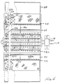
- Figure 1 shows a web 20 being fed onto the drying cylinder of this invention by conventional guideroll means (not shown).
- the drying cylinder 12 ( Figures 1 and 2) consists essentially of a cylindrical hub 14 mounted on an axle 19 which is rotatably mounted in a pair of bearings 18.
- the cylinder 12 includes a plurality of axially extending conduits 22 arranged together in cylindrical configuration. These conduits 22 are formed by a plurality of radial plates 24 ( Figure 2) extending along the longitudinal axis of the drying cylinder 12. Plates 24 extend outward radially from hub 14 to the periphery of cylinder 12.
- Each of the conduits 22 has their radial plates 24 converging toward each other so as to form a generally inwardly tapered channel 15 where they intersect the cylindrical hub 14 ( Figure 3).
- the conduits 22 are covered by a cylindrical shell 41 ( Figure 3) comprised of a screen 44 and a cylindrical underframe or support structure 46.
- This support structure 46 may be in the form of a perforated plate equipped with a reticulated pattern of holes which are shown as inlet ports 48a and outlet ports 48b in Figures 1 and 4 or it may take the form of a honeycomb-type shell or grid-type structure.
- the support structure 46 and radial plates 24 are fabricated from steel or other suitably rigid material and the screen 44 is steel wire mesh or an interwoven fabric.
- the support structure 46 generally has an open surface area which is capable of accommodating a wide range of applications. Typical of these are operations in which the open areas are in excess of 50%, in which case the inlet ports 48a and outlet ports 48b cover a combined area of more than one-half the total surface; however, this process is not limited to rolls with large open areas only, and it is to be understood that smaller open areas as, for example, those of less than 50%, are also within the scope of this invention. If the support structure 46 is a perforated plate, its radial thickness may be in the range of from about 0.2 to 4 mm; however, if a honeycomb or grid-type structure is employed then their respective radial thicknesses will be appreciably greater and may be in the range of from about 25-200 mm.
- the support structure 46 is covered by a screen 44 that supports the web 20.
- the axially extending conduits 22 are sealed at their ends by circular end portions 34 as shown in Figures 4 and 5 or each respective end may be sealed individually.
- a vertically disposed divider air dam 36 which is parallel to the end portions 34, extends partially through the drying cylinder 12 and divides each conduit 22 longitudinally into a front chamber 50 having inlet ports 48a and a rear chamber 52 having outlet ports 48b.
- the air dam 26 extends circumferentially around the drying cylinder 12 as shown in Figure 5.
- An inner cylindrical axial air distributor 26, constructed and arranged to be concentric with the longitudinal axis of the cylindrical hub 14, divides each of the conduits radially into an outer chamber 28 and inner chamber 30 ( Figures 2 and 3).
- the inner cylindrical axial air distributor 26 is perforated with flow port means in the form of apertures 32a and 32b ( Figure 4) which provide for air flow between said inner chamber 30 and outer chamber 28.
- the apertures become progressively smaller as they near the air dam 36 and larger as they approach the end portions 34. This has the effect of evenly distributing air flow; however, other means of evenly distributing air flow as, for example, by the use of a longitudinally extended graduated slot may also be employed.
- the apertures in the air distributor may be sized to any desired dimension so as to achieve any desired air flow profile or, alternatively, the position of the radial plates 24 may be varied to obtain the desired flow profile.
- drying cylinder 12 The exterior of drying cylinder 12 is partially enclosed by a housing 38.
- a pair of axial seals 40 extend along the longitudinal axis of the cylindrical hub 14 and seal the drying cylinder 12 against the housing 38 as shown in Figure 2.
- the seals 40 extend axially across the width of the conduit 22 so as to eliminate any gap between the seal and the radial plate and thus avoid or minimize air leakage.
- the web 20 can be removed at the sector S where the web 20 is not enclosed by the housing 38 since there is no air flow in that zone.
- the housing 38 includes a front intake duct 54 ( Figure 6), arranged to supply air to the inlet ports 48a, and a rear exhaust duct 56.
- a circumferential air seal 53 ( Figures 1 and 5) is positioned between the intake and exhaust ducts to prevent air leakage therebetween. In embodiments where a plurality of intake and/or exhaust ducts are used (discussed below), it should be understood that seals would be disposed between these intake/exhaust ducts as well.
- a second circumferential air seal 55 ( Figure 4) is secured to the outboard edge of the housing 38 to prevent leakage of air from housing 38. Still another seal 55 is fitted onto the outboard edge of the exhaust duct 56 to avoid having outside air leak into the system.
- the air flow illustrated by the arrows in Figures 1, 2, 3, 6, and 7 is produced by a vacuum source (42, 42a, and 42b) located at the exhaust opening 61 ( Figures 1 and 6), which draws air into the inlet ports 48a and through the apertures 32a of the air distributor 26. The air then flows longitudinally through the conduits 22 under the air dam 36 to the rear chamber 52 ( Figure 4). The air is then drawn through the apertures 32a of the air distributor 26 and expelled through the outlet ports 48b to the exhaust duct 56; however, it should be noted that other means for channeling air through the conduit as, for example, by the use of blower means may also be employed.
- the drying cylinder includes two areas or zones of desired air flow.
- an upper intake and exhaust duct network 60 combines with vacuum source 42a to form a first zone 66 and a lower intake and exhaust duct network 62 combines with vacuum source 42b to form a second zone 68.
- the lower intake duct can be removed as shown in Figure 6, or multiple intake and exhaust duct networks for multiple zones can be employed.
- this system is not flow limited and, in fact, air flow can be enhanced and controlled by extending the width of the shell. This is a significant advantage over rolls that exhaust air out the axial ends only.
- this drying cylinder is comprised of plates that penetrate radially into the cylinder and form conduits which intersect an inner cylindrical hub 14.
- the conduits are further divided axially to create within the cylinder multiple zones which produce various air flow characteristics on the outer surface of the drying cylinder.
- the inlet and outlet holes of the air distributor 26 are sized to permit the air to flow evenly or create a desired profile.
- a honeycomb type shell may be used, it is not essential and other types of shells may also be employed.
Abstract
Description
- This invention relates to an air processing apparatus for drying, curing, thermal bonding, cooling, and web transferring permeable or semi-permeable webs such as fabrics, paper, or the like.
- Typical of such an apparatus is the honeycomb system described in U.S. Patent No. 4,542,596. In this system, a non-rotating structure within the roll provides multiple zones for web processing and a vacuum is applied to a plurality of honeycomb grilled conduits so that the web can be dried uniformly and without the 'blind spots' which characterize other devices. Unfortunately however, this patented system is flow limited due to the vacuum source and, also, it is limited because air flow through the conduits is not distributed evenly. Moreover, the incorporation of multiple vacuum means within the roll so as to create different zones of air flow on the drying cylinder is difficult to achieve because of the limited space within the cylinder.
- The present invention is an improvement over this and other known devices because it allows multiple zones to be created within a cylinder without an internal non-rotating structure; moreover, it allows air to flow equally through the inlet and outlet holes of the conduits so that a web can be dried evenly.
- As a result, the present invention makes it possible to isolate and direct air flow into a greater number of separate zones on a single cylinder so that the process air of one zone cannot mix with the process air of another zone.
- This ability to selectively isolate and direct air flow into a multiplicity of zones is a feature not shared by the apparatus covered in U.S. Patent No. 4,542,596 so that now, for the first time, it is possible to obtain economies in energy and other advantages such as isolating contaminants which, heretofore, were impossible to achieve.
- These advantages are obtained by incorporating within each cylinder a stationary air distribution tube which distributes process air uniformly throughout the cylinder in an axial direction.
- This distribution tube is fixed within the cylinder but it is distinguishable from the non-rotating structure of U.S. Patent No. 4,542,596 because it revolves as the cylinder revolves and, therefore, is not stationary.
- The air which is impelled by the distribution tube within the cylinder ultimately escapes through the outer porous shell through a multiplicity of air zones, a feature which distinguishes this invention from those devices which exhaust the process air from the drying roll in an axial manner.
- It is an object of this invention to provide a novel roll for the through-air processing of permeable and semi-permeable webs. Typical applications include, for example, drying, cooling, and thermal bonding paper, fabrics, webs, and other sheet-like material.
- Another object is to provide a novel cylinder which because of its high open area lends itself to the tensioning of impermeable products.
- The roll of this invention provides for exhausting air out of one axial area only, or it may contain several axial areas, each having various air flow characteristics, and each of which may be exhausted simultaneously or preferentially, depending on the material which is to be treated.
- Air is exhausted from the roll through the outer surface of the shell, a feature which makes it possible to enhance and control air flow by varying the shell length, something that is not possible with rolls that exhaust air through their axial ends only.
- In the present invention, the object is to use the surface of the cylinder for both air supply and air exhaust.
- By comparison, known devices, specifically those which exhaust air from a cylinder's axial ends in high flow applications, reach air velocities that are so high as to make energy consumption excessive.
- The present invention overcomes this drawback in energy consumption and achieves significant economies by neither limiting nor directing the air exhaust exclusively to the cylinder's roll ends. Instead, the exhaust air is impelled and directed through the shell of the cylinder, and the exhaust area can be expanded for any roll size merely by extending the width of the roll so as to keep exhaust velocities low and minimize energy consumption.
- Since air is forced out of the cylinder surface, the area available for exhausting air is virtually unlimited and it can be increased by merely increasing the length of the cylinder. This exhaustability has significant process advantages over devices which employ cylinders whose exhaust area is confined to the cylinders axial ends.
- Accordingly, the structure of the present roll makes it useful in high-flow applications because the exhaust air flow area can be increased by simply extending the outside length of the shell to any desired degree.
- Structurally, the roll of this invention consists of an outer shell and, beneath the shell exterior, one or more channels equipped with distribution means for profiling the flow of air. The ends of the roll are capped.
- The shell may be comprised of any porous material. For example, when high-flow applications are needed, highly porous shells having a high open area in excess of 50% are desirable.
- Typical shells include, for example, honeycomb type shells or square grids fabricated from thin material as, for example, material measuring 0.2 to 4 mm in thickness. When a high-open-area type shell construction is used, the shell is covered with a wire screen that bridges the grid and supports the product which is to be dried.
- Within each roll, beneath the outer surface of the shell, axial dividers extend radially and intersect an inner cylinder to form channels. And within each channel there is contained a perforated plate that serves as a distribution means for profiling the flow of air. Although the normal object of this plate is to uniformly distribute air flow in the axial direction, it can also be used to vary the flow profiles.
- These channels limit the air flow to the radial and axial directions only and, thus, make it possible to divide the roll into numerous circumferential zones which may be processed independently.
- Thus, for example, the roll can be divided into a high flow zone for web transfer onto the roll followed by a zone where hot air is supplied for drying and, also, a zone where there is no air flow so that the product can be easily transferred off the roll.
- This ability to divide the roll both circumferentially and axially makes it possible to achieve a checkerboard of processing zones so that several operations can be independently achieved on the same roll.
- The following is a description of specific embodiments of invention reference being made to the accompanying drawings in which:
- Figure 1 is an elevational view with portions cut away to illustrate the elements of the drying cylinder.
- Figure 2 is an elevational view of the drying cylinder for use in the air processing of a paper web or the like made up of a plurality of axially extended grilled segments.
- Figure 3 is an enlarged fragmentary elevational view of that section of the drying cylinder which is contained within the phantom lines shown in Figure 2.
- Figure 4 is a sectional view taken along line 4-4 of Figure 2 with portions cut-away.
- Figure 5 is a sectional view taken along line 5-5 of Figure 2.
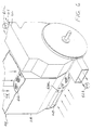
- Figure 6 is a perspective view of another embodiment of the drying cylinder which is shown within a housing equipped with an air intake duct and showing sections cut away to illustrate air flow.
- Figure 7 is a perspective view of an alternative design showing a drying cylinder equipped with a second air intake duct, also with portions cut away to illustrate air flow.
-
- The use of this apparatus in drying permeable and semi-permeable webs is best illustrated by Figure 1 which shows a
web 20 being fed onto the drying cylinder of this invention by conventional guideroll means (not shown). - The drying cylinder 12 (Figures 1 and 2) consists essentially of a
cylindrical hub 14 mounted on anaxle 19 which is rotatably mounted in a pair ofbearings 18. Thecylinder 12 includes a plurality of axially extendingconduits 22 arranged together in cylindrical configuration. Theseconduits 22 are formed by a plurality of radial plates 24 (Figure 2) extending along the longitudinal axis of the dryingcylinder 12. Plates 24 extend outward radially fromhub 14 to the periphery ofcylinder 12. Each of theconduits 22 has their radial plates 24 converging toward each other so as to form a generally inwardlytapered channel 15 where they intersect the cylindrical hub 14 (Figure 3). - The
conduits 22 are covered by a cylindrical shell 41 (Figure 3) comprised of ascreen 44 and a cylindrical underframe orsupport structure 46. Thissupport structure 46 may be in the form of a perforated plate equipped with a reticulated pattern of holes which are shown asinlet ports 48a and outlet ports 48b in Figures 1 and 4 or it may take the form of a honeycomb-type shell or grid-type structure. In either case, thesupport structure 46 and radial plates 24 are fabricated from steel or other suitably rigid material and thescreen 44 is steel wire mesh or an interwoven fabric. - The
support structure 46 generally has an open surface area which is capable of accommodating a wide range of applications. Typical of these are operations in which the open areas are in excess of 50%, in which case theinlet ports 48a and outlet ports 48b cover a combined area of more than one-half the total surface; however, this process is not limited to rolls with large open areas only, and it is to be understood that smaller open areas as, for example, those of less than 50%, are also within the scope of this invention. If thesupport structure 46 is a perforated plate, its radial thickness may be in the range of from about 0.2 to 4 mm; however, if a honeycomb or grid-type structure is employed then their respective radial thicknesses will be appreciably greater and may be in the range of from about 25-200 mm. Thesupport structure 46 is covered by ascreen 44 that supports theweb 20. The axially extendingconduits 22 are sealed at their ends bycircular end portions 34 as shown in Figures 4 and 5 or each respective end may be sealed individually. - A vertically disposed
divider air dam 36, which is parallel to theend portions 34, extends partially through the dryingcylinder 12 and divides eachconduit 22 longitudinally into afront chamber 50 havinginlet ports 48a and a rear chamber 52 having outlet ports 48b. Theair dam 26 extends circumferentially around the dryingcylinder 12 as shown in Figure 5. - An inner cylindrical
axial air distributor 26, constructed and arranged to be concentric with the longitudinal axis of thecylindrical hub 14, divides each of the conduits radially into anouter chamber 28 and inner chamber 30 (Figures 2 and 3). The inner cylindricalaxial air distributor 26 is perforated with flow port means in the form of apertures 32a and 32b (Figure 4) which provide for air flow between saidinner chamber 30 andouter chamber 28. As seen in Figures 1 and 4, the apertures become progressively smaller as they near theair dam 36 and larger as they approach theend portions 34. This has the effect of evenly distributing air flow; however, other means of evenly distributing air flow as, for example, by the use of a longitudinally extended graduated slot may also be employed. Moreover, it should be noted that the apertures in the air distributor may be sized to any desired dimension so as to achieve any desired air flow profile or, alternatively, the position of the radial plates 24 may be varied to obtain the desired flow profile. - The exterior of drying
cylinder 12 is partially enclosed by ahousing 38. A pair ofaxial seals 40 extend along the longitudinal axis of thecylindrical hub 14 and seal thedrying cylinder 12 against thehousing 38 as shown in Figure 2. Theseals 40 extend axially across the width of theconduit 22 so as to eliminate any gap between the seal and the radial plate and thus avoid or minimize air leakage. Thus, theweb 20 can be removed at the sector S where theweb 20 is not enclosed by thehousing 38 since there is no air flow in that zone. - The
housing 38 includes a front intake duct 54 (Figure 6), arranged to supply air to theinlet ports 48a, and arear exhaust duct 56. A circumferential air seal 53 (Figures 1 and 5) is positioned between the intake and exhaust ducts to prevent air leakage therebetween. In embodiments where a plurality of intake and/or exhaust ducts are used (discussed below), it should be understood that seals would be disposed between these intake/exhaust ducts as well. A second circumferential air seal 55 (Figure 4) is secured to the outboard edge of thehousing 38 to prevent leakage of air fromhousing 38. Still anotherseal 55 is fitted onto the outboard edge of theexhaust duct 56 to avoid having outside air leak into the system. - The air flow illustrated by the arrows in Figures 1, 2, 3, 6, and 7 is produced by a vacuum source (42, 42a, and 42b) located at the exhaust opening 61 (Figures 1 and 6), which draws air into the
inlet ports 48a and through the apertures 32a of theair distributor 26. The air then flows longitudinally through theconduits 22 under theair dam 36 to the rear chamber 52 (Figure 4). The air is then drawn through the apertures 32a of theair distributor 26 and expelled through the outlet ports 48b to theexhaust duct 56; however, it should be noted that other means for channeling air through the conduit as, for example, by the use of blower means may also be employed. - According to another embodiment as shown in Figure 7, the drying cylinder includes two areas or zones of desired air flow. In this embodiment, an upper intake and exhaust duct network 60 combines with
vacuum source 42a to form afirst zone 66 and a lower intake andexhaust duct network 62 combines with vacuum source 42b to form asecond zone 68. If desired, the lower intake duct can be removed as shown in Figure 6, or multiple intake and exhaust duct networks for multiple zones can be employed. - Because air is exhausted out of the outer diameter of the shell, this system is not flow limited and, in fact, air flow can be enhanced and controlled by extending the width of the shell. This is a significant advantage over rolls that exhaust air out the axial ends only.
- In summary, this drying cylinder is comprised of plates that penetrate radially into the cylinder and form conduits which intersect an inner
cylindrical hub 14. The conduits are further divided axially to create within the cylinder multiple zones which produce various air flow characteristics on the outer surface of the drying cylinder. Further, the inlet and outlet holes of theair distributor 26 are sized to permit the air to flow evenly or create a desired profile. Although a honeycomb type shell may be used, it is not essential and other types of shells may also be employed.
Claims (15)
- A multi-zone drying cylinder roll for the through-air processing of permeable and semi-permeable webs which comprises:a plurality of conduits having channels extending radially and longitudinally within said drying cylinder;means for drawing air through said conduits;said conduits having inlet port means for distributing air flow into longitudinal chambers within each conduit;said conduits having outlet port means for distributing air flow out of said longitudinal chambers; andmeans for dividing said conduits between the outlet port means and the inlet port means.
- The drying cylinder of Claim 1 wherein said means for dividing said conduits is a vertically disposed air dam.
- The drying cylinder of Claim 2 wherein said conduits are enclosed within an outer shell and said inlet port means and outlet port means consist essentially of perforations within said outer shell.
- The drying cylinder of Claim 3 wherein said perforations consist essentially of a plurality of apertures for distributing process air uniformly throughout the cylinder.
- The drying cylinder of Claim 4 wherein said apertures are successively smaller as they approach said air dam.
- The drying cylinder of Claim 4 in which there is disposed within said outer shell an air distribution means in the form of an inner cylinder which divides each conduit into an inner chamber and an outer chamber, said inner cylinder having flow port means which communicate with said inner and outer chambers so as to distribute air flow therebetween.
- The drying cylinder of Claim 2 enclosed within a housing, said housing comprising an intake duct for allowing air to flow to a first drying surface area of the drying cylinder and an exhaust duct for allowing air to be expelled out of a second drying surface area of the drying cylinder.
- The drying cylinder of Claim 7 including a pair of seals extending longitudinally along the drying cylinder for preventing air flow into and out of a sector of said drying cylinder to provide a region for the installation and removal of said web.
- The drying cylinder of Claim 3 wherein said outer shell consists essentially of a support structure covered by a screen.
- The drying cylinder of Claim 7 including a second intake duct for allowing air to flow to a fourth drying surface area of the drying cylinder and a second exhaust duct for allowing air to be expelled out of a fourth drying surface of the drying cylinder.
- The drying cylinder of Claim 7 including a first, second, and third seal, said first seal being disposed between said intake and exhaust ducts and extending circumferentially around said drying cylinder such that air is restricted from passing directly from said intake duct to said exhaust duct, said second and third seals being disposed circumferentially around either end of said drying cylinder contiguous to said intake and exhaust ducts respectively such that air is restricted from passing between said ends of drying cylinder and said ducts.
- The drying cylinder of Claim 10 including a first, second, third, and fourth seal, said first seal being disposed between said first mentioned intake and exhaust ducts and extending circumferentially around said drying cylinder such that air is restricted from passing directly from said first mentioned intake duct to said first mentioned exhaust duct, said fourth seal being disposed between said second mentioned intake and exhaust duct and extending circumferentially around said drying cylinder such that air is restricted from passing directly from said mentioned intake duct to said second mentioned exhaust duct, said second and third seals being disposed circumferentially around either end of said drying cylinder contiguous to said intake and exhaust ducts respectively such that air is restricted from passing between said ends of said drying cylinder and said ducts.
- The drying cylinder of Claim 3 wherein air is exhausted through said outer shell and air flow is controlled by varying the length of the shell.
- The drying cylinder of Claim 13 wherein air is impelled through the shell of said drying cylinder and the exhaust area is expanded by extending the width of the roll.
- The drying cylinder of Claim 13 wherein the available area for exhausting air is increased by increasing the length of the cylinder.
Applications Claiming Priority (2)
| Application Number | Priority Date | Filing Date | Title |
|---|---|---|---|
| US09/146,226 US7040038B1 (en) | 1998-09-02 | 1998-09-02 | Apparatus for processing permeable or semi-permeable webs |
| US146226 | 1998-09-02 |
Publications (3)
| Publication Number | Publication Date |
|---|---|
| EP0984097A2 true EP0984097A2 (en) | 2000-03-08 |
| EP0984097A3 EP0984097A3 (en) | 2000-12-27 |
| EP0984097B1 EP0984097B1 (en) | 2006-07-05 |
Family
ID=22516384
Family Applications (1)
| Application Number | Title | Priority Date | Filing Date |
|---|---|---|---|
| EP98309055A Expired - Lifetime EP0984097B1 (en) | 1998-09-02 | 1998-11-05 | Apparatus for processing permeable or semi-permeable webs |
Country Status (6)
| Country | Link |
|---|---|
| US (1) | US7040038B1 (en) |
| EP (1) | EP0984097B1 (en) |
| AT (1) | ATE332409T1 (en) |
| CA (1) | CA2250657C (en) |
| DE (1) | DE69835149T2 (en) |
| ES (1) | ES2268756T3 (en) |
Cited By (7)
| Publication number | Priority date | Publication date | Assignee | Title |
|---|---|---|---|---|
| DE10335580A1 (en) * | 2003-07-31 | 2005-02-24 | Voith Paper Patent Gmbh | Device for guiding a moving fibrous web |
| DE10336744A1 (en) * | 2003-08-11 | 2005-03-10 | Voith Paper Patent Gmbh | De-watering drum for papermaking assembly passes wet web around convex drum sandwiched between gas-pressurized membrane and sieve |
| US6877246B1 (en) | 2003-12-30 | 2005-04-12 | Kimberly-Clark Worldwide, Inc. | Through-air dryer assembly |
| US6904700B2 (en) | 2003-09-12 | 2005-06-14 | Kimberly-Clark Worldwide, Inc. | Apparatus for drying a tissue web |
| EP1774235A2 (en) * | 2004-07-30 | 2007-04-18 | Metso Paper USA, Inc. | Cross-machine flow and profile control for through-air devices treating permeable webs |
| US7721464B2 (en) | 2003-09-12 | 2010-05-25 | Kimberly-Clark Worldwide, Inc. | System and process for throughdrying tissue products |
| CN107532848A (en) * | 2015-03-17 | 2018-01-02 | 安德里兹波杰特有限公司 | Roller drier |
Families Citing this family (8)
| Publication number | Priority date | Publication date | Assignee | Title |
|---|---|---|---|---|
| US7955550B2 (en) * | 2007-04-20 | 2011-06-07 | Lrm Industries International, Inc | Method of preparing a molded article |
| CN103498380A (en) * | 2013-10-30 | 2014-01-08 | 恒天重工股份有限公司 | Drying device applied to producing high-breathability paper products in papermaking industry |
| FR3030705A1 (en) * | 2014-12-17 | 2016-06-24 | Andritz Perfojet Sas | INSTALLATION FOR DRYING A WET NON-WOVEN NET |
| US10533283B2 (en) * | 2017-07-18 | 2020-01-14 | Valmet, Inc. | Reduced diameter foraminous exhaust cylinder |
| US10914035B1 (en) | 2019-08-29 | 2021-02-09 | Kimberly-Clark Worldwide, Inc. | Through-air drying apparatus |
| JP7396207B2 (en) * | 2020-06-03 | 2023-12-12 | トヨタ自動車株式会社 | Electrode plate dryer |
| US11168442B1 (en) * | 2020-07-08 | 2021-11-09 | Valmet, Inc. | Through-air apparatus with tension cam mechanism |
| CN115682422A (en) | 2021-07-22 | 2023-02-03 | 维美德公司 | Compact high performance penetrating hot air device |
Citations (2)
| Publication number | Priority date | Publication date | Assignee | Title |
|---|---|---|---|---|
| GB728687A (en) * | 1952-11-06 | 1955-04-27 | Hall & Kay Ltd | Improvements in and relating to rolls or cylinders for drying and cleaning the feltsof paper-making machinery |
| US4542596A (en) * | 1984-07-19 | 1985-09-24 | Honeycomb Systems, Inc. | Honeycomb grilled conduit |
Family Cites Families (10)
| Publication number | Priority date | Publication date | Assignee | Title |
|---|---|---|---|---|
| US4297794A (en) * | 1977-08-02 | 1981-11-03 | Ingersoll-Rand Company | Paper sheet dryer |
| US4523390A (en) * | 1982-12-13 | 1985-06-18 | Aer-Overly Corporation | Peripheral exhaust system for high velocity dryer |
| US4556450A (en) * | 1982-12-30 | 1985-12-03 | The Procter & Gamble Company | Method of and apparatus for removing liquid for webs of porous material |
| DE3914761A1 (en) * | 1989-03-08 | 1990-11-15 | Voith Gmbh J M | GUIDE ROLLER FOR A POROUS BAND, FOR EXAMPLE FOR A DRY SCREEN OF A PAPER MACHINE |
| US5546675A (en) * | 1993-11-22 | 1996-08-20 | Beloit Technologies, Inc. | Single tier drying section apparatus |
| FI102624B1 (en) * | 1994-06-23 | 1999-01-15 | Valmet Corp | Method and apparatus for drying or cooling a paper web or the like |
| JP3299429B2 (en) * | 1995-12-13 | 2002-07-08 | 松下電器産業株式会社 | Battery electrode drying equipment |
| DE29701986U1 (en) * | 1997-02-05 | 1997-03-27 | Voith Sulzer Papiermasch Gmbh | Suction device |
| DE19847799A1 (en) * | 1998-10-16 | 2000-04-20 | Bachofen & Meier Ag Buelach | Web tension roll, used especially in paper or cardboard web, plastic film or metal foil manufacture or coating, contains an additional initial vacuum chamber for air boundary layer removal from the web |
| US6044575A (en) * | 1998-10-19 | 2000-04-04 | Marquip, Inc. | Condensate removal from high speed roll |
-
1998
- 1998-09-02 US US09/146,226 patent/US7040038B1/en not_active Expired - Lifetime
- 1998-10-20 CA CA002250657A patent/CA2250657C/en not_active Expired - Lifetime
- 1998-11-05 ES ES98309055T patent/ES2268756T3/en not_active Expired - Lifetime
- 1998-11-05 DE DE69835149T patent/DE69835149T2/en not_active Expired - Lifetime
- 1998-11-05 EP EP98309055A patent/EP0984097B1/en not_active Expired - Lifetime
- 1998-11-05 AT AT98309055T patent/ATE332409T1/en active
Patent Citations (2)
| Publication number | Priority date | Publication date | Assignee | Title |
|---|---|---|---|---|
| GB728687A (en) * | 1952-11-06 | 1955-04-27 | Hall & Kay Ltd | Improvements in and relating to rolls or cylinders for drying and cleaning the feltsof paper-making machinery |
| US4542596A (en) * | 1984-07-19 | 1985-09-24 | Honeycomb Systems, Inc. | Honeycomb grilled conduit |
Cited By (12)
| Publication number | Priority date | Publication date | Assignee | Title |
|---|---|---|---|---|
| DE10335580A1 (en) * | 2003-07-31 | 2005-02-24 | Voith Paper Patent Gmbh | Device for guiding a moving fibrous web |
| DE10336744A1 (en) * | 2003-08-11 | 2005-03-10 | Voith Paper Patent Gmbh | De-watering drum for papermaking assembly passes wet web around convex drum sandwiched between gas-pressurized membrane and sieve |
| US6904700B2 (en) | 2003-09-12 | 2005-06-14 | Kimberly-Clark Worldwide, Inc. | Apparatus for drying a tissue web |
| US7721464B2 (en) | 2003-09-12 | 2010-05-25 | Kimberly-Clark Worldwide, Inc. | System and process for throughdrying tissue products |
| US8137505B2 (en) | 2003-09-12 | 2012-03-20 | Kimberly-Clark Worldwide, Inc. | System and process for throughdrying tissue products |
| US6877246B1 (en) | 2003-12-30 | 2005-04-12 | Kimberly-Clark Worldwide, Inc. | Through-air dryer assembly |
| US7143525B2 (en) | 2003-12-30 | 2006-12-05 | Kimberly-Clark Worldwide, Inc. | Through-air dryer assembly |
| US7841103B2 (en) | 2003-12-30 | 2010-11-30 | Kimberly-Clark Worldwide, Inc. | Through-air dryer assembly |
| EP1774235A2 (en) * | 2004-07-30 | 2007-04-18 | Metso Paper USA, Inc. | Cross-machine flow and profile control for through-air devices treating permeable webs |
| EP1774235A4 (en) * | 2004-07-30 | 2013-03-20 | Metso Paper Usa Inc | Cross-machine flow and profile control for through-air devices treating permeable webs |
| CN107532848A (en) * | 2015-03-17 | 2018-01-02 | 安德里兹波杰特有限公司 | Roller drier |
| CN107532848B (en) * | 2015-03-17 | 2020-04-10 | 安德里兹波杰特有限公司 | Roller dryer |
Also Published As
| Publication number | Publication date |
|---|---|
| CA2250657A1 (en) | 2000-03-02 |
| DE69835149T2 (en) | 2007-06-06 |
| EP0984097B1 (en) | 2006-07-05 |
| ATE332409T1 (en) | 2006-07-15 |
| ES2268756T3 (en) | 2007-03-16 |
| US7040038B1 (en) | 2006-05-09 |
| DE69835149D1 (en) | 2006-08-17 |
| EP0984097A3 (en) | 2000-12-27 |
| CA2250657C (en) | 2007-06-26 |
Similar Documents
| Publication | Publication Date | Title |
|---|---|---|
| US7040038B1 (en) | Apparatus for processing permeable or semi-permeable webs | |
| CA2031691C (en) | Suction roll for a paper making machine and a method for producing a desired pressure profile for the suction roll | |
| US5020242A (en) | Guide roll for a porous belt | |
| EP1774235B1 (en) | Cross-machine flow and profile control for through-air devices treating permeable webs | |
| FI62573B (en) | TORK FOER TORKNING AV ETT KONTINUERLIGT PAPPERSFIBERARK | |
| JPH07508319A (en) | Restricted orifice for drying cellulose fibrous structures, apparatus thereof and cellulose fibrous structures produced thereby | |
| US3643344A (en) | Drying cylinders | |
| US20070084580A1 (en) | Suction roll in a machine for producing a fibrous web | |
| JP2003517116A (en) | Seal structure for through-air drying paper machine | |
| US6964117B2 (en) | Method and apparatus for adjusting a moisture profile in a web | |
| CN111164366B (en) | Perforated exhaust funnel with reduced diameter | |
| US20180313607A1 (en) | Device and method for thermally treating a continuous web of textile material | |
| CA1251081A (en) | Roller for machines in the paper-making industry or similar | |
| KR102451944B1 (en) | aeration drying device | |
| GB2143626A (en) | Drying apparatus for tubular textile fabric | |
| US3345757A (en) | Dryer ventilating roll | |
| US20040128855A1 (en) | Device for continuous drying of a pulp sheet | |
| JPH0288240A (en) | Air cushion drum for sheet printer | |
| CA2071997C (en) | Temperature compensated ventilating roll | |
| US3192647A (en) | Drying rolls | |
| US7249472B2 (en) | Device for treating textile or similar in a continuous stream | |
| JPS60244330A (en) | Granulation, drying and coating apparatus | |
| JPS591840B2 (en) | Hot air supply device to dryer pocket in paper machine | |
| JPS595717B2 (en) | Drying rolls in paper machines, etc. |
Legal Events
| Date | Code | Title | Description |
|---|---|---|---|
| PUAI | Public reference made under article 153(3) epc to a published international application that has entered the european phase |
Free format text: ORIGINAL CODE: 0009012 |
|
| AK | Designated contracting states |
Kind code of ref document: A2 Designated state(s): AT BE CH CY DE DK ES FI FR GB GR IE IT LI LU MC NL PT SE |
|
| AX | Request for extension of the european patent |
Free format text: AL;LT;LV;MK;RO;SI |
|
| PUAL | Search report despatched |
Free format text: ORIGINAL CODE: 0009013 |
|
| AK | Designated contracting states |
Kind code of ref document: A3 Designated state(s): AT BE CH CY DE DK ES FI FR GB GR IE IT LI LU MC NL PT SE |
|
| AX | Request for extension of the european patent |
Free format text: AL;LT;LV;MK;RO;SI |
|
| RIC1 | Information provided on ipc code assigned before grant |
Free format text: 7D 21F 5/18 A, 7F 26B 13/16 B |
|
| AKX | Designation fees paid | ||
| REG | Reference to a national code |
Ref country code: DE Ref legal event code: 8566 |
|
| 17P | Request for examination filed |
Effective date: 20011025 |
|
| RBV | Designated contracting states (corrected) |
Designated state(s): AT BE CH CY DE DK ES FI FR GB GR IE IT LI LU MC NL PT SE |
|
| 17Q | First examination report despatched |
Effective date: 20050127 |
|
| GRAP | Despatch of communication of intention to grant a patent |
Free format text: ORIGINAL CODE: EPIDOSNIGR1 |
|
| RIN1 | Information on inventor provided before grant (corrected) |
Inventor name: BEAUMONT, DONALD F. |
|
| GRAS | Grant fee paid |
Free format text: ORIGINAL CODE: EPIDOSNIGR3 |
|
| GRAA | (expected) grant |
Free format text: ORIGINAL CODE: 0009210 |
|
| AK | Designated contracting states |
Kind code of ref document: B1 Designated state(s): AT BE CH CY DE DK ES FI FR GB GR IE IT LI LU MC NL PT SE |
|
| PG25 | Lapsed in a contracting state [announced via postgrant information from national office to epo] |
Ref country code: NL Free format text: LAPSE BECAUSE OF FAILURE TO SUBMIT A TRANSLATION OF THE DESCRIPTION OR TO PAY THE FEE WITHIN THE PRESCRIBED TIME-LIMIT Effective date: 20060705 Ref country code: LI Free format text: LAPSE BECAUSE OF FAILURE TO SUBMIT A TRANSLATION OF THE DESCRIPTION OR TO PAY THE FEE WITHIN THE PRESCRIBED TIME-LIMIT Effective date: 20060705 Ref country code: IT Free format text: LAPSE BECAUSE OF FAILURE TO SUBMIT A TRANSLATION OF THE DESCRIPTION OR TO PAY THE FEE WITHIN THE PRESCRIBED TIME-LIMIT;WARNING: LAPSES OF ITALIAN PATENTS WITH EFFECTIVE DATE BEFORE 2007 MAY HAVE OCCURRED AT ANY TIME BEFORE 2007. THE CORRECT EFFECTIVE DATE MAY BE DIFFERENT FROM THE ONE RECORDED. Effective date: 20060705 Ref country code: FI Free format text: LAPSE BECAUSE OF FAILURE TO SUBMIT A TRANSLATION OF THE DESCRIPTION OR TO PAY THE FEE WITHIN THE PRESCRIBED TIME-LIMIT Effective date: 20060705 Ref country code: CH Free format text: LAPSE BECAUSE OF FAILURE TO SUBMIT A TRANSLATION OF THE DESCRIPTION OR TO PAY THE FEE WITHIN THE PRESCRIBED TIME-LIMIT Effective date: 20060705 Ref country code: BE Free format text: LAPSE BECAUSE OF FAILURE TO SUBMIT A TRANSLATION OF THE DESCRIPTION OR TO PAY THE FEE WITHIN THE PRESCRIBED TIME-LIMIT Effective date: 20060705 |
|
| REG | Reference to a national code |
Ref country code: GB Ref legal event code: FG4D |
|
| REG | Reference to a national code |
Ref country code: CH Ref legal event code: EP |
|
| REG | Reference to a national code |
Ref country code: IE Ref legal event code: FG4D |
|
| REF | Corresponds to: |
Ref document number: 69835149 Country of ref document: DE Date of ref document: 20060817 Kind code of ref document: P |
|
| PG25 | Lapsed in a contracting state [announced via postgrant information from national office to epo] |
Ref country code: SE Free format text: LAPSE BECAUSE OF FAILURE TO SUBMIT A TRANSLATION OF THE DESCRIPTION OR TO PAY THE FEE WITHIN THE PRESCRIBED TIME-LIMIT Effective date: 20061005 Ref country code: DK Free format text: LAPSE BECAUSE OF FAILURE TO SUBMIT A TRANSLATION OF THE DESCRIPTION OR TO PAY THE FEE WITHIN THE PRESCRIBED TIME-LIMIT Effective date: 20061005 |
|
| PG25 | Lapsed in a contracting state [announced via postgrant information from national office to epo] |
Ref country code: IE Free format text: LAPSE BECAUSE OF NON-PAYMENT OF DUE FEES Effective date: 20061106 |
|
| PG25 | Lapsed in a contracting state [announced via postgrant information from national office to epo] |
Ref country code: MC Free format text: LAPSE BECAUSE OF NON-PAYMENT OF DUE FEES Effective date: 20061130 |
|
| NLV1 | Nl: lapsed or annulled due to failure to fulfill the requirements of art. 29p and 29m of the patents act | ||
| PG25 | Lapsed in a contracting state [announced via postgrant information from national office to epo] |
Ref country code: PT Free format text: LAPSE BECAUSE OF FAILURE TO SUBMIT A TRANSLATION OF THE DESCRIPTION OR TO PAY THE FEE WITHIN THE PRESCRIBED TIME-LIMIT Effective date: 20061205 |
|
| ET | Fr: translation filed | ||
| REG | Reference to a national code |
Ref country code: ES Ref legal event code: FG2A Ref document number: 2268756 Country of ref document: ES Kind code of ref document: T3 |
|
| PLBE | No opposition filed within time limit |
Free format text: ORIGINAL CODE: 0009261 |
|
| STAA | Information on the status of an ep patent application or granted ep patent |
Free format text: STATUS: NO OPPOSITION FILED WITHIN TIME LIMIT |
|
| 26N | No opposition filed |
Effective date: 20070410 |
|
| PG25 | Lapsed in a contracting state [announced via postgrant information from national office to epo] |
Ref country code: GR Free format text: LAPSE BECAUSE OF FAILURE TO SUBMIT A TRANSLATION OF THE DESCRIPTION OR TO PAY THE FEE WITHIN THE PRESCRIBED TIME-LIMIT Effective date: 20061006 |
|
| PG25 | Lapsed in a contracting state [announced via postgrant information from national office to epo] |
Ref country code: LU Free format text: LAPSE BECAUSE OF NON-PAYMENT OF DUE FEES Effective date: 20061105 |
|
| PG25 | Lapsed in a contracting state [announced via postgrant information from national office to epo] |
Ref country code: CY Free format text: LAPSE BECAUSE OF FAILURE TO SUBMIT A TRANSLATION OF THE DESCRIPTION OR TO PAY THE FEE WITHIN THE PRESCRIBED TIME-LIMIT Effective date: 20060705 |
|
| REG | Reference to a national code |
Ref country code: FR Ref legal event code: PLFP Year of fee payment: 18 |
|
| REG | Reference to a national code |
Ref country code: FR Ref legal event code: PLFP Year of fee payment: 19 |
|
| REG | Reference to a national code |
Ref country code: FR Ref legal event code: PLFP Year of fee payment: 20 |
|
| PGFP | Annual fee paid to national office [announced via postgrant information from national office to epo] |
Ref country code: FR Payment date: 20171127 Year of fee payment: 20 Ref country code: DE Payment date: 20171129 Year of fee payment: 20 |
|
| PGFP | Annual fee paid to national office [announced via postgrant information from national office to epo] |
Ref country code: GB Payment date: 20171127 Year of fee payment: 20 Ref country code: IT Payment date: 20171123 Year of fee payment: 20 Ref country code: ES Payment date: 20171201 Year of fee payment: 20 Ref country code: AT Payment date: 20171019 Year of fee payment: 20 |
|
| REG | Reference to a national code |
Ref country code: DE Ref legal event code: R071 Ref document number: 69835149 Country of ref document: DE |
|
| REG | Reference to a national code |
Ref country code: GB Ref legal event code: PE20 Expiry date: 20181104 |
|
| REG | Reference to a national code |
Ref country code: AT Ref legal event code: MK07 Ref document number: 332409 Country of ref document: AT Kind code of ref document: T Effective date: 20181105 |
|
| PG25 | Lapsed in a contracting state [announced via postgrant information from national office to epo] |
Ref country code: GB Free format text: LAPSE BECAUSE OF EXPIRATION OF PROTECTION Effective date: 20181104 |
|
| REG | Reference to a national code |
Ref country code: ES Ref legal event code: FD2A Effective date: 20200804 |
|
| PG25 | Lapsed in a contracting state [announced via postgrant information from national office to epo] |
Ref country code: ES Free format text: LAPSE BECAUSE OF EXPIRATION OF PROTECTION Effective date: 20181106 |