EP0982923A2 - Converter for optical scanner - Google Patents
Converter for optical scanner Download PDFInfo
- Publication number
- EP0982923A2 EP0982923A2 EP99111338A EP99111338A EP0982923A2 EP 0982923 A2 EP0982923 A2 EP 0982923A2 EP 99111338 A EP99111338 A EP 99111338A EP 99111338 A EP99111338 A EP 99111338A EP 0982923 A2 EP0982923 A2 EP 0982923A2
- Authority
- EP
- European Patent Office
- Prior art keywords
- scanner
- converter
- scene
- assembly
- scan line
- Prior art date
- Legal status (The legal status is an assumption and is not a legal conclusion. Google has not performed a legal analysis and makes no representation as to the accuracy of the status listed.)
- Withdrawn
Links
Images


Classifications
-
- H—ELECTRICITY
- H04—ELECTRIC COMMUNICATION TECHNIQUE
- H04N—PICTORIAL COMMUNICATION, e.g. TELEVISION
- H04N1/00—Scanning, transmission or reproduction of documents or the like, e.g. facsimile transmission; Details thereof
- H04N1/00127—Connection or combination of a still picture apparatus with another apparatus, e.g. for storage, processing or transmission of still picture signals or of information associated with a still picture
- H04N1/00246—Connection or combination of a still picture apparatus with another apparatus, e.g. for storage, processing or transmission of still picture signals or of information associated with a still picture with an optical device, e.g. an optical viewing aid
-
- G—PHYSICS
- G02—OPTICS
- G02B—OPTICAL ELEMENTS, SYSTEMS OR APPARATUS
- G02B26/00—Optical devices or arrangements for the control of light using movable or deformable optical elements
- G02B26/08—Optical devices or arrangements for the control of light using movable or deformable optical elements for controlling the direction of light
- G02B26/10—Scanning systems
-
- H—ELECTRICITY
- H04—ELECTRIC COMMUNICATION TECHNIQUE
- H04N—PICTORIAL COMMUNICATION, e.g. TELEVISION
- H04N1/00—Scanning, transmission or reproduction of documents or the like, e.g. facsimile transmission; Details thereof
- H04N1/00127—Connection or combination of a still picture apparatus with another apparatus, e.g. for storage, processing or transmission of still picture signals or of information associated with a still picture
-
- H—ELECTRICITY
- H04—ELECTRIC COMMUNICATION TECHNIQUE
- H04N—PICTORIAL COMMUNICATION, e.g. TELEVISION
- H04N1/00—Scanning, transmission or reproduction of documents or the like, e.g. facsimile transmission; Details thereof
- H04N1/00519—Constructional details not otherwise provided for, e.g. housings, covers
- H04N1/00538—Modular devices, i.e. allowing combinations of separate components, removal or replacement of components
- H04N1/00541—Modular devices, i.e. allowing combinations of separate components, removal or replacement of components with detachable image reading apparatus
-
- H—ELECTRICITY
- H04—ELECTRIC COMMUNICATION TECHNIQUE
- H04N—PICTORIAL COMMUNICATION, e.g. TELEVISION
- H04N1/00—Scanning, transmission or reproduction of documents or the like, e.g. facsimile transmission; Details thereof
- H04N1/04—Scanning arrangements, i.e. arrangements for the displacement of active reading or reproducing elements relative to the original or reproducing medium, or vice versa
- H04N1/10—Scanning arrangements, i.e. arrangements for the displacement of active reading or reproducing elements relative to the original or reproducing medium, or vice versa using flat picture-bearing surfaces
- H04N1/107—Scanning arrangements, i.e. arrangements for the displacement of active reading or reproducing elements relative to the original or reproducing medium, or vice versa using flat picture-bearing surfaces with manual scanning
-
- H—ELECTRICITY
- H04—ELECTRIC COMMUNICATION TECHNIQUE
- H04N—PICTORIAL COMMUNICATION, e.g. TELEVISION
- H04N1/00—Scanning, transmission or reproduction of documents or the like, e.g. facsimile transmission; Details thereof
- H04N1/04—Scanning arrangements, i.e. arrangements for the displacement of active reading or reproducing elements relative to the original or reproducing medium, or vice versa
- H04N1/113—Scanning arrangements, i.e. arrangements for the displacement of active reading or reproducing elements relative to the original or reproducing medium, or vice versa using oscillating or rotating mirrors
-
- H—ELECTRICITY
- H04—ELECTRIC COMMUNICATION TECHNIQUE
- H04N—PICTORIAL COMMUNICATION, e.g. TELEVISION
- H04N1/00—Scanning, transmission or reproduction of documents or the like, e.g. facsimile transmission; Details thereof
- H04N1/04—Scanning arrangements, i.e. arrangements for the displacement of active reading or reproducing elements relative to the original or reproducing medium, or vice versa
- H04N1/0464—Scanning arrangements, i.e. arrangements for the displacement of active reading or reproducing elements relative to the original or reproducing medium, or vice versa capable of performing non-simultaneous scanning at more than one scanning station
-
- H—ELECTRICITY
- H04—ELECTRIC COMMUNICATION TECHNIQUE
- H04N—PICTORIAL COMMUNICATION, e.g. TELEVISION
- H04N1/00—Scanning, transmission or reproduction of documents or the like, e.g. facsimile transmission; Details thereof
- H04N1/04—Scanning arrangements, i.e. arrangements for the displacement of active reading or reproducing elements relative to the original or reproducing medium, or vice versa
- H04N1/10—Scanning arrangements, i.e. arrangements for the displacement of active reading or reproducing elements relative to the original or reproducing medium, or vice versa using flat picture-bearing surfaces
- H04N1/1013—Scanning arrangements, i.e. arrangements for the displacement of active reading or reproducing elements relative to the original or reproducing medium, or vice versa using flat picture-bearing surfaces with sub-scanning by translatory movement of at least a part of the main-scanning components
- H04N1/1017—Scanning arrangements, i.e. arrangements for the displacement of active reading or reproducing elements relative to the original or reproducing medium, or vice versa using flat picture-bearing surfaces with sub-scanning by translatory movement of at least a part of the main-scanning components the main-scanning components remaining positionally invariant with respect to one another in the sub-scanning direction
-
- H—ELECTRICITY
- H04—ELECTRIC COMMUNICATION TECHNIQUE
- H04N—PICTORIAL COMMUNICATION, e.g. TELEVISION
- H04N1/00—Scanning, transmission or reproduction of documents or the like, e.g. facsimile transmission; Details thereof
- H04N1/04—Scanning arrangements, i.e. arrangements for the displacement of active reading or reproducing elements relative to the original or reproducing medium, or vice versa
- H04N1/19—Scanning arrangements, i.e. arrangements for the displacement of active reading or reproducing elements relative to the original or reproducing medium, or vice versa using multi-element arrays
- H04N1/191—Scanning arrangements, i.e. arrangements for the displacement of active reading or reproducing elements relative to the original or reproducing medium, or vice versa using multi-element arrays the array comprising a one-dimensional array, or a combination of one-dimensional arrays, or a substantially one-dimensional array, e.g. an array of staggered elements
- H04N1/192—Simultaneously or substantially simultaneously scanning picture elements on one main scanning line
- H04N1/193—Simultaneously or substantially simultaneously scanning picture elements on one main scanning line using electrically scanned linear arrays, e.g. linear CCD arrays
-
- H—ELECTRICITY
- H04—ELECTRIC COMMUNICATION TECHNIQUE
- H04N—PICTORIAL COMMUNICATION, e.g. TELEVISION
- H04N2201/00—Indexing scheme relating to scanning, transmission or reproduction of documents or the like, and to details thereof
- H04N2201/04—Scanning arrangements
- H04N2201/0402—Arrangements not specific to a particular one of the scanning methods covered by groups H04N1/04 - H04N1/207
- H04N2201/0438—Scanning displays; Scanning large surfaces, e.g. projection screens, writing boards
Definitions
- the present invention relates generally to optical scanners which are used to scan a closely adjacently positioned object such as a document and, more particularly, to a converter for an optical scanner which enables the scanner to scan a scene remote from the scanner.
- Optical scanners which create electronic data representative of an image of a scanned object are known in the art.
- Flat bed scanners are stationary devices which have a transparent plate or platen upon which an object to be scanned, such as a paper document, is placed.
- the document is scanned by sequentially imaging narrow strip or scan line portions of the document on a linear optical sensor array such as a charge coupled device (CCD).
- CCD charge coupled device
- the optical sensor array produces electronic data which is representative of each scan line portion of the document which is imaged thereon.
- the current scan line portion of the document which is imaged on the sensor array is changed or "swept" by moving the platen supporting the document relative to the scanner imaging assembly.
- Flat bed scanners of the second type are sometimes provided with automatic document feeders (ADFs) which sequentially move sheet documents across a portion of the scanner platen.
- ADFs automatic document feeders
- the portion of the imaging assembly which ordinarily moves during scanning remains stationary and relative movement between the document and imaging assembly is provided by the ADF.
- Flat bed scanners and ADF's are disclosed in the following patents, each of which is hereby incorporated by reference for all that is disclosed therein: Boyd et al., U.S. Patent 4,926,041; Boyd et al., U.S. Patent 5,336,878; Henry et al., U.S. Patent 5,339,107, Steinle et al., U.S. Patent 5,410,347; and Steinle et al., U.S. Patent 5,646,394.
- Portable or hand scanners like flat bed scanners, generate electronic data representative of an image of an object by sequentially imaging scan line portions of the object.
- hand scanners differ from flat bed scanners in that hand scanners produce relative movement between the scanned object and the scanner imaging assembly by displacing the entire scanner relative to the document.
- Hand scanners generally have an end portion which is adapted to be positioned in contact with the object which is to be scanned. An operator moves the scanner over the object keeping this end portion in contact with the object.
- a displacement sensing assembly is usually provided on a hand scanner in order to properly correlate and arrange the sequential scan line image data generated by the optical sensor array to enable reproduction of an accurate composite image of the object.
- Hand scanners and displacement sensing systems or navigation systems therefore are disclosed in the following patents, each of which is hereby specifically incorporated by reference for all that is disclosed therein: Allen et al., U.S. Patent 5,644,139; McConica et al., U.S. Patent 5,586,212 Allen et al., U.S. Patent 5,578,831; Kochis et al., U.S.
- the present invention is directed to a converter for a scanner of the type which ordinarily is positioned in touching or near touching contact with an object to be scanned.
- the converter enables the scanner to scan a scene positioned remotely from the scanner.
- the invention may comprise a converter for an optical scanner of the type having a scanner linear photosensor array, a scanner imaging assembly which normally images a moving scan line portion of a closely adjacently positioned object onto the linear photosensor array.
- the converter includes a converter imaging assembly having at least one optical element which cooperates with the scanner imaging assembly to image a scan line portion of a scene remote from said optical scanner onto the scanner linear photosensor array.
- the invention may also comprise a method of using a scanner, which is ordinarily used to scan an object positioned in close proximity to the scanner, to scan a scene which is positioned remotely from the scanner.
- the method may include maintaining the scanner at a fixed position relative to the scene and directing imaging light reflected from a first portion of the scene onto a predetermined portion of the scanner and, while maintaining the scanner at the fixed position relative to the scene, directing imaging light reflected from a second portion of the scene adjacent to the first portion of the scene onto the predetermined portion of the scanner.
- the invention may also comprise a method of converting a proximate object optical scanner of the type having a linear photosensor array and an imaging assembly which normally images a moving scan line portion of a closely adjacently positioned object onto the linear photosensor array, into a remote scene scanner comprising attaching to the optical scanner a converter imaging assembly having at least one optical element which cooperates with the scanner imaging assembly to image a scan line portion of a scene remote from said optical scanner onto said scanner linear photosensor array.
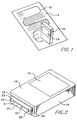
- Figs. 1-8 in general, illustrate a portable (hand-held) scanner 10 and a converter 110 therefor.
- the portable scanner 10 may be of the type having a scanner linear photosensor array 36, a scanner imaging assembly 22 which normally images a moving scan line portion of an adjacently positioned object 14 onto the linear photosensor array 36 as the portable scanner 10 is moved over the surface of the object 14 in close proximity thereto; a scanner navigation sensor assembly 24, 26 which senses movement of the portable scanner 10 over the scanned object 14; and a data processor 81 which receives and processes data from the linear photo sensor array 36 and the navigation sensor assembly 24, 26.
- the converter includes a converter imaging assembly 116, 128 having at least one optical element which cooperates with the scanner imaging assembly 22 to produce an image 37 of a scan line portion 115 of a scene 114 remote from the optical scanner 10 onto the scanner linear photosensor array 36.
- convertor 110 for a portable scanner 10 in general, convertors and associated scanners, both hand-held and flat bed, will now be described in detail.
- Figs. 1 and 2 illustrate a hand-held, portable scanning device 10 of the type which is described in detail in U.S. Patents 5,578,813 issued November 26, 1996 of Allen, et al. and 5,644,139 issued July 1, 1997 of Allen, et al., both of which are hereby specifically incorporated by reference for all that is disclosed therein.
- the hand scanner 10 is shown following a meandering path 12 across an original object 14 such as a printed paper document or the like.
- the scanner 10 may include an image display 16 which enables viewing of the image "scanned” or "captured" by the device.
- Fig. 2 shows the end portion 18 of the housing 19 of scanner 10 which is positioned in contact with original 14 as it is scanned.
- End portion 18 may include a base plate 20 having a plurality of window portions therein.
- the base plate 20 may pivot relative to the remainder of the scanner housing 19 to facilitate proper contact with the original.
- Elongated window portion 21 of an imaging assembly 22 extends between window portions 23, 25 of navigation sensor assembly 24, 26.
- FIG. 3 shows details of one embodiment of an imaging assembly in a slightly different hand-scanner configuration from that shown in Figs. 1 and 2 but in which the same reference numerals refer to corresponding components.
- Scanner housing 19 may comprise a back panel member 29 adapted to be connected to base plate 20.
- a light source for the imaging assembly 22 may be a linear LED array 30 which extends perpendicular to scan direction 31 and which may be mounted on an internal structural member 32 at a location above and slightly to one side of imaging window portion 21. Light from the LED array 30 passes through window portion 21, reflects off original 14, Fig. 1, and passes back through window portion 21. The reflected light then passes into an elongated gradient lens assembly 34 supported by member 32 at a location above window portion 21.
- the gradient lens assembly 34 may have a 1:1 reduction ratio.
- the lens assembly 34 projects a scan line image of the scanned object (original) 14 onto a linear photosensor array such as a contact image sensor 36 provided on a substrate 38. Substrate 38 may be located on top of structural member 32 with sensor array 36 positioned immediately above lens assembly 34 in contact therewith.
- Fig. 3 also shows details of navigation sensor assembly 24, 26.
- Navigation light sources 42, 44 may be positioned adjacent to each navigation window portion 23, 25 for directing light onto the original 14. The light is reflected from the original 14 back through window portions 23, 25 and thence through navigation lens assemblies 46, 48 onto two-dimensional photosensor arrays 52, 54.
- the navigation assembly two-dimensional photosensor arrays 52, 54 each capture a two-dimensional image of the portion of the original document 14 which is positioned immediately below window portions 23, 25, respectively.
- the sensors 52, 54 may be used to capture an image associated with physical characteristics of the document such as, for example, the surface roughness of the paper. Such surface roughness at high resolution may be as distinctive as a mountain range which is imaged by an overflying aircraft.
- the navigation sensor assembly 24, 26 sequentially capture images at predetermined intervals which have a fixed relationship to the operating interval of the linear photosensor assembly 36. By comparing the image taken at one operating interval to the image taken at the immediately following operating interval of each navigation sensor 52, 54 the relative linear and rotational displacement of the hand-held scanner 10 may be determined. These comparison calculations may be performed by a central data processor 80 which may comprise a microprocessor, Fig. 4, to which the signals of the navigation sensors 52, 54 are provided.
- the linear photosensor assembly array 36 captures an image of a scan line portion of the document 14 which is positioned immediately below it during each operating interval.
- Data from linear photosensor assembly 36 may be passed through an amplifier 82 and convertor 84 and provided to central data processor 80.
- the data from each operating interval of the linear photo sensor assembly 22 is tagged with position data indicative of the position of the linear photo sensor array on the document during that operating interval.
- the position data used is generated from the information provided by the navigation sensors 52, 54 during an associated operating interval of the linear photo sensor assembly 22.
- the position tagged image data stream 86 may thereafter be provided to processing electronics 87 including an image space memory having a plurality of memory locations which are filled with image data in accordance with the position tag applied to that image data.
- image data is properly arranged in memory so as to provide a composite image of the scanned document.
- other types of sensor devices such as, for example, mouse-ball type sensor devices may also be employed to generate data used to tag the image stream from the linear photosensor array 36.
- a portable scanner 10 having a converter 110 mounted thereon is illustrated in Fig. 5.
- This scanner-converter assembly 111 is supported on a table 112 and is used to image a scene 114, such as a whiteboard, remote from the scanner.
- An imaging light beam 113 extends from a scan line portion 115 of the scene 114 to the linear photosensor 36 of the scanner, Fig. 6.
- the scan line portion 115 of the scene is thus imaged on the photosensor 36 as indicated at 37.
- the converter contains a displacement assembly which causes the imaging light beam 113 to be swept across the scene to sequentially image a series of scan line portions of the scene which are converted to electronic data and stored in the scanner memory and which may subsequently be used to generate a complete image of the scene as, for example, on the display screen 16 of the scanner 10 or an associated printer (not shown).
- the converter 110 may be removeably connected to the scanner 10 by any attachment assembly such as for example bracket arms 130, 132 fixedly mounted on converter housing 122. Each bracket arm may have a free end adapted to receive a screw 134, 136 therein.
- the scanner housing 19 may comprise a pair of threaded holes (not shown) adapted to threadingly receive screws 134, 136 respectively for securing bracket arms 130, 132 to scanner housing 19, thereby holding the converter housing 122 in a predetermined registered relationship with the scanner housing.
- An other suitable attachment mechanism may also be used.
- a light reflecting surface such as a planar mirror 116 or a light refracting surface such as a prism (not shown) is mounted on a rotatable element such as a shaft 118 having an axis of rotation AA extending perpendicular to the ordinary direction of scanning movement 31, Fig. 3, of the scanner.
- the shaft 118 is operably drivingly connected to a drive motor 120.
- the motor may be fixedly mounted on a converter housing 122.
- the shaft 118 may be an extension of the motor drive shaft.
- Housing 122 may be constructed for metal, high strength plastic, composite or other suitable material.
- Housing 122 has a closed generally parallelepiped shaped wall structure with a first opening 140, a second opening 141, a third opening 143, and a fourth opening 145, Fig. 6, therein.
- First opening 140 is adapted to allow imaging light from remote scene 114 into the housing 122.
- Second opening 141 is position in alignment with and next adjacent to scanner window 21.
- Third and fourth openings 143 and 145 are positioned in alignment with and next adjacent to navigation assembly windows 23, 25, respectively
- Wheels 124, 126 may be fixedly mounted on shaft 118. Each wheel may have a rough circumferential surface 125, 127 which is adapted to be sensed through windows in the converter housing and the scanner housing by an aligned two dimensional sensor array 52, 54.
- the circumferential surfaces have linear velocities proportionate to the rotation rate of shaft 118 and mirror 116.
- the imaging light beam 113 from the remote scene 114 passes through converter window 140, Fig. 6, and is reflected from rotatable mirror 116. It then passes through converter optical elements shown schematically at 128 in Fig. 6.
- the converter optical elements 128 are adapted to coact with the scanner optical elements 22 (shown only in schematic block form in Fig. 6) to produce a focused image 37 of scan line portion 115 on the scanner linear sensor array 36.
- One embodiment of the converter optical elements 128 is illustrated in Fig. 7. In that embodiment the optical elements comprise a fixed mirror 142 and a fixed lens element 146 both having lengths extending parallel to the length of the linear sensor array 36 and rotation axis AA (i.e. into the sheet in Fig. 7).
- Rotating mirror 116 and fixed mirror 142 coact to fold the path of imaging light beam 113.
- the lens 122 may have a length approximately equal to the length of the gradient lens 34.
- the combined optical effect of lens 122 and gradient lens 34 is to produce a focused image of a subject scan line 115 on the linear sensor array 36.
- the reduction ratio of object size to image size is dependent in part upon the ratio of the length of the portion of the imaging light beam 115 between the scene 114 and lens 146 and the length of the imaging light beam portion between lens 146 and the scanner window portion 21.
- the reduction ratio for an imaged scene located 10 feet away from the converter 110 may be 10:1.
- mirror 116 is rotated about axis AA of shaft 118, thereby causing a series of scan line portions 115, 117, etc. of remote scene 114 to be sweepingly imaged on linear photosensor array 36.
- Fig. 7 shows one rotational position of the mirror 116 and the corresponding imaging light path 113 along axis XX from one scan line portion 115 of the scene 114 in solid lines and shows another rotational position of the mirror 116 and the corresponding imaging light path 113 along axis YY from another scan line portion 117 of the scene 114 in dashed lines.
- the amount that the mirror must be angularly displaced in order to completely scan a distant scene depends of course on the size of the scene to be scanned and the distance of the scene from the scanner 10.
- each scene with the same amount of angular displacement of the mirror 16.
- One exemplary amount of displacement is 45 degrees.
- To perform a scan the mirror is initially positioned at the location indicated by axis YY in Fig. 7. The mirror is then rotated in mirror rotation direction 150 through the position indicated at XX to an end of cycle position (axis not shown) above axis XX.
- the end of cycle position may be displaced angularly from XX by an amount equal to the angle formed by XX and YY.
- the scanner navigation assembly sequentially images at least one of the wheels 124, 126 with at least one of its navigation sensors 52, 54 and generates position data in the same manner that the navigation system generates position data when the scanner is moved across a document.
- This changing position data indicates the circumferential displacement of the associated wheel 124, 126.
- the diameter of the wheels are known, thus this circumferential position/displacement data generated by the navigation sensors may be used to determine the circumferential displacement of the wheels and thence the angular position/displacement of shaft 118 and mirror 116.
- Mirror angular position coordinates determined during a subject operating interval of the scanner linear photosensor 36 are used to tag the data from the linear photosensor during that operating interval in the same manner that rectangular coordinates from the navigation sensor assembly are use to tag linear photosensor data during hand scanning.
- the data tagging task is simplified when using the converter 110 because motion occurs in only one dimension. Thus information from only one of the navigation sensors is required for generating the tagging data.
- the tagging coordinate information is used to properly order the tagged linear photosensor data in memory to enable generation of a composite image of the scanned scene in the same manner that tagged data is used in hand scanning.
- motor 120 may be a stepper motor assembly which provides an output signal to central data processor 81 and which is, in turn, controlled by command signals from processor 81.
- the stepper motor assembly output signal is indicative of the angular position of mirror 116.
- the position data is also put to another use. It is used to determine when the shaft has reached the end of its displacement cycle and thus when to terminate motor displacement in a direction 150.
- the motor is operated in the reverse direction until the mirror 116 has been rotated to the start-cycle angular position shown in dashed lines in Fig. 7. (Alternatively, the mirror 116 could continue rotating in direction 150 until reaching the start cycle position.)
- the navigation sensor signals (or stepper motor signals) are again used to determine when the start-cycle operating position has been reached at which point the motor operation is again terminated. The mirror then remains in this position until the beginning of the next scanning session at which time it is again displaced in direction 150.
- the opening or window 140 which allows imaging light to enter the converter housing is positioned diametrically opposite (along axis XX) the opening 141 through which imaging light passes to leave the converter and enter the scanner window 21.
- the opening 141 which is positioned next to scanner window 21 faces perpendicular to the direction in which opening 140 faces.
- mirror 116 as in the previous embodiment, is rotated to produce a sweeping scan line image on the linear sensor (not shown in Fig. 8) but mirror 142 may be eliminated.
- fixed lens 146 has been replaced by a zoom lens assembly 148 positioned in opening 140.
- Zoom lens 148 may be conventionally manually operated to increase or decrease the size of the scan line image which is focused on linear sensor 36.
- Anular position sensing and data tagging of scan lines may be the same as described with reference to Figs. 6 and 7 above.
- Fig. 9 illustrates a flat bed scanner 160 having a housing 161 and a cover 162 which covers the scanner platen or transparent plate 164.
- the cover has an opening 166 extending perpendicular to the scanning direction and extending entirely through the cover 162. This opening is covered by a plug (not shown) or other light blocking structure during ordinary scanner operation. However when this flat bed scanner is used with a converter 180 opening 166 is uncovered.
- the flat bed scanner further includes a scanner imaging carriage 172 which is ordinarily displaceable along parallel rails 174 (only one shown) to produce displacement between the imaging assembly 172 and a document (not shown) placed on the platen 164.
- the carriage assembly includes an optical imaging assembly and a linear photosensor assembly (not shown) which may be the same or similar to those of the flat bed scanner patents incorporated by reference above, which coact to scan a document placed on the scanner platen.
- the scanner may be of the type having a "trombone" type light path and in which the photosensor assembly is positioned in a fixed location remote from the scanner carriage, as is conventional and known in the art.
- the scanner 160 has a central processing unit which processes data signals received from a linear photosensor assembly and thereafter transmits processed data signals representative of the scanned document to a memory or display device as is well known in the art.
- a converter 180 is provided which may have the same components shown in Fig. 8 except that the converter mirror drive motor 120 is a stepper motor which includes a stepper motor angular position sensor 190.
- the converter is mounted in stationary relationship with the scanner 160 on top of cover 162 with imaging light exit opening 141 of the scanner aligned with slit 166 of the cover and coextensive therewith.
- the scanner 160 may be provided with appropriate circuitry/software and a selection device, such as a push-button (not shown) for parking the scanner carriage 172 directly beneath slit 166 and initiating converter mode operation of the scanner.
- An electrical lead 192 is operably connected between the converter stepper motor angular position sensor 190 and the scanner central processing unit 176 to provide a signal to the processing unit 176 indicative of scanner mirror position and to provide command signals to actuate the stepper motor.
- the signal provided by position sensor 190 replaces the position feedback signals from navigation sensors as described above.
- the processing unit 176 may thus operate in the same manner as central data processor 81 described above in order to generate image data representative of a remote scene 114.
- the scanner converters 110 and 190 described above may be operated at a single, preset operating speed which takes into account worst case lighting conditions. However the converters may also be configured to operate at a plurality of different operating speeds which are selected based upon current lighting conditions. This speed selection is done, as indicated in Fig. 10, by performing an initial fast scan and using the photosensor light intensity values from that fast scan to determine current lighting conditions and then choosing the optimum speed for the final scan based upon predetermined look-up table values or the like.
Abstract
Description
- The present invention relates generally to optical scanners which are used to scan a closely adjacently positioned object such as a document and, more particularly, to a converter for an optical scanner which enables the scanner to scan a scene remote from the scanner.
- Optical scanners which create electronic data representative of an image of a scanned object are known in the art. Flat bed scanners are stationary devices which have a transparent plate or platen upon which an object to be scanned, such as a paper document, is placed. The document is scanned by sequentially imaging narrow strip or scan line portions of the document on a linear optical sensor array such as a charge coupled device (CCD). The optical sensor array produces electronic data which is representative of each scan line portion of the document which is imaged thereon. In one type of flat bed scanner the current scan line portion of the document which is imaged on the sensor array is changed or "swept" by moving the platen supporting the document relative to the scanner imaging assembly. In another type of flat bed scanner the platen and document remain stationary and at least a portion of a imaging assembly is moved to change the scan line portion which is currently imaged. Flat bed scanners of the second type are sometimes provided with automatic document feeders (ADFs) which sequentially move sheet documents across a portion of the scanner platen. When an ADF is used, the portion of the imaging assembly which ordinarily moves during scanning remains stationary and relative movement between the document and imaging assembly is provided by the ADF. Flat bed scanners and ADF's are disclosed in the following patents, each of which is hereby incorporated by reference for all that is disclosed therein: Boyd et al., U.S. Patent 4,926,041; Boyd et al., U.S. Patent 5,336,878; Henry et al., U.S. Patent 5,339,107, Steinle et al., U.S. Patent 5,410,347; and Steinle et al., U.S. Patent 5,646,394.
- Portable or hand scanners, like flat bed scanners, generate electronic data representative of an image of an object by sequentially imaging scan line portions of the object. However hand scanners differ from flat bed scanners in that hand scanners produce relative movement between the scanned object and the scanner imaging assembly by displacing the entire scanner relative to the document. Hand scanners generally have an end portion which is adapted to be positioned in contact with the object which is to be scanned. An operator moves the scanner over the object keeping this end portion in contact with the object. Since the displacement between the scanner and the object is provided by the user rather than a fixed speed drive assembly such as contained on a flat bed scanner, a displacement sensing assembly is usually provided on a hand scanner in order to properly correlate and arrange the sequential scan line image data generated by the optical sensor array to enable reproduction of an accurate composite image of the object. Hand scanners and displacement sensing systems or navigation systems therefore are disclosed in the following patents, each of which is hereby specifically incorporated by reference for all that is disclosed therein: Allen et al., U.S. Patent 5,644,139; McConica et al., U.S. Patent 5,586,212 Allen et al., U.S. Patent 5,578,831; Kochis et al., U.S. Patent 5,381,020; McConica et al., U.S. Patent 5,306,908; Reymond et al., U.S. Patent 4,494,201; Postl, U.S. Patent 4,723,297; Mongomery et al., U.S. Patent 4,797,544; Hollister, U.S. Patent 4,951,214; Abramovitz et al., U.S. Patent 5,023,922; Holland, U.S. Patent 5,089,712; Sobol, U.S. Patent 5,185,673; Chiu et al., U.S. Patent 5,355,146; and Kimura et al., U.S. Patent 5,497,150.
- Both flat bed scanners and hand scanners used to date require that an object which is to be imaged be positioned in touching contact with or in very close proximity with the object which is scanned. It would be generally desirable to provide a converter which would enable a flat bed scanner or a portable scanner to be used to scan objects positioned remotely from the scanner. It would be particularly desirable to provide such a converter for a portable scanner to enable the scanner to be used, in effect, as a portable digital camera as well as a portable optical scanner.
- The present invention is directed to a converter for a scanner of the type which ordinarily is positioned in touching or near touching contact with an object to be scanned. The converter enables the scanner to scan a scene positioned remotely from the scanner.
- Thus the invention may comprise a converter for an optical scanner of the type having a scanner linear photosensor array, a scanner imaging assembly which normally images a moving scan line portion of a closely adjacently positioned object onto the linear photosensor array. The converter includes a converter imaging assembly having at least one optical element which cooperates with the scanner imaging assembly to image a scan line portion of a scene remote from said optical scanner onto the scanner linear photosensor array.
- The invention may also comprise a method of using a scanner, which is ordinarily used to scan an object positioned in close proximity to the scanner, to scan a scene which is positioned remotely from the scanner. The method may include maintaining the scanner at a fixed position relative to the scene and directing imaging light reflected from a first portion of the scene onto a predetermined portion of the scanner and, while maintaining the scanner at the fixed position relative to the scene, directing imaging light reflected from a second portion of the scene adjacent to the first portion of the scene onto the predetermined portion of the scanner.
- The invention may also comprise a method of converting a proximate object optical scanner of the type having a linear photosensor array and an imaging assembly which normally images a moving scan line portion of a closely adjacently positioned object onto the linear photosensor array, into a remote scene scanner comprising attaching to the optical scanner a converter imaging assembly having at least one optical element which cooperates with the scanner imaging assembly to image a scan line portion of a scene remote from said optical scanner onto said scanner linear photosensor array.
-
- Fig. 1 is a schematic perspective view of a hand-held (portable) optical scanner being moved across a document in a serpentine path;
- Fig. 2 is a schematic perspective view of the hand-held optical scanner of Fig. 1 positioned to expose a portion of the imaging assembly and navigation assembly thereof;
- Fig. 3 is an exploded perspective view of one specific embodiment of a hand-held optical scanner of the type shown schematically in Figs. 1 and 2, showing portions of the imaging assembly and the navigation system thereof;
- Fig. 4 is a block diagram illustrating the processing of sensor signals from navigation sensors and a linear photosensor array of a hand-held optical scanner;
- Fig. 5 is a perspective view of a hand-held optical scanner, equipped with a convertor, being used to image a scene positioned remotely from the scanner;
- Fig. 6 is a schematic illustration of the operating components of a hand-held optical scanner and the operating components of a convertor for a hand-held optical scanner;
- Fig. 7 is a schematic, cross-sectional, side elevation view of one configuration of a convertor for a hand-held optical scanner;
- Fig. 8 is a schematic, cross-sectional, side elevation view of another embodiment of a convertor for a hand-held optical scanner;
- Fig. 9 is a schematic, cross-sectional, side elevation view of a flat bed scanner equipped with a convertor being used to scan a scene positioned remote from the flat bed scanner;
- Fig. 10 is a block diagram showing a light calibration process performed by an optical scanner equipped with a convertor.
-
- Figs. 1-8, in general, illustrate a portable (hand-held)
scanner 10 and aconverter 110 therefor. Theportable scanner 10 may be of the type having a scannerlinear photosensor array 36, ascanner imaging assembly 22 which normally images a moving scan line portion of an adjacently positionedobject 14 onto thelinear photosensor array 36 as theportable scanner 10 is moved over the surface of theobject 14 in close proximity thereto; a scannernavigation sensor assembly portable scanner 10 over the scannedobject 14; and adata processor 81 which receives and processes data from the linearphoto sensor array 36 and thenavigation sensor assembly converter imaging assembly scanner imaging assembly 22 to produce animage 37 of ascan line portion 115 of ascene 114 remote from theoptical scanner 10 onto the scannerlinear photosensor array 36. - Having thus described a
convertor 110 for aportable scanner 10 in general, convertors and associated scanners, both hand-held and flat bed, will now be described in detail. - Figs. 1 and 2 illustrate a hand-held,
portable scanning device 10 of the type which is described in detail in U.S. Patents 5,578,813 issued November 26, 1996 of Allen, et al. and 5,644,139 issued July 1, 1997 of Allen, et al., both of which are hereby specifically incorporated by reference for all that is disclosed therein. Thehand scanner 10 is shown following ameandering path 12 across anoriginal object 14 such as a printed paper document or the like. Thescanner 10 may include animage display 16 which enables viewing of the image "scanned" or "captured" by the device. - Fig. 2 shows the
end portion 18 of thehousing 19 ofscanner 10 which is positioned in contact with original 14 as it is scanned.End portion 18 may include abase plate 20 having a plurality of window portions therein. In one embodiment thebase plate 20 may pivot relative to the remainder of thescanner housing 19 to facilitate proper contact with the original. Elongatedwindow portion 21 of animaging assembly 22 extends betweenwindow portions navigation sensor assembly - Fig. 3 shows details of one embodiment of an imaging assembly in a slightly different hand-scanner configuration from that shown in Figs. 1 and 2 but in which the same reference numerals refer to corresponding components.
-
Scanner housing 19 may comprise aback panel member 29 adapted to be connected tobase plate 20. A light source for theimaging assembly 22 may be alinear LED array 30 which extends perpendicular to scandirection 31 and which may be mounted on an internalstructural member 32 at a location above and slightly to one side ofimaging window portion 21. Light from theLED array 30 passes throughwindow portion 21, reflects off original 14, Fig. 1, and passes back throughwindow portion 21. The reflected light then passes into an elongatedgradient lens assembly 34 supported bymember 32 at a location abovewindow portion 21. Thegradient lens assembly 34 may have a 1:1 reduction ratio. Thelens assembly 34 projects a scan line image of the scanned object (original) 14 onto a linear photosensor array such as acontact image sensor 36 provided on asubstrate 38.Substrate 38 may be located on top ofstructural member 32 withsensor array 36 positioned immediately abovelens assembly 34 in contact therewith. - Fig. 3 also shows details of
navigation sensor assembly Navigation light sources navigation window portion window portions dimensional photosensor arrays dimensional photosensor arrays original document 14 which is positioned immediately belowwindow portions sensors - The
navigation sensor assembly linear photosensor assembly 36. By comparing the image taken at one operating interval to the image taken at the immediately following operating interval of eachnavigation sensor scanner 10 may be determined. These comparison calculations may be performed by acentral data processor 80 which may comprise a microprocessor, Fig. 4, to which the signals of thenavigation sensors - As previously mentioned, the linear
photosensor assembly array 36 captures an image of a scan line portion of thedocument 14 which is positioned immediately below it during each operating interval. Data fromlinear photosensor assembly 36 may be passed through anamplifier 82 andconvertor 84 and provided tocentral data processor 80. The data from each operating interval of the linearphoto sensor assembly 22 is tagged with position data indicative of the position of the linear photo sensor array on the document during that operating interval. The position data used is generated from the information provided by thenavigation sensors photo sensor assembly 22. The position taggedimage data stream 86 may thereafter be provided toprocessing electronics 87 including an image space memory having a plurality of memory locations which are filled with image data in accordance with the position tag applied to that image data. In this manner, image data is properly arranged in memory so as to provide a composite image of the scanned document. As an alternative to position data generated bynavigation sensors linear photosensor array 36. - A
portable scanner 10 having aconverter 110 mounted thereon is illustrated in Fig. 5. This scanner-converter assembly 111 is supported on a table 112 and is used to image ascene 114, such as a whiteboard, remote from the scanner. Animaging light beam 113 extends from ascan line portion 115 of thescene 114 to thelinear photosensor 36 of the scanner, Fig. 6. Thescan line portion 115 of the scene is thus imaged on the photosensor 36 as indicated at 37. The converter contains a displacement assembly which causes theimaging light beam 113 to be swept across the scene to sequentially image a series of scan line portions of the scene which are converted to electronic data and stored in the scanner memory and which may subsequently be used to generate a complete image of the scene as, for example, on thedisplay screen 16 of thescanner 10 or an associated printer (not shown). - The basic operating components of the
converter 110 and the interaction thereof with the operating components of theportable scanner 10 is illustrated schematically in Figs. 6 and 7. - The
converter 110 may be removeably connected to thescanner 10 by any attachment assembly such as forexample bracket arms converter housing 122. Each bracket arm may have a free end adapted to receive ascrew scanner housing 19 may comprise a pair of threaded holes (not shown) adapted to threadingly receivescrews bracket arms scanner housing 19, thereby holding theconverter housing 122 in a predetermined registered relationship with the scanner housing. An other suitable attachment mechanism may also be used. - A light reflecting surface such as a
planar mirror 116 or a light refracting surface such as a prism (not shown) is mounted on a rotatable element such as ashaft 118 having an axis of rotation AA extending perpendicular to the ordinary direction ofscanning movement 31, Fig. 3, of the scanner. Theshaft 118 is operably drivingly connected to adrive motor 120. The motor may be fixedly mounted on aconverter housing 122. Theshaft 118 may be an extension of the motor drive shaft. -
Housing 122 may be constructed for metal, high strength plastic, composite or other suitable material.Housing 122 has a closed generally parallelepiped shaped wall structure with afirst opening 140, asecond opening 141, athird opening 143, and afourth opening 145, Fig. 6, therein.First opening 140 is adapted to allow imaging light fromremote scene 114 into thehousing 122.Second opening 141 is position in alignment with and next adjacent toscanner window 21. Third andfourth openings navigation assembly windows -
Wheels shaft 118. Each wheel may have a roughcircumferential surface dimensional sensor array shaft 118 andmirror 116. - The
imaging light beam 113 from theremote scene 114 passes throughconverter window 140, Fig. 6, and is reflected fromrotatable mirror 116. It then passes through converter optical elements shown schematically at 128 in Fig. 6. The converteroptical elements 128 are adapted to coact with the scanner optical elements 22 (shown only in schematic block form in Fig. 6) to produce afocused image 37 ofscan line portion 115 on the scannerlinear sensor array 36. One embodiment of the converteroptical elements 128 is illustrated in Fig. 7. In that embodiment the optical elements comprise a fixedmirror 142 and a fixedlens element 146 both having lengths extending parallel to the length of thelinear sensor array 36 and rotation axis AA (i.e. into the sheet in Fig. 7). Rotatingmirror 116 and fixedmirror 142 coact to fold the path ofimaging light beam 113. In an embodiment in which theoptical scanner 10 employs a gradient lens type optical system, as shown in Fig. 3, thelens 122 may have a length approximately equal to the length of thegradient lens 34. The combined optical effect oflens 122 andgradient lens 34 is to produce a focused image of asubject scan line 115 on thelinear sensor array 36. The reduction ratio of object size to image size is dependent in part upon the ratio of the length of the portion of theimaging light beam 115 between thescene 114 andlens 146 and the length of the imaging light beam portion betweenlens 146 and thescanner window portion 21. In one preferred embodiment the reduction ratio for an imaged scene located 10 feet away from theconverter 110 may be 10:1. - In
operation mirror 116 is rotated about axis AA ofshaft 118, thereby causing a series ofscan line portions remote scene 114 to be sweepingly imaged onlinear photosensor array 36. Fig. 7 shows one rotational position of themirror 116 and the correspondingimaging light path 113 along axis XX from onescan line portion 115 of thescene 114 in solid lines and shows another rotational position of themirror 116 and the correspondingimaging light path 113 along axis YY from anotherscan line portion 117 of thescene 114 in dashed lines. The amount that the mirror must be angularly displaced in order to completely scan a distant scene depends of course on the size of the scene to be scanned and the distance of the scene from thescanner 10. However it is generally desirable to, at least initially, scan each scene with the same amount of angular displacement of themirror 16. One exemplary amount of displacement is 45 degrees. To perform a scan the mirror is initially positioned at the location indicated by axis YY in Fig. 7. The mirror is then rotated inmirror rotation direction 150 through the position indicated at XX to an end of cycle position (axis not shown) above axis XX. The end of cycle position may be displaced angularly from XX by an amount equal to the angle formed by XX and YY. - During angular displacement of the mirror the scanner navigation assembly sequentially images at least one of the
wheels navigation sensors wheel shaft 118 andmirror 116. Mirror angular position coordinates determined during a subject operating interval of the scannerlinear photosensor 36 are used to tag the data from the linear photosensor during that operating interval in the same manner that rectangular coordinates from the navigation sensor assembly are use to tag linear photosensor data during hand scanning. The data tagging task is simplified when using theconverter 110 because motion occurs in only one dimension. Thus information from only one of the navigation sensors is required for generating the tagging data. The tagging coordinate information is used to properly order the tagged linear photosensor data in memory to enable generation of a composite image of the scanned scene in the same manner that tagged data is used in hand scanning. (As an alternative to usingnavigation sensors motor 120 may be a stepper motor assembly which provides an output signal tocentral data processor 81 and which is, in turn, controlled by command signals fromprocessor 81. The stepper motor assembly output signal is indicative of the angular position ofmirror 116.) - During converter operation the position data is also put to another use. It is used to determine when the shaft has reached the end of its displacement cycle and thus when to terminate motor displacement in a
direction 150. After displacement indirection 150 has been stopped the motor is operated in the reverse direction until themirror 116 has been rotated to the start-cycle angular position shown in dashed lines in Fig. 7. (Alternatively, themirror 116 could continue rotating indirection 150 until reaching the start cycle position.) The navigation sensor signals (or stepper motor signals) are again used to determine when the start-cycle operating position has been reached at which point the motor operation is again terminated. The mirror then remains in this position until the beginning of the next scanning session at which time it is again displaced indirection 150. - In the embodiment of the
converter 110 illustrated in Fig. 7, the opening orwindow 140 which allows imaging light to enter the converter housing is positioned diametrically opposite (along axis XX) theopening 141 through which imaging light passes to leave the converter and enter thescanner window 21. In the embodiment of theconverter 110 illustrated in Fig. 8, theopening 141 which is positioned next toscanner window 21 faces perpendicular to the direction in whichopening 140 faces. In thisarrangement mirror 116, as in the previous embodiment, is rotated to produce a sweeping scan line image on the linear sensor (not shown in Fig. 8) butmirror 142 may be eliminated. Also in Fig. 8, fixedlens 146 has been replaced by azoom lens assembly 148 positioned inopening 140.Zoom lens 148 may be conventionally manually operated to increase or decrease the size of the scan line image which is focused onlinear sensor 36. Anular position sensing and data tagging of scan lines may be the same as described with reference to Figs. 6 and 7 above. - Fig. 9 illustrates a
flat bed scanner 160 having ahousing 161 and acover 162 which covers the scanner platen ortransparent plate 164. The cover has anopening 166 extending perpendicular to the scanning direction and extending entirely through thecover 162. This opening is covered by a plug (not shown) or other light blocking structure during ordinary scanner operation. However when this flat bed scanner is used with aconverter 180opening 166 is uncovered. The flat bed scanner further includes ascanner imaging carriage 172 which is ordinarily displaceable along parallel rails 174 (only one shown) to produce displacement between theimaging assembly 172 and a document (not shown) placed on theplaten 164. The carriage assembly includes an optical imaging assembly and a linear photosensor assembly (not shown) which may be the same or similar to those of the flat bed scanner patents incorporated by reference above, which coact to scan a document placed on the scanner platen. Alternatively, the scanner may be of the type having a "trombone" type light path and in which the photosensor assembly is positioned in a fixed location remote from the scanner carriage, as is conventional and known in the art. Thescanner 160 has a central processing unit which processes data signals received from a linear photosensor assembly and thereafter transmits processed data signals representative of the scanned document to a memory or display device as is well known in the art. - In the illustration of Fig. 9, a
converter 180 is provided which may have the same components shown in Fig. 8 except that the convertermirror drive motor 120 is a stepper motor which includes a stepper motorangular position sensor 190. The converter is mounted in stationary relationship with thescanner 160 on top ofcover 162 with imaging light exit opening 141 of the scanner aligned withslit 166 of the cover and coextensive therewith. Thescanner 160 may be provided with appropriate circuitry/software and a selection device, such as a push-button (not shown) for parking thescanner carriage 172 directly beneathslit 166 and initiating converter mode operation of the scanner. Anelectrical lead 192 is operably connected between the converter stepper motorangular position sensor 190 and the scannercentral processing unit 176 to provide a signal to theprocessing unit 176 indicative of scanner mirror position and to provide command signals to actuate the stepper motor. The signal provided byposition sensor 190 replaces the position feedback signals from navigation sensors as described above. Theprocessing unit 176 may thus operate in the same manner ascentral data processor 81 described above in order to generate image data representative of aremote scene 114. - The
scanner converters - It is contemplated that the inventive concepts herein described may be variously otherwise embodied and it is intended that the appended claims be construed to include alternative embodiments of the invention, except insofar as limited by the prior art.
Claims (10)
- A Converter (110) for an optical scanner (10) of the type having a scanner linear photosensor array (36), a scanner imaging assembly (22) which normally images a moving scan line portion of a closely adjacently positioned object (14) onto the linear photosensor array (36) comprising:a converter imaging assembly (116,128) having at least one optical element (116) which cooperates with the scanner imaging assembly (22) to image a scan line portion (115) of a scene (114) remote from said optical scanner (10) onto said scanner linear photosensor array (36).
- The converter (110) of claim 1 further comprising:a converter displacement assembly (120) which displaces at least one optical element (116) of said converter imaging assembly (116,128) to sweepingly change said scan line portion (115) of the scene (114) which is imaged on the linear photosensor array 36 without moving the optical scanner (10) with respect to the scene (114).
- The converter of claim 2 wherein the optical scanner (10) is a portable scanner adapted to be moved over the surface of an object (14) to scan the object, the portable scanner (10) comprising a scanner navigation sensor assembly (24) which senses movement of the portable scanner (10) over the scanned object (14) and a data processor (81) which receives and processes data from the linear photosensor array (36) and the navigation sensor assembly (24) and comprising:a scan line displacement sensing assembly (24,120) which senses said sweeping change of said scan line portion (115) of the scene (114) and generates a sensing signal representative thereof which is provided to the portable scanner data processor (81).
- The converter of claim 3 wherein said scan line displacement sensing assembly comprises a stepper motor (120).
- The converter (110) of claim 2 wherein said scan line displacement sensing assembly comprises at least a portion of said scanner navigation sensor assembly (24).
- The converter of claim 5 wherein said scanner navigation assembly (24) comprises a surface sensing, optical navigation sensor assembly and further comprising a rotating surface (124) having a surface speed dependent upon said scan line sweep rate disposed in surface detectable relationship with said optical navigation sensor assembly.
- The converter of any of claims 2 through 6, said portable scanner (10) comprising a scanner housing (19) which houses said scanner linear photosensor array (36), said scanner imaging assembly (22), said scanner navigator sensor assembly (24), and said scanner data processor (81), said converter (110) comprising a converter housing (122) which houses said converter imaging assembly (116,128) and said converter displacement assembly (120), said converter housing (122) being removably attachable to said scanner housing (19).
- A method of using a scanner (10), which is ordinarily used to scan an object (14) positioned in close proximity to the scanner (10), to scan a scene (114) which is positioned remotely from the scanner (10) comprising:maintaining said scanner (10) at a fixed position relative to said scene (114) and directing imaging light reflected from a first portion of said scene (115) onto a predetermined portion (22) of said scanner (10); andwhile maintaining said scanner (10) at said fixed position relative to said scene (114), directing imaging light reflected from a second portion of said scene (114) adjacent to said first portion (115) of said scene onto said predetermined portion of said scanner (22).
- The method of claim 8, further comprising:sensing relative displacement between said first portion (115) of said scene (114) and said second portion of said scene.
- The method of claim 9 wherein said sensing of displacement comprises sensing of displacement with a scanner onboard navigation sensor assembly (24) which is ordinarily used to sense displacement of the scanner over the surface of a document (14) positioned in contact with the scanner (10).
Applications Claiming Priority (2)
| Application Number | Priority Date | Filing Date | Title |
|---|---|---|---|
| US143686 | 1998-08-28 | ||
| US09/143,686 US6330082B1 (en) | 1998-08-28 | 1998-08-28 | Converter for optical scanner |
Publications (2)
| Publication Number | Publication Date |
|---|---|
| EP0982923A2 true EP0982923A2 (en) | 2000-03-01 |
| EP0982923A3 EP0982923A3 (en) | 2001-09-05 |
Family
ID=22505149
Family Applications (1)
| Application Number | Title | Priority Date | Filing Date |
|---|---|---|---|
| EP99111338A Withdrawn EP0982923A3 (en) | 1998-08-28 | 1999-06-10 | Converter for optical scanner |
Country Status (5)
| Country | Link |
|---|---|
| US (1) | US6330082B1 (en) |
| EP (1) | EP0982923A3 (en) |
| JP (1) | JP3665514B2 (en) |
| SG (1) | SG77252A1 (en) |
| TW (1) | TW420922B (en) |
Cited By (2)
| Publication number | Priority date | Publication date | Assignee | Title |
|---|---|---|---|---|
| EP1518695A3 (en) * | 2003-09-25 | 2008-07-30 | Hewlett-Packard Development Company, L.P. | Method and system for printhead rotation detection using photosensors |
| US8179382B2 (en) | 2003-05-30 | 2012-05-15 | Steelcase Development Corporation | Visual communication system |
Families Citing this family (12)
| Publication number | Priority date | Publication date | Assignee | Title |
|---|---|---|---|---|
| US6880124B1 (en) * | 1999-06-04 | 2005-04-12 | Hewlett-Packard Development Company, L.P. | Methods of storing and retrieving information, and methods of document retrieval |
| US6904182B1 (en) * | 2000-04-19 | 2005-06-07 | Microsoft Corporation | Whiteboard imaging system |
| TW477508U (en) * | 2000-06-22 | 2002-02-21 | Umax Data Systems Inc | scanning device |
| US7583416B2 (en) * | 2001-12-20 | 2009-09-01 | Eastman Kodak Company | Document scanning system with tethered platen element providing sheet-fed and platen scanning functions |
| US6904326B2 (en) * | 2002-10-17 | 2005-06-07 | Hewlett-Packard Development Company, Lp. | Light responsive data entry system |
| CN100527773C (en) * | 2003-11-04 | 2009-08-12 | 武汉矽感科技有限公司 | Scanner having alignment sensor and its process method for image acquisition |
| US8488211B2 (en) * | 2006-11-07 | 2013-07-16 | Colin Mark Ruskin | Device, system and method for portable data scanning and transmission |
| JP4653123B2 (en) * | 2007-01-09 | 2011-03-16 | 富士フイルム株式会社 | Image acquisition apparatus and image acquisition method |
| JP5146306B2 (en) * | 2008-12-26 | 2013-02-20 | セイコーエプソン株式会社 | Document reader |
| TWI631600B (en) * | 2017-05-26 | 2018-08-01 | 緯創資通股份有限公司 | Optical device |
| WO2019152024A1 (en) * | 2018-01-31 | 2019-08-08 | Hewlett-Packard Development Company, L.P. | Rotatable scanner image sensors within sealed enclosures |
| JPWO2021084761A1 (en) * | 2019-11-01 | 2021-05-06 |
Citations (4)
| Publication number | Priority date | Publication date | Assignee | Title |
|---|---|---|---|---|
| US4882629A (en) * | 1987-05-08 | 1989-11-21 | Everex Ti Corporation | Adaptive exposure control system |
| US4887165A (en) * | 1987-05-25 | 1989-12-12 | Hitachi, Ltd. | Document editing apparatus having detachable image reader |
| US5410141A (en) * | 1989-06-07 | 1995-04-25 | Norand | Hand-held data capture system with interchangable modules |
| US5414251A (en) * | 1992-03-12 | 1995-05-09 | Norand Corporation | Reader for decoding two-dimensional optical information |
Family Cites Families (23)
| Publication number | Priority date | Publication date | Assignee | Title |
|---|---|---|---|---|
| FR2504673A1 (en) | 1981-04-27 | 1982-10-29 | Thomson Csf | CARTOGRAPHIC INDICATOR RECORDED ON PHOTOGRAPHIC FILM |
| US4723297A (en) | 1984-09-27 | 1988-02-02 | Siemens Aktiengesellschaft | Method for automatic correction of character skew in the acquisition of a text original in the form of digital scan results |
| US5023922A (en) | 1985-06-07 | 1991-06-11 | Soricon Corporation | Optical character reader |
| EP0242403B1 (en) * | 1986-03-25 | 1990-11-22 | Ibm Deutschland Gmbh | Endless rotary belts with compensation for a shift perpendicular to their moving direction |
| US4797544A (en) | 1986-07-23 | 1989-01-10 | Montgomery James R | Optical scanner including position sensors |
| JPS6425265U (en) * | 1987-08-06 | 1989-02-13 | ||
| US4951214A (en) | 1988-11-18 | 1990-08-21 | Texas Instruments Incorporated | Method for passively determining the relative position of a moving observer with respect to a stationary object |
| US5089712A (en) | 1989-06-08 | 1992-02-18 | Hewlett-Packard Company | Sheet advancement control system detecting fiber pattern of sheet |
| US4926041A (en) | 1989-07-20 | 1990-05-15 | Hewlett-Packard Company | Optical scanner |
| US5355146A (en) | 1990-03-05 | 1994-10-11 | Bmc Micro-Industries Ltd. | Multi-directional hand scanner and mouse |
| US5185673A (en) | 1991-06-12 | 1993-02-09 | Hewlett-Packard Company | Automated image calibration |
| US5410347A (en) | 1992-08-19 | 1995-04-25 | Hewlett-Packard Company | Color optical scanner with image registration holding assembly |
| US5339107A (en) | 1992-08-19 | 1994-08-16 | Hewlett-Packard Company | Color optical scanner with rotating color filter assembly |
| JP3311414B2 (en) * | 1993-03-01 | 2002-08-05 | 株式会社リコー | Image reading device |
| US5306908A (en) | 1993-03-15 | 1994-04-26 | Hewlett-Packard Company | Manually operated hand-held optical scanner with tactile speed control assembly |
| US5381020A (en) | 1993-03-31 | 1995-01-10 | Hewlett-Packard Company | Hand-held optical scanner with onboard battery recharging assembly |
| US5497150A (en) | 1993-04-05 | 1996-03-05 | Smk Corporation | Image scanner |
| US5336878A (en) | 1993-05-10 | 1994-08-09 | Hewlett-Packard Company | Variable speed single pass color optical scanner |
| US5586212A (en) | 1994-07-06 | 1996-12-17 | Hewlett-Packard | Optical wave guide for hand-held scanner |
| US5578813A (en) * | 1995-03-02 | 1996-11-26 | Allen; Ross R. | Freehand image scanning device which compensates for non-linear movement |
| US5646394A (en) | 1995-03-16 | 1997-07-08 | Hewlett-Packard Company | Imaging device with beam steering capability |
| US5664243A (en) * | 1995-06-08 | 1997-09-02 | Minolta Co., Ltd. | Camera |
| US5777715A (en) * | 1997-01-21 | 1998-07-07 | Allen Vision Systems, Inc. | Low vision rehabilitation system |
-
1998
- 1998-08-28 US US09/143,686 patent/US6330082B1/en not_active Expired - Fee Related
-
1999
- 1999-04-22 TW TW088106434A patent/TW420922B/en not_active IP Right Cessation
- 1999-06-10 EP EP99111338A patent/EP0982923A3/en not_active Withdrawn
- 1999-07-09 SG SG1999003294A patent/SG77252A1/en unknown
- 1999-08-24 JP JP23654599A patent/JP3665514B2/en not_active Expired - Fee Related
Patent Citations (4)
| Publication number | Priority date | Publication date | Assignee | Title |
|---|---|---|---|---|
| US4882629A (en) * | 1987-05-08 | 1989-11-21 | Everex Ti Corporation | Adaptive exposure control system |
| US4887165A (en) * | 1987-05-25 | 1989-12-12 | Hitachi, Ltd. | Document editing apparatus having detachable image reader |
| US5410141A (en) * | 1989-06-07 | 1995-04-25 | Norand | Hand-held data capture system with interchangable modules |
| US5414251A (en) * | 1992-03-12 | 1995-05-09 | Norand Corporation | Reader for decoding two-dimensional optical information |
Cited By (2)
| Publication number | Priority date | Publication date | Assignee | Title |
|---|---|---|---|---|
| US8179382B2 (en) | 2003-05-30 | 2012-05-15 | Steelcase Development Corporation | Visual communication system |
| EP1518695A3 (en) * | 2003-09-25 | 2008-07-30 | Hewlett-Packard Development Company, L.P. | Method and system for printhead rotation detection using photosensors |
Also Published As
| Publication number | Publication date |
|---|---|
| US6330082B1 (en) | 2001-12-11 |
| EP0982923A3 (en) | 2001-09-05 |
| TW420922B (en) | 2001-02-01 |
| JP3665514B2 (en) | 2005-06-29 |
| JP2000134433A (en) | 2000-05-12 |
| SG77252A1 (en) | 2000-12-19 |
Similar Documents
| Publication | Publication Date | Title |
|---|---|---|
| US6330082B1 (en) | Converter for optical scanner | |
| JP3859729B2 (en) | Optical scanner particularly useful as an electronic translator | |
| US5047871A (en) | Direction scaling method and apparatus for image scanning resolution control | |
| US6429422B1 (en) | Scanner navigation system with variable aperture | |
| US4724330A (en) | Self aligning raster input scanner | |
| EP0944237B1 (en) | Portable image scanner with optical position sensors | |
| US7123778B2 (en) | Whiteboard imaging system | |
| JPH06233058A (en) | Scanning method and printing method, and equipment therefor | |
| US4717965A (en) | Portable image forming device | |
| US20050057510A1 (en) | Scanning optical mouse | |
| JP2000350230A (en) | Image projection system | |
| US4901157A (en) | Line scan image scanner for use with reflective originals and transparent films | |
| US5477343A (en) | Micrographic reader with digitized image | |
| US6619551B2 (en) | Hand-held scanner having X and Y moving means | |
| US7002706B2 (en) | Image reading apparatus and method | |
| US5748338A (en) | Manual scanning type image scanner | |
| EP0557882B1 (en) | Information transmission apparatus and image reading apparatus | |
| JPH0669204B2 (en) | Image reader | |
| JP2910600B2 (en) | Image input device | |
| JPH0451110A (en) | Position detection system for scanning rotary mirror | |
| JPH089969Y2 (en) | Image input device | |
| JPH08274955A (en) | Image scanner | |
| JP2532685B2 (en) | Small data terminal device with image input function | |
| JPH05130333A (en) | Image reader | |
| JPH03209966A (en) | Image reader |
Legal Events
| Date | Code | Title | Description |
|---|---|---|---|
| PUAI | Public reference made under article 153(3) epc to a published international application that has entered the european phase |
Free format text: ORIGINAL CODE: 0009012 |
|
| AK | Designated contracting states |
Kind code of ref document: A2 Designated state(s): AT BE CH CY DE DK ES FI FR GB GR IE IT LI LU MC NL PT SE |
|
| AX | Request for extension of the european patent |
Free format text: AL;LT;LV;MK;RO;SI |
|
| RAP1 | Party data changed (applicant data changed or rights of an application transferred) |
Owner name: HEWLETT-PACKARD COMPANY, A DELAWARE CORPORATION |
|
| PUAL | Search report despatched |
Free format text: ORIGINAL CODE: 0009013 |
|
| AK | Designated contracting states |
Kind code of ref document: A3 Designated state(s): AT BE CH CY DE DK ES FI FR GB GR IE IT LI LU MC NL PT SE |
|
| AX | Request for extension of the european patent |
Free format text: AL;LT;LV;MK;RO;SI |
|
| 17P | Request for examination filed |
Effective date: 20010809 |
|
| AKX | Designation fees paid |
Free format text: DE FR GB |
|
| STAA | Information on the status of an ep patent application or granted ep patent |
Free format text: STATUS: THE APPLICATION HAS BEEN WITHDRAWN |
|
| 18W | Application withdrawn |
Effective date: 20060116 |