BACKGROUND OF THE INVENTION
FIELD OF THE INVENTION
-
The present invention relates to a head diagnosis apparatus
and a head diagnosis method for printer, and more particularly, is
applicable to a color printer with thermal recording system.
DESCRIPTION OF THE RELATED ART
-
A color printer of above-mentioned type comprises a thermal
head having a plurality of heat generators arranged in line on its
head surface perpendicular to the traveling direction of a printing
paper. The thermal head is pressed against a platen with an ink
ribbon and the printing paper interposed in between. In this state,
the respective heat generators are selectively electrified on the
basis of a predetermined image printing signal to generate heat
from the selected heat generators which thermal-transfer a variety
of pigments coated on the ink ribbon onto the surface of the
printing paper. In this way a color image can be printed on the
surface of the printing paper.
-
In the conventional color printer as mentioned above,
however, when the thermal head suffers external damages or
electrical trouble on its head surface during a thermal transfer
operation, some of the plurality of heat generators arranged on the
head surface of the thermal head remain open, when they should be
closed. This prevents the current from flowing, or causes a short-circuit
leaving the current to continuously flow.
-
In this case, on a printing paper after the thermal
transfer operation leave white lines along its traveling direction,
formed at corresponding positions where heat generators did not
operate; or black lines along its traveling direction formed at
corresponding positions to heat generators where current is always
flowing to cause a continuous heat generated state.
-
Consequently, if an operator recognizes any printing errors
on a printing paper, the operator needs to examine the condition of
the thermal head, and accordingly replace the failed thermal head
with a new one. However, when a large amount of printing is
automatically performed using such a conventional color printer,
any trouble in a thermal head would result in printing errors on a
huge amount of printing papers. This causes producers to incur a
larger scale of printing paper loss.
SUMMARY OF THE INVENTION
-
In view of the foregoing, an object of the invention is to
provide a head diagnosis apparatus and a head diagnosis method for
printer which are capable of efficiently preventing printing errors.
-
The foregoing object and other objects of the invention
have been achieved by the provision of a head diagnosis apparatus
for diagnosing the condition of a thermal head, which comprises:
measuring means for measuring respectively the resistance value of
a plurality of heat generation resistive elements arranged on a
head surface of the thermal head; storage means for storing the
resistance of each of the heat generation resistive elements
measured by the measuring means; calculating means for calculating
a change amount of the resistance of each of the heat generation
resistive elements based on the resistance value of each of the
heat generation resistive elements measured in the past which is
stored in the storage means, and the resistance value of each of
the heat generation resistive elements measured by the measuring
means; and diagnosis means for judging the electrification state of
each of the heat generation resistive elements based on the
calculation result of the calculating means to diagnose the
condition of the thermal head in accordance with the judgement.
-
As a result, it can be readily judged whether each heat
generation resistive element is at present in a normal
electrification state or is currently exhibiting an abnormal
electrification state, or whether it is likely to fall into a fault
in future, before actually entering the printing stage.
-
Also, in the present invention, a head diagnosis method for
diagnosing the condition of a thermal transfer measures the
resistance value of a plurality of heat generation resistive
elements arranged on a head surface of the thermal head, and then
calculates a change amount of the resistance value of each heat
generation resistive element on the basis of the resistance value
of each heat generation resistive element measured in the past and
the resistance value of each heat generation resistive element
measured at the current time to judge a electrification state of
each heat generation resistive element on the basis of the
calculation result, and to diagnose the condition of the thermal
head in accordance with the judgement.
-
As a result, it can be readily judged whether each heat
generation resistive element is currently in a normal
electrification state or is currently exhibiting an abnormal
electrification state, or whether it is likely to fall into a fault
in future before actually entering the printing stage.
-
The nature, principle and utility of the invention will
become more apparent from the following detailed description when
read in conjunction with the accompanying drawings in which like
parts are designated by like reference numerals or characters.
BRIEF DESCRIPTION OF THE DRAWINGS
-
In the accompanying drawings:
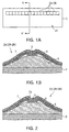
- Fig 1 is a schematic plan view and cross-sectional view
used for explaining the structure of a thermal head;
- Fig. 2 is a cross-sectional view illustrating the thermal
head of Fig. 1 having a protective film suffering a flaw;
- Fig. 3 is a cross-sectional view illustrating the thermal
head of Fig. 1 having a protective film suffering thunderbolt;
- Fig. 4 is a graph illustrating the relation between the
resistance value of a heat generation resistive element and the
time;
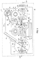
- Fig. 5 is a schematic lateral view illustrating the
structure of a card printer according to an embodiment;
- Fig. 6 is a schematic view used for explaining an ink
ribbon;
- Fig. 7 is a block diagram illustrating the circuit
configuration of a color image printing part;
- Fig. 8 is a block diagram illustrating the internal
configuration of a thermal head;
- Fig. 9 is a block diagram illustrating the configuration of
a head diagnosis part illustrated in Fig. 7;
- Fig. 10 is a block diagram illustrating in detail the
configuration of the head diagnosis part of Fig. 9;
- Fig. 11 is a graph illustrating the relation between the
resistance value of a heat generation resistive element and a
voltage based on differential voltage data;
- Fig. 12 is a flow chart used for explaining a head
diagnosis processing procedure; and
- Fig. 13 is a flow chart used for explaining a head
diagnosis processing procedure.
-
DETAILED DESCRIPTION OF THE EMBODIMENT
-
Preferred embodiments of this invention will be described
with reference to the accompanying drawings:
-
Generally, as illustrated in Fig. 1A, a thermal head 1 has
a plurality of heat generators 2A to 2N (N is a predetermined
number) arranged in line on a head surface 1A perpendicularly to
the traveling direction of a printing paper (not shown). Each of
the heat generators 2A to 2N has a heat generation resistive
element 5 on a protrusion of a glass layer 4 laminated on a ceramic
substrate 3 as illustrated in a cross-sectional view taken along a
line A-A' across the head surface 1A in Fig. 1B. The heat
generation resistive element 5, together with electrodes 6 formed
at one end and the other end thereof, is overlaid by a protective
film 7 made of a glass material.
-
If relatively hard dust or the like gets in between the
head surface 1A of the thermal head 1 and a platen (not shown) to
damage the heat generators 2A to 2N on the head surface 1A, the
protective film 7 of the heat generators 2A to 2N corresponding to
the damaged portion is likely to suffer a flaw 7A as illustrated in
Fig. 2. In this event, since stress concentrates on the flaw 7A in
the protective film 7, the heat generation resistive element 5
changes its resistance value. When any of the heat generators 2A
to 2N is gravely damaged, an associated heat generation resistive
element 5 is opened to break a current flow, resulting in a white
line drawn on a printing paper along its traveling direction.
-
On the other hand, if static electricity is generated on
the head surface 1A of the thermal head 1 during a printing
operation to cause a thunderbolt, a pinhole 7B is likely to be
formed through the protective film 7 of the heat generators 2A to
2N, which was stuck by the thunderbolt, as illustrated in Fig. 3.
In this event, since moisture, ions or the like can get in or out
through the pinhole 7B of the protective film 7, the heat
generation resistive element 5 changes its resistance value. If a
stronger thunderbolt is generated, a current always flows into the
heat generation resistive element 5, resulting in a black line
drawn on a printing paper along its traveling direction.
-
Here, Fig. 4 illustrates the relation between the
resistance value of the heat generation resistive element 5 and the
time change. In Fig. 4, a characteristic curve F1 of the heat
generation resistive element 5 has a characteristic in which the
resistance value of the heat generation resistive element 5 is R0
at time T0, once decreases over time, and then gradually increases.
-
Actually, if any of the heat generators 2A to 2N flaws at
time T1 to open its heat generation resistive element 5, the
resistance value of the heat generation resistive element 5
slightly increases and causes a slightly upward shift of the
characteristic curve F1, resulting in a characteristic curve F1A.
On the other hand, if a thunderbolt is generated in the heat
generators 2A to 2N at time T1 to short-circuit a heat generation
resistive element 5, the resistance value of the heat generation
resistive element 5 slightly lowers and causes a slightly downward
shift of the characteristic curve F1, resulting in a characteristic
curve F1B.
-
It is therefore possible to judge whether or not a heat
generation resistive element 5 exhibits an abnormal electrification
state by detecting an increasing or decreasing resistance value of
the heat generation resistive element 5 to consequently diagnose
the condition of the thermal head 1.
(2) General Configuration of Card Printer
-
In Fig. 5, a card printer, to which the present invention
is applied, is generally designated by reference numeral 10. A
card material 13 inserted into the card printer from a card
insertion slot 11A of a housing 11 through cleaning rollers 12A,
12B is carried by the card carrier 14 along a carrying path CR.
-
The card material 13 employed in this embodiment conforms
to the so-called International Organization for Standardization
(ISO) standard. Specifically, the card material 13 has a magnetic
stripe formed on one side along a longitudinal edge, and an
Integrated Circuit (IC) memory embedded in the other side at a
predetermined position near a front end of the card material 13.
-
The card carrier 14 is composed of first and second
carrying sections 14A, 14B disposed on front and back sides of a
platen 15 along the carrying path CR. The first and second
carrying sections 14A, 14B are provided with four pairs of carrying
rollers 16A to 19A and 16B to 19B, respectively, which are mounted
on axes for any rotation along the carrying path CR at
predetermined intervals.
-
The upper carrying rollers 16A to 19A are rotated in the
same direction in association with each other according to the
rotation of a driving motor (not shown), while the lower carrying
rollers 16B to 19B are kept in contact with the corresponding upper
carrying rollers 16A to 19A, so that the lower carrying rollers 16B
to 19B are rotated in the direction opposite to the rotation of the
upper carrying rollers 16A to 19A. With the structure as mentioned,
the card material 13, inserted between the upper and lower carrying
rollers 16A to 19A and 16B to 19B, is carried forward or backward
along the carrying path CR in accordance with the rotation of the
upper carrying rollers 16A to 19A.
-
A color image printing part 20 is disposed at a
predetermined position opposing the platen 15 above the card
carrier 14. In the color image printing part 20, a head holding
mechanism 22 including a head part 21 is extended in a direction in
which a thermal head 23 supported at a leading end of the head part
21 is pressed against the platen 15, and is retracted in a
direction in which the thermal head 23 is brought away from the
platen 15.
-
Actually, the head holding mechanism 22 is constructed of a
cam 25 which rotates on a driving shaft 24 of a head motor (not
shown), and a link mechanism engaged with the cam 25 and including
a shifter member 28, a connecting member 29 and a supporting member
30 with a rotating shafts 26, 27 as fixed links.
-
Thus, in this head holding mechanism 22, the link mechanism
26 to 30 engaged with the cam 25 is extended in response to the
driving of the head motor in a printing mode in order to press the
thermal head 23 against the platen 15. After terminating the
printing mode, the link mechanism 26 to 30 engaged with the cam 25
is retracted in response to the driving of head motor in order to
bring the thermal head 23 away from the platen 15.
-
In an image printing mode, the color image printing part 20
drives the head holding mechanism 22 to press the thermal head 23
against the platen 15 with a roll-shaped ink ribbon 33, supported
by a supply reel 31 and a wind-up reel 32, and a card material 13
positioned on the platen 15 interposed in between. Subsequently,
the thermal head 23 is heated in this state based on a
predetermined image printing signal to thermal-transfer the ink on
the ink ribbon 33 onto one side of the card material 13.
-
In this case, the roll-shaped ink ribbon 33 is accommodated
in a ribbon cassette 34. The ribbon cassette 34 is loaded capable
of being removed between the color image printing part 20 and the
platen 15 through a cassette insertion slot (not shown) formed on a
side wall of the housing 11.
-
The ink ribbon 33 includes color pigments of yellow Y,
magenta M, cyan C and black K, each coated over at a predetermined
length thereon as a pigment for one piece of the card material 13,
followed by a film-like sheet L, as illustrated in Fig. 6. Further,
a predetermined mark (not shown) is impressed at the head position
for each page of the ink ribbon 33 in order that the head position
of the ink ribbon 33 can be located by detecting the mark by an
optical sensor (not shown) disposed on a running path of the ink
ribbon 33.
-
The supply real 31 is provided with a torque limiter (not
shown) for applying a predetermined torque during rotation, so that
the ink ribbon 33 is always applied with a back tension. Further,
an optical sensor (not shown) is disposed near the supply real 31
for detecting the diameter of the rolled ink ribbon 33. And by
detecting the tension of the ink ribbon 33, the winding state of
the wind-up reel 32 can be controlled.
-
Below the carrying path CR in the second carrier 14B, a
magnetic recording/reproducing part 40 is disposed. A magnetic
head 41 is exposed on the carrying path CR so as to be positioned
side by side with the lower carrying roller 18B and contacted the
upper carrying roller 18A only during recording and reproduction.
And the magnetic head 41 is concealed below the carrying path CR
other than during recording and reproduction.
-
Thus, the magnetic recording/reproducing part 40 records
information based on a predetermined recording signal on magnetic
stripes (not shown) formed on one side of the card material 13,
with the magnetic head 41 exposed on the carrying path CR.
Subsequently, the magnetic recording/reproducing part 40 reproduces
the recorded information to judge whether or not any recording
errors are found on the magnetic stripes.
-
Optical sensors 42, 43, 44 of photo-interrupter type are
disposed on front and back sides of the first carrying section 14A
and in front of the second carrying section 14B in order that the
presence or absence of the card material 13 carried along the
carrying path CR is detected.
-
Behind the second carrier 14B and near a card discharge
slot 11B of the housing 11, a rotary carrier 45 is disposed along
the carrying path CR. The rotary carrier 45 has a rotary mechanism
46 supported on a rotating shaft 47 on which it can rotate in a
direction indicated by an arrow r or in the opposite direction.
The rotary mechanism 46 includes a first pair of flipper rollers
48A, 48B and a second pair of flipper rollers 49A, 49B. And each
pair is capable of any rotation keeping a symmetrical position with
the rotation shaft 47 in between.
-
The flipper rollers 48A, 49A on an upper side each rotate
in the same direction in conjunction with the rotation of the
driving motors (not shown). The flipper rollers 48B, 49B on a
lower side are each pressed against the corresponding flipper
rollers 48a, 49A on the upper side, and rotate in the opposite
direction to the rotation of the flipper rollers 48A, 49A. With
the structure as mentioned, the card material 13 inserted between
the first pair of flipper rollers 48A, 48B and/or between the
second pair of flipper rollers 49A, 49B is carried forward or
backward on the carrier path CR according to the rotation of the
flipper rollers 48A, 49A on the upper side.
-
In this way, the rotary carrier 45 holds the card material
13 carried from the second carrying section 14B in the rotary
mechanism 46, and rotates the rotary mechanism 46 together with the
card material 13 held therein over a predetermined angular distance
in the direction indicated by the arrow r or in the opposite
direction as required to position the rotary mechanism 46, so that
the card material 13 is delivered in a predetermined direction
determined by positioning.
-
An IC recording/reproducing part 50 is disposed near the
rotary carrier 45. As the card material 13 delivered from the
rotary carrier 45 is inserted into an insertion slot 50A of the IC
recording/reproducing part 50, each terminal of an IC memory (not
shown) disposed on the other side of the card material 13 is
brought into contact with an interface connector (not shown). As a
result, the IC recording/reproducing part 50 records information
based on a predetermined recording signal, and then reproduces the
recorded information to judge whether or not any recording errors
are found in the IC memory.
-
An unacceptable card tray 51 is disposed near the rotary
carrier 45. A card material 13, which has been judgeded that
recording errors have been found in the magnetic
recording/reproducing part 40 or in the IC recording/reproducing
part 50, is discharged from the rotary carrier 45 through an inlet
slot 51A to the unacceptable card tray 52.
-
Conversely, the rotary carrier 45 delivers a card material
13, which has been determined that no recording errors have been
found in the magnetic recording/reproducing part 40 or in the IC
recording/reproducing part 50, to an external card tray (not shown)
through a card discharge slot 11B of the housing 11.
-
In addition, a first optical sensor 52 and a second optical
sensor 53, both of a photo-interrupter type, are disposed outside
the first pair of flipper rollers 48A, 48B and outside the second
pair of flipper rollers 49A, 49B (i.e., both in the centrifugal
direction of the rotating shaft 47), respectively, for detecting
the presence or absence of the card material 13 sent thereto along
the carrying path CR.
-
For reference, in this card printer 10, the card carrier 14,
the color image printing part 20, the magnetic
recording/reproducing part 40, the rotary carrier 45 and the IC
recording/reproducing part 50 are each driven in predetermined
states in accordance with the control of a CPU 61 which responds to
instructions from a host computer 60 (Fig. 7), later described.
(3) Printing Processing in Color Image Printing Part
-
Fig. 7 illustrates the circuit configuration of the color
image printing part 20. As predetermined image printing data DP is
supplied from a host computer 60 through an interface (I/F) 62 and
a Computer Interface (C/I) driver 63, a memory controller 64 writes
a one-frame portion of the image printing data DCP into
corresponding frame memories 65 to 69 as color image printing data
DPY (yellow Y), DPM (magenta M), DPC (cyan C) and DPK (black K),
corresponding to the respective colors, and laminate data PDL
(film-like sheet L) in accordance with the control of the CPU 61.
-
Next, the memory controller 64 reads the color image
printing data DPY, DPM, DPC, DPK and the laminate data DPL from the
respective frame memories 65 to 69 at predetermined timing in
accordance with the control of the CPU 61. Then the color image
printing data DPY, DPM, DPC are transmitted to color adjustment
parts 70 to 72, respectively, and the color image printing data DPK
and the laminate data DPL are transmitted to respective input
terminals of a selector 73.
-
The color adjustment parts 70 to 72, which are provided
with a color conversion table (not shown) having standard image
printing characteristics for each color, perform color adjustment
for each color in accordance with an adjustment curve before and
after color matching processing, and transmit resulting color image
printing data DPY1, DPM1, DPC1 to a masking part 74.
-
The masking part 74 separates unnecessary data from the
supplied color image printing data DPY1, DPM1, DPC1 and transmits
resulting color image printing data DPY2, DPM2, DPC2 to the other
input terminal of the selector 73.
-
The selector 73 sequentially transmits data selected as
required from the respective color image printing data DPY2, DPM2,
DPC, DPK and the laminate data DPL, supplied thereto, based on the
control of the CPU 61 to a gamma correction part 75. The gamma
correction part 75 performs a color-strength electrification time
conversion with a predetermined heat correction coefficient which
has been set on the basis of the control of the CPU 61, and
supplies a head controller 76 with print image data DT resulting
from the conversion.
-
The head controller 76, which is disposed in the head
holding mechanism 22, converts the print image data DT to a current
signal DI which is then provided to the thermal head 23. As a
result, a plurality of heat generation resistive elements arranged
on a head surface (not shown) of the thermal head 23 are heated in
accordance with the current signal DI. Consequently, the color
image printing part 20 can heat the head surface of the thermal
head 23 based on the image printing data DP, and print a desired
color image in accordance with the image print data DP based on the
heated head on one or the other side of the card material 13.
-
The CPU 61 can move the thermal head 23 in the head part 22
closer to or away from the platen 15 by controlling the driving of
mechanical controller 77 including the aforementioned cam 25 and
the link mechanism 26 to 30, described in Fig. 5. The CPU 61 also
sends control instructions to respective circuits through a bus 78.
-
In addition to the configuration described above, the color
image printing part 20 is provided with a head diagnosis part 80
between the CPU 61 and the thermal head 23. The head diagnosis
part 80 sequentially measures the resistance value of each heat
generation resistive element one by one for a plurality of heat
generators (not shown) disposed on the head surface of the thermal
head 23 in order to permit judgement as to whether or not the
resistance value of each heat generation resistive element is
normal based on the results of the measurements.
-
The CPU 61 first sends a switching signal S1 to the head
diagnosis part 80 to selectively switch the head diagnosis part 80
to a printing mode or a head diagnosis mode. In this event, for
selecting the head diagnosis mode, the head controller 76 sends
electrification setting data DE to the thermal head 23 for
sequentially measuring one by one the resistance value of the heat
generation resistive elements corresponding to the respective heat
generators of the thermal head 23 in accordance with the control of
the CPU 61.
-
As illustrated in Fig. 8, the thermal head 23 has a
plurality of heat generators 23H1 to 23HN (N is for example equal
to 640) on the head surface. The heat generators 23H1 to 23HN are
connected by a latch circuit 90 to a plurality of registers 91R1 to
91RN, which constitute a serial-type shift register.
-
Image printing data DI are orderly stored one by one in the
plurality of registers 91R1 to 91RN in synchronization with a clock
CL inputted thereto. When the image printing data DI have been
stored in all of the registers 91R1 to 91RN, all outputs of the
91R1 to 91RN are applied in parallel to the latch circuit 90.
-
Respective heat generators 23H1 to 23HN are connected to a
common power supply 94 through heat generation resistive elements
93R1 to 93RN which basically comprise transistors 92Q1 to 92QN,
respectively, each of which has a collector connected to a load
resistor. All emitters are connected to a common terminal (not
shown) in the head diagnosis part 80. And bases are connected to
each output stage of the latch circuit 90 through load resistors
95R1 to 95RN, respectively.
-
The latch circuit 90, upon receiving the electrification
setting data DE supplied from the head controller 76, sequentially
electrifies and connects one by one between a heat generator 23HI
(I is an arbitrary number satisfying 1≦I≦N) and a corresponding
register 91RI, thereby sequentially turning on a transistor 92QI in
the heat generator 23HI. This causes a voltage of the power supply
94 to be applied to each heat generator 23HI, and a collector-emitter
current to flow through a corresponding heat generation
resistive element 93RI into the head diagnosis part 80.
-
The head diagnosis part 80 has a configuration based on an
operational amplifier 100, as illustrated in Fig. 9, which has one
input terminal connected to the thermal head 23, to a drain of a
power Metal Oxide Semiconductor (MOS) Field Effect Transistor (FET)
101 and to a load resistor 102R, and the other input terminal is
connected to a reference voltage source 103.
-
A source of the power MOS FET 101, the load resistor 102R
and the reference voltage source 103 are connected to a ground GND.
The power MOS FET 101 is used as a switching circuit which turns on
or off in response to "H" or "L" level of the switching signal S1
supplied from the CPU 61 to the gate thereof.
-
More specifically, in the printing mode, when the CPU 61
supplies the power MOS FET 101 with the switching signal S1 at "H"
level to cause the power MOS FET 101 to turn on, current supplied
from each heat generator 23HI flows into the ground GND as a drain-source
current of the power MOS FET 101. For this reason, the
current supplied from each heat generator 23HI does not flow
through an intermediate connection point P1 between the one input
terminal of the operational amplifier 100 and the load resistor
102R.
-
In the head diagnosis mode, on the other hand, when the CPU
61 supplies the power MOS FET 101 with the switching signal S1 at
"L" level to cause the power MOS FET 101 to turn OFF, the current
supplied from each heat generator 23HI does not flow through the
drain-source of the power MOS FET 101 but flows through the
intermediate connection point P1 into the one input terminal of the
operational amplifier 100 as well as through the load resistor 102R
to the ground GND.
-
Responsively, the operational amplifier 100 calculates the
difference in potential between the one input terminal and the
other input terminal, subsequently converts the differential
voltage to a digital form through an analog-to-digital (A/D)
converter circuit 104, and sends the digital product to the CPU 61
as differential voltage data DVS.
-
The operational amplifier 100 is composed of a differential
amplifier circuit 110 as a basic component, and a current
regulating circuit 111 connected thereto, as illustrated in Fig. 10.
The differential amplifier circuit 110 has a pair of PNP
transistors Q1, Q2, which have their bases connected to the power
supply 94 through a heat generation resistive element 93RI of the
heat generator 23HI and a load resistor 113R which has the same
resistance value as the heat generation resistive element 93RI,
respectively.
-
An intermediate connection point P2 between the base of the
transistor Q2 and the load resistor 113R is connected to an end of
a voltage dividing resistor 114R which has the same resistance
value as the load resistor 102R and has the other end connected to
the ground GND. The reference voltage source 103 mentioned above
in connection with Fig. 9 is actually composed of the resistors
113R, 114R connected in series between the power supply 94 and the
ground GND, and the differential amplifier 110 connected to the
intermediate connection point P2 between the resistors 113R and
114R.
-
The transistor Q1 has a collector connected to the ground
GND, while the transistor Q2 has a collector connected through a
voltage dividing resistor 115R to the ground GND. An intermediate
connection point P3 between the collector of the transistor Q2 and
the resistor 115R is connected to the A/D converter circuit 104.
-
The current regulating circuit 111 has a pair of PNP
transistors Q3, Q4, which have their emitters connected commonly to
the power supply 94 through load resistors 116R, 117R. Bases of
the transistors Q3, Q4 are connected to one end of a capacitor C1,
the other end of which is connected to the power supply 94, and
also connected through a load resistor 118R to the ground GND.
Thus, the current regulating circuit 111 is configured in order
that the same current as that flowing into the transistor Q4 flows
into the transistor Q3.
-
The transistor Q3 has its collector connected through load
resistors 119R, 120R commonly to emitters of the transistors Q1, Q2
in the differential amplifier circuit 110, respectively.
-
In the configuration illustrated in Fig. 10, the power MOS
FET 101 is in OFF state in the head diagnosis mode, wherein a
currents flows into the intermediate connection point P1 from the
power supply 94 through the heat generation resistive element 93RI
of the heat generator part 23HI, thereby causing a potential
difference VI to be generated at the intermediate connection point
P1, as expressed by the following expression (1):
VI = rM (rI + RM) × VM
where a voltage value of the power supply 94 is VH; the resistance
value of the heat generation resistive element 93RI is rI; and the
resistance value of the load resistor 102R is rM.
-
In this event, if the resistance value rI of the heat
generation resistive element 93RI falls within a predetermined set
standard range, the intermediate connection points P1, P2 both have
the same potential difference, so that a differential voltage value
outputted from the differential amplifier circuit 110 through the
intermediate connection point P3 is applied as it is to the A/D
converter circuit 104.
-
Here, if the resistance value rI of the heat generation
resistive element 93RI is higher than the set standard range to
reduce the potential at the intermediate connection point P1, a
current flowing into the base of the transistor Q1 decreases,
causing an emitter-collector current of the transistor Q1 to
decrease. At this point, since a current flowing from the current
regulating circuit 111 is regular, a reduced portion of the
emitter-collector current of the transistor Q1 is added to an
emitter-collector current of the transistor Q2 to increase the same.
As a result, the potential difference at the intermediate
connection point P3 is increased and applied to the A/D converter
circuit 104.
-
On the other hand, if the resistance value rI of the heat
generation resistive element 93RI is lower than the set standard
range to increase the potential at the intermediate connection
point P1, a current flowing into the base of the transistor Q1
increases, causing the emitter-collector current of the transistor
Q1 to increase. At this point, since a current flowing from the
current regulating circuit 111 is regular, the increased emitter-collector
current of the transistor Q1 is subtracted from the
emitter-collector current of the transistor Q2 to reduce the same.
As a result, the potential difference at the intermediate
connection point P3 is reduced and applied to the A/D converter
circuit 104.
-
In this way, when the thermal head 23 is applied with the
electrification setting data DE, a current flows through the heat
generation resistive element 93RI disposed in each heat generator
23HI within the thermal head 23 to generate a drop voltage VI
across the heat generation resistive element 93RI. The head
diagnosis part 80 calculates a difference between the voltage VI
and the voltage VM of the reference voltage source 103 and converts
the calculated difference to a digital form to produce differential
voltage data DVS which is sent to the CPU 61.
-
The CPU 61 also contains a predetermined conversion table
(not shown), such that the resistance value rI of the heat
generation resistive element 93RI corresponding to the differential
voltage data DVS can be retrieved from the conversion table based
on a characteristic curve F2 which represents the resistance value
rI of the heat generation resistive element 93RI in proportion to
the voltage of the differential voltage data DVS, as illustrated in
Fig. 11.
-
Consequently, the CPU 61 sequentially retrieves from the
conversion table the resistance value rI of the heat generation
resistive element 93RI corresponding to the differential voltage
data DVS sequentially supplied from the head diagnosis part 80
based on the differential voltage data DVS, and then stores the
retrieved resistance value rI in a flash memory 81.
-
The flash memory 81 previously stores initial resistance
value (the resistance value measured when they were manufactured)
r0I of all the heat generation resistive elements 93RI, and also
stores the resistance value rI of all the heat generation resistive
elements 93RI measured in the previous head diagnosis mode.
-
Here, if the CPU 61 judges that the resistance value rI of
a heat generation resistive element 93RI corresponding to a voltage
of differential voltage data DVS supplied from the head diagnosis
part 80 is out of a predetermined range with respect to the
characteristic curve F2 illustrated in Fig. 11, the CPU 61 sends a
printing reference signal S2 to the host computer 60 through the
C/I driver 63 and the interface 62 as required (Fig. 7).
-
The host computer 60, upon receipt of the printing
reference signal S2, judges whether or not a heat generator 23HI
within the thermal head 23 exhibiting an abnormal electrification
state actually is used for an image printing area based on image
printing data DP within an image to be printed, and sends a
diagnosis notification signal S3 in accordance with the result of
the judgement to the CPU 61 through the interface and the C/I
driver.
-
In this event, the host computer 60 sends to an error
display part 82 an error signal S4 indicating that the thermal head
23 has failed, when the result of the judgement is negative,
thereby causing the error display part 82 to display on its display
screen that the thermal head 23 has failed.
(4) Processing Procedure for Diagnosing Thermal Head
-
The CPU 61 in the color image printing part 20 executes a
head diagnosis processing procedure RT1 illustrated in Figs. 12, 13
based on the control of the host computer 60, to diagnose whether
or not each of heat generators 23H1 to 23HN, arranged on the
surface of the thermal head 23, exhibits an abnormal
electrification state by sequentially measuring one by one the
resistance value of the heat generation resistive elements 93R1 to
93RN within the respective heat generators 23H1 to 23HN.
-
First, the CPU 61 enters the head diagnosis processing
procedure RT1 illustrated in Fig. 12 from step SP0 in accordance
with the control of the host computer 60, before starting a
printing operation or after ending a printing operation, that is,
when not in the printing mode. At subsequent step SP1, the CPU 61
turns off the power MOS FET 101 to set the head diagnosis mode.
Then, the CPU 61 proceeds to step SP2, where the CPU 61
sequentially electrifies one by one the heat generation resistive
elements 93R1 to 93RN in the plurality of heat generators 23H1 to
23HN of the thermal head 23.
-
Subsequently, the CPU 61 proceeds to step SP3, where for
one of the heat generators 23HI (1≦I≦N), a current flowing into
the intermediate connection point P1 from the power supply 94
through the head generation resistive element 93RI and a current
flowing from the reference voltage source 103 are applied to one
input terminal and the other input terminal, respectively, of the
operational amplifier 100 in the head diagnosis unit 80 illustrated
in Fig. 9, to force the operational amplifier 100 to calculate the
difference between the voltage VI at the intermediate connection
point P1 and the voltage VM of the reference voltage source 103.
Then, the CPU 61 receives the differential voltage.
-
Next, at step SP4, the CPU 61 retrieves the resistance
value rI of the heat generation resistive element 93RI
corresponding to the received differential voltage in accordance
with the predetermined conversion table (not shown) stored therein.
-
At step SP5, the CPU 61 determines whether or not the
retrieved resistance value rI of the heat generation resistive
element 93RI is within a predetermined range with respect to the
characteristic curve F2 in the aforementioned Fig. 11.
-
If a negative result is returned at step SP5, this means
that the heat generation resistive element 93RI is in an open state
or in a short-circuited state, in which case the CPU 61 proceeds to
step SP6, where it further judges whether or not the resistance
value rI is higher than the predetermined range with respect to the
characteristic curve F2.
-
If an affirmative result is returned at step SP6, this
means that the heat generation resistive element 93RI is in a
short-circuited state, in which case the CPU 61 proceeds to step
SP7 (Fig. 13), later described, where it notifies the host computer
60 of the fact that the heat generation resistive element 93RI
exhibits an abnormal electrification state.
-
On the other hand, if a negative result is returned at step
SP6, this means that the heat generation resistive element 93RI is
in an open state, in which case the CPU 61 proceeds to step SP8,
where the CPU 61 forces the host computer 60 to judge whether or
not the heat generation resistive element 93RI is actually a heat
generation resistive element RI of a heat generator 23HI falling
into an image printing area based on image printing data DP within
an image to be printed.
-
If an affirmative result is returned at step SP8, this
means that the heat generator 23HI does affect the contents to be
printed on a card material 13, in which case the CPU 61 proceeds to
step SP7, where it notifies the host computer 60 of the fact that
the heat generation resistive element 93RI exhibits an abnormal
electrification state, as mentioned above.
-
On the other hand, if a negative result is returned at step
SP8, the CPU 61 determines that the heat generation resistive
element 93RI is in a normal electrification state since the
contents to be printed on the card material 13 will not be affected
by the heat generation resistive element 93RI even if it is in an
open state. Then, the CPU 61 proceeds to step SP9 (Fig. 13), later
described.
-
At step SP5, if an affirmative result is returned, this
means that the resistance value of the heat generation resistive
element 93RI retrieved from the conversion table is within the
predetermined range with respect to the characteristic curve F2, in
which case the CPU 61 proceeds to step SP10, where it reads from
the flash memory 81 the resistance value rI' of the heat generation
resistive element 93RI measured in the preceding head diagnosis
mode, and an initial resistance value r0I of the heat generation
resistive element 93RI at the time of manufacturing.
-
Subsequently, at step SP11, the CPU 61 calculates a
changing rate AI of the resistance value rI of the heat generation
resistive element 93RI measured at this time to the resistance
value rI' of the heat generation resistive element 93RI measured at
the preceding time as represented by the following expression (2):
AI = |rI - rI'|rI'
-
Subsequently, the CPU 61 proceeds to step SP12, where it
determines whether or not the difference between the changing rate
AI and a changing rate AI' which is calculated in the preceding
head diagnosis mode is equal to or less than a predetermined value.
If a negative result is returned, this means that it is highly
likely that the heat generation resistive element 93RI falls into
an abnormal electrification state. The CPU 61 proceeds to step
SP13 illustrated in Fig. 13, where it judges whether the changing
rate AI exceeds a predetermined value which is set as an abnormal
changing rate.
-
If a negative result is returned at step SP13, this means
that the difference between the changing rate AI and the previously
calculated changing rate AI' is equal to or more than the
predetermined value and equal to or less than the predetermined
value above which an abnormal changing rate is identified. At this
point, the CPU 61 proceeds to step SP14, where it sets a flag
representative of a warning (hereinafter referred to as the
"warning flag") in the flash memory 81 in order to register that
the heat generation resistive element 93RI is less likely to fall
into an abnormal electrification state at this time.
-
Subsequently, the CPU 61 proceeds to step SP15, where it
judges whether or not a warning flag has been set in the flash
memory 81 for the heat generation resistive element 93RI in the
preceding head diagnosis mode.
-
If an affirmative result is returned at step SP15, this
means that the heat generation resistive element 93RI has been
likely to fall into an abnormal electrification state not only at
the preceding time but also at the present time. At this point,
the CPU 61 proceeds to step SP7, where it judges in the foregoing
manner that the heat generation resistive element 93RI has been in
an abnormal electrification state, and notifies the host computer
60 of this fact.
-
On the other hand, if a negative result is returned at step
SP15, this means that the heat generation resistive element 93RI
could exhibit for the first time an abnormal electrification state
in the current head diagnosis mode, in which case the CPU 61
proceeds to step SP9.
-
Turning back to step SP12 illustrated in Fig. 12, if an
affirmative result is returned, this means that the difference
between the changing rate AI and a changing rate AI' which is
calculated in the preceding head diagnosis mode of the heat
generation resistive element 93 RI is equal to or less than the
predetermined value, and accordingly the heat generation resistive
element 93RI exhibits a normal electrification state, in which case
the CPU 61 proceeds to step SP16 (Fig. 13), where it overwrites the
current resistance value rI and the changing rate AI of the heat
generation resistive element 93RI in the flash memory 81.
-
Subsequently, even if the changing rate AI is within the
predetermined range, the thermal head 23 is likely to fall into a
fault if the resistance value rI of the heat generation resistive
element 93RI takes a value out of the predetermined range with
respect to the initial resistance r0I. Thus, the CPU 61 proceeds
to step SP17, where it judges whether or not the difference between
the resistance value rI and the initial resistance value r0I is
equal to or less than a predetermined value.
-
If a negative result is returned at step SP17, the CPU 61
proceeds to step SP7, where it notifies the host computer 60 of the
fact that the heat generation resistive element 93RI exhibits an
abnormal electrification state, similarly to the above. As a
result, the host computer 60, upon receipt of the notification from
the CPU 61, displays on the display screen of the error display
part 82 that the thermal head 23 is faulty or likely to fall into a
fault.
-
On the other hand, if an affirmative result is returned at
step SP17, this means that the heat generation resistive element
93RI is in a normal electrification state, in which case the CPU 61
proceeds to step SP9, where it judges whether the heat generation
resistive element 93RI is the last electrified heat generation
resistive element 93RN.
-
If an affirmative result is returned at step SP9, the CPU
61 judges that the diagnosis has been completed for all the heat
generation resistive elements 93R1 to 93RN as to whether or not
they exhibit an abnormal electrification state, and then proceeds
immediately to step SP18 to terminate the head diagnosis processing
procedure RT1.
-
On the other hand, if a negative result is returned at step
SP9, the CPU 61 again returns to step SP3, where it executes the
processing from step SP3 to step SP17 for the next electrified heat
generation resistive element 93RI+1 as described above, and repeats
this processing until an affirmative result is returned at step SP9.
(5) Operation and Effect of Embodiment
-
In the configuration described above, in the color image
printing part 20 in the card printer 10, the heat generation
resistive elements 93R1 to 93RN in the plurality of heat generators
23H1 to 23HN arranged on the surface of the thermal head 23 are
sequentially electrified one by one, and the resistance value of
the heat generation resistive elements 93R1 to 93RN is measured
respectively to determine whether or not each of the heat
generation resistive elements 93RI (1≦I≦N) is open or short-circuited
based on the resistance value rI thereof during the head
diagnosis mode.
-
If the respective heat generation resistive elements 93RI
are not open or short-circuited, then the changing rate AI of the
heat generation resistive element 93RI is calculated on the basis
of the resistance value rI' of the heat generation resistive
element 93RI measured at the preceding time and the resistance
value rI corresponding thereto measured at the current time. It
can be determined on the basis of each changing rate AI whether or
not the associated heat generation resistive element 93RI is
currently in a normal electrification state or is likely to suffer
a fault in future, before actually entering a printing stage.
-
In this event, even if each heat generation resistive
element 93RI is determined to be normal at present, it can be
judged whether or not the thermal head 23 is faulty or is likely to
fall into a fault in accordance of the difference between the
changing rate AI of the heat generation resistive element RI and
the previously calculated changing rate AI' of the heat generation
resistive element 93RI' corresponding thereto.
-
When it is determined as above that the thermal head 23 is
faulty or is likely to fall into a fault, this fact is displayed on
the error display unit 82, thereby allowing the operator to readily
and visually confirm the condition of the thermal head 23 before
entering a printing stage.
-
Even when some heat generation resistive elements 93RX (X
is an arbitrary number) of the plurality of heat generation
resistive elements 93R1 to 93RN are opened, the heat generation
resistive elements 93RX are treated as normal if the heat
generation resistive elements 93RX are not actually heat generation
resistive elements which correspond to an image printing area based
on image printing data DP within an image to be printed, because
they do not affect the contents printed on a card material 13. In
this way, when the heat generation resistive elements 93RX only are
opened among the plurality of heat generation resistive elements
93R1 to 93RN, the thermal head 23 need not be replaced with a new
one, thereby making it possible to further improve the use
efficiency of the thermal head 23.
-
According to the foregoing configuration, in the color
image printing part 20 of the card printer 10, the heat generation
resistive elements 93R1 to 93RN within the plurality of heat
generators 23H1 to 23HN arranged on the surface of the thermal head
23 are sequentially electrified one by one before starting a
printing operation or after ending a printing operation. Then, the
changing rate AI is calculated on the basis of the previously
measured resistance value rI' of each heat generation resistive
element 93RI (1≦I≦N) and the corresponding resistance value rI
measured at the current time. Then, a electrification state of the
corresponding heat generation resistive element 93RI is determined
on the based on the changing rate AI, thereby making it possible to
previously judge the condition of the thermal head 23 before
entering an actual printing stage. Consequently, printing errors
can be efficiently prevented.
(5) Other Embodiments
-
In the foregoing embodiment, when a heat generation
resistive element 93RI exhibits an abnormal electrification state,
the CPU 61 judges the host computer 60 of this fact as the
predetermined error processing, so that the host computer 60 forces
the error display part 82 to display on its display screen that the
thermal head 23 is faulty or is likely to fall into a fault. The
present invention is not limited thereto. Alternatively, when a
heat generation resistive element 93RI exhibits an abnormal
electrification state, the CPU 61 can bring the color image
printing part 20 into a printing stop state instead of or in
addition to notifying the host computer 60 of the fact. In this
case, even if the color image printing part 20 is switched to a
printing mode, it is possible to obviate printing errors on a card
material 13 since the color image printing part 20 is in the
printing stop state.
-
Also, in the foregoing embodiment, when a certain heat
generation resistive element 93RX (X is an arbitrary number) among
the plurality of heat generation resistive elements 93R1 to 93RN is
opened, the CPU 61 sends a printing reference signal S2 to the host
computer 60 so that the host computer 60 judges whether or not the
heat generation resistive element 93RX is actually a heat
generation resistive element which corresponds to an image printing
area based on image printing data DP within an image to be printed.
The present invention, however, is not limited thereto.
Alternatively, the color image printing part 20 illustrated in Fig.
7 can be provided therein with a frame memory (not shown) for
storing an image based on the image printing data DP so that the
CPU 61 makes the above-mentioned determination based on the image
printing data DP read from the frame memory, without intervention
of the host computer 60.
-
Further, in the foregoing embodiment, when the resistance
value of each heat generation resistive element 93R1 to 93RN are
measured, the CPU 61 uses a predetermined conversion table to
retrieve the resistance value of each heat generation resistive
element 93RI (1≦I≦N) corresponding to differential voltage data
DVS supplied from the head diagnosis part 80. The present
invention, however, is not limited thereto. Alternatively, the CPU
61 does inverse calculating differential voltage data DVS outputted
from the head diagnosis part 30 to derive the resistance value of
each heat generation resistive element 93RI. In essence, a wide
variety of other configurations can be applied as measuring means
as long as it can measure the resistance value of each electrified
heat generation resistive element 93RI.
-
Further, in the foregoing embodiment, the CPU 61, serving
as calculation means, calculates the change rate AI for the
resistance value of each heat generation resistive element 93RI
based on the resistance value rI' of each heat generation resistive
element 93RI previously measured in the head diagnosis part 80 and
the resistance value rI of each heat generation resistive element
93RI measured at this time. The present invention, however, is not
limited thereto. Alternatively, a wide variety of other
configurations can be applied as the calculating means.
-
Further, in the foregoing embodiment, the CPU 61, serving
as diagnosis means, relies on the change rate AI for the resistance
value rI of each heat generation resistive element 93RI to jugde a
electrification state of the corresponding heat generation
resistive element 93RI, and with the result of the judgement judges
the condition of the thermal head 23 in accordance. The present
invention, however, is not limited thereto. In essence, the host
computer 60 can be used as the diagnosis means, or a wide variety
of other configurations can be applied as the diagnosis means, as
long as it can readily judge, before actually entering a printing
stage, whether or not each heat generation resistive element 93RI
is currently in a normal electrification state, or whether or not a
fault is currently occurring, or whether or not a fault is likely
to occur in future.
-
Further, in the foregoing embodiment, the flash memory 81
is used as storage means for storing the resistance value rI of
each heat generation resistive element 93RI measured in the head
diagnosis part 80. The present invention, however, is not limited
thereto, but a variety of configurations can be applied including,
for example, electrically erasable programmable read only memory
(EEPROM), static random access memory (static RAM), or the like.
-
Further, while in the foregoing embodiment, the card
material 13 in accordance with the ISO standard is used as a
printing medium, the present invention is not limited thereto.
Alternatively, a card material in accordance with Japan Industrial
Standard (JIS) can be used. Further alternatively, the present
invention can also be applied to a variety of card materials, which
do not have an IC card and/or magnetic stripes.
-
According to the present invention as described above, a
head diagnosis apparatus for diagnosing the condition of a thermal
head comprises: measuring means for measuring respectively the
resistance value of a plurality of heat generation resistive
elements arranged on a head surface of the thermal head; storage
means for storing the resistance value of each of the heat
generation resistive elements measured by the measuring means;
calculating means for calculating a change amount of the resistance
value of each heat generation resistive element based on the
resistance value of each heat generation resistive element measured
in the past, stored in the storage means, and the resistance value
of each heat generation resistive element measured by the measuring
means; and diagnosis means for judging a electrification state of
each heat generation resistive elements based on the calculation
result of the calculating means to diagnose the condition of the
thermal head in accordance with the judgement result; thereby
making it possible to diagnose the condition of the thermal head
before entering a printing stage. Consequently, it is possible to
realize a head diagnosis apparatus which is capable of efficiently
preventing printing errors.
-
Also, in the present invention, a thermal head diagnosis
method for diagnosing the condition of a thermal head first
measures respectively the resistance value of a plurality of heat
generation resistive elements arranged on a head surface of the
thermal head, and then calculates a change amount of the resistance
value of each heat generation resistive element based on the
resistance value of each heat generation resistive element measured
in the past, and the resistance value of each heat generation
resistive elements measured at the current time to determine a
electrification state of each heat generation resistive element
based on the calculation result for diagnosing the condition of the
thermal head in accordance with the judgement result, thereby
making it possible to diagnose the condition of the thermal head
before entering a printing stage. Consequently, it is possible to
realize a head diagnosis method which is capable of efficiently
preventing printing errors.
-
While there has been described in connection with the
preferred embodiments of the invention, it will be obvious to those
skilled in the art that various changes and modifications may be
aimed, therefore, to cover in the appended claims all such changes
and modifications as fall within the true spirit and scope of the
invention.