EP0982007A2 - Spinal column retainer - Google Patents
Spinal column retainer Download PDFInfo
- Publication number
- EP0982007A2 EP0982007A2 EP99306776A EP99306776A EP0982007A2 EP 0982007 A2 EP0982007 A2 EP 0982007A2 EP 99306776 A EP99306776 A EP 99306776A EP 99306776 A EP99306776 A EP 99306776A EP 0982007 A2 EP0982007 A2 EP 0982007A2
- Authority
- EP
- European Patent Office
- Prior art keywords
- end portion
- passage
- spinal column
- block
- rod
- Prior art date
- Legal status (The legal status is an assumption and is not a legal conclusion. Google has not performed a legal analysis and makes no representation as to the accuracy of the status listed.)
- Granted
Links
Images


Classifications
-
- A—HUMAN NECESSITIES
- A61—MEDICAL OR VETERINARY SCIENCE; HYGIENE
- A61B—DIAGNOSIS; SURGERY; IDENTIFICATION
- A61B17/00—Surgical instruments, devices or methods, e.g. tourniquets
- A61B17/56—Surgical instruments or methods for treatment of bones or joints; Devices specially adapted therefor
- A61B17/58—Surgical instruments or methods for treatment of bones or joints; Devices specially adapted therefor for osteosynthesis, e.g. bone plates, screws, setting implements or the like
- A61B17/68—Internal fixation devices, including fasteners and spinal fixators, even if a part thereof projects from the skin
- A61B17/70—Spinal positioners or stabilisers ; Bone stabilisers comprising fluid filler in an implant
- A61B17/7001—Screws or hooks combined with longitudinal elements which do not contact vertebrae
- A61B17/7041—Screws or hooks combined with longitudinal elements which do not contact vertebrae with single longitudinal rod offset laterally from single row of screws or hooks
Definitions
- the present invention relates to an apparatus for retaining portions of a spinal column, such as vertebrae, in a desired spatial relationship. Specifically, the present invention relates to retainers of the type disclosed in U.S. Patent No. 5,741,255, issued April 21, 1998, and in the prior art references cited therein, all of which are incorporated herein by reference.
- the present invention provides an apparatus for retaining portions of a spinal column in a desired spatial relationship.
- the apparatus generally includes a threaded fastener which engages a portion of the spinal column and a longitudinal member or rod which is positioned along the spinal column at a location offset from the fastener.
- An angular member is connected between the fastener and the rod and extends for a first distance in a direction away from the rod and for a second distance in a direction at an angle relative to the first direction.
- a retainer assembly is connected to the rod and the angular member and retains the rod and angular member against movement relative to the retainer assembly.
- the retainer assembly includes a retainer block into which the rodand the angular member extend.
- the retainer assembly is effective to hold the rod and the angular member against movement relative to the block due to force transmitted between the rod and the angular member.
- the above-described force is transmitted between the rod and the angular member by pressing them against one another using an engagement member which, in one embodiment is a set screw.
- the angular member may be provided with retaining surfaces which are engaged by mating surfaces on the block.
- the retaining surfaces and the mating surfaces cooperate to prevent rotational movement of the angular member about a central axis extending through the end portion of the angular member held by the block.
- the angular member may be formed to bend at a right angle between the block and the fastener.
- a section of the angular member extends in a first direction parallel to the rod when the retaining surfaces and mating surfaces are engaged.
- a section of the angular member extends in a direction opposite the first direction when the retaining surfaces and mating surfaces are engaged.
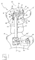
- Figure 1 is a dorsal view of a portion of a spinal column with a spinal column retainer according to the present invention to maintain a desired spatial relationship between vertebrae of the spinal column.
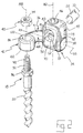
- Figure 2 is a fragmentary, exploded, perspective view of a spinal column retainer according to the present invention.
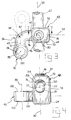
- Figure 3 is a fragmentary top plan view of components of a spinal column retainer according to the present invention.
- Figure 4 is a side elevational view of the apparatus of Figure 3.
- Figure 5 is a fragmentary perspective view of an alternate embodiment of a component of the present invention.
- Figure 6 is another side elevational view of the apparatus of Figure 3.
- Figure 7 is a fragmentary sectional view taken substantially along lines 7-7 of Figure 3.
- FIG. 1 A portion of a human spinal column 10 to which spinal column retainer 12 is attached is illustrated in Figure 1.
- Spinal column retainer 12 positions vertebrae 14, 16 in a desired spatial relationship relative to one another.
- Spinal column retainer 12 includes fasteners 18 made of a biocompatible material, such as stainless steel. As described in greater detail below, fasteners 18 include first threaded portions 20 (Fig. 2) which engage vertebrae 14, 16 to fixedly mount the fasteners to the vertebrae. It should be understood that multiple fasteners 18 may be secured to each vertebrae 14, 16 where multiple spinal column retainers 12 are used. Although Figure 1 shows spinal column retainer 12 configured to space two vertebrae 14, 16 relative to one another, it should be understood that many more vertebrae may be retained in spatial relationship to one another by simply increasing the length of the rod 22 extending along spinal column 10 and attaching additional connector assemblies 30 between rod 22 and the additional vertebrae.
- Rod 22 is made of a biocompatible material, such as stainless steel. As indicated above, rod 22 has a length sufficient to enable the rod to span at least two vertebrae 14, 16. The required length of rod 22 depends upon the condition to be treated and the number of vertebrae to be held in a desired spatial relationship relative to one another. Rod 22 may be bent as desired, typically to establish a desired curvature of spinal column 10 in all or any of three possible anatomic planes.
- FIG 1 shows two types of connector assemblies (30 and 30) for interconnecting rod 22 and fasteners 18.
- the lower connector assembly 30 is of the kind described and shown in U.S. Patent No. 5,741,255.
- connector assembly 30 includes a transverse member 32 which extends between fastener 18 and rod 22 in perpendicular relationship to a longitudinal axis 33 of rod 22.
- the connector assembly 30 of the present invention (the upper connector assembly shown in Figure 1) generally includes a retainer assembly 34 which is mounted on rod 22, and an angular member 36 which extends between fastener 18 and retainer assembly 34.
- Retainer assembly 34 fixes the position of a generally cylindrical inner end portion 38 of angular member 36 relative to retainer assembly 34.
- a clamp assembly 40 fixedly connects an outer end portion 42 of the angular member 36 to fastener 18.
- a connecting portion 44 forms a right angle bend between inner end portion 38 and outer end portion 42 of angular member 36.
- retainer assembly 34 includes a set screw 46 and a generally rectangular retainer block 48 into which angular member 36 and rod 22 extend.
- Block 48 has a rod passage 50 which receives rod 22.
- Rod 22 is shown having a substantially circular cross-section; however, rods having various other cross-sections, such as hexagonal or oval cross-sections, could be used with corresponding modifications to rod passage 50.
- Block 48 also includes a transverse passage 52 which receives inner end portion 38 of angular member 36 and communicates with rod passage 50. As best shown in Figure 6, transverse passage 52 includes a plurality of mating surfaces 54 which engage similarly shaped retaining surfaces or teeth 56 that project radially outwardly from inner end portion 38 of angular member 36.
- Meshing engagement between mating surfaces 54 on block 48 and teeth 56 on inner end portion 38 prevents rotational movement of angular member 36 about a longitudinal central axis 58 of inner end portion 38.
- mating surfaces of various shapes may be formed in transverse passage 52 to receive similarly shaped retaining surfaces formed on block 48.
- the triangular teeth shown in Figure 6 may be replaced with rectangular ridges and mating channels or curved protrusions and mating grooves.
- Inner end portion 38 of angular member 36 further includes an annular lip 64 and a circumferential groove 66 formed, for example, by a swaging operation.
- Annular lip 64 is formed such that its outer diameter is larger than an inner diameter of transverse passage 52 (Fig. 6). Accordingly, angular member 36 is retained within retainer assembly 34 even when rod 22 is removed or raised upwardly within rod passage 50.
- one end of transverse passage 52 includes a beveled edge 68 (Fig. 7) which permits partial recess of annular lip 64 within transverse passage 52.
- block 48 has a pair of parallel, flat side surfaces 70, 72.
- Rod passage 50 extends between and is perpendicular to side surfaces 70, 72.
- Block 48 also includes a pair of parallel side surfaces 76, 78 which extend perpendicular to side surfaces 70, 72 (Fig. 3).
- Transverse passage 52 has a straight longitudinal central axis which extends between and is perpendicular to side surfaces 76, 78.
- Rod passage 50 is formed by a pair of circular openings 81, 83 having centers which are offset along an axis 80 (Figs. 2, 4, and 7) of block 48.
- rod passage 50 has a generally oval cross-sectional configuration.
- axis 80 is substantially centered between sides 70, 72, but is closer to side 76 than side 78 of block 48.
- Circular openings 81, 83 which form rod passage 50 are sized such that rod 22 can move between the upper and lower portion of rod passage 50 when set screw 46 is backed out of set screw passage 60.
- block 48 may be positioned along the length of rod 22.
- upper circular opening 83 is larger than the diameter of rod 22 so that rod 22 can move freely within opening 83.
- Lower circular opening 81 of rod passage 50 has a diameter which is smaller than the diameter of rod 22.
- transverse passage 52 like rod passage 50, has a generally oval cross-section which is elongated in the direction of axis 80 of block 48.
- the oval configuration of transverse passage 52 enables movement of inner end portion 38 of angular member 36 upwardly and downwardly along central axis 80 when set screw 46 is backed out of set screw passage 60.
- the orientation of angular member 36 relative to block 48 may be adjusted by moving end portion 38 upwardly within transverse passage 52 to space teeth 56 from mating surfaces 54 so that inner end portion 38 may be rotated within transverse passage 52 about axis 58 to a desired position relative to block 48 and rod 22 (an example position is shown in dotted lines in Figure 6).
- inner end portion 38 is moved downwardly (by set screw 46 and rod 22) so that teeth 56 engage mating surfaces 54 of block 48, thereby preventing further rotation of angular member 36.
- Transverse passage 52 and rod passage 50 form an intersection 82 (Fig. 7) in a central portion of block 48. Accordingly, a portion of transverse passage 52 extends into rod passage 50.
- rod passage 50 has a central axis which is perpendicular to the central axis of transverse passage 52. In such an embodiment, when spinal column retainer 10 is assembled, axis 58 of inner end portion 38 is perpendicular to longitudinal axis 33 of rod 22 (Fig. 3). It should be understood, however, that transverse passage 52 and rod passage 50 could be formed at an acute angle relative to one another. In such a configuration, inner end portion 38 of angular member 36 would extend from block 48 at an acute angle relative to axis 33 of rod 22.
- Mating surfaces 54 of block 48 are disposed on a side of transverse passage 52 opposite from intersection 82. Mating surfaces 54 extend between side walls 76 and 78 of block 48, parallel to central axis 58 of inner end portion 38. Mating surfaces 54 are formed along an arc of transverse passage 52 and extend approximately 30 degrees on each side of axis 80 of block 48. Accordingly, mating surfaces 54 have a total arcuate extent of approximately 60 degrees.
- each of teeth 56 on inner end portion 38 has a longitudinal axis which extends parallel to central axis 58 of inner end portion 38.
- Teeth 56 have an arcuate extent of approximately 120° about the lower outer surface of inner end portion 38.
- Teeth 56 may, of course, be formed such that they cover more or less than 120° of the outer surface of inner end portion 38. Since the arcuate extent of teeth 56 on inner end portion 38 is greater than the arcuate extent of mating surfaces 54 of block 48, teeth 56 can meshingly engage mating surfaces 54 when angular member 36 is in any one of a plurality of rotational orientations about axis 58 relative to block 48, as described above.
- angular member 36 may be provided in a "right” configuration or a “left” configuration.
- a "right” configuration angular member 36 is shown in the figures. As viewed in Figure 1, angular member 36 extends to the right of block 48 (away from side 76 of block 48) and upwardly, away from side 72 of block 48. As should be apparent from the foregoing, the entire connector assembly 30 could be removed from rod 22, rotated 180°, and reinstalled on rod 22 (Fig. 3) such that angular member 36 extends to the left of block 48 (away from side 76) and downwardly, away from side 72.
- a "left" configuration angular member includes an inner end portion 38 identical to that shown in the figures, but extends away from side 76 of block 48 and upwardly, away from side 70 when block 48 is fastened to rod 22 in the orientation shown in Figure 3.
- a universal angular member 36 could readily be made by, for example, forming groove 62 around the entire circumference of inner end portion 38 and forming teeth 56 on the remainder of the surface of inner end portion 38 not occupied by groove 62. Although the meshing surface area between teeth 56 and mating surfaces 54 would be reduced, such a retainer member 36 could be adjusted to any one of a plurality of angular orientations within a 360° range of adjustment about axis 58. Alternatively, the arcuate extent of teeth 56 could be reduced from 360° and the arcuate extent of mating surfaces 54 could be increased such that a sufficient number of teeth 56 engage a sufficient number of mating surfaces 54 at any one of a plurality of angular orientations within a 360 range of adjustment about axis 58.
- outer end portion 42 of angular member 36 is generally cylindrical in shape and includes a bore 86.
- Bore 86 has a central axis 88 which is perpendicular to central axis 58 of inner end portion 38 (Fig. 2).
- Fastener 18 is received by bore 86.
- central axis 88 of bore 86 may be coincident with a central axis of fastener 18.
- fastener 18 may extend in a direction perpendicular to central axis 58 of inner end portion 38.
- central axis 88 of bore 86 is offset a distance from central axis 58 and a distance from axis 33 of rod 22.
- a clamp assembly 40 is formed by a threaded outer end portion 92 of fastener 18, an internally threaded nut 94, a hexagonal shoulder 96 formed on fastener 18, and a hexagonal outer end portion 98.
- nut 94 may be firmly tightened onto threaded portion 92 of fastener 18 without transmitting force to threaded portion 20 of fastener 18.
- nut 94 When nut 94 is tightened, it engages the upper end surface 100 of outer end portion 42, and shoulder 96 engages the lower end surface 102 of outer end portion 42. Consequently, outer end portion 42 is held fixed relative to fastener 18 by clamp assembly 40.
- Figure 5 shows an alternate embodiment of outer end portion 42 of angular member 36 (designated 42 ).
- Outer end portion 42 includes a slot 86 instead of bore 86.
- Slot 86 is, in this embodiment, elongated in a direction substantially perpendicular to central axis 58 of inner end portion 38 and has a central axis 88 which is substantially perpendicular to axis 58.
- Outer end portion 42 otherwise cooperates with fastener 18 in the manner described above.
- the elongated configuration of slot 86 permits adjustment of the distance between fastener 18 and axis 58.
- Connecting portion 44 of angular member 36 extends between inner end portion 38 and outer end portion 42.
- Connecting portion includes a first section 45 which extends from inner end portion 38, a second section 47 which extends from first section 45, and a third section 49 which extends between second section 47 and outer end portion 42.
- connecting portion 44 is tubular or bar-shaped and first, second, and third portions 45, 47, 49 and substantially planar.
- First section 45 extends away from block 48 and is centered on axis 58 (Fig. 3).
- Second section 47 forms an angular bend or elbow away from axis 58 In the embodiment illustrated, the angular bend of second section 47 is 90°.
- the angular bend could provide a different angle relative to axis 58, such as a 45° angle.
- Third section 49 extends along an axis 51 at the angle relative to axis 58 established by second section 47, and connects to outer end portion 42. It should be understood that outer end portion 42 need not be planar relative to connecting portion 44, but rather may extend at an angle relative to a plane intersecting first, second, and third sections 45, 47, 49 of connecting portion 44.
- the direction of the angular bend of second section 47 determines whether angular member 36 is a "right" or "left” configuration angular member.
- the angular bend provided by connecting portion 44 permits attachment of connector assembly 30 to a vertebra having a portion 16 which would otherwise interfere with a laterally extending transverse member 32 of a connector assembly 30 (the lower connector assembly). Additionally, where multiple spinal column retainers 12 are used on a single spinal column 10, interference between adjacent connector assemblies 30 may be avoided by the offset location of fastener 18 provided by the angular bend of connecting portion 44.
Abstract
Description
- The present invention relates to an apparatus for retaining portions of a spinal column, such as vertebrae, in a desired spatial relationship. Specifically, the present invention relates to retainers of the type disclosed in U.S. Patent No. 5,741,255, issued April 21, 1998, and in the prior art references cited therein, all of which are incorporated herein by reference.
- The present invention provides an apparatus for retaining portions of a spinal column in a desired spatial relationship. The apparatus generally includes a threaded fastener which engages a portion of the spinal column and a longitudinal member or rod which is positioned along the spinal column at a location offset from the fastener. An angular member is connected between the fastener and the rod and extends for a first distance in a direction away from the rod and for a second distance in a direction at an angle relative to the first direction.
- A retainer assembly is connected to the rod and the angular member and retains the rod and angular member against movement relative to the retainer assembly. The retainer assembly includes a retainer block into which the rodand the angular member extend. The retainer assembly is effective to hold the rod and the angular member against movement relative to the block due to force transmitted between the rod and the angular member. In one embodiment of the invention, the above-described force is transmitted between the rod and the angular member by pressing them against one another using an engagement member which, in one embodiment is a set screw.
- The angular member may be provided with retaining surfaces which are engaged by mating surfaces on the block. The retaining surfaces and the mating surfaces cooperate to prevent rotational movement of the angular member about a central axis extending through the end portion of the angular member held by the block. The angular member may be formed to bend at a right angle between the block and the fastener. In one embodiment of the invention, a section of the angular member extends in a first direction parallel to the rod when the retaining surfaces and mating surfaces are engaged. In an alternate embodiment, a section of the angular member extends in a direction opposite the first direction when the retaining surfaces and mating surfaces are engaged.
- The foregoing and other features of the invention will become more apparent and the invention will be better understood upon consideration of the following description taken in conjunction with the accompanying drawings, wherein:
- Figure 1 is a dorsal view of a portion of a spinal column with a spinal column retainer according to the present invention to maintain a desired spatial relationship between vertebrae of the spinal column.
- Figure 2 is a fragmentary, exploded, perspective view of a spinal column retainer according to the present invention.
- Figure 3 is a fragmentary top plan view of components of a spinal column retainer according to the present invention.
- Figure 4 is a side elevational view of the apparatus of Figure 3.
- Figure 5 is a fragmentary perspective view of an alternate embodiment of a component of the present invention.
- Figure 6 is another side elevational view of the apparatus of Figure 3.
- Figure 7 is a fragmentary sectional view taken substantially along lines 7-7 of Figure 3.
- A portion of a human
spinal column 10 to whichspinal column retainer 12 is attached is illustrated in Figure 1.Spinal column retainer 12positions vertebrae -
Spinal column retainer 12 includesfasteners 18 made of a biocompatible material, such as stainless steel. As described in greater detail below,fasteners 18 include first threaded portions 20 (Fig. 2) which engagevertebrae multiple fasteners 18 may be secured to eachvertebrae spinal column retainers 12 are used. Although Figure 1 showsspinal column retainer 12 configured to space twovertebrae rod 22 extending alongspinal column 10 and attaching additional connector assemblies 30 betweenrod 22 and the additional vertebrae. -
Rod 22 is made of a biocompatible material, such as stainless steel. As indicated above,rod 22 has a length sufficient to enable the rod to span at least twovertebrae rod 22 depends upon the condition to be treated and the number of vertebrae to be held in a desired spatial relationship relative to one another.Rod 22 may be bent as desired, typically to establish a desired curvature ofspinal column 10 in all or any of three possible anatomic planes. - Figure 1 shows two types of connector assemblies (30 and 30) for interconnecting
rod 22 andfasteners 18. Thelower connector assembly 30 is of the kind described and shown in U.S. Patent No. 5,741,255. As fully explained in U.S. Patent No. 5,741,255,connector assembly 30 includes atransverse member 32 which extends betweenfastener 18 androd 22 in perpendicular relationship to alongitudinal axis 33 ofrod 22. Theconnector assembly 30 of the present invention (the upper connector assembly shown in Figure 1) generally includes aretainer assembly 34 which is mounted onrod 22, and anangular member 36 which extends betweenfastener 18 andretainer assembly 34.Retainer assembly 34 fixes the position of a generally cylindricalinner end portion 38 ofangular member 36 relative toretainer assembly 34. Aclamp assembly 40 fixedly connects anouter end portion 42 of theangular member 36 to fastener 18. In one embodiment of the invention, a connectingportion 44 forms a right angle bend betweeninner end portion 38 andouter end portion 42 ofangular member 36. - Referring now to Figure 2,
retainer assembly 34 includes aset screw 46 and a generallyrectangular retainer block 48 into whichangular member 36 androd 22 extend.Block 48 has arod passage 50 which receivesrod 22.Rod 22 is shown having a substantially circular cross-section; however, rods having various other cross-sections, such as hexagonal or oval cross-sections, could be used with corresponding modifications torod passage 50.Block 48 also includes atransverse passage 52 which receivesinner end portion 38 ofangular member 36 and communicates withrod passage 50. As best shown in Figure 6,transverse passage 52 includes a plurality of mating surfaces 54 which engage similarly shaped retaining surfaces orteeth 56 that project radially outwardly frominner end portion 38 ofangular member 36. Meshing engagement between mating surfaces 54 onblock 48 andteeth 56 oninner end portion 38 prevents rotational movement ofangular member 36 about a longitudinalcentral axis 58 ofinner end portion 38. It is understood that mating surfaces of various shapes may be formed intransverse passage 52 to receive similarly shaped retaining surfaces formed onblock 48. For example, the triangular teeth shown in Figure 6 may be replaced with rectangular ridges and mating channels or curved protrusions and mating grooves. - As best shown in Figure 7, force is transmitted between
rod 22 andangular member 36 by setscrew 46 to holdrod 22 andangular member 36 against movement relative toblock 48. Setscrew 46 is tightened into threadedset screw passage 60 which is formed inblock 48 and communicates withrod passage 50. Setscrew 46 moves downwardly into engagement withrod 22, thereby forcingrod 22 downwardly againstinner end portion 38 ofangular member 36. Specifically,rod 22 is urged downwardly into a saddle-shaped groove 62 which extends partially around the circumference ofinner end portion 38. Groove 62 is formed to receive the curvedouter surface 84 ofrod 22. The force transmitted byrod 22 pressesteeth 56 ofinner end portion 38 into meshing engagement with mating surfaces 54 of the lower portion of transverse passage 52 (Fig. 6). Accordingly, engagement between theouter surface 84 ofrod 22 andgroove 62 ofinner end portion 38 retainsinner end portion 38 against movement relative toblock 48 aboutcentral axis 58 and retainsrod 22 against movement relative toblock 48 alonglongitudinal axis 33. -
Inner end portion 38 ofangular member 36 further includes anannular lip 64 and acircumferential groove 66 formed, for example, by a swaging operation.Annular lip 64 is formed such that its outer diameter is larger than an inner diameter of transverse passage 52 (Fig. 6). Accordingly,angular member 36 is retained withinretainer assembly 34 even whenrod 22 is removed or raised upwardly withinrod passage 50. Additionally, one end oftransverse passage 52 includes a beveled edge 68 (Fig. 7) which permits partial recess ofannular lip 64 withintransverse passage 52. - Referring now to Figures 2-4,
block 48 has a pair of parallel,flat side surfaces Rod passage 50 extends between and is perpendicular toside surfaces Block 48 also includes a pair of parallel side surfaces 76, 78 which extend perpendicular to side surfaces 70, 72 (Fig. 3).Transverse passage 52 has a straight longitudinal central axis which extends between and is perpendicular to side surfaces 76, 78. -
Rod passage 50 is formed by a pair ofcircular openings block 48. As a result,rod passage 50 has a generally oval cross-sectional configuration. In one embodiment of the present invention,axis 80 is substantially centered betweensides side 76 thanside 78 ofblock 48.Circular openings rod passage 50 are sized such thatrod 22 can move between the upper and lower portion ofrod passage 50 when setscrew 46 is backed out ofset screw passage 60. Accordingly, block 48 may be positioned along the length ofrod 22. As best shown in Figure 7, uppercircular opening 83 is larger than the diameter ofrod 22 so thatrod 22 can move freely withinopening 83. Lowercircular opening 81 ofrod passage 50 has a diameter which is smaller than the diameter ofrod 22. Thus,rod 22 androd passage 50 have an interference fit whenrod 22 is urged into lowercircular opening 81 byset screw 46. - As best shown in Figure 6,
transverse passage 52, likerod passage 50, has a generally oval cross-section which is elongated in the direction ofaxis 80 ofblock 48. The oval configuration oftransverse passage 52 enables movement ofinner end portion 38 ofangular member 36 upwardly and downwardly alongcentral axis 80 when setscrew 46 is backed out ofset screw passage 60. - The orientation of
angular member 36 relative to block 48 may be adjusted by movingend portion 38 upwardly withintransverse passage 52 tospace teeth 56 from mating surfaces 54 so thatinner end portion 38 may be rotated withintransverse passage 52 aboutaxis 58 to a desired position relative to block 48 and rod 22 (an example position is shown in dotted lines in Figure 6). After angularmember 36 is rotated into a desired orientation aboutaxis 58,inner end portion 38 is moved downwardly (byset screw 46 and rod 22) so thatteeth 56 engage mating surfaces 54 ofblock 48, thereby preventing further rotation ofangular member 36. -
Transverse passage 52 androd passage 50 form an intersection 82 (Fig. 7) in a central portion ofblock 48. Accordingly, a portion oftransverse passage 52 extends intorod passage 50. In one embodiment of the invention,rod passage 50 has a central axis which is perpendicular to the central axis oftransverse passage 52. In such an embodiment, whenspinal column retainer 10 is assembled,axis 58 ofinner end portion 38 is perpendicular tolongitudinal axis 33 of rod 22 (Fig. 3). It should be understood, however, thattransverse passage 52 androd passage 50 could be formed at an acute angle relative to one another. In such a configuration,inner end portion 38 ofangular member 36 would extend fromblock 48 at an acute angle relative toaxis 33 ofrod 22. - When
block 48 is positioned onrod 22, the rod extends into intersection 82 (Fig. 7) betweenrod passage 50 andtransverse passage 52. Thus, the outer side surface 84 (Figs. 4 and 7) ofrod 22 may be forced againstcurved groove 62 ofinner end portion 38 byset screw 46. Consequently,inner end portion 38 is pressed against the lower portion ofblock 48 by rod 22 (best shown in Figure 6). It should be understood that an intermediate force transmitting member could be positioned betweenouter side surface 84 andinner end portion 38. Mating surfaces 54 of block 48 (Fig. 6) are disposed on a side oftransverse passage 52 opposite fromintersection 82. Mating surfaces 54 extend betweenside walls block 48, parallel tocentral axis 58 ofinner end portion 38. Mating surfaces 54 are formed along an arc oftransverse passage 52 and extend approximately 30 degrees on each side ofaxis 80 ofblock 48. Accordingly, mating surfaces 54 have a total arcuate extent of approximately 60 degrees. - Similarly, each of
teeth 56 oninner end portion 38 has a longitudinal axis which extends parallel tocentral axis 58 ofinner end portion 38.Teeth 56 have an arcuate extent of approximately 120° about the lower outer surface ofinner end portion 38.Teeth 56 may, of course, be formed such that they cover more or less than 120° of the outer surface ofinner end portion 38. Since the arcuate extent ofteeth 56 oninner end portion 38 is greater than the arcuate extent of mating surfaces 54 ofblock 48,teeth 56 can meshingly engage mating surfaces 54 whenangular member 36 is in any one of a plurality of rotational orientations aboutaxis 58 relative to block 48, as described above. - In one embodiment of the invention,
angular member 36 may be provided in a "right" configuration or a "left" configuration. A "right" configurationangular member 36 is shown in the figures. As viewed in Figure 1,angular member 36 extends to the right of block 48 (away fromside 76 of block 48) and upwardly, away fromside 72 ofblock 48. As should be apparent from the foregoing, theentire connector assembly 30 could be removed fromrod 22, rotated 180°, and reinstalled on rod 22 (Fig. 3) such thatangular member 36 extends to the left of block 48 (away from side 76) and downwardly, away fromside 72. While the orientation ofangular member 36 relative to block 48 may be rotationally adjusted somewhat aboutaxis 58, theangular member 36 shown in Figure 3 cannot be rotated 180° aboutaxis 58 such that it extends to the left ofblock 48 and upwardly into the orientation provided by a "left" configuration angular member (shown in dotted lines). As shown in Figures 6 and 7, such adjustment of "right" configurationangular member 36 is not possible because, if rotated aboutaxis 58 180° out of the position shown in Figures 6 and 7,teeth 56 ofangular member 36 would face upwardly towardrod 22 andgroove 62 would face downwardly toward mating surfaces 54 ofblock 48. Accordingly,rod 22 andgroove 62 could not cooperate to fix the position ofangular member 36 alongaxis 58 relative to block 48, andteeth 56 and mating surfaces 54 could not cooperate to fix the orientation ofangular member 36 aboutaxis 58 relative to block 48. Thus, a "left" configuration angular member according to the present invention includes aninner end portion 38 identical to that shown in the figures, but extends away fromside 76 ofblock 48 and upwardly, away fromside 70 whenblock 48 is fastened torod 22 in the orientation shown in Figure 3. - A universal
angular member 36 could readily be made by, for example, forminggroove 62 around the entire circumference ofinner end portion 38 and formingteeth 56 on the remainder of the surface ofinner end portion 38 not occupied bygroove 62. Although the meshing surface area betweenteeth 56 and mating surfaces 54 would be reduced, such aretainer member 36 could be adjusted to any one of a plurality of angular orientations within a 360° range of adjustment aboutaxis 58. Alternatively, the arcuate extent ofteeth 56 could be reduced from 360° and the arcuate extent of mating surfaces 54 could be increased such that a sufficient number ofteeth 56 engage a sufficient number of mating surfaces 54 at any one of a plurality of angular orientations within a 360 range of adjustment aboutaxis 58. - In one embodiment of the invention,
outer end portion 42 ofangular member 36 is generally cylindrical in shape and includes abore 86.Bore 86 has acentral axis 88 which is perpendicular tocentral axis 58 of inner end portion 38 (Fig. 2).Fastener 18 is received bybore 86. When angularmember 36 is secured tofastener 18 as described below,central axis 88 ofbore 86 may be coincident with a central axis offastener 18. Thus,fastener 18 may extend in a direction perpendicular tocentral axis 58 ofinner end portion 38. However, as best shown in Figure 3,central axis 88 ofbore 86 is offset a distance fromcentral axis 58 and a distance fromaxis 33 ofrod 22. - Referring now to Figure 2, a
clamp assembly 40 is formed by a threadedouter end portion 92 offastener 18, an internally threadednut 94, ahexagonal shoulder 96 formed onfastener 18, and a hexagonalouter end portion 98. By simultaneously engaging hexagonalouter end portion 98 andnut 94 with wrenches,nut 94 may be firmly tightened onto threadedportion 92 offastener 18 without transmitting force to threadedportion 20 offastener 18. Whennut 94 is tightened, it engages theupper end surface 100 ofouter end portion 42, andshoulder 96 engages thelower end surface 102 ofouter end portion 42. Consequently,outer end portion 42 is held fixed relative tofastener 18 byclamp assembly 40. - Figure 5 shows an alternate embodiment of
outer end portion 42 of angular member 36 (designated 42 ).Outer end portion 42 includes aslot 86 instead ofbore 86.Slot 86 is, in this embodiment, elongated in a direction substantially perpendicular tocentral axis 58 ofinner end portion 38 and has acentral axis 88 which is substantially perpendicular toaxis 58.Outer end portion 42 otherwise cooperates withfastener 18 in the manner described above. As should be apparent from the foregoing, the elongated configuration ofslot 86 permits adjustment of the distance betweenfastener 18 andaxis 58. - Connecting
portion 44 ofangular member 36 extends betweeninner end portion 38 andouter end portion 42. Connecting portion includes afirst section 45 which extends frominner end portion 38, asecond section 47 which extends fromfirst section 45, and athird section 49 which extends betweensecond section 47 andouter end portion 42. In one embodiment, connectingportion 44 is tubular or bar-shaped and first, second, andthird portions First section 45 extends away fromblock 48 and is centered on axis 58 (Fig. 3).Second section 47 forms an angular bend or elbow away fromaxis 58 In the embodiment illustrated, the angular bend ofsecond section 47 is 90°. Alternatively, the angular bend could provide a different angle relative toaxis 58, such as a 45° angle.Third section 49 extends along anaxis 51 at the angle relative toaxis 58 established bysecond section 47, and connects toouter end portion 42. It should be understood thatouter end portion 42 need not be planar relative to connectingportion 44, but rather may extend at an angle relative to a plane intersecting first, second, andthird sections portion 44. - The direction of the angular bend of
second section 47 determines whetherangular member 36 is a "right" or "left" configuration angular member. As shown in Figure 1, the angular bend provided by connectingportion 44 permits attachment ofconnector assembly 30 to a vertebra having aportion 16 which would otherwise interfere with a laterally extendingtransverse member 32 of a connector assembly 30 (the lower connector assembly). Additionally, where multiplespinal column retainers 12 are used on a singlespinal column 10, interference betweenadjacent connector assemblies 30 may be avoided by the offset location offastener 18 provided by the angular bend of connectingportion 44. - While this invention has been described as having exemplary embodiments, this application is intended to cover any variations, uses, or adaptions using its general principles. Further, this application is intended to cover such departures from the present disclosure as come within the known or customary practice within the art to which it pertains. The spirit and scope of the invention are to be limited only by the terms of the appended claims.
Claims (20)
- A spinal column retainer 12 for implantation into a patient to retain portions of a spinal column 10 in a desired spatial relationship relative to one another, comprising:a rod 22;a fastener 18 having a first threaded portion 20 for screwing into a portion of the spinal column 10;a block 48 including a first passage 50 for receiving the rod 22 and a second passage 52 in communication with the first passage 50; andan angular member 36 including a first end portion 38 extending into the second passage 52 and having a central axis 58, a second end portion 42 for connecting to the fastener 18, and an angular bend 47 between the first end portion 38 and the second end portion 42, the angular bend spacing the second end portion from the block 48 and the central axis 58;
the rod 22 being secured to the block 48 and engaging the angular member 36 to prevent movement of the angular member 36 relative to the block 48. - A spinal column retainer 12 according to claim 1 wherein the angular bend is a right angle.
- A spinal column retainer 12 according to claim 1 further comprising a first section 45 extending between the first end portion 38 and the angular bend 47 and a third section 49 extending between the angular bend 47 and the second end portion 42.
- A spinal column retainer 12 according to claim 3 wherein the third section 49 has a central axis 51 which is substantially parallel to a longitudinal axis 33 of the rod 22.
- A spinal column retainer 12 according to claim 1 wherein the second passage 52 extends through the block 48 at a right angle relative to the first passage 50.
- A spinal column retainer 12 according to claim 1 wherein the first end portion 38 of the angular member 36 includes a groove 62 for receiving the rod 22, the first passage 50 extending through a first side 70 and a second side 72 of the block 48, the second passage 52 extending through a third side 76 and a fourth side 78 of the block 48.
- A spinal column retainer 12 according to claim 6 wherein the first end portion 38 of the angular member 36 is substantially cylindrical, having a plurality of retaining surfaces 56 projecting radially outwardly relative to the central axis 58, the plurality of retaining surfaces 56 being disposed on an outer surface of the first end portion 38 substantially opposite the groove 62, the second passage 52 of the block 48 including a plurality of mating surfaces 54 for receiving the plurality of retaining surfaces 56 when the rod 22 engages the angular member 36, thereby preventing rotational movement of the angular member 36 about the central axis 58.
- A spinal column retainer 12 according to claim 7 further comprising a first section 45 extending between the first end portion 38 and the angular bend 47 and a third section 49 extending between the angular bend 47 and the second end portion 42.
- A spinal column retainer 12 according to claim 8 wherein the first section 45 extends from the first end portion 38 away from the third side 76 of the block 48 and the third section 49 extends from the second section 47 away from the first side 70 of the block 48 when the plurality of mating surfaces 54 receive the plurality of retaining surfaces 56.
- A spinal column retainer according to claim 8 wherein the first section 45 extends from the first end portion 38 away from the third side 76 of the block 48 and the third section 49 extends from the second section 47 away from the second side 72 of the block 48 when the plurality of mating surfaces 54 receive the plurality of retaining surfaces 56.
- A spinal column retainer 12 according to claim 1 wherein the first end portion 38 of the angular member 36 includes a plurality of outwardly projecting retaining surfaces 56, the second passage 52 of the block 48 including a plurality of mating surfaces 54 for receiving the plurality of retaining surfaces 56 when the rod 22 engages the angular member 36, thereby preventing movement of the angular member 36 about the central axis 58.
- A spinal column retainer 12 according to claim 1 wherein the first end portion 38 of the angular member 36 is substantially cylindrical and includes an annular lip 64 at an end opposite the angular bend 47 to retain the angular member 36 within the block 48, the annular lip 64 having an outer diameter larger than an inner diameter of the second passage 52.
- A spinal column retainer 12 according to claim 12 wherein the second passage 52 includes a beveled edge 68, the annular lip 64 being at least partially recessed in the second passage 52 by the beveled edge 68.
- A spinal column retainer 12 according to claim 1 wherein the second end portion 42 includes an opening 86 for receiving a portion 92 of the fastener 18.
- A spinal column retainer 12 according to claim 14 wherein the opening 86 is a bore.
- A spinal column retainer 12 according to claim 14 wherein the opening 86 is a slot.
- A spinal column retainer 12 according to claim 1 further comprising a third passage 60 which extends into the block 48 in communication with the first passage 50, and an engagement member 46 which is received by the third passage 60 and engages the rod 22 to cause the rod 22 to engage the angular member 36.
- A spinal column retainer 12 according to claim 17 wherein the third passage 60 is threaded and the engagement member 46 is a set screw.
- A spinal column retainer 12 for implantation into a patient to retain portions of a spinal column 10 in a desired spatial relationship relative to one another, comprising:a rod 22;a fastener 18 having a first threaded portion 20 for screwing into a portion of the. spinal column 10 and a second portion 92;a block 48 including a first passage 50 for receiving the rod 22 and a second passage 52 in communication with the first passage 50; andan angular member 36 including a first end portion 38 extending into the second passage 52 and having a central axis 58, a second end portion 42 for connecting to the second portion 92 of the fastener 18, the fastener 18 being secured to the second end portion 42, and a connecting portion 44 having a first section 45 extending from the first end portion 38 away from the block 48 along the central axis 58, a second section 47 extending from the first section 45 forming an angular bend away from the central axis 58, and a third section 49 extending between the second section 47 and the second end portion 42 at an angle relative to the central axis 58;
the rod 22 being secured to the block 48 and engaging the angular member 36 to prevent movement of the angular member 36 relative to the block 48. - A spinal column retainer 12 for implantation into a patient to retain portions of a spinal column 10 in a desired spatial relationship relative to one another, comprising:a rod 22;a fastener 18 having a first threaded portion 20 for screwing into a portion of the spinal column 10 and a second portion 92;a block 48 including a first passage 50 for receiving the rod 22, a second passage 60, and a third passage 52, the second passage 60 and third passage 52 being in communication with the first passage 50;an angular member 36 including a first end portion 38 extending into the third passage 52 and having a central axis 58, a second end portion 42 having an opening 86 for receiving the second portion 92 of the fastener 18, the fastener 18 being secured to the second end portion 42, and a connecting portion 44 having a first section 45 extending from the first end portion 38 away from the block 48 along the central axis 58, a second section 47 extending from the first section 45 forming an angular bend away from the central axis 58, and a third section 49 extending between the second section 47 and the second end portion 42 at an angle relative to the central axis 58; and
an engagement member 46 for extending into the second passage 60 to engage the rod 22, thereby preventing movement of the rod 22 relative to the block 48 and causing the rod 22 to engage the angular member 36 to prevent movement of the angular member 36 relative to the block 48.
Applications Claiming Priority (4)
| Application Number | Priority Date | Filing Date | Title |
|---|---|---|---|
| US9807198P | 1998-08-27 | 1998-08-27 | |
| US98071P | 1998-08-27 | ||
| US09/375,148 US6231575B1 (en) | 1998-08-27 | 1999-08-16 | Spinal column retainer |
| US375148 | 1999-08-16 |
Publications (3)
| Publication Number | Publication Date |
|---|---|
| EP0982007A2 true EP0982007A2 (en) | 2000-03-01 |
| EP0982007A3 EP0982007A3 (en) | 2001-01-31 |
| EP0982007B1 EP0982007B1 (en) | 2006-01-11 |
Family
ID=26794060
Family Applications (1)
| Application Number | Title | Priority Date | Filing Date |
|---|---|---|---|
| EP99306776A Expired - Lifetime EP0982007B1 (en) | 1998-08-27 | 1999-08-26 | Spinal column retainer |
Country Status (9)
| Country | Link |
|---|---|
| US (1) | US6231575B1 (en) |
| EP (1) | EP0982007B1 (en) |
| JP (1) | JP2000102544A (en) |
| CN (1) | CN1173668C (en) |
| AT (1) | ATE315359T1 (en) |
| AU (1) | AU766135B2 (en) |
| DE (1) | DE69929406T2 (en) |
| DK (1) | DK0982007T3 (en) |
| ES (1) | ES2257010T3 (en) |
Cited By (8)
| Publication number | Priority date | Publication date | Assignee | Title |
|---|---|---|---|---|
| WO2002034151A3 (en) * | 2000-10-23 | 2002-07-11 | Sdgi Holdings Inc | Connector for spinal rod and vertebral anchor |
| US6562038B1 (en) | 2000-03-15 | 2003-05-13 | Sdgi Holdings, Inc. | Spinal implant connection assembly |
| US6872209B2 (en) | 2000-03-15 | 2005-03-29 | Sdgi Holdings, Inc. | Spinal implant connection assembly |
| US7261715B2 (en) | 2003-11-24 | 2007-08-28 | Sdgi Holdings, Inc. | Grommet assembly |
| WO2009049206A2 (en) * | 2005-07-22 | 2009-04-16 | Vertiflex, Inc. | Offset connector for a spinal stabilization rod |
| WO2010036944A2 (en) * | 2008-02-26 | 2010-04-01 | Spartek Medical, Inc. | Versatile polyaxial connector assembly and method for dynamic stabilization of the spine |
| DE202013007536U1 (en) | 2013-08-20 | 2013-10-11 | opTricon Entwicklungsgesellschaft für Optische Technologien mbH | Device for digital reading for rapid tests |
| JP2021083546A (en) * | 2019-11-26 | 2021-06-03 | 帝人ナカシマメディカル株式会社 | Spinal fusion connector and spinal fusion implant |
Families Citing this family (130)
| Publication number | Priority date | Publication date | Assignee | Title |
|---|---|---|---|---|
| EP1080692A1 (en) * | 1999-09-03 | 2001-03-07 | Bone & Joint Research S.A. | Flexible connection for bone anchor means |
| US8187303B2 (en) | 2004-04-22 | 2012-05-29 | Gmedelaware 2 Llc | Anti-rotation fixation element for spinal prostheses |
| US6811567B2 (en) * | 1999-10-22 | 2004-11-02 | Archus Orthopedics Inc. | Facet arthroplasty devices and methods |
| US7691145B2 (en) | 1999-10-22 | 2010-04-06 | Facet Solutions, Inc. | Prostheses, systems and methods for replacement of natural facet joints with artificial facet joint surfaces |
| US7674293B2 (en) | 2004-04-22 | 2010-03-09 | Facet Solutions, Inc. | Crossbar spinal prosthesis having a modular design and related implantation methods |
| US6610091B1 (en) | 1999-10-22 | 2003-08-26 | Archus Orthopedics Inc. | Facet arthroplasty devices and methods |
| WO2002002022A1 (en) | 2000-06-30 | 2002-01-10 | Stephen Ritland | Polyaxial connection device and method |
| US6520962B1 (en) * | 2000-10-23 | 2003-02-18 | Sdgi Holdings, Inc. | Taper-locked adjustable connector |
| US7220262B1 (en) | 2001-03-16 | 2007-05-22 | Sdgi Holdings, Inc. | Spinal fixation system and related methods |
| US6991632B2 (en) * | 2001-09-28 | 2006-01-31 | Stephen Ritland | Adjustable rod and connector device and method of use |
| AU2002327801B2 (en) | 2001-09-28 | 2008-03-06 | Stephen Ritland | Connection rod for screw or hook polyaxial system and method of use |
| FR2830742B1 (en) * | 2001-10-17 | 2004-07-30 | Spinevision Sa | SYSTEM FOR MAINTAINING AT LEAST TWO VERTEBRAINS IN RELATION TO THE OTHER FOR REALIZING A RACHIDIAN OSTEOSYNTHESIS |
| DE10157969C1 (en) | 2001-11-27 | 2003-02-06 | Biedermann Motech Gmbh | Element used in spinal and accident surgery comprises a shaft joined to a holding element having a U-shaped recess with two free arms having an internal thread with flanks lying at right angles to the central axis of the holding element |
| CA2475200C (en) * | 2002-02-20 | 2011-02-15 | Stephen Ritland | Pedicle screw connector apparatus and method |
| US6966910B2 (en) * | 2002-04-05 | 2005-11-22 | Stephen Ritland | Dynamic fixation device and method of use |
| ATE552789T1 (en) | 2002-05-08 | 2012-04-15 | Stephen Ritland | DYNAMIC FIXATION DEVICE |
| AU2003265597A1 (en) * | 2002-08-23 | 2004-03-11 | Paul C. Mcafee | Metal-backed uhmpe rod sleeve system preserving spinal motion |
| US7306602B2 (en) * | 2002-10-31 | 2007-12-11 | Depuy Actomed, Inc. | Snap-in washers and assemblies thereof |
| DE10310540B3 (en) * | 2003-03-11 | 2004-08-19 | Biedermann Motech Gmbh | Anchoring element for bone or spinal column surgery has threaded shaft and cylindrical reception part for coupling with rod having U-shaped seating with screw threads at ends of its arms |
| US20040210216A1 (en) * | 2003-04-17 | 2004-10-21 | Farris Robert A | Spinal fixation system and method |
| US7608104B2 (en) | 2003-05-14 | 2009-10-27 | Archus Orthopedics, Inc. | Prostheses, tools and methods for replacement of natural facet joints with artifical facet joint surfaces |
| US20040230304A1 (en) | 2003-05-14 | 2004-11-18 | Archus Orthopedics Inc. | Prostheses, tools and methods for replacement of natural facet joints with artifical facet joint surfaces |
| US8262571B2 (en) | 2003-05-22 | 2012-09-11 | Stephen Ritland | Intermuscular guide for retractor insertion and method of use |
| US7204838B2 (en) * | 2004-12-20 | 2007-04-17 | Jackson Roger P | Medical implant fastener with nested set screw and method |
| US7074238B2 (en) | 2003-07-08 | 2006-07-11 | Archus Orthopedics, Inc. | Prostheses, tools and methods for replacement of natural facet joints with artificial facet joint surfaces |
| FR2860138A1 (en) * | 2003-09-26 | 2005-04-01 | Stryker Spine | ASSEMBLY AND METHOD OF FIXING BONES |
| US20050090823A1 (en) * | 2003-10-28 | 2005-04-28 | Bartimus Christopher S. | Posterior fixation system |
| US20050131406A1 (en) * | 2003-12-15 | 2005-06-16 | Archus Orthopedics, Inc. | Polyaxial adjustment of facet joint prostheses |
| US7569069B2 (en) * | 2003-12-19 | 2009-08-04 | Orthopaedic International, Inc. | Transverse connector for rod-based spinal implants |
| US7678137B2 (en) * | 2004-01-13 | 2010-03-16 | Life Spine, Inc. | Pedicle screw constructs for spine fixation systems |
| US8236028B2 (en) | 2004-03-31 | 2012-08-07 | Depuy Spine Sarl | Spinal rod connector |
| US7811311B2 (en) * | 2004-12-30 | 2010-10-12 | Warsaw Orthopedic, Inc. | Screw with deployable interlaced dual rods |
| US7406775B2 (en) * | 2004-04-22 | 2008-08-05 | Archus Orthopedics, Inc. | Implantable orthopedic device component selection instrument and methods |
| US7744635B2 (en) * | 2004-06-09 | 2010-06-29 | Spinal Generations, Llc | Spinal fixation system |
| US7938848B2 (en) * | 2004-06-09 | 2011-05-10 | Life Spine, Inc. | Spinal fixation system |
| US8021398B2 (en) * | 2004-06-09 | 2011-09-20 | Life Spine, Inc. | Spinal fixation system |
| US8114158B2 (en) | 2004-08-03 | 2012-02-14 | Kspine, Inc. | Facet device and method |
| US7854752B2 (en) | 2004-08-09 | 2010-12-21 | Theken Spine, Llc | System and method for dynamic skeletal stabilization |
| JP2008510518A (en) | 2004-08-18 | 2008-04-10 | アーカス・オーソペディクス・インコーポレーテッド | Adjoint level articulating device, spinal stabilization system and method |
| US20060058787A1 (en) * | 2004-08-24 | 2006-03-16 | Stryker Spine | Spinal implant assembly |
| US8221461B2 (en) | 2004-10-25 | 2012-07-17 | Gmedelaware 2 Llc | Crossbar spinal prosthesis having a modular design and systems for treating spinal pathologies |
| US20060095037A1 (en) * | 2004-10-29 | 2006-05-04 | Jones Bryan S | Connector assemblies for connecting a bone anchor to a fixation element |
| ATE524121T1 (en) | 2004-11-24 | 2011-09-15 | Abdou Samy | DEVICES FOR PLACING AN ORTHOPEDIC INTERVERTEBRAL IMPLANT |
| US7578833B2 (en) * | 2004-12-13 | 2009-08-25 | Dr. Robert S. Bray, Jr. | Bone fastener assembly for bone retention apparatus |
| US7704270B2 (en) * | 2004-12-22 | 2010-04-27 | Stryker Spine | Variable offset connectors and bone fixation methods |
| US7896905B2 (en) * | 2005-02-09 | 2011-03-01 | David Lee | Bone fixation apparatus |
| US8496686B2 (en) | 2005-03-22 | 2013-07-30 | Gmedelaware 2 Llc | Minimally invasive spine restoration systems, devices, methods and kits |
| US20060229611A1 (en) * | 2005-03-30 | 2006-10-12 | Sdgi Holdings, Inc. | Spinal rod connector |
| JP4613867B2 (en) * | 2005-05-26 | 2011-01-19 | ソニー株式会社 | Content processing apparatus, content processing method, and computer program |
| JP4988735B2 (en) | 2005-07-19 | 2012-08-01 | リットランド、ステファン | Rod extension for elongating fusion structures |
| WO2007126428A2 (en) | 2005-12-20 | 2007-11-08 | Archus Orthopedics, Inc. | Arthroplasty revision system and method |
| US7575587B2 (en) * | 2005-12-30 | 2009-08-18 | Warsaw Orthopedic, Inc. | Top-tightening side-locking spinal connector assembly |
| WO2007081986A2 (en) * | 2006-01-10 | 2007-07-19 | Life Spine, Inc. | Pedicle screw constructs and spinal rod attachment assemblies |
| US8025681B2 (en) | 2006-03-29 | 2011-09-27 | Theken Spine, Llc | Dynamic motion spinal stabilization system |
| US7867255B2 (en) * | 2006-04-07 | 2011-01-11 | Warsaw Orthopedic, Inc. | Spinal rod connector system and method for a bone anchor |
| US7959564B2 (en) | 2006-07-08 | 2011-06-14 | Stephen Ritland | Pedicle seeker and retractor, and methods of use |
| US8388660B1 (en) | 2006-08-01 | 2013-03-05 | Samy Abdou | Devices and methods for superior fixation of orthopedic devices onto the vertebral column |
| US8702755B2 (en) | 2006-08-11 | 2014-04-22 | Gmedelaware 2 Llc | Angled washer polyaxial connection for dynamic spine prosthesis |
| US20080065073A1 (en) * | 2006-09-08 | 2008-03-13 | Michael Perriello | Offset dynamic motion spinal stabilization system |
| US7744632B2 (en) | 2006-12-20 | 2010-06-29 | Aesculap Implant Systems, Inc. | Rod to rod connector |
| US20080281362A1 (en) * | 2007-05-09 | 2008-11-13 | Jeremy Lemoine | Device and system for cranial support |
| US8048115B2 (en) | 2007-06-05 | 2011-11-01 | Spartek Medical, Inc. | Surgical tool and method for implantation of a dynamic bone anchor |
| US8048128B2 (en) | 2007-06-05 | 2011-11-01 | Spartek Medical, Inc. | Revision system and method for a dynamic stabilization and motion preservation spinal implantation system and method |
| US8092501B2 (en) | 2007-06-05 | 2012-01-10 | Spartek Medical, Inc. | Dynamic spinal rod and method for dynamic stabilization of the spine |
| US8083772B2 (en) | 2007-06-05 | 2011-12-27 | Spartek Medical, Inc. | Dynamic spinal rod assembly and method for dynamic stabilization of the spine |
| US8021396B2 (en) | 2007-06-05 | 2011-09-20 | Spartek Medical, Inc. | Configurable dynamic spinal rod and method for dynamic stabilization of the spine |
| US8048122B2 (en) | 2007-06-05 | 2011-11-01 | Spartek Medical, Inc. | Spine implant with a dual deflection rod system including a deflection limiting sheild associated with a bone screw and method |
| US8114134B2 (en) | 2007-06-05 | 2012-02-14 | Spartek Medical, Inc. | Spinal prosthesis having a three bar linkage for motion preservation and dynamic stabilization of the spine |
| EP2155086B1 (en) | 2007-06-06 | 2016-05-04 | K2M, Inc. | Medical device to correct deformity |
| US20090076550A1 (en) * | 2007-09-18 | 2009-03-19 | Ortho Development Corporation | Spinal fixation system connectors |
| US8097024B2 (en) | 2008-02-26 | 2012-01-17 | Spartek Medical, Inc. | Load-sharing bone anchor having a deflectable post and method for stabilization of the spine |
| US8267979B2 (en) | 2008-02-26 | 2012-09-18 | Spartek Medical, Inc. | Load-sharing bone anchor having a deflectable post and axial spring and method for dynamic stabilization of the spine |
| US20100030224A1 (en) | 2008-02-26 | 2010-02-04 | Spartek Medical, Inc. | Surgical tool and method for connecting a dynamic bone anchor and dynamic vertical rod |
| US8057515B2 (en) | 2008-02-26 | 2011-11-15 | Spartek Medical, Inc. | Load-sharing anchor having a deflectable post and centering spring and method for dynamic stabilization of the spine |
| US8083775B2 (en) | 2008-02-26 | 2011-12-27 | Spartek Medical, Inc. | Load-sharing bone anchor having a natural center of rotation and method for dynamic stabilization of the spine |
| US8211155B2 (en) | 2008-02-26 | 2012-07-03 | Spartek Medical, Inc. | Load-sharing bone anchor having a durable compliant member and method for dynamic stabilization of the spine |
| FR2927791B1 (en) * | 2008-02-26 | 2011-02-18 | Clariance | ARTICULAR PROSTHESIS POSTERIEURE LUMBAR WITH ROTULE |
| US8333792B2 (en) | 2008-02-26 | 2012-12-18 | Spartek Medical, Inc. | Load-sharing bone anchor having a deflectable post and method for dynamic stabilization of the spine |
| US8337536B2 (en) | 2008-02-26 | 2012-12-25 | Spartek Medical, Inc. | Load-sharing bone anchor having a deflectable post with a compliant ring and method for stabilization of the spine |
| US9060813B1 (en) | 2008-02-29 | 2015-06-23 | Nuvasive, Inc. | Surgical fixation system and related methods |
| US8398684B2 (en) * | 2008-07-29 | 2013-03-19 | Aflatoon Kamran | Bone anchoring member |
| US20100168796A1 (en) * | 2008-07-29 | 2010-07-01 | Kenneth Arden Eliasen | Bone anchoring member with clamp mechanism |
| US20100114171A1 (en) * | 2008-11-05 | 2010-05-06 | K2M, Inc. | Multi-planar spinal fixation assembly with locking element |
| US8828058B2 (en) | 2008-11-11 | 2014-09-09 | Kspine, Inc. | Growth directed vertebral fixation system with distractible connector(s) and apical control |
| US8357182B2 (en) | 2009-03-26 | 2013-01-22 | Kspine, Inc. | Alignment system with longitudinal support features |
| US8876869B1 (en) | 2009-06-19 | 2014-11-04 | Nuvasive, Inc. | Polyaxial bone screw assembly |
| US8506598B1 (en) | 2009-06-26 | 2013-08-13 | Nuvasive, Inc. | Anchors for spinal fixation and correcting spinal deformity |
| US9168071B2 (en) | 2009-09-15 | 2015-10-27 | K2M, Inc. | Growth modulation system |
| US8795337B2 (en) * | 2009-10-30 | 2014-08-05 | Warsaw Orthopedic, Inc. | Apparatus for implementing a spinal fixation system with supplemental fixation |
| US8257397B2 (en) | 2009-12-02 | 2012-09-04 | Spartek Medical, Inc. | Low profile spinal prosthesis incorporating a bone anchor having a deflectable post and a compound spinal rod |
| US8764806B2 (en) | 2009-12-07 | 2014-07-01 | Samy Abdou | Devices and methods for minimally invasive spinal stabilization and instrumentation |
| US8317834B2 (en) * | 2010-01-28 | 2012-11-27 | Warsaw Orthopedic, Inc. | Pre-assembled construct for insertion into a patient |
| US8317837B2 (en) * | 2010-02-05 | 2012-11-27 | Warsaw Orthopedic, Inc. | Connector and method |
| US20110307015A1 (en) | 2010-06-10 | 2011-12-15 | Spartek Medical, Inc. | Adaptive spinal rod and methods for stabilization of the spine |
| US8246658B2 (en) * | 2010-10-29 | 2012-08-21 | Warsaw Orthopedic, Inc. | Spinal connector assembly |
| US9198692B1 (en) | 2011-02-10 | 2015-12-01 | Nuvasive, Inc. | Spinal fixation anchor |
| US9387013B1 (en) | 2011-03-01 | 2016-07-12 | Nuvasive, Inc. | Posterior cervical fixation system |
| CA2838047A1 (en) | 2011-06-03 | 2012-12-06 | Kspine, Inc. | Spinal correction system actuators |
| US9005249B2 (en) | 2011-07-11 | 2015-04-14 | Life Spine, Inc. | Spinal rod connector assembly |
| US8845728B1 (en) | 2011-09-23 | 2014-09-30 | Samy Abdou | Spinal fixation devices and methods of use |
| US9451987B2 (en) | 2011-11-16 | 2016-09-27 | K2M, Inc. | System and method for spinal correction |
| WO2014172632A2 (en) | 2011-11-16 | 2014-10-23 | Kspine, Inc. | Spinal correction and secondary stabilization |
| US9468469B2 (en) | 2011-11-16 | 2016-10-18 | K2M, Inc. | Transverse coupler adjuster spinal correction systems and methods |
| US9468468B2 (en) | 2011-11-16 | 2016-10-18 | K2M, Inc. | Transverse connector for spinal stabilization system |
| US8920472B2 (en) | 2011-11-16 | 2014-12-30 | Kspine, Inc. | Spinal correction and secondary stabilization |
| US8430916B1 (en) | 2012-02-07 | 2013-04-30 | Spartek Medical, Inc. | Spinal rod connectors, methods of use, and spinal prosthesis incorporating spinal rod connectors |
| US9101405B2 (en) * | 2012-02-10 | 2015-08-11 | Warsaw Orthopedic, Inc. | Vertebral implant and connector |
| US20130226240A1 (en) | 2012-02-22 | 2013-08-29 | Samy Abdou | Spinous process fixation devices and methods of use |
| US8828056B2 (en) | 2012-04-16 | 2014-09-09 | Aesculap Implant Systems, Llc | Rod to rod cross connector |
| US8771319B2 (en) | 2012-04-16 | 2014-07-08 | Aesculap Implant Systems, Llc | Rod to rod cross connector |
| US9198767B2 (en) | 2012-08-28 | 2015-12-01 | Samy Abdou | Devices and methods for spinal stabilization and instrumentation |
| US9320617B2 (en) | 2012-10-22 | 2016-04-26 | Cogent Spine, LLC | Devices and methods for spinal stabilization and instrumentation |
| US9468471B2 (en) * | 2013-09-17 | 2016-10-18 | K2M, Inc. | Transverse coupler adjuster spinal correction systems and methods |
| US9517089B1 (en) * | 2013-10-08 | 2016-12-13 | Nuvasive, Inc. | Bone anchor with offset rod connector |
| US9451994B1 (en) * | 2015-06-19 | 2016-09-27 | Amendia, Inc. | Spinal implant revision device |
| US10857003B1 (en) | 2015-10-14 | 2020-12-08 | Samy Abdou | Devices and methods for vertebral stabilization |
| US10517647B2 (en) | 2016-05-18 | 2019-12-31 | Medos International Sarl | Implant connectors and related methods |
| US10321939B2 (en) | 2016-05-18 | 2019-06-18 | Medos International Sarl | Implant connectors and related methods |
| US10413330B2 (en) | 2016-08-09 | 2019-09-17 | Warsaw Orthopedic, Inc. | Spinal implant system and method |
| US10973648B1 (en) | 2016-10-25 | 2021-04-13 | Samy Abdou | Devices and methods for vertebral bone realignment |
| US10744000B1 (en) | 2016-10-25 | 2020-08-18 | Samy Abdou | Devices and methods for vertebral bone realignment |
| US10492835B2 (en) | 2016-12-19 | 2019-12-03 | Medos International Sàrl | Offset rods, offset rod connectors, and related methods |
| US10238432B2 (en) | 2017-02-10 | 2019-03-26 | Medos International Sàrl | Tandem rod connectors and related methods |
| US10966761B2 (en) * | 2017-03-28 | 2021-04-06 | Medos International Sarl | Articulating implant connectors and related methods |
| US10561454B2 (en) | 2017-03-28 | 2020-02-18 | Medos International Sarl | Articulating implant connectors and related methods |
| CN107049519A (en) * | 2017-05-18 | 2017-08-18 | 孙泰涛 | Backbone clamping device |
| US10258386B2 (en) | 2017-06-15 | 2019-04-16 | Warsaw Orthopedic, Inc. | Spinal construct and method |
| US11076890B2 (en) | 2017-12-01 | 2021-08-03 | Medos International Sàrl | Rod-to-rod connectors having robust rod closure mechanisms and related methods |
| US11179248B2 (en) | 2018-10-02 | 2021-11-23 | Samy Abdou | Devices and methods for spinal implantation |
| US11376046B1 (en) | 2021-02-01 | 2022-07-05 | Warsaw Orthopedic, Inc. | Spinal implant system and method |
Citations (6)
| Publication number | Priority date | Publication date | Assignee | Title |
|---|---|---|---|---|
| EP0469304A1 (en) * | 1990-08-03 | 1992-02-05 | OLERUD, Sven | Joint for spinal fixator |
| EP0553424A1 (en) * | 1992-01-30 | 1993-08-04 | Acromed Corporation | Spinal column retaining apparatus |
| US5653708A (en) * | 1992-12-28 | 1997-08-05 | Advanced Spine Fixation Systems, Inc. | Cervical spine rod fixation system |
| WO1998008454A1 (en) * | 1994-05-25 | 1998-03-05 | Jackson Roger P | Apparatus and method for spinal fixation and correction of spinal deformities |
| US5741255A (en) * | 1996-06-05 | 1998-04-21 | Acromed Corporation | Spinal column retaining apparatus |
| WO2000042930A1 (en) * | 1999-01-25 | 2000-07-27 | Mullane Thomas S | Spinal fixation system |
Family Cites Families (12)
| Publication number | Priority date | Publication date | Assignee | Title |
|---|---|---|---|---|
| US4987892A (en) | 1989-04-04 | 1991-01-29 | Krag Martin H | Spinal fixation device |
| US5002542A (en) | 1989-10-30 | 1991-03-26 | Synthes U.S.A. | Pedicle screw clamp |
| US5129900B1 (en) | 1990-07-24 | 1998-12-29 | Acromed Corp | Spinal column retaining method and apparatus |
| US5257993A (en) | 1991-10-04 | 1993-11-02 | Acromed Corporation | Top-entry rod retainer |
| US5254118A (en) | 1991-12-04 | 1993-10-19 | Srdjian Mirkovic | Three dimensional spine fixation system |
| US5261909A (en) | 1992-02-18 | 1993-11-16 | Danek Medical, Inc. | Variable angle screw for spinal implant system |
| US5306275A (en) | 1992-12-31 | 1994-04-26 | Bryan Donald W | Lumbar spine fixation apparatus and method |
| US5487744A (en) * | 1993-04-08 | 1996-01-30 | Advanced Spine Fixation Systems, Inc. | Closed connector for spinal fixation systems |
| US5403316A (en) | 1993-12-02 | 1995-04-04 | Danek Medical, Inc. | Triangular construct for spinal fixation |
| US5582612A (en) * | 1995-05-01 | 1996-12-10 | Lin; Chih-I | Vertebral fixing and retrieving device having centrally two fixation |
| US5776135A (en) * | 1996-12-23 | 1998-07-07 | Third Millennium Engineering, Llc | Side mounted polyaxial pedicle screw |
| FR2776915B1 (en) * | 1998-04-03 | 2000-06-30 | Eurosurgical | SPINAL OSTEOSYNTHESIS DEVICE ADAPTABLE TO DIFFERENCES IN ALIGNMENT, ANGULATION AND DRIVING OF PEDICULAR SCREWS |
-
1999
- 1999-08-16 US US09/375,148 patent/US6231575B1/en not_active Expired - Lifetime
- 1999-08-26 EP EP99306776A patent/EP0982007B1/en not_active Expired - Lifetime
- 1999-08-26 JP JP11240079A patent/JP2000102544A/en active Pending
- 1999-08-26 DK DK99306776T patent/DK0982007T3/en active
- 1999-08-26 AU AU44744/99A patent/AU766135B2/en not_active Ceased
- 1999-08-26 DE DE69929406T patent/DE69929406T2/en not_active Expired - Lifetime
- 1999-08-26 ES ES99306776T patent/ES2257010T3/en not_active Expired - Lifetime
- 1999-08-26 AT AT99306776T patent/ATE315359T1/en active
- 1999-08-27 CN CNB991218299A patent/CN1173668C/en not_active Expired - Fee Related
Patent Citations (6)
| Publication number | Priority date | Publication date | Assignee | Title |
|---|---|---|---|---|
| EP0469304A1 (en) * | 1990-08-03 | 1992-02-05 | OLERUD, Sven | Joint for spinal fixator |
| EP0553424A1 (en) * | 1992-01-30 | 1993-08-04 | Acromed Corporation | Spinal column retaining apparatus |
| US5653708A (en) * | 1992-12-28 | 1997-08-05 | Advanced Spine Fixation Systems, Inc. | Cervical spine rod fixation system |
| WO1998008454A1 (en) * | 1994-05-25 | 1998-03-05 | Jackson Roger P | Apparatus and method for spinal fixation and correction of spinal deformities |
| US5741255A (en) * | 1996-06-05 | 1998-04-21 | Acromed Corporation | Spinal column retaining apparatus |
| WO2000042930A1 (en) * | 1999-01-25 | 2000-07-27 | Mullane Thomas S | Spinal fixation system |
Cited By (12)
| Publication number | Priority date | Publication date | Assignee | Title |
|---|---|---|---|---|
| US6562038B1 (en) | 2000-03-15 | 2003-05-13 | Sdgi Holdings, Inc. | Spinal implant connection assembly |
| US6872209B2 (en) | 2000-03-15 | 2005-03-29 | Sdgi Holdings, Inc. | Spinal implant connection assembly |
| WO2002034151A3 (en) * | 2000-10-23 | 2002-07-11 | Sdgi Holdings Inc | Connector for spinal rod and vertebral anchor |
| US6685705B1 (en) | 2000-10-23 | 2004-02-03 | Sdgi Holdings, Inc. | Six-axis and seven-axis adjustable connector |
| US7261715B2 (en) | 2003-11-24 | 2007-08-28 | Sdgi Holdings, Inc. | Grommet assembly |
| US8668724B2 (en) | 2003-11-24 | 2014-03-11 | Warsaw Orthopedic, Inc | Grommet assembly |
| WO2009049206A2 (en) * | 2005-07-22 | 2009-04-16 | Vertiflex, Inc. | Offset connector for a spinal stabilization rod |
| WO2009049206A3 (en) * | 2005-07-22 | 2009-06-11 | Vertiflex Inc | Offset connector for a spinal stabilization rod |
| WO2010036944A2 (en) * | 2008-02-26 | 2010-04-01 | Spartek Medical, Inc. | Versatile polyaxial connector assembly and method for dynamic stabilization of the spine |
| WO2010036944A3 (en) * | 2008-02-26 | 2010-07-29 | Spartek Medical, Inc. | Versatile polyaxial connector assembly and method for dynamic stabilization of the spine |
| DE202013007536U1 (en) | 2013-08-20 | 2013-10-11 | opTricon Entwicklungsgesellschaft für Optische Technologien mbH | Device for digital reading for rapid tests |
| JP2021083546A (en) * | 2019-11-26 | 2021-06-03 | 帝人ナカシマメディカル株式会社 | Spinal fusion connector and spinal fusion implant |
Also Published As
| Publication number | Publication date |
|---|---|
| DE69929406T2 (en) | 2006-09-21 |
| ATE315359T1 (en) | 2006-02-15 |
| DE69929406D1 (en) | 2006-04-06 |
| ES2257010T3 (en) | 2006-07-16 |
| EP0982007A3 (en) | 2001-01-31 |
| DK0982007T3 (en) | 2006-05-08 |
| AU4474499A (en) | 2000-03-16 |
| JP2000102544A (en) | 2000-04-11 |
| CN1261526A (en) | 2000-08-02 |
| AU766135B2 (en) | 2003-10-09 |
| US6231575B1 (en) | 2001-05-15 |
| EP0982007B1 (en) | 2006-01-11 |
| CN1173668C (en) | 2004-11-03 |
Similar Documents
| Publication | Publication Date | Title |
|---|---|---|
| US6231575B1 (en) | Spinal column retainer | |
| EP0811356B1 (en) | Spinal column retaining apparatus | |
| US5984924A (en) | Bone alignment system having variable orientation bone anchors | |
| US6749612B1 (en) | Spinal osteosynthesis system with improved rigidity | |
| US7008423B2 (en) | Spinal osteosynthesis system for anterior fixation | |
| CA2335059C (en) | Device for securing spinal rods | |
| JP3380589B2 (en) | Dorsal rod connector | |
| EP1759647B1 (en) | Spinal rod/plate locking mechanism | |
| US5611800A (en) | Spinal fixation system | |
| JP6852050B2 (en) | Modular uniplanar pedicle screw assembly for use with multiaxial bone fasteners | |
| US5476463A (en) | Spinal column retaining apparatus | |
| US20050171537A1 (en) | Connector for vertebral anchoring system | |
| JP2672082B2 (en) | Device for holding bone parts in a desired spatial relationship | |
| US6958065B2 (en) | Rod for cervical vertebra and connecting system thereof | |
| CA2605775C (en) | Bone anchor with locking cap and method of spinal fixation | |
| US6682529B2 (en) | Connector assembly with multidimensional accommodation and associated method | |
| EP0737448A1 (en) | Transverse connection for spinal jobs | |
| EP0346521A1 (en) | Spinal column fixation device | |
| US20030028191A1 (en) | Apparatus for retaining bone portions in a desired spatial relationship | |
| US20040210216A1 (en) | Spinal fixation system and method | |
| JP2008502458A (en) | Fixation system for vertebral stabilization system | |
| GB2312624A (en) | Anchoring means for connecting a first or second rod to a bone | |
| EP0888754A1 (en) | Osteosynthetic Fastener |
Legal Events
| Date | Code | Title | Description |
|---|---|---|---|
| PUAI | Public reference made under article 153(3) epc to a published international application that has entered the european phase |
Free format text: ORIGINAL CODE: 0009012 |
|
| AK | Designated contracting states |
Kind code of ref document: A2 Designated state(s): AT BE CH CY DE DK ES FI FR GB GR IE IT LI LU MC NL PT SE |
|
| AX | Request for extension of the european patent |
Free format text: AL;LT;LV;MK;RO;SI |
|
| PUAL | Search report despatched |
Free format text: ORIGINAL CODE: 0009013 |
|
| AK | Designated contracting states |
Kind code of ref document: A3 Designated state(s): AT BE CH CY DE DK ES FI FR GB GR IE IT LI LU MC NL PT SE |
|
| AX | Request for extension of the european patent |
Free format text: AL;LT;LV;MK;RO;SI |
|
| 17P | Request for examination filed |
Effective date: 20010719 |
|
| AKX | Designation fees paid |
Free format text: AT BE CH CY DE DK ES FI FR GB GR IE IT LI LU MC NL PT SE |
|
| RAP1 | Party data changed (applicant data changed or rights of an application transferred) |
Owner name: DEPUY SPINE, INC. |
|
| 17Q | First examination report despatched |
Effective date: 20041015 |
|
| GRAP | Despatch of communication of intention to grant a patent |
Free format text: ORIGINAL CODE: EPIDOSNIGR1 |
|
| GRAS | Grant fee paid |
Free format text: ORIGINAL CODE: EPIDOSNIGR3 |
|
| GRAA | (expected) grant |
Free format text: ORIGINAL CODE: 0009210 |
|
| AK | Designated contracting states |
Kind code of ref document: B1 Designated state(s): AT BE CH CY DE DK ES FI FR GB GR IE IT LI LU MC NL PT SE |
|
| REG | Reference to a national code |
Ref country code: CH Ref legal event code: EP |
|
| REG | Reference to a national code |
Ref country code: IE Ref legal event code: FG4D |
|
| REG | Reference to a national code |
Ref country code: CH Ref legal event code: NV Representative=s name: E. BLUM & CO. PATENTANWAELTE |
|
| REF | Corresponds to: |
Ref document number: 69929406 Country of ref document: DE Date of ref document: 20060406 Kind code of ref document: P |
|
| REG | Reference to a national code |
Ref country code: SE Ref legal event code: TRGR |
|
| REG | Reference to a national code |
Ref country code: DK Ref legal event code: T3 |
|
| REG | Reference to a national code |
Ref country code: GR Ref legal event code: EP Ref document number: 20060401108 Country of ref document: GR |
|
| REG | Reference to a national code |
Ref country code: ES Ref legal event code: FG2A Ref document number: 2257010 Country of ref document: ES Kind code of ref document: T3 |
|
| ET | Fr: translation filed | ||
| PG25 | Lapsed in a contracting state [announced via postgrant information from national office to epo] |
Ref country code: IE Free format text: LAPSE BECAUSE OF NON-PAYMENT OF DUE FEES Effective date: 20060828 |
|
| PG25 | Lapsed in a contracting state [announced via postgrant information from national office to epo] |
Ref country code: MC Free format text: LAPSE BECAUSE OF NON-PAYMENT OF DUE FEES Effective date: 20060831 |
|
| PLBE | No opposition filed within time limit |
Free format text: ORIGINAL CODE: 0009261 |
|
| STAA | Information on the status of an ep patent application or granted ep patent |
Free format text: STATUS: NO OPPOSITION FILED WITHIN TIME LIMIT |
|
| 26N | No opposition filed |
Effective date: 20061012 |
|
| REG | Reference to a national code |
Ref country code: CH Ref legal event code: PFA Owner name: DEPUY SPINE, INC. Free format text: DEPUY SPINE, INC.#325 PARAMOUNT DRIVE#RAYNHAM, MA 02767-0350 (US) -TRANSFER TO- DEPUY SPINE, INC.#325 PARAMOUNT DRIVE#RAYNHAM, MA 02767-0350 (US) |
|
| PG25 | Lapsed in a contracting state [announced via postgrant information from national office to epo] |
Ref country code: LU Free format text: LAPSE BECAUSE OF NON-PAYMENT OF DUE FEES Effective date: 20060826 |
|
| PGFP | Annual fee paid to national office [announced via postgrant information from national office to epo] |
Ref country code: CY Payment date: 20080731 Year of fee payment: 10 |
|
| PG25 | Lapsed in a contracting state [announced via postgrant information from national office to epo] |
Ref country code: CY Free format text: LAPSE BECAUSE OF NON-PAYMENT OF DUE FEES Effective date: 20090826 |
|
| PGFP | Annual fee paid to national office [announced via postgrant information from national office to epo] |
Ref country code: DK Payment date: 20110810 Year of fee payment: 13 Ref country code: CH Payment date: 20110812 Year of fee payment: 13 |
|
| PGFP | Annual fee paid to national office [announced via postgrant information from national office to epo] |
Ref country code: DE Payment date: 20110824 Year of fee payment: 13 Ref country code: FI Payment date: 20110810 Year of fee payment: 13 Ref country code: ES Payment date: 20110915 Year of fee payment: 13 Ref country code: FR Payment date: 20110818 Year of fee payment: 13 Ref country code: AT Payment date: 20110726 Year of fee payment: 13 Ref country code: GB Payment date: 20110824 Year of fee payment: 13 Ref country code: GR Payment date: 20110718 Year of fee payment: 13 Ref country code: SE Payment date: 20110811 Year of fee payment: 13 Ref country code: PT Payment date: 20110825 Year of fee payment: 13 |
|
| PGFP | Annual fee paid to national office [announced via postgrant information from national office to epo] |
Ref country code: IT Payment date: 20110823 Year of fee payment: 13 Ref country code: BE Payment date: 20110812 Year of fee payment: 13 Ref country code: NL Payment date: 20110818 Year of fee payment: 13 |
|
| BERE | Be: lapsed |
Owner name: *DEPUY SPINE INC. Effective date: 20120831 |
|
| REG | Reference to a national code |
Ref country code: PT Ref legal event code: MM4A Free format text: LAPSE DUE TO NON-PAYMENT OF FEES Effective date: 20130226 |
|
| REG | Reference to a national code |
Ref country code: NL Ref legal event code: V1 Effective date: 20130301 |
|
| REG | Reference to a national code |
Ref country code: CH Ref legal event code: PL |
|
| REG | Reference to a national code |
Ref country code: SE Ref legal event code: EUG Ref country code: DK Ref legal event code: EBP |
|
| REG | Reference to a national code |
Ref country code: AT Ref legal event code: MM01 Ref document number: 315359 Country of ref document: AT Kind code of ref document: T Effective date: 20120826 |
|
| GBPC | Gb: european patent ceased through non-payment of renewal fee |
Effective date: 20120826 |
|
| PG25 | Lapsed in a contracting state [announced via postgrant information from national office to epo] |
Ref country code: CH Free format text: LAPSE BECAUSE OF NON-PAYMENT OF DUE FEES Effective date: 20120831 Ref country code: FI Free format text: LAPSE BECAUSE OF NON-PAYMENT OF DUE FEES Effective date: 20120826 Ref country code: LI Free format text: LAPSE BECAUSE OF NON-PAYMENT OF DUE FEES Effective date: 20120831 Ref country code: SE Free format text: LAPSE BECAUSE OF NON-PAYMENT OF DUE FEES Effective date: 20120827 Ref country code: NL Free format text: LAPSE BECAUSE OF NON-PAYMENT OF DUE FEES Effective date: 20130301 |
|
| REG | Reference to a national code |
Ref country code: GR Ref legal event code: ML Ref document number: 20060401108 Country of ref document: GR Effective date: 20130304 |
|
| REG | Reference to a national code |
Ref country code: FR Ref legal event code: ST Effective date: 20130430 |
|
| PG25 | Lapsed in a contracting state [announced via postgrant information from national office to epo] |
Ref country code: PT Free format text: LAPSE BECAUSE OF NON-PAYMENT OF DUE FEES Effective date: 20130226 Ref country code: GR Free format text: LAPSE BECAUSE OF NON-PAYMENT OF DUE FEES Effective date: 20130304 Ref country code: BE Free format text: LAPSE BECAUSE OF NON-PAYMENT OF DUE FEES Effective date: 20120831 Ref country code: IT Free format text: LAPSE BECAUSE OF NON-PAYMENT OF DUE FEES Effective date: 20120826 |
|
| PG25 | Lapsed in a contracting state [announced via postgrant information from national office to epo] |
Ref country code: AT Free format text: LAPSE BECAUSE OF NON-PAYMENT OF DUE FEES Effective date: 20120826 |
|
| PG25 | Lapsed in a contracting state [announced via postgrant information from national office to epo] |
Ref country code: DK Free format text: LAPSE BECAUSE OF NON-PAYMENT OF DUE FEES Effective date: 20120831 Ref country code: GB Free format text: LAPSE BECAUSE OF NON-PAYMENT OF DUE FEES Effective date: 20120826 Ref country code: DE Free format text: LAPSE BECAUSE OF NON-PAYMENT OF DUE FEES Effective date: 20130301 |
|
| PG25 | Lapsed in a contracting state [announced via postgrant information from national office to epo] |
Ref country code: FR Free format text: LAPSE BECAUSE OF NON-PAYMENT OF DUE FEES Effective date: 20120831 |
|
| REG | Reference to a national code |
Ref country code: DE Ref legal event code: R119 Ref document number: 69929406 Country of ref document: DE Effective date: 20130301 |
|
| REG | Reference to a national code |
Ref country code: ES Ref legal event code: FD2A Effective date: 20131021 |
|
| PG25 | Lapsed in a contracting state [announced via postgrant information from national office to epo] |
Ref country code: ES Free format text: LAPSE BECAUSE OF NON-PAYMENT OF DUE FEES Effective date: 20120827 |