EP0979627A2 - Foldable medical bedside table - Google Patents
Foldable medical bedside table Download PDFInfo
- Publication number
- EP0979627A2 EP0979627A2 EP99115935A EP99115935A EP0979627A2 EP 0979627 A2 EP0979627 A2 EP 0979627A2 EP 99115935 A EP99115935 A EP 99115935A EP 99115935 A EP99115935 A EP 99115935A EP 0979627 A2 EP0979627 A2 EP 0979627A2
- Authority
- EP
- European Patent Office
- Prior art keywords
- medical
- der
- cabinet
- die
- doors
- Prior art date
- Legal status (The legal status is an assumption and is not a legal conclusion. Google has not performed a legal analysis and makes no representation as to the accuracy of the status listed.)
- Granted
Links
Images


Classifications
-
- A—HUMAN NECESSITIES
- A47—FURNITURE; DOMESTIC ARTICLES OR APPLIANCES; COFFEE MILLS; SPICE MILLS; SUCTION CLEANERS IN GENERAL
- A47B—TABLES; DESKS; OFFICE FURNITURE; CABINETS; DRAWERS; GENERAL DETAILS OF FURNITURE
- A47B31/00—Service or tea tables, trolleys, or wagons
- A47B31/04—Service or tea tables, trolleys, or wagons foldable
-
- A—HUMAN NECESSITIES
- A47—FURNITURE; DOMESTIC ARTICLES OR APPLIANCES; COFFEE MILLS; SPICE MILLS; SUCTION CLEANERS IN GENERAL
- A47B—TABLES; DESKS; OFFICE FURNITURE; CABINETS; DRAWERS; GENERAL DETAILS OF FURNITURE
- A47B43/00—Cabinets, racks or shelf units, characterised by features enabling folding of the cabinet or the like
-
- A—HUMAN NECESSITIES
- A47—FURNITURE; DOMESTIC ARTICLES OR APPLIANCES; COFFEE MILLS; SPICE MILLS; SUCTION CLEANERS IN GENERAL
- A47B—TABLES; DESKS; OFFICE FURNITURE; CABINETS; DRAWERS; GENERAL DETAILS OF FURNITURE
- A47B79/00—Bedside cabinets
-
- A—HUMAN NECESSITIES
- A47—FURNITURE; DOMESTIC ARTICLES OR APPLIANCES; COFFEE MILLS; SPICE MILLS; SUCTION CLEANERS IN GENERAL
- A47B—TABLES; DESKS; OFFICE FURNITURE; CABINETS; DRAWERS; GENERAL DETAILS OF FURNITURE
- A47B91/00—Feet for furniture in general
- A47B91/06—Gliders or the like
-
- B—PERFORMING OPERATIONS; TRANSPORTING
- B60—VEHICLES IN GENERAL
- B60B—VEHICLE WHEELS; CASTORS; AXLES FOR WHEELS OR CASTORS; INCREASING WHEEL ADHESION
- B60B33/00—Castors in general; Anti-clogging castors
- B60B33/0036—Castors in general; Anti-clogging castors characterised by type of wheels
- B60B33/0039—Single wheels
-
- B—PERFORMING OPERATIONS; TRANSPORTING
- B60—VEHICLES IN GENERAL
- B60B—VEHICLE WHEELS; CASTORS; AXLES FOR WHEELS OR CASTORS; INCREASING WHEEL ADHESION
- B60B33/00—Castors in general; Anti-clogging castors
- B60B33/0047—Castors in general; Anti-clogging castors characterised by details of the rolling axle
- B60B33/0049—Castors in general; Anti-clogging castors characterised by details of the rolling axle the rolling axle being horizontal
-
- B—PERFORMING OPERATIONS; TRANSPORTING
- B60—VEHICLES IN GENERAL
- B60B—VEHICLE WHEELS; CASTORS; AXLES FOR WHEELS OR CASTORS; INCREASING WHEEL ADHESION
- B60B33/00—Castors in general; Anti-clogging castors
- B60B33/0047—Castors in general; Anti-clogging castors characterised by details of the rolling axle
- B60B33/0057—Castors in general; Anti-clogging castors characterised by details of the rolling axle the rolling axle being offset from swivel axis
-
- B—PERFORMING OPERATIONS; TRANSPORTING
- B60—VEHICLES IN GENERAL
- B60B—VEHICLE WHEELS; CASTORS; AXLES FOR WHEELS OR CASTORS; INCREASING WHEEL ADHESION
- B60B33/00—Castors in general; Anti-clogging castors
- B60B33/006—Castors in general; Anti-clogging castors characterised by details of the swivel mechanism
- B60B33/0065—Castors in general; Anti-clogging castors characterised by details of the swivel mechanism characterised by details of the swivel axis
- B60B33/0068—Castors in general; Anti-clogging castors characterised by details of the swivel mechanism characterised by details of the swivel axis the swivel axis being vertical
-
- B—PERFORMING OPERATIONS; TRANSPORTING
- B60—VEHICLES IN GENERAL
- B60B—VEHICLE WHEELS; CASTORS; AXLES FOR WHEELS OR CASTORS; INCREASING WHEEL ADHESION
- B60B33/00—Castors in general; Anti-clogging castors
- B60B33/006—Castors in general; Anti-clogging castors characterised by details of the swivel mechanism
- B60B33/0065—Castors in general; Anti-clogging castors characterised by details of the swivel mechanism characterised by details of the swivel axis
- B60B33/0073—Castors in general; Anti-clogging castors characterised by details of the swivel mechanism characterised by details of the swivel axis the swivel axis being symmetrical to wheel or wheels
-
- A—HUMAN NECESSITIES
- A47—FURNITURE; DOMESTIC ARTICLES OR APPLIANCES; COFFEE MILLS; SPICE MILLS; SUCTION CLEANERS IN GENERAL
- A47B—TABLES; DESKS; OFFICE FURNITURE; CABINETS; DRAWERS; GENERAL DETAILS OF FURNITURE
- A47B2200/00—General construction of tables or desks
- A47B2200/0035—Tables or desks with features relating to adjustability or folding
- A47B2200/004—Top adjustment
- A47B2200/0048—Concealable top fixed on a bedside table or similar
Definitions
- the invention relates to bedside cabinets used in stationary and mobile medical stations, especially in hospitals, homes, home care, war hospitals, Medical tents and mobile disaster relief are used and a procedure for their manufacture.
- Bedside cabinets for hospitals, nursing homes, medical or first aid stations have, compared to conventional bedside cabinets, facilities that are tailored to the Medicinal area.
- mobile bedside tables with double-sided function ie two opposite sides equipped with doors, are known which also have an extendable table top which is pivotable and height-adjustable.
- the cabinets and their facilities should meet high requirements in terms of robustness and hygiene.
- the large number of facilities requires complex assembly that can only be carried out by specialist personnel. The manufacturers therefore prefer to manufacture jammed hollow body units for sale. A high space requirement for storage and transport is accepted.
- Transport trolleys in the form of a cage are known from DE 23 39 197 A1, DE 94 06270 U1 and DE 83 17 461.3. These are mostly tubular or wire mesh constructions, each of which is designed without intermediate floors. These wagons are also completely unsuitable for transport. They cannot be folded up compactly and cannot be stacked. Too many extremities prevent dense stacking. Everything would have to be packed so that nothing breaks off under the load.
- a medical bedside cabinet with a folding or folding system and a wheel / wheel replacement set are provided. The assembly and disassembly is very simple, so that neither tools nor experts are required.
- the bedside table When opened, the bedside table offers all the functions that are expected of such furniture in the medical field.
- the patient can take meals and drinks from the cupboard, place books and / or magazines on or in them, and keep personal and valuables safe in them.
- the caregiver can drive the cabinet, clean it, put down medication and dressing material, provide food and drinks, the table top tends to read, etc. Due to the reduced space requirement of the folded cabinet compared to a cabinet designed essentially as a hollow body, the transport and storage costs for cabinets can be reduced enormously. Due to the quick assembly and disassembly, it is possible to move a site, for example maneuver hospitals, without much time.
- the folded cabinets are relatively massive and therefore more resilient to pressure than the cabinets, which are essentially designed as hollow bodies.
- the table top is a chromed metal plate, in particular made of light metal, whereby an additional weight reduction compared to conventional wooden plates is achieved.
- the doors can be locked with locks.
- a pivotable, adjustable anti-tilt telescopic rod is fastened under the table top in order to ensure that the table top is supported. The wheels are easily interchangeable to quickly adapt the cabinet to the appropriate floor conditions in the application area.
- Soft rubber wheels are provided for overcoming door sills or on firm ground, e.g. in gyms.
- hard rubber wheels are intended for stony ground, and pneumatic tires for muddy, deep and soft ground.
- a skid / ski system with attached thorn lock is provided for locking and thus for the secure standing of the entire Medicinal bedside table.
- only two swiveling wheels are mounted at the rear, supplemented by two front rubber stoppers. In this case, the box is slightly raised for driving at the front and lowered at the desired location. Either screw-on plates or grub screws are mounted on the wheels. They can be easily replaced by simply screwing on the screw-on plates or snapping the setscrews.
- a snap-in process or snap-in system is provided or a locking system, for example screwing a rod into which the holder for the wheels, runners / skis, stopper engages. It is also intended to use wheels with screwed wheel axles so that the wheel body (tread) can be replaced at a later date. This is where rollers with thread protection are used that prevent the wheel axles from becoming dirty. All parts are made of easily disinfectable material. Metal parts are corrosion-resistant or protected against corrosion.
- a fixing plate (3b) is attached to the top inner edge of each side (2).
- the fixing plates (3b) and (3c) each abut against one another in order to stabilize the folded construction, so that many cabinets can be stacked on top of one another.
- the doors (5) and the rear wall (4) have small magnets (8) on the inside and can be pivoted outward by 270 ° by means of the hinges (7). When swiveling through 270 °, they lie parallel to the side wall (2) and are in contact with the small magnets (8). 3 and 4, the rear wall (4) and the front doors stand on the fixing plate (3c).
Abstract
Description
Die Erfindung betrifft Nachtschränkchen, die in stationären und mobilen Sanitätsstationen, insbesondere in Krankenhäusern, Heimen, häuslicher Pflege, Kriegslazaretten, Sanitätszelten und mobiler Katastrophenhilfe eingesetzt werden und ein Verfahren zu deren Herstellung.The invention relates to bedside cabinets used in stationary and mobile medical stations, especially in hospitals, homes, home care, war hospitals, Medical tents and mobile disaster relief are used and a procedure for their manufacture.
Nachtschränkchen für Krankenhäuser, Pflegeheime, Sanitäts- oder Erste-Hilfe-Stationen
weisen gegenüber herkömmlichen Nachtschränkchen Einrichtungen auf, die
auf den Medicinal-Bereich abgestimmt sind. Aus der DE 39 32 036 C1 und der DE U
91 07 787 sind fahrbare Nachttische mit doppelseitiger Funktion, d.h. zwei mit Türen
ausgestatteten gegenüberliegenden Seiten bekannt die außerdem eine ausziehbare
Tischplatte aufweisen, die schwenkbar und höhenverstellbar ist.
Zusätzlich sollen die Schränkchen samt ihren Einrichtungen hohe Anforderungen an
die Robustheit und die Hygiene erfüllen.
Die Vielzahl an Einrichtungen bedingt eine komplexe Montage, die nur von Fachpersonal
ausgeführt werden kann. Die Hersteller fertigen deshalb bevorzugt staue Hohlkörpereinheiten
zum Vertrieb. Dabei wird ein hoher Platzbedarf beim Lagern und
Transport in Kauf genommen. Außerdem sind die im wesentlichen als Hohlkörper
ausgebildeten Schränkchen naturgemäß druckempfindlich d.h. kaum belastbar bzw.
wenig stapelbar. Diese Schränkchen haben deshalb hohe Lager- und Transportkosten.
Dies steht einem schnellen Einsatz wie es in Katastrophengebieten wünschenswert ist,
entgegen.
Diese Nachteile können teilweise durch einen Bausatz überwunden werden, wie er
nach DE U 94 18 630 erhältlich ist. Die Montage solcher Schränkchen ist insbesondere
wegen der vielen Funktionen kompliziert und erfordert deshalb Fachpersonal und
Zeit. Beide Erfordernisse sind insbesondere bei Katastropheneinsätzen sehr unerwünscht.
Aus der DE 19 43 744 sind Transportwagen bekannt die bei Nichtgebrauch weniger
Raumbedarf als im Einsatz haben. Aus den US 48 78 682 sowie US 43 26 731
sind auch Transportwagen bekannt die zusammengeklappt werden können. Diese fahrbaren
Wagen sind nicht kompakt und nicht stapelbar. Dadurch daß sie zuviel Hohlräume
haben, würden diese bei einem Stapelversuch einbrechen. Diese Wagen sind also
für einen Transport völlig ungeeignet. Sie besitzen viele herausstehende Ecken und
Kanten die bei Belastung abbrechen würden. Da nicht stabil in der Lagerung, müßten
diese Wagen separat eingepackt werden, was einen erheblichen Verpackungsmaterial-Bedarfzur
folge hätte. Transportwagen in Käfigform sind aus den DE 23 39 197 A1,
DE 94 06270 U1 sowie DE 83 17 461.3 bekannt. Hier handelt es sich meist um Rohr- oder
Drahtgeflecht-Konstruktionen, die jeweils ohne Zwischenböden ausgebildet sind.
Auch diese Wagen sind für einen Transport völlig ungeeignet. Sie sind nicht kompakt
zusammenlegbar und nicht stapelbar. Zu viele Extremitäten verhindern ein dichtes
stapeln. Es müßte alles eingepackt werden, damit unter der Belastung nichts abbricht.
Wenn Sanitätsnachtschränkchen in großer Anzahl in Katastrophengebieten benötigt
und dorthin transportiert werden, sollte deren Einsatz möglichst effektiv sein, d.h.
schnell, zuverlässig und einfach bei minimalem Kostenaufwand. Die Sanitätsnachtschränkchen
sollten daher während Transport und Lagerung wenig Platz beanspruchen
und stapelbar sein.
Es ist die Aufgabe der vorliegenden Erfindung, ein voll im medizinischen Bereich
einsetzbares Sanitätsnachtschränkchen bereitzustellen, daß einfach zusammenlegbar
ist, wenig Transport- und Lagerraum benötigt, bei geringem Zeitaufwand in großer
Menge stapelbar ist und ohne Werkzeug einfach wiederaufbaubar ist.
Erfindungsgemäß wird ein ein Klapp- oder Faltsystem aufweisendes Sanitätsnachtschränkchen
und ein Rad/ Radersatz-Set bereitgestellt. Der Auf- und Abbau ist
sehr einfach, so daß weder Werkzeuge noch Fachleute erforderlich sind. Im aufgeklappten
Zustand bietet das Nachtschränkchen alle Funktionen, die von einem solchen
Möbel im medizinischen Bereich erwartet werden. Der Patient kann vom Schränkchen
aus Mahlzeiten und Getränke einnehmen, darauf oder darin Bücher und/oder
Zeitschriften ablegen und darin Privates und Wertsachen sicher aufbewahren. Der
Pfleger kann das Schränkchen fahren, reinigen, Medikamente und Verbandmaterial
abstellen, Essen und Getränke bereitstellen, die Tischplatte zum lesen neigen usw...
Durch den verringerten Platzbedarf des
zusammengelegten Schränkchens gegenüber einem im wesentlichen als Hohlkörper
ausgebildeten Schränkchen können die Transport- und Lagerkosten für Schränkchen
enorm gesenkt werden. Durch den schnellen Auf- und Abbau ist ein Verlagern eines
Einsatzortes, z.B. Manöver-Lazaretten, ohne großen Zeitaufwand möglich. Die zusammengelegten
Schränkchen sind relativ massiv und deshalb gegenüber Druck belastbarer
als die im wesentlichen als Hohlkörper ausgebildeten Schränkchen. Insbesondere
werden Sanitätsnachtschränkchen so zusammengelegt, daß flächige Teile oder die
Verstärkung von den flächigen Teilen plan aneinander anliegen. Somit sind zusammengelegte
Schränkchen aufgrund geringen Volumens und erhöhter Druckbelastbarkeit
besser und in größerer Stückzahl stapelbar.
In einer vorteilhaften Ausführung ist die Tischplatte eine verchromte Metallplatte insbesondere
aus Leichtmetall wodurch eine zusätzliche Gewichtsreduzierung gegenüber
herkömmlichen Holzplatten erreicht wird. In einer weiteren vorteilhaften Ausführung
sind die Türen mit Schlössern verschließbar.
In einer dritten vorteilhaften Ausführung ist unter der Tischplatte eine schwenkbare,
einstellbare anti-kipp Teleskopstange befestigt, um eine Abstützung der Tischplatte
zu gewahrleisten.
Die Räder sind leicht auswechselbar, um das Schränkchen an entsprechende Bodenverhältnisse
im Anwendungsbereich schnell anzupassen. Zum Überwinden von Türschwellen
oder auf festen Boden z.B. in Turnhallen sind Weichgummiräder vorgesehen.
Zum Einsatz im Freien, sind Hartgummiräder für steinigen Boden, und luftbereifte
Räder für den morastigen, tiefen und weichen Boden vorgesehen. Für den Einsatz
auf eisigem, verschneiten Boden, ist ein Kufen/Skisystem mit angebrachter Dornenarretierung
zum Feststellen und dadurch für den sicheren Stand des ganzen MedicinalNachtschränkchen
vorgesehen. In einer weiteren vorteilhaften Ausführung sind nur
zwei schwenkbare Räder hinten montiert, ergänzt durch zwei vordere Gummistopper
In diesem Fall wird das Kästchen zum fahren vorne leicht angehoben und an der
gewünschten Stelle abgelassen. An die Räder sind entweder Anschraubplatten oder
Gewindestifte montiert. So sind sie durch einfaches Verschrauben der Anschraubplatten
oder Schnappen der Gewindestifte leicht austauschbar. Vorzugsweise sind sie
auch höhenverstellbar. Es ist ein Einrastvorgang oder Einrastsystem vorgesehen oder
ein Feststellsystem, z.B. Festschrauben einer Stange in die die Halterung der Räder,
Kufen/Ski-, Stopper eingreift. Es ist weiterhin vorgesehen Räder mit geschraubten
Radachsen zu verwenden, um zu einem späteren Zeitpunkt den Radkörper (Lauffläche)
auswechseln zu können. Hier kommen speziell Rollen mit Fadenschutz zum
Einsatz, die ein Verschmutzen der Radachsen verhindern. Sämtliche Teile bestehen
aus leicht desinfizierbaren Material. Metallteile sind korrosionsbeständig oder
korrosionsgeschützt.Bedside cabinets for hospitals, nursing homes, medical or first aid stations have, compared to conventional bedside cabinets, facilities that are tailored to the Medicinal area. From DE 39 32 036 C1 and DE U 91 07 787, mobile bedside tables with double-sided function, ie two opposite sides equipped with doors, are known which also have an extendable table top which is pivotable and height-adjustable.
In addition, the cabinets and their facilities should meet high requirements in terms of robustness and hygiene.
The large number of facilities requires complex assembly that can only be carried out by specialist personnel. The manufacturers therefore prefer to manufacture jammed hollow body units for sale. A high space requirement for storage and transport is accepted. In addition, the cupboards, which are essentially in the form of hollow bodies, are naturally pressure-sensitive, ie they can hardly be loaded or are hardly stackable. These cabinets therefore have high storage and transportation costs.
This stands in the way of rapid deployment, as is desirable in disaster areas.
These disadvantages can be partially overcome by means of a kit such as that available from DE U 94 18 630. The assembly of such cabinets is particularly complicated because of the many functions and therefore requires specialist personnel and time. Both requirements are very undesirable, especially in disaster relief operations.
From DE 19 43 744 trolleys are known which have less space than when in use when not in use. From US 48 78 682 and US 43 26 731 trolleys are also known which can be folded. These mobile trolleys are not compact and are not stackable. Because they have too much voids, they would break in a stack attempt. So these cars are completely unsuitable for transport. They have many protruding corners and edges that would break off under load. Since the storage is not stable, these trolleys would have to be packed separately, which would result in a considerable need for packaging material. Transport trolleys in the form of a cage are known from DE 23 39 197 A1, DE 94 06270 U1 and DE 83 17 461.3. These are mostly tubular or wire mesh constructions, each of which is designed without intermediate floors.
These wagons are also completely unsuitable for transport. They cannot be folded up compactly and cannot be stacked. Too many extremities prevent dense stacking. Everything would have to be packed so that nothing breaks off under the load.
If medical bedside cabinets are needed in large numbers in disaster areas and are transported there, their use should be as effective as possible, ie fast, reliable and simple at minimal cost. The medical bedside cabinets should therefore take up little space during transport and storage and be stackable.
It is the object of the present invention to provide a medical nightstand fully usable in the medical field, which is easy to fold up, requires little transport and storage space, can be stacked in large quantities in a short amount of time and can be easily reconstructed without tools.
According to the invention, a medical bedside cabinet with a folding or folding system and a wheel / wheel replacement set are provided. The assembly and disassembly is very simple, so that neither tools nor experts are required. When opened, the bedside table offers all the functions that are expected of such furniture in the medical field. The patient can take meals and drinks from the cupboard, place books and / or magazines on or in them, and keep personal and valuables safe in them. The caregiver can drive the cabinet, clean it, put down medication and dressing material, provide food and drinks, the table top tends to read, etc.
Due to the reduced space requirement of the
folded cabinet compared to a cabinet designed essentially as a hollow body, the transport and storage costs for cabinets can be reduced enormously. Due to the quick assembly and disassembly, it is possible to move a site, for example maneuver hospitals, without much time. The folded cabinets are relatively massive and therefore more resilient to pressure than the cabinets, which are essentially designed as hollow bodies. In particular, medical bedside cabinets are put together in such a way that flat parts or the reinforcement of the flat parts lie flat against one another. Folded cabinets are therefore better and can be stacked in large numbers due to their small volume and increased pressure resistance.
In an advantageous embodiment, the table top is a chromed metal plate, in particular made of light metal, whereby an additional weight reduction compared to conventional wooden plates is achieved. In a further advantageous embodiment, the doors can be locked with locks.
In a third advantageous embodiment, a pivotable, adjustable anti-tilt telescopic rod is fastened under the table top in order to ensure that the table top is supported.
The wheels are easily interchangeable to quickly adapt the cabinet to the appropriate floor conditions in the application area. Soft rubber wheels are provided for overcoming door sills or on firm ground, e.g. in gyms.
For outdoor use, hard rubber wheels are intended for stony ground, and pneumatic tires for muddy, deep and soft ground. For use on icy, snowy ground, a skid / ski system with attached thorn lock is provided for locking and thus for the secure standing of the entire Medicinal bedside table. In a further advantageous embodiment, only two swiveling wheels are mounted at the rear, supplemented by two front rubber stoppers. In this case, the box is slightly raised for driving at the front and lowered at the desired location. Either screw-on plates or grub screws are mounted on the wheels. They can be easily replaced by simply screwing on the screw-on plates or snapping the setscrews. They are preferably also adjustable in height. A snap-in process or snap-in system is provided or a locking system, for example screwing a rod into which the holder for the wheels, runners / skis, stopper engages. It is also intended to use wheels with screwed wheel axles so that the wheel body (tread) can be replaced at a later date. This is where rollers with thread protection are used that prevent the wheel axles from becoming dirty. All parts are made of easily disinfectable material. Metal parts are corrosion-resistant or protected against corrosion.
Im folgenden wird die Erfindung anhand von Beispielen mit Bezug auf die beiliegenden
Zeichnungen näher erläutert, wobei
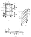
Mittig durch Scharniere (7) geteilte Gelenkböden (9) sind horizontal mit den Seitenwänden (2) durch Scharniere (7) verbunden. Die Gelenkböden (9) sind mit einer vertikalen Verbindungsstange (16) verbunden, die für eine gleichmäßige Stellung der Böden (9) sorgt. Die Verbindungsstange (16) weist kleine Magnete (8) an ihrer Außenseite auf. Diese Magnete (8) dienen einerseits im aufgestellten Zustand dazu, die Rückwand (4) zu halten und anderseits in der zusammengeklappten Stellung dazu, zwei nebeneinander spiegelbildlich gestapelte Schränkchen aneinander zu befestigen. Am unteren Rand der Seiten (2) ist je eine horizontale Fixierungsplatte (3c) befestigt, an die je zwei schwenkbare Räder (6) mit Anschraubplatte (6b) montiert sind und ein leichtes, schnelles Austauschen von Rädern oder Radersatz, für die jeweiligen Bodenverhältnisse am Einsatzort ermöglicht.
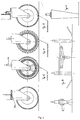
Nach Fig. 4 weisen die Räder des Typs A Kunststoffelgen-Gleitlager und Vollgummi-Laufflächen auf. Diese Räder sind zum Überwinden von Türschwellen oder für festen Boden geeignet z.B. in Turnhallen. Zwei der Rollen sind mit Feststellern versehen. Für den Einsatz im Freien, sind Hartgummiräder des Typs B für den steinigen, felsigen Boden, und luftbereifte Räder des Typs C für den morastigen tiefen Boden vorgesehen. Für den Einsatz auf eisigem, verschneiten Boden, ist das Kufen/Skisystem des Typs D mit angebrachter Dornenarretierung zum Feststellen für den sicheren Stand des Medicinal-Nachschränkchen vorgesehen. In einer weiteren Ausführungsform sind zwei der schwenkbaren Räder (6) durch Gummistopper des Typs E ersetzt. Durch Ankippen des Schränkchens kann dieses gefahren werden und standfest wieder abgestellt werden.In the following the invention is explained in more detail by means of examples with reference to the accompanying drawings, wherein
Articulated floors (9) divided in the middle by hinges (7) are connected horizontally to the side walls (2) by hinges (7). The articulated floors (9) are connected to a vertical connecting rod (16) which ensures that the floors (9) are evenly positioned. The connecting rod (16) has small magnets (8) on its outside. These magnets (8) serve, on the one hand, to hold the rear wall (4) in the set-up state and, on the other hand, in the folded position, to fasten two cabinets stacked next to one another in mirror image. A horizontal fixing plate (3c) is attached to the lower edge of the sides (2), to each of which two swiveling wheels (6) with screw-on plate (6b) are mounted and an easy, quick exchange of wheels or wheel replacement for the respective ground conditions on Location allows.
According to Fig. 4, the type A wheels have plastic rims and solid rubber treads. These bikes are suitable for overcoming door thresholds or for firm ground, for example in gyms. Two of the rollers are equipped with locks. For outdoor use, type B hard rubber wheels are intended for stony, rocky ground, and type C pneumatic tires for muddy deep ground. For use on icy, snowy ground, the type D runners / ski system with attached thorn lock is designed to hold the Medicinal bedside table securely in place. In a further embodiment, two of the swiveling wheels (6) are replaced by type E rubber stoppers. By tilting the cabinet, it can be driven and set down again steadily.
Am obersten Innenrand der Seiten (2) ist je eine Fixierungsplatte (3b) befestigt.
Im zusammengeklappten Zustand des Schränkchens stoßen die Fixierplatten (3b) und
(3c) jeweils gegeneinander um die gefaltete Konstruktion zu stabilisieren, so daß viele
Schränkchen übereinander stapelbar sind.
Die Türen (5) und die Rückwand (4) weisen innenseitig kleine Magnete (8) auf und
sind mittels der Scharniere (7) um 270° nach außen schwenkbar. Beim Schwenken
um 270° liegen sie jeweils parallel an der Seitenwand (2) an und haben Kontakt mit
den kleinen Magneten (8). Nach Fig. 3 und 4 stehen die Rückwand (4) sowie die Vordertüren
auf der Fixierungsplatte (3c) auf.A fixing plate (3b) is attached to the top inner edge of each side (2).
When the cabinet is folded, the fixing plates (3b) and (3c) each abut against one another in order to stabilize the folded construction, so that many cabinets can be stacked on top of one another.
The doors (5) and the rear wall (4) have small magnets (8) on the inside and can be pivoted outward by 270 ° by means of the hinges (7). When swiveling through 270 °, they lie parallel to the side wall (2) and are in contact with the small magnets (8). 3 and 4, the rear wall (4) and the front doors stand on the fixing plate (3c).
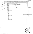
An einer Seitenwand (2) sind zwei Profilschienen (10) zur Führung der Tischplatte
(11) befestigt. An der Profilschiene (10) sind Federbeaufschlagte Indexstifte
(10a) befestigt, die zusammen mit unter der Tischplatte (11) angebrachten Lochleisten
für die Höhenverstellung vorgesehen sind. Die Tischplatte ist im Neigungswinkel nach
Wunsch durch Feststellen des Schraubknopfes (11a) einstellbar. Unter der Tischplatte
(11) ist eine ausklappbare, längenverstellbare und feststellbare anti-kipp Teleskopstange
(12) angebracht. Die Teleskopstange (12) ist so einstellbar, daß sie eine feste Stütze
bei horizontaler Stellung der Tischplatte (11) bildet. Ein ungewolltes Kippen des
Schränkchens bei schwerer Belastung am Tischplattenrand wird so verhindert. Die Teleskopstange
(12) besteht aus einem Außenrohr (13) an dem ein Federdruckknopf
(13a) angebracht ist und einem gelochten Innenrohr (20).Am Ende des Innenrohrs (20)
befindet sich ein Fuß (21), der eine breite Auflagefläche für ein Aufstellen auf dem
Boden oder der Matratze aufweist.
Die Teleskopstange (12) ist unter der Tischplatte (11) mittels Gelenk (22) fest
montiert und wird zur Arretierung in die Halteklammer (23) eingerastet.
Ein fahrbares, parallelogrammartig zusammenfaltbares Nachtschränkchen (1) nach
Fig. 6-8, kann mit folgenden Teilen hergestellt werden:
- zwei rechteckige Metallplatten aus denen zwei Ecken in der Breite der vorgesehenen Anschlagflächen (3) ausgestanzt sind als Seitenwände (2).
- eine längliche, rechteckige Metallplatte mit zur Verstärkung umgebogenen Rändern als Rückwand (4)
- zwei rechteckige Metallplatten mit zur Verstärkung umgebogenen Rändern als Türen (5) mit ausgestanzten Grifflöchern (5a)
- Scharniere (8) zur Verbindung der Türen (5) und Rückwand (4) mit der Seitenwand (2)
- Flügelschrauben (4a) zur Fixierung der Rückwand (4) an der zweiten Seitenwand (2)
- Muttern (4b) als Gegenstück zu den Flügelschrauben (4a)
- Vier luftbereifte Steckräder (6) oder Lenkrollen 75 mm hoch, wovon zwei feststellbar sind
- Vier Gelenkböden mit ringsum zur Verstärkung senkrecht nach unten gebogenen Kanten
- Magnete (8) die die Türen (5) im geschlossenen Zustand halten
- 16 Gelenknieten (9a) zum beweglichen Fixieren der Gelenkböden (9) an den Anschlagflächen (3) der Seitenwände (2)
- Vier Steckhülsen (6a) zur Aufnahme der Steckräder (6)
- Zwei Profilschienen (10) zur Aufnahme der Führungsstäbe (14) der Tischplatte (11)
- Zwei Feststellstifte (16) zur Arretierung der Führungsstäbe (14) in der gewünschten Höhe
- Eine Teleskopstange (12) bestehend aus einem Außenrohr (13), einem Federdruckknopf (13a), einem Innenrohr (20) und einem Fuß (21) sowie einem Gelenk (22)
- eine Halteklammer (23) zum einrasten der Teleskopstange (12)
- Zwei Handgriffe (17) zum Anbringen an die Führunssstäbe (14)
- Zwei Halterungsnasen (18) am Ende der Tischplatte (11)
- Eine Arretierung (15) zum Sichern der zusammengelegten Konstruktion
Auf eine Seitenwand (2) werden zwei Profilschienen (10) an den äußeren Längskanten angebracht. Als unterer Abschluß der Profilschienen (10) wird bündig mit der Unterkante dieser Seitenwand (2) ein U-Profil angebracht. In diesen als U-Profil ausgebildeten Abschlußkanten werden Steckhülsen (6a) für Steckbolsen der leicht auswechselbaren Räder (6) eingebracht. Vier Gelenkböden (9) werden mit senkrecht nach unten zeigenden Kantenflächen waagerecht zwischen den Seitenwänden (2)
Am Ende der Tischplatte (11) werden Halterungsnasen (18) montiert.
Eine Verriegelung (15) hält im zusammengelegten Zustand beide Seitenwände zusammen.
Um das Sanitätsnachtschränkchen zu transportieren und zu lagern sind folgende Schritte vorher notwendig:
Die Tischplatte (11) des Nachtschränkchens (1) kann durch schwenken, in senkrechter Position, parallel zu den Führungsstäben zwischen den Profilschienen (10) eingeschoben werden. Die Türen (5) können um ca. 270° nach außen geschwenkt werden, bis sie auf der Außenseite der Seitenwand (2) anliegen, an der sie mit den Scharnieren (7) gehalten sind. Durch lösen der Flügelschrauben (4a) aus den angeschweißten Muttern (4b), kann die Rückwand (4) geöffnet werden. Die Flügelschrauben (4a) können danach wieder eingeschraubt werden. Die Rückwand (4) kann um ca. 270° nach außen geschwenkt werden bis sie auf der Außenseite der Seitenwand (2), an der sie mit Scharnieren (7) befestigt ist, die bereits zurückgeklappten Türen (5) überdeckt. Die so offene Konstruktion kann zum Falten nach hinten auf den Boden gelegt werden. Durch verschieben einer Seitenwand (2) faltet sich die ganze Konstruktion in der Art eines Parallelogramms
Die zusammengelegte Konstruktion wird mit der Verriegelung (15) in dieser Position gesichert.Two profile rails (10) for guiding the table top (11) are attached to a side wall (2). Spring-loaded index pins (10a) are attached to the profile rail (10), which are provided together with perforated strips for height adjustment under the table top (11). The table top can be adjusted in the angle of inclination by locking the screw button (11a). A fold-out, length-adjustable and lockable anti-tip telescopic rod (12) is attached under the table top (11). The telescopic rod (12) is adjustable so that it forms a firm support when the table top (11) is in a horizontal position. This prevents the cabinet from tipping unintentionally under heavy loads on the edge of the table top. The telescopic rod (12) consists of an outer tube (13) to which a spring push button (13a) is attached and a perforated inner tube (20). At the end of the inner tube (20) there is a foot (21) that has a wide contact surface for one Set up on the floor or the mattress.
The telescopic rod (12) is securely mounted under the table top (11) by means of a joint (22) and is locked into the holding bracket (23) for locking.
A mobile bedside cabinet (1) according to Fig. 6-8, which can be folded in a parallelogram, can be manufactured with the following parts:
- two rectangular metal plates from which two corners are punched out in the width of the intended stop surfaces (3) as side walls (2).
- an elongated, rectangular metal plate with edges bent over for reinforcement as the rear wall (4)
- two rectangular metal plates with edges bent over to reinforce them as doors (5) with punched-out grip holes (5a)
- Hinges (8) for connecting the doors (5) and rear wall (4) to the side wall (2)
- Wing screws (4a) for fixing the rear wall (4) to the second side wall (2)
- Nuts (4b) as a counterpart to the wing screws (4a)
- Four pneumatic tires (6) or swivel castors 75 mm high, two of which can be locked
- Four hinged shelves with vertically bent edges all around for reinforcement
- Magnets (8) that keep the doors (5) closed
- 16 articulated rivets (9a) for movably fixing the articulated floors (9) to the stop surfaces (3) of the side walls (2)
- Four plug sleeves (6a) for receiving the plug-in wheels (6)
- Two profile rails (10) for receiving the guide rods (14) of the table top (11)
- Two locking pins (16) for locking the guide rods (14) at the desired height
- A telescopic rod (12) consisting of an outer tube (13), a spring push button (13a), an inner tube (20) and a foot (21) and a joint (22)
- a retaining clip (23) for locking the telescopic rod (12)
- Two handles (17) for attachment to the guide rods (14)
- Two mounting lugs (18) at the end of the table top (11)
- A lock (15) to secure the collapsed structure
Two profile rails (10) are attached to the outer longitudinal edges on a side wall (2). A U-profile is installed flush with the lower edge of this side wall (2) as the lower end of the profile rails (10). Plug sleeves (6a) for plug pins of the easily exchangeable wheels (6) are introduced into these end edges, which are designed as U-profiles. Four hinged shelves (9) are pivotally mounted on the stop surfaces (3) with edge surfaces pointing vertically downwards between the side walls (2), each with 4 joint rivets (9a). The distance between the articulated floors (9) to the side walls (2) is such that a displacement of the side walls (2) upwards without the edge surfaces abutting the side wall (2) is only possible on one side. Movement on the other side is inhibited by the edge surface abutting the side wall (2). An articulated floor (9) is mounted so that it is flush with the upper edges of the cabinet (1). The second floor (9) is approx. 25 cm below. A third floor (9) is attached about 20 cm further below the second floor (9) and a fourth floor (9) is mounted just above the inner edges of the side walls (2) which are designed as a U-profile. The area in front of the first and second as well as in front of the third and fourth hinged floor (9) is covered with a movable door (5) which is attached to a side wall (2) with hinges (7). In the stop surface (3) of the other side wall (2), on which the door (5) strikes when closed, two magnets (8) are attached to hold the doors. Thanks to punched holes (5a) and hinges (7), the doors (5) can be pivoted outwards by 270 ° so that they lie flat against the side wall (2). A rear wall (4) is mounted with hinges (7) on the same side wall (2) as the doors (5). For medical use, the rear wall (4) is screwed to the stop surface (3) of the second side wall (2). For storage or transportation, after loosening the thumbscrews (4a), it can be swiveled outwards by 270 ° over the doors (5) that have already been swung back. In the profile rails (10) guide rods (14) of the table top (11) are inserted, which hold the desired table top height by locking pins (16). A telescopic rod (12) consisting of an outer tube (13), an inner tube (20) and a foot (21) is mounted on a joint (22) under the table top (11) and can be snapped into the retaining clip (23) when not in use. Handles (17) are attached to the guide rods (14).
At the end of the table top (11) mounting lugs (18) are mounted.
A lock (15) holds both side walls together in the folded state.
In order to transport and store the medical bedside cabinet, the following steps are necessary:
The table top (11) of the bedside table (1) can be inserted between the profile rails (10) by swiveling, in a vertical position, parallel to the guide rods. The doors (5) can be pivoted outwards by approx. 270 ° until they rest on the outside of the side wall (2) on which they are held by the hinges (7). The rear wall (4) can be opened by loosening the wing screws (4a) from the welded nuts (4b). The wing screws (4a) can then be screwed in again. The rear wall (4) can be pivoted outward by approx. 270 ° until it covers the doors (5) already folded back on the outside of the side wall (2), to which it is attached with hinges (7). The construction, which is open in this way, can be laid on the floor for folding backwards. By moving one side wall (2) the whole construction folds in the manner of a parallelogram
The folded construction is secured in this position with the lock (15).
Claims (10)
Applications Claiming Priority (2)
| Application Number | Priority Date | Filing Date | Title |
|---|---|---|---|
| DE19836437 | 1998-08-12 | ||
| DE19836437 | 1998-08-12 |
Publications (3)
| Publication Number | Publication Date |
|---|---|
| EP0979627A2 true EP0979627A2 (en) | 2000-02-16 |
| EP0979627A3 EP0979627A3 (en) | 2001-01-31 |
| EP0979627B1 EP0979627B1 (en) | 2003-07-23 |
Family
ID=7877238
Family Applications (1)
| Application Number | Title | Priority Date | Filing Date |
|---|---|---|---|
| EP99115935A Expired - Lifetime EP0979627B1 (en) | 1998-08-12 | 1999-08-12 | Foldable medical bedside table |
Country Status (3)
| Country | Link |
|---|---|
| EP (1) | EP0979627B1 (en) |
| AT (1) | ATE245372T1 (en) |
| DE (3) | DE59906338D1 (en) |
Cited By (3)
| Publication number | Priority date | Publication date | Assignee | Title |
|---|---|---|---|---|
| WO2011098350A1 (en) * | 2010-02-12 | 2011-08-18 | BSH Bosch und Siemens Hausgeräte GmbH | Elevating platform |
| WO2011098354A1 (en) * | 2010-02-12 | 2011-08-18 | BSH Bosch und Siemens Hausgeräte GmbH | Elevating platform |
| US8100061B2 (en) | 2008-06-13 | 2012-01-24 | Hill-Rom Services, Inc. | Item support apparatuses and systems for bedside |
Families Citing this family (4)
| Publication number | Priority date | Publication date | Assignee | Title |
|---|---|---|---|---|
| EP1208777A1 (en) * | 2000-11-27 | 2002-05-29 | Michel Leblanc B.V.B.A. | Collapsible display |
| FR2817454B1 (en) * | 2000-12-06 | 2003-07-18 | Daniel Dassis | FURNITURE FOR ELEMENT SUCH AS SINK OR BASIN |
| US8256629B2 (en) * | 2009-06-25 | 2012-09-04 | Shou Qiang Zhu | Foldable and portable storage shelf |
| DE102017108179A1 (en) * | 2017-04-18 | 2018-10-18 | Cornelius Bobbert | table |
Citations (9)
| Publication number | Priority date | Publication date | Assignee | Title |
|---|---|---|---|---|
| DE1943744A1 (en) | 1969-01-03 | 1971-11-25 | Altenburg Elektrowaerme | Device for the automatic regulation of the negative pressure for carpet knockers and sweepers |
| DE2339197A1 (en) | 1973-08-02 | 1975-02-13 | Werner Cordes | Collapsible transport cage on wheels - has one side wall rigidly attached and other hinged to rear wall |
| US4326731A (en) | 1979-10-01 | 1982-04-27 | Stephen Woychio | Folding cart |
| DE8317461U1 (en) | 1983-06-15 | 1983-11-17 | aspa-Fördergeräte A. Schleifenbaum GmbH & Co KG, 5948 Schmallenberg | TRANSPORT TROLLEY WITH AN ANGULAR, RIGID BASE FRAME |
| US4878682A (en) | 1988-07-22 | 1989-11-07 | Lee David M | Center collapsible transport cart |
| DE3932036C1 (en) | 1989-09-26 | 1990-09-06 | Wilh. Berg Gmbh & Co Kg, 5990 Altena, De | Hospital bedside table assembly - incorporates drawers and cupboard doors and has raised rim on three sides of top surface |
| DE9107787U1 (en) | 1991-06-25 | 1992-08-27 | Schoenfeld, Hans Victor, 3180 Wolfsburg, De | |
| DE9406270U1 (en) | 1994-04-15 | 1994-06-16 | Muehlhausen Juergen | Multipurpose trolleys / transport trolleys to hold all kinds of goods |
| DE9418630U1 (en) | 1994-11-22 | 1995-02-16 | Vauth Sagel Gmbh & Co | Kit for a bedside table |
Family Cites Families (5)
| Publication number | Priority date | Publication date | Assignee | Title |
|---|---|---|---|---|
| GB919483A (en) * | 1958-08-26 | 1963-02-27 | John Leslie Stableford | Improvements relating to tables, cabinets and the like |
| FR1597418A (en) * | 1968-06-27 | 1970-06-29 | ||
| US3759599A (en) * | 1971-09-27 | 1973-09-18 | Cornelius Co | Collapsible storage assembly |
| DE19540059C1 (en) * | 1995-10-27 | 1996-06-13 | Arnold L & C | Combined bed and night table for use in hospitals |
| DE19623138A1 (en) * | 1996-06-10 | 1997-12-11 | Erich Sussmann | Shelving which folds into small space |
-
1999
- 1999-08-12 DE DE59906338T patent/DE59906338D1/en not_active Expired - Lifetime
- 1999-08-12 DE DE29914100U patent/DE29914100U1/en not_active Expired - Lifetime
- 1999-08-12 DE DE19937646A patent/DE19937646A1/en not_active Withdrawn
- 1999-08-12 AT AT99115935T patent/ATE245372T1/en not_active IP Right Cessation
- 1999-08-12 EP EP99115935A patent/EP0979627B1/en not_active Expired - Lifetime
Patent Citations (9)
| Publication number | Priority date | Publication date | Assignee | Title |
|---|---|---|---|---|
| DE1943744A1 (en) | 1969-01-03 | 1971-11-25 | Altenburg Elektrowaerme | Device for the automatic regulation of the negative pressure for carpet knockers and sweepers |
| DE2339197A1 (en) | 1973-08-02 | 1975-02-13 | Werner Cordes | Collapsible transport cage on wheels - has one side wall rigidly attached and other hinged to rear wall |
| US4326731A (en) | 1979-10-01 | 1982-04-27 | Stephen Woychio | Folding cart |
| DE8317461U1 (en) | 1983-06-15 | 1983-11-17 | aspa-Fördergeräte A. Schleifenbaum GmbH & Co KG, 5948 Schmallenberg | TRANSPORT TROLLEY WITH AN ANGULAR, RIGID BASE FRAME |
| US4878682A (en) | 1988-07-22 | 1989-11-07 | Lee David M | Center collapsible transport cart |
| DE3932036C1 (en) | 1989-09-26 | 1990-09-06 | Wilh. Berg Gmbh & Co Kg, 5990 Altena, De | Hospital bedside table assembly - incorporates drawers and cupboard doors and has raised rim on three sides of top surface |
| DE9107787U1 (en) | 1991-06-25 | 1992-08-27 | Schoenfeld, Hans Victor, 3180 Wolfsburg, De | |
| DE9406270U1 (en) | 1994-04-15 | 1994-06-16 | Muehlhausen Juergen | Multipurpose trolleys / transport trolleys to hold all kinds of goods |
| DE9418630U1 (en) | 1994-11-22 | 1995-02-16 | Vauth Sagel Gmbh & Co | Kit for a bedside table |
Cited By (3)
| Publication number | Priority date | Publication date | Assignee | Title |
|---|---|---|---|---|
| US8100061B2 (en) | 2008-06-13 | 2012-01-24 | Hill-Rom Services, Inc. | Item support apparatuses and systems for bedside |
| WO2011098350A1 (en) * | 2010-02-12 | 2011-08-18 | BSH Bosch und Siemens Hausgeräte GmbH | Elevating platform |
| WO2011098354A1 (en) * | 2010-02-12 | 2011-08-18 | BSH Bosch und Siemens Hausgeräte GmbH | Elevating platform |
Also Published As
| Publication number | Publication date |
|---|---|
| DE59906338D1 (en) | 2003-08-28 |
| ATE245372T1 (en) | 2003-08-15 |
| DE19937646A1 (en) | 2000-03-02 |
| EP0979627A3 (en) | 2001-01-31 |
| DE29914100U1 (en) | 1999-12-23 |
| EP0979627B1 (en) | 2003-07-23 |
Similar Documents
| Publication | Publication Date | Title |
|---|---|---|
| DE4320099A1 (en) | Suitcase on wheels | |
| DE102008036578A1 (en) | Extendible head and foot panels for an ambulance bed | |
| DE102006034888B3 (en) | Roll container e.g. for bulk goods, has chassis and construction with chassis has roller assembly base with two steering wheels | |
| EP2063735B1 (en) | Table, in particular school desk | |
| EP0138116A2 (en) | Collapsible wheelchair | |
| DE60218801T2 (en) | Collapsible trolley with shelf | |
| EP0979627B1 (en) | Foldable medical bedside table | |
| DE3446490A1 (en) | Mobile sales kiosk | |
| DE60017122T2 (en) | COLLAPSIBLE CARRIER WITH SHELVES | |
| DE102019125729B3 (en) | Foldable structural frame for a car | |
| EP0185105A1 (en) | Collapsible item of furniture | |
| DE202016008663U1 (en) | training device | |
| DE102020206185B4 (en) | Side trolley and kitchen system with a side trolley | |
| EP2857278A1 (en) | Transportation system | |
| DE202012008101U1 (en) | Bühnenpodest element | |
| AT503618B1 (en) | STACKABLE TABLE | |
| DE102009033418B3 (en) | Portable booster seat for toilets, particularly for elderly and disabled persons and care recipients, has seat frame with top-side seat surface and collapsible support frame between seat frame and pool edge of toilet | |
| DE3319877C2 (en) | ||
| DE102011000610A1 (en) | Cart for transporting an open-ended stacking box, has carriage device, where wheels or runners are provided on both sides of carriage device, where support is provided with depth | |
| DE202011000132U1 (en) | Presentation device, in particular for exhibiting shoes | |
| DE1270221B (en) | Rehabilitation device to make walking easier for the physically handicapped | |
| DE102009042516B4 (en) | Serving table for serving food | |
| DE102016118061A1 (en) | Table transport device | |
| DE19540055C1 (en) | Combined hospital bed and night table | |
| EP1605795B1 (en) | Table with two folding leg elements |
Legal Events
| Date | Code | Title | Description |
|---|---|---|---|
| PUAI | Public reference made under article 153(3) epc to a published international application that has entered the european phase |
Free format text: ORIGINAL CODE: 0009012 |
|
| AK | Designated contracting states |
Kind code of ref document: A2 Designated state(s): AT BE CH CY DE DK ES FI FR GB GR IE IT LI LU MC NL PT SE |
|
| AX | Request for extension of the european patent |
Free format text: AL;LT;LV;MK;RO;SI |
|
| PUAL | Search report despatched |
Free format text: ORIGINAL CODE: 0009013 |
|
| AK | Designated contracting states |
Kind code of ref document: A3 Designated state(s): AT BE CH CY DE DK ES FI FR GB GR IE IT LI LU MC NL PT SE |
|
| AX | Request for extension of the european patent |
Free format text: AL;LT;LV;MK;RO;SI |
|
| 17P | Request for examination filed |
Effective date: 20010730 |
|
| AKX | Designation fees paid |
Free format text: AT BE CH CY DE DK ES FI FR GB GR IE IT LI LU MC NL PT SE |
|
| 17Q | First examination report despatched |
Effective date: 20020118 |
|
| GRAH | Despatch of communication of intention to grant a patent |
Free format text: ORIGINAL CODE: EPIDOS IGRA |
|
| GRAH | Despatch of communication of intention to grant a patent |
Free format text: ORIGINAL CODE: EPIDOS IGRA |
|
| GRAA | (expected) grant |
Free format text: ORIGINAL CODE: 0009210 |
|
| AK | Designated contracting states |
Designated state(s): AT BE CH CY DE DK ES FI FR GB GR IE IT LI LU MC NL PT SE |
|
| PG25 | Lapsed in a contracting state [announced via postgrant information from national office to epo] |
Ref country code: NL Free format text: LAPSE BECAUSE OF FAILURE TO SUBMIT A TRANSLATION OF THE DESCRIPTION OR TO PAY THE FEE WITHIN THE PRESCRIBED TIME-LIMIT Effective date: 20030723 Ref country code: IT Free format text: LAPSE BECAUSE OF FAILURE TO SUBMIT A TRANSLATION OF THE DESCRIPTION OR TO PAY THE FEE WITHIN THE PRESCRIBED TIME-LIMIT;WARNING: LAPSES OF ITALIAN PATENTS WITH EFFECTIVE DATE BEFORE 2007 MAY HAVE OCCURRED AT ANY TIME BEFORE 2007. THE CORRECT EFFECTIVE DATE MAY BE DIFFERENT FROM THE ONE RECORDED. Effective date: 20030723 Ref country code: IE Free format text: LAPSE BECAUSE OF FAILURE TO SUBMIT A TRANSLATION OF THE DESCRIPTION OR TO PAY THE FEE WITHIN THE PRESCRIBED TIME-LIMIT Effective date: 20030723 Ref country code: GB Free format text: LAPSE BECAUSE OF FAILURE TO SUBMIT A TRANSLATION OF THE DESCRIPTION OR TO PAY THE FEE WITHIN THE PRESCRIBED TIME-LIMIT Effective date: 20030723 Ref country code: FI Free format text: LAPSE BECAUSE OF FAILURE TO SUBMIT A TRANSLATION OF THE DESCRIPTION OR TO PAY THE FEE WITHIN THE PRESCRIBED TIME-LIMIT Effective date: 20030723 |
|
| REG | Reference to a national code |
Ref country code: GB Ref legal event code: FG4D Free format text: NOT ENGLISH |
|
| REG | Reference to a national code |
Ref country code: CH Ref legal event code: EP |
|
| PG25 | Lapsed in a contracting state [announced via postgrant information from national office to epo] |
Ref country code: LU Free format text: LAPSE BECAUSE OF NON-PAYMENT OF DUE FEES Effective date: 20030812 Ref country code: CY Free format text: LAPSE BECAUSE OF FAILURE TO SUBMIT A TRANSLATION OF THE DESCRIPTION OR TO PAY THE FEE WITHIN THE PRESCRIBED TIME-LIMIT Effective date: 20030812 Ref country code: AT Free format text: LAPSE BECAUSE OF NON-PAYMENT OF DUE FEES Effective date: 20030812 |
|
| REG | Reference to a national code |
Ref country code: IE Ref legal event code: FG4D Free format text: GERMAN |
|
| REF | Corresponds to: |
Ref document number: 59906338 Country of ref document: DE Date of ref document: 20030828 Kind code of ref document: P |
|
| PG25 | Lapsed in a contracting state [announced via postgrant information from national office to epo] |
Ref country code: MC Free format text: LAPSE BECAUSE OF NON-PAYMENT OF DUE FEES Effective date: 20030831 Ref country code: LI Free format text: LAPSE BECAUSE OF NON-PAYMENT OF DUE FEES Effective date: 20030831 Ref country code: CH Free format text: LAPSE BECAUSE OF NON-PAYMENT OF DUE FEES Effective date: 20030831 Ref country code: BE Free format text: LAPSE BECAUSE OF NON-PAYMENT OF DUE FEES Effective date: 20030831 |
|
| PG25 | Lapsed in a contracting state [announced via postgrant information from national office to epo] |
Ref country code: SE Free format text: LAPSE BECAUSE OF FAILURE TO SUBMIT A TRANSLATION OF THE DESCRIPTION OR TO PAY THE FEE WITHIN THE PRESCRIBED TIME-LIMIT Effective date: 20031023 Ref country code: GR Free format text: LAPSE BECAUSE OF FAILURE TO SUBMIT A TRANSLATION OF THE DESCRIPTION OR TO PAY THE FEE WITHIN THE PRESCRIBED TIME-LIMIT Effective date: 20031023 Ref country code: DK Free format text: LAPSE BECAUSE OF FAILURE TO SUBMIT A TRANSLATION OF THE DESCRIPTION OR TO PAY THE FEE WITHIN THE PRESCRIBED TIME-LIMIT Effective date: 20031023 |
|
| PG25 | Lapsed in a contracting state [announced via postgrant information from national office to epo] |
Ref country code: ES Free format text: LAPSE BECAUSE OF FAILURE TO SUBMIT A TRANSLATION OF THE DESCRIPTION OR TO PAY THE FEE WITHIN THE PRESCRIBED TIME-LIMIT Effective date: 20031103 |
|
| NLV1 | Nl: lapsed or annulled due to failure to fulfill the requirements of art. 29p and 29m of the patents act | ||
| PG25 | Lapsed in a contracting state [announced via postgrant information from national office to epo] |
Ref country code: PT Free format text: LAPSE BECAUSE OF FAILURE TO SUBMIT A TRANSLATION OF THE DESCRIPTION OR TO PAY THE FEE WITHIN THE PRESCRIBED TIME-LIMIT Effective date: 20031223 |
|
| GBV | Gb: ep patent (uk) treated as always having been void in accordance with gb section 77(7)/1977 [no translation filed] |
Effective date: 20030723 |
|
| REG | Reference to a national code |
Ref country code: IE Ref legal event code: FD4D |
|
| BERE | Be: lapsed |
Owner name: *DONTENVILL CHRISTIAN Effective date: 20030831 |
|
| REG | Reference to a national code |
Ref country code: CH Ref legal event code: PL |
|
| ET | Fr: translation filed | ||
| PLBE | No opposition filed within time limit |
Free format text: ORIGINAL CODE: 0009261 |
|
| STAA | Information on the status of an ep patent application or granted ep patent |
Free format text: STATUS: NO OPPOSITION FILED WITHIN TIME LIMIT |
|
| 26N | No opposition filed |
Effective date: 20040426 |
|
| REG | Reference to a national code |
Ref country code: FR Ref legal event code: PLFP Year of fee payment: 18 |
|
| REG | Reference to a national code |
Ref country code: FR Ref legal event code: PLFP Year of fee payment: 19 |
|
| REG | Reference to a national code |
Ref country code: FR Ref legal event code: PLFP Year of fee payment: 20 |
|
| PGFP | Annual fee paid to national office [announced via postgrant information from national office to epo] |
Ref country code: FR Payment date: 20180824 Year of fee payment: 20 |
|
| PGFP | Annual fee paid to national office [announced via postgrant information from national office to epo] |
Ref country code: DE Payment date: 20181001 Year of fee payment: 20 |
|
| REG | Reference to a national code |
Ref country code: DE Ref legal event code: R071 Ref document number: 59906338 Country of ref document: DE |