EP0978390B1 - Inkjet printhead calibration - Google Patents
Inkjet printhead calibration Download PDFInfo
- Publication number
- EP0978390B1 EP0978390B1 EP99306098A EP99306098A EP0978390B1 EP 0978390 B1 EP0978390 B1 EP 0978390B1 EP 99306098 A EP99306098 A EP 99306098A EP 99306098 A EP99306098 A EP 99306098A EP 0978390 B1 EP0978390 B1 EP 0978390B1
- Authority
- EP
- European Patent Office
- Prior art keywords
- printhead
- test patterns
- test
- inkjet
- test pattern
- Prior art date
- Legal status (The legal status is an assumption and is not a legal conclusion. Google has not performed a legal analysis and makes no representation as to the accuracy of the status listed.)
- Expired - Lifetime
Links
Images


Classifications
-
- B—PERFORMING OPERATIONS; TRANSPORTING
- B41—PRINTING; LINING MACHINES; TYPEWRITERS; STAMPS
- B41J—TYPEWRITERS; SELECTIVE PRINTING MECHANISMS, i.e. MECHANISMS PRINTING OTHERWISE THAN FROM A FORME; CORRECTION OF TYPOGRAPHICAL ERRORS
- B41J2/00—Typewriters or selective printing mechanisms characterised by the printing or marking process for which they are designed
- B41J2/005—Typewriters or selective printing mechanisms characterised by the printing or marking process for which they are designed characterised by bringing liquid or particles selectively into contact with a printing material
- B41J2/01—Ink jet
- B41J2/21—Ink jet for multi-colour printing
- B41J2/2132—Print quality control characterised by dot disposition, e.g. for reducing white stripes or banding
- B41J2/2135—Alignment of dots
-
- B—PERFORMING OPERATIONS; TRANSPORTING
- B41—PRINTING; LINING MACHINES; TYPEWRITERS; STAMPS
- B41J—TYPEWRITERS; SELECTIVE PRINTING MECHANISMS, i.e. MECHANISMS PRINTING OTHERWISE THAN FROM A FORME; CORRECTION OF TYPOGRAPHICAL ERRORS
- B41J19/00—Character- or line-spacing mechanisms
- B41J19/14—Character- or line-spacing mechanisms with means for effecting line or character spacing in either direction
- B41J19/142—Character- or line-spacing mechanisms with means for effecting line or character spacing in either direction with a reciprocating print head printing in both directions across the paper width
- B41J19/145—Dot misalignment correction
-
- B—PERFORMING OPERATIONS; TRANSPORTING
- B41—PRINTING; LINING MACHINES; TYPEWRITERS; STAMPS
- B41J—TYPEWRITERS; SELECTIVE PRINTING MECHANISMS, i.e. MECHANISMS PRINTING OTHERWISE THAN FROM A FORME; CORRECTION OF TYPOGRAPHICAL ERRORS
- B41J29/00—Details of, or accessories for, typewriters or selective printing mechanisms not otherwise provided for
- B41J29/38—Drives, motors, controls or automatic cut-off devices for the entire printing mechanism
- B41J29/393—Devices for controlling or analysing the entire machine ; Controlling or analysing mechanical parameters involving printing of test patterns
-
- B—PERFORMING OPERATIONS; TRANSPORTING
- B41—PRINTING; LINING MACHINES; TYPEWRITERS; STAMPS
- B41J—TYPEWRITERS; SELECTIVE PRINTING MECHANISMS, i.e. MECHANISMS PRINTING OTHERWISE THAN FROM A FORME; CORRECTION OF TYPOGRAPHICAL ERRORS
- B41J19/00—Character- or line-spacing mechanisms
- B41J19/14—Character- or line-spacing mechanisms with means for effecting line or character spacing in either direction
- B41J19/142—Character- or line-spacing mechanisms with means for effecting line or character spacing in either direction with a reciprocating print head printing in both directions across the paper width
Definitions
- This invention relates generally to printers, plotters, and marking devices, and more particularly, to inkjet printers, plotters and marking devices having multiple printheads for multi-color printing.
- Inkjet marking devices typically include one or more inkjet pens mounted on a carriage. Each pen includes a printhead having a plurality of inkjet nozzles. During printing, the carriage moves across a media sheet while the nozzles discharge ink drops. The timing of the ink drop ejection is controlled to precisely place the drops at desired locations.
- a typical multi-color inkjet marking device includes two or more inkjet pens with respective printheads.
- One pen stores black ink, while the others store ink of one or more colors, (e.g., cyan, magenta or yellow).
- the four inks represent four base colors which are applied to a media sheet to derive any of multiple colors.
- the pens typically are mounted in stalls within the carriage. To achieve desired print quality the ink colors need to be precisely placed at desired locations on the media sheet. To do so the pen printheads are to be maintained in precise alignment.
- the pens typically are loaded and replaced periodically by the end user. As a result, mechanical misalignment is likely to occur. Mechanical misalignment results in offsets of one or more pens' nozzles relative to the other pens' nozzles. This misalignment manifests as a misregistration of the dots forming a print symbol, image, or graphic representation. Other sources of misalignment also may occur due to the speed of motion of the carriage, the curvature of the platen and the spray of the nozzles.
- U.S. Patent No. 5,289,208 issued February 22, 1994 of Robert D. Haselby entitled "Automatic Print Cartridge Alignment Sensor System” discloses a technique in which an optical sensor detects the position of test line segments. Vertical alignment is achieved by printing a plurality of non-overlapping horizontal test line segments. A quad photodiode detector detects the vertical positions of the horizontal test line segments relative to a fixed reference. Horizontal alignment is achieved by printing a plurality of non-overlapping vertical test line segments in a vertical direction. If properly aligned the line segments connect to form a straight line (e.g., for printing 2 line segments the line is 2 line segments long). If misaligned, the line segments form an angled line (e.g., for printing 2 line segments the line is 2 line segments long). A quad photodiode detector detects the horizontal positions of the vertical test line segments to determine if the segments are aligned.
- U.S. Patent No. 5,451,990 discloses a reference pattern for use in performing image registration for multiple inkjet cartridges.
- the reference pattern includes four test patterns. One test pattern is generated along the scan axis to exercise the pens. It includes an individual section for each color. A second test pattern is used to test for pen offset due to speed and curvature. The second pattern is a bidirectional test pattern in which the cartridge is moved at differing speeds in each direction. A pattern is generated for each color. A third pattern is generated by causing each pen to print a plurality of horizontally spaced vertical bars. The fourth patten includes five columns of vertically spaced horizontal bars. Each column has three sections. The first section in each column is generated using one color (e.g., cyan).
- the same color (cyan) is used in columns one and five.
- the other colors are used respectively in columns 2-4 (e.g., magenta in column 2; yellow in column 3; black in column 4).
- the first color (cyan) is used in the third section of each column. Note that the colors do not overlap in any of the patterns.
- the invention provides a method according to claim 1, and a system according to claim 6. Preferred method embodiments are defined in claims 2 to 5.
- One advantage of the invention is that by overlaying the inks of differing color a smaller area is used to perform color registration and printhead alignment. As a result, the registration process is faster. Another advantage is that the proper alignment may be identified visually by an operator. Another advantage is that all nozzles of a printhead may participate in the calibration process. This results in a more reliable alignment method which provides effective results even when one or more individual nozzles fail.
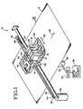
- Fig. 1 shows a portion of a color inkjet marking apparatus 10.
- the apparatus 10 includes multiple inkjet pen 14, 16, 18, 20 which print characters, symbols, graphics or other imagery and markings onto a media sheet 12.
- the pens 14-20 are shuttled along a scanning axis 26, while the media sheet 12 is moved along a media path in a media direction 28.
- the scanning axis 26 is referred to herein as a horizontal axis 26 given the same part number.
- the media direction 28 corresponds to a vertical axis 28 given the same part number.
- the axes 26, 28 may be oppositely named. Other naming conventions also may be used.
- the media sheet 12 is moved by rollers 30 on an axle 32, which in turn are driven by gears 34 and a motor 36.
- the pens 14-20 are carried in a carriage 22 which moves along a carriage rod 24.
- a drive belt 38 coupled to the carriage 22 exerts a drive force which moves the carriage 22.
- a drive motor 40 generates the drive force.
- the motor 40 turns a drive pulley 42 on a drive shaft 44.
- the drive belt 38 runs along the drive pulley 42 and an idler pulley 46 coupled to an idler spring 48.
- Carriage position and media sheet position are monitored by a processor 52.
- Carriage position is derived from a signal from a digital encoder 56 indicative of drive belt position.
- Media sheet position is determined from signals marking the passing of a media sheet at a known point and from a signal from a digital encoder.
- the motor 36 includes the digital encoder for tracking the roller 30 position.
- An optical sensor 54 detects the passing edge of the media sheet 12.
- Another optical sensor 58 moves with the carriage 22 along the carriage rod 24 for use in calibrating image registration.
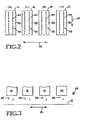
- the inkjet pens 14-20 store ink of different colors, e.g., black, cyan, magenta and yellow. As the carriage 22 and media sheet 12 translate relative to each other, the pens 14-20 scan the media sheet along the horizontal axis 26 and vertical axis 28. Referring to Fig. 2, each pen 14-20 includes a printhead 60 having an array 62 of nozzles 64. The nozzles 64 eject ink drops 66 onto the media sheet 12 as shown in Fig. 3. The number of drops, the density of the drops and the ink color of the drops determine the colors perceived by a viewer in a printed image or marking. Accordingly, to achieve accurate printing of desired colors it is important that the ink drops be placed precisely in desired positions.
- ink drops be placed precisely in desired positions.
- One challenge to such positioning is misalignment of the pens 14-20 in the carriage 22. Once the pens are locked into the carriage 22 there position is generally fixed. However, such position may vary when a pen is removed or replaced. To assure high quality printing, the registration of dots from the various printheads 60 of pens 14-20 are calibrated so that the printheads 60 are in a known position relative to each other.
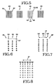
- Fig. 4 shows multiple sets 70, 72, 74, 78, 80 of test patterns used for calibrating registration of the printheads 60 of the inkjet pens 14-20.
- each set includes 7 test patterns 81-87, although the number may vary.
- one printhead is taken to be a reference.
- the other printheads are calibrated relative to the position of such printhead.
- Registration of each of the non-reference printhead from corresponding pens 14, 16 and 20 is calibrated along both the horizontal axis 26 and the vertical axis 28.
- Fig. 4 shows six sets of test patterns.
- set 70 is for calibrating the black pen 14 printhead relative to the horizontal axis.
- Set 72 is for calibrating the black pen 14 printhead relative to the vertical axis.
- Set 74 is for calibrating the cyan pen 16 printhead relative to the horizontal axis.
- Set 76 is for calibrating the cyan pen 16 printhead relative to the vertical axis.
- Set 78 is for calibrating the yellow pen 20 printhead relative to the horizontal axis.
- Set 80 is for calibrating the yellow pen 20 printhead relative to the vertical axis.
- the ordering of the sets may vary.
- Each set 70-80 of test patterns is arranged along the horizontal axis 26, although in other embodiments they may be aligned along the vertical axis 28. Further, in some embodiments the horizontal calibration sets 70, 74, 78 may be aligned along one of the axes 26, 28 while the vertical calibration sets 72, 76, 80 are aligned on the other of the axes 26, 28.
- Each set 70, 74, 78 for horizontal calibration includes a plurality of vertical bars spaced apart along the horizontal axis 26.
- each set 72, 76, 80 for vertical calibration includes a plurality of horizontal bars spaced apart along the vertical axis 28. Although bars are shown and described, circles, diamonds, squares or other shapes may be used.
- Each test pattern 70-80 includes two portions. Each portion is of the same size and shape. One portion is formed of ink drops from the reference pen 18 printhead, while the other portion is formed of ink drops from the printhead being calibrated.
- sets 70, 72 include magenta ink drops from the reference pen 18 printhead and black ink drops from the pen 14 printhead.
- Sets 74, 76 include magenta ink drops from the reference pen 18 printhead and cyan ink drops from the pen 16 printhead.
- Sets 78, 80 include magenta ink drops from the reference pen 18 printhead and yellow ink drops from the pen 20 printhead.
- Fig. 5 shows 4 test patterns 83-86 of a given set of test patterns for a sample process for calibrating cyan ink pen 16 printhead for the horizontal axis 26.
- each test pattern includes a plurality of vertical bars horizontally spaced.
- the reference ink bars 90 are drawn as solid lines and the cyan bars 92 are drawn as dashed lines. From test pattern 83 to test pattern 86 the registration of the cyan bars 92 is shifting left on the page of the drawing. In test pattern 85 the cyan bars 92 and reference bars 90 overlap.
- Fig. 6 shows a magnified view of a portion of the sample test pattern 85 of Fig. 5 having the desired registration along axis 27 (e.g., one of axes 26, 28).
- Three bars 94, 96, 98 are shown.
- Each bar is shown as a plurality of ink drops.
- a reference color ink drop is depicted with an 'x', while the printhead under test ink drops (e.g., cyan) are depicted with an 'o'.
- the dots of the respective printhead also overlap for the desired registration.
- every other nozzle is used in the test pattern to draw the bars 90, 92.
- Fig. 7 shows the example where the bars 90, 92 overlap to define the respective bars 94', 96', 98' of a test pattern 85' having the desired registration along the axis 27 being calibrated.
- Fig. 6 For the desired registration the bars from the reference pen 18 printhead and the bars from the pen under test overly each other.
- the dots of the two colors also overly each other.
- the dots align along the non-calibrating axis irrespective of whether the dots themselves overlap, (e.g., for horizontal calibration, the dots align vertically even if they do not overlap).
- Fig. 8 shows a magnified view of a portion of a sample test pattern 83 having poor registration. In a poor registration the bars from the reference pen 18 printhead and the bars from the printhead under test do not overlap.
- Each bar 90, 92 is shown as a plurality of ink drops.
- test pattern 85 is shown to have desired registration and test pattern 83 is shown to have poor registration.
- the test pattern of a given set of test patterns having the best registration need not be pattern 85 and may differ from one set to the next.
- test pattern 83 need not be a poor test pattern.
- the reflectance of the media sheet is sensed for each test pattern 81-87 in a set of test patterns.
- the test pattern having the highest reflectance is the test patten having the best degree of overlapping, and thus the best registration.
- each bar of a given color ink in a test pattern has the same number of dots in width.
- the bars from a given pen are spaced apart by at least two dot widths.
- each bar of a given color ink is one dot wide and spaced five dots apart.
- the width of a bar is the same for each printhead.
- the spacing between bars of a given color is the same for each color ink. What varies is the registration of the bars of one color ink relative to the bars of the reference color ink. A best registration is selected for each set of test patterns, and thus, for each printhead under test in each of the axes 26, 28. The best registration is that corresponding to the test pattern having the highest reflectance within a set of test patterns.
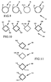
- Fig. 9 shows a plurality 70 of test patterns 72-78 according to another embodiment of this invention.
- Each test pattern includes two portions 71, 73.
- one portion 71 is printed from one inkjet printhead, while the other portion 73 is printed from another inkjet printhead.
- One inkjet printhead serves as a reference printhead.
- the other inkjet printhead is a printhead being calibrated.
- the image registration for the calibrated printhead is varied for each test pattern 72-78. Such image registration may be varied among one two printing axes.
- each test pattern may include more than two portions with each portion being printed by a different printhead. Image registration of at least one printhead is changed for each test pattern. At least one other pen serves as a reference printhead in which its image registration is the same for each test pattern.
- Each portion 71, 73 has the same size and shape.
- Each test pattern 72-78 is generally circular.
- Fig. 10 shows another plurality 100 of test patterns 102-108 in which each portion 101, 103 is diamond shaped. Although, test patterns have been described and illustrated to include one or more lines, circles or diamonds, other shapes also may be used.
- a set of test patterns are printed.
- the set includes a plurality of test patterns.
- Each test patten includes one or more bars, circles, diamonds or other shapes.
- the bars are spaced apart along an axis of calibration.
- the bars are elongated in the direction perpendicular to the axis under calibration.
- the orientation of the shape may be the same regardless of the calibration axis.
- each test pattern includes a plurality of bars of the printhead under test and the reference printhead.
- Optical sensor 58 then scans the set of test patterns to sample the reflectance of each test pattern.
- the processor 52 receives the sensor samples are derives a value indicative of reflectance for a scanned test pattern. A value is derived for each test pattern in the set.
- the processor identifies which test pattern has the highest reflectance.
- Such test pattern has the most overlapping of bars of the two colors (i.e., the ink colors of the printhead under test and of the reference printhead), and thus corresponds to the best registration for the axis calibrated.
- the registration used for such selected test pattern is the registration selected for the printhead under test for the axis calibrated.
- Another set of test patterns then is printed for calibrating relative to the other axis 26, 28. The process is repeated to calibrate registration of each printhead relative to a reference printhead.
- One of the four pens 14-10 is selected as the reference printhead as described above.
- the timing or assignment of nozzles to eject ink drops is changed.
- the registration is changed by one nozzle width from one test pattern to the next test pattern in a given set of test patterns.
- the unit of change among test patterns may vary and need not be of constant increments.
- more than two colors of ink may be used in one or more sets of test patterns of test patterns so that fewer sets of test patterns are printed to calibrate registration.
- the registration of one or more printheads is varied while the registration of at least one printhead is held constant for a given set of test patterns.
- sets 74, 76 then are used to calibrate the desired registration along the respective axes for the remaining printhead.
- sets 74, 76 include bars printed from the remaining printhead not included in sets 70, 72 and at least one other printhead.
- Sets 74, 76 may use ink from 2, 3 or 4 printheads. Only the registration of the remaining printhead is changed from pattern to pattern in sets 74, 76.
- the patterns of set 74 are scanned. The registration corresponding to the pattern with the highest reflectance is used for such remaining printhead. Such registration is the calibrated registration along the axis calibrated using set 74.
- the patterns of set 76 are scanned. The registration corresponding to the pattern with the highest reflectance is used for such remaining pen. Such registration is the calibrated registration along the axis calibrated using set 76.
- an operator inspects the test patterns, rather than an optical sensor.
- an operator enters a pattern number to identify which pattern has the best alignment.
- the reference printhead ejects black ink.
- a method for calibrating a most desirable paper advancement distance is implemented by printing a set of test patterns 105, 107, 109, 111 onto a media sheet.
- Each test pattern includes a first portion and a second portion which have a common pattern, size and shape. The portions are generally overlapping.
- a first portion 102 of test pattern 105 is printed using a first subset of nozzles of an inkjet printhead 60.
- the media sheet is advanced by a media advancement distance.
- a second portion 104 of test pattern 105 is printed with a second subset of nozzles differing from the first subset.
- the second subset is picked so as to be spaced from the first subset approximately by media advancement distance. Accordingly, the second portion 104 overlaps the first portion 102.
- test pattern 107 with generally overlapping test pattern portions 106 and 108.
- the portion 106 is printed using the first subset of nozzles while portion 108 is printed using the second subset of nozzles.
- the media advancement distance is different than the distance moved between printing the portions 102 and 104 of test pattern 105.
- the overlapping of test pattern 107 portions 106 and 108 differs from the overlapping of test pattern 105 portions 102 and 104. More particularly the amount of blank space, and thus the reflectance among the test patterns 105, 107 varies.
- the media sheet then is advanced again to a clean area of the media sheet and the steps then are repeated to achieve test pattern 109 with generally overlapping test pattern portions 110 and 112.
- the portion 110 is printed using the first subset of nozzles while portion 112 is printed using the second subset of nozzles.
- the media advancement distance is different than the distance moved between printing the portions 102 and 104 of test pattern 105, and between printing the portions 106 and 108 of test pattern 107.
- the overlapping of test pattern 109 portions 110 and 112 differs from the overlapping in test pattern 105 and in test pattern 107. More particularly the amount of blank space, and thus the reflectance among the test patterns 105, 107 and 109 varies.
- test pattern 111 with generally overlapping test pattern portions 114 and 116.
- the portion 114 is printed using the first subset of nozzles while portion 116 is printed using the second subset of nozzles.
- the media advancement distance is different than the distance moved between printing the portions of test patterns 105, 107 and 109.
- the overlapping of test pattern 111 portions 114 and 116 differs from the overlapping in test patterns 105, 107 and 109. More particularly the amount of blank space, and thus the reflectance among the test patterns 105, 107 and 109 varies. Note that the spacing between test pattern portions in a given test pattern is exaggerated for purposes of illustration.
- test pattern portion within a given test pattern is the same.
- the various test patterns 105, 107, 109 and 111 may vary in a given embodiment.
- Optical sensor 58 then scans the set of test patterns 105, 107, 109, 111 to sample the reflectance of each test pattern.
- the processor 52 receives the sensor samples are derives a value indicative of reflectance for a scanned test pattern. A value is derived for each test pattern.
- the processor identifies which test pattern has the highest reflectance. Such test pattern has the most closely aligned overlapping portions, and corresponds to a best paper advancement distance. The paper advancement distance used for such selected test pattern is the paper advancement distance selected.
- the paper advance can be calibrated according to the method described above or by an alternative method.
- the paper advance can be measured in terms of the number of nozzles moved and by which nozzles line up.
- the paper advance is altered by changing the paper advance distance in proportion to the measured nozzle distance.
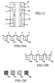
- the paper advance is calibrated together with printhead nozzle array length as described below with regard to Figs. 14A-C.
- a printhead 60 includes nozzles 64 allocated among four different portions 122, 124, 126, 128 to be calibrated. Such portions are referred to as portions a, b, c and d.
- inter-column alignment is calibrated.
- printhead array length is calibrated.
- test patterns are printed using different parts of the printhead. Deviation from nominal offsets in the nozzle positions of a given portion a, b, c or d are determined from the degree of overlap among portions of a test pattern.
- the test pattern preferably is a set of regularly spaced lines. However, other shaped may be used such as diamond patterns, circular patterns, square pattern and other regular or irregular shaped patterns.
- a first portion of each of multiple test patterns 130, 132, 134, 136 is printed using nozzles from printhead portion a as shown in Fig. 13a. Each portion is spaced from the next portion by a distance x.
- a second portion of each of the multiple test patterns is printed using nozzles from portion b. Note that the first portion and second portion of each test pattern may be printed on the same scan of the inkjet pen across the media sheet. The first portion and the second portion of each test pattern are identical. The second portions, however, are printed at a spacing y between each test portion.
- the nominal inter-column distance between the nozzles in printhead portion a and printhead portion b are to be accounted for in determining the starting position of pattern 130.
- the different patterns will be printed with offsets that are multiples of the x-y distance.
- each test pattern 130-136 will have a different reflectance as some dots are superimposed.
- the inter-column offset distance used to achieve the test pattern having the highest reflectance (i.e., most overlay) is added to the nominal inter-column distance to determine the actual inter-column distance.
- a first portion of each of multiple test patterns 140, 142, 144, 146 is printed using nozzles from printhead portion a as shown in Fig. 14a.
- the media sheet is advanced by a nominal distance equivalent to the distance between the centroids of the nozzle groups to be aligned.
- a second portion of each of the multiple test patterns is printed using nozzles from portion c.
- the first portion and the second portion of each test pattern are identical.
- the second portions are offset vertically by a small amount (e.g., one nozzle spacing).
- each test pattern 140-146 will have a different reflectance as some dots are superimposed.
- the test pattern having the highest reflectance corresponds to the array length variation between portions a and c for a given paper advance increment. In effect array length and paper advance are calibrated together.
- a calibration process is performed.
- multiple test patterns are printed. Referring to Fig. 15a a first portion of each one of multiple test patterns 150, 152, 154, 156 is printed while scanning the inkjet printhead 60 across the media sheet in a first direction 148. The spacing between each test pattern is the same. At another step a second portion of each of the test patterns is printed while scanning back across the media sheet in the opposite direction 149. The spacing between each second portion, however varies. Thus, the registration of the first portion and second portion pf each test pattern 150-156 varies.
- the test pattern of 150-156 having the highest reflectance corresponds to a calibration spacing to be used to achieve bidirectional printhead alignment.
- the method may be implemented conversely in which printheads attempt to print completely out of phase.
- the test pattern with the minimal reflectance would then corresponds to the best alignment.
- the test patterns can alternately be evaluated for the consistency of the reflectance across the pattern, where the most consistent reflectance across the pattern indicates the best alignment.
Description
- This invention relates generally to printers, plotters, and marking devices, and more particularly, to inkjet printers, plotters and marking devices having multiple printheads for multi-color printing.
- Inkjet marking devices typically include one or more inkjet pens mounted on a carriage. Each pen includes a printhead having a plurality of inkjet nozzles. During printing, the carriage moves across a media sheet while the nozzles discharge ink drops. The timing of the ink drop ejection is controlled to precisely place the drops at desired locations.
- A typical multi-color inkjet marking device includes two or more inkjet pens with respective printheads. One pen stores black ink, while the others store ink of one or more colors, (e.g., cyan, magenta or yellow). The four inks represent four base colors which are applied to a media sheet to derive any of multiple colors.
- The pens typically are mounted in stalls within the carriage. To achieve desired print quality the ink colors need to be precisely placed at desired locations on the media sheet. To do so the pen printheads are to be maintained in precise alignment. The pens typically are loaded and replaced periodically by the end user. As a result, mechanical misalignment is likely to occur. Mechanical misalignment results in offsets of one or more pens' nozzles relative to the other pens' nozzles. This misalignment manifests as a misregistration of the dots forming a print symbol, image, or graphic representation. Other sources of misalignment also may occur due to the speed of motion of the carriage, the curvature of the platen and the spray of the nozzles.
- One conventional approach for aligning the pens is to use an optical drop detector. This technique is described in U.S. Patent No. 4,922,270, issued May 1, 1990 to Cobbs et al., entitled "Inter Pen Offset Determination and Compensation in Multi-Pen Thermal Ink Jet Printing Systems." The optical drop detectors detect the position of each ink drop as it leaves the pen. The system then calculates the point of impact of the drop on the print media. Unfortunately the actual impact point often differs substantially from the calculated impact point due to angularity and mechanical tolerances in the system. Angularity results from the movement of the pen in the scan axis as ink is being ejected. There is a delay between the time that the drop of ink is ejected and the time that the drop impacts the media. This flight time delay causes the drop to traverse an angular path toward the media. Inaccurate correction for this delay distorts the image.
- U.S. Patent No. 5,289,208 issued February 22, 1994 of Robert D. Haselby entitled "Automatic Print Cartridge Alignment Sensor System" discloses a technique in which an optical sensor detects the position of test line segments. Vertical alignment is achieved by printing a plurality of non-overlapping horizontal test line segments. A quad photodiode detector detects the vertical positions of the horizontal test line segments relative to a fixed reference. Horizontal alignment is achieved by printing a plurality of non-overlapping vertical test line segments in a vertical direction. If properly aligned the line segments connect to form a straight line (e.g., for printing 2 line segments the line is 2 line segments long). If misaligned, the line segments form an angled line (e.g., for printing 2 line segments the line is 2 line segments long). A quad photodiode detector detects the horizontal positions of the vertical test line segments to determine if the segments are aligned.
- U.S. Patent No. 5,451,990 discloses a reference pattern for use in performing image registration for multiple inkjet cartridges. The reference pattern includes four test patterns. One test pattern is generated along the scan axis to exercise the pens. It includes an individual section for each color. A second test pattern is used to test for pen offset due to speed and curvature. The second pattern is a bidirectional test pattern in which the cartridge is moved at differing speeds in each direction. A pattern is generated for each color. A third pattern is generated by causing each pen to print a plurality of horizontally spaced vertical bars. The fourth patten includes five columns of vertically spaced horizontal bars. Each column has three sections. The first section in each column is generated using one color (e.g., cyan). In the second section the same color (cyan) is used in columns one and five. The other colors are used respectively in columns 2-4 (e.g., magenta in column 2; yellow in column 3; black in column 4). In the third section of each column, the first color (cyan) is used. Note that the colors do not overlap in any of the patterns.
- The invention provides a method according to claim 1, and a system according to claim 6. Preferred method embodiments are defined in claims 2 to 5.
- One advantage of the invention is that by overlaying the inks of differing color a smaller area is used to perform color registration and printhead alignment. As a result, the registration process is faster. Another advantage is that the proper alignment may be identified visually by an operator. Another advantage is that all nozzles of a printhead may participate in the calibration process. This results in a more reliable alignment method which provides effective results even when one or more individual nozzles fail. These and other aspects and advantages of the invention will be better understood by reference to the following detailed description taken in conjunction with the accompanying drawings.
-
- Fig. 1 is a perspective view of a portion of an inkjet printing apparatus according to an embodiment of this invention;
- Fig. 2 is a diagram of printheads for the inkjet pens of Fig. 1;
- Fig. 3 is a diagram of ink drop ejection from the pens of Fig. 1 onto a media sheet;
- Fig. 4 is a diagram depicting multiple sets of test patterns according to an embodiment of this invention;
- Fig. 5 is a magnified view of a portion of a set of test patterns of Fig. 4;
- Fig. 6 is a magnified view of a portion of a test pattern of Fig. 5 having desired registration according to one embodiment of this invention;
- Fig. 7 is a magnified view of a portion of a test pattern of Fig. 5 having desired registration according to an alternative embodiment of this invention;
- Fig. 8 is a magnified view of a portion of a test pattern of Fig. 5 having poor registration;
- Fig. 9 is a diagram of test patterns according to another embodiment of this invention;
- Fig. 10 is a diagram of test patterns according to another embodiment of this invention;
- Fig. 11 is a diagram of test patterns for a method of calibrating paper advancement distance;
- Fig. 12 is a diagram of a printhead nozzle layout having multiple printhead portions to be calibrated;
- Figs. 13a-13c are diagrams of a set of test patterns for calibrating inter-column printhead alignment;
- Figs. 14a-14c are diagrams of a set of test patterns for calibrating array length variation;
- Figs. 15a-15b are diagrams of a set of test patterns for calibrating bidirectional printing alignment.
- Fig. 1 shows a portion of a color
inkjet marking apparatus 10. Theapparatus 10 includesmultiple inkjet pen media sheet 12. The pens 14-20 are shuttled along a scanningaxis 26, while themedia sheet 12 is moved along a media path in amedia direction 28. The scanningaxis 26 is referred to herein as ahorizontal axis 26 given the same part number. Themedia direction 28 corresponds to avertical axis 28 given the same part number. Theaxes media sheet 12 is moved byrollers 30 on anaxle 32, which in turn are driven bygears 34 and amotor 36. The pens 14-20 are carried in acarriage 22 which moves along acarriage rod 24. Adrive belt 38 coupled to thecarriage 22 exerts a drive force which moves thecarriage 22. Adrive motor 40 generates the drive force. Themotor 40 turns adrive pulley 42 on adrive shaft 44. Thedrive belt 38 runs along thedrive pulley 42 and anidler pulley 46 coupled to anidler spring 48. - Carriage position and media sheet position are monitored by a
processor 52. Carriage position is derived from a signal from adigital encoder 56 indicative of drive belt position. Media sheet position is determined from signals marking the passing of a media sheet at a known point and from a signal from a digital encoder. Themotor 36 includes the digital encoder for tracking theroller 30 position. Anoptical sensor 54 detects the passing edge of themedia sheet 12. Anotheroptical sensor 58 moves with thecarriage 22 along thecarriage rod 24 for use in calibrating image registration. - The inkjet pens 14-20 store ink of different colors, e.g., black, cyan, magenta and yellow. As the
carriage 22 andmedia sheet 12 translate relative to each other, the pens 14-20 scan the media sheet along thehorizontal axis 26 andvertical axis 28. Referring to Fig. 2, each pen 14-20 includes aprinthead 60 having anarray 62 ofnozzles 64. Thenozzles 64 eject ink drops 66 onto themedia sheet 12 as shown in Fig. 3. The number of drops, the density of the drops and the ink color of the drops determine the colors perceived by a viewer in a printed image or marking. Accordingly, to achieve accurate printing of desired colors it is important that the ink drops be placed precisely in desired positions. One challenge to such positioning is misalignment of the pens 14-20 in thecarriage 22. Once the pens are locked into thecarriage 22 there position is generally fixed. However, such position may vary when a pen is removed or replaced. To assure high quality printing, the registration of dots from thevarious printheads 60 of pens 14-20 are calibrated so that theprintheads 60 are in a known position relative to each other. - Fig. 4 shows
multiple sets printheads 60 of the inkjet pens 14-20. In the embodiment illustrated each set includes 7 test patterns 81-87, although the number may vary. In a preferred embodiment one printhead is taken to be a reference. The other printheads are calibrated relative to the position of such printhead. Registration of each of the non-reference printhead from correspondingpens horizontal axis 26 and thevertical axis 28. There is a set of test patterns for each calibration of each non-reference printhead. Thus, Fig. 4 shows six sets of test patterns. For example, set 70 is for calibrating theblack pen 14 printhead relative to the horizontal axis.Set 72 is for calibrating theblack pen 14 printhead relative to the vertical axis.Set 74 is for calibrating thecyan pen 16 printhead relative to the horizontal axis.Set 76 is for calibrating thecyan pen 16 printhead relative to the vertical axis.Set 78 is for calibrating theyellow pen 20 printhead relative to the horizontal axis.Set 80 is for calibrating theyellow pen 20 printhead relative to the vertical axis. The ordering of the sets may vary. Each set 70-80 of test patterns is arranged along thehorizontal axis 26, although in other embodiments they may be aligned along thevertical axis 28. Further, in some embodiments the horizontal calibration sets 70, 74, 78 may be aligned along one of theaxes axes - Each set 70, 74, 78 for horizontal calibration includes a plurality of vertical bars spaced apart along the
horizontal axis 26. Conversely, each set 72, 76, 80 for vertical calibration includes a plurality of horizontal bars spaced apart along thevertical axis 28. Although bars are shown and described, circles, diamonds, squares or other shapes may be used. Each test pattern 70-80 includes two portions. Each portion is of the same size and shape. One portion is formed of ink drops from thereference pen 18 printhead, while the other portion is formed of ink drops from the printhead being calibrated. Thus sets 70, 72 include magenta ink drops from thereference pen 18 printhead and black ink drops from thepen 14 printhead.Sets reference pen 18 printhead and cyan ink drops from thepen 16 printhead.Sets reference pen 18 printhead and yellow ink drops from thepen 20 printhead. - Within each given set 70-80 of test patterns, the registration of the
reference pen 18 printhead is the same for each test pattern 81-87, while the registration of the pen printhead under test varies for each test pattern 81-87. Fig. 5 shows 4 test patterns 83-86 of a given set of test patterns for a sample process for calibratingcyan ink pen 16 printhead for thehorizontal axis 26. As described above each test pattern includes a plurality of vertical bars horizontally spaced. For purposes of illustration the reference ink bars 90 are drawn as solid lines and the cyan bars 92 are drawn as dashed lines. Fromtest pattern 83 to testpattern 86 the registration of the cyan bars 92 is shifting left on the page of the drawing. Intest pattern 85 the cyan bars 92 andreference bars 90 overlap. - Fig. 6 shows a magnified view of a portion of the
sample test pattern 85 of Fig. 5 having the desired registration along axis 27 (e.g., one ofaxes 26, 28). Threebars bars bars axis 27 being calibrated. - For the desired registration the bars from the
reference pen 18 printhead and the bars from the pen under test overly each other. In the Fig. 6 embodiment the dots of the two colors also overly each other. In the Fig. 7 embodiment the dots align along the non-calibrating axis irrespective of whether the dots themselves overlap, (e.g., for horizontal calibration, the dots align vertically even if they do not overlap). Fig. 8 shows a magnified view of a portion of asample test pattern 83 having poor registration. In a poor registration the bars from thereference pen 18 printhead and the bars from the printhead under test do not overlap. Eachbar test pattern 85 is shown to have desired registration andtest pattern 83 is shown to have poor registration. The test pattern of a given set of test patterns having the best registration need not bepattern 85 and may differ from one set to the next. Similarly,test pattern 83 need not be a poor test pattern. These were represented as having desired registration and poor registration merely for purposes of illustration and description. Although Figs. 5-8 depict dots for a test pattern having vertical lines, similar alignment and misalignment occurs for the test patterns formed by horizontal lines. - It is significant that the bars of differing color ink drops overlap in the desired registration and do not overlap in the poor registration. As the registration varies from desired to poor the degree of overlap decreases. As the amount of overlap decreases, the amount of background media sheet covered with ink increases. According to an aspect of this invention, the reflectance of the media sheet is sensed for each test pattern 81-87 in a set of test patterns. The test pattern having the highest reflectance is the test patten having the best degree of overlapping, and thus the best registration.
- In a preferred embodiment each bar of a given color ink in a test pattern has the same number of dots in width. The bars from a given pen are spaced apart by at least two dot widths. In an exemplary embodiment, each bar of a given color ink is one dot wide and spaced five dots apart. The width of a bar is the same for each printhead. The spacing between bars of a given color is the same for each color ink. What varies is the registration of the bars of one color ink relative to the bars of the reference color ink. A best registration is selected for each set of test patterns, and thus, for each printhead under test in each of the
axes - Fig. 9 shows a
plurality 70 of test patterns 72-78 according to another embodiment of this invention. Each test pattern includes twoportions portion 71 is printed from one inkjet printhead, while theother portion 73 is printed from another inkjet printhead. One inkjet printhead serves as a reference printhead. The other inkjet printhead is a printhead being calibrated. The image registration for the calibrated printhead is varied for each test pattern 72-78. Such image registration may be varied among one two printing axes. In another embodiment each test pattern may include more than two portions with each portion being printed by a different printhead. Image registration of at least one printhead is changed for each test pattern. At least one other pen serves as a reference printhead in which its image registration is the same for each test pattern. - Each
portion plurality 100 of test patterns 102-108 in which eachportion - To calibrate registration of a given printhead relative to a given
axis 26, 28 a set of test patterns are printed. The set includes a plurality of test patterns. Each test patten includes one or more bars, circles, diamonds or other shapes. For a test pattern formed by a plurality of bars, the bars are spaced apart along an axis of calibration. The bars are elongated in the direction perpendicular to the axis under calibration. For circles or diamonds having symmetry along either calibration axis, the orientation of the shape may be the same regardless of the calibration axis. - With regard to the test pattern of bars, to calibrate the
black ink pen 14 printhead for the horizontal axis a plurality of vertical black bars are printed with horizontal spacing in each test pattern of the set. A similar plurality of bars are printed with the reference printhead for each given test pattern. Thus, each test pattern includes a plurality of bars of the printhead under test and the reference printhead.Optical sensor 58 then scans the set of test patterns to sample the reflectance of each test pattern. Theprocessor 52 receives the sensor samples are derives a value indicative of reflectance for a scanned test pattern. A value is derived for each test pattern in the set. The processor identifies which test pattern has the highest reflectance. Such test pattern has the most overlapping of bars of the two colors (i.e., the ink colors of the printhead under test and of the reference printhead), and thus corresponds to the best registration for the axis calibrated. The registration used for such selected test pattern is the registration selected for the printhead under test for the axis calibrated. Another set of test patterns then is printed for calibrating relative to theother axis - To vary the registration of the printhead under test from one test pattern to the next the timing or assignment of nozzles to eject ink drops is changed. According to one embodiment the registration is changed by one nozzle width from one test pattern to the next test pattern in a given set of test patterns. The unit of change among test patterns however may vary and need not be of constant increments.
- There are many variables which may change from embodiment to embodiment, such as the number of bars of a given color ink per test pattern, the spacing between bars, the thickness of each bar, the dot density of each bar, and the change in registration from one pattern to the next. Alignment is achievable for spatial resolutions as fine as 0.25 dot rows.
- In an alternative embodiment, more than two colors of ink may be used in one or more sets of test patterns of test patterns so that fewer sets of test patterns are printed to calibrate registration. In such an embodiment the registration of one or more printheads is varied while the registration of at least one printhead is held constant for a given set of test patterns. Consider an example in which four sets 70, 72, 74, 76 are printed.
Sets sets Sets sets set 74 are scanned. The registration corresponding to the pattern with the highest reflectance is used for such remaining printhead. Such registration is the calibrated registration along the axis calibrated usingset 74. Similarly, the patterns ofset 76 are scanned. The registration corresponding to the pattern with the highest reflectance is used for such remaining pen. Such registration is the calibrated registration along the axis calibrated usingset 76. - In another embodiment an operator inspects the test patterns, rather than an optical sensor. In one example, an operator enters a pattern number to identify which pattern has the best alignment.
- In a best mode multi-color printing embodiment, the reference printhead ejects black ink.
- Referring to Fig. 11, a method for calibrating a most desirable paper advancement distance is implemented by printing a set of
test patterns first portion 102 oftest pattern 105 is printed using a first subset of nozzles of aninkjet printhead 60. At another step, the media sheet is advanced by a media advancement distance. Then asecond portion 104 oftest pattern 105 is printed with a second subset of nozzles differing from the first subset. The second subset is picked so as to be spaced from the first subset approximately by media advancement distance. Accordingly, thesecond portion 104 overlaps thefirst portion 102. - Next, the media is advanced to a clean area of the media sheet and the steps then are repeated to achieve
test pattern 107 with generally overlappingtest pattern portions portion 106 is printed using the first subset of nozzles whileportion 108 is printed using the second subset of nozzles. Fortest patterns 107, the media advancement distance is different than the distance moved between printing theportions test pattern 105. Thus, the overlapping oftest pattern 107portions test pattern 105portions test patterns - The media sheet then is advanced again to a clean area of the media sheet and the steps then are repeated to achieve
test pattern 109 with generally overlappingtest pattern portions portion 110 is printed using the first subset of nozzles whileportion 112 is printed using the second subset of nozzles. Fortest pattern 109, the media advancement distance is different than the distance moved between printing theportions test pattern 105, and between printing theportions test pattern 107. Thus, the overlapping oftest pattern 109portions test pattern 105 and intest pattern 107. More particularly the amount of blank space, and thus the reflectance among thetest patterns - The media sheet then is advanced again to a clean area of the media sheet and the steps then are repeated to achieve
test pattern 111 with generally overlappingtest pattern portions portion 114 is printed using the first subset of nozzles whileportion 116 is printed using the second subset of nozzles. Fortest pattern 111, the media advancement distance is different than the distance moved between printing the portions oftest patterns test pattern 111portions test patterns test patterns various test patterns -
Optical sensor 58 then scans the set oftest patterns processor 52 receives the sensor samples are derives a value indicative of reflectance for a scanned test pattern. A value is derived for each test pattern. The processor identifies which test pattern has the highest reflectance. Such test pattern has the most closely aligned overlapping portions, and corresponds to a best paper advancement distance. The paper advancement distance used for such selected test pattern is the paper advancement distance selected. - For a printing apparatus in which the paper advancement has a consistent paper advance error, the paper advance can be calibrated according to the method described above or by an alternative method. In the alternative method, the paper advance can be measured in terms of the number of nozzles moved and by which nozzles line up. The paper advance is altered by changing the paper advance distance in proportion to the measured nozzle distance. According to the alternative method, the paper advance is calibrated together with printhead nozzle array length as described below with regard to Figs. 14A-C.
- Referring to Fig. 12, a
printhead 60 includesnozzles 64 allocated among fourdifferent portions - For the inter-column alignment calibration method, a first portion of each of
multiple test patterns pattern 130. By using a spacing y distinct from x, the different patterns will be printed with offsets that are multiples of the x-y distance. Referring to Fig. 13c, each test pattern 130-136 will have a different reflectance as some dots are superimposed. The inter-column offset distance used to achieve the test pattern having the highest reflectance (i.e., most overlay) is added to the nominal inter-column distance to determine the actual inter-column distance. - For the printhead array length calibration method, a first portion of each of
multiple test patterns - To calibrate image registration variations for printing while scanning in one direction across a media sheet versus printing while scanning in the opposite direction across the media sheet, a calibration process is performed. As with the other calibration methods described above, multiple test patterns are printed. Referring to Fig. 15a a first portion of each one of
multiple test patterns inkjet printhead 60 across the media sheet in afirst direction 148. The spacing between each test pattern is the same. At another step a second portion of each of the test patterns is printed while scanning back across the media sheet in theopposite direction 149. The spacing between each second portion, however varies. Thus, the registration of the first portion and second portion pf each test pattern 150-156 varies. The test pattern of 150-156 having the highest reflectance (e.g., most background space) corresponds to a calibration spacing to be used to achieve bidirectional printhead alignment. - The method may be implemented conversely in which printheads attempt to print completely out of phase. The test pattern with the minimal reflectance would then corresponds to the best alignment. For some alternate test patterns, such as concentric circles or diamonds, the test patterns can alternately be evaluated for the consistency of the reflectance across the pattern, where the most consistent reflectance across the pattern indicates the best alignment.
Claims (6)
- A method for calibrating image registration for two inkjet printheads (60), each printhead including a plurality of inkjet nozzles (64), the method comprising the steps of:printing a first plurality of test patterns (81-87 / 72-78 / 102-108) onto a media sheet, each one test pattern of the plurality of test patterns including a first portion (90/71/101) printed with a first inkjet printhead and a second portion (92/73/103) printed with a second inkjet printhead, wherein the first portion and second portion are of the same shape, wherein image registration of one of said two inkjet printheads is varied among each one of the plurality of test patterns; andinspecting the plurality of test patterns;selecting the image registration corresponding to one of the plurality of test pattern having the most unprinted background area.
- The method of claim 1, wherein during the step of printing the plurality of test patterns, image registration of said one printhead is varied for each one test pattern by changing a selection of nozzles of said one printhead used in printing said one test pattern.
- The method of claims 1 or 2, in which the step of inspecting comprises the step of sensing the reflectance of each one of the plurality of test patterns, and wherein the step of selecting comprises selecting the image registration corresponding to the test pattern having the highest reflectance.
- The method of claims 1, 2, 3 or 4 in which the first inkjet printhead prints ink of a differing color than the second inkjet printhead.
- The method of claim 4, wherein each one of the first plurality of test patterns includes a plurality of horizontally-spaced vertical bars (90, 92) and is formed by printing ink drops from at least two of the plurality of inkjet printheads, wherein horizontal registration of at least one of said two of the plurality of inkjet printheads is varied among each one of the first plurality of test patterns, the method further comprising:printing a second plurality (72) of test patterns (81-87), wherein each one of the second plurality of test patterns includes a plurality of vertically-spaced horizontal bars and is formed by printing ink drops from at least two of the plurality of inkjet printheads, wherein vertical registration of at least one of said two of the plurality of inkjet printheads is varied among each one of the second plurality of test patterns; andwherein inspecting the plurality of test patterns comprises inspecting the first and second plurality of test patterns.
- An image registration system for a multi-color inkjet marking apparatus (10), comprising:a plurality of inkjet printheads (60), each printhead of the plurality of printheads having a plurality of nozzles (64) adapted to discharge ink in response to a corresponding electrical signal;a carriage (22) retaining the plurality of inkjet printheads, the carriage moving along a first axis (26);rollers (30) for moving a media sheet along a second axis (28) perpendicular to the first axis;a controller (52) providing electrical signals which cause said nozzles to eject ink onto the media sheet and create a first plurality (70/100) of test patterns (72-78 / 102-108), each one test pattern of the plurality of test patterns including a first portion (71/101) printed with a first inkjet printhead and a second portion (73/103) printed with a second inkjet printhead, wherein the first portion and second portion are of the same shape, wherein image registration of one of said two inkjet printheads is varied among each one of the plurality of test patterns;a sensor (58) for optically sensing reflectance of each one of the first plurality of test patterns; anda processor (52) for sampling the sensor, for determining which one of the first plurality of test patterns has the highest reflectance, and for setting image registration of at least one of the first inkjet printhead and the second inkjet printhead.
Applications Claiming Priority (2)
| Application Number | Priority Date | Filing Date | Title |
|---|---|---|---|
| US09/128,455 US6076915A (en) | 1998-08-03 | 1998-08-03 | Inkjet printhead calibration |
| US128455 | 1998-08-03 |
Publications (2)
| Publication Number | Publication Date |
|---|---|
| EP0978390A1 EP0978390A1 (en) | 2000-02-09 |
| EP0978390B1 true EP0978390B1 (en) | 2005-09-21 |
Family
ID=22435469
Family Applications (1)
| Application Number | Title | Priority Date | Filing Date |
|---|---|---|---|
| EP99306098A Expired - Lifetime EP0978390B1 (en) | 1998-08-03 | 1999-07-30 | Inkjet printhead calibration |
Country Status (4)
| Country | Link |
|---|---|
| US (1) | US6076915A (en) |
| EP (1) | EP0978390B1 (en) |
| JP (1) | JP2000052574A (en) |
| DE (1) | DE69927330T2 (en) |
Cited By (4)
| Publication number | Priority date | Publication date | Assignee | Title |
|---|---|---|---|---|
| US7686995B2 (en) | 1996-12-20 | 2010-03-30 | Z Corporation | Three-dimensional printer |
| US7824001B2 (en) | 2004-09-21 | 2010-11-02 | Z Corporation | Apparatus and methods for servicing 3D printers |
| US7828022B2 (en) | 2006-05-26 | 2010-11-09 | Z Corporation | Apparatus and methods for handling materials in a 3-D printer |
| WO2021021144A1 (en) * | 2019-07-31 | 2021-02-04 | Hewlett-Packard Development Company, L.P. | Optical printhead alignment |
Families Citing this family (123)
| Publication number | Priority date | Publication date | Assignee | Title |
|---|---|---|---|---|
| US6367903B1 (en) * | 1997-02-06 | 2002-04-09 | Hewlett-Packard Company | Alignment of ink dots in an inkjet printer |
| US6198549B1 (en) * | 1997-07-31 | 2001-03-06 | International Business Machines Corporation | System, method, program, and print pattern for performing registration calibration for printers by measuring density |
| JP4377974B2 (en) * | 1998-04-03 | 2009-12-02 | キヤノン株式会社 | Print alignment method including calibration of optical sensor, printing apparatus and printing system |
| US6454390B1 (en) * | 1998-04-03 | 2002-09-24 | Canon Kabushiki Kaisha | Adjustment method of dot printing positions and a printing apparatus |
| JP4040161B2 (en) | 1998-04-03 | 2008-01-30 | キヤノン株式会社 | Print positioning method and printing apparatus |
| JP4638968B2 (en) * | 1998-05-29 | 2011-02-23 | キヤノン株式会社 | Test pattern forming method and recording apparatus |
| US6897978B1 (en) * | 1998-07-30 | 2005-05-24 | Canon Kabushiki Kaisha | Image processing apparatus image processing method and recording medium |
| US6196736B1 (en) * | 1998-08-18 | 2001-03-06 | Seiko Epson Corporation | Adjustment of printing position deviation during bidirectional printing |
| JP2000127360A (en) * | 1998-10-23 | 2000-05-09 | Canon Inc | Recorder and print position correcting method |
| JP2000127370A (en) * | 1998-10-27 | 2000-05-09 | Canon Inc | Arranging method of optical sensor, print alignment method and printer employing it |
| JP3688913B2 (en) * | 1998-11-19 | 2005-08-31 | シャープ株式会社 | How to adjust recording deviation of serial printer |
| ATE288361T1 (en) * | 1998-11-20 | 2005-02-15 | Seiko Epson Corp | POINT-FORMING PRINTER WITH ADJUSTABLE TIMER |
| US6145980A (en) * | 1998-11-24 | 2000-11-14 | Hewlett-Packard Company | Multiple-zone inkjet printer |
| US6347856B1 (en) | 1999-03-05 | 2002-02-19 | Hewlett-Packard Company | Test pattern implementation for ink-jet printhead alignment |
| JP2000301807A (en) * | 1999-04-19 | 2000-10-31 | Canon Inc | Method for recording test pattern, information- processing apparatus and recording apparatus |
| JP2000301810A (en) * | 1999-04-19 | 2000-10-31 | Canon Inc | Method for recording test pattern, information processing apparatus and recording apparatus |
| JP4006132B2 (en) * | 1999-05-11 | 2007-11-14 | キヤノン株式会社 | Image data transfer method and recording medium |
| JP2001353862A (en) * | 2000-06-15 | 2001-12-25 | Brother Ind Ltd | Ink jet printer |
| US6623096B1 (en) * | 2000-07-28 | 2003-09-23 | Hewlett-Packard Company | Techniques for measuring the position of marks on media and for aligning inkjet devices |
| JP4107634B2 (en) * | 2000-08-09 | 2008-06-25 | 株式会社リコー | Image forming apparatus |
| EP1188565B1 (en) * | 2000-08-19 | 2005-11-23 | Hewlett Packard Company, a Delaware Corporation | Printing and compensating for image quality degradation |
| US6550906B2 (en) | 2001-01-02 | 2003-04-22 | 3M Innovative Properties Company | Method and apparatus for inkjet printing using UV radiation curable ink |
| US6595615B2 (en) | 2001-01-02 | 2003-07-22 | 3M Innovative Properties Company | Method and apparatus for selection of inkjet printing parameters |
| US6554414B2 (en) | 2001-01-02 | 2003-04-29 | 3M Innovative Properties Company | Rotatable drum inkjet printing apparatus for radiation curable ink |
| US6412907B1 (en) * | 2001-01-24 | 2002-07-02 | Xerox Corporation | Stitching and color registration control for multi-scan printing |
| US6568780B2 (en) | 2001-04-30 | 2003-05-27 | Hewlett-Packard Company | Environmental factor detection system for inkjet printing |
| US6985254B2 (en) * | 2001-04-30 | 2006-01-10 | Hewlett-Packard Development Company, L.P. | Calibration of a multi color imaging system using a predicted color shift |
| US6382762B1 (en) | 2001-04-30 | 2002-05-07 | Hewlett-Packard Company | Peltier humidity determination system for inkjet printing |
| US6628426B2 (en) | 2001-05-22 | 2003-09-30 | Lexmark International, Inc. | Method of halftone screen linearization via continuous gradient patches |
| US7388686B2 (en) | 2003-02-25 | 2008-06-17 | Zink Imaging, Llc | Image stitching for a multi-head printer |
| US7791626B2 (en) * | 2001-05-30 | 2010-09-07 | Zink Imaging, Inc. | Print head pulsing techniques for multicolor printers |
| US7830405B2 (en) | 2005-06-23 | 2010-11-09 | Zink Imaging, Inc. | Print head pulsing techniques for multicolor printers |
| US8377844B2 (en) * | 2001-05-30 | 2013-02-19 | Zink Imaging, Inc. | Thermally-insulating layers and direct thermal imaging members containing same |
| US6582049B2 (en) | 2001-05-31 | 2003-06-24 | Lexmark International, Inc. | Method and apparatus for detecting the position of an inkjet printhead |
| US6478401B1 (en) | 2001-07-06 | 2002-11-12 | Lexmark International, Inc. | Method for determining vertical misalignment between printer print heads |
| JP4019659B2 (en) * | 2001-07-27 | 2007-12-12 | 富士ゼロックス株式会社 | Image recording position adjustment method |
| TWI290177B (en) | 2001-08-24 | 2007-11-21 | Nippon Steel Corp | A steel sheet excellent in workability and method for producing the same |
| US7413276B2 (en) * | 2001-08-28 | 2008-08-19 | Hewlett-Packard Development Company, L.P. | Diagnostic for visual detection of media advance errors |
| DE10143942A1 (en) * | 2001-09-07 | 2003-03-27 | Wifag Maschf | Test equipment and methods for controlling offset and digital printing |
| US6685297B2 (en) * | 2001-09-24 | 2004-02-03 | Xerox Corporation | Print head alignment method, test pattern used in the method, and a system thereof |
| US7006250B2 (en) * | 2001-09-27 | 2006-02-28 | Lexmark International, Inc. | Method of setting laser power and developer bias in an electrophotographic machine based on an estimated intermediate belt reflectivity |
| US6561613B2 (en) | 2001-10-05 | 2003-05-13 | Lexmark International, Inc. | Method for determining printhead misalignment of a printer |
| US6644773B2 (en) * | 2002-03-15 | 2003-11-11 | International Business Machines Corporation | Method, system, and article of manufacture for performing registration calibration for printing devices |
| US6684773B2 (en) | 2002-03-21 | 2004-02-03 | Lexmark International, Inc. | Target and algorithm for color laser printhead alignment |
| US6827419B2 (en) * | 2002-09-26 | 2004-12-07 | Hewlett-Packard Development Company, L.P. | Media allignment method and system |
| US6883892B2 (en) * | 2002-10-31 | 2005-04-26 | Hewlett-Packard Development Company, L.P. | Printing apparatus calibration |
| KR100445010B1 (en) * | 2003-01-18 | 2004-08-21 | 삼성전자주식회사 | Method and apparatus compensating a printing error |
| US7391525B2 (en) * | 2003-03-14 | 2008-06-24 | Lexmark International, Inc. | Methods and systems to calibrate media indexing errors in a printing device |
| US20040218199A1 (en) * | 2003-04-30 | 2004-11-04 | Regimbal Laurent A. | Printer calibration system and method |
| US7140711B2 (en) | 2003-07-21 | 2006-11-28 | 3M Innovative Properties Company | Method and apparatus for inkjet printing using radiation curable ink |
| US7073883B2 (en) * | 2003-10-16 | 2006-07-11 | Eastman Kodak Company | Method of aligning inkjet nozzle banks for an inkjet printer |
| CN1874894B (en) * | 2003-10-31 | 2011-03-02 | 精工爱普生株式会社 | Printing method, printing device, printing system |
| JP4543673B2 (en) * | 2003-12-16 | 2010-09-15 | セイコーエプソン株式会社 | Printing system |
| JP4547921B2 (en) * | 2004-01-21 | 2010-09-22 | セイコーエプソン株式会社 | Printing apparatus, printing method, and printing system |
| US7419238B2 (en) * | 2004-02-10 | 2008-09-02 | Seiko Epson Corporation | Printing method, printing apparatus, printing system, and printed medium |
| US7708362B2 (en) * | 2004-04-21 | 2010-05-04 | Hewlett-Packard Development Company, L.P. | Printhead error compensation |
| US20050253888A1 (en) * | 2004-05-12 | 2005-11-17 | Robert Fogarty | Evaluating an image forming device |
| US7543903B2 (en) * | 2004-05-26 | 2009-06-09 | Hewlett-Packard Development Company, L.P. | Image-forming device diagnosis |
| US20050270325A1 (en) * | 2004-06-07 | 2005-12-08 | Cavill Barry R | System and method for calibrating ink ejecting nozzles in a printer/scanner |
| JP4539182B2 (en) * | 2004-06-09 | 2010-09-08 | セイコーエプソン株式会社 | Printing apparatus, computer program, printing system, and printing method |
| JP2006069123A (en) * | 2004-09-03 | 2006-03-16 | Fuji Photo Film Co Ltd | Ink discharge method, ink discharge device, and image forming device provided with ink discharge device |
| US7387359B2 (en) | 2004-09-21 | 2008-06-17 | Z Corporation | Apparatus and methods for servicing 3D printers |
| KR100863244B1 (en) * | 2004-10-07 | 2008-10-15 | 삼성전자주식회사 | An inkjet head mount unit and an inkjet printing apparatus using the same |
| US7309118B2 (en) * | 2004-11-30 | 2007-12-18 | Xerox Corporation | Systems and methods for reducing cross process direction registration errors of a printhead using a linear array sensor |
| TWI250084B (en) * | 2004-12-08 | 2006-03-01 | Ind Tech Res Inst | Method of calibrating inkjet print head |
| CN100427309C (en) * | 2004-12-16 | 2008-10-22 | 财团法人工业技术研究院 | Ink-jet head calibration method |
| US20060132526A1 (en) * | 2004-12-21 | 2006-06-22 | Lexmark International Inc. | Method for forming a combined printhead alignment pattern |
| US20060158475A1 (en) * | 2005-01-19 | 2006-07-20 | Dan Arquilevich | Printer calibration |
| US20060158476A1 (en) * | 2005-01-20 | 2006-07-20 | Ng Hun Y | Method and system for aligning ink ejecting elements in an image forming device |
| US7100508B1 (en) * | 2005-02-25 | 2006-09-05 | Eastman Kodak Company | Color registration test pattern |
| JP4273126B2 (en) * | 2005-03-04 | 2009-06-03 | キヤノン株式会社 | Recording apparatus and correction method |
| EP1701534A1 (en) * | 2005-03-10 | 2006-09-13 | Elca Informatique S.A. | Method for calibrating a printer |
| WO2006124829A2 (en) * | 2005-05-17 | 2006-11-23 | David John Galton | Method of, and apparatus for, measuring the quality of a printed image |
| US7390073B2 (en) * | 2005-07-29 | 2008-06-24 | Lexmark International, Inc. | Method and apparatus for performing alignment for printing with a printhead |
| EP1764996A1 (en) * | 2005-09-20 | 2007-03-21 | Agfa Graphics N.V. | A method and apparatus for automatically aligning arrays of printing elements |
| EP1764224A1 (en) * | 2005-09-20 | 2007-03-21 | Agfa Graphics N.V. | A method and apparatus for digital printing with preservation of the alignment of printed dots under various printing conditions. |
| US8136910B2 (en) * | 2005-10-03 | 2012-03-20 | Hewlett-Packard Development Company, L.P. | Calibration method for a printer |
| US8311311B2 (en) * | 2005-10-31 | 2012-11-13 | Mitutoyo Corporation | Optical aberration correction for machine vision inspection systems |
| US7724942B2 (en) * | 2005-10-31 | 2010-05-25 | Mitutoyo Corporation | Optical aberration correction for machine vision inspection systems |
| JP4949094B2 (en) * | 2007-03-17 | 2012-06-06 | 株式会社リコー | Image forming apparatus |
| JP4807886B2 (en) * | 2008-03-12 | 2011-11-02 | コニカミノルタビジネステクノロジーズ株式会社 | Calibration system and calibration method |
| JP2010042595A (en) * | 2008-08-12 | 2010-02-25 | Seiko Epson Corp | Printer and printing method |
| US7891757B2 (en) | 2008-09-30 | 2011-02-22 | Eastman Kodak Company | Marking element registration |
| US7762642B2 (en) * | 2008-09-30 | 2010-07-27 | Eastman Kodak Company | Media advance calibration |
| US8174719B2 (en) * | 2008-10-29 | 2012-05-08 | Dell Products L.P. | Systems and methods for testing a printer |
| JP5434106B2 (en) * | 2009-02-05 | 2014-03-05 | セイコーエプソン株式会社 | Fluid ejection apparatus and control method thereof |
| TWI399300B (en) * | 2009-03-06 | 2013-06-21 | Primax Electronics Ltd | Method for adjusting inkjet printing and inkjet printing device |
| JP5473434B2 (en) * | 2009-06-30 | 2014-04-16 | キヤノン株式会社 | Image processing apparatus, image processing system, image processing method, and program |
| JP5138652B2 (en) * | 2009-09-29 | 2013-02-06 | 大日本スクリーン製造株式会社 | Printing device |
| US20110242187A1 (en) | 2010-04-06 | 2011-10-06 | Xerox Corporation | Test Pattern Effective For Fine Registration Of Inkjet Printheads And Method Of Analysis Of Image Data Corresponding To The Test Pattern In An Inkjet Printer |
| US8602518B2 (en) | 2010-04-06 | 2013-12-10 | Xerox Corporation | Test pattern effective for coarse registration of inkjet printheads and methods of analysis of image data corresponding to the test pattern in an inkjet printer |
| US8376516B2 (en) | 2010-04-06 | 2013-02-19 | Xerox Corporation | System and method for operating a web printing system to compensate for dimensional changes in the web |
| US8721026B2 (en) | 2010-05-17 | 2014-05-13 | Xerox Corporation | Method for identifying and verifying dash structures as candidates for test patterns and replacement patterns in an inkjet printer |
| JP5316519B2 (en) * | 2010-11-12 | 2013-10-16 | セイコーエプソン株式会社 | Liquid ejection apparatus and liquid ejection method |
| US8585173B2 (en) | 2011-02-14 | 2013-11-19 | Xerox Corporation | Test pattern less perceptible to human observation and method of analysis of image data corresponding to the test pattern in an inkjet printer |
| JP5402967B2 (en) * | 2011-03-17 | 2014-01-29 | ブラザー工業株式会社 | Recording apparatus, lenticular sheet, and recording medium orientation detection method |
| US8964247B2 (en) * | 2011-10-28 | 2015-02-24 | Xerox Corporation | Method and systems for creating a printer model based on print columns |
| US8662625B2 (en) | 2012-02-08 | 2014-03-04 | Xerox Corporation | Method of printhead calibration between multiple printheads |
| US8939536B2 (en) | 2012-05-02 | 2015-01-27 | Xerox Corporation | Method and system for aligning printheads that eject clear ink in an inkjet printer |
| US9539835B2 (en) | 2012-11-29 | 2017-01-10 | Hewlett-Packard Development Company, L.P. | Calibration apparatus |
| US8764149B1 (en) | 2013-01-17 | 2014-07-01 | Xerox Corporation | System and method for process direction registration of inkjets in a printer operating with a high speed image receiving surface |
| CN105050818B (en) | 2013-01-28 | 2016-10-12 | 惠普发展公司,有限责任合伙企业 | Print the method for calibrating pattern, calibration steps and printer |
| US8888225B2 (en) | 2013-04-19 | 2014-11-18 | Xerox Corporation | Method for calibrating optical detector operation with marks formed on a moving image receiving surface in a printer |
| JP5505544B2 (en) * | 2013-05-24 | 2014-05-28 | セイコーエプソン株式会社 | Liquid ejection device and liquid ejection method |
| US9067445B2 (en) | 2013-09-17 | 2015-06-30 | Xerox Corporation | System and method of printhead calibration with reduced number of active inkjets |
| US9278566B2 (en) * | 2014-01-01 | 2016-03-08 | Scale Abilities LLC | System and process for automatic print head registration of a digital printing machine |
| EP2902205B1 (en) | 2014-01-30 | 2020-03-04 | HP Scitex Ltd | Adjustable printhead |
| JP6442926B2 (en) * | 2014-08-26 | 2018-12-26 | セイコーエプソン株式会社 | Liquid ejection device |
| US9180712B1 (en) | 2014-09-12 | 2015-11-10 | Ricoh Company, Ltd. | Test patterns for print heads having two image sources |
| EP3031610A1 (en) | 2014-12-08 | 2016-06-15 | Agfa Graphics Nv | A reliable calibration method for industrial inkjet systems |
| US9375962B1 (en) | 2015-06-23 | 2016-06-28 | Xerox Corporation | System and method for identification of marks in printed test patterns |
| EP3268230B1 (en) * | 2015-07-15 | 2021-05-12 | Hewlett-Packard Development Company, L.P. | Diagnostic plot for printing system |
| EP3317110B1 (en) | 2015-10-30 | 2021-04-07 | Hewlett-Packard Development Company, L.P. | Calibrating a media advance system of a page wide array printing device |
| CN108349278B (en) * | 2015-11-19 | 2020-04-14 | 惠普发展公司有限责任合伙企业 | Method for measuring die alignment, printer and die alignment system |
| US9844961B1 (en) | 2016-10-27 | 2017-12-19 | Xerox Corporation | System and method for analysis of low-contrast ink test patterns in inkjet printers |
| US9956799B1 (en) | 2017-01-24 | 2018-05-01 | Ricoh Company, Ltd. | Test patterns for optimizing nozzle alignment of an ink-jet marking engine |
| US10279585B2 (en) | 2017-01-31 | 2019-05-07 | Xerox Corporation | Method and system for aligning ejectors that eject clear materials in a printer |
| EP3691909B1 (en) | 2017-11-13 | 2023-12-27 | Hewlett-Packard Development Company, L.P. | Interferential patterns for printer calibration |
| US10594887B1 (en) | 2019-03-18 | 2020-03-17 | Xerox Corporation | Method for measuring beam to beam stitch error in the presence of variable width beams |
| US10919310B1 (en) | 2019-12-05 | 2021-02-16 | Xerox Corporation | Methods for operating printhead inkjets to attenuate ink drying in the inkjets during printing operations |
| JP7439664B2 (en) | 2020-07-08 | 2024-02-28 | ブラザー工業株式会社 | Liquid ejection device, liquid ejection system, pattern recording method and program |
| CN116096582A (en) * | 2020-07-21 | 2023-05-09 | 惠普发展公司,有限责任合伙企业 | Printing control |
| US11932012B2 (en) | 2022-03-11 | 2024-03-19 | Xerox Corporation | System and method for operating an inkjet printer to attenuate ink drying in the inkjets during printing operations |
Family Cites Families (20)
| Publication number | Priority date | Publication date | Assignee | Title |
|---|---|---|---|---|
| US4675696A (en) * | 1982-04-07 | 1987-06-23 | Canon Kabushiki Kaisha | Recording apparatus |
| JPH0729440B2 (en) * | 1986-12-17 | 1995-04-05 | キヤノン株式会社 | Inkjet recording device |
| US5036340A (en) * | 1989-01-31 | 1991-07-30 | Hewlett-Packard Company | Piezoelectric detector for drop position determination in multi-pen ink jet printing systems |
| US4922268A (en) * | 1989-01-31 | 1990-05-01 | Hewlett-Packard Company | Piezoelectric detector for drop position determination in multi-pen thermal ink jet pen printing systems |
| US5109239A (en) * | 1989-01-31 | 1992-04-28 | Hewlett-Packard Company | Inter pen offset determination and compensation in multi-pen ink jet printing systems |
| US4922270A (en) * | 1989-01-31 | 1990-05-01 | Hewlett-Packard Company | Inter pen offset determination and compensation in multi-pen thermal ink jet pen printing systems |
| EP0461759B1 (en) * | 1990-05-11 | 1995-09-13 | Canon Kabushiki Kaisha | Recording apparatus for performing recording using recording head |
| DE4015799A1 (en) * | 1990-05-14 | 1991-11-21 | Siemens Ag | Bi-directional serial ink-jet printer setting-up method - using test patterns with part of one lying symmetrically in space in other printed in opposite direction |
| US5297017A (en) * | 1991-10-31 | 1994-03-22 | Hewlett-Packard Company | Print cartridge alignment in paper axis |
| US5289208A (en) * | 1991-10-31 | 1994-02-22 | Hewlett-Packard Company | Automatic print cartridge alignment sensor system |
| DE69307237T2 (en) * | 1992-09-25 | 1997-04-24 | Hewlett Packard Co | Procedure for aligning pens |
| US5313287A (en) * | 1993-04-30 | 1994-05-17 | Hewlett-Packard Company | Imposed weight matrix error diffusion halftoning of image data |
| EP0622239B1 (en) * | 1993-04-30 | 1998-08-26 | Hewlett-Packard Company | Multiple ink jet print cartridge alignment system |
| US5404020A (en) * | 1993-04-30 | 1995-04-04 | Hewlett-Packard Company | Phase plate design for aligning multiple inkjet cartridges by scanning a reference pattern |
| US5451990A (en) * | 1993-04-30 | 1995-09-19 | Hewlett-Packard Company | Reference pattern for use in aligning multiple inkjet cartridges |
| US5448269A (en) * | 1993-04-30 | 1995-09-05 | Hewlett-Packard Company | Multiple inkjet cartridge alignment for bidirectional printing by scanning a reference pattern |
| US5397192A (en) * | 1993-11-01 | 1995-03-14 | Hewlett-Packard Company | Shuttle-type printers and methods for operating same |
| NL9400355A (en) * | 1994-03-07 | 1995-10-02 | Stork Colorproofing | Method for registering color division images and pattern of images obtained therewith. |
| US5534895A (en) * | 1994-06-30 | 1996-07-09 | Xerox Corporation | Electronic auto-correction of misaligned segmented printbars |
| US5796414A (en) * | 1996-03-25 | 1998-08-18 | Hewlett-Packard Company | Systems and method for establishing positional accuracy in two dimensions based on a sensor scan in one dimension |
-
1998
- 1998-08-03 US US09/128,455 patent/US6076915A/en not_active Expired - Lifetime
-
1999
- 1999-07-30 EP EP99306098A patent/EP0978390B1/en not_active Expired - Lifetime
- 1999-07-30 DE DE69927330T patent/DE69927330T2/en not_active Expired - Lifetime
- 1999-08-02 JP JP11219016A patent/JP2000052574A/en active Pending
Cited By (9)
| Publication number | Priority date | Publication date | Assignee | Title |
|---|---|---|---|---|
| US7686995B2 (en) | 1996-12-20 | 2010-03-30 | Z Corporation | Three-dimensional printer |
| US8017055B2 (en) | 1996-12-20 | 2011-09-13 | Z Corporation | Three-dimensional printer |
| US7824001B2 (en) | 2004-09-21 | 2010-11-02 | Z Corporation | Apparatus and methods for servicing 3D printers |
| US8167395B2 (en) | 2004-09-21 | 2012-05-01 | 3D Systems, Inc. | Apparatus and methods for servicing 3D printers |
| US7828022B2 (en) | 2006-05-26 | 2010-11-09 | Z Corporation | Apparatus and methods for handling materials in a 3-D printer |
| US7971991B2 (en) | 2006-05-26 | 2011-07-05 | Z Corporation | Apparatus and methods for handling materials in a 3-D printer |
| US7979152B2 (en) | 2006-05-26 | 2011-07-12 | Z Corporation | Apparatus and methods for handling materials in a 3-D printer |
| US8185229B2 (en) | 2006-05-26 | 2012-05-22 | 3D Systems, Inc. | Apparatus and methods for handling materials in a 3-D printer |
| WO2021021144A1 (en) * | 2019-07-31 | 2021-02-04 | Hewlett-Packard Development Company, L.P. | Optical printhead alignment |
Also Published As
| Publication number | Publication date |
|---|---|
| EP0978390A1 (en) | 2000-02-09 |
| JP2000052574A (en) | 2000-02-22 |
| DE69927330D1 (en) | 2006-02-02 |
| DE69927330T2 (en) | 2006-08-10 |
| US6076915A (en) | 2000-06-20 |
Similar Documents
| Publication | Publication Date | Title |
|---|---|---|
| EP0978390B1 (en) | Inkjet printhead calibration | |
| US6331038B1 (en) | Techniques for robust dot placement error measurement and correction | |
| EP0622220B1 (en) | Multiple inkjet cartridge alignment for bidirectional printing by scanning a reference pattern | |
| EP1176802B1 (en) | Techniques for measuring the position of marks on media and for aligning inkjet devices | |
| EP0622237B1 (en) | Phase plate design for aligning multiple ink jet cartridges by scanning a reference pattern | |
| EP0622239B1 (en) | Multiple ink jet print cartridge alignment system | |
| US6457806B2 (en) | Ink-jet print pass microstepping | |
| EP1029673B1 (en) | A correction system for droplet placement errors in the scan axis in inkjet printers | |
| EP0622238B1 (en) | Inkjet printer with reference pattern for use in aligning multiple ink jet cartridges | |
| US6109722A (en) | Ink jet printing system with pen alignment and method | |
| EP1034936B1 (en) | Ink-jet test pattern | |
| JP5383572B2 (en) | Method and system for detecting print head rotation | |
| EP2280831B1 (en) | Adjustment of a print array and a substrate in a printing device | |
| JP2000052574A5 (en) | ||
| CN108349273B (en) | Calibrating a media advance system of a pagewidth array printing device | |
| WO2003071439A1 (en) | Printhead alignment test pattern and method for determining printhead misalignment | |
| US7891757B2 (en) | Marking element registration | |
| EP0622236B1 (en) | Multiple ink jet print cartridge alignment system | |
| US8708444B2 (en) | Inkjet printer and ejection timing correction method | |
| EP1057647B1 (en) | Ink jet printer | |
| JP6040241B2 (en) | How to print a continuous swath | |
| US20030048320A1 (en) | Diagnostic for visual detection of media advance errors | |
| JP2005125505A (en) | Image forming apparatus | |
| KR20140093173A (en) | System and method for process direction registration of inkjets in a printer operating with a high speed image receiving surface | |
| CN117261459A (en) | Method for aligning printing head of printing equipment and printing equipment |
Legal Events
| Date | Code | Title | Description |
|---|---|---|---|
| PUAI | Public reference made under article 153(3) epc to a published international application that has entered the european phase |
Free format text: ORIGINAL CODE: 0009012 |
|
| AK | Designated contracting states |
Kind code of ref document: A1 Designated state(s): DE GB |
|
| AX | Request for extension of the european patent |
Free format text: AL;LT;LV;MK;RO;SI |
|
| 17P | Request for examination filed |
Effective date: 20000407 |
|
| AKX | Designation fees paid |
Free format text: DE GB |
|
| RAP1 | Party data changed (applicant data changed or rights of an application transferred) |
Owner name: HEWLETT-PACKARD COMPANY, A DELAWARE CORPORATION |
|
| 17Q | First examination report despatched |
Effective date: 20030509 |
|
| GRAP | Despatch of communication of intention to grant a patent |
Free format text: ORIGINAL CODE: EPIDOSNIGR1 |
|
| GRAS | Grant fee paid |
Free format text: ORIGINAL CODE: EPIDOSNIGR3 |
|
| GRAA | (expected) grant |
Free format text: ORIGINAL CODE: 0009210 |
|
| AK | Designated contracting states |
Kind code of ref document: B1 Designated state(s): DE GB |
|
| REG | Reference to a national code |
Ref country code: GB Ref legal event code: FG4D |
|
| REF | Corresponds to: |
Ref document number: 69927330 Country of ref document: DE Date of ref document: 20051027 Kind code of ref document: P |
|
| REF | Corresponds to: |
Ref document number: 69927330 Country of ref document: DE Date of ref document: 20060202 Kind code of ref document: P |
|
| PLBE | No opposition filed within time limit |
Free format text: ORIGINAL CODE: 0009261 |
|
| STAA | Information on the status of an ep patent application or granted ep patent |
Free format text: STATUS: NO OPPOSITION FILED WITHIN TIME LIMIT |
|
| 26N | No opposition filed |
Effective date: 20060622 |
|
| REG | Reference to a national code |
Ref country code: GB Ref legal event code: 732E Free format text: REGISTERED BETWEEN 20120329 AND 20120404 |
|
| PGFP | Annual fee paid to national office [announced via postgrant information from national office to epo] |
Ref country code: GB Payment date: 20130626 Year of fee payment: 15 |
|
| PGFP | Annual fee paid to national office [announced via postgrant information from national office to epo] |
Ref country code: DE Payment date: 20130621 Year of fee payment: 15 |
|
| REG | Reference to a national code |
Ref country code: DE Ref legal event code: R119 Ref document number: 69927330 Country of ref document: DE |
|
| GBPC | Gb: european patent ceased through non-payment of renewal fee |
Effective date: 20140730 |
|
| PG25 | Lapsed in a contracting state [announced via postgrant information from national office to epo] |
Ref country code: DE Free format text: LAPSE BECAUSE OF NON-PAYMENT OF DUE FEES Effective date: 20150203 |
|
| REG | Reference to a national code |
Ref country code: DE Ref legal event code: R119 Ref document number: 69927330 Country of ref document: DE Effective date: 20150203 |
|
| PG25 | Lapsed in a contracting state [announced via postgrant information from national office to epo] |
Ref country code: GB Free format text: LAPSE BECAUSE OF NON-PAYMENT OF DUE FEES Effective date: 20140730 |