EP0978390B1 - Tintenstrahldruckkopfkalibrierung - Google Patents
Tintenstrahldruckkopfkalibrierung Download PDFInfo
- Publication number
- EP0978390B1 EP0978390B1 EP99306098A EP99306098A EP0978390B1 EP 0978390 B1 EP0978390 B1 EP 0978390B1 EP 99306098 A EP99306098 A EP 99306098A EP 99306098 A EP99306098 A EP 99306098A EP 0978390 B1 EP0978390 B1 EP 0978390B1
- Authority
- EP
- European Patent Office
- Prior art keywords
- printhead
- test patterns
- test
- inkjet
- test pattern
- Prior art date
- Legal status (The legal status is an assumption and is not a legal conclusion. Google has not performed a legal analysis and makes no representation as to the accuracy of the status listed.)
- Expired - Lifetime
Links
Images


Classifications
-
- B—PERFORMING OPERATIONS; TRANSPORTING
- B41—PRINTING; LINING MACHINES; TYPEWRITERS; STAMPS
- B41J—TYPEWRITERS; SELECTIVE PRINTING MECHANISMS, i.e. MECHANISMS PRINTING OTHERWISE THAN FROM A FORME; CORRECTION OF TYPOGRAPHICAL ERRORS
- B41J2/00—Typewriters or selective printing mechanisms characterised by the printing or marking process for which they are designed
- B41J2/005—Typewriters or selective printing mechanisms characterised by the printing or marking process for which they are designed characterised by bringing liquid or particles selectively into contact with a printing material
- B41J2/01—Ink jet
- B41J2/21—Ink jet for multi-colour printing
- B41J2/2132—Print quality control characterised by dot disposition, e.g. for reducing white stripes or banding
- B41J2/2135—Alignment of dots
-
- B—PERFORMING OPERATIONS; TRANSPORTING
- B41—PRINTING; LINING MACHINES; TYPEWRITERS; STAMPS
- B41J—TYPEWRITERS; SELECTIVE PRINTING MECHANISMS, i.e. MECHANISMS PRINTING OTHERWISE THAN FROM A FORME; CORRECTION OF TYPOGRAPHICAL ERRORS
- B41J19/00—Character- or line-spacing mechanisms
- B41J19/14—Character- or line-spacing mechanisms with means for effecting line or character spacing in either direction
- B41J19/142—Character- or line-spacing mechanisms with means for effecting line or character spacing in either direction with a reciprocating print head printing in both directions across the paper width
- B41J19/145—Dot misalignment correction
-
- B—PERFORMING OPERATIONS; TRANSPORTING
- B41—PRINTING; LINING MACHINES; TYPEWRITERS; STAMPS
- B41J—TYPEWRITERS; SELECTIVE PRINTING MECHANISMS, i.e. MECHANISMS PRINTING OTHERWISE THAN FROM A FORME; CORRECTION OF TYPOGRAPHICAL ERRORS
- B41J29/00—Details of, or accessories for, typewriters or selective printing mechanisms not otherwise provided for
- B41J29/38—Drives, motors, controls or automatic cut-off devices for the entire printing mechanism
- B41J29/393—Devices for controlling or analysing the entire machine ; Controlling or analysing mechanical parameters involving printing of test patterns
-
- B—PERFORMING OPERATIONS; TRANSPORTING
- B41—PRINTING; LINING MACHINES; TYPEWRITERS; STAMPS
- B41J—TYPEWRITERS; SELECTIVE PRINTING MECHANISMS, i.e. MECHANISMS PRINTING OTHERWISE THAN FROM A FORME; CORRECTION OF TYPOGRAPHICAL ERRORS
- B41J19/00—Character- or line-spacing mechanisms
- B41J19/14—Character- or line-spacing mechanisms with means for effecting line or character spacing in either direction
- B41J19/142—Character- or line-spacing mechanisms with means for effecting line or character spacing in either direction with a reciprocating print head printing in both directions across the paper width
Definitions
- This invention relates generally to printers, plotters, and marking devices, and more particularly, to inkjet printers, plotters and marking devices having multiple printheads for multi-color printing.
- Inkjet marking devices typically include one or more inkjet pens mounted on a carriage. Each pen includes a printhead having a plurality of inkjet nozzles. During printing, the carriage moves across a media sheet while the nozzles discharge ink drops. The timing of the ink drop ejection is controlled to precisely place the drops at desired locations.
- a typical multi-color inkjet marking device includes two or more inkjet pens with respective printheads.
- One pen stores black ink, while the others store ink of one or more colors, (e.g., cyan, magenta or yellow).
- the four inks represent four base colors which are applied to a media sheet to derive any of multiple colors.
- the pens typically are mounted in stalls within the carriage. To achieve desired print quality the ink colors need to be precisely placed at desired locations on the media sheet. To do so the pen printheads are to be maintained in precise alignment.
- the pens typically are loaded and replaced periodically by the end user. As a result, mechanical misalignment is likely to occur. Mechanical misalignment results in offsets of one or more pens' nozzles relative to the other pens' nozzles. This misalignment manifests as a misregistration of the dots forming a print symbol, image, or graphic representation. Other sources of misalignment also may occur due to the speed of motion of the carriage, the curvature of the platen and the spray of the nozzles.
- U.S. Patent No. 5,289,208 issued February 22, 1994 of Robert D. Haselby entitled "Automatic Print Cartridge Alignment Sensor System” discloses a technique in which an optical sensor detects the position of test line segments. Vertical alignment is achieved by printing a plurality of non-overlapping horizontal test line segments. A quad photodiode detector detects the vertical positions of the horizontal test line segments relative to a fixed reference. Horizontal alignment is achieved by printing a plurality of non-overlapping vertical test line segments in a vertical direction. If properly aligned the line segments connect to form a straight line (e.g., for printing 2 line segments the line is 2 line segments long). If misaligned, the line segments form an angled line (e.g., for printing 2 line segments the line is 2 line segments long). A quad photodiode detector detects the horizontal positions of the vertical test line segments to determine if the segments are aligned.
- U.S. Patent No. 5,451,990 discloses a reference pattern for use in performing image registration for multiple inkjet cartridges.
- the reference pattern includes four test patterns. One test pattern is generated along the scan axis to exercise the pens. It includes an individual section for each color. A second test pattern is used to test for pen offset due to speed and curvature. The second pattern is a bidirectional test pattern in which the cartridge is moved at differing speeds in each direction. A pattern is generated for each color. A third pattern is generated by causing each pen to print a plurality of horizontally spaced vertical bars. The fourth patten includes five columns of vertically spaced horizontal bars. Each column has three sections. The first section in each column is generated using one color (e.g., cyan).
- the same color (cyan) is used in columns one and five.
- the other colors are used respectively in columns 2-4 (e.g., magenta in column 2; yellow in column 3; black in column 4).
- the first color (cyan) is used in the third section of each column. Note that the colors do not overlap in any of the patterns.
- the invention provides a method according to claim 1, and a system according to claim 6. Preferred method embodiments are defined in claims 2 to 5.
- One advantage of the invention is that by overlaying the inks of differing color a smaller area is used to perform color registration and printhead alignment. As a result, the registration process is faster. Another advantage is that the proper alignment may be identified visually by an operator. Another advantage is that all nozzles of a printhead may participate in the calibration process. This results in a more reliable alignment method which provides effective results even when one or more individual nozzles fail.
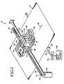
- Fig. 1 shows a portion of a color inkjet marking apparatus 10.
- the apparatus 10 includes multiple inkjet pen 14, 16, 18, 20 which print characters, symbols, graphics or other imagery and markings onto a media sheet 12.
- the pens 14-20 are shuttled along a scanning axis 26, while the media sheet 12 is moved along a media path in a media direction 28.
- the scanning axis 26 is referred to herein as a horizontal axis 26 given the same part number.
- the media direction 28 corresponds to a vertical axis 28 given the same part number.
- the axes 26, 28 may be oppositely named. Other naming conventions also may be used.
- the media sheet 12 is moved by rollers 30 on an axle 32, which in turn are driven by gears 34 and a motor 36.
- the pens 14-20 are carried in a carriage 22 which moves along a carriage rod 24.
- a drive belt 38 coupled to the carriage 22 exerts a drive force which moves the carriage 22.
- a drive motor 40 generates the drive force.
- the motor 40 turns a drive pulley 42 on a drive shaft 44.
- the drive belt 38 runs along the drive pulley 42 and an idler pulley 46 coupled to an idler spring 48.
- Carriage position and media sheet position are monitored by a processor 52.
- Carriage position is derived from a signal from a digital encoder 56 indicative of drive belt position.
- Media sheet position is determined from signals marking the passing of a media sheet at a known point and from a signal from a digital encoder.
- the motor 36 includes the digital encoder for tracking the roller 30 position.
- An optical sensor 54 detects the passing edge of the media sheet 12.
- Another optical sensor 58 moves with the carriage 22 along the carriage rod 24 for use in calibrating image registration.
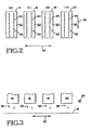
- the inkjet pens 14-20 store ink of different colors, e.g., black, cyan, magenta and yellow. As the carriage 22 and media sheet 12 translate relative to each other, the pens 14-20 scan the media sheet along the horizontal axis 26 and vertical axis 28. Referring to Fig. 2, each pen 14-20 includes a printhead 60 having an array 62 of nozzles 64. The nozzles 64 eject ink drops 66 onto the media sheet 12 as shown in Fig. 3. The number of drops, the density of the drops and the ink color of the drops determine the colors perceived by a viewer in a printed image or marking. Accordingly, to achieve accurate printing of desired colors it is important that the ink drops be placed precisely in desired positions.
- ink drops be placed precisely in desired positions.
- One challenge to such positioning is misalignment of the pens 14-20 in the carriage 22. Once the pens are locked into the carriage 22 there position is generally fixed. However, such position may vary when a pen is removed or replaced. To assure high quality printing, the registration of dots from the various printheads 60 of pens 14-20 are calibrated so that the printheads 60 are in a known position relative to each other.
- Fig. 4 shows multiple sets 70, 72, 74, 78, 80 of test patterns used for calibrating registration of the printheads 60 of the inkjet pens 14-20.
- each set includes 7 test patterns 81-87, although the number may vary.
- one printhead is taken to be a reference.
- the other printheads are calibrated relative to the position of such printhead.
- Registration of each of the non-reference printhead from corresponding pens 14, 16 and 20 is calibrated along both the horizontal axis 26 and the vertical axis 28.
- Fig. 4 shows six sets of test patterns.
- set 70 is for calibrating the black pen 14 printhead relative to the horizontal axis.
- Set 72 is for calibrating the black pen 14 printhead relative to the vertical axis.
- Set 74 is for calibrating the cyan pen 16 printhead relative to the horizontal axis.
- Set 76 is for calibrating the cyan pen 16 printhead relative to the vertical axis.
- Set 78 is for calibrating the yellow pen 20 printhead relative to the horizontal axis.
- Set 80 is for calibrating the yellow pen 20 printhead relative to the vertical axis.
- the ordering of the sets may vary.
- Each set 70-80 of test patterns is arranged along the horizontal axis 26, although in other embodiments they may be aligned along the vertical axis 28. Further, in some embodiments the horizontal calibration sets 70, 74, 78 may be aligned along one of the axes 26, 28 while the vertical calibration sets 72, 76, 80 are aligned on the other of the axes 26, 28.
- Each set 70, 74, 78 for horizontal calibration includes a plurality of vertical bars spaced apart along the horizontal axis 26.
- each set 72, 76, 80 for vertical calibration includes a plurality of horizontal bars spaced apart along the vertical axis 28. Although bars are shown and described, circles, diamonds, squares or other shapes may be used.
- Each test pattern 70-80 includes two portions. Each portion is of the same size and shape. One portion is formed of ink drops from the reference pen 18 printhead, while the other portion is formed of ink drops from the printhead being calibrated.
- sets 70, 72 include magenta ink drops from the reference pen 18 printhead and black ink drops from the pen 14 printhead.
- Sets 74, 76 include magenta ink drops from the reference pen 18 printhead and cyan ink drops from the pen 16 printhead.
- Sets 78, 80 include magenta ink drops from the reference pen 18 printhead and yellow ink drops from the pen 20 printhead.
- Fig. 5 shows 4 test patterns 83-86 of a given set of test patterns for a sample process for calibrating cyan ink pen 16 printhead for the horizontal axis 26.
- each test pattern includes a plurality of vertical bars horizontally spaced.
- the reference ink bars 90 are drawn as solid lines and the cyan bars 92 are drawn as dashed lines. From test pattern 83 to test pattern 86 the registration of the cyan bars 92 is shifting left on the page of the drawing. In test pattern 85 the cyan bars 92 and reference bars 90 overlap.
- Fig. 6 shows a magnified view of a portion of the sample test pattern 85 of Fig. 5 having the desired registration along axis 27 (e.g., one of axes 26, 28).
- Three bars 94, 96, 98 are shown.
- Each bar is shown as a plurality of ink drops.
- a reference color ink drop is depicted with an 'x', while the printhead under test ink drops (e.g., cyan) are depicted with an 'o'.
- the dots of the respective printhead also overlap for the desired registration.
- every other nozzle is used in the test pattern to draw the bars 90, 92.
- Fig. 7 shows the example where the bars 90, 92 overlap to define the respective bars 94', 96', 98' of a test pattern 85' having the desired registration along the axis 27 being calibrated.
- Fig. 6 For the desired registration the bars from the reference pen 18 printhead and the bars from the pen under test overly each other.
- the dots of the two colors also overly each other.
- the dots align along the non-calibrating axis irrespective of whether the dots themselves overlap, (e.g., for horizontal calibration, the dots align vertically even if they do not overlap).
- Fig. 8 shows a magnified view of a portion of a sample test pattern 83 having poor registration. In a poor registration the bars from the reference pen 18 printhead and the bars from the printhead under test do not overlap.
- Each bar 90, 92 is shown as a plurality of ink drops.
- test pattern 85 is shown to have desired registration and test pattern 83 is shown to have poor registration.
- the test pattern of a given set of test patterns having the best registration need not be pattern 85 and may differ from one set to the next.
- test pattern 83 need not be a poor test pattern.
- the reflectance of the media sheet is sensed for each test pattern 81-87 in a set of test patterns.
- the test pattern having the highest reflectance is the test patten having the best degree of overlapping, and thus the best registration.
- each bar of a given color ink in a test pattern has the same number of dots in width.
- the bars from a given pen are spaced apart by at least two dot widths.
- each bar of a given color ink is one dot wide and spaced five dots apart.
- the width of a bar is the same for each printhead.
- the spacing between bars of a given color is the same for each color ink. What varies is the registration of the bars of one color ink relative to the bars of the reference color ink. A best registration is selected for each set of test patterns, and thus, for each printhead under test in each of the axes 26, 28. The best registration is that corresponding to the test pattern having the highest reflectance within a set of test patterns.
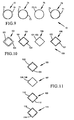
- Fig. 9 shows a plurality 70 of test patterns 72-78 according to another embodiment of this invention.
- Each test pattern includes two portions 71, 73.
- one portion 71 is printed from one inkjet printhead, while the other portion 73 is printed from another inkjet printhead.
- One inkjet printhead serves as a reference printhead.
- the other inkjet printhead is a printhead being calibrated.
- the image registration for the calibrated printhead is varied for each test pattern 72-78. Such image registration may be varied among one two printing axes.
- each test pattern may include more than two portions with each portion being printed by a different printhead. Image registration of at least one printhead is changed for each test pattern. At least one other pen serves as a reference printhead in which its image registration is the same for each test pattern.
- Each portion 71, 73 has the same size and shape.
- Each test pattern 72-78 is generally circular.
- Fig. 10 shows another plurality 100 of test patterns 102-108 in which each portion 101, 103 is diamond shaped. Although, test patterns have been described and illustrated to include one or more lines, circles or diamonds, other shapes also may be used.
- a set of test patterns are printed.
- the set includes a plurality of test patterns.
- Each test patten includes one or more bars, circles, diamonds or other shapes.
- the bars are spaced apart along an axis of calibration.
- the bars are elongated in the direction perpendicular to the axis under calibration.
- the orientation of the shape may be the same regardless of the calibration axis.
- each test pattern includes a plurality of bars of the printhead under test and the reference printhead.
- Optical sensor 58 then scans the set of test patterns to sample the reflectance of each test pattern.
- the processor 52 receives the sensor samples are derives a value indicative of reflectance for a scanned test pattern. A value is derived for each test pattern in the set.
- the processor identifies which test pattern has the highest reflectance.
- Such test pattern has the most overlapping of bars of the two colors (i.e., the ink colors of the printhead under test and of the reference printhead), and thus corresponds to the best registration for the axis calibrated.
- the registration used for such selected test pattern is the registration selected for the printhead under test for the axis calibrated.
- Another set of test patterns then is printed for calibrating relative to the other axis 26, 28. The process is repeated to calibrate registration of each printhead relative to a reference printhead.
- One of the four pens 14-10 is selected as the reference printhead as described above.
- the timing or assignment of nozzles to eject ink drops is changed.
- the registration is changed by one nozzle width from one test pattern to the next test pattern in a given set of test patterns.
- the unit of change among test patterns may vary and need not be of constant increments.
- more than two colors of ink may be used in one or more sets of test patterns of test patterns so that fewer sets of test patterns are printed to calibrate registration.
- the registration of one or more printheads is varied while the registration of at least one printhead is held constant for a given set of test patterns.
- sets 74, 76 then are used to calibrate the desired registration along the respective axes for the remaining printhead.
- sets 74, 76 include bars printed from the remaining printhead not included in sets 70, 72 and at least one other printhead.
- Sets 74, 76 may use ink from 2, 3 or 4 printheads. Only the registration of the remaining printhead is changed from pattern to pattern in sets 74, 76.
- the patterns of set 74 are scanned. The registration corresponding to the pattern with the highest reflectance is used for such remaining printhead. Such registration is the calibrated registration along the axis calibrated using set 74.
- the patterns of set 76 are scanned. The registration corresponding to the pattern with the highest reflectance is used for such remaining pen. Such registration is the calibrated registration along the axis calibrated using set 76.
- an operator inspects the test patterns, rather than an optical sensor.
- an operator enters a pattern number to identify which pattern has the best alignment.
- the reference printhead ejects black ink.
- a method for calibrating a most desirable paper advancement distance is implemented by printing a set of test patterns 105, 107, 109, 111 onto a media sheet.
- Each test pattern includes a first portion and a second portion which have a common pattern, size and shape. The portions are generally overlapping.
- a first portion 102 of test pattern 105 is printed using a first subset of nozzles of an inkjet printhead 60.
- the media sheet is advanced by a media advancement distance.
- a second portion 104 of test pattern 105 is printed with a second subset of nozzles differing from the first subset.
- the second subset is picked so as to be spaced from the first subset approximately by media advancement distance. Accordingly, the second portion 104 overlaps the first portion 102.
- test pattern 107 with generally overlapping test pattern portions 106 and 108.
- the portion 106 is printed using the first subset of nozzles while portion 108 is printed using the second subset of nozzles.
- the media advancement distance is different than the distance moved between printing the portions 102 and 104 of test pattern 105.
- the overlapping of test pattern 107 portions 106 and 108 differs from the overlapping of test pattern 105 portions 102 and 104. More particularly the amount of blank space, and thus the reflectance among the test patterns 105, 107 varies.
- the media sheet then is advanced again to a clean area of the media sheet and the steps then are repeated to achieve test pattern 109 with generally overlapping test pattern portions 110 and 112.
- the portion 110 is printed using the first subset of nozzles while portion 112 is printed using the second subset of nozzles.
- the media advancement distance is different than the distance moved between printing the portions 102 and 104 of test pattern 105, and between printing the portions 106 and 108 of test pattern 107.
- the overlapping of test pattern 109 portions 110 and 112 differs from the overlapping in test pattern 105 and in test pattern 107. More particularly the amount of blank space, and thus the reflectance among the test patterns 105, 107 and 109 varies.
- test pattern 111 with generally overlapping test pattern portions 114 and 116.
- the portion 114 is printed using the first subset of nozzles while portion 116 is printed using the second subset of nozzles.
- the media advancement distance is different than the distance moved between printing the portions of test patterns 105, 107 and 109.
- the overlapping of test pattern 111 portions 114 and 116 differs from the overlapping in test patterns 105, 107 and 109. More particularly the amount of blank space, and thus the reflectance among the test patterns 105, 107 and 109 varies. Note that the spacing between test pattern portions in a given test pattern is exaggerated for purposes of illustration.
- test pattern portion within a given test pattern is the same.
- the various test patterns 105, 107, 109 and 111 may vary in a given embodiment.
- Optical sensor 58 then scans the set of test patterns 105, 107, 109, 111 to sample the reflectance of each test pattern.
- the processor 52 receives the sensor samples are derives a value indicative of reflectance for a scanned test pattern. A value is derived for each test pattern.
- the processor identifies which test pattern has the highest reflectance. Such test pattern has the most closely aligned overlapping portions, and corresponds to a best paper advancement distance. The paper advancement distance used for such selected test pattern is the paper advancement distance selected.
- the paper advance can be calibrated according to the method described above or by an alternative method.
- the paper advance can be measured in terms of the number of nozzles moved and by which nozzles line up.
- the paper advance is altered by changing the paper advance distance in proportion to the measured nozzle distance.
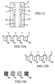
- the paper advance is calibrated together with printhead nozzle array length as described below with regard to Figs. 14A-C.
- a printhead 60 includes nozzles 64 allocated among four different portions 122, 124, 126, 128 to be calibrated. Such portions are referred to as portions a, b, c and d.
- inter-column alignment is calibrated.
- printhead array length is calibrated.
- test patterns are printed using different parts of the printhead. Deviation from nominal offsets in the nozzle positions of a given portion a, b, c or d are determined from the degree of overlap among portions of a test pattern.
- the test pattern preferably is a set of regularly spaced lines. However, other shaped may be used such as diamond patterns, circular patterns, square pattern and other regular or irregular shaped patterns.
- a first portion of each of multiple test patterns 130, 132, 134, 136 is printed using nozzles from printhead portion a as shown in Fig. 13a. Each portion is spaced from the next portion by a distance x.
- a second portion of each of the multiple test patterns is printed using nozzles from portion b. Note that the first portion and second portion of each test pattern may be printed on the same scan of the inkjet pen across the media sheet. The first portion and the second portion of each test pattern are identical. The second portions, however, are printed at a spacing y between each test portion.
- the nominal inter-column distance between the nozzles in printhead portion a and printhead portion b are to be accounted for in determining the starting position of pattern 130.
- the different patterns will be printed with offsets that are multiples of the x-y distance.
- each test pattern 130-136 will have a different reflectance as some dots are superimposed.
- the inter-column offset distance used to achieve the test pattern having the highest reflectance (i.e., most overlay) is added to the nominal inter-column distance to determine the actual inter-column distance.
- a first portion of each of multiple test patterns 140, 142, 144, 146 is printed using nozzles from printhead portion a as shown in Fig. 14a.
- the media sheet is advanced by a nominal distance equivalent to the distance between the centroids of the nozzle groups to be aligned.
- a second portion of each of the multiple test patterns is printed using nozzles from portion c.
- the first portion and the second portion of each test pattern are identical.
- the second portions are offset vertically by a small amount (e.g., one nozzle spacing).
- each test pattern 140-146 will have a different reflectance as some dots are superimposed.
- the test pattern having the highest reflectance corresponds to the array length variation between portions a and c for a given paper advance increment. In effect array length and paper advance are calibrated together.
- a calibration process is performed.
- multiple test patterns are printed. Referring to Fig. 15a a first portion of each one of multiple test patterns 150, 152, 154, 156 is printed while scanning the inkjet printhead 60 across the media sheet in a first direction 148. The spacing between each test pattern is the same. At another step a second portion of each of the test patterns is printed while scanning back across the media sheet in the opposite direction 149. The spacing between each second portion, however varies. Thus, the registration of the first portion and second portion pf each test pattern 150-156 varies.
- the test pattern of 150-156 having the highest reflectance corresponds to a calibration spacing to be used to achieve bidirectional printhead alignment.
- the method may be implemented conversely in which printheads attempt to print completely out of phase.
- the test pattern with the minimal reflectance would then corresponds to the best alignment.
- the test patterns can alternately be evaluated for the consistency of the reflectance across the pattern, where the most consistent reflectance across the pattern indicates the best alignment.
Claims (6)
- Ein Verfahren zum Kalibrieren einer Bildausrichtung für zwei Tintenstrahldruckköpfe (60), wobei jeder Druckkopf eine Mehrzahl von Tintenstrahldüsen (64) umfasst, wobei das Verfahren folgende Schritte aufweist:Drucken einer ersten Mehrzahl von Testmustern (81-87 /72-78 / 102-108) auf ein Medienblatt, wobei jedes einzelne Testmuster der Mehrzahl von Testmustern einen ersten Abschnitt (90/71/101), der mit einem ersten Tintenstrahldruckkopf gedruckt wird, und einen zweiten Abschnitt (92/73/103), der mit einem zweiten Tintenstrahldruckkopf gedruckt wird, umfasst, wobei der erste Abschnitt und der zweite Abschnitt von derselben Form sind, wobei eine Bildausrichtung von einem der zwei Tintenstrahldruckköpfe zwischen jedem einzelnen der Mehrzahl von Testmustern variiert wird; undUntersuchen der Mehrzahl von Testmustern;Auswählen der Bildausrichtung entsprechend einem der Mehrzahl von Testmustern, das den größten unbedruckten Hintergrundbereich aufweist.
- Das Verfahren gemäß Anspruch 1, bei dem, während des Schritts des Druckens der Mehrzahl von Testmustern, eine Bildausrichtung des einen Druckkopfs für jedes Testmuster variiert wird, durch Ändern einer Auswahl von Düsen des einen Druckkopfs, der beim Drucken des einen Testmusters verwendet wird.
- Das Verfahren gemäß Anspruch 1 oder 2, bei dem der Schritt des Untersuchens den Schritt des Erfassens des Reflexionsvermögens von jedem der Mehrzahl von Testmuster aufweist, und bei dem der Schritt des Auswählens das Auswählen der Bildausrichtung aufweist, die dem Testmuster mit dem höchsten Reflexionsvermögen entspricht.
- Das Verfahren gemäß Anspruch 1, 2, 3 oder 4, bei dem der erste Tintenstrahldruckkopf Tinte einer unterschiedlichen Farbe druckt als der zweite Tintenstrahldruckkopf.
- Das Verfahren gemäß Anspruch 4, bei dem jedes der ersten Mehrzahl von Testmustern eine Mehrzahl von horizontal beabstandeten vertikalen Strichen (90, 92) umfasst und durch Drucken von Tintentropfen aus zumindest zwei der Mehrzahl von Tintenstrahldruckköpfen gebildet wird, wobei die horizontale Ausrichtung von zumindest einem der zwei der Mehrzahl von Tintenstrahldruckköpfen zwischen jedem der ersten Mehrzahl von Testmustern variiert wird, wobei das Verfahren ferner folgende Schritte aufweist:Drucken einer zweiten Mehrzahl (72) von Testmustern (81 - 87), wobei jedes der zweiten Mehrzahl von Testmustern eine Mehrzahl von vertikal beabstandeten horizontalen Strichen aufweist und durch Drucken von Tintentropfen aus zumindest zwei der Mehrzahl von Tintenstrahldruckköpfen gebildet wird, wobei die vertikale Ausrichtung von zumindest einem der zwei der Mehrzahl von Tintenstrahldruckköpfen zwischen jedem der zweiten Mehrzahl von Testmustern variiert wird; undwobei das Untersuchen der Mehrzahl von Testmustern das Untersuchen der ersten und der zweiten Mehrzahl von Testmustern aufweist.
- Ein Bildausrichtungssystem für eine Mehrfarben-Tintenstrahlmarkierungsvorrichtung (10), das folgende Merkmale aufweist:eine Mehrzahl von Tintenstrahldruckköpfen (60), wobei jeder Druckkopf der Mehrzahl von Druckköpfen eine Mehrzahl von Düsen (64) aufweist, die angepasst sind, um Tinte ansprechend auf ein entsprechendes elektrisches Signal auszustoßen;einen Wagen (22), der die Mehrzahl von Tintenstrahldruckköpfen hält, wobei sich der Wagen entlang einer ersten Achse (26) bewegt;Rollen (30) zum Bewegen eines Medienblattes entlang einer zweiten Achse (28) senkrecht zu der ersten Achse;eine Steuerung (52), die elektrische Signale liefert, die verursachen, dass die Düsen Tinte auf das Medienblatt ausstoßen und eine erste Mehrzahl (70/100) von Testmustern (72-78 / 102-108) erzeugen, wobei jedes Testmuster der Mehrzahl von Testmustern einen ersten Abschnitt (71/101), der mit einem ersten Tintenstrahldruckkopf gedruckt wird, und einen zweiten Abschnitt (73/103), der mit einem zweiten Tintenstrahldruckkopf gedruckt wird, umfasst, wobei der erste Abschnitt und der zweite Abschnitt von derselben Form sind, wobei die Bildausrichtung des einen der zwei Tintenstrahldruckköpfe zwischen jedem der Mehrzahl von Testmustern variiert wird;einen Sensor (58) zum optischen Erfassen des Reflexionsvermögens von jedem der ersten Mehrzahl von Testmustern; undeinen Prozessor (52) zum Abtasten des Sensors zum Bestimmen, welches der ersten Mehrzahl von Testmustern das höchste Reflexionsvermögen aufweist, und zum Einstellen der Bildausrichtung von zumindest entweder dem ersten Tintenstrahldruckkopf oder dem zweiten Tintenstrahldruckkopf.
Applications Claiming Priority (2)
| Application Number | Priority Date | Filing Date | Title |
|---|---|---|---|
| US09/128,455 US6076915A (en) | 1998-08-03 | 1998-08-03 | Inkjet printhead calibration |
| US128455 | 1998-08-03 |
Publications (2)
| Publication Number | Publication Date |
|---|---|
| EP0978390A1 EP0978390A1 (de) | 2000-02-09 |
| EP0978390B1 true EP0978390B1 (de) | 2005-09-21 |
Family
ID=22435469
Family Applications (1)
| Application Number | Title | Priority Date | Filing Date |
|---|---|---|---|
| EP99306098A Expired - Lifetime EP0978390B1 (de) | 1998-08-03 | 1999-07-30 | Tintenstrahldruckkopfkalibrierung |
Country Status (4)
| Country | Link |
|---|---|
| US (1) | US6076915A (de) |
| EP (1) | EP0978390B1 (de) |
| JP (1) | JP2000052574A (de) |
| DE (1) | DE69927330T2 (de) |
Cited By (4)
| Publication number | Priority date | Publication date | Assignee | Title |
|---|---|---|---|---|
| US7686995B2 (en) | 1996-12-20 | 2010-03-30 | Z Corporation | Three-dimensional printer |
| US7824001B2 (en) | 2004-09-21 | 2010-11-02 | Z Corporation | Apparatus and methods for servicing 3D printers |
| US7828022B2 (en) | 2006-05-26 | 2010-11-09 | Z Corporation | Apparatus and methods for handling materials in a 3-D printer |
| WO2021021144A1 (en) * | 2019-07-31 | 2021-02-04 | Hewlett-Packard Development Company, L.P. | Optical printhead alignment |
Families Citing this family (123)
| Publication number | Priority date | Publication date | Assignee | Title |
|---|---|---|---|---|
| US6367903B1 (en) * | 1997-02-06 | 2002-04-09 | Hewlett-Packard Company | Alignment of ink dots in an inkjet printer |
| US6198549B1 (en) * | 1997-07-31 | 2001-03-06 | International Business Machines Corporation | System, method, program, and print pattern for performing registration calibration for printers by measuring density |
| JP4377974B2 (ja) * | 1998-04-03 | 2009-12-02 | キヤノン株式会社 | 光学センサのキャリブレーションを含むプリント位置合わせ方法、プリント装置およびプリントシステム |
| JP4040161B2 (ja) | 1998-04-03 | 2008-01-30 | キヤノン株式会社 | プリント位置合わせ方法およびプリント装置 |
| US6454390B1 (en) * | 1998-04-03 | 2002-09-24 | Canon Kabushiki Kaisha | Adjustment method of dot printing positions and a printing apparatus |
| JP4638968B2 (ja) * | 1998-05-29 | 2011-02-23 | キヤノン株式会社 | テストパターン形成方法および記録装置 |
| US6897978B1 (en) * | 1998-07-30 | 2005-05-24 | Canon Kabushiki Kaisha | Image processing apparatus image processing method and recording medium |
| US6196736B1 (en) * | 1998-08-18 | 2001-03-06 | Seiko Epson Corporation | Adjustment of printing position deviation during bidirectional printing |
| JP2000127360A (ja) * | 1998-10-23 | 2000-05-09 | Canon Inc | 記録装置および印字位置補正方法 |
| JP2000127370A (ja) * | 1998-10-27 | 2000-05-09 | Canon Inc | 光学センサの配置方法、当該光学センサを用いるプリント位置合わせ方法およびプリント装置 |
| JP3688913B2 (ja) * | 1998-11-19 | 2005-08-31 | シャープ株式会社 | シリアルプリンタの記録ずれ調整方法 |
| WO2000030857A1 (fr) * | 1998-11-20 | 2000-06-02 | Seiko Epson Corporation | Imprimante a points possedant une synchronisation reglable |
| US6145980A (en) * | 1998-11-24 | 2000-11-14 | Hewlett-Packard Company | Multiple-zone inkjet printer |
| US6347856B1 (en) | 1999-03-05 | 2002-02-19 | Hewlett-Packard Company | Test pattern implementation for ink-jet printhead alignment |
| JP2000301807A (ja) * | 1999-04-19 | 2000-10-31 | Canon Inc | テストパターン記録方法、情報処理装置および記録装置 |
| JP2000301810A (ja) * | 1999-04-19 | 2000-10-31 | Canon Inc | テストパターン記録方法、情報処理装置および記録装置 |
| JP4006132B2 (ja) * | 1999-05-11 | 2007-11-14 | キヤノン株式会社 | 画像データ転送方法および記録媒体 |
| JP2001353862A (ja) * | 2000-06-15 | 2001-12-25 | Brother Ind Ltd | イックジェットプリンタ |
| US6623096B1 (en) * | 2000-07-28 | 2003-09-23 | Hewlett-Packard Company | Techniques for measuring the position of marks on media and for aligning inkjet devices |
| JP4107634B2 (ja) * | 2000-08-09 | 2008-06-25 | 株式会社リコー | 画像形成装置 |
| EP1188565B1 (de) * | 2000-08-19 | 2005-11-23 | Hewlett Packard Company, a Delaware Corporation | Drucken und Kompensieren des Bildqualitätsverlustes |
| US6550906B2 (en) | 2001-01-02 | 2003-04-22 | 3M Innovative Properties Company | Method and apparatus for inkjet printing using UV radiation curable ink |
| US6554414B2 (en) | 2001-01-02 | 2003-04-29 | 3M Innovative Properties Company | Rotatable drum inkjet printing apparatus for radiation curable ink |
| US6595615B2 (en) * | 2001-01-02 | 2003-07-22 | 3M Innovative Properties Company | Method and apparatus for selection of inkjet printing parameters |
| US6412907B1 (en) * | 2001-01-24 | 2002-07-02 | Xerox Corporation | Stitching and color registration control for multi-scan printing |
| US6568780B2 (en) | 2001-04-30 | 2003-05-27 | Hewlett-Packard Company | Environmental factor detection system for inkjet printing |
| US6985254B2 (en) * | 2001-04-30 | 2006-01-10 | Hewlett-Packard Development Company, L.P. | Calibration of a multi color imaging system using a predicted color shift |
| US6382762B1 (en) | 2001-04-30 | 2002-05-07 | Hewlett-Packard Company | Peltier humidity determination system for inkjet printing |
| US6628426B2 (en) | 2001-05-22 | 2003-09-30 | Lexmark International, Inc. | Method of halftone screen linearization via continuous gradient patches |
| US7791626B2 (en) * | 2001-05-30 | 2010-09-07 | Zink Imaging, Inc. | Print head pulsing techniques for multicolor printers |
| US7388686B2 (en) * | 2003-02-25 | 2008-06-17 | Zink Imaging, Llc | Image stitching for a multi-head printer |
| US7830405B2 (en) | 2005-06-23 | 2010-11-09 | Zink Imaging, Inc. | Print head pulsing techniques for multicolor printers |
| US8377844B2 (en) * | 2001-05-30 | 2013-02-19 | Zink Imaging, Inc. | Thermally-insulating layers and direct thermal imaging members containing same |
| US6582049B2 (en) | 2001-05-31 | 2003-06-24 | Lexmark International, Inc. | Method and apparatus for detecting the position of an inkjet printhead |
| US6478401B1 (en) | 2001-07-06 | 2002-11-12 | Lexmark International, Inc. | Method for determining vertical misalignment between printer print heads |
| JP4019659B2 (ja) * | 2001-07-27 | 2007-12-12 | 富士ゼロックス株式会社 | 画像記録位置調整方法 |
| TWI290177B (en) | 2001-08-24 | 2007-11-21 | Nippon Steel Corp | A steel sheet excellent in workability and method for producing the same |
| US7413276B2 (en) * | 2001-08-28 | 2008-08-19 | Hewlett-Packard Development Company, L.P. | Diagnostic for visual detection of media advance errors |
| DE10143942A1 (de) * | 2001-09-07 | 2003-03-27 | Wifag Maschf | Prüfmittel und Verfahren zur Kontrolle des Offset- und Digitaldrucks |
| US6685297B2 (en) * | 2001-09-24 | 2004-02-03 | Xerox Corporation | Print head alignment method, test pattern used in the method, and a system thereof |
| US7006250B2 (en) * | 2001-09-27 | 2006-02-28 | Lexmark International, Inc. | Method of setting laser power and developer bias in an electrophotographic machine based on an estimated intermediate belt reflectivity |
| US6561613B2 (en) | 2001-10-05 | 2003-05-13 | Lexmark International, Inc. | Method for determining printhead misalignment of a printer |
| US6644773B2 (en) * | 2002-03-15 | 2003-11-11 | International Business Machines Corporation | Method, system, and article of manufacture for performing registration calibration for printing devices |
| US6684773B2 (en) | 2002-03-21 | 2004-02-03 | Lexmark International, Inc. | Target and algorithm for color laser printhead alignment |
| US6827419B2 (en) * | 2002-09-26 | 2004-12-07 | Hewlett-Packard Development Company, L.P. | Media allignment method and system |
| US6883892B2 (en) * | 2002-10-31 | 2005-04-26 | Hewlett-Packard Development Company, L.P. | Printing apparatus calibration |
| KR100445010B1 (ko) * | 2003-01-18 | 2004-08-21 | 삼성전자주식회사 | 인쇄 오차 보정방법 및 장치 |
| US7391525B2 (en) * | 2003-03-14 | 2008-06-24 | Lexmark International, Inc. | Methods and systems to calibrate media indexing errors in a printing device |
| US20040218199A1 (en) * | 2003-04-30 | 2004-11-04 | Regimbal Laurent A. | Printer calibration system and method |
| US7140711B2 (en) | 2003-07-21 | 2006-11-28 | 3M Innovative Properties Company | Method and apparatus for inkjet printing using radiation curable ink |
| US7073883B2 (en) * | 2003-10-16 | 2006-07-11 | Eastman Kodak Company | Method of aligning inkjet nozzle banks for an inkjet printer |
| CN1874894B (zh) * | 2003-10-31 | 2011-03-02 | 精工爱普生株式会社 | 打印方法、打印设备、打印系统 |
| JP4543673B2 (ja) * | 2003-12-16 | 2010-09-15 | セイコーエプソン株式会社 | 印刷システム |
| JP4547921B2 (ja) * | 2004-01-21 | 2010-09-22 | セイコーエプソン株式会社 | 印刷装置、印刷方法、及び印刷システム |
| US7419238B2 (en) * | 2004-02-10 | 2008-09-02 | Seiko Epson Corporation | Printing method, printing apparatus, printing system, and printed medium |
| US7708362B2 (en) * | 2004-04-21 | 2010-05-04 | Hewlett-Packard Development Company, L.P. | Printhead error compensation |
| US20050253888A1 (en) * | 2004-05-12 | 2005-11-17 | Robert Fogarty | Evaluating an image forming device |
| US7543903B2 (en) * | 2004-05-26 | 2009-06-09 | Hewlett-Packard Development Company, L.P. | Image-forming device diagnosis |
| US20050270325A1 (en) * | 2004-06-07 | 2005-12-08 | Cavill Barry R | System and method for calibrating ink ejecting nozzles in a printer/scanner |
| JP4539182B2 (ja) * | 2004-06-09 | 2010-09-08 | セイコーエプソン株式会社 | 印刷装置、コンピュータプログラム、印刷システム、及び、印刷方法 |
| JP2006069123A (ja) * | 2004-09-03 | 2006-03-16 | Fuji Photo Film Co Ltd | インク吐出方法及びインク吐出装置並びにこれを備えた画像形成装置 |
| US7387359B2 (en) | 2004-09-21 | 2008-06-17 | Z Corporation | Apparatus and methods for servicing 3D printers |
| KR100863244B1 (ko) * | 2004-10-07 | 2008-10-15 | 삼성전자주식회사 | 잉크젯 헤드 마운트 및 이를 구비하는 잉크젯 프린트 장치. |
| US7309118B2 (en) * | 2004-11-30 | 2007-12-18 | Xerox Corporation | Systems and methods for reducing cross process direction registration errors of a printhead using a linear array sensor |
| TWI250084B (en) * | 2004-12-08 | 2006-03-01 | Ind Tech Res Inst | Method of calibrating inkjet print head |
| CN100427309C (zh) * | 2004-12-16 | 2008-10-22 | 财团法人工业技术研究院 | 一种喷墨头校准的方法 |
| US20060132526A1 (en) * | 2004-12-21 | 2006-06-22 | Lexmark International Inc. | Method for forming a combined printhead alignment pattern |
| US20060158475A1 (en) * | 2005-01-19 | 2006-07-20 | Dan Arquilevich | Printer calibration |
| US20060158476A1 (en) * | 2005-01-20 | 2006-07-20 | Ng Hun Y | Method and system for aligning ink ejecting elements in an image forming device |
| US7100508B1 (en) * | 2005-02-25 | 2006-09-05 | Eastman Kodak Company | Color registration test pattern |
| JP4273126B2 (ja) * | 2005-03-04 | 2009-06-03 | キヤノン株式会社 | 記録装置および補正方法 |
| EP1701534A1 (de) * | 2005-03-10 | 2006-09-13 | Elca Informatique S.A. | Verfahren zur Kalibrierung eines Druckers |
| WO2006124829A2 (en) * | 2005-05-17 | 2006-11-23 | David John Galton | Method of, and apparatus for, measuring the quality of a printed image |
| US7390073B2 (en) * | 2005-07-29 | 2008-06-24 | Lexmark International, Inc. | Method and apparatus for performing alignment for printing with a printhead |
| EP1764996A1 (de) * | 2005-09-20 | 2007-03-21 | Agfa Graphics N.V. | Verfahren und Apparat für automatische Ausrichtung von Druckelementanordnungen |
| EP1764224A1 (de) * | 2005-09-20 | 2007-03-21 | Agfa Graphics N.V. | Verfahren und Gerät zum digitalen Drucken mit Aufrechterhaltung der Druckpunktausrichtung unter unterschiedlichen Druckverhältnissen |
| US8136910B2 (en) * | 2005-10-03 | 2012-03-20 | Hewlett-Packard Development Company, L.P. | Calibration method for a printer |
| US7724942B2 (en) * | 2005-10-31 | 2010-05-25 | Mitutoyo Corporation | Optical aberration correction for machine vision inspection systems |
| US8311311B2 (en) | 2005-10-31 | 2012-11-13 | Mitutoyo Corporation | Optical aberration correction for machine vision inspection systems |
| JP4949094B2 (ja) * | 2007-03-17 | 2012-06-06 | 株式会社リコー | 画像形成装置 |
| JP4807886B2 (ja) * | 2008-03-12 | 2011-11-02 | コニカミノルタビジネステクノロジーズ株式会社 | キャリブレーションシステム及びキャリブレーション方法 |
| JP2010042595A (ja) * | 2008-08-12 | 2010-02-25 | Seiko Epson Corp | 印刷装置、及び、印刷方法 |
| US7891757B2 (en) * | 2008-09-30 | 2011-02-22 | Eastman Kodak Company | Marking element registration |
| US7762642B2 (en) * | 2008-09-30 | 2010-07-27 | Eastman Kodak Company | Media advance calibration |
| US8174719B2 (en) * | 2008-10-29 | 2012-05-08 | Dell Products L.P. | Systems and methods for testing a printer |
| JP5434106B2 (ja) * | 2009-02-05 | 2014-03-05 | セイコーエプソン株式会社 | 流体吐出装置及びその制御方法 |
| TWI399300B (zh) * | 2009-03-06 | 2013-06-21 | Primax Electronics Ltd | 噴墨列印校正方法及噴墨列印裝置 |
| JP5473434B2 (ja) * | 2009-06-30 | 2014-04-16 | キヤノン株式会社 | 画像処理装置、画像処理システム、画像処理方法、およびプログラム |
| JP5138652B2 (ja) * | 2009-09-29 | 2013-02-06 | 大日本スクリーン製造株式会社 | 印刷装置 |
| US20110242187A1 (en) | 2010-04-06 | 2011-10-06 | Xerox Corporation | Test Pattern Effective For Fine Registration Of Inkjet Printheads And Method Of Analysis Of Image Data Corresponding To The Test Pattern In An Inkjet Printer |
| US8602518B2 (en) | 2010-04-06 | 2013-12-10 | Xerox Corporation | Test pattern effective for coarse registration of inkjet printheads and methods of analysis of image data corresponding to the test pattern in an inkjet printer |
| US8376516B2 (en) | 2010-04-06 | 2013-02-19 | Xerox Corporation | System and method for operating a web printing system to compensate for dimensional changes in the web |
| US8721026B2 (en) | 2010-05-17 | 2014-05-13 | Xerox Corporation | Method for identifying and verifying dash structures as candidates for test patterns and replacement patterns in an inkjet printer |
| JP5316519B2 (ja) * | 2010-11-12 | 2013-10-16 | セイコーエプソン株式会社 | 液体吐出装置、及び、液体吐出方法 |
| US8585173B2 (en) | 2011-02-14 | 2013-11-19 | Xerox Corporation | Test pattern less perceptible to human observation and method of analysis of image data corresponding to the test pattern in an inkjet printer |
| JP5402967B2 (ja) * | 2011-03-17 | 2014-01-29 | ブラザー工業株式会社 | 記録装置、レンチキュラーシート、及び、被記録媒体の姿勢検出方法 |
| US8964247B2 (en) * | 2011-10-28 | 2015-02-24 | Xerox Corporation | Method and systems for creating a printer model based on print columns |
| US8662625B2 (en) | 2012-02-08 | 2014-03-04 | Xerox Corporation | Method of printhead calibration between multiple printheads |
| US8939536B2 (en) | 2012-05-02 | 2015-01-27 | Xerox Corporation | Method and system for aligning printheads that eject clear ink in an inkjet printer |
| US9539835B2 (en) | 2012-11-29 | 2017-01-10 | Hewlett-Packard Development Company, L.P. | Calibration apparatus |
| US8764149B1 (en) | 2013-01-17 | 2014-07-01 | Xerox Corporation | System and method for process direction registration of inkjets in a printer operating with a high speed image receiving surface |
| CN105050818B (zh) | 2013-01-28 | 2016-10-12 | 惠普发展公司,有限责任合伙企业 | 打印校准图案的方法、校准方法和打印机 |
| US8888225B2 (en) | 2013-04-19 | 2014-11-18 | Xerox Corporation | Method for calibrating optical detector operation with marks formed on a moving image receiving surface in a printer |
| JP5505544B2 (ja) * | 2013-05-24 | 2014-05-28 | セイコーエプソン株式会社 | 液体吐出装置、液体吐出方法 |
| US9067445B2 (en) | 2013-09-17 | 2015-06-30 | Xerox Corporation | System and method of printhead calibration with reduced number of active inkjets |
| US9278566B2 (en) * | 2014-01-01 | 2016-03-08 | Scale Abilities LLC | System and process for automatic print head registration of a digital printing machine |
| EP2902205B1 (de) | 2014-01-30 | 2020-03-04 | HP Scitex Ltd | Einstellbarer Druckkopf |
| JP6442926B2 (ja) * | 2014-08-26 | 2018-12-26 | セイコーエプソン株式会社 | 液体吐出装置 |
| US9180712B1 (en) | 2014-09-12 | 2015-11-10 | Ricoh Company, Ltd. | Test patterns for print heads having two image sources |
| EP3031610A1 (de) | 2014-12-08 | 2016-06-15 | Agfa Graphics Nv | Zuverlässiges Kalibrierverfahren für industrielle Tintenstrahlsysteme |
| US9375962B1 (en) | 2015-06-23 | 2016-06-28 | Xerox Corporation | System and method for identification of marks in printed test patterns |
| CN107635781B (zh) * | 2015-07-15 | 2020-02-07 | 惠普发展公司,有限责任合伙企业 | 用于打印系统的诊断图 |
| US10440195B2 (en) | 2015-10-30 | 2019-10-08 | Hewlett-Packard Development Company, L.P. | Calibrating a media advance system of a page wide array printing device |
| JP6656371B2 (ja) * | 2015-11-19 | 2020-03-04 | ヒューレット−パッカード デベロップメント カンパニー エル.ピー.Hewlett‐Packard Development Company, L.P. | インデックス式スキャンバーを用いるダイアライメント |
| US9844961B1 (en) | 2016-10-27 | 2017-12-19 | Xerox Corporation | System and method for analysis of low-contrast ink test patterns in inkjet printers |
| US9956799B1 (en) | 2017-01-24 | 2018-05-01 | Ricoh Company, Ltd. | Test patterns for optimizing nozzle alignment of an ink-jet marking engine |
| US10279585B2 (en) | 2017-01-31 | 2019-05-07 | Xerox Corporation | Method and system for aligning ejectors that eject clear materials in a printer |
| US11135834B1 (en) | 2017-11-13 | 2021-10-05 | Hewlett-Packard Development Company, L.P. | Interferential patterns for printer calibration |
| US10594887B1 (en) | 2019-03-18 | 2020-03-17 | Xerox Corporation | Method for measuring beam to beam stitch error in the presence of variable width beams |
| US10919310B1 (en) | 2019-12-05 | 2021-02-16 | Xerox Corporation | Methods for operating printhead inkjets to attenuate ink drying in the inkjets during printing operations |
| JP7439664B2 (ja) | 2020-07-08 | 2024-02-28 | ブラザー工業株式会社 | 液体吐出装置、液体吐出システム、パターン記録方法及びプログラム |
| CN116096582A (zh) * | 2020-07-21 | 2023-05-09 | 惠普发展公司,有限责任合伙企业 | 印刷控制 |
| US11932012B2 (en) | 2022-03-11 | 2024-03-19 | Xerox Corporation | System and method for operating an inkjet printer to attenuate ink drying in the inkjets during printing operations |
Family Cites Families (20)
| Publication number | Priority date | Publication date | Assignee | Title |
|---|---|---|---|---|
| US4675696A (en) * | 1982-04-07 | 1987-06-23 | Canon Kabushiki Kaisha | Recording apparatus |
| JPH0729440B2 (ja) * | 1986-12-17 | 1995-04-05 | キヤノン株式会社 | インクジエツト記録装置 |
| US4922270A (en) * | 1989-01-31 | 1990-05-01 | Hewlett-Packard Company | Inter pen offset determination and compensation in multi-pen thermal ink jet pen printing systems |
| US5109239A (en) * | 1989-01-31 | 1992-04-28 | Hewlett-Packard Company | Inter pen offset determination and compensation in multi-pen ink jet printing systems |
| US4922268A (en) * | 1989-01-31 | 1990-05-01 | Hewlett-Packard Company | Piezoelectric detector for drop position determination in multi-pen thermal ink jet pen printing systems |
| US5036340A (en) * | 1989-01-31 | 1991-07-30 | Hewlett-Packard Company | Piezoelectric detector for drop position determination in multi-pen ink jet printing systems |
| US5353052A (en) * | 1990-05-11 | 1994-10-04 | Canon Kabushiki Kaisha | Apparatus for producing unevenness correction data |
| DE4015799A1 (de) * | 1990-05-14 | 1991-11-21 | Siemens Ag | Verfahren zum abgleichen einer seriellen aufzeichnungseinrichtung |
| US5297017A (en) * | 1991-10-31 | 1994-03-22 | Hewlett-Packard Company | Print cartridge alignment in paper axis |
| US5289208A (en) * | 1991-10-31 | 1994-02-22 | Hewlett-Packard Company | Automatic print cartridge alignment sensor system |
| DE69307237T2 (de) * | 1992-09-25 | 1997-04-24 | Hewlett Packard Co | Verfahren zum Ausrichten von Schreibstiften |
| US5404020A (en) * | 1993-04-30 | 1995-04-04 | Hewlett-Packard Company | Phase plate design for aligning multiple inkjet cartridges by scanning a reference pattern |
| US5448269A (en) * | 1993-04-30 | 1995-09-05 | Hewlett-Packard Company | Multiple inkjet cartridge alignment for bidirectional printing by scanning a reference pattern |
| US5451990A (en) * | 1993-04-30 | 1995-09-19 | Hewlett-Packard Company | Reference pattern for use in aligning multiple inkjet cartridges |
| US5313287A (en) * | 1993-04-30 | 1994-05-17 | Hewlett-Packard Company | Imposed weight matrix error diffusion halftoning of image data |
| ES2119928T3 (es) * | 1993-04-30 | 1998-10-16 | Hewlett Packard Co | Sistema de alineacion para multiples cartuchos de impresora de chorro de tinta. |
| US5397192A (en) * | 1993-11-01 | 1995-03-14 | Hewlett-Packard Company | Shuttle-type printers and methods for operating same |
| NL9400355A (nl) * | 1994-03-07 | 1995-10-02 | Stork Colorproofing | Werkwijze voor het registreren van kleurdeelbeelden en daarmee verkregen patroon van afbeeldingen. |
| US5534895A (en) * | 1994-06-30 | 1996-07-09 | Xerox Corporation | Electronic auto-correction of misaligned segmented printbars |
| US5796414A (en) * | 1996-03-25 | 1998-08-18 | Hewlett-Packard Company | Systems and method for establishing positional accuracy in two dimensions based on a sensor scan in one dimension |
-
1998
- 1998-08-03 US US09/128,455 patent/US6076915A/en not_active Expired - Lifetime
-
1999
- 1999-07-30 DE DE69927330T patent/DE69927330T2/de not_active Expired - Lifetime
- 1999-07-30 EP EP99306098A patent/EP0978390B1/de not_active Expired - Lifetime
- 1999-08-02 JP JP11219016A patent/JP2000052574A/ja active Pending
Cited By (9)
| Publication number | Priority date | Publication date | Assignee | Title |
|---|---|---|---|---|
| US7686995B2 (en) | 1996-12-20 | 2010-03-30 | Z Corporation | Three-dimensional printer |
| US8017055B2 (en) | 1996-12-20 | 2011-09-13 | Z Corporation | Three-dimensional printer |
| US7824001B2 (en) | 2004-09-21 | 2010-11-02 | Z Corporation | Apparatus and methods for servicing 3D printers |
| US8167395B2 (en) | 2004-09-21 | 2012-05-01 | 3D Systems, Inc. | Apparatus and methods for servicing 3D printers |
| US7828022B2 (en) | 2006-05-26 | 2010-11-09 | Z Corporation | Apparatus and methods for handling materials in a 3-D printer |
| US7971991B2 (en) | 2006-05-26 | 2011-07-05 | Z Corporation | Apparatus and methods for handling materials in a 3-D printer |
| US7979152B2 (en) | 2006-05-26 | 2011-07-12 | Z Corporation | Apparatus and methods for handling materials in a 3-D printer |
| US8185229B2 (en) | 2006-05-26 | 2012-05-22 | 3D Systems, Inc. | Apparatus and methods for handling materials in a 3-D printer |
| WO2021021144A1 (en) * | 2019-07-31 | 2021-02-04 | Hewlett-Packard Development Company, L.P. | Optical printhead alignment |
Also Published As
| Publication number | Publication date |
|---|---|
| US6076915A (en) | 2000-06-20 |
| DE69927330T2 (de) | 2006-08-10 |
| EP0978390A1 (de) | 2000-02-09 |
| JP2000052574A (ja) | 2000-02-22 |
| DE69927330D1 (de) | 2006-02-02 |
Similar Documents
| Publication | Publication Date | Title |
|---|---|---|
| EP0978390B1 (de) | Tintenstrahldruckkopfkalibrierung | |
| US6331038B1 (en) | Techniques for robust dot placement error measurement and correction | |
| EP0622220B1 (de) | Richtvorrichtung für Vielfach-Tintenstrahl-Kassetten beim Zweirichtungsdruck durch Abtasten eines Testmusters | |
| EP1176802B1 (de) | Techniken zum Messen der Lage von Markierungen auf Medien und zum Ausrichten von Tintenstrahlgeräten | |
| EP0622237B1 (de) | Phasenplattenentwurf für das Abgleichen durch Referenzmusterabtastung von Mehrfach-Farbstrahlkassetten | |
| EP0622239B1 (de) | Abgleichsystem für Mehrfach-Tintenstrahldruckpatronen | |
| US6457806B2 (en) | Ink-jet print pass microstepping | |
| EP1029673B1 (de) | Korrektursystem für Tröpfchenpositionierungsfehler in der Druckrichtungsachse in Tintenstrahldruckern | |
| EP0622238B1 (de) | Tintenstrahldrucker mit Referenzmuster für das Abgleichen von Mehrfach-Tintenstrahlkassetten | |
| US6109722A (en) | Ink jet printing system with pen alignment and method | |
| EP1034936B1 (de) | Tintenstrahl-Prüfmuster | |
| JP5383572B2 (ja) | プリントヘッド回転の検出方法及びシステム | |
| EP2280831B1 (de) | Einstellung einer druckanordnung und substrat in einer druckvorrichtung | |
| JP2000052574A5 (de) | ||
| CN108349273B (zh) | 校准页宽阵列打印装置的介质推进系统 | |
| WO2003071439A1 (en) | Printhead alignment test pattern and method for determining printhead misalignment | |
| US7891757B2 (en) | Marking element registration | |
| EP0622236B1 (de) | Abgleichsystem für Mehrfach-Tintenstrahldruckpatronen | |
| US8708444B2 (en) | Inkjet printer and ejection timing correction method | |
| EP1057647B1 (de) | Tintenstrahldrucker | |
| JP6040241B2 (ja) | 連続するスワスを印刷する方法 | |
| US7413276B2 (en) | Diagnostic for visual detection of media advance errors | |
| US20090102873A1 (en) | Liquid ejecting apparatus and liquid ejecting method | |
| JP2005125505A (ja) | 画像形成装置 | |
| KR20140093173A (ko) | 고속 이미지 수용 표면으로 작동하는 프린터에서 잉크젯의 처리 방향 등록 시스템 및 방법 |
Legal Events
| Date | Code | Title | Description |
|---|---|---|---|
| PUAI | Public reference made under article 153(3) epc to a published international application that has entered the european phase |
Free format text: ORIGINAL CODE: 0009012 |
|
| AK | Designated contracting states |
Kind code of ref document: A1 Designated state(s): DE GB |
|
| AX | Request for extension of the european patent |
Free format text: AL;LT;LV;MK;RO;SI |
|
| 17P | Request for examination filed |
Effective date: 20000407 |
|
| AKX | Designation fees paid |
Free format text: DE GB |
|
| RAP1 | Party data changed (applicant data changed or rights of an application transferred) |
Owner name: HEWLETT-PACKARD COMPANY, A DELAWARE CORPORATION |
|
| 17Q | First examination report despatched |
Effective date: 20030509 |
|
| GRAP | Despatch of communication of intention to grant a patent |
Free format text: ORIGINAL CODE: EPIDOSNIGR1 |
|
| GRAS | Grant fee paid |
Free format text: ORIGINAL CODE: EPIDOSNIGR3 |
|
| GRAA | (expected) grant |
Free format text: ORIGINAL CODE: 0009210 |
|
| AK | Designated contracting states |
Kind code of ref document: B1 Designated state(s): DE GB |
|
| REG | Reference to a national code |
Ref country code: GB Ref legal event code: FG4D |
|
| REF | Corresponds to: |
Ref document number: 69927330 Country of ref document: DE Date of ref document: 20051027 Kind code of ref document: P |
|
| REF | Corresponds to: |
Ref document number: 69927330 Country of ref document: DE Date of ref document: 20060202 Kind code of ref document: P |
|
| PLBE | No opposition filed within time limit |
Free format text: ORIGINAL CODE: 0009261 |
|
| STAA | Information on the status of an ep patent application or granted ep patent |
Free format text: STATUS: NO OPPOSITION FILED WITHIN TIME LIMIT |
|
| 26N | No opposition filed |
Effective date: 20060622 |
|
| REG | Reference to a national code |
Ref country code: GB Ref legal event code: 732E Free format text: REGISTERED BETWEEN 20120329 AND 20120404 |
|
| PGFP | Annual fee paid to national office [announced via postgrant information from national office to epo] |
Ref country code: GB Payment date: 20130626 Year of fee payment: 15 |
|
| PGFP | Annual fee paid to national office [announced via postgrant information from national office to epo] |
Ref country code: DE Payment date: 20130621 Year of fee payment: 15 |
|
| REG | Reference to a national code |
Ref country code: DE Ref legal event code: R119 Ref document number: 69927330 Country of ref document: DE |
|
| GBPC | Gb: european patent ceased through non-payment of renewal fee |
Effective date: 20140730 |
|
| PG25 | Lapsed in a contracting state [announced via postgrant information from national office to epo] |
Ref country code: DE Free format text: LAPSE BECAUSE OF NON-PAYMENT OF DUE FEES Effective date: 20150203 |
|
| REG | Reference to a national code |
Ref country code: DE Ref legal event code: R119 Ref document number: 69927330 Country of ref document: DE Effective date: 20150203 |
|
| PG25 | Lapsed in a contracting state [announced via postgrant information from national office to epo] |
Ref country code: GB Free format text: LAPSE BECAUSE OF NON-PAYMENT OF DUE FEES Effective date: 20140730 |