EP0978360A2 - Method and apparatus for the manufacture of parquet flooring - Google Patents
Method and apparatus for the manufacture of parquet flooring Download PDFInfo
- Publication number
- EP0978360A2 EP0978360A2 EP99111391A EP99111391A EP0978360A2 EP 0978360 A2 EP0978360 A2 EP 0978360A2 EP 99111391 A EP99111391 A EP 99111391A EP 99111391 A EP99111391 A EP 99111391A EP 0978360 A2 EP0978360 A2 EP 0978360A2
- Authority
- EP
- European Patent Office
- Prior art keywords
- bars
- pusher
- boards
- rods
- parquet
- Prior art date
- Legal status (The legal status is an assumption and is not a legal conclusion. Google has not performed a legal analysis and makes no representation as to the accuracy of the status listed.)
- Granted
Links
Images

Classifications
-
- B—PERFORMING OPERATIONS; TRANSPORTING
- B27—WORKING OR PRESERVING WOOD OR SIMILAR MATERIAL; NAILING OR STAPLING MACHINES IN GENERAL
- B27M—WORKING OF WOOD NOT PROVIDED FOR IN SUBCLASSES B27B - B27L; MANUFACTURE OF SPECIFIC WOODEN ARTICLES
- B27M3/00—Manufacture or reconditioning of specific semi-finished or finished articles
- B27M3/04—Manufacture or reconditioning of specific semi-finished or finished articles of flooring elements, e.g. parqueting blocks
- B27M3/06—Manufacture or reconditioning of specific semi-finished or finished articles of flooring elements, e.g. parqueting blocks of composite floor plates per se by assembling or jointing the parqueting blocks
Definitions
- the invention relates to a method and an apparatus for manufacturing of parquet boards, especially for prefinished parquet, at least every board consists of a base, an intermediate layer and a top layer and the intermediate layer made of numerous arranged side by side Rods is composed, which is arranged transversely to the longitudinal direction of the planks are.
- the top layer consists of about 2 m long boards that correspond to the desired parquet pattern from individual pieces of wood are glued. At During manufacture, this top layer lies with the visible side down and on the top of the top layer becomes the liner from a variety crosswise running individual rods glued. These individual bars are fed via a slide across the direction of the bar, so that the bars are parallel to each other lying down and placed on the top layer under mutual contact become.
- the finished parquet board has a tongue and groove side on the end faces, tongue and groove are each arranged in the intermediate layer. Since this intermediate layer made of unplaned raw wood, the so-called If there is a side product, simply counting the bars does not make it an exact one To achieve length of the intermediate layer in the longitudinal direction of the planks. Rather lead the tolerances in the bar width so that after cutting the Parquet boards at their ends are not always bars with a full cross-section lie as they are required for the later tongue and groove connection.
- the present invention is based on the object to simplify the manufacture of parquet boards while ensuring that at the two ends of the parquet board the rods of the intermediate layer a sufficiently large cross section for the formation of the tongue and groove connection to have.
- this object is achieved by that some of the first and last placed bars of the liner in direct contact with each other, but the bars placed between them predominantly be spaced apart.
- the invention is therefore based on the principle of inevitable tolerances to compensate for the bar width by the distances between the individual bars, so that the end rods are exactly in the desired position can be filed. However, this will be the first and last bars laid in direct contact with one another so that the forces occurring there when creating the tongue and groove connection of adjacent planks without any problems can be included.
- the number and / or size of the spacing between neighboring ones Rods are appropriately chosen so that the last inserted rod is flush comes to rest at the end of the hall.
- the bars are placed in the main area of the plank at a distance through a tray-like slideway in connection with an overlying one Pushers, such that a relative displacement between these two parts are stripped of the rods.
- the slideway can be used to gently lay the rods down on the Top layer can be pivoted.
- the spacing of the rods according to the invention is brought about by that the said pusher while laying the rods with Except for the bars placed at the beginning and at the end, slightly continuous or moves back step by step, not as a fixed stop acts, but moves in the same direction as the slideway. Becomes the pusher, for example, after dropping a rod by 1 mm each moved back, this leads to the fact that the rods each about 1 mm Have air gap to each other.
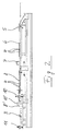
- the boards 2 are fed in via a conveyor system 1 the top layer. You can see some of these boards glued to the top are in the laying station 3.
- the bars 4 to be placed thereon are fed from the right in FIG. 1, the rods 4 loose and without connection to each other across the Boards 2 are arranged and are initially still relatively long.
- the rods 4 With help of a conveyor element 5, the rods 4 are suitable for the board length Number of pieces arranged on a lane 6 and then by a Multiple saw 7 transported. There they will be shortened to a length that the Width of the boards 2 corresponds.
- the multiple saw 7 is included Tray 8 with numerous channels 9 running in the conveying direction, whose Width is matched to the length of the sawn-off rods 4. In the embodiment only some of the rods 4 are shown in the channels 9, of course the tray is filled with sticks to the extent that it is necessary to occupy the boards 2 in the laying station 3.
- the tray 8 moves under a slide 10 through into the laying station 3, there almost sinks with the front end except for the planks of the top layer, see position 8 'in Figure 2. Then the slide 10 moves down and forward to the position 10 ', around the rods 4 from behind against a stop 11 at the front end of the Press the planks so that the bars are close together.
- the laying process begins by the tray 8, which is now used as a slideway acts, gradually moves back, so that the slide 10 Gradually strips 4, starting with the front End of the tablet 8 lying bars.
- the slide 10 After placing a few rows of bars, the slide 10 begins a rear Movement, so that all following bars are no longer close together, but are placed on gap. This continues until the last Rows of rods come to rest. These rows of bars should be close together again are stored tight, which is why the slide 10 in such a position The last row of bars stops flush with the back end of the boards 2 completes.
- the intermediate layer is thus applied in the desired arrangement and it follows in a manner known per se the application of a base which usually consists of thick strips of veneer.
- the advantage of the invention is that the previously necessary wider edge bars are omitted that the intermediate layer is reliable with the desired dimensions, especially with a full cross-section the bars 4 at the front and rear board end, is generated and that you save some wood through the air gaps in the intermediate layer.
Abstract
Description
Die Erfindung betrifft ein Verfahren und eine Vorrichtung zur Herstellung von Parkettdielen, insbesondere für Fertigparkett, wobei jede Diele zumindest aus einer Unterlage, einer Zwischenlage und einer Deckschicht besteht und die Zwischenlage aus zahlreichen nebeneinander angeordneten Stäben zusammengesetzt ist, die quer zur Dielen-Längsrichtung angeordnet sind.The invention relates to a method and an apparatus for manufacturing of parquet boards, especially for prefinished parquet, at least every board consists of a base, an intermediate layer and a top layer and the intermediate layer made of numerous arranged side by side Rods is composed, which is arranged transversely to the longitudinal direction of the planks are.
Die Decklage besteht aus etwa 2 m langen Brettern, die entsprechend dem gewünschten Parkettmuster aus einzelnen Holzstücken verleimt sind. Bei der Herstellung liegt diese Decklage mit der Sichtseite nach unten und auf die Oberseite der Decklage wird die Zwischenlage aus einer Vielzahl quer verlaufender Einzelstäbe angeleimt. Die Zufuhr dieser Einzelstäbe erfolgt über eine Rutsche quer zur Stabrichtung, so daß die Stäbe parallel nebeneinander liegend und unter gegenseitiger Anlage auf der Deckschicht abgelegt werden.The top layer consists of about 2 m long boards that correspond to the desired parquet pattern from individual pieces of wood are glued. At During manufacture, this top layer lies with the visible side down and on the top of the top layer becomes the liner from a variety crosswise running individual rods glued. These individual bars are fed via a slide across the direction of the bar, so that the bars are parallel to each other lying down and placed on the top layer under mutual contact become.
Die fertige Parkettdiele hat an den Stirnseiten eine Nut- und eine Federseite, wobei Nut und Feder jeweils in der Zwischenlage angeordnet sind. Da diese Zwischenlage aus nichtgehobeltem Rohholz, der sogenannten Seitenware, besteht, ist durch einfaches Abzählen der Stäbe keine exakte Länge der Zwischenlage in Dielen-Längsrichtung zu erzielen. Vielmehr führen die Toleranzen in der Stabbreite dazu, daß nach dem Ablängen der Parkettdielen an deren Enden nicht immer Stäbe mit vollem Querschnitt liegen, wie sie für die spätere Nut-Feder-Verbindung benötigt werden. The finished parquet board has a tongue and groove side on the end faces, tongue and groove are each arranged in the intermediate layer. Since this intermediate layer made of unplaned raw wood, the so-called If there is a side product, simply counting the bars does not make it an exact one To achieve length of the intermediate layer in the longitudinal direction of the planks. Rather lead the tolerances in the bar width so that after cutting the Parquet boards at their ends are not always bars with a full cross-section lie as they are required for the later tongue and groove connection.
Bei den bekannten Systemen löst man dieses Problem dadurch, daß an den beiden Enden der Zwischenlage sogenannte Endbrettchen eingelegt werden, die etwa zwei- bis viermal so breit sind, wie die Rohholzstäbe. Durch diese überbreiten Randstäbe ist sichergestellt, daß genügend breite Holzquerschnitte für die Nut-Feder-Verbindungen zur Verfügung stehen, und zwar auch dann noch, wenn die Parkettdielen auf das vorgeschriebene Längenmaß gesägt worden sind.In the known systems this problem is solved in that so-called end boards inserted into the two ends of the intermediate layer that are about two to four times as wide as the raw wood rods. These extra-wide edge bars ensure that they are wide enough Wood cross sections are available for the tongue and groove connections, even if the parquet boards meet the prescribed requirements Have been sawn.
Die Verwendung unterschiedlich breiter Stäbe für die Zwischenlage ist aber aufwendig, weil die Randstäbe jeweils von Hand eingelegt werden müssen.The use of rods of different widths for the intermediate layer is but expensive because the edge bars are inserted by hand have to.
Hiervon ausgehend liegt der vorliegenden Erfindung die Aufgabe zugrunde, die Herstellung von Parkettdielen zu vereinfachen und gleichzeitig sicherzustellen, daß an den beiden Enden der Parkettdiele die Stäbe der Zwischenlage einen genügend großen Querschnitt für die Bildung der Nut-Feder-Verbindung haben.Proceeding from this, the present invention is based on the object to simplify the manufacture of parquet boards while ensuring that at the two ends of the parquet board the rods of the intermediate layer a sufficiently large cross section for the formation of the tongue and groove connection to have.
Diese Aufgabe wird hinsichtlich des Herstellungsverfahrens dadurch gelöst, daß einige der zuerst und zuletzt aufgelegten Stäbe der Zwischenlage in direkter Anlage aneinander, die dazwischen aufgelegten Stäbe jedoch überwiegend voneinander beabstandet angeordnet werden.With regard to the manufacturing process, this object is achieved by that some of the first and last placed bars of the liner in direct contact with each other, but the bars placed between them predominantly be spaced apart.
Die Erfindung beruht also auf dem Prinzip, die unvermeidlichen Toleranzen in der Stabbreite durch Abstände zwischen den einzelnen Stäben aufzufangen, so daß die endseitigen Stäbe exakt in der gewünschten Position abgelegt werden können. Dabei werden jedoch die ersten und letzten Stäbe in direkter Anlage aneinander verlegt, damit die dort auftretenden Kräfte beim Herstellen der Nut-Feder-Verbindung benachbarter Dielen problemlos aufgenommen werden können.The invention is therefore based on the principle of inevitable tolerances to compensate for the bar width by the distances between the individual bars, so that the end rods are exactly in the desired position can be filed. However, this will be the first and last bars laid in direct contact with one another so that the forces occurring there when creating the tongue and groove connection of adjacent planks without any problems can be included.
Die Anzahl und/oder Größe der Beabstandungen zwischen benachbarten Stäben wird zweckmäßig so gewählt, daß der zuletzt eingelegte Stab bündig an das Ende der Diele zu liegen kommt. The number and / or size of the spacing between neighboring ones Rods are appropriately chosen so that the last inserted rod is flush comes to rest at the end of the hall.
Das distanzierte Ablegen der Stäbe im Hauptbereich der Diele erfolgt durch eine tablettartige Gleitbahn in Verbindung mit einem darüber befindlichen Abschieber, derart, daß durch eine Relativverschiebung zwischen diesen beiden genannten Teilen die Stäbe abgestreift werden. Die Gleitbahn kann dabei zum sanften Ablegen der Stäbe nach unten auf die Decklage geschwenkt werden.The bars are placed in the main area of the plank at a distance through a tray-like slideway in connection with an overlying one Pushers, such that a relative displacement between these two parts are stripped of the rods. The slideway can be used to gently lay the rods down on the Top layer can be pivoted.
Die erfindungsgemäße Distanzierung der Stäbe wird dadurch herbeigeführt, daß der genannte Abschieber während des Ablegens der Stäbe mit Ausnahme der am Anfang und am Ende gelegten Stäbe geringfügig kontinuierlich oder schrittweise zurückfährt, also nicht als ortsfester Anschlag fungiert, sondern in der gleichen Richtung verfährt, wie die Gleitbahn. Wird der Abschieber beispielsweise nach Abwurf eines Stabes jeweils um 1 mm zurückbewegt, so führt dies dazu, daß die Stäbe jeweils etwa 1 mm Luftspalt zueinander haben.The spacing of the rods according to the invention is brought about by that the said pusher while laying the rods with Except for the bars placed at the beginning and at the end, slightly continuous or moves back step by step, not as a fixed stop acts, but moves in the same direction as the slideway. Becomes the pusher, for example, after dropping a rod by 1 mm each moved back, this leads to the fact that the rods each about 1 mm Have air gap to each other.
Damit die Stäbe im Randbereich dicht aneinanderliegen, werden sie vor dem Ablegen zunächst gegen einen ortsfesten Anschlag am vorderen Ende der Diele gedrückt. In diesem Zustand, wo die Stäbe dicht aneinanderliegen, werden dann einige Stäbe dicht an dicht abgelegt, indem die Gleitbahn zurückfährt, während der Abschieber ortsfest bleibt. Erst danach fährt der Abschieber langsam zurück, so daß die folgenden Stäbe mit Lücke abgelegt werden. Vor Ablage der letzten Stäbe wird die Bewegung des Abschiebers wieder gestoppt, so daß diese Stäbe wieder dicht an dicht abgelegt werden. Diese Position des Abschiebers definiert dann gleichzeitig die Position des letzten Stabes.So that the bars are close together in the edge area, they are in front placing it first against a fixed stop at the front end the hallway pressed. In this state, where the bars are close together, some bars are then placed close to each other by the slideway returns while the pusher remains stationary. Only then drives the pusher slowly returns so that the following rods are deposited with a gap become. Before the last rods are deposited, the movement of the pusher stopped again so that these rods are placed close together again become. This position of the pusher then defines at the same time the position of the last bar.
Weitere Merkmale und Vorteile der Erfindung ergeben sich aus den übrigen Ansprüchen und der nachfolgenden Beschreibung eines Ausführungsbeispieles anhand der Zeichnung; dabei zeigt
Figur 1- eine schematische Draufsicht auf die erfindungsgemäße Vorrichtung von oben und
Figur 2- eine entsprechende Seitenansicht der Vorrichtung.
- Figure 1
- a schematic plan view of the device according to the invention from above and
- Figure 2
- a corresponding side view of the device.
In Figur 1 erfolgt über ein Fördersystem 1 die Zuführung der Bretter 2 für
die Decklage. Man sieht einige dieser Bretter, die an ihrer Oberseite beleimt
sind, in der Legestation 3.In FIG. 1, the
Die Zufuhr der darauf aufzulegenden Stäbe 4 erfolgt in Figur 1 von rechts,
wobei die Stäbe 4 lose und ohne Verbindung miteinander quer zu den
Brettern 2 angeordnet sind und zunächst noch relativ lang sind. Mit Hilfe
eines Förderelementes 5 werden die Stäbe 4 in der zur Dielenlänge passenden
Stückzahl auf einer Bahn 6 arrangiert und sodann durch eine
Mehrfachsäge 7 befördert. Sie werden dort auf eine Länge gekürzt, die der
Breite der Bretter 2 entspricht. An die Mehrfachsäge 7 schließt sich ein
Tablett 8 mit zahlreichen in Förderrichtung laufenden Kanälen 9 an, deren
Breite auf die Länge der abgesägten Stäbe 4 abgestimmt ist. Im Ausführungsbeispiel
sind nur einige der Stäbe 4 in den Kanälen 9 dargestellt,
selbstverständlich ist das Tablett aber in dem Maße mit Stäben gefüllt, wie
es zur Belegung der Bretter 2 in der Legestation 3 notwendig ist. Sobald
dieser Zustand erreicht ist, fährt das Tablett 8 unter einem Schieber 10
hindurch in die Legestation 3, senkt sich dort mit dem vorderen Ende nahezu
bis auf die Bretter der Decklage ab, vergl. Position 8' in Figur 2. Sodann
fährt der Schieber 10 nach unten und nach vorn in die Position 10',
um die Stäbe 4 von hinten gegen einen Anschlag 11 am vorderen Ende der
Dielen zu pressen, so daß die Stäbe dicht aneinander liegen.The
Dann beginnt der Ablegevorgang, indem das Tablett 8, das nun als Gleitbahn
fungiert, allmählich wieder zurückfährt, so daß der Schieber 10 die
Stäbe 4 nach und nach abstreift, und zwar beginnend mit den am vorderen
Ende des Tablettes 8 liegenden Stäben.Then the laying process begins by the
Nach Ablage einiger Stabreihen beginnt der Schieber 10 eine rückwärtige
Fahrbewegung, so daß alle folgenden Stäbe nicht mehr dicht an dicht,
sondern auf Lücke abgelegt werden. Dies setzt sich fort, bis die letzten
Stabreihen zur Ablage kommen. Diese Stabreihen sollen wieder dicht an
dicht abgelegt werden, weshalb der Schieber 10 in einer solchen Position
stoppt, daß die letzte Stabreihe bündig mit dem hinteren Ende der Bretter
2 abschließt.After placing a few rows of bars, the
In Figur 1 ist in der Legestation 3 nur über einem der Bretter 2 die erfindungsgemäße
Ablage der Stäbe 4 dargestellt, während die übrigen Bretter
2 noch überwiegend frei sind. Tatsächlich werden aber alle Bretter 2
gleichzeitig von vorn bis hinten mit den Stäben 4 in der erfindungsgemäßen
Anordnung belegt.In Figure 1, the
Damit ist die Zwischenlage in der gewünschten Anordnung aufgebracht und es folgt in an sich bekannter Weise das Anbringen einer Unterlage, die in der Regel aus dicken Furnierstreifen besteht.The intermediate layer is thus applied in the desired arrangement and it follows in a manner known per se the application of a base which usually consists of thick strips of veneer.
Vorstehend ist die erfindungsgemäße Distanzierung der Stäbe durch Verfahrung
des Abschiebers 10 dargestellt worden. Es liegt aber auch im
Rahmen der Erfindung, den Abschieber 10 in seiner Abschiebeposition
stehen zu lassen und statt dessen die Bretter 2 in der Legestation zu verfahren.
Nach Ablage der ersten Stabreihen würden also die Bretter 2 langsam
in Pfeilrichtung nach vorn bewegt werden, so daß die folgenden Stäbe
4 die erwünschte Distanzierung erhalten. Die Ablage der letzten Stabreihen
würde dann wieder bei stillstehenden Brettern erfolgen. Im Prinzip wird
also die während der Stabablage erfolgende Verschiebung des Abschiebers
10 ersetzt durch eine entgegengesetzt gerichtete Verschiebung der
Bretter 2 in der Setzstation 3.Above is the spacing of the bars according to the invention by moving
of the
Zusammenfassend besteht der Vorteil der Erfindung darin, daß die bisher
notwendigen breiteren Randstäbe entfallen, daß die Zwischenlage zuverlässig
mit den gewünschten Abmessungen, insbesondere mit vollem Querschnitt
der Stäbe 4 an vorderem und hinterem Brettende, erzeugt wird und
daß man durch die Luftspalte in der Zwischenlage noch etwas Holz spart.In summary, the advantage of the invention is that the previously
necessary wider edge bars are omitted that the intermediate layer is reliable
with the desired dimensions, especially with a full cross-section
the
Claims (7)
dadurch gekennzeichnet,
characterized,
dadurch gekennzeichnet,
characterized,
dadurch gekennzeichnet,
characterized,
dadurch gekennzeichnet,
characterized,
dadurch gekennzeichnet,
characterized,
dadurch gekennzeichnet,
characterized,
dadurch gekennzeichnet,
characterized,
Applications Claiming Priority (2)
| Application Number | Priority Date | Filing Date | Title |
|---|---|---|---|
| DE19834895A DE19834895A1 (en) | 1998-08-03 | 1998-08-03 | Method and device for producing parquet boards |
| DE19834895 | 1998-08-03 |
Publications (3)
| Publication Number | Publication Date |
|---|---|
| EP0978360A2 true EP0978360A2 (en) | 2000-02-09 |
| EP0978360A3 EP0978360A3 (en) | 2004-04-07 |
| EP0978360B1 EP0978360B1 (en) | 2005-09-14 |
Family
ID=7876227
Family Applications (1)
| Application Number | Title | Priority Date | Filing Date |
|---|---|---|---|
| EP99111391A Expired - Lifetime EP0978360B1 (en) | 1998-08-03 | 1999-06-11 | Method and apparatus for the manufacture of parquet flooring |
Country Status (3)
| Country | Link |
|---|---|
| EP (1) | EP0978360B1 (en) |
| AT (1) | ATE304434T1 (en) |
| DE (2) | DE19834895A1 (en) |
Cited By (2)
| Publication number | Priority date | Publication date | Assignee | Title |
|---|---|---|---|---|
| WO2000067968A2 (en) * | 1999-05-10 | 2000-11-16 | A. Costa S.P.A. | Method of gluing strips of wood to produce composite strip blocks and the machine suited to performing this method |
| EP1970178A1 (en) | 2007-03-15 | 2008-09-17 | Josef Czillich | Method for precise alignment of rough sawn trimmed timber lamellae |
Families Citing this family (4)
| Publication number | Priority date | Publication date | Assignee | Title |
|---|---|---|---|---|
| DE10061516A1 (en) * | 2000-12-08 | 2002-06-20 | Buerkle Gmbh Robert | Method and device for producing a central layer of a parquet board |
| DE102007062144B4 (en) * | 2007-07-26 | 2015-11-19 | Hamberger Industriewerke Gmbh | Floor panel and method of making a floor panel |
| DE102009012695B4 (en) * | 2009-02-23 | 2014-04-17 | Hamberger Industriewerke Gmbh | Method for producing a floor, wall or ceiling element, device for carrying out the method and plate blank for such an element |
| DE102014101578B3 (en) * | 2014-02-07 | 2015-07-09 | Tilo Gmbh | Process for producing a rod center layer for the production of floor elements |
Citations (3)
| Publication number | Priority date | Publication date | Assignee | Title |
|---|---|---|---|---|
| US3671353A (en) * | 1968-04-01 | 1972-06-20 | Boen Bruk | Process for the continuous production of laminated wood of the parquet type |
| US3966529A (en) * | 1972-09-07 | 1976-06-29 | Shigeharu Kuroda | Method of making a pallet |
| DE3921368A1 (en) * | 1989-06-29 | 1990-10-18 | Erwin Dimter | Set up for gluing joints of wooden battens - includes two-level pressing process with two base plates and two returns stops |
Family Cites Families (1)
| Publication number | Priority date | Publication date | Assignee | Title |
|---|---|---|---|---|
| BE1001594A6 (en) * | 1988-04-27 | 1989-12-12 | Lassaux Leon Paul | Parquet panel=prefabrication method - glues thin planks to rear of strips with gap between them |
-
1998
- 1998-08-03 DE DE19834895A patent/DE19834895A1/en not_active Withdrawn
-
1999
- 1999-06-11 EP EP99111391A patent/EP0978360B1/en not_active Expired - Lifetime
- 1999-06-11 DE DE59912544T patent/DE59912544D1/en not_active Expired - Lifetime
- 1999-06-11 AT AT99111391T patent/ATE304434T1/en active
Patent Citations (3)
| Publication number | Priority date | Publication date | Assignee | Title |
|---|---|---|---|---|
| US3671353A (en) * | 1968-04-01 | 1972-06-20 | Boen Bruk | Process for the continuous production of laminated wood of the parquet type |
| US3966529A (en) * | 1972-09-07 | 1976-06-29 | Shigeharu Kuroda | Method of making a pallet |
| DE3921368A1 (en) * | 1989-06-29 | 1990-10-18 | Erwin Dimter | Set up for gluing joints of wooden battens - includes two-level pressing process with two base plates and two returns stops |
Cited By (3)
| Publication number | Priority date | Publication date | Assignee | Title |
|---|---|---|---|---|
| WO2000067968A2 (en) * | 1999-05-10 | 2000-11-16 | A. Costa S.P.A. | Method of gluing strips of wood to produce composite strip blocks and the machine suited to performing this method |
| WO2000067968A3 (en) * | 1999-05-10 | 2001-02-08 | Costa S P A A | Method of gluing strips of wood to produce composite strip blocks and the machine suited to performing this method |
| EP1970178A1 (en) | 2007-03-15 | 2008-09-17 | Josef Czillich | Method for precise alignment of rough sawn trimmed timber lamellae |
Also Published As
| Publication number | Publication date |
|---|---|
| ATE304434T1 (en) | 2005-09-15 |
| EP0978360B1 (en) | 2005-09-14 |
| EP0978360A3 (en) | 2004-04-07 |
| DE59912544D1 (en) | 2005-10-20 |
| DE19834895A1 (en) | 2000-02-10 |
Similar Documents
| Publication | Publication Date | Title |
|---|---|---|
| DE2432333A1 (en) | BELT CONVEYOR | |
| DE69506032T3 (en) | Apparatus for producing sheets of mineral wool | |
| EP0978360B1 (en) | Method and apparatus for the manufacture of parquet flooring | |
| EP0666156B1 (en) | Process and device for separating from each other, rows of parallelepiped blocks from porous concrete still in a non-cured state | |
| DE2348569B2 (en) | Method for regrouping stacks of building blocks and device for carrying out the method | |
| EP1749627B1 (en) | Apparatus and method for manufacturing veneer panels | |
| DE3306852C1 (en) | Device for indenting extruded clay pieces transversely to their longitudinal direction | |
| DE2852456C2 (en) | Device for on and off panels in the manufacture of laminated panels | |
| DE3020120C2 (en) | Device for adjusting burner cassettes on pallets | |
| WO1995035192A1 (en) | Process and device for producing a top layer for ready-use parquet flooring | |
| DE2357530C2 (en) | Method and device for the production of moldings, in particular split tiles | |
| EP0496341A2 (en) | Method and apparatus for the manufacture of parquet flooring | |
| DE102010026578B4 (en) | Method for producing a cross-laminated board and apparatus for carrying out the method | |
| DE2545686A1 (en) | Shaker conveyor distributor for screws - has sliding bars which feed several work stations from one supply line | |
| EP0499899A1 (en) | Device for separating piece goods built up to parcels | |
| DE2046054B2 (en) | Device for feeding plate blanks | |
| EP0067147A1 (en) | Method of mixing blocks, especially parqueting blocks | |
| DE937792C (en) | Device for the production of wooden panels from rods, slats, slats, veneers or the like. | |
| AT236271B (en) | Plant for the production of brick blanks | |
| DE1207593B (en) | Device for loading multi-stage presses through loading trays | |
| DE3913160A1 (en) | Method of producing wood panels - by using basic board tongued or grooved and cut into lengths at angle to its long sides | |
| DE1126121B (en) | Machine for assembling mosaic parquet panels | |
| DE2312946C3 (en) | Method and device for forming a setting layer from bricks | |
| DE2351840C3 (en) | Method and device for stacking flat bars in the rake cooling bed | |
| DE2228373B1 (en) | PROCESS FOR GLUING BOARDS TO A CONTINUOUS PANEL TAPE AND CONTINUOUS JOINT BONDING PRESS FOR THIS |
Legal Events
| Date | Code | Title | Description |
|---|---|---|---|
| PUAI | Public reference made under article 153(3) epc to a published international application that has entered the european phase |
Free format text: ORIGINAL CODE: 0009012 |
|
| AK | Designated contracting states |
Kind code of ref document: A2 Designated state(s): AT BE CH CY DE DK ES FI FR GB GR IE IT LI LU MC NL PT SE |
|
| AX | Request for extension of the european patent |
Free format text: AL;LT;LV;MK;RO;SI |
|
| PUAL | Search report despatched |
Free format text: ORIGINAL CODE: 0009013 |
|
| AK | Designated contracting states |
Kind code of ref document: A3 Designated state(s): AT BE CH CY DE DK ES FI FR GB GR IE IT LI LU MC NL PT SE |
|
| AX | Request for extension of the european patent |
Extension state: AL LT LV MK RO SI |
|
| 17P | Request for examination filed |
Effective date: 20040514 |
|
| GRAP | Despatch of communication of intention to grant a patent |
Free format text: ORIGINAL CODE: EPIDOSNIGR1 |
|
| AKX | Designation fees paid |
Designated state(s): AT DE FI FR IT SE |
|
| GRAS | Grant fee paid |
Free format text: ORIGINAL CODE: EPIDOSNIGR3 |
|
| GRAA | (expected) grant |
Free format text: ORIGINAL CODE: 0009210 |
|
| AK | Designated contracting states |
Kind code of ref document: B1 Designated state(s): AT DE FI FR IT SE |
|
| REF | Corresponds to: |
Ref document number: 59912544 Country of ref document: DE Date of ref document: 20051020 Kind code of ref document: P |
|
| REG | Reference to a national code |
Ref country code: SE Ref legal event code: TRGR |
|
| ET | Fr: translation filed | ||
| PLBE | No opposition filed within time limit |
Free format text: ORIGINAL CODE: 0009261 |
|
| STAA | Information on the status of an ep patent application or granted ep patent |
Free format text: STATUS: NO OPPOSITION FILED WITHIN TIME LIMIT |
|
| 26N | No opposition filed |
Effective date: 20060615 |
|
| PGFP | Annual fee paid to national office [announced via postgrant information from national office to epo] |
Ref country code: FI Payment date: 20120620 Year of fee payment: 14 Ref country code: FR Payment date: 20120705 Year of fee payment: 14 Ref country code: SE Payment date: 20120625 Year of fee payment: 14 |
|
| PG25 | Lapsed in a contracting state [announced via postgrant information from national office to epo] |
Ref country code: SE Free format text: LAPSE BECAUSE OF NON-PAYMENT OF DUE FEES Effective date: 20130612 |
|
| REG | Reference to a national code |
Ref country code: SE Ref legal event code: EUG |
|
| PG25 | Lapsed in a contracting state [announced via postgrant information from national office to epo] |
Ref country code: FI Free format text: LAPSE BECAUSE OF NON-PAYMENT OF DUE FEES Effective date: 20130611 |
|
| REG | Reference to a national code |
Ref country code: FR Ref legal event code: ST Effective date: 20140228 |
|
| PG25 | Lapsed in a contracting state [announced via postgrant information from national office to epo] |
Ref country code: FR Free format text: LAPSE BECAUSE OF NON-PAYMENT OF DUE FEES Effective date: 20130701 |
|
| PGFP | Annual fee paid to national office [announced via postgrant information from national office to epo] |
Ref country code: DE Payment date: 20180606 Year of fee payment: 20 |
|
| PGFP | Annual fee paid to national office [announced via postgrant information from national office to epo] |
Ref country code: AT Payment date: 20180620 Year of fee payment: 20 |
|
| PGFP | Annual fee paid to national office [announced via postgrant information from national office to epo] |
Ref country code: IT Payment date: 20180622 Year of fee payment: 20 |
|
| REG | Reference to a national code |
Ref country code: DE Ref legal event code: R071 Ref document number: 59912544 Country of ref document: DE |
|
| REG | Reference to a national code |
Ref country code: AT Ref legal event code: MK07 Ref document number: 304434 Country of ref document: AT Kind code of ref document: T Effective date: 20190611 |