EP0976518A2 - Method and apparatus for making a polygonal foam block of bonded foam pieces - Google Patents
Method and apparatus for making a polygonal foam block of bonded foam pieces Download PDFInfo
- Publication number
- EP0976518A2 EP0976518A2 EP99114113A EP99114113A EP0976518A2 EP 0976518 A2 EP0976518 A2 EP 0976518A2 EP 99114113 A EP99114113 A EP 99114113A EP 99114113 A EP99114113 A EP 99114113A EP 0976518 A2 EP0976518 A2 EP 0976518A2
- Authority
- EP
- European Patent Office
- Prior art keywords
- section
- cross
- filling
- block
- walls
- Prior art date
- Legal status (The legal status is an assumption and is not a legal conclusion. Google has not performed a legal analysis and makes no representation as to the accuracy of the status listed.)
- Granted
Links
Images
Classifications
-
- B—PERFORMING OPERATIONS; TRANSPORTING
- B29—WORKING OF PLASTICS; WORKING OF SUBSTANCES IN A PLASTIC STATE IN GENERAL
- B29C—SHAPING OR JOINING OF PLASTICS; SHAPING OF MATERIAL IN A PLASTIC STATE, NOT OTHERWISE PROVIDED FOR; AFTER-TREATMENT OF THE SHAPED PRODUCTS, e.g. REPAIRING
- B29C67/00—Shaping techniques not covered by groups B29C39/00 - B29C65/00, B29C70/00 or B29C73/00
-
- B—PERFORMING OPERATIONS; TRANSPORTING
- B29—WORKING OF PLASTICS; WORKING OF SUBSTANCES IN A PLASTIC STATE IN GENERAL
- B29C—SHAPING OR JOINING OF PLASTICS; SHAPING OF MATERIAL IN A PLASTIC STATE, NOT OTHERWISE PROVIDED FOR; AFTER-TREATMENT OF THE SHAPED PRODUCTS, e.g. REPAIRING
- B29C44/00—Shaping by internal pressure generated in the material, e.g. swelling or foaming ; Producing porous or cellular expanded plastics articles
- B29C44/34—Auxiliary operations
- B29C44/58—Moulds
- B29C44/585—Moulds with adjustable size of the mould cavity
Definitions
- the invention relates to a method and an apparatus for producing Foam blocks with a square cross-section in the flake composite, whereby foam flakes filled into a molding box with adjacent molding walls and the filling is then stamped to the desired one Density or block height is compressed and the finished block is then removed from the mold.
- the density cross-section is homogeneous is achievable, it is disadvantageous in the case of angular filling cross sections that the Block production, especially depending on the flake size and the Tendency of the flakes to form bridges when filling the flakes into the Form box especially in the corners of which form cavities and roundings in addition, a lower density is created in these corners than in the interior of the block.
- the processing of flakes in the usual sizes from 12 to 15 mm causes the difficulties mentioned.
- This object is achieved in that before filling the foam flakes the cross section in each corner formed by two mold walls on a filling cross section is expanded, and that after filling the foam flakes Filling cross section to the desired shape of the cross section of the finished Blockes is reduced, and only then the filling to the desired density or block height is compressed.
- the new device for producing foam blocks with an angular cross-section in the flake composite process starts from a molding box with one Floor and several adjoining molded walls and a stamp that can be moved in the direction of the floor.
- each one is separated by two Form walls formed corner one of the form walls is divided into a fixed wall part and a flap held thereon and movable about a vertical pivot axis, which is between an outward-facing position and one with the fixed Wall part parallel position is pivotable.
- the mold wall abutting against a flap preferably has in the area of the swivel angle ⁇ of the flap corresponds to this swivel angle ⁇ Curvature on.
- This embodiment is particularly advantageous because then when filling the Flakes in the molding box always have a seal when the flaps are pivoted outwards to the adjacent mold wall, so that no flakes emerge can. This seal remains even when the flaps are returned to their end position receive.
- the flaps can preferably be actuated with a hydraulic device.
- the new device with a Control unit equipped so that the manufacturing operations are essentially automatic or run semi-automatically.
- This control unit acts accordingly on the Stamp and the hydraulic devices of the flaps and on the emptying process on.
- the device is emptied in a manner known per se by pulling up of the correspondingly designed molded box and pushing away the finished one Block or by folding mold walls down and removing the block. In any case, the stamp must be retracted before emptying.
- the molding box is preferably in a manner known per se has a rectangular or square cross section.
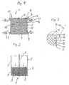
- the device consists of a molding box 1 for the production of a Composite block 2 (Fig. 2) with a square cross section.
- the molding box 1 is limited by a bottom 3 and mold walls 4, 5.
- Above the molding box 1 is a movable into it, hydraulically actuated and not shown by one Control device controllable stamp 6 arranged.
- Its pressing surface 7 corresponds in size and shape essentially the cross section 8 of the block to be manufactured 2.
- Die Ends of the opposing mold walls 4 have a curvature 9 (Fig. 2, 3), while the perpendicular to it, opposite each other Molded walls 5 each consist of a wall part 10, on which flaps 11 held movable about a pivot axis 12 by means of hydraulic devices 13 are. Corners 14 are formed between the walls 4 and the flaps 11.
- the filling cross section is designated 15 and the filling 16.
- Fig. 2 the stamp 6 is in the end position of the compression process and the block 2 is enclosed by this, the bottom 3 and the mold walls 4, 5, wherein the wall part 10 and the flaps 11 are parallel to each other.
- the mold walls 4, 5 of the mold box 1 rest on the floor 3 when the flaps 11 of the mold walls 5 are pivoted outward by the angle ⁇ of 30 °.
- the flaps 11 lie sealingly on the curvatures 9.
- polyurethane foam flakes sprayed with binder and having an edge length of approximately 10 to 15 mm are now introduced into the filling cross section 15 in a predetermined amount.
- the loose bed of such foam flakes has a density of about 15 kg / m 3 .
- the filling 16 located in the molding box 1 is to be compressed to a block height of 0.5 m at a density of 60 kg / m 3 .
- the flaps 11 are pivoted inwards into the parallel position with the wall parts 10.
- the flakes located in the enlarged corners 14 are displaced inwards and thereby fill any cavities that have formed. Since the increase in cross section or volume for the filling process was previously known from empirical determinations, when the flaps 11 and the wall parts 10 reached the parallel position, a homogeneous density was obtained over the entire cross section 8. Now the punch 6 is raised and then the molding box 1 pulled up. The finished block 2 can now be removed.
Abstract
Description
Die Erfindung betrifft ein Verfahren und eine Vorrichtung zum Herstellen von Schaumstoffblöcken mit eckigem Querschnitt im Flocken-Verbund, wobei Schaumstoffflocken in einen Formkasten mit aneinandergrenzenden Formwänden eingefüllt werden und die Füllung anschließend mittels eines Stempels auf die gewünschte Dichte bzw. Blockhöhe verdichtet und der fertige Block danach entformt wird.The invention relates to a method and an apparatus for producing Foam blocks with a square cross-section in the flake composite, whereby foam flakes filled into a molding box with adjacent molding walls and the filling is then stamped to the desired one Density or block height is compressed and the finished block is then removed from the mold.
Die Herstellung von Verbundblöcken mit eckigem Querschnitt aus Schaumstoffflocken, beispielsweise Polyurethan-Schaumstoffflocken, nach dem vorbeschriebenen Verfahren ist allgemein bekannt. Dabei werden die Flocken mit einem Bindemittel besprüht oder miteinander versintert oder verschmolzen. Je nach der Art des Füllquerschnitts des gewählten Formkastens weisen die gefertigten Blöcke neben der Rundblockform in der Regel rechteckigen oder quadratischen Querschnitt auf; sie können aber auch eine andere eckige Form aufweisen.The production of composite blocks with an angular cross-section from foam flakes, for example polyurethane foam flakes, according to the above The procedure is well known. The flakes with a Binder sprayed or sintered or fused together. Depending on the type The manufactured blocks are next to the filling cross section of the selected molding box the round block shape is usually rectangular or square in cross-section; she can also have a different angular shape.
Während bei Rundblöcken über den Füllquerschnitt homogene Dichteverteilung erzielbar ist, ist es bei eckigen Füllquerschnitten nachteilig, daß sich bei der Blockherstellung, insbesondere in Abhängigkeit von der Flockengröße und der Neigung der Flocken zur Brückenbildung, beim Einfüllen der Flocken in den Formkasten speziell in dessen Ecken Hohlräume und Abrundungen bilden, wobei außerdem in diesen Ecken eine niedrigere Dichte entsteht als im Blockinneren. Insbesondere die Verarbeitung von Flocken in den gängigen Größen von 12 bis 15 mm bereitet die besagten Schwierigkeiten.In the case of round blocks, the density cross-section is homogeneous is achievable, it is disadvantageous in the case of angular filling cross sections that the Block production, especially depending on the flake size and the Tendency of the flakes to form bridges when filling the flakes into the Form box especially in the corners of which form cavities and roundings in addition, a lower density is created in these corners than in the interior of the block. Especially the processing of flakes in the usual sizes from 12 to 15 mm causes the difficulties mentioned.
Wegen der Hohlräume und abgerundeten Ecken sowie der inhomogenen Dichte - über den Blockquerschnitt gesehen - wurde schon versucht, von Hand Flocken in die Ecken nachzustopfen. Dies bedeutet einen höheren Zeitaufwand bei der Fertigung, und die damit in den Ecken erzielte Dichte hängt allein vom Geschick des Bedienungspersonals ab und ist nicht reproduzierbar.Because of the cavities and rounded corners as well as the inhomogeneous density - seen across the block cross section - has already been tried to flake in by hand stuff the corners. This means more time is spent at Manufacturing, and the density achieved in the corners depends solely on the skill of the Operating personnel and is not reproducible.
Für die Verwendung des Blockmaterials für Gegenstände gehobener Ansprüche ist es deshalb häufig erforderlich, den fertigen eckigen Flocken-Verbund-Block zu beschneiden, um unrunde Kanten und inhomogene Ecken zu eliminieren. Durch diese Maßnahme entsteht allerdings etwa 10 % Abfall, für welchen die Fertigungsarbeit verloren ist, auch wenn sich dieser Abfall in der Regel für minderwertige Qualitäten wiederverwerten läßt.It is for the use of the block material for objects of higher demands therefore it is often necessary to close the finished square flake composite block trim to eliminate out-of-round edges and inhomogeneous corners. By however, this measure creates about 10% waste, for which the Manufacturing work is lost, even if this waste is usually for inferior qualities can be recycled.
Es besteht deshalb die Aufgabe, eckige Schaumstoff-Verbund-Blöcke durch Verdichtung des Flockenmaterials mit schaffen Kanten und mit homogener Dichteverteilung über den gesamten Blockquerschnitt herzustellen.There is therefore the task of square foam composite blocks by compression of the flake material with creating edges and with a homogeneous density distribution over the entire block cross-section.
Diese Aufgabe wird dadurch gelöst, daß vor dem Einfüllen der Schaumstoffflocken der Querschnitt in jeder von zwei Formwänden gebildeten Ecke auf einen Füllquerschnitt erweitert wird, und daß nach dem Einfüllen der Schaumstoffflocken der Füllquerschnitt auf die gewünschte Form des Querschnitts des zu fertigenden Blockes reduziert wird, und daß erst danach die Füllung auf die gewünschte Dichte bzw. Blockhöhe verdichtet wird.This object is achieved in that before filling the foam flakes the cross section in each corner formed by two mold walls on a filling cross section is expanded, and that after filling the foam flakes Filling cross section to the desired shape of the cross section of the finished Blockes is reduced, and only then the filling to the desired density or block height is compressed.
Durch diese Maßnahme wird erreicht, daß der gesamte gefertigte Flocken-Verbund-Block auch bei gehobenen Qualitätsansprüchen, insbesondere wegen seiner homogenen Dichteverteilung und voll ausgefüllten Ecken, verwendbar ist. Abfall entsteht dabei nicht. Auch Nachstopfen von Hand ist nicht erforderlich. Es versteht sich von selbst, daß die Erweiterung und Reduzierung des Füllquerschnittes über die gesamte Höhe des Formkastens bzw. der Füllhöhe erfolgen muß.This measure ensures that the entire manufactured flake composite block even with high quality demands, especially because of its homogeneous density distribution and fully filled corners, can be used. waste does not arise. Re-stuffing by hand is also not necessary. It understands it goes without saying that the expansion and reduction of the filling cross section over the entire height of the molding box or the filling height must be done.
In der Praxis handelt es sich bei der Herstellung solcher Blöcke meistens um rechteckige, insbesondere um quadratische. Die neue Erfindung läßt sich aber auf die Herstellung aller eckigen Blöcke anwenden. Je mehr Ecken der Block aufweist, desto geringer ist bei seiner herkömmlichen Herstellung die Gefahr der Inhomogenität der Dichte und unausgefüllter Ecken. D.h. auf der anderen Seite, daß bei der Herstellung von viereckigen oder gar nur dreieckigen Blöcken die Anwendung des neuen Verfahrens besonders vorteilhaft ist.In practice, the production of such blocks is mostly rectangular, especially square ones. The new invention can be made on the production of all square blocks. The more corners the block has, the more the risk of inhomogeneity is lower in its conventional manufacture Dense and empty corners. I.e. on the other hand that in manufacturing of square or even triangular blocks using the new method is particularly advantageous.
Die neue Vorrichtung zum Herstellen von Schaumstoffblöcken mit eckigem Querschnitt im Flocken-Verbund-Verfahren geht aus von einem Formkasten mit einem Boden und mehreren darauf stehenden, aneinandergrenzenden Formwänden und einem in Richtung des Bodens bewegbaren Stempel.The new device for producing foam blocks with an angular cross-section in the flake composite process starts from a molding box with one Floor and several adjoining molded walls and a stamp that can be moved in the direction of the floor.
Das Neue ist darin zu sehen, daß an jeder durch zwei aneinandergrenzende Formwände gebildeten Ecke eine der Formwände unterteilt ist in ein festes Wandteil und eine daran gehaltene, um eine senkrechte Schwenkachse bewegbare Klappe, welche zwischen einer nach außen weisenden Position und einer mit dem festen Wandteil parallelen Position schwenkbar ist.The new thing is to be seen in the fact that each one is separated by two Form walls formed corner one of the form walls is divided into a fixed wall part and a flap held thereon and movable about a vertical pivot axis, which is between an outward-facing position and one with the fixed Wall part parallel position is pivotable.
Dadurch wird erreicht, daß vor dem Füllen der Füllquerschnitt durch Nach-Außen-Schwenken der bewegbaren Klappen in den Ecken vergrößert wird und daß diese Position während des Füllens mit den Flocken beibehalten wird. Mit Beendigung des Füllvorganges werden die Klappen nach innen gefahren, wodurch die Flocken aus diesen erweiterten Bereichen nach innen verdrängt werden, so daß vorher eventuell vorhandene Hohlräume verschwinden und die an sich niedrigere Dichte in diesen Bereichen auf das normale Maß erhöht wird. Die Größe der erforderlichen Erweiterung des Füllquerschnittes bzw. die damit einhergehenden erforderlichen Öffnungswinkel der Klappen sowie deren Breite lassen sich in Abhängigkeit von den Eigenschaften der Flocken am besten empirisch ermitteln.This ensures that before filling the filling cross-section by swiveling outwards the movable flaps in the corners is enlarged and that these Position is maintained while filling with the flakes. Upon completion of the Filling process, the flaps are moved inwards, causing the flakes to come out these expanded areas are displaced inwards, so that possibly before existing voids disappear and the lower density in them Areas is increased to the normal level. The size of the extension required of the filling cross section or the associated required opening angle the flaps and their width can be adjusted depending on the properties the best way to determine the flakes empirically.
Vorzugsweise weist die jeweils gegen eine Klappe anliegende Formwand im Bereich des Schwenkwinkels α der Klappe eine diesem Schwenkwinkel α entsprechende Krümmung auf. Preferably, the mold wall abutting against a flap preferably has in the area of the swivel angle α of the flap corresponds to this swivel angle α Curvature on.
Diese Ausführungsform ist besonders vorteilhaft, weil dann beim Einfüllen der Flocken in den Formkasten bei nach außen geschwenkten Klappen stets eine Abdichtung zur angrenzenden Formwand besteht, so daß keine Flocken austreten können. Diese Abdichtung bleibt auch beim Zurückfahren der Klappen in ihre Endposition erhalten.This embodiment is particularly advantageous because then when filling the Flakes in the molding box always have a seal when the flaps are pivoted outwards to the adjacent mold wall, so that no flakes emerge can. This seal remains even when the flaps are returned to their end position receive.
Vorzugsweise sind die Klappen mit einer Hydraulik-Vorrichtung betätigbar.The flaps can preferably be actuated with a hydraulic device.
Damit läßt sich vorteilhaft die notwendige Druckkraft zum Bewegen der Klappen aufbringen. Eine Betätigung von Hand mit Verriegelung usw. wäre natürlich auch möglich, ist aber sehr zeit- und personalaufwendig.This advantageously allows the necessary pressure to move the flaps apply. A manual operation with a lock etc. would of course also be possible, but is very time-consuming and personnel-intensive.
In an sich üblicher und vorteilhafter Weise ist die neue Vorrichtung mit einem Steuergerät ausgestattet, so daß die Fertigungsvorgänge im wesentlichen automatisch oder teilautomatisch ablaufen. Dieses Steuergerät wirkt entsprechend auf den Stempel und die Hydraulik-Vorrichtungen der Klappen sowie auf den Entleerungsvorgang ein.In a conventional and advantageous manner, the new device with a Control unit equipped so that the manufacturing operations are essentially automatic or run semi-automatically. This control unit acts accordingly on the Stamp and the hydraulic devices of the flaps and on the emptying process on.
Die Entleerung der Vorrichtung erfolgt in an sich bekannter Weise durch Hochziehen des dementsprechend gestalteten Formkastens und Wegschieben des gefertigten Blockes oder durch Herunterklappen von Formwänden und Entfernen des Blockes. In jedem Falle muß der Stempel vor dem Entleeren zurückgefahren sein.The device is emptied in a manner known per se by pulling up of the correspondingly designed molded box and pushing away the finished one Block or by folding mold walls down and removing the block. In any case, the stamp must be retracted before emptying.
Es versteht sich, daß der Formkasten vorzugsweise in an sich bekannter Weise rechteckigen oder quadratischen Querschnitt aufweist.It is understood that the molding box is preferably in a manner known per se has a rectangular or square cross section.
In der Zeichnung ist die neue Vorrichtung rein schematisch dargestellt und nachstehend näher beschrieben. Es zeigen:
- Fig. 1
- die Vorrichtung mit locker gefülltem Formkasten im Querschnitt,
- Fig. 2
- die Einzelheit A gemäß Fig. 1 in vergrößerter Darstellung und
- Fig. 2
- die Vorrichtung im Längsschnitt mit einem fertigen Block im Formkasten.
- Fig. 1
- the device with loosely filled molding box in cross section,
- Fig. 2
- the detail A of FIG. 1 in an enlarged view and
- Fig. 2
- the device in longitudinal section with a finished block in the molding box.
In Fig. 1, 2 besteht die Vorrichtung aus einem Formkasten 1 für die Herstellung eines
Verbundblockes 2 (Fig. 2) mit quadratischem Querschnitt. Der Formkasten 1 ist
durch einen Boden 3 und Formwände 4, 5 begrenzt. Über dem Formkasten 1 ist ein
in diesen hineinfahrbarer, hydraulisch betätigbarer und von einem nicht dargestellten
Steuergerät steuerbarer Stempel 6 angeordnet. Seine Preßfläche 7 entspricht in Größe
und Form im wesentlichen dem Querschnitt 8 des zu fertigenden Blockes 2. Die
Enden der einander gegenüberliegenden Formwände 4 weisen eine Krümmung 9
(Fig. 2, 3) auf, während die dazu senkrecht angeordneten, einander gegenüberliegenden
Formwände 5 jede aus einem Wandteil 10 bestehen, an welchem Klappen
11 um eine Schwenkachse 12 mittels Hydraulikvorrichtungen 13 bewegbar gehalten
sind. Zwischen den Wänden 4 und den Klappen 11 sind jeweils Ecken 14 gebildet.
Der Füllquerschnitt ist mit 15 bezeichnet und die Füllung mit 16.In Fig. 1, 2, the device consists of a
In Fig. 2 befindet sich der Stempel 6 in der Endstellung des Verdichtungsvorganges
und der Block 2 ist von diesem, dem Boden 3 und den Formwänden 4, 5 eingeschlossen,
wobei jeweils das Wandteil 10 und die Klappen 11 miteinander parallel stehen.In Fig. 2 the stamp 6 is in the end position of the compression process
and the block 2 is enclosed by this, the
Die Arbeitsweise bzw. das neue Verfahren mit der neuen Vorrichtung ist wie folgt:The procedure or the new method with the new device is as follows:
Die Formwände 4, 5 des Formkastens 1 ruhen bei um den Winkel α von 30° nach
außen geschwenkten Klappen 11 der Formwände 5 abdichtend auf dem Boden 3.
Dabei liegen die Klappen 11 abdichtend an den Krümmungen 9 an. Bei hochgefahrenem
Stempel 6 werden nun mit Bindemittel besprühte Polyurethan-Schaumstoffflocken
einer Kantenlänge von etwa 10 bis 15 mm in den Füllquerschnitt 15 in
einer vorbestimmten Menge eingegeben. Die lose Schüttung derartiger Schaumstoffflocken
besitzt eine Dichte von etwa 15 kg/m3. Die im Formkasten 1 befindliche
Füllung 16 soll auf eine Blockhöhe von 0,5 m bei einer Dichte von 60 kg/m3
verdichtet werden. Zunächst werden die Klappen 11 nach innen in die parallele
Position mit den Wandteilen 10 geschwenkt. Dabei werden die in den vergrößerten
Ecken 14 befindlichen Flocken nach innen verdrängt und füllen dabei entstandene
Hohlräume aus. Da die Querschnitts- bzw. Volumenvergrößerung für den Füllvorgang
aus empirischen Ermittlungen vorbekannt war, ergibt sich mit dem Erreichen
der Parallelposition der Klappen 11 mit den Wandteilen 10 eine homogene Dichte
über den gesamten Querschnitt 8. Nun wird der Stempel 6 hochgefahren und
anschließend der Formkasten 1 nach oben gezogen. Der fertige Block 2 kann nun
entfernt werden.The
Claims (6)
Applications Claiming Priority (2)
| Application Number | Priority Date | Filing Date | Title |
|---|---|---|---|
| DE19834100A DE19834100C2 (en) | 1998-07-29 | 1998-07-29 | Method and device for producing foam blocks with an angular cross section in a flake composite |
| DE19834100 | 1998-07-29 |
Publications (3)
| Publication Number | Publication Date |
|---|---|
| EP0976518A2 true EP0976518A2 (en) | 2000-02-02 |
| EP0976518A3 EP0976518A3 (en) | 2000-04-26 |
| EP0976518B1 EP0976518B1 (en) | 2002-10-23 |
Family
ID=7875679
Family Applications (1)
| Application Number | Title | Priority Date | Filing Date |
|---|---|---|---|
| EP99114113A Expired - Lifetime EP0976518B1 (en) | 1998-07-29 | 1999-07-16 | Method and apparatus for making a polygonal foam block of bonded foam pieces |
Country Status (8)
| Country | Link |
|---|---|
| US (2) | US6261498B1 (en) |
| EP (1) | EP0976518B1 (en) |
| JP (1) | JP2000043059A (en) |
| KR (1) | KR20000012016A (en) |
| CN (1) | CN1103673C (en) |
| DE (2) | DE19834100C2 (en) |
| HK (1) | HK1025537A1 (en) |
| NO (1) | NO315699B1 (en) |
Cited By (9)
| Publication number | Priority date | Publication date | Assignee | Title |
|---|---|---|---|---|
| DE10228473A1 (en) * | 2002-06-26 | 2004-02-05 | Bayer Ag | Molded polyurethane parts, a process for their production and their use |
| EP1535714A2 (en) * | 2003-11-26 | 2005-06-01 | Hennecke GmbH | Method and apparatus for making foam blocks of bonded foam pieces |
| WO2018099833A1 (en) * | 2016-12-01 | 2018-06-07 | Adidas Ag | Method for the manufacture of a plastic component, plastic component, midsole and shoe |
| US10639861B2 (en) | 2016-05-24 | 2020-05-05 | Adidas Ag | Sole mold for manufacturing a sole |
| US10723048B2 (en) | 2017-04-05 | 2020-07-28 | Adidas Ag | Method for a post process treatment for manufacturing at least a part of a molded sporting good |
| US11135797B2 (en) | 2013-02-13 | 2021-10-05 | Adidas Ag | Methods for manufacturing cushioning elements for sports apparel |
| US11407191B2 (en) | 2016-05-24 | 2022-08-09 | Adidas Ag | Method for the manufacture of a shoe sole, shoe sole, and shoe with pre-manufactured TPU article |
| EP4265673A1 (en) | 2022-04-22 | 2023-10-25 | Covestro Deutschland AG | Method for the production of foam mouldings, blocks or cylinders |
| US11938697B2 (en) | 2016-05-24 | 2024-03-26 | Adidas Ag | Method and apparatus for automatically manufacturing shoe soles |
Families Citing this family (4)
| Publication number | Priority date | Publication date | Assignee | Title |
|---|---|---|---|---|
| WO2003051600A1 (en) * | 2001-12-14 | 2003-06-26 | Amato Martinez Garza Luis Alej | Mould for the waste-free production of foam rubber blocks |
| US7566165B2 (en) * | 2006-04-17 | 2009-07-28 | Milliken & Company | Valved manifold and system suitable for introducing one or more additives into a fluid stream |
| DE102008007078B3 (en) * | 2008-01-31 | 2009-05-28 | Bayer Materialscience Ag | Method for discontinuously producing a block foam material e.g. polyurethane foam material, comprises introducing a container on a base of a molding box, and filling the container with reaction components and then removing the container |
| CN108621360B (en) * | 2018-07-04 | 2024-02-09 | 中国人民解放军61489部队 | Mould for preparing polyurethane foam wedge wave-absorbing material |
Citations (1)
| Publication number | Priority date | Publication date | Assignee | Title |
|---|---|---|---|---|
| US3871801A (en) * | 1971-11-29 | 1975-03-18 | Pont A Mousson | Machine for enclosing expanded plastic material for moulding parts |
Family Cites Families (14)
| Publication number | Priority date | Publication date | Assignee | Title |
|---|---|---|---|---|
| US2899708A (en) * | 1959-08-18 | Modification and control of plastic | ||
| US121496A (en) * | 1871-12-05 | Improvement in butter-molds | ||
| US3401128A (en) * | 1965-02-08 | 1968-09-10 | Hoover Ball & Bearing Co | Polyurethane foam product and method of making same |
| US3531562A (en) * | 1969-03-12 | 1970-09-29 | Monsanto Co | Increasing the density of thermoplastic foam scrap |
| US4298323A (en) * | 1980-03-03 | 1981-11-03 | Precision Tool & Machine, Inc. | Apparatus for molding laminated foam-body panels |
| GB8609324D0 (en) * | 1986-04-16 | 1986-05-21 | Micropore International Ltd | Enclosing object |
| FR2604430B1 (en) * | 1986-09-30 | 1990-01-05 | Pechiney Aluminium | METHOD AND DEVICE FOR FORMING CARBON BLOCKS BY MULTIAXIAL COMPACTION |
| US5236655A (en) * | 1989-05-12 | 1993-08-17 | Pwr Recycling B.V. | Process for processing plastic waste into blocks |
| EP0496015B1 (en) * | 1991-01-22 | 1996-05-29 | Kanegafuchi Kagaku Kogyo Kabushiki Kaisha | Process of production of foamed articles of olefin resins and apparatus therefor |
| US5505886A (en) * | 1992-12-11 | 1996-04-09 | Utah State University Foundation | Process for densification of low density polystyrene |
| DE59408842D1 (en) * | 1993-11-29 | 1999-11-25 | Greiner & Soehne C A | Molded part made of plastic foam and method and device for its production |
| US5562873A (en) * | 1994-08-15 | 1996-10-08 | Matrex Furniture Components, Inc. | Method for forming a cushion |
| GB9618223D0 (en) * | 1996-08-30 | 1996-10-09 | Middleton Engineering Ltd | Method and apparatus for the treatment of plastic materials |
| DE19654075A1 (en) * | 1996-12-23 | 1998-06-25 | Bayer Ag | Process for the production of reactive plastic moldings which are highly filled with coarse-grained filling material |
-
1998
- 1998-07-29 DE DE19834100A patent/DE19834100C2/en not_active Expired - Fee Related
-
1999
- 1999-07-16 EP EP99114113A patent/EP0976518B1/en not_active Expired - Lifetime
- 1999-07-16 DE DE59903149T patent/DE59903149D1/en not_active Expired - Fee Related
- 1999-07-20 US US09/357,587 patent/US6261498B1/en not_active Expired - Fee Related
- 1999-07-27 JP JP11212102A patent/JP2000043059A/en active Pending
- 1999-07-28 NO NO19993665A patent/NO315699B1/en not_active IP Right Cessation
- 1999-07-28 KR KR1019990030725A patent/KR20000012016A/en active IP Right Grant
- 1999-07-29 CN CN99110543A patent/CN1103673C/en not_active Expired - Fee Related
-
2000
- 2000-07-28 HK HK00104755A patent/HK1025537A1/en unknown
-
2001
- 2001-06-01 US US09/873,024 patent/US6358036B2/en not_active Expired - Fee Related
Patent Citations (1)
| Publication number | Priority date | Publication date | Assignee | Title |
|---|---|---|---|---|
| US3871801A (en) * | 1971-11-29 | 1975-03-18 | Pont A Mousson | Machine for enclosing expanded plastic material for moulding parts |
Cited By (15)
| Publication number | Priority date | Publication date | Assignee | Title |
|---|---|---|---|---|
| DE10228473A1 (en) * | 2002-06-26 | 2004-02-05 | Bayer Ag | Molded polyurethane parts, a process for their production and their use |
| EP1535714A2 (en) * | 2003-11-26 | 2005-06-01 | Hennecke GmbH | Method and apparatus for making foam blocks of bonded foam pieces |
| EP1535714A3 (en) * | 2003-11-26 | 2007-09-26 | Hennecke GmbH | Method and apparatus for making foam blocks of bonded foam pieces |
| US11945184B2 (en) | 2013-02-13 | 2024-04-02 | Adidas Ag | Methods for manufacturing cushioning elements for sports apparel |
| US11135797B2 (en) | 2013-02-13 | 2021-10-05 | Adidas Ag | Methods for manufacturing cushioning elements for sports apparel |
| US11938697B2 (en) | 2016-05-24 | 2024-03-26 | Adidas Ag | Method and apparatus for automatically manufacturing shoe soles |
| US10639861B2 (en) | 2016-05-24 | 2020-05-05 | Adidas Ag | Sole mold for manufacturing a sole |
| US11964445B2 (en) | 2016-05-24 | 2024-04-23 | Adidas Ag | Method for the manufacture of a shoe sole, shoe sole, and shoe with pre-manufactured TPU article |
| US10974476B2 (en) | 2016-05-24 | 2021-04-13 | Adidas Ag | Sole mold for manufacturing a sole |
| US11407191B2 (en) | 2016-05-24 | 2022-08-09 | Adidas Ag | Method for the manufacture of a shoe sole, shoe sole, and shoe with pre-manufactured TPU article |
| WO2018099833A1 (en) * | 2016-12-01 | 2018-06-07 | Adidas Ag | Method for the manufacture of a plastic component, plastic component, midsole and shoe |
| US11504928B2 (en) | 2016-12-01 | 2022-11-22 | Adidas Ag | Method for the manufacture of a plastic component, plastic component, midsole and shoe |
| US10730259B2 (en) | 2016-12-01 | 2020-08-04 | Adidas Ag | Method for the manufacture of a plastic component, plastic component, and shoe |
| US10723048B2 (en) | 2017-04-05 | 2020-07-28 | Adidas Ag | Method for a post process treatment for manufacturing at least a part of a molded sporting good |
| EP4265673A1 (en) | 2022-04-22 | 2023-10-25 | Covestro Deutschland AG | Method for the production of foam mouldings, blocks or cylinders |
Also Published As
| Publication number | Publication date |
|---|---|
| US6261498B1 (en) | 2001-07-17 |
| DE59903149D1 (en) | 2002-11-28 |
| US6358036B2 (en) | 2002-03-19 |
| CN1103673C (en) | 2003-03-26 |
| NO315699B1 (en) | 2003-10-13 |
| DE19834100C2 (en) | 2000-05-11 |
| NO993665L (en) | 2000-01-31 |
| KR20000012016A (en) | 2000-02-25 |
| EP0976518A3 (en) | 2000-04-26 |
| US20010040307A1 (en) | 2001-11-15 |
| NO993665D0 (en) | 1999-07-28 |
| JP2000043059A (en) | 2000-02-15 |
| EP0976518B1 (en) | 2002-10-23 |
| CN1243060A (en) | 2000-02-02 |
| HK1025537A1 (en) | 2000-11-17 |
| DE19834100A1 (en) | 2000-02-10 |
Similar Documents
| Publication | Publication Date | Title |
|---|---|---|
| EP3351384B1 (en) | 3d printer, 3d printer assembly and generative production method | |
| DE19939616B4 (en) | Device for the generative production of a three-dimensional object | |
| DE3917277C2 (en) | Method and device for producing finished parts as a composite body made of powdery materials | |
| EP0976518B1 (en) | Method and apparatus for making a polygonal foam block of bonded foam pieces | |
| DE69817279T2 (en) | Device for filling the molds in presses for the production of tiles and finishing materials therefor | |
| DE1653194B1 (en) | Method for filling press molds and device for its implementation | |
| DE202010000882U1 (en) | Apparatus for feeding molds for producing concrete slabs or concrete blocks | |
| DE2517604A1 (en) | METHOD AND DEVICE FOR PRODUCING MOLDED PIECES | |
| CH627126A5 (en) | ||
| EP2055457B1 (en) | Method for producing a concrete building block and device for carrying out the method | |
| DE19622001A1 (en) | System for manufacturing concrete blocks | |
| DE19540850C2 (en) | Method for the two-sided pressing of molds from particle material in a mold row system | |
| EP0084640B1 (en) | Apparatus for feeding the loading chamber of a horizontal ram extruder press with a composition of small vegetable particles and a binder for the production of hollow prismatic extruded profiles | |
| DE1970456U (en) | DEVICE FOR THE PRODUCTION OF MOLDINGS, IN PARTICULAR STONES FROM COMPRESSED CONCRETE OD. DGL. | |
| DE2316250C2 (en) | Method and device for pressing molded parts with vertical or almost vertical molded sections or edges made of cellulosic fibrous materials and a binding agent | |
| DE2121062A1 (en) | Thin panels of very viscous plastic masses ie quartz sand with - synthetic resin bonding agent | |
| DE19506636C2 (en) | Filling device for filling a mold cavity in the molding table of a press, in particular a press for the building block industry | |
| DE1183001B (en) | Device for charging the molds of plate presses or the like. | |
| DE3834269C1 (en) | ||
| DE2758259A1 (en) | Concrete block prodn. process - involves machine which removes core from mould at lowest portion after initial compression | |
| DE2609284C3 (en) | Preforming tool for producing deformations from comminuted raw and / or secondary raw materials mixed with at least one binding agent | |
| DE897966C (en) | Device for shaping building bodies | |
| DE2156710C3 (en) | Process for pressing molded bodies with a profiled visible surface from a mixture of comminuted particles | |
| DE2605514B2 (en) | Press system for the production of conical stones | |
| EP0950484B1 (en) | Process and apparatus for making composite stones |
Legal Events
| Date | Code | Title | Description |
|---|---|---|---|
| PUAI | Public reference made under article 153(3) epc to a published international application that has entered the european phase |
Free format text: ORIGINAL CODE: 0009012 |
|
| AK | Designated contracting states |
Kind code of ref document: A2 Designated state(s): DE FR GB IT |
|
| AX | Request for extension of the european patent |
Free format text: AL;LT;LV;MK;RO;SI |
|
| PUAL | Search report despatched |
Free format text: ORIGINAL CODE: 0009013 |
|
| AK | Designated contracting states |
Kind code of ref document: A3 Designated state(s): AT BE CH CY DE DK ES FI FR GB GR IE IT LI LU MC NL PT SE |
|
| AX | Request for extension of the european patent |
Free format text: AL;LT;LV;MK;RO;SI |
|
| 17P | Request for examination filed |
Effective date: 20001026 |
|
| AKX | Designation fees paid |
Free format text: DE FR GB IT |
|
| GRAG | Despatch of communication of intention to grant |
Free format text: ORIGINAL CODE: EPIDOS AGRA |
|
| GRAG | Despatch of communication of intention to grant |
Free format text: ORIGINAL CODE: EPIDOS AGRA |
|
| GRAH | Despatch of communication of intention to grant a patent |
Free format text: ORIGINAL CODE: EPIDOS IGRA |
|
| 17Q | First examination report despatched |
Effective date: 20020418 |
|
| GRAH | Despatch of communication of intention to grant a patent |
Free format text: ORIGINAL CODE: EPIDOS IGRA |
|
| GRAA | (expected) grant |
Free format text: ORIGINAL CODE: 0009210 |
|
| AK | Designated contracting states |
Kind code of ref document: B1 Designated state(s): DE FR GB IT |
|
| REG | Reference to a national code |
Ref country code: GB Ref legal event code: FG4D Free format text: NOT ENGLISH |
|
| REF | Corresponds to: |
Ref document number: 59903149 Country of ref document: DE Date of ref document: 20021128 |
|
| GBT | Gb: translation of ep patent filed (gb section 77(6)(a)/1977) |
Effective date: 20021121 |
|
| ET | Fr: translation filed | ||
| PLBE | No opposition filed within time limit |
Free format text: ORIGINAL CODE: 0009261 |
|
| STAA | Information on the status of an ep patent application or granted ep patent |
Free format text: STATUS: NO OPPOSITION FILED WITHIN TIME LIMIT |
|
| 26N | No opposition filed |
Effective date: 20030724 |
|
| PGFP | Annual fee paid to national office [announced via postgrant information from national office to epo] |
Ref country code: DE Payment date: 20040624 Year of fee payment: 6 |
|
| PGFP | Annual fee paid to national office [announced via postgrant information from national office to epo] |
Ref country code: FR Payment date: 20040705 Year of fee payment: 6 |
|
| PGFP | Annual fee paid to national office [announced via postgrant information from national office to epo] |
Ref country code: GB Payment date: 20040714 Year of fee payment: 6 |
|
| PG25 | Lapsed in a contracting state [announced via postgrant information from national office to epo] |
Ref country code: IT Free format text: LAPSE BECAUSE OF NON-PAYMENT OF DUE FEES;WARNING: LAPSES OF ITALIAN PATENTS WITH EFFECTIVE DATE BEFORE 2007 MAY HAVE OCCURRED AT ANY TIME BEFORE 2007. THE CORRECT EFFECTIVE DATE MAY BE DIFFERENT FROM THE ONE RECORDED. Effective date: 20050716 Ref country code: GB Free format text: LAPSE BECAUSE OF NON-PAYMENT OF DUE FEES Effective date: 20050716 |
|
| PG25 | Lapsed in a contracting state [announced via postgrant information from national office to epo] |
Ref country code: DE Free format text: LAPSE BECAUSE OF NON-PAYMENT OF DUE FEES Effective date: 20060201 |
|
| GBPC | Gb: european patent ceased through non-payment of renewal fee |
Effective date: 20050716 |
|
| PG25 | Lapsed in a contracting state [announced via postgrant information from national office to epo] |
Ref country code: FR Free format text: LAPSE BECAUSE OF NON-PAYMENT OF DUE FEES Effective date: 20060331 |
|
| REG | Reference to a national code |
Ref country code: FR Ref legal event code: ST Effective date: 20060331 |