EP0976242B1 - Display with one or more display windows and placement dependent cursor and function control - Google Patents
Display with one or more display windows and placement dependent cursor and function control Download PDFInfo
- Publication number
- EP0976242B1 EP0976242B1 EP98913328A EP98913328A EP0976242B1 EP 0976242 B1 EP0976242 B1 EP 0976242B1 EP 98913328 A EP98913328 A EP 98913328A EP 98913328 A EP98913328 A EP 98913328A EP 0976242 B1 EP0976242 B1 EP 0976242B1
- Authority
- EP
- European Patent Office
- Prior art keywords
- television
- input
- display
- driving device
- ieee
- Prior art date
- Legal status (The legal status is an assumption and is not a legal conclusion. Google has not performed a legal analysis and makes no representation as to the accuracy of the status listed.)
- Expired - Lifetime
Links
Images


Classifications
-
- H—ELECTRICITY
- H04—ELECTRIC COMMUNICATION TECHNIQUE
- H04N—PICTORIAL COMMUNICATION, e.g. TELEVISION
- H04N5/00—Details of television systems
- H04N5/44—Receiver circuitry for the reception of television signals according to analogue transmission standards
-
- H—ELECTRICITY
- H04—ELECTRIC COMMUNICATION TECHNIQUE
- H04L—TRANSMISSION OF DIGITAL INFORMATION, e.g. TELEGRAPHIC COMMUNICATION
- H04L12/00—Data switching networks
- H04L12/28—Data switching networks characterised by path configuration, e.g. LAN [Local Area Networks] or WAN [Wide Area Networks]
- H04L12/40—Bus networks
- H04L12/40052—High-speed IEEE 1394 serial bus
- H04L12/40117—Interconnection of audio or video/imaging devices
-
- H—ELECTRICITY
- H04—ELECTRIC COMMUNICATION TECHNIQUE
- H04N—PICTORIAL COMMUNICATION, e.g. TELEVISION
- H04N21/00—Selective content distribution, e.g. interactive television or video on demand [VOD]
- H04N21/40—Client devices specifically adapted for the reception of or interaction with content, e.g. set-top-box [STB]; Operations thereof
- H04N21/41—Structure of client; Structure of client peripherals
- H04N21/4104—Peripherals receiving signals from specially adapted client devices
- H04N21/4122—Peripherals receiving signals from specially adapted client devices additional display device, e.g. video projector
-
- H—ELECTRICITY
- H04—ELECTRIC COMMUNICATION TECHNIQUE
- H04N—PICTORIAL COMMUNICATION, e.g. TELEVISION
- H04N21/00—Selective content distribution, e.g. interactive television or video on demand [VOD]
- H04N21/40—Client devices specifically adapted for the reception of or interaction with content, e.g. set-top-box [STB]; Operations thereof
- H04N21/41—Structure of client; Structure of client peripherals
- H04N21/4104—Peripherals receiving signals from specially adapted client devices
- H04N21/4135—Peripherals receiving signals from specially adapted client devices external recorder
-
- H—ELECTRICITY
- H04—ELECTRIC COMMUNICATION TECHNIQUE
- H04N—PICTORIAL COMMUNICATION, e.g. TELEVISION
- H04N21/00—Selective content distribution, e.g. interactive television or video on demand [VOD]
- H04N21/40—Client devices specifically adapted for the reception of or interaction with content, e.g. set-top-box [STB]; Operations thereof
- H04N21/41—Structure of client; Structure of client peripherals
- H04N21/422—Input-only peripherals, i.e. input devices connected to specially adapted client devices, e.g. global positioning system [GPS]
- H04N21/4223—Cameras
-
- H—ELECTRICITY
- H04—ELECTRIC COMMUNICATION TECHNIQUE
- H04N—PICTORIAL COMMUNICATION, e.g. TELEVISION
- H04N21/00—Selective content distribution, e.g. interactive television or video on demand [VOD]
- H04N21/40—Client devices specifically adapted for the reception of or interaction with content, e.g. set-top-box [STB]; Operations thereof
- H04N21/43—Processing of content or additional data, e.g. demultiplexing additional data from a digital video stream; Elementary client operations, e.g. monitoring of home network or synchronising decoder's clock; Client middleware
- H04N21/436—Interfacing a local distribution network, e.g. communicating with another STB or one or more peripheral devices inside the home
- H04N21/4363—Adapting the video or multiplex stream to a specific local network, e.g. a IEEE 1394 or Bluetooth® network
- H04N21/43632—Adapting the video or multiplex stream to a specific local network, e.g. a IEEE 1394 or Bluetooth® network involving a wired protocol, e.g. IEEE 1394
-
- H—ELECTRICITY
- H04—ELECTRIC COMMUNICATION TECHNIQUE
- H04N—PICTORIAL COMMUNICATION, e.g. TELEVISION
- H04N21/00—Selective content distribution, e.g. interactive television or video on demand [VOD]
- H04N21/40—Client devices specifically adapted for the reception of or interaction with content, e.g. set-top-box [STB]; Operations thereof
- H04N21/43—Processing of content or additional data, e.g. demultiplexing additional data from a digital video stream; Elementary client operations, e.g. monitoring of home network or synchronising decoder's clock; Client middleware
- H04N21/443—OS processes, e.g. booting an STB, implementing a Java virtual machine in an STB or power management in an STB
- H04N21/4438—Window management, e.g. event handling following interaction with the user interface
-
- H—ELECTRICITY
- H04—ELECTRIC COMMUNICATION TECHNIQUE
- H04N—PICTORIAL COMMUNICATION, e.g. TELEVISION
- H04N5/00—Details of television systems
- H04N5/44—Receiver circuitry for the reception of television signals according to analogue transmission standards
- H04N5/445—Receiver circuitry for the reception of television signals according to analogue transmission standards for displaying additional information
- H04N5/45—Picture in picture, e.g. displaying simultaneously another television channel in a region of the screen
-
- H—ELECTRICITY
- H04—ELECTRIC COMMUNICATION TECHNIQUE
- H04N—PICTORIAL COMMUNICATION, e.g. TELEVISION
- H04N5/00—Details of television systems
- H04N5/76—Television signal recording
- H04N5/765—Interface circuits between an apparatus for recording and another apparatus
-
- H—ELECTRICITY
- H04—ELECTRIC COMMUNICATION TECHNIQUE
- H04N—PICTORIAL COMMUNICATION, e.g. TELEVISION
- H04N21/00—Selective content distribution, e.g. interactive television or video on demand [VOD]
- H04N21/40—Client devices specifically adapted for the reception of or interaction with content, e.g. set-top-box [STB]; Operations thereof
- H04N21/41—Structure of client; Structure of client peripherals
- H04N21/426—Internal components of the client ; Characteristics thereof
-
- H—ELECTRICITY
- H04—ELECTRIC COMMUNICATION TECHNIQUE
- H04N—PICTORIAL COMMUNICATION, e.g. TELEVISION
- H04N5/00—Details of television systems
- H04N5/76—Television signal recording
- H04N5/765—Interface circuits between an apparatus for recording and another apparatus
- H04N5/77—Interface circuits between an apparatus for recording and another apparatus between a recording apparatus and a television camera
-
- H—ELECTRICITY
- H04—ELECTRIC COMMUNICATION TECHNIQUE
- H04N—PICTORIAL COMMUNICATION, e.g. TELEVISION
- H04N5/00—Details of television systems
- H04N5/76—Television signal recording
- H04N5/765—Interface circuits between an apparatus for recording and another apparatus
- H04N5/775—Interface circuits between an apparatus for recording and another apparatus between a recording apparatus and a television receiver
Definitions
- the present invention relates to the field of television and computer monitor display devices. More particularly, the present invention relates to the field of integrated television and computer display devices with cursor and function control.
- the IEEE 1394 standard "P1394 Standard For A High Performance Serial Bus,” Draft 8.0v2, July 7, 1995, is an international standard for implementing an inexpensive high-speed serial bus architecture which supports both asynchronous and isochronous format data transfers. Isochronous data transfers are real-time transfers which take place such that the time intervals between significant instances have the same duration at both the transmitting and receiving applications. Each packet of data transferred isochronously is transferred in its own time period.
- An example of an ideal application for the transfer of data isochronously would be from a video recorder to a television set.
- the video recorder records images and sounds and saves the data in discrete chunks or packets.
- the video recorder then transfers each packet, representing the image and sound recorded over a limited time period, during that time period, for display by the television set.
- the IEEE 1394 standard bus architecture provides multiple channels for isochronous data transfer between applications. A six bit channel number is broadcast with the data to ensure reception by the appropriate application. This allows multiple applications to simultaneously transmit isochronous data across the bus structure.
- Asynchronous transfers are traditional data transfer operations which take place as soon as possible and transfer an amount of data from a source to a destination.
- the IEEE 1394 standard provides a high-speed serial bus for interconnecting digital devices thereby providing a universal I/O connection.
- the IEEE 1394 standard defines a digital interface for the applications thereby eliminating the need for an application to convert digital data to analog data before it is transmitted across the bus.
- a receiving application will receive digital data from the bus, not analog data, and will therefore not be required to convert analog data to digital data.
- the cable required by the IEEE 1394 standard is very thin in size compared to other bulkier cables used to connect such devices.
- Devices can be added and removed from an IEEE 1394 bus while the bus is active. If a device is so added or removed the bus will then automatically reconfigure itself for transmitting data between the then existing nodes.
- a node is considered a logical entity with a unique address on the bus structure. Each node provides an identification ROM, a standardized set of control registers and its own address space.
- the IEEE 1394 cable environment is a network of nodes connected by point-to-point links. including a port on each node's physical connection and the cable between them.
- the physical topology for the cable environment of an IEEE 1394 serial bus is a non-cyclic network of multiple ports, with finite branches.
- the primary restriction on the cable environment is that nodes must be connected together without forming any closed loops.
- the IEEE 1394 cables connect ports together on different nodes. Each port includes terminators, transceivers and simple logic.
- a node can have multiple ports at its physical connection.
- the cable and ports act as bus repeaters between the nodes to simulate a single logical bus.
- the cable physical connection at each node includes one or more ports, arbitration logic, a resynchronizer and an encoder. Each of the ports provide the cable media interface into which the cable connector is connected.
- the arbitration logic provides access to the bus for the node.
- the resynchronizer takes received data-strobe encoded data bits and generates data bits synchronized to a local clock for use by the applications within the node.
- the encoder takes either data being transmitted by the node or data received by the resynchronizer, which is addressed to another node, and encodes it in data-strobe format for transmission across the IEEE 1394 serial bus.
- the cable physical connection translates the physical point-to-point topology of the cable environment into a virtual broadcast bus, which is expected by higher layers of the system. This is accomplished by taking all data received on one port of the physical connection, resynchronizing the data to a local clock and repeating the data out of all of the other ports from the physical connection.
- PC monitors Existing televisions and personal computer (PC) monitors are very different. Televisions generally have a medium display resolution capability and several analog interfaces for receiving input signals, such as a composite video interface, an s-video interface and a radio frequency interface for radio frequency signals received over coaxial cable. Although, televisions are advancing in their ability to display increasingly higher resolutions of video and graphic data, consumer video resolution has changed little over time. While the picture tube of PC monitors is based on consumer television technology, PC monitors or displays have very different resolution requirements than consumer televisions, due to the need for PC monitors to have the ability to display legible small text and fine lines for detailed work. To meet this need, PC monitors have a higher resolution than consumer televisions and very different high bandwidth interfaces, such as Video Graphics Array (VGA), Super VGA (SVGA) and RGB.
- VGA Video Graphics Array
- SVGA Super VGA
- RGB RGB
- Existing televisions with a picture-in-picture feature allow two video inputs to be viewed simultaneously on the television screen.
- a viewer using the picture-in-picture feature is able to simultaneously view video signals from two different sources, e.g., from cable and from a video cassette recorder (VCR).
- VCR video cassette recorder
- control of the operation of each source of display is achieved through that source. Therefore, when controlling an external source such as a VCR, control signals from a remote control device must be directed towards that source.
- What is needed is a display device that allows a user to display multiple display windows each driven by a device and control operation of the driving devices through the display. What is also needed is a single control interface to achieve these benefits.
- X windows the great integrator IEE Review Vol 36 Nr 6, 21 June 1990 discloses architecture of the X Windows System based on a client-server model.
- the server is a piece of software that controls the physical display and its input devices - the keyboard and a pointing device, generally a mouse. It is the server that creates and manipulates windows on the display and draws images and text in them.
- the clients can make requests to the server to perform windowing functions on their behalf.
- the server relays to the client notice of any input or display-related events required by the client program.
- a television with one or more display windows and placement dependent cursor and function control is configured to receive and simultaneously display video and graphics input from multiple devices, including but not limited to personal computers, video cassette recorders, settop boxes, video cameras and video disk players, as well as display video input signals from cable, antenna and satellite sources.
- the size of each display window is adjustable to encompass a predetermined amount of the display screen of the television. Multiple input windows driven by multiple devices can be viewed simultaneously.
- One or more cursor control and input devices are used to control the operation of the television and of the devices driving the display windows. The cursor control and input devices control the position of the cursor on the television screen.
- the cursor control and input devices are used to control the operation of the device driving that input window, through signals sent from the television to the appropriate device.
- the devices are coupled to the television through an IEEE 1394 serial bus network.
- a television with one or more display windows and placement dependent cursor and function control is configured to receive and simultaneously display video and graphics inputs from multiple devices, including but not limited to personal computers, video cassette recorders, settop boxes video cameras and video disk players, as well as display video input signals from cable, antenna and satellite sources.
- Each display window is size adjustable to encompass a predetermined amount of the display screen of the television. Multiple input windows can be viewed simultaneously.
- the display windows can be layered or positioned adjacent to one another on the display screen.
- Cursor control and input devices are used to control the operation of the television and of the devices driving the multiple input windows.
- the cursor control and input devices are wireless, using infrared signals.
- the wireless cursor control and input devices can use any other appropriate communications technology.
- the wireless cursor control device controls the position of a cursor on the television display screen. When the cursor is positioned within one of the input windows, the cursor control device and other input devices are used to control the operation of the device driving that input window, through signals sent from the television to the appropriate device.
- the cursor control and other input devices are used to control the operation of and input data into the PC.
- the signals received from the cursor control and other input devices are received by the television.
- An input detection circuit within the television determines within which display window the cursor is currently positioned and transmits those signals to the device driving that display window.
- the devices are coupled to the television through an IEEE 1394 serial bus network.
- FIG. 1 A block diagram of an IEEE 1394 serial bus network including a PC, a video cassette recorder (VCR), a video camera and a television, is illustrated in Figure 1.
- the PC 14 includes an associated display 36 and is coupled to the television 10, by an IEEE 1394 serial bus cable 12.
- a settop box 11 is coupled to the television 10 by an IEEE 1394 serial bus cable 13.
- a VCR 17 is coupled to the PC 14 by an IEEE 1394 serial bus cable 15.
- a video camera 18 is coupled to the VCR 17 by an IEEE 1394 serial bus cable 19. Together, the settop box 11, the television 10, the PC 14, the VCR 17 and the video camera 18 form an IEEE 1394 serial bus network.
- a second VCR 21 is coupled to the television through a traditional VCR interface circuit and is not part of the IEEE 1394 serial bus network.
- a wireless cursor control/input device 16 provides input and control signals to the television.
- the wireless cursor control/input device 16 preferably includes infrared mouse technology for wirelessly controlling a current cursor position on the television.
- the cursor control/input device 16 is used to provide signals to the driving device which is driving the display window. Such signals are provided to the remote driving device through the television 10 and the IEEE 1394 serial bus.
- the cursor control/input device 16 communicates with the television 10 using infrared signals.
- any other suitable cursor control/input device can be substituted for the device 16, including but not limited to a wired input device, a radio frequency input device and a wired or wireless keyboard with integral cursor control device.
- the settop box 11, PC 14, VCR 17 and video camera 18 are all referred to as remote driving devices because they are not included or resident within the television 10.
- FIG. 2 A block diagram of the internal components of the PC 14 is illustrated in Figure 2. While any appropriate input device can be used to drive a display window on the television 10, an exemplary computer system 14 is illustrated in Figure 2.
- the PC system 14 includes a central processor unit (CPU) 20, a main memory 30, a video memory 22, a mass storage device 32 and an IEEE 1394 interface circuit 28, all coupled together by a conventional bidirectional system bus 34.
- the interface circuit 28 includes the physical interface circuit 42 for sending and receiving communications on the IEEE 1394 serial bus.
- the physical interface circuit 42 is coupled to the television 10 and to the VCR 17, over the IEEE 1394 serial bus cables 12 and 15, respectively.
- the interface circuit 28 is implemented on an IEEE interface card within the PC 14.
- the interface circuit 28 can be implemented within the PC 14 in any other appropriate manner, including building the interface circuit onto the motherboard itself.
- the mass storage device 32 may include both fixed and removable media using any one or more of magnetic, optical or magneto-optical storage technology or any other available mass storage technology.
- the system bus 34 contains an address bus for addressing any portion of the memory 22 and 30.
- the system bus 34 also includes a data bus for transferring data between and among the CPU 20, the main memory 30, the video memory 22, the mass storage device 32 and the interface circuit 28.
- the PC system 14 is also coupled to a number of peripheral input and output devices including the keyboard 38, the mouse 40 and possibly the associated display 36.
- the keyboard 38 is coupled to the CPU 20 for allowing a user to input data and control commands into the computer system 14.
- a conventional mouse 40 is coupled to the keyboard 38 for manipulating graphic images on the display 36 as a cursor control device.
- cursor control and input devices for use with the television 10 can be used in conjunction with or to replace the keyboard 38 and mouse 40.
- the associated display 36 of the PC system 14 can either be used in tandem or replaced by the display window on the screen of the television 10, driven by the PC 14. For example, when the PC 14 is driving a display window on the television 10, the associated display 36 of the PC system 14 may not be necessary.
- a port of the video memory 22 is coupled to a video multiplex and shifter circuit 24, which in turn is coupled to a video amplifier 26.
- the video amplifier 26 drives the display 36, when it is being used.
- the video multiplex and shifter circuitry 24 and the video amplifier 26 convert pixel data stored in the video memory 22 to raster signals suitable for use by the display 36.
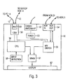
- An IEEE 1394 interface circuit 50 includes a physical interface circuit 64.
- the physical interface circuit 64 is coupled to the PC 14 and to the settop box 11, over the IEEE 1394 serial bus cables 12 and 13, respectively.
- the IEEE 1394 interface circuit 50 is coupled to a CPU 56 for controlling communications between the CPU 56 and devices coupled to the IEEE 1394 serial bus network.
- the IEEE 1394 interface circuit 50 is also coupled to an audio/video switch 55 for providing video signals from the devices coupled to the IEEE 1394 serial bus network.
- a cable/antenna interface circuit 52 is coupled to receive input signals from a coaxial cable or an antenna and to pass those signals through a tuner 53 to an audio/video switch 55.
- a traditional VCR interface circuit 54 is coupled to receive input signals from the VCR 21 and to output signals to the VCR 21.
- the VCR interface circuit 54 is also coupled to the audio/video switch 55 for directing audio/video signals to and from the VCR 21.
- a properly configured VCR 17, capable of communication over the IEEE 1394 serial bus is also coupled to the television 10 through the IEEE 1394 serial bus network.
- An input detection circuit 58 is coupled to the CPU 56 for detecting input signals from the cursor control device 16 and other input devices. Based on signals from the input detection circuit 58 the CPU 56 determines the current placement of the cursor and sends the control signals to the appropriate driving device over the IEEE 1394 serial bus.
- the audio/video switch 55 and the CPU 56 are coupled to the video random access memory (VRAM) circuit 61 for combining windows which are controlled by the PC 14 or other driving devices, with windows featuring live video driven by the television 10 using signals received either from the VCR 21 through the VCR interface circuit 54, the cable/antenna interface circuit 52 or other devices coupled to the television 10 through the IEEE 1394 serial bus.
- the VRAM circuit 61 provides the video signals to the display 62. If a compressed video stream of data is received by the television 10, that stream of data is decompressed before being sent to the VRAM circuit 61 by a coder/decoder circuit (CODEC) or other appropriate decompression engine, within the television 10.
- CDEC coder/decoder circuit
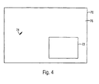
- FIG. 4 An example of a screen 70, including a main display window 76 and a secondary display window 72, is illustrated in Figure 4.
- the main display window 76 is driven by the television 10 itself, from a signal received through the cable interface circuit 52, and the secondary display window 72 is driven by the PC 14.
- the IEEE 1394 interface circuit 50 provides a two-way communication channel between the television 10 and a device driving a display window, in this case the PC 14. Signals from the PC 14, necessary for driving the display window 72 are sent through the IEEE 1394 interface circuit 50 to the VRAM circuit 61, as controlled by the CPU 56.
- the VRAM circuit 61 uses those signals to provide the output video, graphics or text within the display window 72 on the screen 70.
- Control and input signals received by the input detection circuit 58 are used to control the television 10 if the cursor 74 is currently positioned in the main display window 76, which is driven by the television 10. If the cursor 74 is currently positioned within the secondary display window 72, then control and input signals received by the input detection circuit 58 are transmitted through the IEEE 1394 interface circuit 50 to the device driving the secondary display window, in this example, the PC 14.
- Each device which is driving a display window on the television 10 must preferably establish a separate connection, through the IEEE 1394 serial bus network, with the television 10. As stated above, this connection is bidirectional; e.g. once a connection is established the television 10 and the PC 14 send signals to each other.
- a device driving a display window establishes that window by first requesting that the display window be established by the television. When making this request, the driving device specifies characteristics of the display window including x position on the screen, y position on the screen, width, height, color depth and color space. If these characteristics are not specified by the driving device when the request is made, then the television 10 will establish the display window using default parameters.
- the television 10 After receiving a request to establish a display window from a driving device, the television 10 then sends an acknowledging response back to the driving device indicating whether the request was successful or not. If the connection request was successful and the television 10 is able to create a display window, then the acknowledging response contains a handle to the display window, information regarding the characteristics of the display window including the x position, y position, width, height, color depth and color space of the window and an IEEE 1394 offset address to the television display space where the window begins. If the connection was not successful, the response to the driving device includes information regarding the reasons for the failed connection.
- the PC 14 specified a width for the display window which cannot be accommodated by the television 10
- the information within the response includes the width of a display window that could be accommodated by the television 10.
- the PC 14 is then able to adjust its parameters to fit within the available parameters.
- a driving device desires to change a display window which has previously been established, then the driving device sends a change request to the television with the data containing the parameters to be changed. In response to this change request, the television 10 will send an acknowledging response back to the driving device indicating whether or not the display window parameters were successfully changed. If the window parameters were successfully changed, the data contains the new values and the new IEEE 1394 offset address of the display window. If the window parameters were not successfully changed, the data within the response indicates the reason why the request failed.
- a driving device can also change the shape of the pointer or cursor used within the display window on the television 10 which it is controlling, by sending a change cursor request to the television 10.
- This request will include data regarding the window it wants to change the cursor for.
- the television 10 sends a response back to the driving device indicating whether the request failed or succeeded.
- This response indicates the x and y positions of the cursor within the window, the width and height of the cursor, the x and y positions of the hot spot of the cursor and the IEEE 1394 offset address where the cursor begins.
- the driving device then writes the new cursor into that specified IEEE 1394 offset address.
- the television 10 waits for a predetermined period of time before reclaiming its own display area. During this time period, a driving device which was previously controlling a display window can reestablish the connection with the television 10. If the driving device does not reestablish the connection during this time period, the television 10 closes the driving device's window and disconnects from the driving device. To reestablish the connection, a driving device sends the television 10 a unique connection identification number or window handle, which tells the television 10 that the driving device is reestablishing a previous connection. Assuming that the driving device saved the position of that window along with its identification number, the display window will be maintained at the same position as it was before. After receiving a request to reestablish a previous connection, the television 10 will send back a response to the driving device indicating whether or not the connection has been successfully reestablished.
- a disconnect request is sent to the television 10.
- This disconnect request includes the connection identification number.
- the television 10 After receiving a disconnect request, the television 10 sends a disconnect acknowledging response indicating whether or not the disconnect is successful. If the disconnect is not successful, then the driving device repeats the disconnect request until the connection is successfully terminated and the display window is closed.
- input signals can be sent from the cursor control/input device 16 to the driving device through the television 10.
- the input detection circuit 58 detects an input signal and the cursor is positioned within the display window, then the input signal is sent through the IEEE 1394 interface circuit 50 to the driving device over the IEEE 1394 serial bus.
- a driving device can be controlled by a user even when the driving device is not in the same location as the television 10 of the present invention.
- the television 10 and input device 16 of the present invention can therefore be used to control devices throughout a home, school, office or other appropriate environment, which are coupled to the television 10 by an IEEE 1394 serial bus. This control is accomplished by positioning the cursor within a display window on the television 10 driven by an appropriate device and entering control input signals which will be transmitted to the device through the television 10.
- the television 10 with multiple display windows and placement dependent cursor and function control, will display video and graphics inputs from multiple driving devices within appropriate display windows.
- the size of each display window is adjustable to encompass a predetermined amount of the display screen.
- a cursor control and input device is used to control the operation of the television 10 and of the devices driving display windows. When the cursor is positioned within a display window, the cursor control and input device is used to control the operation of and provide input to the device driving that display window, through signals sent from the television to the appropriate device over the IEEE 1394 serial bus.
Abstract
Description
Claims (17)
- A method of displaying input signals on a television (10) having a first driving device comprising the steps of:a. establishing a connection between the television (10) and a second driving device (11, 14, 17, 18, 21);b. opening a display window (72) on the television (10) driven by the second driving device (11, 14, 17, 18, 21), wherein the second driving device drives the display window using control signals sent through the connection ;c. determining a current cursor position (74) on the television (10); andd. receiving input signals through the television (10), transmitting the input signals from the television to the second driving device (11, 14, 17, 18, 21) when the current cursor position (74) is within the display window (72) and transmitting the input signals from the television to the first driving device when the current cursor position (74) is outside the display window (72) yet within the display device (10).
- The method as claimed in claim 1 wherein the first driving device is a local driving device resident within the display device (10) and the second driving device (11, 14, 17, 18, 21) is a remote device not resident within the display device (10).
- The method as claimed in claim 2 wherein the remote driving device is a personal computer (14).
- The method as claimed in claim 3 wherein the connection between the television (10) and a second driving device (11, 14, 17, 18, 21) is established through an IEEE 1394 serial bus (12, 13, 15, 19).
- The method as claimed in claim 2 wherein the remote driving device is a consumer electronics device (11, 14, 17, 18, 21).
- The method as claimed in claim 5 wherein the connection between the television (10) and a second driving device (11, 14, 17, 18, 21) is established through an IEEE 1394 serial bus (12, 13, 15, 19).
- The method as claimed in claim 1 further comprising the step of controlling the cursor position (74) on the television (10) based on input signals.
- The method as claimed in claim 7 wherein the input signals are received from a wireless mouse device (16).
- The method as claimed in claim 7 wherein the input signals are received from a keyboard device (38).
- The method as claimed in claim 8 wherein the connection between the television (10) and the second driving device (11, 14, 17, 18, 21) is established through an IEEE 1394 serial bus (12, 13, 15, 19).
- A television (10) for displaying signals from a plurality of driving devices (11, 14, 17, 18, 21) comprising:a. an interface circuit (12, 13, 15, 19) configured for coupling to said driving devices (11, 14, 17, 18; 21), thereby establishing a connection between the television (10) and said driving devices (11, 14, 17, 18, 21), wherein a display window (72) is opened on the television (10) for each successful connection and controlled by control signals sent through the connection from a corresponding driving device;b. an input detection circuit (58) for determining a current cursor position (74) on the television (10); andd. an input device (16, 38, 40) for providing control signals and input to the television (10), wherein the control signals and input are received by the television and are transmitted from the television (10) to an appropriate one of the driving devices (11, 14, 17, 18, 21) when the current cursor position (74) is within the display window (72) of the driving device.
- The television (10) as claimed in claim 11 wherein the input device (16, 38, 40) is used to control the current cursor position (74).
- The television (10) as claimed in claim 12 wherein the input device (16, 38, 40) is a wireless mouse device (16).
- The television (10) as claimed in claim 12 wherein the input device (16, 38, 40) is a keyboard device (38).
- The television (10) as claimed in claim 13 wherein the interface circuit (12, 13, 15, 19) is an IEEE 1394 serial bus (12, 13, 15, 19) interface circuit (12, 13, 15, 19) and includes an IEEE 1394 physical connection.
- The television (10) as claimed in claim 12 wherein at least one of the driving devices (14, 17, 18) is a remote driving device.
- A display system for displaying video and graphics signals comprising:a. a television (10) according to any one of claims 11 to 16; whereinb. one of the driving devices comprises a personal computer driving device (14) coupled to the television (10) by an IEEE 1394 serial bus (12, 13, 15, 19) for establishing a connection between the television (10) and the personal computer (14), wherein a display window (72) is opened on the television (10) for the personal computer (14).
Priority Applications (1)
| Application Number | Priority Date | Filing Date | Title |
|---|---|---|---|
| EP04012202A EP1453309A1 (en) | 1997-04-03 | 1998-03-31 | Display with one or more display windows and placement dependent cursor and function control |
Applications Claiming Priority (3)
| Application Number | Priority Date | Filing Date | Title |
|---|---|---|---|
| US832490 | 1997-04-03 | ||
| US08/832,490 US6313880B1 (en) | 1997-04-03 | 1997-04-03 | Display with one or more display windows and placement dependent cursor and function control |
| PCT/US1998/006327 WO1998044731A1 (en) | 1997-04-03 | 1998-03-31 | Display with one or more display windows and placement dependent cursor and function control |
Related Child Applications (1)
| Application Number | Title | Priority Date | Filing Date |
|---|---|---|---|
| EP04012202A Division EP1453309A1 (en) | 1997-04-03 | 1998-03-31 | Display with one or more display windows and placement dependent cursor and function control |
Publications (3)
| Publication Number | Publication Date |
|---|---|
| EP0976242A1 EP0976242A1 (en) | 2000-02-02 |
| EP0976242A4 EP0976242A4 (en) | 2002-10-23 |
| EP0976242B1 true EP0976242B1 (en) | 2004-09-15 |
Family
ID=25261804
Family Applications (2)
| Application Number | Title | Priority Date | Filing Date |
|---|---|---|---|
| EP04012202A Ceased EP1453309A1 (en) | 1997-04-03 | 1998-03-31 | Display with one or more display windows and placement dependent cursor and function control |
| EP98913328A Expired - Lifetime EP0976242B1 (en) | 1997-04-03 | 1998-03-31 | Display with one or more display windows and placement dependent cursor and function control |
Family Applications Before (1)
| Application Number | Title | Priority Date | Filing Date |
|---|---|---|---|
| EP04012202A Ceased EP1453309A1 (en) | 1997-04-03 | 1998-03-31 | Display with one or more display windows and placement dependent cursor and function control |
Country Status (8)
| Country | Link |
|---|---|
| US (1) | US6313880B1 (en) |
| EP (2) | EP1453309A1 (en) |
| JP (1) | JP4242455B2 (en) |
| KR (1) | KR100522152B1 (en) |
| AT (1) | ATE276623T1 (en) |
| AU (1) | AU6790598A (en) |
| DE (1) | DE69826258T2 (en) |
| WO (1) | WO1998044731A1 (en) |
Families Citing this family (58)
| Publication number | Priority date | Publication date | Assignee | Title |
|---|---|---|---|---|
| AU9320698A (en) * | 1997-09-18 | 1999-04-05 | Thomson Consumer Electronics, Inc | Digital television apparatus for controlling a peripheral device via a digital bus |
| US6717578B1 (en) * | 1998-02-17 | 2004-04-06 | Sun Microsystems, Inc. | Graphics system with a variable-resolution sample buffer |
| US7603684B1 (en) | 1998-05-19 | 2009-10-13 | United Video Properties, Inc. | Program guide system with video-on-demand browsing |
| TW456148B (en) | 1998-06-16 | 2001-09-21 | United Video Properties Inc | Interactive television program guide with simultaneous watch and record capabilities |
| JP4541476B2 (en) * | 1999-02-19 | 2010-09-08 | キヤノン株式会社 | Multi-image display system and multi-image display method |
| US6856254B1 (en) * | 1999-05-12 | 2005-02-15 | Hitachi, Ltd. | Electronic device, electronic device system control method and electronic device system |
| US6928615B1 (en) * | 1999-07-07 | 2005-08-09 | Netzero, Inc. | Independent internet client object with ad display capabilities |
| US6563547B1 (en) * | 1999-09-07 | 2003-05-13 | Spotware Technologies, Inc. | System and method for displaying a television picture within another displayed image |
| JP2001103393A (en) * | 1999-09-28 | 2001-04-13 | Sony Corp | Receiver and method, and recording medium |
| US7421472B1 (en) * | 1999-11-19 | 2008-09-02 | Ross Jr Robert C | System, method, and computer program product for providing a multi-user e-mail system |
| US6633314B1 (en) | 2000-02-02 | 2003-10-14 | Raja Tuli | Portable high speed internet device integrating cellular telephone and palm top computer |
| US6690403B1 (en) | 2000-02-16 | 2004-02-10 | Raja Tuli | Portable high speed internet device and information on links to web sites |
| US6874009B1 (en) * | 2000-02-16 | 2005-03-29 | Raja Tuli | Portable high speed internet device with user fees |
| US6725268B1 (en) * | 2000-08-11 | 2004-04-20 | At&T Corp. | System and method for providing status information from multiple information sources in a single display |
| US6603517B1 (en) | 2000-06-29 | 2003-08-05 | Koninklijke Philips Electronics N.V. | Very low cost digital TV module |
| US8645856B1 (en) * | 2000-08-04 | 2014-02-04 | Netzero, Inc. | Ticker for internet client |
| US6643124B1 (en) * | 2000-08-09 | 2003-11-04 | Peter J. Wilk | Multiple display portable computing devices |
| US7191211B2 (en) | 2000-10-03 | 2007-03-13 | Raja Tuli | Portable high speed internet access device priority protocol |
| GB0106395D0 (en) * | 2001-03-15 | 2001-05-02 | Pace Micro Tech Plc | Television system |
| KR100747518B1 (en) * | 2001-04-06 | 2007-08-08 | 엘지전자 주식회사 | Apparatus for processing multi screen in digital TV |
| US20030063227A1 (en) * | 2001-10-03 | 2003-04-03 | Whitelaw Jeffrey G. | Integrated modular projection television system |
| US7305357B2 (en) * | 2002-01-24 | 2007-12-04 | Shaw Cablesystems, G.P. | Method and system for providing and controlling delivery of content on-demand over a cable television network and a data network |
| US6842795B2 (en) | 2002-06-10 | 2005-01-11 | Siemens Communications, Inc. | Methods and apparatus for shifting focus between multiple devices |
| US20040027487A1 (en) * | 2002-08-09 | 2004-02-12 | Rzadzki Robert J. | System to provide custom text and graphic information to a television system infrastructure |
| US8176428B2 (en) | 2002-12-03 | 2012-05-08 | Datawind Net Access Corporation | Portable internet access device back page cache |
| EP1439699A1 (en) * | 2002-12-19 | 2004-07-21 | ABB Research Ltd | Arrangement for distributing digital video program information |
| JP2004328658A (en) * | 2003-04-28 | 2004-11-18 | Toshiba Corp | Video display unit and setup method for this video display unit |
| US8302111B2 (en) | 2003-11-24 | 2012-10-30 | Time Warner Cable Inc. | Methods and apparatus for hardware registration in a network device |
| US7266726B1 (en) | 2003-11-24 | 2007-09-04 | Time Warner Cable Inc. | Methods and apparatus for event logging in an information network |
| JP2005181404A (en) * | 2003-12-16 | 2005-07-07 | Nec Viewtechnology Ltd | Image projection controller capable of displaying multiple images |
| US9213538B1 (en) | 2004-02-06 | 2015-12-15 | Time Warner Cable Enterprises Llc | Methods and apparatus for display element management in an information network |
| US7779361B2 (en) * | 2004-02-09 | 2010-08-17 | Malmstrom R Dean | Change-alarmed, integrated console apparatus and method |
| US7353458B2 (en) * | 2004-02-09 | 2008-04-01 | Portalis, Lc | Computer presentation and command integration method |
| US7496846B2 (en) * | 2004-02-09 | 2009-02-24 | Portalis, Lc | Computer presentation and command integration apparatus |
| JP4254573B2 (en) * | 2004-02-27 | 2009-04-15 | 株式会社日立製作所 | Display method and display device |
| JP2006067063A (en) * | 2004-08-25 | 2006-03-09 | Fujitsu Ltd | Switching device, electronic equipment, data transferring method and program for making computer execute the same method |
| CN100422923C (en) * | 2004-11-23 | 2008-10-01 | 国际商业机器公司 | Device and method for enhancing output display of portable apparatus |
| CN100508019C (en) * | 2006-02-23 | 2009-07-01 | 深圳迈瑞生物医疗电子股份有限公司 | Multi channel digital display signal superposition device and method |
| JP2007249476A (en) * | 2006-03-15 | 2007-09-27 | Ricoh Co Ltd | Information processing device and information processing method |
| US8627225B2 (en) * | 2006-06-09 | 2014-01-07 | Honeywell International Inc. | Apparatus and methods for ensuring closure of displays |
| US20080003559A1 (en) * | 2006-06-20 | 2008-01-03 | Microsoft Corporation | Multi-User Multi-Input Application for Education |
| US8199113B2 (en) * | 2006-09-13 | 2012-06-12 | Savant Systems, Llc | Programmable on screen display and remote control |
| US7930644B2 (en) * | 2006-09-13 | 2011-04-19 | Savant Systems, Llc | Programming environment and metadata management for programmable multimedia controller |
| JP2009009330A (en) * | 2007-06-27 | 2009-01-15 | Fujitsu Ltd | Information processor, information processing system and control method for information processor |
| KR101493906B1 (en) * | 2008-08-25 | 2015-02-16 | 삼성전자 주식회사 | Image processing apparatus, display apparatus and method of controlling the display apparatus |
| US20100205631A1 (en) * | 2009-02-06 | 2010-08-12 | Rien Heald | Screen text messaging |
| EP2230839A1 (en) * | 2009-03-17 | 2010-09-22 | Koninklijke Philips Electronics N.V. | Presentation of video content |
| JP5294955B2 (en) * | 2009-04-08 | 2013-09-18 | キヤノン株式会社 | Video processing apparatus and control method thereof |
| US10097890B2 (en) | 2011-03-15 | 2018-10-09 | Sony Corporation | System and method for virtual input and multiple view display |
| JP5427911B2 (en) * | 2012-04-11 | 2014-02-26 | Eizo株式会社 | Cursor movement control method, computer program, cursor movement control device, and image display system |
| US10795535B2 (en) * | 2012-08-28 | 2020-10-06 | Eizo Corporation | Management of multiple display areas |
| KR102058041B1 (en) * | 2012-12-26 | 2019-12-20 | 엘지전자 주식회사 | Image display apparatus, and method for operating the same |
| US20150046962A1 (en) * | 2013-08-12 | 2015-02-12 | SmartQ Technologies Inc. | Method of controlling physically separated network computers in one monitor and security system using the same. |
| US11716558B2 (en) | 2018-04-16 | 2023-08-01 | Charter Communications Operating, Llc | Apparatus and methods for integrated high-capacity data and wireless network services |
| US11129213B2 (en) | 2018-10-12 | 2021-09-21 | Charter Communications Operating, Llc | Apparatus and methods for cell identification in wireless networks |
| US11129171B2 (en) | 2019-02-27 | 2021-09-21 | Charter Communications Operating, Llc | Methods and apparatus for wireless signal maximization and management in a quasi-licensed wireless system |
| US11026205B2 (en) | 2019-10-23 | 2021-06-01 | Charter Communications Operating, Llc | Methods and apparatus for device registration in a quasi-licensed wireless system |
| JP7177803B2 (en) * | 2020-07-08 | 2022-11-24 | シャープ株式会社 | Display device |
Family Cites Families (45)
| Publication number | Priority date | Publication date | Assignee | Title |
|---|---|---|---|---|
| US4622013A (en) * | 1984-05-21 | 1986-11-11 | Interactive Research Corporation | Interactive software training system |
| US5367316A (en) * | 1990-03-27 | 1994-11-22 | Matsushita Electric Industrial Co., Ltd. | Remote-control apparatus for electronics apparatus |
| US5113259A (en) * | 1990-04-19 | 1992-05-12 | Thomson Consumer Electronics, Inc. | Data transfer from an external computer to a television receiver having picture-in-picture capability |
| US5111296A (en) * | 1990-04-19 | 1992-05-05 | Thomson Consumer Electronics, Inc. | Data transfer from a television receiver having picture-in-picture capability to an external computer |
| GB9106113D0 (en) | 1991-03-22 | 1991-05-08 | D2B Systems Co Ltd | Local communication bus system and apparatus for use in such a system |
| US5375199A (en) | 1991-06-04 | 1994-12-20 | Digital Equipment Corporation | System monitoring method and device including a graphical user interface to view and manipulate system information |
| JP3243803B2 (en) | 1991-08-28 | 2002-01-07 | ソニー株式会社 | AV equipment |
| US5500934A (en) | 1991-09-04 | 1996-03-19 | International Business Machines Corporation | Display and control system for configuring and monitoring a complex system |
| JPH0575944A (en) * | 1991-09-10 | 1993-03-26 | Sony Corp | Television receiver |
| KR930007256A (en) * | 1991-09-10 | 1993-04-22 | 오오가 노리오 | A video display device and an television set showing an operation menu |
| JP3198486B2 (en) * | 1992-03-11 | 2001-08-13 | ソニー株式会社 | Monitor system for AV system |
| US5408603A (en) | 1992-03-31 | 1995-04-18 | Dow Benelux N.V. | Global process control information system and method |
| JPH0638128A (en) | 1992-06-19 | 1994-02-10 | Sony Corp | Video image display device |
| US5311302A (en) | 1992-07-02 | 1994-05-10 | Hughes Aircraft Company | Entertainment and data management system for passenger vehicle including individual seat interactive video terminals |
| KR960003880B1 (en) * | 1992-10-12 | 1996-03-23 | 엘지전자주식회사 | Caption display control apparatus and the method thereof |
| JP3302425B2 (en) | 1993-01-29 | 2002-07-15 | パイオニア株式会社 | Selection method and selection device |
| JP3201051B2 (en) | 1993-02-05 | 2001-08-20 | ソニー株式会社 | Remote control system |
| ATE225964T1 (en) * | 1993-03-31 | 2002-10-15 | Luma Corp | INFORMATION MANAGEMENT IN AN ENDOSCOPY SYSTEM |
| US5450140A (en) * | 1993-04-21 | 1995-09-12 | Washino; Kinya | Personal-computer-based video production system |
| US5544315A (en) * | 1993-05-10 | 1996-08-06 | Communication Broadband Multimedia, Inc. | Network multimedia interface |
| US5557724A (en) | 1993-10-12 | 1996-09-17 | Intel Corporation | User interface, method, and apparatus selecting and playing channels having video, audio, and/or text streams |
| GB9325301D0 (en) | 1993-12-10 | 1994-02-16 | D2B Systems Co Ltd | Local communication system and station for use in such a system |
| US5436641A (en) | 1994-03-03 | 1995-07-25 | Cirrus Logic, Inc. | Flexible graphics interface for multiple display modes |
| US5502504A (en) * | 1994-04-28 | 1996-03-26 | Prevue Networks, Inc. | Video mix program guide |
| KR100348915B1 (en) * | 1994-05-12 | 2002-12-26 | 마이크로소프트 코포레이션 | TV program selection method and system |
| US5453796A (en) * | 1994-06-28 | 1995-09-26 | Thomson Consumer Electronics, Inc. | Signal swap apparatus for a television receiver having an HDTV main picture signal processor and an NTSC Pix-in-Pix signal processor |
| JP3520572B2 (en) * | 1994-08-02 | 2004-04-19 | ソニー株式会社 | Input device selection method |
| US5926168A (en) * | 1994-09-30 | 1999-07-20 | Fan; Nong-Qiang | Remote pointers for interactive televisions |
| JP3589720B2 (en) * | 1994-12-07 | 2004-11-17 | 株式会社東芝 | Multi-screen TV receiver |
| JP3536866B2 (en) * | 1994-12-22 | 2004-06-14 | ソニー株式会社 | Video recording / reproducing apparatus and method |
| US5657246A (en) * | 1995-03-07 | 1997-08-12 | Vtel Corporation | Method and apparatus for a video conference user interface |
| JP3498871B2 (en) * | 1995-03-31 | 2004-02-23 | ソニー株式会社 | Television function selection method, television receiver, and remote commander for television receiver |
| US5557338A (en) * | 1995-04-05 | 1996-09-17 | Thomson Consumer Electronics, Inc. | Television receiver using received channel guide information and a secondary video signal processor for displaying secondary channel information |
| JPH08289302A (en) | 1995-04-14 | 1996-11-01 | Toshiba Corp | Image decoding device |
| US5737028A (en) * | 1995-11-01 | 1998-04-07 | International Business Machines Corporation | Previous channel listing with cursor controlled user interface for television video displays |
| US5787259A (en) * | 1996-03-29 | 1998-07-28 | Microsoft Corporation | Digital interconnects of a PC with consumer electronics devices |
| US5850340A (en) * | 1996-04-05 | 1998-12-15 | York; Matthew | Integrated remote controlled computer and television system |
| US5793366A (en) * | 1996-11-12 | 1998-08-11 | Sony Corporation | Graphical display of an animated data stream between devices on a bus |
| US5790201A (en) * | 1996-08-08 | 1998-08-04 | Antos; Jeffrey David | Television and computer capability integration |
| US5847771A (en) * | 1996-08-14 | 1998-12-08 | Bell Atlantic Network Services, Inc. | Digital entertainment terminal providing multiple digital pictures |
| US5844623A (en) * | 1996-09-27 | 1998-12-01 | Sony Corporation | Television with integrated receiver decoder |
| US5999167A (en) * | 1996-11-08 | 1999-12-07 | Stephen A. Marsh | Cursor control device |
| US5819156A (en) * | 1997-01-14 | 1998-10-06 | Compaq Computer Corp. | PC/TV usage tracking and reporting device |
| US5913030A (en) * | 1997-03-18 | 1999-06-15 | International Business Machines Corporation | Method and system for client/server communications with user information revealed as a function of willingness to reveal and whether the information is required |
| US5926207A (en) * | 1997-03-31 | 1999-07-20 | Compaq Computer Corporation | Channel server functionality |
-
1997
- 1997-04-03 US US08/832,490 patent/US6313880B1/en not_active Expired - Lifetime
-
1998
- 1998-03-31 AT AT98913328T patent/ATE276623T1/en not_active IP Right Cessation
- 1998-03-31 JP JP54192498A patent/JP4242455B2/en not_active Expired - Fee Related
- 1998-03-31 KR KR10-1999-7008992A patent/KR100522152B1/en not_active IP Right Cessation
- 1998-03-31 WO PCT/US1998/006327 patent/WO1998044731A1/en active IP Right Grant
- 1998-03-31 EP EP04012202A patent/EP1453309A1/en not_active Ceased
- 1998-03-31 AU AU67905/98A patent/AU6790598A/en not_active Abandoned
- 1998-03-31 EP EP98913328A patent/EP0976242B1/en not_active Expired - Lifetime
- 1998-03-31 DE DE69826258T patent/DE69826258T2/en not_active Expired - Lifetime
Also Published As
| Publication number | Publication date |
|---|---|
| WO1998044731A1 (en) | 1998-10-08 |
| EP0976242A4 (en) | 2002-10-23 |
| ATE276623T1 (en) | 2004-10-15 |
| JP4242455B2 (en) | 2009-03-25 |
| US6313880B1 (en) | 2001-11-06 |
| AU6790598A (en) | 1998-10-22 |
| KR100522152B1 (en) | 2005-10-18 |
| DE69826258D1 (en) | 2004-10-21 |
| JP2001527714A (en) | 2001-12-25 |
| EP0976242A1 (en) | 2000-02-02 |
| EP1453309A1 (en) | 2004-09-01 |
| KR20010005915A (en) | 2001-01-15 |
| DE69826258T2 (en) | 2005-11-17 |
Similar Documents
| Publication | Publication Date | Title |
|---|---|---|
| EP0976242B1 (en) | Display with one or more display windows and placement dependent cursor and function control | |
| JP4642231B2 (en) | Method and apparatus for handling broadband screen display graphics data in a distributed IEEE 1394 network using an isochronous data transmission format | |
| EP1088448B1 (en) | A method of and apparatus for partitioning, scaling and displaying video and/or graphics across several display devices | |
| US20020031333A1 (en) | On-the fly video editing device for capturing and storing images from a video stream during playback for subsequent editing and recording | |
| US6839071B1 (en) | Data communication apparatus and method for receiving and displaying information from first and second devices | |
| US20020057892A1 (en) | Video recording device including the ability to concurrently record and playback | |
| US6191822B1 (en) | Method of and apparatus for separating audio and video data from a combined audio/video stream of data | |
| US20010011310A1 (en) | Method of and apparatus for capturing and processing continuous media-based data streams transmitted over an ieee 1394 serial bus | |
| EP0939529B1 (en) | Destination node, data communication system, method of controlling a destination node and method of operating a data communication system | |
| US7499078B2 (en) | Method of and apparatus for generating a precise frame rate in digital video transmission from a computer system to a digital video device | |
| US7310808B2 (en) | Method of and apparatus for supporting and enabling the selection and mixing of multiple streams of audio/video data from multiple sources within a receiving device allowing external control | |
| US20040189809A1 (en) | Digital imaging apparatus and method for selecting data transfer mode of the same | |
| WO2000062176A1 (en) | System for establishing and maintaining connections and confirming format compatibility between units, subunits and content | |
| JP2001195345A (en) | Communication control method |
Legal Events
| Date | Code | Title | Description |
|---|---|---|---|
| PUAI | Public reference made under article 153(3) epc to a published international application that has entered the european phase |
Free format text: ORIGINAL CODE: 0009012 |
|
| 17P | Request for examination filed |
Effective date: 19991015 |
|
| AK | Designated contracting states |
Kind code of ref document: A1 Designated state(s): AT BE CH DE DK ES FI FR GB GR IE IT LI LU MC NL PT SE |
|
| A4 | Supplementary search report drawn up and despatched |
Effective date: 20020911 |
|
| AK | Designated contracting states |
Kind code of ref document: A4 Designated state(s): AT BE CH DE DK ES FI FR GB GR IE IT LI LU MC NL PT SE |
|
| RIC1 | Information provided on ipc code assigned before grant |
Free format text: 7H 04N 5/45 A, 7H 04N 5/765 B, 7H 04N 7/24 B |
|
| 17Q | First examination report despatched |
Effective date: 20021203 |
|
| GRAP | Despatch of communication of intention to grant a patent |
Free format text: ORIGINAL CODE: EPIDOSNIGR1 |
|
| RAP1 | Party data changed (applicant data changed or rights of an application transferred) |
Owner name: SONY ELECTRONICS INC. |
|
| GRAS | Grant fee paid |
Free format text: ORIGINAL CODE: EPIDOSNIGR3 |
|
| GRAA | (expected) grant |
Free format text: ORIGINAL CODE: 0009210 |
|
| AK | Designated contracting states |
Kind code of ref document: B1 Designated state(s): AT BE CH DE DK ES FI FR GB GR IE IT LI LU MC NL PT SE |
|
| PG25 | Lapsed in a contracting state [announced via postgrant information from national office to epo] |
Ref country code: NL Free format text: LAPSE BECAUSE OF FAILURE TO SUBMIT A TRANSLATION OF THE DESCRIPTION OR TO PAY THE FEE WITHIN THE PRESCRIBED TIME-LIMIT Effective date: 20040915 Ref country code: LI Free format text: LAPSE BECAUSE OF FAILURE TO SUBMIT A TRANSLATION OF THE DESCRIPTION OR TO PAY THE FEE WITHIN THE PRESCRIBED TIME-LIMIT Effective date: 20040915 Ref country code: IT Free format text: LAPSE BECAUSE OF FAILURE TO SUBMIT A TRANSLATION OF THE DESCRIPTION OR TO PAY THE FEE WITHIN THE PRESCRIBED TIME-LIMIT;WARNING: LAPSES OF ITALIAN PATENTS WITH EFFECTIVE DATE BEFORE 2007 MAY HAVE OCCURRED AT ANY TIME BEFORE 2007. THE CORRECT EFFECTIVE DATE MAY BE DIFFERENT FROM THE ONE RECORDED. Effective date: 20040915 Ref country code: FI Free format text: LAPSE BECAUSE OF FAILURE TO SUBMIT A TRANSLATION OF THE DESCRIPTION OR TO PAY THE FEE WITHIN THE PRESCRIBED TIME-LIMIT Effective date: 20040915 Ref country code: CH Free format text: LAPSE BECAUSE OF FAILURE TO SUBMIT A TRANSLATION OF THE DESCRIPTION OR TO PAY THE FEE WITHIN THE PRESCRIBED TIME-LIMIT Effective date: 20040915 Ref country code: BE Free format text: LAPSE BECAUSE OF FAILURE TO SUBMIT A TRANSLATION OF THE DESCRIPTION OR TO PAY THE FEE WITHIN THE PRESCRIBED TIME-LIMIT Effective date: 20040915 Ref country code: AT Free format text: LAPSE BECAUSE OF FAILURE TO SUBMIT A TRANSLATION OF THE DESCRIPTION OR TO PAY THE FEE WITHIN THE PRESCRIBED TIME-LIMIT Effective date: 20040915 |
|
| REG | Reference to a national code |
Ref country code: GB Ref legal event code: FG4D Ref country code: CH Ref legal event code: EP |
|
| REG | Reference to a national code |
Ref country code: IE Ref legal event code: FG4D |
|
| REF | Corresponds to: |
Ref document number: 69826258 Country of ref document: DE Date of ref document: 20041021 Kind code of ref document: P |
|
| PG25 | Lapsed in a contracting state [announced via postgrant information from national office to epo] |
Ref country code: SE Free format text: LAPSE BECAUSE OF FAILURE TO SUBMIT A TRANSLATION OF THE DESCRIPTION OR TO PAY THE FEE WITHIN THE PRESCRIBED TIME-LIMIT Effective date: 20041215 Ref country code: GR Free format text: LAPSE BECAUSE OF FAILURE TO SUBMIT A TRANSLATION OF THE DESCRIPTION OR TO PAY THE FEE WITHIN THE PRESCRIBED TIME-LIMIT Effective date: 20041215 Ref country code: DK Free format text: LAPSE BECAUSE OF FAILURE TO SUBMIT A TRANSLATION OF THE DESCRIPTION OR TO PAY THE FEE WITHIN THE PRESCRIBED TIME-LIMIT Effective date: 20041215 |
|
| PG25 | Lapsed in a contracting state [announced via postgrant information from national office to epo] |
Ref country code: ES Free format text: LAPSE BECAUSE OF FAILURE TO SUBMIT A TRANSLATION OF THE DESCRIPTION OR TO PAY THE FEE WITHIN THE PRESCRIBED TIME-LIMIT Effective date: 20041226 |
|
| PG25 | Lapsed in a contracting state [announced via postgrant information from national office to epo] |
Ref country code: MC Free format text: LAPSE BECAUSE OF NON-PAYMENT OF DUE FEES Effective date: 20050331 Ref country code: LU Free format text: LAPSE BECAUSE OF NON-PAYMENT OF DUE FEES Effective date: 20050331 Ref country code: IE Free format text: LAPSE BECAUSE OF NON-PAYMENT OF DUE FEES Effective date: 20050331 |
|
| REG | Reference to a national code |
Ref country code: CH Ref legal event code: PL |
|
| NLV1 | Nl: lapsed or annulled due to failure to fulfill the requirements of art. 29p and 29m of the patents act | ||
| PLBE | No opposition filed within time limit |
Free format text: ORIGINAL CODE: 0009261 |
|
| STAA | Information on the status of an ep patent application or granted ep patent |
Free format text: STATUS: NO OPPOSITION FILED WITHIN TIME LIMIT |
|
| ET | Fr: translation filed | ||
| 26N | No opposition filed |
Effective date: 20050616 |
|
| REG | Reference to a national code |
Ref country code: IE Ref legal event code: MM4A |
|
| PG25 | Lapsed in a contracting state [announced via postgrant information from national office to epo] |
Ref country code: PT Free format text: LAPSE BECAUSE OF NON-PAYMENT OF DUE FEES Effective date: 20050215 |
|
| PGFP | Annual fee paid to national office [announced via postgrant information from national office to epo] |
Ref country code: FR Payment date: 20130405 Year of fee payment: 16 Ref country code: GB Payment date: 20130327 Year of fee payment: 16 Ref country code: DE Payment date: 20130327 Year of fee payment: 16 |
|
| REG | Reference to a national code |
Ref country code: DE Ref legal event code: R119 Ref document number: 69826258 Country of ref document: DE |
|
| GBPC | Gb: european patent ceased through non-payment of renewal fee |
Effective date: 20140331 |
|
| REG | Reference to a national code |
Ref country code: FR Ref legal event code: ST Effective date: 20141128 |
|
| REG | Reference to a national code |
Ref country code: DE Ref legal event code: R119 Ref document number: 69826258 Country of ref document: DE Effective date: 20141001 |
|
| PG25 | Lapsed in a contracting state [announced via postgrant information from national office to epo] |
Ref country code: FR Free format text: LAPSE BECAUSE OF NON-PAYMENT OF DUE FEES Effective date: 20140331 Ref country code: DE Free format text: LAPSE BECAUSE OF NON-PAYMENT OF DUE FEES Effective date: 20141001 Ref country code: GB Free format text: LAPSE BECAUSE OF NON-PAYMENT OF DUE FEES Effective date: 20140331 |