EP0974940A2 - Apparatus and method for using a transponder as an information buffer - Google Patents
Apparatus and method for using a transponder as an information buffer Download PDFInfo
- Publication number
- EP0974940A2 EP0974940A2 EP99305595A EP99305595A EP0974940A2 EP 0974940 A2 EP0974940 A2 EP 0974940A2 EP 99305595 A EP99305595 A EP 99305595A EP 99305595 A EP99305595 A EP 99305595A EP 0974940 A2 EP0974940 A2 EP 0974940A2
- Authority
- EP
- European Patent Office
- Prior art keywords
- control system
- buffer
- vehicle control
- remote
- communication system
- Prior art date
- Legal status (The legal status is an assumption and is not a legal conclusion. Google has not performed a legal analysis and makes no representation as to the accuracy of the status listed.)
- Withdrawn
Links
Images


Classifications
-
- B—PERFORMING OPERATIONS; TRANSPORTING
- B67—OPENING, CLOSING OR CLEANING BOTTLES, JARS OR SIMILAR CONTAINERS; LIQUID HANDLING
- B67D—DISPENSING, DELIVERING OR TRANSFERRING LIQUIDS, NOT OTHERWISE PROVIDED FOR
- B67D7/00—Apparatus or devices for transferring liquids from bulk storage containers or reservoirs into vehicles or into portable containers, e.g. for retail sale purposes
- B67D7/06—Details or accessories
- B67D7/08—Arrangements of devices for controlling, indicating, metering or registering quantity or price of liquid transferred
- B67D7/14—Arrangements of devices for controlling, indicating, metering or registering quantity or price of liquid transferred responsive to input of recorded programmed information, e.g. on punched cards
- B67D7/145—Arrangements of devices for controlling, indicating, metering or registering quantity or price of liquid transferred responsive to input of recorded programmed information, e.g. on punched cards by wireless communication means, e.g. RF, transponders or the like
-
- G—PHYSICS
- G07—CHECKING-DEVICES
- G07C—TIME OR ATTENDANCE REGISTERS; REGISTERING OR INDICATING THE WORKING OF MACHINES; GENERATING RANDOM NUMBERS; VOTING OR LOTTERY APPARATUS; ARRANGEMENTS, SYSTEMS OR APPARATUS FOR CHECKING NOT PROVIDED FOR ELSEWHERE
- G07C5/00—Registering or indicating the working of vehicles
- G07C5/008—Registering or indicating the working of vehicles communicating information to a remotely located station
-
- G—PHYSICS
- G07—CHECKING-DEVICES
- G07F—COIN-FREED OR LIKE APPARATUS
- G07F13/00—Coin-freed apparatus for controlling dispensing or fluids, semiliquids or granular material from reservoirs
- G07F13/02—Coin-freed apparatus for controlling dispensing or fluids, semiliquids or granular material from reservoirs by volume
- G07F13/025—Coin-freed apparatus for controlling dispensing or fluids, semiliquids or granular material from reservoirs by volume wherein the volume is determined during delivery
Definitions
- the present invention relates to transponders configured to provide an information buffer between a vehicle's communication system and a remote radio frequency communication system, and particularly to such a system associated with fuel dispensers in a fuelling environment.
- POS point-of-sale
- the dispensers include various types of payment means, such as card readers and cash acceptors, to expedite and further enhance fuelling transactions.
- a customer is not limited to the purchase of fuel at the dispenser. More recent dispensers allow the customer to purchase services, such as car washes, and goods, such as fast food or convenience store products at the dispenser. Once purchased, the customer need only pick up the goods and services at the station store or the outlet of a vending machine.
- Remote transaction systems have evolved wherein the fuel dispenser is adapted to communicate with various types of remote communication devices, such as transponders, to provide various types of identification and information to the fuel dispenser automatically.
- remote communication devices such as transponders
- conducting transactions with transponders will be useful to allow the dispenser and fuel station store to monitor the movement of a person carrying a transponder and a vehicle having a transponder, enhance transaction and marketing efficiencies, and improve safety in the fuelling environment.
- transponder applications in a fuelling environment have been limited to the extent that a fuel dispenser is configured to retrieve a customer ID from an interrogator transponder, send that ID to remote host computer to be associated with the customer's debit/credit account and charge the fuelling transaction to the accessed account.
- Many transponders have local user memory areas for use as a scratch pad in future applications. This scratch pad memory area provides the unique ability for the transponder to store various types of information, provide fleet fuelling information, loyalty points, and car wash or other access codes.
- a computer on board an automobile may also provide an interface with the occupants of the automobile just as a personal computer at a home or business provides.
- computers are able to remotely access information, rather than store the information locally. The difficulty arises in determining how an automobile with an on-board computer system can obtain access to the outside world for data network services or other services without a physical connection to the automobile in a cost-effective and widely compatible manner.
- the present invention provides a communications means for facilitating communications between a vehicle control system and a remote communication system, said communications means comprising: receiving means for receiving data from the vehicle control system and/or the remote communications system; and transmitting means for transmitting data received from the vehicle control system to the remote communications systems and/or for transmitting data received from the remote communications system to the vehicle control system, characterised in that the communications means is a transponder buffer for providing asynchronous communication between the vehicle control system and remote communication system, further comprising; a memory for storing data received from the vehicle control system and/or the remote communications system; and control circuitry for storing received data in said memory means wherein said transmitting means transmits data stored in said memory means.
- Adopting the present invention provides a solution to the above discussed problem by transferring information between an automobile and a remote communication system via a transponder buffer capable of communicating with the remote communication system, as well as a vehicle control system.
- the remote communication system is a fuel dispenser or is associated with a fuelling environment, and preferably this is in turn in communication with remote or local data network services.
- the transponder is preferably configured to be mounted on the vehicle and communicates with a vehicle control system electronically or via radio frequency communications.
- the transponder is preferably directly linked to an on-board computer system in the vehicle and configured as a peripheral.
- the term "transponder" is used to define any type of remote communication device providing bidirectional radio communications and should not be limited to classic transponders that modify received signals to generate signals for transmission.
- the transponder is awakened when interrogated by a interrogation device associated with the fuel dispenser.
- the transponder can then recognise that a fuel dispenser is requesting information, such as the customer ID or account information.
- the transponder may send a signal or interrupt to the on-board vehicle control system indicating that a fuel dispenser is requesting the customer ID or information, and the vehicle control system may then signal back to the transponder giving it directions to either respond or not respond.
- the vehicle control system may signal the transponder to send requested information to the fuel dispenser. For instance, if the on-board vehicle control system would like to request that the fuel dispenser download e-mail, the control system will signal the transponder to make that request to the fuel dispenser. If such a request is possible, the fuel dispenser could signal the transponder, which would in turn signal the computer as necessary to communicate the download e-mail.
- a transponder buffer mounted to a vehicle 12 and communicably coupled to a vehicle control system 100.
- the vehicle 12 is shown in a fuelling and retail environment having a plurality of fuel dispensers 14 coupled to a centralized site controller 16, which is in further communication with a host computer or network 18 and a data network server 20.
- the data network server 20 may provide access to various network or Internet services.
- the fuelling environment may also include quick-serve restaurants, car washes and vending facilities, all of which may act as remote communication systems in a fashion similar to that of the fuel dispensers 14 described herein.
- a fuel dispenser 14 is shown constructed according to and as part of the present invention.
- the dispenser provides a fuel delivery path from an underground storage tank (not shown) to the vehicle 12.
- the delivery path includes a fuel delivery line 30 having a fuel metering device 32.
- the fuel delivery line 30 communicates with a fuel delivery hose 34 outside of the dispenser 14 and a delivery nozzle 36.
- the nozzle 36 provides manual control of fuel delivery to the vehicle 12.
- the dispenser 14 also includes a dispenser control system 38 having one or more controllers 39 and associated memory 40.
- the dispenser control system 38 may receive volume data from the metering device 32 through cabling 42 as well as provide control of fuel delivery.
- the dispenser control system 38 may provide audible signals to an audio module and speaker 58 in order to provide various beeps, tones and audible messages to a customer. These messages may include warnings, instructions, advertising, and any other information desired.
- the dispenser 14 is preferably equipped with a payment acceptor, such as a card reader 44 or cash acceptor 46, along with a receipt printer 48.
- a payment acceptor such as a card reader 44 or cash acceptor 46
- the dispenser control system 38 may read data from the magnetic strip of a card inserted in the card reader 44 or receive cash from a customer and communicate such information to the central control system 16 (as shown in Figure 1), such as the G-site controller sold by Gilbarco Inc., 7300 West Friendly Avenue, Greensboro, North Carolina.
- the central control system 16 typically communicates with a remote network host computer 18, such as a card verification authority, to ascertain whether a transaction proposed to be charged to or debited from an account associated with the card inserted in the card reader 44 is authorized.
- the dispenser 14 will include one or more types of displays, preferably one or more alpha-numeric displays 50A together with a high-resolution graphics display 50B.
- the graphics display 50B will generally have an associated key pad 54 adjacent to the display or integrated with the display to provide a touch interface.
- the dispenser may include an additional, auxiliary key pad 56 associated with the card reader 44 for entering secret codes or personal identification numbers (PIN's).
- PIN's personal identification numbers
- the displays 50A,50B and key pads 54,56 may be integrated into a single device and/or touch interface.
- the dispenser control system 38 is preferably comparable to the microprocessor-based control systems used in CRIND (card reader in dispenser) and TRIND (tag or transponder reader in dispenser) type units sold by Gilbarco Inc. under the trademark THE ADVANTAGE.
- the dispenser control system 38 may include or be associated with dispenser communication electronics 52 for providing remote unidirectional or bidirectional communications, preferably RF Communications, between a transponder and the dispenser. These transponders may incorporate Texas Instruments RFID electronics or the Micron Microstamp TM produced by Micron Communications, Inc.. Other radio frequency communication systems are equally acceptable. Additionally, the dispenser 14 may include one or more antennas 59 associated with communications electronics 52.
- fuel dispenser 14 includes a dispenser control system 38, which includes or is associated with a controller 39, memory 40, and communication electronics 52 having a transmitter 60 and receiver 62.
- the communication electronics 52 preferably transmits spread spectrum signals via transmitter 60 and receives backscattered radio frequency signals via receiver 62.
- Vehicle 12 will include a vehicle control system 100 communicably associated with a transponder buffer 10 mounted on the vehicle in a location facilitating communications, and preferably radio frequency communications with the communication electronics associated with the dispenser control system 38.
- the transponder buffer includes basic memory access and communication circuitry 64 cooperating with memory 66 and communication electronics 68.
- Communication electronics include a receiver 70 and transmitter 71 configured to provided remote communications with the communication electronics 52 of the dispenser 14, as well as a receiver 72 and transmitter 73 configured to directly or remotely communicate with the communication electronics 82 of the vehicle control system 100.
- the memory 66 of transponder buffer 10 may have various configurations depending on the embodiment chosen.
- memory 66 may have one message buffer 75 for storing messages transferred from the dispenser 14 to the vehicle control system 100 and from the vehicle control system 100 for the dispenser 14.
- message buffer one 75 may be accompanied by message buffer two 76 wherein one message buffer is used for messages transmitted from the dispenser 14 to be accessed by the vehicle control system 100, and message buffer two 76 is used to store messages transmitted from the vehicle control system 100 for access by the dispenser 14.
- the first embodiment may be preferable when transponder memory is at a minimum while the second embodiment may be preferred when there is sufficient memory to provide simultaneous communications where information may be written to the memory or read therefrom simultaneously by the vehicle control system and the dispenser 14.
- a basic information buffer 74 may be used to store information.
- Buffer 74 may be used to store information such as customer or transponder ID's, account information or other types of information required to establish communications where necessary for quick dispenser access during initial interrogation sequences.
- the memory access and communication control circuitry 64 may access the basic information in the basic information buffer 74 upon initial interrogation and transmit the information to the dispenser 14.
- the dispenser control system 38 may use the basic information (e.g., equipped with a transponder buffer, associated with an intelligent vehicle control system, or communication protocol device type, etc.) to determine the type of transponder, the device's level of sophistication, and how to communicate with the transponder.
- one or more communication flags 77, 78 may be used to alert either the dispenser 14 or vehicle control system 100 to the presence of information in one of the message buffers or the status of a message buffer.
- a dispenser may be configured to only write to a message buffer when a communication flag 77, 78 is set, reset, or contains a specific value.
- the dispenser 14 may set, reset, or change the communication flag 77, 78 upon reading a message from a buffer or writing a message to a buffer.
- the basic memory access and communication control may change the communication flag status upon a successful read or write operation and, optionally, send an acknowledgement that the operation was completed successfully. Preferably, an acknowledgement is only sent during a read operation.
- Another alternative is to read the information that was just written to the buffer to check successful completion of the operation. Furthermore, during any communication flag check or memory access operation, one or more communication flags may be changed by the transponder buffer, dispenser or vehicle control system as necessary, depending on the configuration of those systems.
- the vehicle control system in cooperation with the controller 80, memory 81 and communication electronics 82, may operate in a similar fashion to the dispenser in order to read and write information to the various buffers, check the various communication flags, and provide various types of communications to and through the transponder buffer via the transmitter 83 and receiver 85.
- the vehicle control system 100 may be configured to include random access memory, read-only memory, as well as various registers within or associated with the basic memory access and communication control circuitry 64.
- FIG. 4A and 4B various operational aspects of the invention are shown in conjunction; however, these aspects are considered individually novel.
- the flowcharts depict the operational flow of a vehicle control system, transponder buffer, and dispenser according to the basic concepts of the present invention. Each of the operations begins at blocks B100, T100, and D100, respectively. The specific blocks are referenced in parentheses hereinafter, for improved readability.
- a car having a transponder buffer will enter the fuelling environment and pull up to a fuelling position associated with the fuel dispenser 14. During this time, the dispenser 14 will poll for transponders (block D110) and monitor for the presence of a transponder (block D120).
- the transponder buffer When the transponder buffer becomes within range of the dispenser's interrogation signals, the transponder buffer will receive the interrogation polling signal (block T110) and establish communications by transmitting an initial response to the dispenser (block T120).
- the information transmitted is pulled from the basic information buffer 74 to insure an immediate response during the initial communications between the transponder buffer and the dispenser 14.
- the information may come from one of the message buffers 75, 76 where the information was stored during an earlier communication or information written to the transponder buffer from the vehicle control system upon being interrogated, wherein the vehicle control system wrote information to the transponder message buffer for access by or transmission to the dispenser.
- a signal or interrupt may be sent to the vehicle control system indicating the transponder has been polled (block T130). At that point, the transponder buffer will wait for a response from the dispenser (block T140).
- the dispenser in the meantime will monitor for a response from the transponder (bock D120) and determine whether a transponder has been detected (block D130). If a transponder is not detected, the dispenser 14 will continue to poll for a transponder. If a transponder is detected, the dispenser may request information stored on the transponder (block D140) by transmitting a request to the transponder buffer. The transponder buffer will receive the request from the dispenser (block T150), process the request and transmit a response to the dispenser (block T160). The dispenser 14 will receive the response from the transponder buffer (block D150).
- a vehicle 12 is shown equipped with an "intelligent" vehicle controller 100 providing interactive multimedia access for the driver and the passengers via the transponder buffer 10.
- the intelligent vehicle controller 100 hereinafter referred as the IVC, is designed to provide bi-directional access via various communication systems and networks to systems and people apart from the vehicle.
- the IVC may provide an interactive communication medium allowing customers to interface remote systems to receive advertising and merchandising indicia and, in return, order and provide payment for selected items from within the vehicle.
- the IVC may also facilitate monitoring, reconfiguration and transfer of various types of vehicle data, such as operational, diagnostic or emission information.
- the IVC 100 may be permanently integrated in the vehicle interior with vehicle's electronic system or be configured to removably interface with the electronic system and remain portable between vehicles. In a portable configuration, an interface or docking station 102 is preferable to couple the IVC 100 to the transponder buffer and any desired vehicle systems.
- the vehicle shown in Figure 5 is equipped with an IVC 100 coupled to an occupant interface 102 via a vehicle mounted docking interface 118.
- the docking interface 118 is preferably coupled via a bus or wiring network 104 to various vehicle systems and/or sensors 106-112.
- the IVC 100 either directly or through the docking interface 118 and/or the network 104 will interface with any necessary electronics.
- the IVC 100 may also either directly or indirectly cooperate with the vehicle's fuelling system 114, including any onboard recovery vapour recovery (ORVR) equipment.
- ORVR onboard recovery vapour recovery
- the IVC may have separate processing capability or share processing capability with the another vehicle control system, depending on the amount of integration and the configuration of the IVC and vehicle.
- the IVC 100 may include the occupant interface 102, which may also be associated with a card reader or biometric reader 124, a user input means, such as a keypad, mouse or touch screen electronics 120, a video display 122, a card reader 124, and a printer 126. These features cooperate to provide a basic multimedia interface and means for paying for items ordered through the IVC 100. Additionally, the IVC may include or be associated with an audio system 128, microphone 130 and speaker 132 for providing a bi-directional audio intercom with a corresponding remote system, such as a quick-serve restaurant.
- a camera 134 may be provided to receive images of the vehicle's occupants to enhance an audio intercom system with one or two direction video. With such a system, an order entry operator at a quick-serve restaurant and the vehicle occupant would be able to see and hear each other during order placement.
- a biometric reader 150 may also be coupled to the IVC to provide additional authorization or identification means for vehicle occupants.
- the biometric reader 150 may read the occupant's fingerprints, voice print, retinal scan or other biometric indicia to provide a substantially secure authorization.
- authorization or identification is preferably used in cooperation with financial information stored in the IVC or retrieved via the card reader 124.
- Biometric templates corresponding to the authorized card holder or occupant may be stored on a card read by the card reader, in the IVC remote system or on a network for comparison with the actual biometric indicia provided by the biometric reader 150.
- the IVC (or basic vehicle control system) 100 will be capable of controlling various engine functions 152, diagnostic systems 154, emission systems 156, and any number of auxiliary functions 158 or miscellaneous sensors 160.
- the control system may also interact with the vehicle security system 162, on-board vapour recovery equipment 164, fuel status sensors 166, and trip-related features and functions 168.
- information relating the amount of fuel, the size of the vehicle fuel tank and the type of the vehicle fuel tank may be transferred onto the fuel station store or fuel dispenser. This information may be used to control robotic or automatic fuelling, and tailor a fuelling operation to a particular vehicle in order to maximize delivery rates, fuel quality or octane levels.
- the fuelling information may include quantity, ullage, quality or octane readings.
- the vehicle control system will monitor for transponder activity or receive information from the transponder buffer (block V110) and determine if transponder activity has been detected (block V120). Once transponder activity is detected, the vehicle control system prepares for communications with the dispenser through the transponder buffer. Similarly, the dispenser 14 may communicate with the vehicle control system through the transponder buffer. Up to this point, the dispenser has established communications and may have received information that was stored on the transponder buffer. In this example, information has not been transferred from the vehicle control system to the dispenser or from the dispenser to the vehicle control system.
- the vehicle control system and dispenser interact with the transponder buffer in like fashion.
- both the vehicle control system and dispenser basically write and read information to and from the transponder buffer in cooperation with the other system.
- the dispenser may decide to write or read information to or from the transponder buffer and will preferably check a communication flag (block D160) and transmit a communication flag check signal to the transponder buffer.
- the transponder buffer will receive the communication flag status check signal (block T170) and transmit the communication flag status (block T180) back to the dispenser.
- the dispenser will receive the response from the transponder buffer regarding the communication flag status (block D170) and determine whether it is proper to read information from the buffer or write information to the transponder buffer (block D180). If the flags indicate it is not proper to read or write to the transponder, the communication flags may be checked periodically. If the communication flags are configured for a read or write operation, either a message is written to the transponder buffer or a request to read a message from the buffer is transmitted to the transponder buffer (block D190). The transponder buffer will receive the message or request (block T190).
- the message will be stored in one of the message buffers; if a read request was received, the message in the buffer will be transmitted back to the dispenser (block T200). If a message was written to the buffer, an acknowledgement may be sent back to the dispenser.
- the dispenser will receive the message or an acknowledgement from the transponder buffer (block D200) accordingly, and determine whether or not another read or write operation is necessary (block D210) wherein the process either repeats if further communications are required, or the process comes to an end (block 99).
- the vehicle control system may start the communication process by checking communication flags (block V130), receiving a response regarding the communication flag status from the transponder buffer (block V140), and determining whether it is proper to read or write to the transponder (block V150). Assuming a read or write function is proper, a message is sent to the transponder buffer or a request to read information in the buffer is sent to the transponder buffer (block V160). The vehicle control system will receive a message back (on a read command) or receive an acknowledgement from the transponder buffer (on a write command). During the communications, the transponder buffer is substantially acting in the same way with the vehicle control system as it did in the dispenser control system as discussed above.
- the one or more communication flags may be changed to indicate a change in transponder status or indicate memory is ready for a read or write command.
- the transponder will independently be able to establish its presence to the dispenser, but will not handle any requests until the on-board vehicle control system directs it to do so.
- the dispenser may request the customer ID to begin authorization of a fuelling process.
- the transponder may send a message onto a data bus or directly to the on-board vehicle control system.
- the on-board vehicle control system may allow a customer to preselect whether automatic authorization or manual authorization is desired. If the configuration is for automatic authorization, then the vehicle control system may either send the customer ID to the transponder to be sent to the fuel dispenser, or the vehicle control system may simply give permission to the transponder to send its stored customer ID to the fuel dispenser. By sending such information to the dispenser, the transponder may actually transmit information received by the vehicle control system automatically or simply provide the dispenser access to the information as described above.
- the fuel dispenser will typically send the customer ID to the central site controller 16, which will in turn send it to the host network 18 to be associated with a customer's debit/credit card or account.
- various account information may be transmitted from the transponder buffer or from the vehicle control system in a fashion similar to the customer ID.
- the host computer will authorize the transaction, if such action is proper, and provide sufficient information to the fuel dispenser to allow dispensing of fuel to the vehicle.
- customers may be allowed to dispense fuel while authorization is in progress or may require authorization prior to dispensing fuel.
- any peripherals that are connected to the vehicle control system may communicate with any services or data networks that are connected to the fuel dispenser and/or site controller 16 via the transponder buffer, such as e-mail retrieval for example.
Abstract
A transponder buffer (10) is provided facilitating data transfer between a remote
communication system (14), such as a fuel dispenser, and a vehicle control system (100).
Information written to the transponder memory from remote communication system may
be sent to or retrieved by the vehicle control system. The transponder may include
sufficient communication electronics, memory access and communication control
circuitry, and memory to allow storing of information and access to information by both
the vehicle control system and the fuel dispenser.
Description
- The present invention relates to transponders configured to provide an information buffer between a vehicle's communication system and a remote radio frequency communication system, and particularly to such a system associated with fuel dispensers in a fuelling environment.
- In recent years, traditional gasoline pumps and service stations have evolved into elaborate point-of-sale (POS) devices having sophisticated control electronics and user interfaces with large displays and touch-pads or screens. The dispensers include various types of payment means, such as card readers and cash acceptors, to expedite and further enhance fuelling transactions. A customer is not limited to the purchase of fuel at the dispenser. More recent dispensers allow the customer to purchase services, such as car washes, and goods, such as fast food or convenience store products at the dispenser. Once purchased, the customer need only pick up the goods and services at the station store or the outlet of a vending machine.
- Remote transaction systems have evolved wherein the fuel dispenser is adapted to communicate with various types of remote communication devices, such as transponders, to provide various types of identification and information to the fuel dispenser automatically. Given the sophistication of these transaction systems and the numerous choices provided to the customer at the dispenser, conducting transactions with transponders will be useful to allow the dispenser and fuel station store to monitor the movement of a person carrying a transponder and a vehicle having a transponder, enhance transaction and marketing efficiencies, and improve safety in the fuelling environment.
- Currently, transponder applications in a fuelling environment have been limited to the extent that a fuel dispenser is configured to retrieve a customer ID from an interrogator transponder, send that ID to remote host computer to be associated with the customer's debit/credit account and charge the fuelling transaction to the accessed account. Many transponders have local user memory areas for use as a scratch pad in future applications. This scratch pad memory area provides the unique ability for the transponder to store various types of information, provide fleet fuelling information, loyalty points, and car wash or other access codes.
- While the petroleum industry is working to provide remote communications to customers and their vehicles, there is an increasing effort by automotive manufacturers to provide on-board computer systems for electronic control and diagnostics. A computer on board an automobile may also provide an interface with the occupants of the automobile just as a personal computer at a home or business provides. With the increasing amount of data network services, computers are able to remotely access information, rather than store the information locally. The difficulty arises in determining how an automobile with an on-board computer system can obtain access to the outside world for data network services or other services without a physical connection to the automobile in a cost-effective and widely compatible manner.
- The present invention provides a communications means for facilitating communications between a vehicle control system and a remote communication system, said communications means comprising: receiving means for receiving data from the vehicle control system and/or the remote communications system; and transmitting means for transmitting data received from the vehicle control system to the remote communications systems and/or for transmitting data received from the remote communications system to the vehicle control system, characterised in that the communications means is a transponder buffer for providing asynchronous communication between the vehicle control system and remote communication system, further comprising; a memory for storing data received from the vehicle control system and/or the remote communications system; and control circuitry for storing received data in said memory means wherein said transmitting means transmits data stored in said memory means.
- Adopting the present invention provides a solution to the above discussed problem by transferring information between an automobile and a remote communication system via a transponder buffer capable of communicating with the remote communication system, as well as a vehicle control system. Preferably, the remote communication system is a fuel dispenser or is associated with a fuelling environment, and preferably this is in turn in communication with remote or local data network services.
- The transponder is preferably configured to be mounted on the vehicle and communicates with a vehicle control system electronically or via radio frequency communications. The transponder is preferably directly linked to an on-board computer system in the vehicle and configured as a peripheral. The term "transponder" is used to define any type of remote communication device providing bidirectional radio communications and should not be limited to classic transponders that modify received signals to generate signals for transmission.
- Employing the present invention it is possible to configure a system such that whenever an automobile pulls up to the fuel dispenser, the transponder is awakened when interrogated by a interrogation device associated with the fuel dispenser. The transponder can then recognise that a fuel dispenser is requesting information, such as the customer ID or account information. The transponder may send a signal or interrupt to the on-board vehicle control system indicating that a fuel dispenser is requesting the customer ID or information, and the vehicle control system may then signal back to the transponder giving it directions to either respond or not respond.
- In addition to the fuelling process, the vehicle control system may signal the transponder to send requested information to the fuel dispenser. For instance, if the on-board vehicle control system would like to request that the fuel dispenser download e-mail, the control system will signal the transponder to make that request to the fuel dispenser. If such a request is possible, the fuel dispenser could signal the transponder, which would in turn signal the computer as necessary to communicate the download e-mail.
- One embodiment of the present invention will now be described, by way of example only, with reference to the accompanying drawings, like reference numerals being used to indicate like parts throughout the drawing, of which:
- FIGURE 1 is a schematic of a fuelling environment;
- FIGURE 2 is a schematic of a fuel dispenser;
- FIGURE 3 is a block diagram of a fuel dispenser and a vehicle having a vehicle control system and a transponder buffer;
- FIGURES 4A and 4B are a flow chart representing various basic modes of operation of a transponder buffer in cooperation with a vehicle control system and a fuel dispenser;
- FIGURE 5 is a block diagram of a vehicle having a transponder buffer and other peripheral devices; and
- FIGURE 6 is a block diagram of a complex vehicle control system and an associated transponder buffer.
-
- As best seen in Figure 1, a transponder buffer, generally designated 10, is shown mounted to a
vehicle 12 and communicably coupled to avehicle control system 100. Thevehicle 12 is shown in a fuelling and retail environment having a plurality offuel dispensers 14 coupled to a centralizedsite controller 16, which is in further communication with a host computer ornetwork 18 and adata network server 20. Thedata network server 20 may provide access to various network or Internet services. The fuelling environment may also include quick-serve restaurants, car washes and vending facilities, all of which may act as remote communication systems in a fashion similar to that of thefuel dispensers 14 described herein. - As best seen in Figure 2, a
fuel dispenser 14 is shown constructed according to and as part of the present invention. The dispenser provides a fuel delivery path from an underground storage tank (not shown) to thevehicle 12. The delivery path includes afuel delivery line 30 having a fuel metering device 32. Thefuel delivery line 30 communicates with afuel delivery hose 34 outside of thedispenser 14 and adelivery nozzle 36. Thenozzle 36 provides manual control of fuel delivery to thevehicle 12. - The
dispenser 14 also includes adispenser control system 38 having one ormore controllers 39 and associatedmemory 40. Thedispenser control system 38 may receive volume data from the metering device 32 through cabling 42 as well as provide control of fuel delivery. Thedispenser control system 38 may provide audible signals to an audio module andspeaker 58 in order to provide various beeps, tones and audible messages to a customer. These messages may include warnings, instructions, advertising, and any other information desired. - The
dispenser 14 is preferably equipped with a payment acceptor, such as acard reader 44 orcash acceptor 46, along with areceipt printer 48. With these options, thedispenser control system 38 may read data from the magnetic strip of a card inserted in thecard reader 44 or receive cash from a customer and communicate such information to the central control system 16 (as shown in Figure 1), such as the G-site controller sold by Gilbarco Inc., 7300 West Friendly Avenue, Greensboro, North Carolina. Thecentral control system 16 typically communicates with a remotenetwork host computer 18, such as a card verification authority, to ascertain whether a transaction proposed to be charged to or debited from an account associated with the card inserted in thecard reader 44 is authorized. - The
dispenser 14 will include one or more types of displays, preferably one or more alpha-numeric displays 50A together with a high-resolution graphics display 50B. Thegraphics display 50B will generally have an associatedkey pad 54 adjacent to the display or integrated with the display to provide a touch interface. The dispenser may include an additional,auxiliary key pad 56 associated with thecard reader 44 for entering secret codes or personal identification numbers (PIN's). Notably, thedisplays key pads dispenser control system 38 is preferably comparable to the microprocessor-based control systems used in CRIND (card reader in dispenser) and TRIND (tag or transponder reader in dispenser) type units sold by Gilbarco Inc. under the trademark THE ADVANTAGE. - As noted, the
dispenser control system 38 may include or be associated withdispenser communication electronics 52 for providing remote unidirectional or bidirectional communications, preferably RF Communications, between a transponder and the dispenser. These transponders may incorporate Texas Instruments RFID electronics or the Micron Microstamp™ produced by Micron Communications, Inc.. Other radio frequency communication systems are equally acceptable. Additionally, thedispenser 14 may include one ormore antennas 59 associated withcommunications electronics 52. - Turning now to Figure 3, the basic structure of the
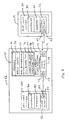
vehicle control system 100,transponder buffer 10, andfuel dispenser 14 are shown. As noted above,fuel dispenser 14 includes adispenser control system 38, which includes or is associated with acontroller 39,memory 40, andcommunication electronics 52 having atransmitter 60 and receiver 62. Thecommunication electronics 52 preferably transmits spread spectrum signals viatransmitter 60 and receives backscattered radio frequency signals via receiver 62. -
Vehicle 12 will include avehicle control system 100 communicably associated with atransponder buffer 10 mounted on the vehicle in a location facilitating communications, and preferably radio frequency communications with the communication electronics associated with thedispenser control system 38. The transponder buffer includes basic memory access andcommunication circuitry 64 cooperating withmemory 66 andcommunication electronics 68. Communication electronics include areceiver 70 andtransmitter 71 configured to provided remote communications with thecommunication electronics 52 of thedispenser 14, as well as areceiver 72 andtransmitter 73 configured to directly or remotely communicate with thecommunication electronics 82 of thevehicle control system 100. - The
memory 66 oftransponder buffer 10 may have various configurations depending on the embodiment chosen. For example,memory 66 may have onemessage buffer 75 for storing messages transferred from thedispenser 14 to thevehicle control system 100 and from thevehicle control system 100 for thedispenser 14. Alternatively, message buffer one 75 may be accompanied by message buffer two 76 wherein one message buffer is used for messages transmitted from thedispenser 14 to be accessed by thevehicle control system 100, and message buffer two 76 is used to store messages transmitted from thevehicle control system 100 for access by thedispenser 14. The first embodiment may be preferable when transponder memory is at a minimum while the second embodiment may be preferred when there is sufficient memory to provide simultaneous communications where information may be written to the memory or read therefrom simultaneously by the vehicle control system and thedispenser 14. - In yet another embodiment, having one, two or more message buffers, a
basic information buffer 74 may be used to store information.Buffer 74 may be used to store information such as customer or transponder ID's, account information or other types of information required to establish communications where necessary for quick dispenser access during initial interrogation sequences. In this embodiment, the memory access andcommunication control circuitry 64 may access the basic information in thebasic information buffer 74 upon initial interrogation and transmit the information to thedispenser 14. Thedispenser control system 38 may use the basic information (e.g., equipped with a transponder buffer, associated with an intelligent vehicle control system, or communication protocol device type, etc.) to determine the type of transponder, the device's level of sophistication, and how to communicate with the transponder. - To further facilitate communications, one or
more communication flags dispenser 14 orvehicle control system 100 to the presence of information in one of the message buffers or the status of a message buffer. For example, a dispenser may be configured to only write to a message buffer when acommunication flag dispenser 14 may set, reset, or change thecommunication flag - The vehicle control system, in cooperation with the
controller 80,memory 81 andcommunication electronics 82, may operate in a similar fashion to the dispenser in order to read and write information to the various buffers, check the various communication flags, and provide various types of communications to and through the transponder buffer via thetransmitter 83 andreceiver 85. - Given the known presence of the transponder buffer to the
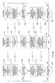
vehicle control system 100, additional control over thetransponder buffer 10 may be exerted by the vehicle control system. This control may be exerted in a way to eliminate the need for one, two or all of the communication flags because the vehicle control system will know when information is successfully written to a buffer, read from a buffer, and/or when the dispenser is working through the transponder buffer. For example, if thedispenser 14 polls thetransponder buffer 10, a signal or interrupt may be sent to thevehicle control system 100. Alternatively, thevehicle control system 100 may periodically poll the transponder buffer to detect dispenser activity using the various communication flags, thereby checking the buffer for message content or checking other status registers. Preferably, thememory 64 is configured to include random access memory, read-only memory, as well as various registers within or associated with the basic memory access andcommunication control circuitry 64. - With reference to the flowcharts of Figures 4A and 4B, various operational aspects of the invention are shown in conjunction; however, these aspects are considered individually novel. The flowcharts depict the operational flow of a vehicle control system, transponder buffer, and dispenser according to the basic concepts of the present invention. Each of the operations begins at blocks B100, T100, and D100, respectively. The specific blocks are referenced in parentheses hereinafter, for improved readability. At some point, a car having a transponder buffer will enter the fuelling environment and pull up to a fuelling position associated with the
fuel dispenser 14. During this time, thedispenser 14 will poll for transponders (block D110) and monitor for the presence of a transponder (block D120). When the transponder buffer becomes within range of the dispenser's interrogation signals, the transponder buffer will receive the interrogation polling signal (block T110) and establish communications by transmitting an initial response to the dispenser (block T120). Preferably, the information transmitted is pulled from thebasic information buffer 74 to insure an immediate response during the initial communications between the transponder buffer and thedispenser 14. However, the information may come from one of the message buffers 75, 76 where the information was stored during an earlier communication or information written to the transponder buffer from the vehicle control system upon being interrogated, wherein the vehicle control system wrote information to the transponder message buffer for access by or transmission to the dispenser. However, it is preferable to have sufficient information stored on the transponder to quickly establish communications with the dispenser upon initial interrogation. - Once the transponder buffer transmits the initial response to the dispenser (at block T120), a signal or interrupt may be sent to the vehicle control system indicating the transponder has been polled (block T130). At that point, the transponder buffer will wait for a response from the dispenser (block T140).
- The dispenser in the meantime will monitor for a response from the transponder (bock D120) and determine whether a transponder has been detected (block D130). If a transponder is not detected, the
dispenser 14 will continue to poll for a transponder. If a transponder is detected, the dispenser may request information stored on the transponder (block D140) by transmitting a request to the transponder buffer. The transponder buffer will receive the request from the dispenser (block T150), process the request and transmit a response to the dispenser (block T160). Thedispenser 14 will receive the response from the transponder buffer (block D150). - Referring now to Figure 5, a
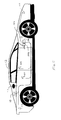
vehicle 12 is shown equipped with an "intelligent"vehicle controller 100 providing interactive multimedia access for the driver and the passengers via thetransponder buffer 10. Theintelligent vehicle controller 100, hereinafter referred as the IVC, is designed to provide bi-directional access via various communication systems and networks to systems and people apart from the vehicle. The IVC may provide an interactive communication medium allowing customers to interface remote systems to receive advertising and merchandising indicia and, in return, order and provide payment for selected items from within the vehicle. The IVC may also facilitate monitoring, reconfiguration and transfer of various types of vehicle data, such as operational, diagnostic or emission information. - The
IVC 100 may be permanently integrated in the vehicle interior with vehicle's electronic system or be configured to removably interface with the electronic system and remain portable between vehicles. In a portable configuration, an interface ordocking station 102 is preferable to couple theIVC 100 to the transponder buffer and any desired vehicle systems. - The vehicle shown in Figure 5 is equipped with an
IVC 100 coupled to anoccupant interface 102 via a vehicle mounteddocking interface 118. Thedocking interface 118 is preferably coupled via a bus orwiring network 104 to various vehicle systems and/or sensors 106-112. TheIVC 100 either directly or through thedocking interface 118 and/or thenetwork 104 will interface with any necessary electronics. TheIVC 100 may also either directly or indirectly cooperate with the vehicle's fuellingsystem 114, including any onboard recovery vapour recovery (ORVR) equipment. Thus, the IVC may have separate processing capability or share processing capability with the another vehicle control system, depending on the amount of integration and the configuration of the IVC and vehicle. - As shown in Figure 6, the
IVC 100 may include theoccupant interface 102, which may also be associated with a card reader orbiometric reader 124, a user input means, such as a keypad, mouse ortouch screen electronics 120, avideo display 122, acard reader 124, and aprinter 126. These features cooperate to provide a basic multimedia interface and means for paying for items ordered through theIVC 100. Additionally, the IVC may include or be associated with anaudio system 128,microphone 130 andspeaker 132 for providing a bi-directional audio intercom with a corresponding remote system, such as a quick-serve restaurant. - A camera 134 may be provided to receive images of the vehicle's occupants to enhance an audio intercom system with one or two direction video. With such a system, an order entry operator at a quick-serve restaurant and the vehicle occupant would be able to see and hear each other during order placement.
- A
biometric reader 150 may also be coupled to the IVC to provide additional authorization or identification means for vehicle occupants. Thebiometric reader 150 may read the occupant's fingerprints, voice print, retinal scan or other biometric indicia to provide a substantially secure authorization. Such authorization or identification is preferably used in cooperation with financial information stored in the IVC or retrieved via thecard reader 124. Biometric templates corresponding to the authorized card holder or occupant may be stored on a card read by the card reader, in the IVC remote system or on a network for comparison with the actual biometric indicia provided by thebiometric reader 150. - It is also envisioned that the IVC (or basic vehicle control system) 100 will be capable of controlling various engine functions 152,
diagnostic systems 154,emission systems 156, and any number ofauxiliary functions 158 ormiscellaneous sensors 160. The control system may also interact with thevehicle security system 162, on-boardvapour recovery equipment 164,fuel status sensors 166, and trip-related features and functions 168. - With respect to fuelling, information relating the amount of fuel, the size of the vehicle fuel tank and the type of the vehicle fuel tank may be transferred onto the fuel station store or fuel dispenser. This information may be used to control robotic or automatic fuelling, and tailor a fuelling operation to a particular vehicle in order to maximize delivery rates, fuel quality or octane levels. The fuelling information may include quantity, ullage, quality or octane readings.
- As noted, the vehicle control system will monitor for transponder activity or receive information from the transponder buffer (block V110) and determine if transponder activity has been detected (block V120). Once transponder activity is detected, the vehicle control system prepares for communications with the dispenser through the transponder buffer. Similarly, the
dispenser 14 may communicate with the vehicle control system through the transponder buffer. Up to this point, the dispenser has established communications and may have received information that was stored on the transponder buffer. In this example, information has not been transferred from the vehicle control system to the dispenser or from the dispenser to the vehicle control system. - Message transfer between these systems is outlined in the portion of the flowcharts shown in Figure 4B. In the preferred embodiment, the vehicle control system and dispenser interact with the transponder buffer in like fashion. Although the communication type and protocols may differ, both the vehicle control system and dispenser basically write and read information to and from the transponder buffer in cooperation with the other system. Initially, the dispenser may decide to write or read information to or from the transponder buffer and will preferably check a communication flag (block D160) and transmit a communication flag check signal to the transponder buffer.
- The transponder buffer will receive the communication flag status check signal (block T170) and transmit the communication flag status (block T180) back to the dispenser. The dispenser will receive the response from the transponder buffer regarding the communication flag status (block D170) and determine whether it is proper to read information from the buffer or write information to the transponder buffer (block D180). If the flags indicate it is not proper to read or write to the transponder, the communication flags may be checked periodically. If the communication flags are configured for a read or write operation, either a message is written to the transponder buffer or a request to read a message from the buffer is transmitted to the transponder buffer (block D190). The transponder buffer will receive the message or request (block T190).
- If the message is written to the buffer, the message will be stored in one of the message buffers; if a read request was received, the message in the buffer will be transmitted back to the dispenser (block T200). If a message was written to the buffer, an acknowledgement may be sent back to the dispenser. The dispenser will receive the message or an acknowledgement from the transponder buffer (block D200) accordingly, and determine whether or not another read or write operation is necessary (block D210) wherein the process either repeats if further communications are required, or the process comes to an end (block 99).
- In similar fashion, the vehicle control system may start the communication process by checking communication flags (block V130), receiving a response regarding the communication flag status from the transponder buffer (block V140), and determining whether it is proper to read or write to the transponder (block V150). Assuming a read or write function is proper, a message is sent to the transponder buffer or a request to read information in the buffer is sent to the transponder buffer (block V160). The vehicle control system will receive a message back (on a read command) or receive an acknowledgement from the transponder buffer (on a write command). During the communications, the transponder buffer is substantially acting in the same way with the vehicle control system as it did in the dispenser control system as discussed above. Upon any read or write command, from either the vehicle control system or the dispenser, additional signals from the vehicle control system, dispenser control system, or internally from the access and
communication control circuitry 70 of thetransponder buffer 10, the one or more communication flags may be changed to indicate a change in transponder status or indicate memory is ready for a read or write command. - Preferably, the transponder will independently be able to establish its presence to the dispenser, but will not handle any requests until the on-board vehicle control system directs it to do so. Once communications are established with the dispenser, the dispenser may request the customer ID to begin authorization of a fuelling process. The transponder may send a message onto a data bus or directly to the on-board vehicle control system. The on-board vehicle control system may allow a customer to preselect whether automatic authorization or manual authorization is desired. If the configuration is for automatic authorization, then the vehicle control system may either send the customer ID to the transponder to be sent to the fuel dispenser, or the vehicle control system may simply give permission to the transponder to send its stored customer ID to the fuel dispenser. By sending such information to the dispenser, the transponder may actually transmit information received by the vehicle control system automatically or simply provide the dispenser access to the information as described above.
- The fuel dispenser will typically send the customer ID to the
central site controller 16, which will in turn send it to thehost network 18 to be associated with a customer's debit/credit card or account. Optionally, various account information may be transmitted from the transponder buffer or from the vehicle control system in a fashion similar to the customer ID. The host computer will authorize the transaction, if such action is proper, and provide sufficient information to the fuel dispenser to allow dispensing of fuel to the vehicle. Depending on site configuration, customers may be allowed to dispense fuel while authorization is in progress or may require authorization prior to dispensing fuel. - Once the fuelling process has been initiated, additional communications may occur between the vehicle and fuel dispenser. Effectively, any peripherals that are connected to the vehicle control system may communicate with any services or data networks that are connected to the fuel dispenser and/or
site controller 16 via the transponder buffer, such as e-mail retrieval for example. - Certain modifications and improvements within the scope of the following claims will occur to those skilled in the art upon reading the foregoing description.
Claims (14)
- A communications means (10) for facilitating communications between a vehicle control system (100) and a remote communication system (14), said communications means (10) comprising:characterised in that the communications means (10) is a transponder buffer for providing asynchronous communication between the vehicle control system (100) and remote communication system (14), further comprising;(a) receiving means (72) for receiving data from the vehicle control system (100) and/or the remote communications system (14); and(b) transmitting means (71,73) for transmitting data received from the vehicle control system (100) to the remote communications systems (14) and/or for transmitting data received from the remote communications system to the vehicle control system (100),wherein said transmitting means (71, 73) transmits data stored in said memory means.(c) a memory (66) for storing data received from the vehicle control system and/or the remote communications system; and(d) control circuitry (64) for storing received data in said memory (66)
- A buffer as claimed in Claim 1 further comprising means for mounting the buffer to the vehicle.
- A buffer as claimed in Claim 2 wherein said means for mounting comprises a housing for the buffer.
- The buffer of any preceding claim wherein said control circuitry (64) is adapted to transmit a message received from the vehicle control system and stored in said memory (66) to the remote communication system upon receiving a signal for retrieving the message from the remote communication system.
- The buffer of any preceding wherein said control circuitry (64) is adapted to transmit a message received from the remote communication system and stored in said memory (66) to the vehicle control system upon receiving a signal for retrieving the message from the vehicle control system.
- The transponder buffer of any preceding claim further comprising a second memory location (77) for storing a data status flag, the buffer being adapted to receive a flag status check signal from the remote communication system (14) and/or vehicle control system (100), and transmit a flag status signal corresponding to the data status flag to the remote communication system and/or vehicle control system respectively.
- The buffer of any preceding claim wherein predetermined information is stored in said memory and said control circuitry (64) is adapted to transmit said predetermined information upon receiving a signal from the remote communication system (14) to establish communications between said transponder buffer (10) and said remote communication system prior to transmitting data.
- A buffer as claimed in any preceding claim wherein said memory comprises:a) a first memory location (74) associated with said control circuitry;b) a second memory location (77) associated with said control circuitry for storing a communication flag indicative of a state of the first memory location; wherein said control circuitry (64) is further adapted to:i) transmit a signal indicative of the state of the communication flag in the second memory location (77) upon receiving a signal requesting communication flag status;ii) change the communication flag status upon receiving a signal to change the communication flag status.
- A buffer of as claimed in Claim 8 further comprising a third memory location (78) associated with said control circuitry for storing a second communication flag indicative of a state of the first memory location wherein the first communication flag corresponds to a state of the data received from the vehicle control system to be transmitted to the remote communication system and the second communication flag corresponds to a state of the data received from the remote communication system to be transmitted to the vehicle control system.
- A buffer of as claimed in claim 9 or 10 wherein said first memory location is divided into two partitions (75, 76), one partition (75) for data received from the vehicle control system to be transmitted to the remote communication system and one partition (76) for data received from the remote communication system to be transmitted to the vehicle control system.
- A buffer as claimed in any preceding claim for facilitating bidirectional communication between a vehicle control system and a remote radio frequency communication system.
- A forecourt communication system comprising a buffer (10) as claimed in any preceding claim arranged to be mounted on a vehicle wherein said remote communication system is located on said forecourt.
- A forecourt communication system as claimed in Claim 11 comprising a fuel dispenser (14), said remote communication system (14) being located with said fuel dispenser on said forecourt.
- A method for buffering communications between a vehicle control system and a remote radio frequency communication system, the method comprising:a. providing a means for mounting a transponder buffer to the vehicle;b. storing data received from the vehicle control system and the remote radio frequency communication system;c. receiving data from the vehicle control system;d. receiving data from the remote radio frequency communication system;e. storing received data in memory;f. transmitting the data received from the vehicle control system and stored in the memory to the remote radio frequency communication system; andg. transmitting the data received from the remote radio frequency communication system and stored in the memory to the vehicle control system.
Applications Claiming Priority (2)
| Application Number | Priority Date | Filing Date | Title |
|---|---|---|---|
| US119893 | 1998-07-21 | ||
| US09/119,893 US6618362B1 (en) | 1998-07-21 | 1998-07-21 | Apparatus and method for using a transponder as an information buffer |
Publications (1)
| Publication Number | Publication Date |
|---|---|
| EP0974940A2 true EP0974940A2 (en) | 2000-01-26 |
Family
ID=22387048
Family Applications (1)
| Application Number | Title | Priority Date | Filing Date |
|---|---|---|---|
| EP99305595A Withdrawn EP0974940A2 (en) | 1998-07-21 | 1999-07-14 | Apparatus and method for using a transponder as an information buffer |
Country Status (4)
| Country | Link |
|---|---|
| US (2) | US6618362B1 (en) |
| EP (1) | EP0974940A2 (en) |
| AU (1) | AU4018699A (en) |
| NZ (1) | NZ336815A (en) |
Cited By (7)
| Publication number | Priority date | Publication date | Assignee | Title |
|---|---|---|---|---|
| WO2002011087A1 (en) * | 2000-07-27 | 2002-02-07 | Bp P.L.C. | Method and apparatus for fuel retail |
| EP1905732A1 (en) * | 2006-09-26 | 2008-04-02 | SCHEIDT & BACHMANN GMBH | Method for automatic allocation of sensors |
| ITMO20110221A1 (en) * | 2011-08-29 | 2013-03-01 | Fabio Bensaja | SUPPLY SYSTEM FOR MOTOR VEHICLES |
| US8429095B1 (en) * | 1995-03-10 | 2013-04-23 | Michael C. Ryan | Fluid delivery control nozzle |
| CN113120841A (en) * | 2019-12-30 | 2021-07-16 | 奥利弗克里斯宾机器人有限公司 | Mechanical system and method for vehicle fueling and charging |
| US11584633B2 (en) | 2019-12-30 | 2023-02-21 | Oliver Crispin Robotics Limited | Robotic systems and methods for vehicle fueling and charging |
| US11648843B2 (en) | 2019-12-30 | 2023-05-16 | Oliver Crispin Robotics Limited | Robotic systems and methods for vehicle fueling and charging |
Families Citing this family (20)
| Publication number | Priority date | Publication date | Assignee | Title |
|---|---|---|---|---|
| US8538801B2 (en) * | 1999-02-19 | 2013-09-17 | Exxonmobile Research & Engineering Company | System and method for processing financial transactions |
| JP2001222482A (en) * | 2000-02-09 | 2001-08-17 | Nec Infrontia Corp | Pos system |
| US6804525B2 (en) * | 2002-04-02 | 2004-10-12 | Motorola, Inc. | Method and apparatus for facilitating two-way communications between vehicles |
| JP3993108B2 (en) * | 2003-01-17 | 2007-10-17 | ソニー・エリクソン・モバイルコミュニケーションズ株式会社 | Wireless communication method and wireless communication terminal |
| US7983820B2 (en) | 2003-07-02 | 2011-07-19 | Caterpillar Inc. | Systems and methods for providing proxy control functions in a work machine |
| US7953663B1 (en) * | 2003-09-04 | 2011-05-31 | Jpmorgan Chase Bank, N.A. | System and method for financial instrument pre-qualification and offering |
| US7483810B2 (en) * | 2004-06-29 | 2009-01-27 | Honeywell International Inc. | Real time event logging system |
| US7597252B1 (en) | 2006-04-14 | 2009-10-06 | Dewitt Mike R | Fuel pumping system and method |
| US8995412B2 (en) * | 2006-05-16 | 2015-03-31 | Autonet Mobile, Inc. | Mobile router network providing remote emissions testing |
| US20080157925A1 (en) * | 2007-01-03 | 2008-07-03 | Intelleflex Corporation | Long range rfid device used with display, and systems and methods implementing same |
| US8528825B2 (en) * | 2007-01-03 | 2013-09-10 | Intelleflex Corporation | Long range RFID device as modem and systems implementing same |
| MX2011003456A (en) | 2009-02-11 | 2011-05-02 | Pepsico Inc | Beverage dispense valve controlled by wireless technology. |
| US8433441B2 (en) | 2011-07-12 | 2013-04-30 | Gilbarco Inc. | Fuel dispenser having FM transmission capability for fueling information |
| US11100456B2 (en) | 2013-10-30 | 2021-08-24 | S1 Technologies, Inc. | System and method for determining volume of fluid in a tank |
| US11085805B2 (en) | 2013-10-30 | 2021-08-10 | S1 Technologies, Inc. | System and method for identifying a fuel loss |
| CA2969954C (en) | 2013-10-30 | 2018-05-22 | S1 Technologies, Inc. | System and method for determining volume of fluid in a tank |
| EP3482159A4 (en) * | 2016-07-07 | 2020-04-15 | Gilbarco Inc. | Fuel dispenser having vehicle software and information distribution capability |
| US10802490B2 (en) * | 2016-10-14 | 2020-10-13 | Toyota Motor Engineering & Manufacturing North America, Inc. | On-the-fly autonomous vehicle refueling and recharging |
| DE102017201254A1 (en) | 2017-01-26 | 2018-07-26 | Bayerische Motoren Werke Aktiengesellschaft | A method for venting or venting a fuel tank of a motor vehicle |
| CN113264088B (en) * | 2021-07-16 | 2022-01-14 | 卡斯柯信号(北京)有限公司 | Method and device for sending responder message |
Family Cites Families (8)
| Publication number | Priority date | Publication date | Assignee | Title |
|---|---|---|---|---|
| US5008661A (en) * | 1985-09-27 | 1991-04-16 | Raj Phani K | Electronic remote chemical identification system |
| ATE267141T1 (en) * | 1995-03-10 | 2004-06-15 | Michael C Ryan | PUMP GUN FOR CONTROLLED DISPENSING OF LIQUIDS |
| US5605182A (en) * | 1995-04-20 | 1997-02-25 | Dover Corporation | Vehicle identification system for a fuel dispenser |
| US5596501A (en) * | 1995-07-19 | 1997-01-21 | Powerplant Fuel Modules, Llc | System for dispensing fuel at remote locations, and method of operating same |
| US6169938B1 (en) * | 1995-12-08 | 2001-01-02 | Marconi Commerce Systems Inc. | Transponder communication of ORVR presence |
| US6078888A (en) * | 1997-07-16 | 2000-06-20 | Gilbarco Inc. | Cryptography security for remote dispenser transactions |
| US6157871A (en) * | 1997-09-26 | 2000-12-05 | Marconi Commerce Systems Inc. | Fuel dispensing system preventing customer drive-off |
| US6061614A (en) * | 1997-10-17 | 2000-05-09 | Amtech Systems Corporation | Electronic tag including RF modem for monitoring motor vehicle performance |
-
1998
- 1998-07-21 US US09/119,893 patent/US6618362B1/en not_active Expired - Fee Related
-
1999
- 1999-07-14 EP EP99305595A patent/EP0974940A2/en not_active Withdrawn
- 1999-07-19 NZ NZ336815A patent/NZ336815A/en unknown
- 1999-07-20 AU AU40186/99A patent/AU4018699A/en not_active Withdrawn
-
2002
- 2002-05-08 US US10/143,690 patent/US20020126632A1/en not_active Abandoned
Cited By (9)
| Publication number | Priority date | Publication date | Assignee | Title |
|---|---|---|---|---|
| US8429095B1 (en) * | 1995-03-10 | 2013-04-23 | Michael C. Ryan | Fluid delivery control nozzle |
| WO2002011087A1 (en) * | 2000-07-27 | 2002-02-07 | Bp P.L.C. | Method and apparatus for fuel retail |
| EP1905732A1 (en) * | 2006-09-26 | 2008-04-02 | SCHEIDT & BACHMANN GMBH | Method for automatic allocation of sensors |
| ITMO20110221A1 (en) * | 2011-08-29 | 2013-03-01 | Fabio Bensaja | SUPPLY SYSTEM FOR MOTOR VEHICLES |
| CN113120841A (en) * | 2019-12-30 | 2021-07-16 | 奥利弗克里斯宾机器人有限公司 | Mechanical system and method for vehicle fueling and charging |
| EP3854537A3 (en) * | 2019-12-30 | 2021-12-08 | Oliver Crispin Robotics Limited | Robotic systems and methods for vehicle fueling and charging |
| US11413979B2 (en) | 2019-12-30 | 2022-08-16 | Oliver Crispin Robotics Limited | Robotic systems and methods for vehicle fueling and charging |
| US11584633B2 (en) | 2019-12-30 | 2023-02-21 | Oliver Crispin Robotics Limited | Robotic systems and methods for vehicle fueling and charging |
| US11648843B2 (en) | 2019-12-30 | 2023-05-16 | Oliver Crispin Robotics Limited | Robotic systems and methods for vehicle fueling and charging |
Also Published As
| Publication number | Publication date |
|---|---|
| NZ336815A (en) | 2000-12-22 |
| US20020126632A1 (en) | 2002-09-12 |
| US6618362B1 (en) | 2003-09-09 |
| AU4018699A (en) | 2000-02-10 |
Similar Documents
| Publication | Publication Date | Title |
|---|---|---|
| US6618362B1 (en) | Apparatus and method for using a transponder as an information buffer | |
| US6363299B1 (en) | Dispenser system for preventing unauthorized fueling | |
| AU735470B2 (en) | A forecourt ordering system for fuel and services at a filling station | |
| US6157871A (en) | Fuel dispensing system preventing customer drive-off | |
| US6085805A (en) | Communications system and method, fleet management system and method, and method of impeding theft of fuel | |
| US6070156A (en) | Providing transaction estimates in a fueling and retail system | |
| US6098879A (en) | Fuel dispensing system providing customer preferences | |
| US6089284A (en) | Preconditioning a fuel dispensing system using a transponder | |
| US6073840A (en) | Fuel dispensing and retail system providing for transponder prepayment | |
| US6470233B1 (en) | Fuel dispensing and retail system for preventing use of stolen transponders | |
| US6810304B1 (en) | Multistage ordering system for a fueling and retail environment | |
| US20020113082A1 (en) | Antenna placement in a fueling and retail system | |
| US20090048711A1 (en) | Fuel dispenser | |
| US20030205619A1 (en) | Remote banking during fueling | |
| US20020070271A1 (en) | Cash back during dispenser transaction | |
| WO1999016701A1 (en) | Fuel dispensing and retail system for providing loyalty and customer benefits |
Legal Events
| Date | Code | Title | Description |
|---|---|---|---|
| PUAI | Public reference made under article 153(3) epc to a published international application that has entered the european phase |
Free format text: ORIGINAL CODE: 0009012 |
|
| AK | Designated contracting states |
Kind code of ref document: A2 Designated state(s): AT BE CH CY DE DK ES FI FR GB GR IE IT LI LU MC NL PT SE |
|
| AX | Request for extension of the european patent |
Free format text: AL;LT;LV;MK;RO;SI |
|
| RAP1 | Party data changed (applicant data changed or rights of an application transferred) |
Owner name: MARCONI COMMERCE SYSTEMS INC. |
|
| STAA | Information on the status of an ep patent application or granted ep patent |
Free format text: STATUS: THE APPLICATION HAS BEEN WITHDRAWN |
|
| 18W | Application withdrawn |
Withdrawal date: 20010531 |