EP0973162A2 - System for reproducing information recorded on a disc - Google Patents
System for reproducing information recorded on a disc Download PDFInfo
- Publication number
- EP0973162A2 EP0973162A2 EP99113280A EP99113280A EP0973162A2 EP 0973162 A2 EP0973162 A2 EP 0973162A2 EP 99113280 A EP99113280 A EP 99113280A EP 99113280 A EP99113280 A EP 99113280A EP 0973162 A2 EP0973162 A2 EP 0973162A2
- Authority
- EP
- European Patent Office
- Prior art keywords
- rotating
- pitch
- amount
- condition
- button
- Prior art date
- Legal status (The legal status is an assumption and is not a legal conclusion. Google has not performed a legal analysis and makes no representation as to the accuracy of the status listed.)
- Granted
Links
Images


Classifications
-
- G—PHYSICS
- G11—INFORMATION STORAGE
- G11B—INFORMATION STORAGE BASED ON RELATIVE MOVEMENT BETWEEN RECORD CARRIER AND TRANSDUCER
- G11B19/00—Driving, starting, stopping record carriers not specifically of filamentary or web form, or of supports therefor; Control thereof; Control of operating function ; Driving both disc and head
- G11B19/02—Control of operating function, e.g. switching from recording to reproducing
-
- G—PHYSICS
- G11—INFORMATION STORAGE
- G11B—INFORMATION STORAGE BASED ON RELATIVE MOVEMENT BETWEEN RECORD CARRIER AND TRANSDUCER
- G11B19/00—Driving, starting, stopping record carriers not specifically of filamentary or web form, or of supports therefor; Control thereof; Control of operating function ; Driving both disc and head
- G11B19/20—Driving; Starting; Stopping; Control thereof
- G11B19/24—Arrangements for providing constant relative speed between record carrier and head
- G11B19/247—Arrangements for providing constant relative speed between record carrier and head using electrical means
-
- G—PHYSICS
- G11—INFORMATION STORAGE
- G11B—INFORMATION STORAGE BASED ON RELATIVE MOVEMENT BETWEEN RECORD CARRIER AND TRANSDUCER
- G11B27/00—Editing; Indexing; Addressing; Timing or synchronising; Monitoring; Measuring tape travel
- G11B27/005—Reproducing at a different information rate from the information rate of recording
-
- G—PHYSICS
- G10—MUSICAL INSTRUMENTS; ACOUSTICS
- G10H—ELECTROPHONIC MUSICAL INSTRUMENTS; INSTRUMENTS IN WHICH THE TONES ARE GENERATED BY ELECTROMECHANICAL MEANS OR ELECTRONIC GENERATORS, OR IN WHICH THE TONES ARE SYNTHESISED FROM A DATA STORE
- G10H2210/00—Aspects or methods of musical processing having intrinsic musical character, i.e. involving musical theory or musical parameters or relying on musical knowledge, as applied in electrophonic musical tools or instruments
- G10H2210/155—Musical effects
- G10H2210/195—Modulation effects, i.e. smooth non-discontinuous variations over a time interval, e.g. within a note, melody or musical transition, of any sound parameter, e.g. amplitude, pitch, spectral response, playback speed
- G10H2210/241—Scratch effects, i.e. emulating playback velocity or pitch manipulation effects normally obtained by a disc-jockey manually rotating a LP record forward and backward
-
- G—PHYSICS
- G11—INFORMATION STORAGE
- G11B—INFORMATION STORAGE BASED ON RELATIVE MOVEMENT BETWEEN RECORD CARRIER AND TRANSDUCER
- G11B2220/00—Record carriers by type
- G11B2220/20—Disc-shaped record carriers
- G11B2220/25—Disc-shaped record carriers characterised in that the disc is based on a specific recording technology
- G11B2220/2537—Optical discs
- G11B2220/2545—CDs
Definitions
- the present invention relates to a system for reproducing information such as music recorded on a compact disc (CD)(hereinafter called digital disc).
- CD compact disc
- the tempo, pitch and tone of the reproduced music can be variously changed by manually changing the rotating speed of the turntable of the player.
- a disc jockey operates the turntable to produce the above described effect.
- the reproducing device for the CD comprises a plurality of complicated components, it is impossible to manually change the reproducing condition unlike the LP record player.
- An object of the present invention is to provide a reproducing system which may change the music reproducing condition of the digital disc.
- a system for reproducing music information recorded on a disc comprising, a reproducing system for reproducing music recorded on a digital disc, having a spindle motor for rotating a turntable, a rotating dial to be rotated by a user, detecting means for detecting a rotating condition of the rotating dial, processing means responsive to a detected rotating condition for processing reproduced music.
- the processing means is provided for delaying the reproduced music information in accordance with the detected rotating condition, and for changing the pitch of the reproduced music information in accordance with the detected rotating condition, and for changing a frequency range of the reproduced music information in accordance with the detected rotating condition.
- the processing means is provided for returning a processed music information to an initial condition when the rotating dial is stopped.
- the rotating condition comprises an amount of rotation and rotating direction.
- the delaying operation comprises the repeating of the increasing and reducing of the delay time.
- the pitch is changed by changing the rotating speed of the spindle motor.
- the frequency range is changed by shifting a frequency range of a band pass filter.
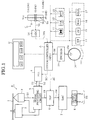
- the reproducing system of the present invention comprises a system controller A for controlling the whole of the system, a reproducing system B, a manipulating section C and a display D.
- the system controller A has a microprocessor unit (MPU) For performing a system program, and controls the reproducing system B and display D in accordance with the user's operation of the manipulating section C.
- MPU microprocessor unit
- the reproducing system B comprises a spindle motor 2 for rotating a CD 1, a pickup 3, a PLL (phase-locked loop) 4, a signal processing circuit 5, a digital signal processor (DSP) 6, a D/A converter 7, and an output circuit 8.
- a spindle motor 2 for rotating a CD 1
- a pickup 3 for rotating a CD 1
- a signal processing circuit 5 for processing signals
- DSP digital signal processor
- the PLL 4 derives a synchronizing signal from a reproduced RF signal S1 and produces a synchronizing clock S2 for reproducing which synchronizes the former synchronizing signal with the frequency and phase designated by a speed control signal SC fed from the system controller A.
- the signal processing circuit 5 produces a spindle servo control signal, focus servo control signal, and tracking servo control signal based on the synchronizing clock S2, and thereby the spindle motor 2 and the pickup 3 are controlled.
- the signal processing circuit 5 produces an audio-data S3 by separating a frame synchronizing pattern from the reproduced RF signal S1, and by processing the EFM (Eight to Fourteen Modulation) decoding, error correction and others, and feeds the audio-data to the digital signal processor 6.
- EFM Eight to Fourteen Modulation
- the digital signal processor 6 processes the audio-data S3 in accordance with an effect control signal EC to produce a converting audio-data S4 which is applied to the D/A converter 7 to convert the signal to an analogue signal. Thereby the output circuit 8 produces an analogue audio signals S5.
- a volume 9 comprising a slide resistor 9a and a slide knob 9b, and JOG dial 10, and a JOG push buttons 11 through 17.
- the slide resister 9a is connected between a source Vcc and a ground GND.
- the volume 9 outputs a divided voltage Vs in accordance with the position of the slide knob 9b.
- An A/D converter 18 converts the voltage Vs to a digital data DVs which is applied to the system controller A.
- the system controller A applies a speed control signal SC having a frequency and phase corresponding to the digital data DVs to the PLL circuit 4.
- the PLL circuit 4 produces the synchronizing clock S2 based on the speed control signal SC.
- the signal processing circuit 5 controls the spindle motor 2 and the pickup 3 in accordance with the synchronizing clock S2. Thereby the rotating speed of the CD 1 is controlled in dependency on the position of the knob 9b.
- the rotating speed of the CD 1 is set at the ordinary speed, and the speed increases toward the ground and reduces toward the Vcc.
- the changing range of the rotating speed is ⁇ 10% of the ordinary rotating speed.
- the JOG dial 10 has a recess 10a for indicating the angular position of the dial 10.
- an optical pulse encoder 19 is provided for detecting the angular speed, amount of rotation, and rotating direction of the JOG dial 10 to produce detected signals SR which is fed to the system controller A.
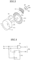
- the pulse encoder comprises a rotating circular plate 20 fixed to a rotating shaft 10b of the JOG dial 10, a fixed plate 21 opposite to the circular plate 20, and a light emitting element 22 and light receiving elements 23 and 24 opposite to the light emitting element 22, interposing the rotating plate 20 and the fixed plate 21.
- the encoder 19 has a circuit shown in Fig. 3, which comprises an EXOR gate 25 and a D-type flip-flop 26 which are connected to output terminals of the light receiving elements.
- a plurality of slits 20a circularly formed in the rotating plate 20, and a plurality of slits 21a formed in the fixed plate 21, each corresponding to an opposite slit 21a.
- the light receiving elements 23, 24 receive light beams passing through slits 20a and 21a and the circuit of Fig. 3 produces the signal SR comprising a rotating direction signal Sdr and an angular speed signal Srt as described hereinafter in detail.
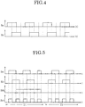
- Fig. 4 shows a timing chart showing detected signals Sa and Sb of the light receiving elements 23, 24.
- Fig. 5 shows a timing chart showing the signals Sa, Sb, Sdr and Srt.
- the signal Sa When the JOG dial 10 is rotated in the clockwise direction (+), the signal Sa generates earlier than the signal Sb.
- the signal Sb When the JOG dial 10 is rotated in the counterclockwise direction, the signal Sb generates earlier than the signal Sa. Consequently, the rotating direction signal Sdr is "O" in the clockwise direction, and the direction signal Sdr is "1" in the counterclockwise direction.
- the angular speed dependent on the speed signal Srt is detected by counting the number of the output "1" of the EXOR gate 25.
- the push button 11 is a start button
- push button 12 is a cue button for designating a start position
- the button 13 is a master tempo button.
- the button 14 is a JET effect button for generating a sound like a jet plane by operating the JOG dial 10
- the button 15 is a ZIP effect button for changing the pitch of the reproduced music in accordance with the operation of the JOG dial 10.
- the button 16 is a WAH effect button for increasing or decreasing the volume of a high frequency or low frequency range of the reproduced sound in accordance with the operation of the JOG dial 10.
- the button 17 is a HOLD effect button. When the button 17 is depressed, the reproducing conditions by the buttons 14, 15, 16 are held, and when the button is not operated, the reproducing conditions gradually return to original conditions.
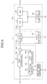
- a JET effect producing system J operated by the JET button 14 comprises a delay circuit 30 for delaying the audio data S3 from the signal processing circuit 5, a delay time coefficient circuit 31 for setting a delay time Td for the delay circuit 30, a gain control circuit 32 for reducing the audio data S3 to a half level, a gain control circuit 33 for reducing the delayed audio data S31 to a half level, and an adder 34 for adding audio data S30 and S32 from gain control circuits 32 and 33.
- the delay circuit 30 delays the audio data by the delay time Td in accordance with a coefficient fed from the delay time coefficient circuit 31 when the JET button 14 is depressed.
- the delay time coefficient circuit 31 stores delay time coefficient designated by the control signal EC from the system controller A.
- the system controller A is adapted to produce the control signal EC as the delay time coefficient data in accordance with the amount ⁇ of rotation and rotating direction of the JOG dial 10.
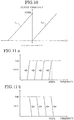
- Fig. 7 is a graph showing the relationship between the amount ⁇ of rotation and the delay time Td of the JOG dial 10.
- the delay time Td increases and decreases at every 720° rotation of the JOG dial 10 in plus and minus directions.
- a modulated audio data S24 is produced (Fig. 6), thereby producing sounds like sounds of the jet plane.
- a ZIP effect producing system Z operated by the ZIP button 15 comprises a pitch shifter 35 receiving the audio data S24 from the adder 34, and a pitch coefficient circuit 36.
- the system controller A applies a pitch coefficient data to the pitch coefficient circuit 36 by the control signal in accordance with the amount ⁇ of rotation and the rotating direction of the JOG dial 10.
- the pitch shifter 35 changes the pitch Hp of the audio data S24 based on the pitch coefficient fed from the pitch coefficient circuit 36.
- Fig. 8 shows waveforms for the changing of the pitch.
- Fig. 8a shows an original pitch of the audio data S24
- Fig. 8b shows increased pitch in the clockwise direction of the JOG dial 10
- Fig. 8c shows reduced pitch in the counterclockwise direction.
- Fig. 9 is a graph showing the relationship between the rotating direction of the JOG dial 10.
- the pitch increases 1 octave at every predetermined amount ⁇
- the pitch reduces 1.5 octave at every amount ⁇ .
- a WAH effect producing system W with the WAH button 16 comprises a low pass filter 27 which can change a cutoff frequency fCH of a high frequency range, a high pass filter 28 which can change a cutoff frequency fCL of a low frequency range of an audio data S25, and a filter coefficient circuit 29.
- the system controller A applies a filter coefficient data to the filter coefficient circuit 29 based on the amount ⁇ and the rotating direction of the JOG dial 10.
- Fig. 10 is a graph showing the relationship between the amount ⁇ of the rotation and the cutoff frequency.
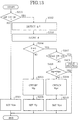
- Figs. 11a and 11b show shifting conditions of the cutoff frequencies fCH, fCL.
- the cutoff frequency is shifted toward a condition passing through the filter.
- step S100 it is determined whether JET effect button 14 is depressed.
- step S102 If yes, the amount ⁇ of the rotation of the JOG dial for a predetermined time is detected at the pulse encoder 19 at a step S102.
- the amount ⁇ of the rotation is stored in a memory (step S103).
- step S104 it is determined whether the amount ⁇ is zero. If no, and the HOLD effect button 17 is depressed (step S400), the amount ⁇ is stored in a memory (step S401), and a hold process is carried out (step S402). If the HOLD effect button is not depressed at the step 400, a delay time Td corresponding to the amount ⁇ is obtained (step S105), and a delay time coefficient Xd corresponding to the delay time Td is set (step S106).
- step S104 When the amount ⁇ is zero at the step S104, it is determined whether the HOLD effect button is depressed at a step S107. If the button is not depressed and the delay time is not zero at a step S108, a time Tdr necessary to make the delay time Td zero is calculated (S109). A delay time coefficient Xdr corresponding to the delay time Tdr is fed to the digital signal processor 6 (step S110).
- a pitch coefficient Yps corresponding to an initial pitch Hps is fed to the digital signal processor 6 (step S201).
- step S203 it is determined whether the amount ⁇ is zero. If no, a pitch Hp corresponding to the amount ⁇ is obtained (step S205). A pitch coefficient Yp corresponding to the pitch Hp is obtained and is set (step S206).
- step S207 it is determined whether the HOLD effect button is depressed at a step S207. If the button is not depressed, and the pitch Hp is not equal to the initial pitch Hps at a step S208, a return pitch Hpr necessary to make the pitch Hp the initial pitch Hps is calculated (step S209). A pitch coefficient Ypr corresponding to the pitch Hpr is fed to the digital signal processor 6 (step S210).
- step S300 it is determined whether WAH effect button 16 is depressed.
- the filter coefficient Zs for making the filters to passing through conditions Fs(f) is fed to the digital signal processor 6 (step S301).
- the amount ⁇ of the rotation of the JOG dial for a predetermined time is detected at the pulse encoder 19 at a step S302.
- the amount ⁇ of the rotation is stored in a memory (step S303).
- step S304 When the amount ⁇ is zero at the step S304, it is determined whether the HOLD effect button 17 is depressed at a step S307. If the button is not depressed and the filters are not in passing through conditions at a step S308, a return filter characteristic Fr(f) necessary to make the filter characteristic F(f) to the passing through conditions Fs(f) is calculated (step S309). A filter coefficient Zr corresponding to the filter characteristic Fr(f) is fed to the digital signal processor 6 (step S310).
- step S405 it is determined whether JET effect button 14 is depressed. When the button is not depressed, it is determined whether the ZIP effect button 15 is depressed at a step 409.
- step S406 If the button 14 is depressed, the amount ⁇ of the rotation of the JOG dial for a predetermined time is detected at the pulse encoder 19 and the amount ⁇ of the rotation is stored in a memory (step S406). A delay time Td corresponding to the amount ⁇ is obtained (step S407), and a delay time coefficient Xd corresponding to the delay time Td is set (step S408).
- step S410 When the ZIP effect button 15 is depressed, a pitch Hp corresponding to the amount ⁇ is obtained (step S410).
- a pitch coefficient Yp corresponding to the pitch Hp is obtained and set (step S411).
- a filter characteristic F(f) corresponding to the amount ⁇ is obtained (step S413), and a filter coefficient Z corresponding to the filter characteristic F(f) is set (step S414).
Abstract
Description
- The present invention relates to a system for reproducing information such as music recorded on a compact disc (CD)(hereinafter called digital disc).
- In the LP record player, the tempo, pitch and tone of the reproduced music can be variously changed by manually changing the rotating speed of the turntable of the player.
- For example, in a discotheque a disc jockey operates the turntable to produce the above described effect.
- However, in the present time, music is generally recorded on the disc such as CD.
- Since the reproducing device for the CD comprises a plurality of complicated components, it is impossible to manually change the reproducing condition unlike the LP record player.
- An object of the present invention is to provide a reproducing system which may change the music reproducing condition of the digital disc.
- According to the present invention, there is provided a system for reproducing music information recorded on a disc, comprising, a reproducing system for reproducing music recorded on a digital disc, having a spindle motor for rotating a turntable, a rotating dial to be rotated by a user, detecting means for detecting a rotating condition of the rotating dial, processing means responsive to a detected rotating condition for processing reproduced music.
- The processing means is provided for delaying the reproduced music information in accordance with the detected rotating condition, and for changing the pitch of the reproduced music information in accordance with the detected rotating condition, and for changing a frequency range of the reproduced music information in accordance with the detected rotating condition.
- The processing means is provided for returning a processed music information to an initial condition when the rotating dial is stopped.
- The rotating condition comprises an amount of rotation and rotating direction.
- The delaying operation comprises the repeating of the increasing and reducing of the delay time.
- The pitch is changed by changing the rotating speed of the spindle motor.
- The frequency range is changed by shifting a frequency range of a band pass filter.
- These and other objects and features of the present invention will become more apparent from the following detailed description with reference to the accompanying drawings.
-
- Fig. 1 is a block diagram showing a reproducing system according to an embodiment of the present invention;
- Fig.2 is a perspective view of a pulse encoder;
- Fig. 3 is a rotating condition detecting circuit;
- Fig. 4 is a timing chart showing detected signals of light receiving elements.
- Fig. 5 is a timing chart showing the signals.
- Fig. 6 is a block diagram of an effect producing system.
- Fig. 7 is a graph showing the relationship between the amount of the rotation and the delay time of the JOG dial.
- Figs. 8a to 8c are waveforms showing the changing of the pitch.
- Fig. 9 is a graph showing the relationship between rotating direction of the JOG dial.
- Fig. 10 is a graph showing the relationship between the amount of rotation and the cutoff frequency.
- Figs. 11a and 11b are graphs showing the change of band pass filter ranges;
- Figs. 12 through 15 are flowcharts showing operation of the system.
-
- Referring to Fig. 1, the reproducing system of the present invention comprises a system controller A for controlling the whole of the system, a reproducing system B, a manipulating section C and a display D.
- The system controller A has a microprocessor unit (MPU) For performing a system program, and controls the reproducing system B and display D in accordance with the user's operation of the manipulating section C.
- The reproducing system B comprises a
spindle motor 2 for rotating aCD 1, apickup 3, a PLL (phase-locked loop) 4, asignal processing circuit 5, a digital signal processor (DSP) 6, a D/A converter 7, and anoutput circuit 8. - The
PLL 4 derives a synchronizing signal from a reproduced RF signal S1 and produces a synchronizing clock S2 for reproducing which synchronizes the former synchronizing signal with the frequency and phase designated by a speed control signal SC fed from the system controller A. - The
signal processing circuit 5 produces a spindle servo control signal, focus servo control signal, and tracking servo control signal based on the synchronizing clock S2, and thereby thespindle motor 2 and thepickup 3 are controlled. - Furthermore, the
signal processing circuit 5 produces an audio-data S3 by separating a frame synchronizing pattern from the reproduced RF signal S1, and by processing the EFM (Eight to Fourteen Modulation) decoding, error correction and others, and feeds the audio-data to thedigital signal processor 6. - The
digital signal processor 6 processes the audio-data S3 in accordance with an effect control signal EC to produce a converting audio-data S4 which is applied to the D/A converter 7 to convert the signal to an analogue signal. Thereby theoutput circuit 8 produces an analogue audio signals S5. - In the operating section C, there is provided a
volume 9 comprising aslide resistor 9a and aslide knob 9b, andJOG dial 10, and aJOG push buttons 11 through 17. - The
slide resister 9a is connected between a source Vcc and a ground GND. Thevolume 9 outputs a divided voltage Vs in accordance with the position of theslide knob 9b. An A/D converter 18 converts the voltage Vs to a digital data DVs which is applied to the system controller A. - The system controller A applies a speed control signal SC having a frequency and phase corresponding to the digital data DVs to the
PLL circuit 4. ThePLL circuit 4 produces the synchronizing clock S2 based on the speed control signal SC. Thesignal processing circuit 5 controls thespindle motor 2 and thepickup 3 in accordance with the synchronizing clock S2. Thereby the rotating speed of theCD 1 is controlled in dependency on the position of theknob 9b. - When the
knob 9b is positioned at a home position shown in Fig. 1, the rotating speed of theCD 1 is set at the ordinary speed, and the speed increases toward the ground and reduces toward the Vcc. - The changing range of the rotating speed is ±10% of the ordinary rotating speed.
- The
JOG dial 10 has arecess 10a for indicating the angular position of thedial 10. - Under the
JOG dial 10, anoptical pulse encoder 19 is provided for detecting the angular speed, amount of rotation, and rotating direction of theJOG dial 10 to produce detected signals SR which is fed to the system controller A. - Referring to Fig. 2 showing the
pulse encoder 19, the pulse encoder comprises a rotatingcircular plate 20 fixed to a rotatingshaft 10b of theJOG dial 10, afixed plate 21 opposite to thecircular plate 20, and alight emitting element 22 andlight receiving elements light emitting element 22, interposing therotating plate 20 and thefixed plate 21. - The
encoder 19 has a circuit shown in Fig. 3, which comprises an EXORgate 25 and a D-type flip-flop 26 which are connected to output terminals of the light receiving elements. - There are provided a plurality of
slits 20a circularly formed in therotating plate 20, and a plurality ofslits 21a formed in thefixed plate 21, each corresponding to anopposite slit 21a. - The
light receiving elements slits - Fig. 4 shows a timing chart showing detected signals Sa and Sb of the
light receiving elements - Fig. 5 shows a timing chart showing the signals Sa, Sb, Sdr and Srt.
- When the
JOG dial 10 is rotated in the clockwise direction (+), the signal Sa generates earlier than the signal Sb. When theJOG dial 10 is rotated in the counterclockwise direction, the signal Sb generates earlier than the signal Sa. Consequently, the rotating direction signal Sdr is "O" in the clockwise direction, and the direction signal Sdr is "1" in the counterclockwise direction. The angular speed dependent on the speed signal Srt is detected by counting the number of the output "1" of the EXORgate 25. - Referring back to Fig. 1, the
push button 11 is a start button,push button 12 is a cue button for designating a start position, and thebutton 13 is a master tempo button. When thebutton 13 is pushed, if the rotating speed is changed by operating theknob 9b, the pitch of the reproduced music does not change. - The
button 14 is a JET effect button for generating a sound like a jet plane by operating theJOG dial 10, thebutton 15 is a ZIP effect button for changing the pitch of the reproduced music in accordance with the operation of theJOG dial 10. Thebutton 16 is a WAH effect button for increasing or decreasing the volume of a high frequency or low frequency range of the reproduced sound in accordance with the operation of theJOG dial 10. Thebutton 17 is a HOLD effect button. When thebutton 17 is depressed, the reproducing conditions by thebuttons - The composition for producing above described effects with the
buttons 14 through 17 is described hereinafter with reference to Figs. 6 to 11. - Referring to Fig. 6, a JET effect producing system J operated by the
JET button 14 comprises adelay circuit 30 for delaying the audio data S3 from thesignal processing circuit 5, a delay time coefficient circuit 31 for setting a delay time Td for thedelay circuit 30, a gain control circuit 32 for reducing the audio data S3 to a half level, a gain control circuit 33 for reducing the delayed audio data S31 to a half level, and an adder 34 for adding audio data S30 and S32 from gain control circuits 32 and 33. - The
delay circuit 30 delays the audio data by the delay time Td in accordance with a coefficient fed from the delay time coefficient circuit 31 when theJET button 14 is depressed. - The delay time coefficient circuit 31 stores delay time coefficient designated by the control signal EC from the system controller A.
- The system controller A is adapted to produce the control signal EC as the delay time coefficient data in accordance with the amount of rotation and rotating direction of the
JOG dial 10. - Fig. 7 is a graph showing the relationship between the amount of rotation and the delay time Td of the
JOG dial 10. The delay time Td increases and decreases at every 720° rotation of theJOG dial 10 in plus and minus directions. - By adding the delayed audio data S32 and the not delayed data S30, a modulated audio data S24 is produced (Fig. 6), thereby producing sounds like sounds of the jet plane.
- Referring to Fig. 6, a ZIP effect producing system Z operated by the
ZIP button 15 comprises a pitch shifter 35 receiving the audio data S24 from the adder 34, and apitch coefficient circuit 36. - The system controller A applies a pitch coefficient data to the
pitch coefficient circuit 36 by the control signal in accordance with the amount of rotation and the rotating direction of theJOG dial 10. - The pitch shifter 35 changes the pitch Hp of the audio data S24 based on the pitch coefficient fed from the
pitch coefficient circuit 36. - Fig. 8 shows waveforms for the changing of the pitch. Fig. 8a shows an original pitch of the audio data S24, Fig. 8b shows increased pitch in the clockwise direction of the
JOG dial 10, and Fig. 8c shows reduced pitch in the counterclockwise direction. - Fig. 9 is a graph showing the relationship between the rotating direction of the
JOG dial 10. When theJOG dial 10 is rotated in the clockwise direction (+), the pitch increases 1 octave at every predetermined amount , and when the JOG dial is rotated in the counterclockwise direction (-), the pitch reduces 1.5 octave at every amount . - Referring to Fig. 6, a WAH effect producing system W with the
WAH button 16 comprises alow pass filter 27 which can change a cutoff frequency fCH of a high frequency range, ahigh pass filter 28 which can change a cutoff frequency fCL of a low frequency range of an audio data S25, and afilter coefficient circuit 29. - The system controller A applies a filter coefficient data to the
filter coefficient circuit 29 based on the amount and the rotating direction of theJOG dial 10. - Fig. 10 is a graph showing the relationship between the amount of the rotation and the cutoff frequency.
- When the
JOG dial 10 is rotated in the clockwise direction, increases with the amount of rotation. When the JOG dial is rotated in the counterclockwise direction the cutoff frequency fCH gradually decreases with the amount . - Figs. 11a and 11b show shifting conditions of the cutoff frequencies fCH, fCL. When the rotation of the
JOG dial 10 is stopped, the cutoff frequency is shifted toward a condition passing through the filter. - The operation of the system will be described hereinafter with reference to Figs. 12 through 15.
- Referring to Fig. 12, at a step S100 it is determined whether
JET effect button 14 is depressed. When the button is not depressed, the delay coefficient Xds corresponding to the delay time Td=0 is fed to the digital signal processor 6 (step S101). - If yes, the amount Δ of the rotation of the JOG dial for a predetermined time is detected at the
pulse encoder 19 at a step S102. The amount of the rotation is stored in a memory (step S103). At a step S104, it is determined whether the amount is zero. If no, and theHOLD effect button 17 is depressed (step S400), the amount Δ is stored in a memory (step S401), and a hold process is carried out (step S402). If the HOLD effect button is not depressed at the step 400, a delay time Td corresponding to the amount is obtained (step S105), and a delay time coefficient Xd corresponding to the delay time Td is set (step S106). - When the amount is zero at the step S104, it is determined whether the HOLD effect button is depressed at a step S107. If the button is not depressed and the delay time is not zero at a step S108, a time Tdr necessary to make the delay time Td zero is calculated (S109). A delay time coefficient Xdr corresponding to the delay time Tdr is fed to the digital signal processor 6 (step S110).
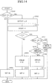
- Referring to Fig. 13, at a step S200, it is determined whether the
ZIP effect button 15 is depressed. When the button is not depressed, a pitch coefficient Yps corresponding to an initial pitch Hps is fed to the digital signal processor 6 (step S201). - If yes, the amount Δ of the rotation of the JOG dial for a predetermined time is detected at the
pulse encoder 19 at the step S202. The amount of the rotation is stored in a memory (step S203). At a step S204, it is determined whether the amount is zero. If no, a pitch Hp corresponding to the amount is obtained (step S205). A pitch coefficient Yp corresponding to the pitch Hp is obtained and is set (step S206). - When the amount is zero, it is determined whether the HOLD effect button is depressed at a step S207. If the button is not depressed, and the pitch Hp is not equal to the initial pitch Hps at a step S208, a return pitch Hpr necessary to make the pitch Hp the initial pitch Hps is calculated (step S209). A pitch coefficient Ypr corresponding to the pitch Hpr is fed to the digital signal processor 6 (step S210).
- Referring to Fig. 14, at a step S300 it is determined whether
WAH effect button 16 is depressed. When the button is not depressed, the filter coefficient Zs for making the filters to passing through conditions Fs(f) is fed to the digital signal processor 6 (step S301). - If yes, the amount Δ of the rotation of the JOG dial for a predetermined time is detected at the
pulse encoder 19 at a step S302. The amount of the rotation is stored in a memory (step S303). At a step S304, it is determined whether the amount is zero. If no, a filter characteristic F(f) corresponding to the amount is obtained (step S305), and a filter coefficient Z corresponding to the filter characteristic F(f) is set (step S306). - When the amount is zero at the step S304, it is determined whether the
HOLD effect button 17 is depressed at a step S307. If the button is not depressed and the filters are not in passing through conditions at a step S308, a return filter characteristic Fr(f) necessary to make the filter characteristic F(f) to the passing through conditions Fs(f) is calculated (step S309). A filter coefficient Zr corresponding to the filter characteristic Fr(f) is fed to the digital signal processor 6 (step S310). - Referring to Fig. 15, at a step S405, it is determined whether
JET effect button 14 is depressed. When the button is not depressed, it is determined whether theZIP effect button 15 is depressed at a step 409. - If the
button 14 is depressed, the amount Δ of the rotation of the JOG dial for a predetermined time is detected at thepulse encoder 19 and the amount of the rotation is stored in a memory (step S406). A delay time Td corresponding to the amount is obtained (step S407), and a delay time coefficient Xd corresponding to the delay time Td is set (step S408). When theZIP effect button 15 is depressed, a pitch Hp corresponding to the amount is obtained (step S410). - A pitch coefficient Yp corresponding to the pitch Hp is obtained and set (step S411).
- When the
WAH effect button 16 is depressed at a step S412, a filter characteristic F(f) corresponding to the amount is obtained (step S413), and a filter coefficient Z corresponding to the filter characteristic F(f) is set (step S414). - From the foregoing, it will be understood that it is possible to change the reproduced music to various moods only by rotating the dial.
- While the invention has been described in conjunction with preferred specific embodiment thereof, it will be understood that this description is intended to illustrate and not limit the scope of the invention, which is defined by the following claims.
Claims (9)
- A system for reproducing music information recorded on a disc, comprising:a reproducing system for reproducing music recorded on a digital disc, having a spindle motor for rotating a turntable;a rotating dial to be rotated by a user;detecting means for detecting a rotating condition of the rotating dial;processing means responsive to a detected rotating condition for processing reproduced music.
- The system according to claim 1 wherein the processing means is provided for delaying the reproduced music information in accordance with the detected rotating condition.
- The system according to claim 1 wherein the processing means is provided for changing the pitch of the reproduced music information in accordance with the detected rotating condition.
- The system according to claim 1 wherein the processing means is provided for changing a frequency range of the reproduced music information in accordance with the detected rotating condition.
- The system according to claim 1 wherein the processing means is provided for returning a processed music information to an initial condition when the rotating dial is stopped.
- The system according to claim 1 wherein the rotating condition comprises an amount of rotation and rotating direction.
- The system according to claim 2 wherein the delaying operation comprises the repeating of the increasing and reducing of the delay time.
- The system according to claim 3 wherein the pitch is changed by changing the rotating speed of the spindle motor.
- The system according to claim 4 wherein the frequency range is changed by shifting a frequency range of a band pass filter.
Applications Claiming Priority (2)
| Application Number | Priority Date | Filing Date | Title |
|---|---|---|---|
| JP10210376A JP2000030372A (en) | 1998-07-09 | 1998-07-09 | Audio reproducing device |
| JP21037698 | 1998-07-09 |
Publications (3)
| Publication Number | Publication Date |
|---|---|
| EP0973162A2 true EP0973162A2 (en) | 2000-01-19 |
| EP0973162A3 EP0973162A3 (en) | 2000-05-17 |
| EP0973162B1 EP0973162B1 (en) | 2009-09-16 |
Family
ID=16588329
Family Applications (1)
| Application Number | Title | Priority Date | Filing Date |
|---|---|---|---|
| EP99113280A Expired - Lifetime EP0973162B1 (en) | 1998-07-09 | 1999-07-08 | System for reproducing information recorded on a disc |
Country Status (4)
| Country | Link |
|---|---|
| US (2) | US6576825B2 (en) |
| EP (1) | EP0973162B1 (en) |
| JP (1) | JP2000030372A (en) |
| DE (1) | DE69941416D1 (en) |
Cited By (10)
| Publication number | Priority date | Publication date | Assignee | Title |
|---|---|---|---|---|
| EP1152393A2 (en) * | 2000-04-21 | 2001-11-07 | Samsung Electronics Co., Ltd. | Audio reproduction apparatus having audio modulation function, method used by the apparatus and remixing apparatus using the audio reproduction apparatus |
| WO2003069599A2 (en) * | 2002-02-15 | 2003-08-21 | Native Instruments Software Synthesis Gmbh | Device and method for controlling playback devices for digital information, especially music information |
| GB2388243A (en) * | 2002-05-01 | 2003-11-05 | Hanpin Electron Co Ltd | Digital audio signal player having a simulated analogue record |
| GB2388461A (en) * | 2002-05-07 | 2003-11-12 | Hanpin Electron Co Ltd | Digital audio signal player having simulated analogue record |
| GB2388462A (en) * | 2002-05-07 | 2003-11-12 | Hanpin Electron Co Ltd | Digital audio signal player having a stimulated analogue record |
| EP1391889A2 (en) * | 2002-08-23 | 2004-02-25 | Pioneer Corporation | Switch device, data-processing apparatus and playback apparatus |
| EP1391887A3 (en) * | 2002-08-23 | 2004-11-03 | Pioneer Corporation | Switch device, data-processing apparatus and playback apparatus |
| EP1391888A3 (en) * | 2002-08-23 | 2004-11-03 | Pioneer Corporation | Information processing unit, information processing method, program for the same, recording medium for recording the program therein, and reproducing unit |
| EP1519386A2 (en) * | 2003-09-29 | 2005-03-30 | Pioneer Corporation | Signal processor |
| EP1519384A2 (en) * | 2003-09-29 | 2005-03-30 | Pioneer Corporation | Signal processor |
Families Citing this family (22)
| Publication number | Priority date | Publication date | Assignee | Title |
|---|---|---|---|---|
| EP1097735A3 (en) * | 1999-10-14 | 2003-07-02 | Sony Computer Entertainment Inc. | Entertainment system, entertainment apparatus, recording medium, and program |
| NL1014526C2 (en) * | 2000-02-29 | 2001-08-30 | N2It Dev B V I O | Disc to be used in a signal processing device as well as such a device. |
| US20050275626A1 (en) * | 2000-06-21 | 2005-12-15 | Color Kinetics Incorporated | Entertainment lighting system |
| EP1423852A4 (en) * | 2001-08-07 | 2009-10-28 | Kent Justin A | System for converting turntable motion to midi data |
| US6818815B2 (en) * | 2002-05-06 | 2004-11-16 | Stanton Magnetics Inc. | Phonograph turntable with MIDI output |
| JP4075654B2 (en) * | 2003-03-25 | 2008-04-16 | ティアック株式会社 | Audio signal playback device |
| US7763843B2 (en) * | 2004-03-01 | 2010-07-27 | Stanton Magnetics, Inc. | Optical navigation system for rotary control based non-contact controller |
| EP1729615B1 (en) * | 2004-03-02 | 2019-05-08 | Signify North America Corporation | Entertainment lighting system |
| KR101403806B1 (en) * | 2005-02-02 | 2014-06-27 | 오디오브락스 인더스트리아 에 코메르씨오 데 프로두토스 엘레트로니코스 에스.에이. | Mobile communication device with music instrumental functions |
| WO2006104108A1 (en) * | 2005-03-28 | 2006-10-05 | Pioneer Corporation | Information reproducing device and method, and computer program |
| WO2006104109A1 (en) * | 2005-03-28 | 2006-10-05 | Pioneer Corporation | Information reproducing device and method, dj device, and computer program |
| KR20070010589A (en) * | 2005-07-19 | 2007-01-24 | 엘지전자 주식회사 | Mobile communication terminal with turn-table and its operating method |
| US20080013756A1 (en) * | 2006-03-28 | 2008-01-17 | Numark Industries, Llc | Media storage manager and player |
| US20080121092A1 (en) * | 2006-09-15 | 2008-05-29 | Gci Technologies Corp. | Digital media DJ mixer |
| US7928313B2 (en) * | 2006-10-26 | 2011-04-19 | Stanton Magnetics, Inc. | Variable slippage control for a disc jockey control surface |
| TW200841590A (en) * | 2007-04-14 | 2008-10-16 | Inventec Corp | Digital volume control apparatus and method thereof |
| US8110734B2 (en) * | 2008-07-15 | 2012-02-07 | Gibson Guitar Corp. | Position sensitive rotatable DJ control device |
| US8362349B2 (en) * | 2009-09-11 | 2013-01-29 | Gibson Guitar Corp. | Touch pad disc jockey controller |
| US7964782B2 (en) * | 2009-10-26 | 2011-06-21 | Hanpin Electron Co., Ltd. | Method for operating cue point on lighting ring of digital multimedia audio player |
| US8729375B1 (en) * | 2013-06-24 | 2014-05-20 | Synth Table Partners | Platter based electronic musical instrument |
| US10593313B1 (en) | 2019-02-14 | 2020-03-17 | Peter Bacigalupo | Platter based electronic musical instrument |
| KR102508508B1 (en) * | 2021-04-20 | 2023-03-09 | 울산과학기술원 | A device that plays a cover version of music based on a user's music listening history |
Citations (4)
| Publication number | Priority date | Publication date | Assignee | Title |
|---|---|---|---|---|
| US5350882A (en) * | 1991-12-04 | 1994-09-27 | Casio Computer Co., Ltd. | Automatic performance apparatus with operated rotation means for tempo control |
| US5512704A (en) * | 1992-10-12 | 1996-04-30 | Yamaha Corporation | Electronic sound signal generator achieving scratch sound effect using scratch readout from waveform memory |
| WO1997001168A1 (en) * | 1995-06-20 | 1997-01-09 | Rickli Andre | Digital processing device for audio signal |
| JPH1186446A (en) * | 1997-09-04 | 1999-03-30 | Sony Corp | Device and method for data reproduction |
Family Cites Families (10)
| Publication number | Priority date | Publication date | Assignee | Title |
|---|---|---|---|---|
| US2471534A (en) * | 1943-03-29 | 1949-05-31 | Muth William | Musical instrument |
| US2839960A (en) * | 1949-12-30 | 1958-06-24 | Baldwin Piano Co | Electronic synchronizing system for producing pitch discs and the like |
| US3197543A (en) * | 1958-08-05 | 1965-07-27 | Dimension Inc | Photoelectric organ |
| JPS62175796A (en) * | 1986-01-30 | 1987-08-01 | ヤマハ株式会社 | Automatic performer |
| JPH02203485A (en) * | 1989-01-31 | 1990-08-13 | Pioneer Electron Corp | Playing device for information recording medium |
| US5670729A (en) * | 1993-06-07 | 1997-09-23 | Virtual Music Entertainment, Inc. | Virtual music instrument with a novel input device |
| US5734731A (en) * | 1994-11-29 | 1998-03-31 | Marx; Elliot S. | Real time audio mixer |
| CN1096070C (en) * | 1995-10-13 | 2002-12-11 | 索尼公司 | Optical disk reproduction appts. and optical disk reproduction method |
| US5925843A (en) * | 1997-02-12 | 1999-07-20 | Virtual Music Entertainment, Inc. | Song identification and synchronization |
| US5969283A (en) * | 1998-06-17 | 1999-10-19 | Looney Productions, Llc | Music organizer and entertainment center |
-
1998
- 1998-07-09 JP JP10210376A patent/JP2000030372A/en active Pending
-
1999
- 1999-07-06 US US09/348,239 patent/US6576825B2/en not_active Expired - Lifetime
- 1999-07-08 DE DE69941416T patent/DE69941416D1/en not_active Expired - Lifetime
- 1999-07-08 EP EP99113280A patent/EP0973162B1/en not_active Expired - Lifetime
-
2003
- 2003-05-16 US US10/439,012 patent/US6809247B2/en not_active Expired - Lifetime
Patent Citations (4)
| Publication number | Priority date | Publication date | Assignee | Title |
|---|---|---|---|---|
| US5350882A (en) * | 1991-12-04 | 1994-09-27 | Casio Computer Co., Ltd. | Automatic performance apparatus with operated rotation means for tempo control |
| US5512704A (en) * | 1992-10-12 | 1996-04-30 | Yamaha Corporation | Electronic sound signal generator achieving scratch sound effect using scratch readout from waveform memory |
| WO1997001168A1 (en) * | 1995-06-20 | 1997-01-09 | Rickli Andre | Digital processing device for audio signal |
| JPH1186446A (en) * | 1997-09-04 | 1999-03-30 | Sony Corp | Device and method for data reproduction |
Non-Patent Citations (1)
| Title |
|---|
| PATENT ABSTRACTS OF JAPAN vol. 1999, no. 08, 30 June 1999 (1999-06-30) & JP 11 086446 A (SONY CORP), 30 March 1999 (1999-03-30) * |
Cited By (23)
| Publication number | Priority date | Publication date | Assignee | Title |
|---|---|---|---|---|
| EP1152393A2 (en) * | 2000-04-21 | 2001-11-07 | Samsung Electronics Co., Ltd. | Audio reproduction apparatus having audio modulation function, method used by the apparatus and remixing apparatus using the audio reproduction apparatus |
| EP1152393B1 (en) * | 2000-04-21 | 2011-06-15 | Samsung Electronics Co., Ltd. | Audio reproduction apparatus having audio modulation function, method used by the apparatus and remixing apparatus using the audio reproduction apparatus |
| WO2003069599A2 (en) * | 2002-02-15 | 2003-08-21 | Native Instruments Software Synthesis Gmbh | Device and method for controlling playback devices for digital information, especially music information |
| WO2003069599A3 (en) * | 2002-02-15 | 2004-08-26 | Native Instruments Software Synthesis Gmbh | Device and method for controlling playback devices for digital information, especially music information |
| GB2388243A (en) * | 2002-05-01 | 2003-11-05 | Hanpin Electron Co Ltd | Digital audio signal player having a simulated analogue record |
| GB2388243B (en) * | 2002-05-01 | 2004-09-08 | Hanpin Electron Co Ltd | Digital audio signal player having a simulated analogue record |
| GB2388461A (en) * | 2002-05-07 | 2003-11-12 | Hanpin Electron Co Ltd | Digital audio signal player having simulated analogue record |
| GB2388462A (en) * | 2002-05-07 | 2003-11-12 | Hanpin Electron Co Ltd | Digital audio signal player having a stimulated analogue record |
| GB2388461B (en) * | 2002-05-07 | 2004-06-23 | Hanpin Electron Co Ltd | Digital audio signal player having a simulated analogue record |
| GB2388462B (en) * | 2002-05-07 | 2004-06-23 | Hanpin Electron Co Ltd | Digital audio signal player having a simulated analogue record |
| EP1391889A3 (en) * | 2002-08-23 | 2004-11-03 | Pioneer Corporation | Switch device, data-processing apparatus and playback apparatus |
| EP1391887A3 (en) * | 2002-08-23 | 2004-11-03 | Pioneer Corporation | Switch device, data-processing apparatus and playback apparatus |
| EP1391888A3 (en) * | 2002-08-23 | 2004-11-03 | Pioneer Corporation | Information processing unit, information processing method, program for the same, recording medium for recording the program therein, and reproducing unit |
| US7269103B2 (en) | 2002-08-23 | 2007-09-11 | Pioneer Corporation | Switch device, data-processing apparatus and playback apparatus |
| US7294796B2 (en) | 2002-08-23 | 2007-11-13 | Pioneer Corporation | Switch device, data-processing apparatus and playback apparatus |
| US7787342B2 (en) | 2002-08-23 | 2010-08-31 | Pioneer Corporation | Information processing unit, information processing method, program for the same, recording medium for recording the program therein, and reproducing unit |
| EP1391889A2 (en) * | 2002-08-23 | 2004-02-25 | Pioneer Corporation | Switch device, data-processing apparatus and playback apparatus |
| EP1519386A2 (en) * | 2003-09-29 | 2005-03-30 | Pioneer Corporation | Signal processor |
| EP1519384A2 (en) * | 2003-09-29 | 2005-03-30 | Pioneer Corporation | Signal processor |
| EP1519386A3 (en) * | 2003-09-29 | 2005-04-06 | Pioneer Corporation | Signal processor |
| EP1519384A3 (en) * | 2003-09-29 | 2005-04-06 | Pioneer Corporation | Signal processor |
| US7742686B2 (en) | 2003-09-29 | 2010-06-22 | Pioneer Corporation | Signal processor |
| US7751684B2 (en) | 2003-09-29 | 2010-07-06 | Pioneer Corporation | Signal processor |
Also Published As
| Publication number | Publication date |
|---|---|
| US20030193846A1 (en) | 2003-10-16 |
| EP0973162B1 (en) | 2009-09-16 |
| JP2000030372A (en) | 2000-01-28 |
| DE69941416D1 (en) | 2009-10-29 |
| EP0973162A3 (en) | 2000-05-17 |
| US6809247B2 (en) | 2004-10-26 |
| US6576825B2 (en) | 2003-06-10 |
| US20010011497A1 (en) | 2001-08-09 |
Similar Documents
| Publication | Publication Date | Title |
|---|---|---|
| EP0973162B1 (en) | System for reproducing information recorded on a disc | |
| US7227963B1 (en) | Audio signal processing apparatus | |
| CA1232681A (en) | Optical disk record player | |
| US5313011A (en) | Apparatus for carrying out automatic play in synchronism with playback of data recorded on recording medium | |
| JPH08195068A (en) | Audio signal mixer | |
| US5159141A (en) | Apparatus for controlling reproduction states of audio signals recorded in recording medium and generation states of musical sound signals | |
| JP2629173B2 (en) | Disk playback device | |
| US7495166B2 (en) | Sound processing apparatus, sound processing method, sound processing program and recording medium which records sound processing program | |
| US5559607A (en) | Apparatus for controlling reproduction speed for laser disc player | |
| JP3272775B2 (en) | Electronic guitar | |
| JPH04114365A (en) | Disk reproducing device | |
| US5400410A (en) | Signal separator | |
| JP3911752B2 (en) | Audio playback device | |
| JP3739057B2 (en) | Sound effect generator | |
| EP3734591B1 (en) | Musical sound effect adding device and musical sound effect adding program | |
| JP2629739B2 (en) | Audio signal attenuator | |
| JP3090075B2 (en) | Variable speed playback device | |
| EP3734592A1 (en) | Musical sound effect adding device and musical sound effect adding program | |
| JPS63255873A (en) | Method for setting sound recording level | |
| JPH045693A (en) | Electronic musical instrument | |
| JPS637973Y2 (en) | ||
| JP2629231B2 (en) | Audio signal attenuator | |
| JPH02232870A (en) | Disk player | |
| JPH05258407A (en) | Recording medium reproduction speed detecting device and recording medium reproduction speed controlling device | |
| JPS58220223A (en) | Digital zero cross detecting circuit |
Legal Events
| Date | Code | Title | Description |
|---|---|---|---|
| PUAI | Public reference made under article 153(3) epc to a published international application that has entered the european phase |
Free format text: ORIGINAL CODE: 0009012 |
|
| AK | Designated contracting states |
Kind code of ref document: A2 Designated state(s): DE ES FR GB IT |
|
| AX | Request for extension of the european patent |
Free format text: AL;LT;LV;MK;RO;SI |
|
| PUAL | Search report despatched |
Free format text: ORIGINAL CODE: 0009013 |
|
| AK | Designated contracting states |
Kind code of ref document: A3 Designated state(s): AT BE CH CY DE DK ES FI FR GB GR IE IT LI LU MC NL PT SE |
|
| AX | Request for extension of the european patent |
Free format text: AL;LT;LV;MK;RO;SI |
|
| RIC1 | Information provided on ipc code assigned before grant |
Free format text: 7G 11B 19/02 A, 7G 11B 19/247 B, 7G 10H 1/00 B |
|
| 17P | Request for examination filed |
Effective date: 20000515 |
|
| AKX | Designation fees paid |
Free format text: DE ES FR GB IT |
|
| GRAP | Despatch of communication of intention to grant a patent |
Free format text: ORIGINAL CODE: EPIDOSNIGR1 |
|
| GRAS | Grant fee paid |
Free format text: ORIGINAL CODE: EPIDOSNIGR3 |
|
| GRAA | (expected) grant |
Free format text: ORIGINAL CODE: 0009210 |
|
| AK | Designated contracting states |
Kind code of ref document: B1 Designated state(s): DE ES FR GB IT |
|
| REG | Reference to a national code |
Ref country code: GB Ref legal event code: FG4D |
|
| REF | Corresponds to: |
Ref document number: 69941416 Country of ref document: DE Date of ref document: 20091029 Kind code of ref document: P |
|
| PG25 | Lapsed in a contracting state [announced via postgrant information from national office to epo] |
Ref country code: ES Free format text: LAPSE BECAUSE OF FAILURE TO SUBMIT A TRANSLATION OF THE DESCRIPTION OR TO PAY THE FEE WITHIN THE PRESCRIBED TIME-LIMIT Effective date: 20091227 |
|
| REG | Reference to a national code |
Ref country code: GB Ref legal event code: 746 Effective date: 20100630 |
|
| PLBE | No opposition filed within time limit |
Free format text: ORIGINAL CODE: 0009261 |
|
| STAA | Information on the status of an ep patent application or granted ep patent |
Free format text: STATUS: NO OPPOSITION FILED WITHIN TIME LIMIT |
|
| 26N | No opposition filed |
Effective date: 20100617 |
|
| PG25 | Lapsed in a contracting state [announced via postgrant information from national office to epo] |
Ref country code: IT Free format text: LAPSE BECAUSE OF FAILURE TO SUBMIT A TRANSLATION OF THE DESCRIPTION OR TO PAY THE FEE WITHIN THE PRESCRIBED TIME-LIMIT Effective date: 20090916 |
|
| REG | Reference to a national code |
Ref country code: DE Ref legal event code: R082 Ref document number: 69941416 Country of ref document: DE Representative=s name: MEISSNER, BOLTE & PARTNER GBR, DE |
|
| REG | Reference to a national code |
Ref country code: FR Ref legal event code: CD Owner name: PIONEER CORPORATION, JP Effective date: 20150112 Ref country code: FR Ref legal event code: CA Effective date: 20150112 |
|
| REG | Reference to a national code |
Ref country code: DE Ref legal event code: R082 Ref document number: 69941416 Country of ref document: DE Representative=s name: MEISSNER BOLTE PATENTANWAELTE RECHTSANWAELTE P, DE Effective date: 20150113 Ref country code: DE Ref legal event code: R082 Ref document number: 69941416 Country of ref document: DE Representative=s name: MEISSNER, BOLTE & PARTNER GBR, DE Effective date: 20150113 Ref country code: DE Ref legal event code: R081 Ref document number: 69941416 Country of ref document: DE Owner name: PIONEER DJ CORPORATION, KAWASAKI-SHI, JP Free format text: FORMER OWNER: PIONEER ELECTRONIC CORP., TOKIO/TOKYO, JP Effective date: 20150113 Ref country code: DE Ref legal event code: R081 Ref document number: 69941416 Country of ref document: DE Owner name: PIONEER CORPORATION, JP Free format text: FORMER OWNER: PIONEER ELECTRONIC CORP., TOKIO/TOKYO, JP Effective date: 20150113 |
|
| REG | Reference to a national code |
Ref country code: GB Ref legal event code: 732E Free format text: REGISTERED BETWEEN 20150409 AND 20150415 |
|
| REG | Reference to a national code |
Ref country code: FR Ref legal event code: PLFP Year of fee payment: 17 |
|
| REG | Reference to a national code |
Ref country code: FR Ref legal event code: TP Owner name: PIONEER DJ CORPORATION, JP Effective date: 20150623 |
|
| REG | Reference to a national code |
Ref country code: DE Ref legal event code: R082 Ref document number: 69941416 Country of ref document: DE Representative=s name: MEISSNER BOLTE PATENTANWAELTE RECHTSANWAELTE P, DE Ref country code: DE Ref legal event code: R082 Ref document number: 69941416 Country of ref document: DE Representative=s name: MEISSNER, BOLTE & PARTNER GBR, DE Ref country code: DE Ref legal event code: R081 Ref document number: 69941416 Country of ref document: DE Owner name: PIONEER DJ CORPORATION, KAWASAKI-SHI, JP Free format text: FORMER OWNER: PIONEER CORPORATION, KANAGAWA, JP |
|
| REG | Reference to a national code |
Ref country code: GB Ref legal event code: 732E Free format text: REGISTERED BETWEEN 20160114 AND 20160120 |
|
| REG | Reference to a national code |
Ref country code: FR Ref legal event code: TP Owner name: PIONEER DJ CORPORATION, JP Effective date: 20160316 Ref country code: FR Ref legal event code: CD Owner name: PIONEER DJ CORPORATION, JP Effective date: 20160316 |
|
| REG | Reference to a national code |
Ref country code: FR Ref legal event code: PLFP Year of fee payment: 18 |
|
| REG | Reference to a national code |
Ref country code: FR Ref legal event code: PLFP Year of fee payment: 19 |
|
| PGFP | Annual fee paid to national office [announced via postgrant information from national office to epo] |
Ref country code: FR Payment date: 20170613 Year of fee payment: 19 |
|
| PGFP | Annual fee paid to national office [announced via postgrant information from national office to epo] |
Ref country code: GB Payment date: 20170705 Year of fee payment: 19 |
|
| PGFP | Annual fee paid to national office [announced via postgrant information from national office to epo] |
Ref country code: DE Payment date: 20180626 Year of fee payment: 20 |
|
| GBPC | Gb: european patent ceased through non-payment of renewal fee |
Effective date: 20180708 |
|
| PG25 | Lapsed in a contracting state [announced via postgrant information from national office to epo] |
Ref country code: GB Free format text: LAPSE BECAUSE OF NON-PAYMENT OF DUE FEES Effective date: 20180708 Ref country code: FR Free format text: LAPSE BECAUSE OF NON-PAYMENT OF DUE FEES Effective date: 20180731 |
|
| REG | Reference to a national code |
Ref country code: DE Ref legal event code: R071 Ref document number: 69941416 Country of ref document: DE |