Field of the Invention
-
This invention relates to the use of one or more robotic arms in an automated
analytical instrument to transport test tubes and other containers or objects between various
locations within the instrument and optionally to and from a transport line system in an
automated laboratory transport system.
Cross-Reference to Related Applications
-
This application is related to the following U.S. patent applications, having the
indicated titles, commonly assigned to the Bayer Corporation of Tarrytown, New York and
incorporated by reference herein:
- (a) design patent applications for Gripper Finger, Ser. No. , filed concurrently
herewith (Attorney Docket No. 8698-2053); Sample Tube Rack, Ser. No. , filed (Internal
Docket No. MST-1988.1); and Sample Tube Rack, Ser. No. , filed June 15, 1998 (Internal
Docket No. MST-2302);
- (b) utility patent applications for Sample Tube Rack, Ser. No. , filed
(Internal Docket No. MST-1988.1); Sample Tube Rack, Ser. No. , filed June 15, 1998
(Internal Docket No. MST-2302); Reagent Package, Ser. No. 08/985,759, filed December 5,
1997 (Internal Docket No. MST-1968.1); Diluent Package, Ser. No. 29/088,045, filed May 14,
1998 (Internal Docket No. MST-2305); Automatic Handler for Feeding Containers Into and Out
of An Analytical Instrument ("Sample Handler"), Ser. No. , filed concurrently herewith
(Attorney Docket No. 8698-2050); Automatic Decapper, Ser. No. , filed concurrently herewith
(Attorney Docket No. 8698-2049); and Cup Handling Subsystem for an Automated Clinical
Chemistry Analyzer System, Ser. No. filed (Attorney Docket No. 8698-2039).
-
Background of the Invention
-
Robotics have been incorporated into analytical instruments in various ways. The
most common use of robotics in these instruments has been to transport a pipette to aspirate
liquid from a test tube. Another use of robotics has been to transport a test tube rack within an
automated testing system, as described in U.S. Patent No. 5,260,872.
-
Robotics have also been used to transport test tubes within an instrument. For
example, U.S. Patent No. 4,835,711 to Hutchins et al. illustrates a robotic arm transporting a test
tube to various work stations which are placed in a circle around the robotic arm. The robotic
arm is mounted to a fixed position on the workstation and rotates about an axis perpendicular to
the surface of the workstation. As illustrated, the test tube appears to be gripped within gripper
fingers, the ends of which are curved in the shape of the test tube. No provision is made to
transport containers other than test tubes.
-
Another robotic arm for transporting a test tube is shown in International
Publication No. WO 90/03834. This robotic arm rotates and may lift or lower the test tube but
the robotic arm is not translatable along any axis. The gripper fingers are only shown and
described as gripping a test tube.
-
U.S. Patent No. 4,835,707 to Amano et al. describes a robotic arm that is mounted
to the central portion of the workstation and articulates in the x, y, and z axes and rotates in the
theta direction. The robot may grasp a sample tube or one of various circular nozzles on the
workstation with a chuck.
-
International Publication No. WO 93/15407 describes the movement of a test tube
with a robotic arm with a "hand" to carry the test tube between a mosaic of tesserae of devices
and subsidiary devices. The robotic arm may move along a rail in a first axis and a horizontal
arm is translatable along second and third axes (vertically and horizontally) and is pivotable
about an axis of rotation. This application also teaches that more than one similar apparatuses
may be adjoined by and cooperate with another by extending the rails supporting the robots to
extend over the adjoining apparatus.
-
While extending a rail from one apparatus to another similar apparatus is one
approach to moving a robotic arm between instruments, this approach is not ideal for
transporting objects between more than a few instruments as the rail along which the robotic arm
must move becomes significantly long. A better alternative is to use a lab automation transport
line to transport test tubes between instruments positioned along the side of the transport line.
One such transport line is described in U.S. Patent No. 5,623,415 to O'Bryan and assigned to
SmithKline Beecham Corporation. In the O'Bryan patent, a generic pick-and-place engine, with
a robotic arm and grip, is referenced as the means for transferring test tubes between the
transport line and the instruments. Alternatively, a pipetting engine may pipette specimens of
samples from the test tubes in the transport line for use by the instrument.
Summary of the Invention
-
It is an object of this invention to provide one or more robotic arms having
gripper fingers that may grip and transport individual containers of various types, including
various types and sizes of test tubes (including tubes to hold samples, calibrators and controls),
customized reagent and diluent packages, dilution cups and pretreatment incubator covers, from
a first, source location to a second, destination location. For simplicity, unless otherwise
specified, the term "container" as used in this application shall include, but not be limited to,
objects and each of the foregoing specifically enumerated examples of containers. The robotic
arm(s) of the present invention may be advantageously used in a variety of applications, such as
a means of transport between modules of a modular automated analytical instrument or between
an analytical instrument and a sample transport line.
-
It is a further object of this invention to provide an analytical instrument that may
have at least two robotic arms wherein one of the robotic arms is capable of handling the full
workload of the instrument if the other robotic arm is disabled.
-
It is a further object of this invention to provide a robotic arm that has a first
attachment for transporting various types of containers from a first location to a second location
in an automated analytical instrument and an interchangeable second attachment for transporting
the containers from the instrument to a lab automation system or vice versa.
-
It is a further object of this invention to provide a service tool, which is used to
remove robotic arms easily for replacement and service.
-
It is a further object of this invention to provide a self-teaching process for the
robotic arms to account for slight variations in the locations of areas on the instrument which are
addressable.
-
To achieve these objectives, a robotic arm for an analytical instrument has two
translational degrees of freedom, a first along the x-axis and a second along the z-axis, and one
rotational degree of freedom in a theta direction about the z-axis. The robotic arm comprises a
platform that may move along a rail running above the rear of the instrument and defining the x-axis,
a lead screw assembly coupled to the platform and defining the z-axis, a gripper arm
coupled to the lead screw assembly to move along the lead screw, grippers mounted to the outer
end of the gripper arm, and two gripper fingers. The gripper arm, grippers, and gripper fingers
may collectively be referred to as the gripper assembly. The x, z and theta movements are
powered by respective servo motors and the grippers are coupled to electronics mounted above
the grippers, including an inertia switch and an encoder. An analytical instrument may have at
least two of these robotic arms to increase the throughput of the instrument and to provide
redundancy in the event that one of the robotic arms fail.
-
In a first aspect of the present invention, each of the gripper fingers on the robotic
arm have upper and lower projections separated by a groove. The grooves allows the fingers to
grip and transport various types of containers that have flanges that fit within the grooves,
including specialized containers, such as reagent and diluent packages and dilution cups
designed for use with-the instrument, or other containers with flanges. In addition to capturing
the flange, the groove self-aligns a misaligned container as the fingers close around the flange by
pushing down on the top of the flange with the bottom of the upper projections and pushing up
on the bottom of the flange with the top of the lower projections. The fingers may use the upper
and lower projections to grip and transport other containers with cylindrical exterior gripping
surfaces, including individual test tubes where the fingers are sufficiently long.
-
In another aspect of the present invention, the distance to which the fingers
separate from one another is limited to a distance smaller than the opening of the grippers. This
is preferably accomplished with a rod mounted to one of the fingers, passing through an aperture
on the other finger, and ending in a stop, which prevents the fingers from separating more than a
desired distance.
-
In another aspect of the present invention, the robotic arm may have an absolute
encoder either coupled to the gripper assembly, the platform, or preferably a separate absolute
encoder for each of the gripper assembly the platform to determine whether the robotic arm is in
a position where it may be safely homed without hitting an obstruction.
-
In another aspect of the present invention, because it is desirable in certain
situations for the reach of the robotic arm not to extend to some areas of the chassis, the robotic
arm may instead reach these locations by inserting a container into or removing a container from
a shuttle on the chassis that moves along the y-axis and provides access to at least some of those
locations to which the robotic arm cannot reach. The shuttle is preferably a rack that may hold
multiple containers.
-
In another aspect of the present invention, the analytical instrument is designed to
be used in conjunction with a laboratory automation system. The instrument has side posts and a
gap between the side posts that is large enough to allow the gripper arm to pivot outside of the
instrument with a sufficient reach for the fingers to transport test tubes between the transport line
of the laboratory automation system and the instrument.
-
In another aspect of the invention, the platform of the robotic arm is coupled to
the rail on the instrument with a bearing plate to simplify the removal of the robotic arm for
service or replacement. The service or replacement may be further simplified, in yet another
aspect of the invention, with a service tool that is mounted to one side of the instrument. The
robotic arm may be transferred from the rail on the instrument to a rail extension on the service
tool for easier access.
Brief Description of the Drawings
-
The inventions and modifications thereof will become better evident from the
detailed description below in conjunction with the following figures, in which like reference
characters refer to like elements, and in which:
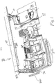
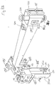
- Fig. 1 is an isometric view of a first embodiment of a single robotic arm of the
present invention mounted to a beam, which is positioned over various modules of an analytical
instrument, and adjacent to a transport system of a laboratory automation system;
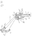
- Fig. 2 is an isometric view of the robotic arm of Fig. 1 mounted to the beam with
the gripper arm fully lowered;
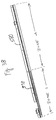
- Fig. 3A is an isometric view of the beam including the rail and rack along which
the robotic arm moves in the x-direction;
- Fig. 3B is a perspective view of the zonal homing bar;
- Fig. 4A is an isometric view of the top of the saddle platform mounted to the rail
and coupled to the rack (the remainder of the beam and robotic arm are not shown);
- Fig. 4B is an exploded view of the top of the saddle platform separated from the
bearing plate;
- Fig. 4C is a further exploded view of the saddle platform without the bearing
plate;
- Fig. 5A is an isometric view of the bottom of the saddle platform and the theta-motor
and z-motor assemblies (the lead screw assembly is not shown);
- Fig. 5B and 5C are exploded views of the bottom of the saddle platform shown in
Fig. 5A;
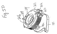
- Fig. 5D is a top view of the theta homing plate mounted above the theta encoder
ring;
- Fig. 5E is a cross-sectional view along line 5-5 of Fig. 2 of the kit motor housing
surrounding the upper portion of the robotic arm including the z-motor;
- Fig. 5F is a side view of an incremental encoder that may be used to track the
position of the gripper arm along the z-axis;
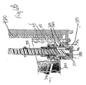
- Fig. 6A is a perspective view of the robotic arm with the arm in a fully lowered
position along the z-axis;
- Fig. 6B is a cross-sectional view of the portion of the robotic arm shown in Fig.
6A along line 6-6;
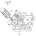
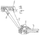
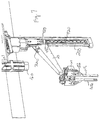
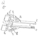
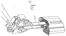
- Fig. 7 is a perspective view of robotic arm with the gripper arm raised along the
lead screw assembly;
- Fig. 8A is an isometric view of a gripper arm from the left side of the gripper arm;
- Fig. 8B is an isometric view of the gripper arm from the right side of the gripper
arm;
- Fig. 8C is a rear view of the gripper fingers;
- Fig. 8D is a top view of the encoder plate mounted to the fingers;
- Fig. 9 is a perspective view of the robotic arm having a gripper arm according to a
second embodiment of the invention;
- Fig. 10 is a rear view of a gripper arm shown in Fig. 8;
- Fig. 11A is a perspective view of the robotic arm gripping a test tube;
- Fig. 11B is a perspective view of an incubator cover that may be gripped by the
robotic arm;
- Fig. 11C is a perspective view of a predilution cup, which may be gripped by the
robotic arm;
- Fig. 12 is an isometric view of a reagent package having a gripping block from
which fingers on robotic arm may grip the package;
- Fig. 13 is an isometric view of fingers gripping the reagent package of Fig. 12;
- Fig. 14 is a plan view of a representation of a positional ambiguity presented by a
robotic arm that may move in x and theta directions;
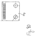
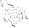
- Fig. 15 is a top view of theta homing plate;
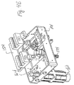
- Fig. 16 is a front view of two robotic arms mounted to a beam;
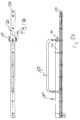
- Fig. 17A is a front view of the service tool for the robotic arm; and
- Fig. 17B is a bottom view of the service tool of Fig. 17A.
-
Detailed Description of the Preferred Embodiment
-
Referring to Fig. 1, an analytical instrument 10 has a sample handler module 20
for feeding test tubes of various sizes and other containers to the instrument 10, and one or more
additional modules, at least some of which may be optional. The modules prepare a supplied test
tube for analysis, if necessary, and then perform one or more analyses on the test tube. Sample
handler 20 may include an automatic decapper, as described in the referenced Automatic
Decapper application, (not shown in Fig. 1 but which may be located in location 30) for
decapping capped test tubes and a reagent activator 36 for preparing reagent packages for use by
analytical modules. There may also be a module 31 for processing the tubes before analysis,
including a predilution apparatus for adding reagents and diluents to and incubating samples (as
described in the referenced "Cup Handling Subsystem" application, and an ion selective
electrode apparatus for measuring electrolytes in body fluid. There may also be one or more
analytical modules including a clinical analysis module 33, and an immunoassay module
represented by box 34. Containers that are transported within the instrument include various
types and sizes of capped or uncapped test tubes (including tubes, with or without insert cups, to
hold samples, calibrators, and controls), customized reagent and diluent packages, dilution cups
and pretreatment incubator covers (which cover the dilution cups in the heated dilution module
during the dilution process to confine the heat).
-
A beam 40 runs above the rear of the instrument 10. (Fig. 2) The length of beam
40 will vary depending on the length of the instrument 10, which may have a varying number of
modules. A robotic arm 100, which reaches over at least a rear area of instrument 10, and which
for safety reasons is preferably not accessible to the operator, is mounted to beam 40 and is
designed for picking up and transporting the containers. Robotic arm 100 comprises several
sections, including saddle platform 101, a vertically mounted lead screw assembly 102, a gripper
arm 103 coupled to lead screw assembly 102 on one end, and a gripper actuator 104 and gripper
fingers 105, including right finger 105R and left finger 105L, mounted to the other end of gripper
arm 103 for gripping the containers.
-
Robotic arm 100 has four degrees of freedom of movement above the sample
handler 20 and modules 30-34. First, the entire robotic arm 100 may move linearly in the x-direction
defined by beam 40 along saddle platform 101. Second, gripper arm 103 may also
move linearly up and down along the z-axis defined by lead screw assembly 102. Third, lead
screw assembly 102 is rotatable, thereby causing an angular (or theta) motion of gripper arm 103
about the z-axis in a theta direction. Fourth, gripper fingers 105 open and close linearly.
-
As shown in Fig. 3A, beam 40 comprises a precision plate 110, a beam box
assembly 111 mounted to the bottom rear of precision plate 110, a rack 112 mounted to the
bottom of precision plate 110 in front of beam box assembly 111, and a linear sliding rail 113
mounted to the bottom of precision plate 110 in front of rack 112. The length of beam 40, rack
112 and rail 113 will depend on the number and size of analytical modules in instrument 10.
-
Rotatable hard stops 120-123 are mounted across the top front of beam 40, two
near each end of beam 40. Hard stops 120-123 may be rotated upward and into respective
exposed recesses 130-133 on the front of beam 40 or may be turned down as shown. Also
mounted to the front of beam 40 across the top left side of beam 40 is a zonal homing bar (Figs.
1 and 3B). The function of hard stops 120-123 and zonal homing bar 580 will be discussed in
more detail below.
-
Robotic arm 100 is mounted to beam 40 with one or more bearing blocks. In the
preferred embodiment, the bearing blocks may comprise two linear ball retained bearing blocks
150, 151 coupled the top of saddle platform 101 that are mounted to and linked together by
bearing plate 154. (Figs. 4A and 4B) Bearing blocks 150, 151 may be purchased premounted by
the manufacturer to rail 113. While rail 113 may vary in length, preferred rails with premounted
bearing blocks are manufactured by IKO of Japan as the LWE series. (For example, for a rail
that is 1660 mm long, the preferred rail with bearing blocks is IKO model number
LWESC20C2R1660H.) A tongue 152 on each of bearing blocks 150, 151 slides along tracks
153a, 153b on the front and back of rail 113. Alternatively, roller bearings may be used to
couple robotic arm 100 to rail 113, instead of ball bearings. In determining the number and type
of bearing blocks to use, one must take into account that the bearing block or blocks must carry
the maximum load of robotic arm 100 loaded with the heaviest container it may carry, and must
be able to accelerate and travel at the desired speeds smoothly while keeping noise to a
minimum, minimizing torque about each of the x, y and z axes to maintain robotic arm 100
relative to the predefined locations on instrument 10 which it must reach, and not wearing
excessively. The maximum torque of each of bearing blocks 150, 151 may be determined from
handbooks obtainable from the bearing block manufacturer. Saddle platform 101 is removably
mounted to bearing plate 154 to easily remove robotic arm 100 at saddle 101 for service.
-
Referring to Figs. 4A and 5B, robotic arm 100 is driven in a linear motion along
the x-axis by an "x-motor" 160 mounted beneath saddle platform 101. X-motor 160 is
preferably a brushless closed-loop servo motor coupled to a gear box and has a built-in
incremental encoder to track the position of robotic arm 100 along rail 113. X-motor 160 may be
the motor manufactured by Parker/Compumotor of Rhonert Park, CA as Model No. CM160XE-00438
that has a built-in optical encoder to track the position of robotic arm 100 and has a gear
box with a gear ratio between the motor and gear of 5.5:1. The particular motor 160 is selected
to achieve the desired speeds and accelerations, to prevent oscillations of the robotic arm and to
provide smooth transitions when accelerating and decelerating to minimize jerk, which may
cause samples in open test tubes to spill and may cause excessive noise. A drive shaft 161 on x-motor
160 passes through saddle platform 101 and attaches to a pinion 164 above saddle
platform 101. Pinion 164 engages against rack 112, thereby driving robotic arm 100 in the x-direction.
X-motor 160 is mounted to an adjustable mounting plate 166 (Fig. 5C) and mounting
plate 166 is mounted to saddle platform 101. Slots 167 on mounting plate 166 allow for the
minor adjustment of x-motor toward or away from rack 112 to accommodate some imprecision
in the mounting of rack 112 along beam 40. Pinion 164 is held in place with a split hub clamp
(not shown).
-
A "theta motor" 170 to rotate gripper arm 103 in a theta direction is mounted to a
mounting plate 176 and mounting plate 176 is then mounted to the top of saddle platform 101.
(Fig. 4C). Slots 177 in mounting plate 176 provide for the minor adjustment in the positioning
of theta motor 170. A drive shaft 172 of theta motor 170 passes through a hole 179 in the bottom
of saddle platform 101 and a pulley 174 is attached at the end of drive shaft 172. Pulley 174 is
indirectly coupled to a planetary gear 180 mounted underneath saddle platform 101 with a
synchronous timing drive belt 181 having teeth. (Figs. 5A - 5C) Drive belt 181 is tightened in
place with idler point 182 attached to a mounting pin 183 on the bottom of saddle platform 101
that increases the length of drive belt 181 which contacts pinion 174 and planetary gear 180 and
provides for the proper tensioning of drive belt 181. Planetary gear 180 is held in place with a
thrust plate 184. A preferred theta motor 170 may be identical to x-motor 160. The drive ratio
between planetary gear 180 and pulley 174 for theta motor 170 should preferably be 10:1.
-
The various components mounted between saddle platform 101 and thrust plate
184 are shown in an exploded view in Fig. 5C. An aperture 190 in saddle platform 101 extends
downward from saddle platform 101 through the bottom of a circular projection 191 formed at
the bottom of saddle platform 101. An absolute two-bit encoder is provided to create zones
along theta over which it is safe to home as described below. The absolute encoder comprises an
encoder ring 211 and two optical vane- type sensors 212, 213. Sensor 213 is mounted farther
from the center of encoder ring 211 than sensor 212. The operation of encoder 210 will be
described below. Homing in the theta direction is achieved by a homing plate 214 mounted to
encoder ring 211, and planetary gear 180 and homing stop pin 217 extending from saddle
platform 101 (Fig. 5D). Homing stop pin 217 on the bottom of saddle platform 101 is positioned
within an arcuate slot 216 on homing plate 214. Kit motor housing 220 (Figs. 5A and 5B) is
mounted to the bottom of planetary gear 180, and the top of lead screw bracket 190 is mounted
to the outside of housing 220 at point 222 on connector 221. (Fig. 5A)
-
The activation of theta-motor 170 causes the rotation of planetary gear 180 and
the theta rotation of robotic arm 100. The theta range of movement is limited to less than 360
degrees to avoid hitting a possible back wall on instrument 10. In the illustrated embodiment,
the theta range of movement is limited by homing stop pin 217 inserted in slot 216 which
extends around only a portion of homing plate 214.
-
A "z-motor" 240 raises and lowers gripper arm 103 in the z-direction. Z-motor
240 is preferably a brushless closed-loop servo motor assembled below saddle platform 101 from
a kit motor. The kit motor comprises a rotor 241 that is press fit onto a lead screw 250 and a
stator 242 that is press fit to the inside of kit motor housing 220. (Fig. 5E) One suitable kit
motor for z-motor 240 is manufactured by MFM Model No. K032. An incremental encoder is
also provided to track the position of robotic arm in the z directions.
-
Motors 160, 170 and 240 are conventionally powered and controlled by standard
power distribution and servo control cards mounted in a tray (not shown) on instrument 10 and
connected to a wiring harness 300 on robotic arm 100 with a laminated, flexible cable 260 (Fig.
3B). The servo circuitry permits the detection of obstructions to the motion of robotic arm 100
and position loss. If an error is detected, a recovery procedure to attempt homing of robotic arm
100 (in the particular dimension in which it was detected) that caused the error is initiated to
resume normal operation. If the circuitry is unable to recover, robotic arm 100 stops moving and
the user is alerted.
-
Cable 260 is preferably cambered for smoother, controlled movement of the cable
as robotic arm 100 moves along rail 113. As shown in Fig. 2, wiring harness 300 is connected to
cable 260 above an L-shaped plate 255 mounted to saddle platform 101 and overhanging beam
40.
-
Controlling the operation of instrument 10 are multiple controllers. Preferably,
one controller, such as a controller from Galil of California, Model No. DMC1503 or a similar
controller, is used for each robotic arm (i.e., both robotic arm 100 and robotic arm 200
referenced below) to store parameters and profiles for controlling the robotics. A separate
master microcontroller for sample handler 20, such as a microcontroller based on the Intel
386EX processor, communicates with controllers for the other modules 31, 33 and 34 via a
standard CAN bus and performs various mathematical calculations that may be required to
operate the robotics.
-
Mounted above the z-motor 240 and within kit motor housing 220 is a bearing
270 through which lead screw 250 passes and mounted above bearing 270 is an optical encoder
280 with commutation tracks for measuring the rotation of z-motor 240 and thereby tracking the
movement of gripper arm 103 along the z-axis. The top of lead screw 250 terminates within the
center of optical encoder 280.
-
One suitable optical encoder 280 for z-motor 240 is the RCM15 Commutation
1.5" encoder manufactured by Renco of Goleta, California. Optical encoder 280 has
commutation tracks in quadrature (i.e., the commutator has four zones demarcated by two rows
of commutation tracks around the circumference of a glass disk which rotates within optical
encoder.) Glass disk 281 is fit onto lead screw 250 and is driven by the rotation of lead screw
250. The body 282 of optical encoder 280 is mounted within kit motor housing 220.
-
A space 290 is left in housing above optical encoder 280 for wiring from wiring
harness 300 which passes through an aperture 190 in the bottom of saddle platform 101 and into
space 290. Wiring harness 300 passes out the bottom of kit motor housing 220 at 310 (Fig. 4C
and 5B) and enters the top of gripper arm 103 through an aperture 320. (Fig. 6A) Wiring
harness 300 then passes within gripper arm 103 to gripper actuator 104. In this manner, wiring
harness 300 does not interfere with the movement of robotic arm 100.
-
Gripper arm 103 extends the reach of fingers 105 to reach all areas of instrument
10 to and from which containers are to be moved by robotic arm 100. In the preferred
embodiment, the reach does not extend to the front area of the instrument. Containers are fed
into and out of the robot-accessible areas of sample handler 20 by the sample handler itself and
containers are transported toward the front of the analytical modules, such as modules 33, 34 on
a rack 37 on shuttle 38.
-
Gripper arm 103 may be sloped downward from its proximal to distal ends to
reduce the required length of lead screw assembly 102 and thereby minimize interference posed
by possible components or other obstructions situated under lead screw assembly 102.
-
Fig. 6B illustrates the coupling of lead screw assembly 102 to a frilly-lowered
gripper arm 103. A zero lash plastic slip nut 330 that is threaded on the inside is placed onto
lead screw 250. A brass cylindrical insert 340 that is threaded on both its interior and exterior is
threaded on its interior onto slip nut 330 and glued to slip nut 330. Insert 340 is inserted through
a hole 350 in the bottom of gripper arm 103 and a split collar 360 is tightened to the bottom of
insert 340 to lock gripper arm 103 to insert 340.
-
The bottom of lead screw 250 sits in a bearing 370. Bearing 370 is held in place
with an adjustment nut 380 tightened to the bottom of lead screw bracket 190. A circular wave
spring 390 is inserted between adjustment nut 380 and lead screw bracket 190 to accommodate
thermal expansion in lead screw 250. A void 400 is left between the bottom of lead screw 250
and adjustment nut 380 to permit the rotation of lead screw 250.
-
Threading on lead screw 250 preferably moves gripper arm 103 12½ mm per
revolution of lead screw 250 to provide a smooth motion and lessen the effects of the inertia of a
load on the motion of gripper arm 103. The threading also provides precise control over the
vertical movement of gripper arm 103.
-
To raise gripper arm 103, z-motor 240 is activated in a first direction causing lead
screw 250 to rotate. Two pillow blocks 410, 411 at one end of gripper arm 103 slide along a rail
420 (Fig. 7) mounted to lead screw bracket 190. If gripper arm 103 is fully raised, the top of
upper pillow block 410 hits a hard stop 430 along rail 420 and a pin 440 that functions as a z-axis
homing flag on the side of gripper arm 103 engages within a plug-shaped, through-beam infrared
sensor 450. This interrupts an infrared light beam, which is transmitted out of a transmitter on
one side 451 of sensor 450 and otherwise received on the other side 452 of sensor 450 (Fig. 3B).
-
To lower gripper arm 103, z-motor 240 is activated in the opposite direction. A
hard stop 460 is mounted to the bottom of lead screw bracket 190 (Fig. 6B). An insert 470 is
press fit into the bottom of gripper arm 103 adjacent rail 113 to reference (i.e., contact) hard stop
460 if gripper arm 103 is fully lowered along lead screw bracket 190.
-
A vertical mount area 480 is provided on the outer end of gripper arm 103 for
mounting gripper actuator ("grippers") 104, which is a conventional parallel grippers. (Figs. 8A
and 8B) The back of grippers 104 mount to the front of vertical mount 480. Grippers 104 are
designed to be easily removable for replacement or service by the removal of four thumb screws
481. Grippers 104 are a horizontal grippers, as opposed to a vertical grippers, to provide space
on top of grippers 104 for mounting a printed circuit board 500 with various electronics
components. One suitable grippers is model RPL-3 manufactured by Robohand Inc. of Monroe,
Connecticut. Fingers 105 are mounted to the front of grippers 104.
-
Printed circuit board 500 is mounted to posts 505 that are mounted to the top of
grippers 104 and various electronic components are mounted to the top of printed circuit board
500, including an inertia switch 510, an optical vane-type sensor 530, such as an infrared
through-beam sensor, and an incremental encoder 540. Inertia switch 510 immediately detects a
collision between fingers 105 or grippers 104 and some other object and to immediately stop the
movement of grippers 104. Sensor 530 detects when grippers 104 are fully closed when infrared
beam on sensor 530 is interrupted by a U-shaped flag that is mounted to the top of one of fingers
105, the right finger in the illustrated embodiment. Printed circuit board 500 processes signals
received from inertia switch 510, sensor 530 and encoder 540 and communicates with the
controller for robotic arm 100.
-
Encoder 540 tacks the opening and closing of grippers 104 and thereby
determines the width of the container which is gripped by grippers 104 by determining the size to
which gripper 104 remains after gripping a container. Encoder 540, which may comprise an
encoder manufactured by Hewlett-Packard as Model HEDS 9100, preferably has two infrared
beams spaced apart from one another that both counts the number of tracks on a plate 541 (Fig.
8D), mounted to the top of fingers 105, which passes sideways through encoder 104 as grippers
104 open and close. Plate 541 is transparent except for a pattern of parallel black lines spaced
from each other by a width equal to the width of a line equidistantly. Infrared beams on encoder
104 are spaced apart from each other out of phase by 90° to generate identical signals 90° out of
phase and to increase the precision of the measurements to half the width of a line. Whether
grippers 104 are opening or closing may be determined from the shape of the signal generated.
-
In an alternative embodiment, shown in Fig. 9 without a printed circuit board or
other electronics mounted to gripper 104', vertical grippers 104' are mounted to a horizontally-positioned
mount area on a slightly different gripper arm 103'. The top of a grippers 104' mounts
to the mount area on gripper arm 103' and fingers 105' mount to the bottom of grippers 104'.
However, this embodiment may not leave enough space to mount the electronics thereon.
-
Grippers 104 are pneumatically operated with air ports (not shown) to inject air
into a double action air cylinder in grippers. Pressure applied on one side of the cylinder opens
grippers 104 along with fingers 105 and pressure applied on the other side of the cylinder closes
grippers 104 and fingers 105. Grippers 104 maintain a closed position when not in the process of
picking up or releasing a container so as not to drop the container if air pressure is lost while
holding the container.
-
Valves and air tubes (not shown) are located as close as possible to robotic arm
100 to be able to respond to the activation of grippers 104 as quickly as possible. When
otherwise unconstrained, grippers 104 may open more than is desirable and than the
manufacturer's specifications for the grippers such that the outer side of fingers 105 might hit an
adjacent container or obstruction. Therefore, referring to Figs. 8B and 11A, a means for limiting
the separation of fingers 105 independently of grippers 104 is incorporated into fingers 105. The
limiting means consists of a rod 553, mounted to the inner face of one of the fingers 105, such as
left finger 105L, that passes through a corresponding hole 554 on the inner face of right finger
105R. Rod 553 has a stop 556 at the end that is larger than hole 554 and limits the opening of
fingers 105. When fingers 105 are closed, stop 556 extends into a hole 555 on the outer face of
finger 105R that provides clearance for stop 556.
-
The gripping force of grippers 104 should preferably be limited, such as to a
range of 25-30 psi, to minimize the deflection of fingers 105 and limited so that it does not
exceed 50% of the force necessary to crush the weakest test tube that will be used in instrument
10.
-
Robotic arm 100 is designed to transport the various containers referenced above.
Fingers 105 must therefore be versatile and strong enough to resist bending by the heaviest load
placed on robotic arm 100. Fingers also must be compact enough to avoid hitting obstructions
while moving containers into and out of areas with tight clearances. For example, reagent
packages as shown in Figs. 12 and 13 (such as the package described in application Ser. No.
08/985,759) may be inserted through an opening 33a in a cover 33b on top of clinical analysis
module 33 and into a carousel (not shown) under cover 33b. Opening 33a may be only several
millimeters wider than the reagent package and fingers 105 must clear opening and have some
clearance to insert the reagent package into the carousel. As another example, fingers 105 must
be able to insert a diluent package, which contains diluent (application Ser. No. 29/088,045) and
is less than half the size of the reagent package through opening 31a in a cover 31b on module
31, which is smaller than opening 33a, and into a particular position on another carousel (not
shown) on module 31. Fingers 105 must also be long enough so that grippers 104 never
descends below any cover on an analytical module where environmental conditions could
damage it.
-
Each of the two fingers 105 are almost identical. Fingers 105 are shaped as
shown in Fig. 10 with a pentagonal upper portion 105U and a narrower lower portion 105B
extending vertically downward. The wider top surface of fingers 105U provides more stability to
fingers while the much narrower lower section 105B allow fingers 105 to move within tight
spaces. When grippers 104 are opened, the top of upper portion 105U opens outward over the
bottom surface of grippers 104 to a width such that the outermost edge 105out of each finger 105
when grippers 104 are fully open does not extend beyond the sides of grippers 104.
-
Referring to Fig. 8C, fingers 105 mount to grippers 104 at grooves 582R and 582L.
To keep fingers 105 as narrow as possible to fit into an area with little room to maneuver, the
thickness of fingers 105 is reduced in a top portion 584 and at point 585 the fingers 104 widen so
that when fingers 105 are mounted to grippers 104 the lower portion of fingers 105 below point
585 wraps below grippers 104.
-
To grip the various containers used with instrument 10, two projections 550, 551
extend inward from fingers 105 with a groove or channel 552 left between the projections.
Upper and lower projections 550, 551 are flat on top and bottom and are contoured identically on
their innermost sides to have central sections 550C, 551C which may be curved and front and
back sections 550F, 551F and 550B, 551B, respectively, which have a straight edge and are angled
from one another at approximately 120° (the zero reference point of the angle being at the center
of center sections 550C, 551C). The central sections 550C, 551C are preferably curved at a radius
of 3 mm to better grip front and rear walls on the gripping block 560 on reagent and diluent
packages described below. The angle between front sections 550F, 551F and back sections 550B,
551B is selected so that fingers 105 do not break a test tube when they close around a test tube,
which might otherwise occur if the angle between front and back sections 550F and 550B were
less than 120°. Upper and lower projections 550, 551 extend an additional approximately 4 mm
inwards beyond the 1 mm thickness of the lower portion 105L of fingers 105. The inner-facing
side 105IN of each of fingers 105 is curved. (Fig. 8) The contour of side 105IN and its setback
from upper and lower projections 550, 551 allows the secure gripping of a test tube while leaving
clearance for a cap or other closure on a test tube so that the cap or closure does not contact side
105IN, which could cause the cap or closure to stick to fingers 105 and interfere with the release
of the test tube in its destination location. The 4 mm difference in diameter between upper and
lower projections 550, 551 and side 105IN is thought to be sufficient for caps on most currently-manufactured
test tubes that may be used with instrument 10. However, if caps on various test
tubes do contact side 105IN, the difference in diameter between upper and lower projections 550,
551 and side 105IN may be enlarged.
-
A beveled edge 535 between upper projection 551 and side 105IN accommodates
caps or closures on short test tubes, such as 75 mm test tubes, which the robotic arm 100 picks
up with the lower edge of screw-on caps positioned directly above upper projection 551 when a
test tube is gripped so the caps preferably do not touch upper projection 551. Another beveled
edge 537 at the bottom outer edge of fingers 105 prevents the fingers 105 from breaking a first
test tube if fingers 105 knock into that first test tube while picking up a second test tube adjacent
the first test tube.
-
The height and width of lower projection 550 is also selected to be able to grip a
predilution cup 564 described in the Cup Handling System application and further described
below, and the height and width of upper projection 551 is selected to be equal to the width of
lower projection 550. In a preferred embodiment, for reasons explained below, the height of
upper and lower projection 551, 550 are respectively, approximately 2 mm and 4 mm. Groove
552, separating upper and lower projections 550, 551, is approximately 4 mm high.
-
When grippers 104 are opened, rod 553 limits the opening of fingers 105 so that
the exterior sides of fingers 105 separate from each other approximately 30 mm, as shown in Fig.
10. Because of the approximately 5 mm thickness of lower and upper projection 550, 551, the
maximum diameter of test tubes, incubator covers or other round containers that may be gripped
by fingers 105 is approximately 20 mm. Due to slight variation in the length of projections 550,
551, the maximum diameter maybe as large as 20.5 mm.
-
For non-round containers or round containers larger than 20 mm in diameter, a
gripping block or other gripping means, preferably including a flange, must be provided on the
containers for robotic arm 100 to lift them. One particular gripping block 560 may be provided
on the top of a reagent package, which contains reagents used by instrument 10. This particular
reagent package is described in more detail in application Ser. No. 08/985,759 (which refers to
gripping block 560 as "pivot block 110"). Gripping block 560 has a front wall 563 and a back
wall (not shown but shaped like front wall 563) which is curved to fit within the contour of
fingers 105 and two curved flanges, front flange 561 and rear flange 562, which may follow the
same curvature as the front and back walls. Where the maximum diameter between opposing
upper and lower projections 550, 551 on left and right fingers 105L and 105R is approximately 20
mm, front and rear flanges 561, 562 must be separated from one another by a diameter of less
than 20 mm in order to fit between fingers 105. The recesses and contours of the side walls of
gripping means 560 as well as other details of the illustrated reagent package are not significant
for the purposes of the present application. However, it is important that no elements adjacent
the gripping means 560 interfere with movement of fingers 105 around flanges 561 562. A
similar gripping means may be used on other containers, such as the diluent packages.
-
Groove 552 serves to properly align an otherwise misaligned container at the time
the container is retrieved. If a reagent package or other container with gripping block 560 or a
similar means for gripping the container is not seated at its pick up location completely vertically
when robotic arm 100 arrives to pick it up, projections 550, 551 and groove 552 help align the
reagent package or other container as fingers 105 close around gripping block 560 by catching
flanges 561, 562 of gripping block 560 in groove 552. The top of the flange that is raised too
high hits the bottom of projection 557 and is pushed downward while the bottom of the other
flange that is too low is pushed upward by the top of lower projection 550. Groove 552 between
projections 550, 551 is sized to grasp the top flanges 561, 562 on opposite sides of gripping
block 560, while providing some additional space allowance for realignment of the flanges and
to prevent flanges 561, 562 from getting stuck in groove. Where flanges 561, 562 are
approximately 1 mm thick the 4 mm height of the groove provides the additional space
allowance required for realignment. Sufficient clearance, at least approximately 7 mm, is left on
gripping block 560 below flanges 561, 562 for the 4 mm height of lower projection 550 to grip
gripping block 560 while also leaving space for realignment.
-
Stops 570 at the top front of fingers 105 face inward with fingers 105 installed on
grippers 104. The stops contact each other when grippers 104 are closed to counteract the forces
propagated through fingers 105 by the closing of grippers 104 and the resulting contact of upper
and lower projections 550, 551 at the bottom of fingers 105, which otherwise cause fingers 105
to bend. Stops 570 extend inward approximately 4 mm which is the width of lower projection
550.
-
Other containers that may be gripped by fingers 105 include an incubator cover
557 used by instrument 10 (Fig. 11B) and the dilution cup 564 (Fig. 11C). Incubator cover 557
has a cylindrical gripping section 558 by which it is gripped. Cup 564 has a cylindrical upper
portion 565 that includes a bottom flange 566, a top flange 567 and a groove 568 between
flanges 566 and 567. Lower projection 550 is inserted within groove 568 and top flange 567 of
cup 564 fits within groove 562 of fingers 105. The height of top flange 567 is sized to leave
clearance for the upper surface of top flange 567 to self-align cup 564 during pickup.
-
Gripper arm 103 and fingers 105 are designed to be as lightweight as possible by
construction with relatively lightweight materials and the use of various features that lighten
gripper arm 103 and fingers 105. Therefore, gripper arm 103 preferably has apertures 575 on the
sides of gripper arm 103 near lead screw 250. For the same reason, an opening 580 is preferably
left within each of fingers 105 to lighten the weight of fingers 105.
-
As robotic arm 100 is designed to carry, among other things, open test tubes,
movements of robotic arm 100 should prevent the jerking of test tubes or other movements
which may cause the spilling of samples from open test tubes. Of further concern, movements of
robotic arm 100 should not disturb samples, which may be incubated in one of modules in
instrument 10. Therefore, the acceleration of robotic arm 100 in the x-direction along rail 113
when carrying a test tube should preferably not exceed 0.3g to avoid spillage when carrying an
open container such as a test tube. The acceleration may be increased to as much as 0.5g if
spillage is not found. When robotic arm 100 transports closed containers, including reagent
packs, it may accelerate faster. This acceleration and deceleration should follow an S-curve-shaped
acceleration profile to prevent jerk in robotic arm 100 from propagating to modules 20,
30-34 in instrument 10. When robotic arm 100 is not carrying a test tube it may accelerate faster,
possibly as high as 1.5g. Vertical up and down movements or gripper arm 103 along rail 420
may accelerate up to 1g. Slew speeds and acceleration profiles for motors 160, 170 and 240
must also keep audible noise to a minimum.
-
Because robotic arm 100 transports containers between specific positions on
instrument 10, it must track precisely where it is located. Moreover, in a typical analytical
instrument with which robotic arm 100 may be used, there are likely to be areas, such as where
other components of instrument 10 or beams or walls of the instrument are located, where certain
movements of robotic arm 100 may be limited. Therefore, homing mechanisms are provided for
each of the x-motor 160, theta-motor 170 and z-motor 240 to properly position robotic arm 100
to a known location after it is powered up or if robotic arm 100 collides with another object
before resuming operation.
-
Robotic arm 100 may always be homed along the z-axis without any concern of
hitting an obstruction because z-axis homing requires only that gripper arm 103 be fully raised.
However, due to the layout of the components on various modules in instrument 10, robotic arm
100 cannot be homed in the x and theta directions in every location along instrument 10 as
robotic arm 100 may hit an obstruction if it were homed in certain areas. In particular, homing in
the theta direction requires a large rotation of gripper arm 103 in the theta direction, which on
homing plate 214 is approximately 270°. The layout of instrument 10 in the configuration
shown in Fig. 1, creates some spaces where robotic arm 100 cannot be fully rotated over 270° in
the theta direction, and other spaces where robotic arm 100 may be homed in the theta direction.
-
The first step in the homing process is to home gripper arm 103 along the z-axis.
Typically, this simply entails raising gripper arm 103 from whatever position it is previously in
along the z-axis and gripper arm 103 is detected to be in a home position when pin 440 on
gripper arm 103 passes through an infrared beam in through-beam sensor 450. Sensor 450,
however, uses "fine edge" detection, meaning that it only detects the front edge of an object
moving upward through the bottom edge of the infrared beam so if gripper arm 103 is already
fully raised at the start of the homing process it is not detected. Thus, when gripper arm 103 is
fully raised before homing begins, gripper arm 103 is lowered slightly beneath sensor 450 and is
then returned to its original fully-raised position. (Fig. 6).
-
The homing mechanism next determines if it can be homed in the x and theta
directions. The primary concern in homing in the x-direction is that robotic arm 100 be able to
travel the full length of rail 113 without gripper arm 103 hitting an obstruction, including a side
wall of instrument 10. The primary concern in homing in the theta direction is that robotic arm
100 not hit an obstruction as it pivots about lead screw 250.
-
An absolute two-bit encoder comprising encoder ring 211 and sensors 212, 213
adjacent encoder ring 211 provide the information required to determine if it is safe for robotic
arm 100 to home in the x direction. Encoder ring 211 defines four sectors 1-4 (Fig. 15). The
size of the sectors may vary but are selected so that movement is permitted in those sectors in
which gripper 103 will not hit an obstruction when robotic arm 100 is moved in the x-direction
along rail 113. These sectors will generally be confined to areas under beam 40. Thus, in the
illustrated example, sector 1 covers an arc over the left side of the rear of instrument 10 under
beam 40, sector 2 covers an arc which would position arm above components of the various
modules where there are obstructions, sector 3 covers an arc over the right side of the rear of
instrument 10 under beam 40, and sector 4 covers an arc where gripper arm 103 would hit a back
wall of instrument 10. If robotic arm 100 is to be homed in the x-direction by moving the left
along rail 113, gripper arm 103 must face to the right of instrument 10 with gripper arm 103
confined to a position in sector 3. Similarly, if robotic arm 100 is to be homed in the x-direction
by moving the right along rail 113, gripper arm 103 must face to the left of instrument 10 with
gripper arm 103 confined to a position in sector 1. Thus, before x homing is performed,
instrument 10 determines what sector gripper arm 103 is in and, with an exception to be
described below, moves it to either sector 1 or 3 depending on the direction in which robotic arm
is homed. (In a single robot arm system, the closest side of instrument 10 may be selected for
homing to home as quickly as possible. In the dual robotic arm system described below, the left
arm would home to the left and the right arm would home to the right.)
-
The robotic controller determines which sector gripper arm is in by reading the
status of sensors 212, 213 and causes gripper arm 103 to rotate into homing sector 1 or 3, if it is
not there already. Depending on the theta position of robotic arm 100, the perimeter of encoder
ring 211 blocks the infrared beam in neither of sensors 212, 213 when that sector is adjacent
sensors so both sensors are ON in sector 4, only outer sensor 213 is ON and inner sensor 212 is
OFF when sector 3 passes adjacent sensors 212, 213, both sensors are OFF in sector 2 when
sector 2 is adjacent sensors 212, 213, and inner sensor 212 is ON while outer sensor 213 is OFF
when sector 1 is adjacent sensors 212, 213. The absolute encoder thereby knows what sector the
robotic arm is in.
-
Robotic controller must also insure that gripper arm 103 is in a safe area along the
x-axis for the rotation of gripper arm 103 over theta into sectors 1 and 3 before homing along the
x-axis is performed. The required determination is made with another absolute two-bit encoder
comprising a zonal encoder bar 580 mounted in front of a portion of beam 40 (Figs. 2 and 3B)
and two optical vane-type sensors 590, 591 (Fig. 4B) mounted to a sensor mount 593 on the top
of saddle platform 101. Sensor mount 593 has two tiers 595, with tier 596 elevated above tier
595 to position sensor 590 higher than sensor 591. The absolute two-bit encoder demarcates
three zones along the x-axis, zones 1-3 (Fig. 3C). It is safe to move gripper arm 103 in the theta
direction with the pivot point of gripper arm 103 (which is around lead screw 250) anywhere in
the middle zone 2 and unsafe to move gripper arm 103 in the theta directions in zones 1 and 3
because of obstructions.
-
Zonal encoder bar 580 extends lengthwise across only a portion of beam 40, viz.
zones 1 and 2 to minimize the length of bar 580. It is unnecessary for bar 580 to extend to zone
1 and 4. The bottom of zonal encoder bar 580 extends below the front of beam 40 a sufficient
distance to pass through both sensors 590, 591 as robotic arm 100 moves in the x-direction. An
elongated opening 598 is left in the zonal encoder for 580 toward the bottom of zonal encoder
bar 580 across the length of zone 2 and is covered with a transparent plastic. When robotic arm
100 is in zone 1, both sensors 590, 591 are OFF because they are blocked by bar 580. When
robotic arm 100 is in zone 2, lower sensor 591 passes across opening 598 and is ON while upper
sensor 590 is blocked and is OFF. Bar 580 ends at the edge of zone 3 so that when robotic arm
100 is in zone 3, both lower and upper sensors 590, 591 are ON.
-
The precise coding of the sectors and zones defined by encoder ring 211 and
zonal encoder bar 580 in combination with the sensors, i.e., which sensors must be ON or OFF to
indicate a particular sector or zone, is generally unimportant as long as robotic controller has a
particular code associated with each sector or zone. However, because the positioning of robotic
arm 100 is critical to successful homing, the coding scheme should be a gray coding scheme in
which the movement from one sector into an adjacent sector does not cause both bits for both
sensors 212, 213 along theta to change. There is a similar restriction for sensors 590, 591 along
the x-axis. Otherwise, a simultaneous change in both sensors would create a brief moment when
both sensors in either the theta or x directions are neither ON nor OFF and could lead to an
instability.
-
If robotic arm 100 is in zone 2 where theta movement is permitted, gripper arm
103 is rotated to sectors 1 or 3 and then x homing may be performed. X homing is also
permitted if gripper arm 103 is already in sectors 1 or 3 prior to homing. If, however, robotic
arm 100 is in one of zones 1 or 3 and gripper arm 103 is not in sectors 1 or 3 prior to homing,
robotic controller is unable to home robotic arm 100 without manual intervention. This latter
condition should not occur during normal operation of instrument 10 unless an operator has
previously improperly manually moved robotic arm 100 into such a space where it is impossible
to automatically home.
-
As described above, the theta homing mechanism also includes homing plate 214
and pin 216 (Fig. 5C).
-
If the absolute two bit encoders for theta and the x-axis determine that it is safe
for robotic arm 100 to be homed, robotic arm 100 is homed along the x-axis by moved robotic
arm 100 to the left or right until it contacts a preselected hard stop on beam 40. After robotic
arm 100 has been homed against a hard stop, an incremental encoder built into x-motor 160
tracks the precise position of robotic arm 100 along the x-axis. Robotic arm 100 is then moved
from the hard stop position to zone 2 for theta homing. To home as rapidly as possible, robotic
arm 100 need only be moved to the edge of zone 2 closest to the hard stop against which robotic
arm 100 was homed or slightly inward therefrom into zone 2. Robotic arm 100 is now homed in
the theta direction by rotating robotic arm 100 in a clockwise or counterclockwise direction until
robotic arm 100 no longer rotates because pin 216 in track of homing plate 214 prevents further
movement. An incremental encoder built into theta motor 170 tracks any further rotation of
robotic arm 100 about theta.
-
Grippers 104 are maintained in their closed position when not opened to grip a
container and are not homed as part of the homing of robotic arm 100. If fingers 105 are holding
a container at the time that power is turned off, robotic controller will be aware of this because
sensor 530 on fingers 105 is ON and the operator will be alerted to remove the container.
-
An uninterrupted power supply ("UPS") is preferably attached to instrument 10 to
allow for an orderly shut down of instrument 10, including the saving of various information and
the transport of a container already carried by robotic arm 100 to its destination.
-
Before containers are input into instrument 10, the user identifies the particular
container to instrument 10 with a bar code placed on the container and other significant
information, such as, where the container is a test tube, what tests are to be performed on the
sample in the test tube, or, where the container contains reagent or diluent, what reagent or
diluent is in the container. The user may also enter information that identifies the height of the
test tube or other container or the instrument itself may measure the height of the test tube or
other container. Using this information, the robotic arm may be requested to transport a
particular container, such as when an analytical module is ready to perform a test on a test tube
or has completed performing the test, or when an additional reagent package is needed or is
ready for disposal. The user need not enter information regarding the diameter of a test tube as
that information is determined by how far grippers 104 close during the gripping process.
-
Software for instrument 10 is programmed into the sample handler
microcontroller to provide the instructions for the order of priority in which containers will be
moved. The particular programming will vary depending upon the attached modules and user
preference. Also programmed into the software are the instrument-specific x-y coordinates
where containers may be located for pickup or should be dropped off.
-
The software converts x-y coordinates into x and theta coordinates for moving
robotic arm 100. A positional ambiguity is presented by this mapping over x, y coordinates into
x and theta coordinates because the robotic arm 100 may approach some x-y coordinates from
either an acute or obtuse theta angle such that saddle platform is in one of two possible positions
along the x-axis. This problem is represented in Fig. 14. This ambiguity is simply resolvable by
approaching the desired x-y coordinate from whichever angle enables the x-y coordinate to be
reached as quickly as possible. In other areas, such as the leftmost and rightmost ends of
instrument 10, there is no positional ambiguity as a specific x-y coordinate is only reachable
from a single angle theta.
-
When a module calls for a container, robotic arm 100 moves to the location of the
requested container by first moving along the x-axis (in the usual event that fingers 105 cannot
reach that x-y location with a theta motion alone). After reaching the required location along the
x-axis, theta motor 170 on robotic arm 100 is activated to move fingers 105 to the desired x-y
position. The built-in incremental encoders in the motors track movement of x-motor 160 and
theta-motor 170. Upon reaching the desired x-y position, the air-activated grippers 104 are
opened and gripper arm 103 is lowered by activating z-motor 240. Optical encoder 280 for z-motor
240 tracks the travel of gripper arm 103 along z-axis.
-
The sample handler controller knows the height of each container before the
robotic arm 100 grips the container and thereby knows the distance to which gripper arm 103
must be lowered to grip a particular container and instructs the robotic controller accordingly.
To grip a test tube whose height may vary, robotic controller determines how far to lower gripper
arm 103 based on the height, programmed into the robotic controller, of two types of customized
test tube racks used throughout instrument 10. Thus, gripper arm 103 is lowered to position the
bottom of fingers 105 approximately 3 mm above the top of a test tube rack in which the test
tube is located. (The length of test tube extending beneath the bottom of fingers 105 is therefore
always the same but the length of the test tube within fingers 105 differs depending on the height
of the gripped test tube.) Grippers 104 then close.
-
When grippers 104 stop moving toward a closed position due to the resistance of
the container to be gripped, encoder 540 will reflect this by not registering any movement of
plate 541 on fingers 105 for 2-3 consecutive readings of encoder 540. If sensor 530 does not
indicate that fingers 105 are fully closed, software in the robotic controller concludes that a
container has been gripped. Liner encoder 540 tracks the distance over which fingers 105 have
closed in order to determine the width of the test tube or other container and conveys that
information to the controller via printed circuit board 500. If sensor 530 is activated after fingers
105 have fully closed and a container was supposed to have been gripped, the controller knows
that the pickup operation was unsuccessful.
-
The successfully gripped container is then raised by gripper arm 103 by activating
z-motor 240 in the reverse direction, moved to the desired location along the x-y axis, lowered
into position, and released by fingers 105.
-
A second robotic arm 600 may be added to the analytical instrument to divide the
workload and improve the throughput of instrument 10. (Fig. 16) This second robotic arm 600
is particularly important where a large number of modules are included in a single instrument.
The second robotic arm 600 is identical in construction to and moves along the same rail 113 and
rack 112 as the first robotic arm 100. Both robotic arms 100, 600 may work in unison. A
collision avoidance protocol for avoiding collisions between robotic arms 100, 600 must be
incorporated into software on the sample handler controller.
-
One possible collision avoidance essentially works as follows (with the two
robotic arms being referred to generically as robotic arm A and robotic arm B): To avoid
collisions between the two robotic arms A and B, the current positions of both robotic arms are
tracked. When robotic arm A receives a request to perform an operation, software in the sample
handler controller determines two possible motions of robotic arm A which would cause fingers
105 to reach the same point on the x-y plane, which is a "positional ambiguity", shown in Fig.
14. The first motion would move robotic arm 100 to a first position on the x-axis and then cause
robotic arm A to rotate over a first angle theta. The second motion would move robotic arm A to
a second position on the x-axis and over a second angle theta to reach the same point. The
software then determines what movements of robotic arm 100 are needed to get from the present
position to the new position in either of the two possible motion and then estimates whether a
requested move of one of the robotic arms, which we will refer to as "A", will cause that robotic
arm A to collide with the other robotic arm, which we will refer to as "B". If robotic arm B will
not interfere with the movement of robotic arm A in either the first or second available motions,
robotic arm A is moved in the manner in which fingers 105 which will reach the desired position
on instrument 10 faster. If robotic arm B is not performing a task but only one of the two
possible motions will not cause a collision between the two robotic arms and the motion which is
not possible is the faster of the two possible motions, robotic arm B is moved out of the way and
robotic arm A moves in the manner in which fingers 105 will reach the desired position faster.
But if the faster motion did not require the movement of robotic arm B, robotic arm B would not
be moved. If robotic arm B is performing a task and only one of the two possible motions will
not cause a collision between the two robotic arms, robotic arm A is moved in the motion that
does not cause a collision. If robotic arm B is performing a task and there is no manner in which
to avoid a collision if robotic arm A is moved to the desired destination, robotic arm A is not
moved until robotic arm B finishes its task and moves out of the way to prevent a collision.
-
For purposes of homing each of robotic arms 100, 600, robotic arm 100 is homed
in the x-direction by first moving its gripper arm 103 to sector 3 and then to the left along the x-axis
until it hits hard stop 120 and thereafter moves to zone 2 for theta homing. Robotic arm 100
is then moved out of zone 2. Robotic arm 600 is then homed in the x-direction by first moving
its gripper arm 103 to sector 1 and then to the right along the x-axis until it hits the rightmost
hard stop 123 and thereafter moves to zone 2 for theta homing.
-
In addition to increasing the throughput, the second robotic arm 600 also adds
redundancy. Should one of robotic arms 100, 600 break down, the remaining working robotic
arm may perform all required operations, albeit at a reduced throughput (the actual reduction in
the throughput depending on the tasks which must be performed). The malfunctioning robotic
arm is disabled using the user interface to the software on instrument 10 and is then manually
moved to the side of beam 40 to a park position. Hard stops 121, 122 are utilized to park the
malfunctioning robotic arm and to prevent the two robotic arms from hitting one another. A
malfunctioning robotic arm 100 is moved to the left side of beam 40 against hard stop 120, and
hard stop 121, located on the opposite side of robotic arm 100 is rotated downward to confine
robotic arm 100 to the park position between hard stops 120 and 121. A malfunctioning robotic
arm 600 is moved to the right side of beam 40 against hard stop 123, and hard stop 122, located
on the opposite side of robotic arm 100 is rotated downward to confine robotic arm 100 to the
park position between hard stops 122 and 123.
-
The park positions of robotic arms 100, 600 may also be used as park positions in
which routine maintenance may be performed on robotic arms 100, 600, including cleaning
fingers 105 on the arms.
-
For easier servicing or replacement or to provide periodic lubrication, robotic
arms 100, 600 may be transferred from instrument 10 to a service tool 700 shown in Figs. 17A-17B.
Service tool 700 comprises a short extension 710 to beam 40, which may be temporarily
inserted into the left side of beam 40 and a rail 720. Rail 720 is mounted to the bottom of service
tool 700 in the same position as rail 113 on beam 40 but there is no rack on service tool that is
equivalent to rack 112. Rail 720 extends beyond beam extension 710 and passes under beam 40
to contact rail 113. In addition, rail 720 is at least as long as the combined length of the saddle
platforms of the two robotic arms 100, 600. One or more alignment pins 730 on the right side of
rail 720 are inserted into one or more matching holes 735 (Fig. 2) on the left side of rail 113 to
assist in properly aligning rail 720 on service tool 700 with rail 113 on beam 40. Alignment pin
or pins 730 may be a bullet pin, which is relatively long (on the order of several cm), in order to
more easily engage the holes on rail 113. Screws 740, 741 or another securing means are
inserted through holes 745 at the end of beam extension 710 and are threaded into corresponding
holes on the side of beam 40 to secure the service tool 700 to beam 40.
-
To remove robotic arm 100, the service technician disables robotic arm 100 using
the software, disconnects a connector (not shown) connecting wiring harness 300 on robotic arm
100 to electrical wiring and air lines on the instrument, and rotates upwards whichever of hard
stops 120-123 is necessary to remove robotic arm 100. After installing service tool 700 on the
left side of beam 40, the technician manually slides robotic arm 100 along rail 113 on beam 40
and onto rail 720 on service tool 700. Robotic arm 100 may then be removed by unscrewing the
four screws connecting saddle platform 101 to bearing plate 154. Or service tool 700 with
robotic arm 100 on it may be removed. Robotic arm 600 may also be similarly moved onto
service tool 700 after robotic arm 100 is removed either while robotic arm 100 is on service tool
700 or after robotic arm 100 has been removed from service tool 700. Service tool 700 may
have a handle 750 on the top for carrying the service tool 700 but handle 750 must be sufficiently
short so the top of handle 750 does not hit plate 255, which overhangs beam 40 and service tool
700.
-
In order to save on processing time, the system topology including a grid of all of
the potential locations to which a container may be moved is mapped out in software installed in
robotic controllers before instrument 10 is first activated.
-
Instead of inputting test tubes into a sample handler module 20 on the instrument
10, test tubes may be input into instrument 10 through a laboratory (or "lab") automation system
(not shown), such as the Lab Cell system from the Bayer Corporation. When operated in this
mode, instrument 10 becomes a subsystem in the overall lab automation system. However,
rather than pipetting liquid from a test tube when a rack of test tubes passes adjacent that
instrument on a transport system, as in a traditional laboratory automation system, robotic arm
100 is used to remove test tubes from a transport system 800 (Fig. 1) for analysis by instrument
10 and reinsert test tubes into transport system 800 after they have been analyzed. Removing a
test tube for various analyses rather than aspirating a small amount from a particular test tube
with a pipette each time that test tube passes instrument 10 improves throughput as instrument 10
does not have wait for the test tube to recirculate through the transport system before aspirating a
second sample for additional analysis.
-
Preferably, both robotic arms 100, 600 should be used when instrument 10 is used
as a lab automation subsystem. Robotic arm 100 transports test tubes between a transport system
800 and a shuttle 810 on instrument 10, which may hold several test tubes at a time. A bar code
reader and ultrasonic liquid level sensor (not shown) are positioned adjacent shuttle 810 to
identify the test tubes in shuttle 810 and to determine if the test tubes have caps which must be
removed or to read the level of liquid in the test tubes of those test tubes which do not have caps.
After being read by a bar code reader and ultrasonic liquid level sensor, shuttle 810 then stops in
a position where shuttle 810 is held down as test tubes are removed therefrom by either robotic
arm 100 or robotic arm 600 for transport to various modules within instrument 10 other than
sample handler 20.
-
To enable robotic arm 100 to transport test tubes from or into the lab automation
system, clearance is provided on the left side of instrument 10 for robotic arm 100 to rotate
outward with the end of gripper arm 103 extending beyond the left side of beam 40 and
instrument 10 to reach the location of the test tube on transport system 800. To this end, the left
frame of the instrument consists of two vertical posts 812, 813 with clearance between the posts
for gripper arm 103 of robotic arm 100 to extend and move in the z and theta directions beyond
the left side of instrument 10. A removable left side panel (not shown) may be hung over posts
812, 813 when instrument 10 is not interfaced with a lab automation system.
-
Lab automation systems that cannot be reached with gripper arm 103 may also
interface with instrument 10 in one of two ways. As one possibility, a longer beam that extends
beyond the leftmost side of instrument 10 may be substituted for the ordinary beam 40 to allow
robotic arm 100 to move in the x-direction beyond the left side of instrument 10 above transport
system 800 on the lab automation system. Alternatively, the gripper arm may be modified to be
a two-piece gripper arm with the outer piece, to which grippers 104 mount removable, such as at
point 830 (Fig. 11A) and replaceable with a longer second piece that is longer to reach farther, if
necessary. A separate set of grippers 104 and fingers 105 may be mounted to the end of the
extended second piece to simplify the substitution. The longer second piece may also be used on
one or both robotic arms 100, 600 where instrument 10 has a module, which requires a robotic
arm to have a farther reach.
-
A serial port on instrument 10 (not shown) for interfacing with the lab automation
system is also provided.
-
One skilled in the art will recognize that modifications and variations can be made
to the above-described embodiment without departing from the spirit and scope of the invention.
For example, a robotic arm of the kind described, or with some features removed, may be used
on an interface between a transport line and another instrument, other than the one described, to
transport containers between the transport line and the other instrument.