EP0971636B1 - Device for detecting catheter-tissue contact and interaction with tissue during catheter ablation - Google Patents
Device for detecting catheter-tissue contact and interaction with tissue during catheter ablation Download PDFInfo
- Publication number
- EP0971636B1 EP0971636B1 EP98928114A EP98928114A EP0971636B1 EP 0971636 B1 EP0971636 B1 EP 0971636B1 EP 98928114 A EP98928114 A EP 98928114A EP 98928114 A EP98928114 A EP 98928114A EP 0971636 B1 EP0971636 B1 EP 0971636B1
- Authority
- EP
- European Patent Office
- Prior art keywords
- catheter
- ablation
- tissue
- voltage
- electrode
- Prior art date
- Legal status (The legal status is an assumption and is not a legal conclusion. Google has not performed a legal analysis and makes no representation as to the accuracy of the status listed.)
- Expired - Lifetime
Links
Images


Classifications
-
- A—HUMAN NECESSITIES
- A61—MEDICAL OR VETERINARY SCIENCE; HYGIENE
- A61B—DIAGNOSIS; SURGERY; IDENTIFICATION
- A61B18/00—Surgical instruments, devices or methods for transferring non-mechanical forms of energy to or from the body
- A61B18/04—Surgical instruments, devices or methods for transferring non-mechanical forms of energy to or from the body by heating
- A61B18/12—Surgical instruments, devices or methods for transferring non-mechanical forms of energy to or from the body by heating by passing a current through the tissue to be heated, e.g. high-frequency current
- A61B18/1206—Generators therefor
-
- A—HUMAN NECESSITIES
- A61—MEDICAL OR VETERINARY SCIENCE; HYGIENE
- A61B—DIAGNOSIS; SURGERY; IDENTIFICATION
- A61B18/00—Surgical instruments, devices or methods for transferring non-mechanical forms of energy to or from the body
- A61B18/04—Surgical instruments, devices or methods for transferring non-mechanical forms of energy to or from the body by heating
- A61B18/12—Surgical instruments, devices or methods for transferring non-mechanical forms of energy to or from the body by heating by passing a current through the tissue to be heated, e.g. high-frequency current
- A61B18/14—Probes or electrodes therefor
- A61B18/1492—Probes or electrodes therefor having a flexible, catheter-like structure, e.g. for heart ablation
-
- A—HUMAN NECESSITIES
- A61—MEDICAL OR VETERINARY SCIENCE; HYGIENE
- A61B—DIAGNOSIS; SURGERY; IDENTIFICATION
- A61B17/00—Surgical instruments, devices or methods, e.g. tourniquets
- A61B2017/00017—Electrical control of surgical instruments
- A61B2017/00022—Sensing or detecting at the treatment site
- A61B2017/00039—Electric or electromagnetic phenomena other than conductivity, e.g. capacity, inductivity, Hall effect
-
- A—HUMAN NECESSITIES
- A61—MEDICAL OR VETERINARY SCIENCE; HYGIENE
- A61B—DIAGNOSIS; SURGERY; IDENTIFICATION
- A61B17/00—Surgical instruments, devices or methods, e.g. tourniquets
- A61B2017/00017—Electrical control of surgical instruments
- A61B2017/00022—Sensing or detecting at the treatment site
- A61B2017/00084—Temperature
-
- A—HUMAN NECESSITIES
- A61—MEDICAL OR VETERINARY SCIENCE; HYGIENE
- A61B—DIAGNOSIS; SURGERY; IDENTIFICATION
- A61B18/00—Surgical instruments, devices or methods for transferring non-mechanical forms of energy to or from the body
- A61B2018/00636—Sensing and controlling the application of energy
- A61B2018/0066—Sensing and controlling the application of energy without feedback, i.e. open loop control
Definitions
- the invention relates to a device for detecting the contact of one in a vessel of a Patients, especially in the bloodstream of a patient, arranged catheter to the tissue and also a Device for detecting the Interaction of radio frequency energy with the tissue of the Patients.
- WO 96/41569 discloses a device and a method for thermal ablation, at which a probe tip and a plate with different work function can be used to one to form galvanic cell.
- the galvanic cell becomes heavily loaded by a shunt impedance to one To generate current flow, by means of which a signal ready which is the tissue temperature at the Ablation site reflects.
- the invention is therefore the object of the to avoid the above-mentioned disadvantages and to a improved detection of contact between catheter and Contribute to the tissue of the patient.
- the inventor has surprisingly found that in many cases when applying electrodes to the tissue of patients, especially in blood-soaked tissue, Tensions between the electrodes and especially during the RF ablation occur.
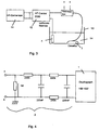
- the electrode of an ablation catheter produces the voltage signal shown in Fig. 1, which according to of the invention in the measuring structure shown in Fig. 2 was obtained.
- a catheter located in the bloodstream produces an initially very weak voltage signal, designated here U 0 , whereas an abrupt increase in voltage occurs when the catheter electrode contacts the tissue.
- the voltage signal obtained in this way represents, with its instantaneous value or amplitude, a measure of the quality of the catheter tissue contact and can be detected without the use of additional external currents. Consequently, no electrolytic processes will occur in the present invention, and it is to be understood that further measurements, such as the recording of ECG signals, will not be adversely affected.
- the tension is an extremely accurate measure of the Contact of the catheter electrode to the tissue, while a Impedance measurement during ablation only limited to the Closing tissue contact of the catheter, and on the other This signal occurs almost without any temporal Delay on which this is suitable for real-time measurement power.
- the height of the measured signal is very high exactly with the temperature of the tissue, in particular of the during an ablation of warming tissue, correlated.
- temperature values of the am Catheter adjacent tissue with an accuracy of +. / - 1 ° C were measurable.
- they were already simple Means, i. simple high-impedance Voltage measuring devices, accuracies of +/- 2 ° C measurable.
- the temperature was regularly linear with the measured voltage in proportion, which made it possible standardized voltage measurements the same Ablation catheter or a group of identical catheters assigned.
- the occurring voltage signal for controlling or monitoring the ablation process itself to use.
- the voltage signals during the delivery of the High frequency power detected, and falls below or exceeding the shutdown or at least the Reduction of the output of the high frequency power causes is always ensured that the high frequency power in was released into the patient's tissue, and it comes to a treatment with cooler overall Catheter electrodes and increased effect.
- the attending physician in further According to the invention design specify tissue depths, the associated with the temporal integral of the measured potentials become. It can then be the device of the invention either the entire ablation process after reaching the terminate, or can be used with catheters with multiple electrodes assigned to local sections of the Catheters within which the specified values are reached were turned off, or this lower power be supplied.
- Catheter with multiple ablation electrodes can be used the signal data of each particular electrode assigned, recorded, calculated and displayed, and it The treatment process can be local to the treatment site assigned programmable ended. This allows optimized for treatment already before the start of treatment Data can also be predefined locally, and it can an optimized in relation to the respective patient Treatment to be performed.
- the in Fig. 1 illustrated voltage signal with the Voltage measuring device 1, which is a low-pass filter. 2 was upstream, won.
- the voltage taps of the low-pass filter a and b were with Platinum electrodes of a bipolar catheter connected as it
- PCT / DE96 / 00638 has been described.
- the catheter 3 needs, however, to carry out the generally no additional means for detecting the catheter temperature, such as thermal sensors, though this is due to the Invention is not excluded.
- tapping the voltage to the Catheter electrodes a and b can also reduce the voltage between the one or more indifferent electrodes 4 and one of Electrodes a, b of the catheter 3 are detected, or the place associated with the respective catheter electrode a, b become.
- the low-pass filter 2 of the first invention Embodiment is with a storage oscilloscope of the type Hameg HM 1007 connected, which in the usual way a two-dimensional display device for temporal Representation of voltage curves represents.
- the signal shoulder 8, which is after the abrupt rise the signal edge 6 extends substantially flat, shows a temporal modulation based on the mechanical Catheter tissue contact between the catheter electrode b and the fabric 7 with respect to the indifferent electrode 4 or the electrode a may be attributed or with the Production and transport of chemical substances, which cause electrical potentials at the site of the catheter, related.
- the abrupt rise 6 and drop 9 of the signal edge shows however, the emergence and termination of a catheter / tissue contact with high security.
- the signal waveform for obtaining the signal waveform shown in FIG used construction is shown in Fig. 3 schematically in the form of a stationary Meß inconvenience, for standardization and calibration is usable, shown.
- An RF generator 11 is connected to the in of the PCT application cited above for the controlled delivery of RF power to the catheter 3, which has a plurality of ablation electrodes, connected and leads the electrodes of the catheter 3 pulsed High frequency power too.
- the high frequency power the catheter 3 also in time be fed continuously.
- the trough 13 can either with blood or with a suitable other Be filled with fluid in the body of the patient to simulate prevailing conditions.
- the indifferent electrode 4 and the electrodes a and b of the catheter 3 are platinum coated or consist of Platinum and are with just before its use Formalin or formaldehyde gas purified in such a way that in essentially no surface residue on the catheter or the indifferent electrode 4 remain.
- Fig. 5 compares the potential values according to the invention with temperatures which were detected at the same time at the location of the potential measurement; represents.
- the correspondence of the temperature value shown in dashed lines with the potential value 23 shown in a solid line agrees well with the model given above, since chemical potentials too are largely temperature-dependent.
- the potential decreases only to the increased value U 2 , which can be well explained by the presence of the above-discussed chemical substances.
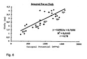
- Fig. 6 Another clear support of the explanatory model of the Potential development can be found in Fig. 6, according to which the Dependence of the depth of tissue in a patient at RF ablation produced lesions from the temporal integral the potential is represented. About one Temperature range of the ablation catheter above 20 ° C, namely from less than 55 ° C to more than 75 ° C Ablation temperature, these values are good with each other correlated. Consequently, in known Catheter features in many cases already the temporal Integral of the potential sufficient, without that in addition Temperature values should be detected to a suitable To receive information about the course of treatment.
- Such catheters could be based on thermal sensors dispense and therefore easier, cheaper and with be made smaller diameter.
- the Evaluation unit 15 can by the Evaluation unit 15 also one with the delivered power weighted or functionally linked measurement of Potential values, preferably in real time, made become.
- FIG. 2 A further embodiment according to the invention is shown in FIG. 2 represented in which the in the above cited PCT application described, pulsed generator 11 with the catheter 3 and its catheter electrodes a and b connected is.
- the catheter electrodes a and b are either the ablation electrodes themselves or in their vicinity arranged, associated with the respective Ablationselektroden Measuring electrodes, which are connected to the low-pass filter 2, which both the high frequency signal and Noise signal interference filters out.
- the downstream evaluation unit 15 includes the Voltage measuring device 1, as in the first Embodiment of the invention, a high-impedance Measuring input of at least more than 100 k ⁇ and preferably several M ⁇ input resistance to any additional current flow to the ablation process and of further measuring operations on a substantially no longer suppressible measurable value.
- a high-impedance voltage measurement a voltage measurement, when performing the ablation or the measurement of For example, ECG signals are no longer noticeable or not is more detectable.
- a storage oscilloscope with a Personal computer can be connected as a control device, the input resistance is about 1 M ⁇ , and its Input capacity is not more than 30 pF.
- the measured data obtained with the voltage measuring device 1 are recorded in the evaluation unit 15 and saved.
- the data can be either in real time or by reading from the memory of the evaluation unit 15 in two-dimensional shape shown on a display unit 21 and for comparison purposes or for the evaluation of the Treatment success are reproduced.
- the representation here can be used as instantaneous voltage signal, as a bar chart or any other, for the treating physician done ergonomically favorable manner.
- a control unit 16 assigned to the evaluation unit 15 can bring about the switching off or reduction of the power output by the HF generator 11 when the measured voltage signal falls below a predetermined value.
- Limit U g1 17 falls so as to prevent the catheter or its surroundings from being heated without producing the desired ablation.
- the limit value U g1 17 can be varied depending on the instantaneous ablation power or integrated delivered ablation power, ie, delivered ablation energy, and can thus be specified very precisely. As a result, contamination of the catheter is coagulated. Substances significantly reduced or avoided.
- the controller 16 at the beginning of the ablation process when exceeding a further limit value U g2 18 begin to integrate the output from the RF generator 11 power until the voltage signal either below the limit U g1 17 or below any other predetermined value drops.
- the size of the energy delivery into the tissue is detected, which allows the attending physician to make statements about the ablation effect.
- the treating the doctor with a visual or audible signal be given during the execution of the Treatment supported and further implementation of the Ablation, for example, based on ECG data, not with special needs.
- Control device 16 by means of an external computer or a personal computer 19 to realize.
- the invention is also not concerned with radiofrequency catheter ablation limited, but can at most other catheter ablation procedures with success Monitoring of the respective treatment success used become.
- Method for HF catheter ablation in which Tissue sections of a patient to be treated by Radiation of high frequency are ablated furthermore comprising a method as explained above for Detecting the contact between the catheter and the Patient tissue and / or the temperature of the Patient's tissue.
- Method for RF catheter ablation characterized in that the occurring voltage signal be visually and / or acoustically displayed, the visual display in the form of bar graphs, Real-time representation of the voltage signals in one two-dimensional coordinate system and / or in one Display of temporally integrated performance data.
Abstract
Description
Die Erfindung betrifft eine Vorrichtung zur Erfassung des Kontaktes eines in einem Gefäß eines Patienten, insbesondere in der Blutbahn eines Patienten, angeordneten Katheters zu dem Gewebe und ferner eine Vorrichtung zur Erfassung der Wechselwirkung von Hochfrequenzenergie mit dem Gewebe des Patienten.The invention relates to a device for detecting the contact of one in a vessel of a Patients, especially in the bloodstream of a patient, arranged catheter to the tissue and also a Device for detecting the Interaction of radio frequency energy with the tissue of the Patients.
Bei vielen medizinischen Anwendungen oder Behandlungen ist es für den Arzt von höchster Wichtigkeit, den Kontakt eines Instrumentes zu dem Körper des Patienten mit hoher Exaktheit zu erfassen, zu verfolgen und in manchen Fällen auch aufzuzeichnen, da hiervon häufig der Behandlungserfolg in wesentlichem Maße abhängt.In many medical applications or treatments is It is of the utmost importance to the doctor, the contact of one Instrument to the patient's body with high accuracy to capture, track and in some cases also since this is often the treatment success in essential extent.
Insbesondere bei der Katheterablation ist die erwünschte Behandlungswirkung in der Regel nur dann zu erzielen, wenn ein Kontakt zwischen dem Ablationkatheter und dem zu behandelnden Gewebe des Patienten während der gesamten Einwirkungsdauer der abgegebenen.Ablationsleistung sichergestellt werden kann.In particular, in catheter ablation is the desired Treatment effect usually only to be achieved if a contact between the ablation catheter and the treating the patient's tissue throughout Duration of action of delivered dissipation can be ensured.
Bisher wurden zur Erfassung des Katheter-Gewebekontaktes Widerstandsmessungen zwischen zumindest zwei Katheterelektroden oder den Katheterelektroden und einer amKörper des Patienten angeordneten indifferenten Elektrode vorgenommen. Diese Vorgehensweise ist jedoch, insbesondere bei der Hochfrequenz-Katheterablation, nachteilig, denn die Widerstandsmessung ist prinzipiell mit einem Stromfluß durch den zu messenden Bereich verbunden. Hierdurch werden aber zusätzliche Ströme bei der Ablation eingeführt, die, beispielsweise bei der Erfassung der EKG-Signale, äußerst störend sein können. Verwendet man Gleichstromwiderstandsmeßverfahren, um hochfrequente, die EKG-Erfassung beeinflussende Signale zu vermeiden, werden unerwünschte elektrolytische Wirkungen erzeugt, die zu einer weiteren chemischen Belastung des Patienten führen. Darüber hinaus sind Widerstandsmessungen überall da schwierig durchzufahren und störanfällig, wo korrosive. Einflüsse und Oberflächenverschmutzungen den Stromfluß behindern bzw. das Meßergebnis verfälschen. Eine derartige Situation liegt jedoch gerade im Bereich der medizinischen Anwendungen vor, da hier das Blut oder Körperflüssigkeiten des Patienten Salze bzw. koagulierende Substanzen aufweisen, die mit der Oberfläche von Elektroden oder Kontakten auf unerwünschte Weise wechselwirken können. Außerdem ist durch die Impedanzmessung während der Ablation der Gewebekontakt nur schwer zu beurteilen, da viele Faktoren den Impedanzwert beeinflussen können.So far, to detect the catheter-tissue contact Resistance measurements between at least two Catheter electrodes or the catheter electrodes and a indifferent electrode disposed on the body of the patient performed. However, this procedure is, in particular in radiofrequency catheter ablation, disadvantageous because the Resistance measurement is in principle with a current flow through connected to the area to be measured. But this will introduced additional currents during ablation, which, for example, in the detection of ECG signals, extremely can be disturbing. Using DC resistance measuring methods, to high-frequency, the ECG detection to avoid influencing signals produces undesirable electrolytic effects, the lead to further chemical stress on the patient. In addition, resistance measurements are everywhere difficult to drive through and prone to failure, where corrosive. Influences and surface contamination the current flow hamper or falsify the measurement result. Such However, the situation is precisely in the medical field Applications before, since here the blood or body fluids the patient has salts or coagulating substances, those with the surface of electrodes or contacts on can interact undesirably. It is also through the impedance measurement during tissue ablation ablation difficult to judge because many factors are the impedance value can influence.
So ist z.B. in dem Dokument WO 97/21387 (PCT/DE96/00638) eine Vorrichtung beschrieben, bei welcher mittels einer Messung der Impedanz der Katheterelektroden gegenüber einer am Patienten angeordneten indifferenten Elektrode Aufschluß über die richtige Lage des aktiven Katheterabschnitts relativ zu dem zu behandelnden Gewebe gewonnen wird. Hierzu wird die Impedanz der Elektroden in Bezug auf eine weitere Elektrode als Maß für den Gewebekontakt erfasst, angezeigt und/oder zeitlich zugeordnet gespeichert.For example, e.g. in the document WO 97/21387 (PCT / DE96 / 00638) a device described in which by means of a Measurement of the impedance of the catheter electrodes compared to a indifferent electrode arranged on the patient about the correct location of the active catheter section is obtained relative to the tissue to be treated. For this will be the impedance of the electrodes with respect to another Electrode detected as a measure of tissue contact and / or stored timed.
Ferner sind aus dem Dokument WO 96/41569 eine Vorrichtung und ein Verfahren zur thermischen Ablation bekannt, bei welchen eine Sondenspitze und eine Platte mit unterschiedlicher Austrittsarbeit verwendet werden, um eine galvanische Zelle zu bilden. Die galvanische Zelle wird mittels einer Nebenschlussimpedanz stark belastet, um einen Stromfluss zu erzeugen, mittels welchem ein Signal bereit gestellt wird, das die Gewebetemperatur an der Ablationsstelle reflektiert.Further, WO 96/41569 discloses a device and a method for thermal ablation, at which a probe tip and a plate with different work function can be used to one to form galvanic cell. The galvanic cell becomes heavily loaded by a shunt impedance to one To generate current flow, by means of which a signal ready which is the tissue temperature at the Ablation site reflects.
Der Erfindung liegt folglich die Aufgabe zugrunde, die vorstehend erwähnten Nachteile zu vermeiden und zu einer verbesserten Erfassung des Kontaktes zwischen Katheter und Gewebe des Patienten beizutragen.The invention is therefore the object of the to avoid the above-mentioned disadvantages and to a improved detection of contact between catheter and Contribute to the tissue of the patient.
Diese Aufgabe wird auf höchst überraschende Weise bereits
durch eine Vorrichtung
nach Anspruch 1 gelöst. This task is already done in a most surprising way
through a device
solved according to
Der Erfinder hat in überraschender Weise festgestellt, daß in vielen Fällen beim Anlegen von Elektroden an das Gewebe von Patienten, insbesondere bei blutumspülten Gewebe, Spannungen zwischen den Elektroden und insbesondere während der HF-Ablation auftreten. Die vorzugsweise metallische Elektrode eines Ablationskatheters erzeugt beispielsweise das in Fig. 1 dargestellte Spannungssignal, welches gemäß der Erfindung in dem in Fig. 2 dargestellten Meßaufbau erhalten wurde.The inventor has surprisingly found that in many cases when applying electrodes to the tissue of patients, especially in blood-soaked tissue, Tensions between the electrodes and especially during the RF ablation occur. The preferably metallic For example, the electrode of an ablation catheter produces the voltage signal shown in Fig. 1, which according to of the invention in the measuring structure shown in Fig. 2 was obtained.
Auf höchst überraschende Weise hat der Erfinder festgestellt, daß ein in der Blutbahn angeordnetes Katheter ein hier mit U0 bezeichnetes, zunächst nur sehr schwaches Spannungssignal erzeugt, wohingegen ein abrupter Spannungsanstieg dann erfolgt, wenn die Katheterelektrode mit dem Gewebe in Kontakt tritt. Das hierbei gewonnene Spannungssignal stellt mit dessen Momentanwert bzw. Amplitude ein Maß für die Güte des Katheter-Gewebekontaktes dar und kann ohne Verwendung zusätzlicher äußerer Ströme erfaßt werden. Folglich werden in erfindungsgemäßer Weise keine elektrolytischen Vorgänge auftreten, und es ist davon auszugehen, daß weitere Messungen, wie beispielsweise die Aufzeichnung von EKG-Signalen, nicht negativ beeinflußt werden.Most surprisingly, the inventor has found that a catheter located in the bloodstream produces an initially very weak voltage signal, designated here U 0 , whereas an abrupt increase in voltage occurs when the catheter electrode contacts the tissue. The voltage signal obtained in this way represents, with its instantaneous value or amplitude, a measure of the quality of the catheter tissue contact and can be detected without the use of additional external currents. Consequently, no electrolytic processes will occur in the present invention, and it is to be understood that further measurements, such as the recording of ECG signals, will not be adversely affected.
Darüber hinaus hat es sich gezeigt; daß die erfindungsgemäße Spannungsmessung der herkömmlichen Widerstandsmessung auch in Bezug auf die gewonnenen Meßdaten deutlich überlegen ist. Zum einen ist die Spannung ein äußerst genaues Maß für den Kontakt der Katheterelektrode zum Gewebe, während eine Impedanzmessung während der Ablation nur bedingt auf den Gewebekontakt des Katheters schließen läßt, und zum anderen tritt dieses Signal nahezu ohne jegliche zeitliche Verzögerung auf, welches dieses zur Echtzeitmessung geeignet macht.In addition, it has been shown; that the inventive Voltage measurement of conventional resistance measurement, too is clearly superior in terms of the measured data obtained. On the one hand, the tension is an extremely accurate measure of the Contact of the catheter electrode to the tissue, while a Impedance measurement during ablation only limited to the Closing tissue contact of the catheter, and on the other This signal occurs almost without any temporal Delay on which this is suitable for real-time measurement power.
Auf besonders überraschende Weise hat sich ferner herausgestellt, däß die Höhe des gemessenen Signals sehr exakt mit der Temperatur des Gewebes, insbesondere des während einer Abladierung sich erwärmenden Gewebes, korreliert. Mit parallelen Meßverfahren konnte gezeigt werden, daß mit der Erfindung Temperaturwerte des am Katheter anliegenden Gewebes mit einer Genauigkeit von +./- 1 °C meßbar waren. Ferner waren bereits mit einfachen Mitteln, d.h. einfachen hochohmigen Spannungsmeßeinrichtungen, Genauigkeiten von +/- 2 °C meßbar. Hierbei stand die Temperatur regelmäßig linear mit der gemessenen Spannung im Verhältnis, welches es ermöglichte, standardisierte Spannungsmeßwerte demselben Ablationskatheter oder einer Gruppe baugleicher Katheter zuzuordnen.In a particularly surprising way has further The height of the measured signal is very high exactly with the temperature of the tissue, in particular of the during an ablation of warming tissue, correlated. With parallel measuring methods could be shown be that with the invention, temperature values of the am Catheter adjacent tissue with an accuracy of +. / - 1 ° C were measurable. Further, they were already simple Means, i. simple high-impedance Voltage measuring devices, accuracies of +/- 2 ° C measurable. Here, the temperature was regularly linear with the measured voltage in proportion, which made it possible standardized voltage measurements the same Ablation catheter or a group of identical catheters assigned.
Da Spannungen prinzipiell auch stromfrei meßbar sind, beispielsweise durch Aufprägen einer gleichhohen Gegenspannung oder durch Messung mit sehr hochohmigen Meßverstärkern, spielen Übergangswiderstände von Kontakten innerhalb der Meßstrecke eine weit weniger wichtige Rolle als bei allen herkömmlichen Meßverfahren. Folglich ist die erfindungsgemäße Vorrichtung bzw. das erfindungsgemäße Verfahren gegenüber den herkömmlichen Verfahren weniger Störungen ausgesetzt und zuverlässiger sowie sicherer anwendbar. Darüberhinaus scheinen thermische (Durchgangs-) Widerstände sowie thermische Kapazitäten des Katheters selbst weit geringere Einflüsse auf die Genauigkeit sowie Geschwindigkeit der Messung der Temperatur zu haben.Since voltages are principally measurable without current, for example, by imprinting an equal height Counter voltage or by measurement with very high impedance Amplifiers, play contact resistance of contacts within the measuring section a far less important role as in all conventional measuring methods. Consequently, the Inventive device or the invention Method less than conventional methods Disrupted and more reliable and safer applicable. In addition, thermal (transit) Resistors and thermal capacity of the catheter even far lower influences on accuracy as well Speed of measuring the temperature.
Auf weiter höchst überraschende Weise hat sich bei der Katheterablation selbst herausgestellt, daß deren Ergebnisse erheblich verbessert werden konnten. Wird beispielsweise wie bei der herkömmlichen Kathetertemperatursteuerung die Kathetertemperatur als Regelgröße und somit als Maß für die Energieabgabe verwendet, kann es vorkommen, daß bei relativ kaltem Katheter, beispielsweise bei einer Temperatur von nur etwa 40 °C, bereits dann eine deutliche Läsion im Gewebe hervorgerufen wird, wenn der Katheter in sehr engem Kontakt mit dem Gewebe stand und hierdurch einen großen Teil der Ablationsenergie in dieses leiten konnte.In a further highly surprising way, at the Catheter ablation itself revealed that its results could be significantly improved. For example, how in conventional catheter temperature control the Catheter temperature as a controlled variable and thus as a measure of the Energy used, it may happen that at relative cold catheter, for example at a temperature of only about 40 ° C, already a significant lesion in the tissue is caused when the catheter in very close contact with the fabric and thereby a large part of the Could conduct ablation energy into this.
Die herkömmliche, reine Temperatursteuerung mit thermischen Sensoren hätte in diesem Fall die Läsion nicht erfaßt. Darüber hinaus kann es selbst bei hoher Kathetertemperatur dann zu nur geringer Läsions- bzw. Ablationswirkung kommen, wenn der Katheter-Gewebekontakt sehr schlecht ist. In beiden Fällen konnte es bei den herkömmlichen Verfahren und Vorrichtungen zu einer ungenauen bzw. falschen Aussage über den Behandlungserfolg kommen.The conventional, pure temperature control with thermal Sensors would not have detected the lesion in this case. In addition, it can even at high catheter temperature then only slight lesion or ablation effect occur, if the catheter-tissue contact is very bad. In both Cases it could with the conventional procedures and Devices to an inaccurate or incorrect statement about come the treatment success.
Bei der Erfindung wird jedoch davon ausgegangen, daß durch die auftretenden und erfaßten Spannungssignale stets sichergestellt wird, daß die Energieabgabe im wesentlichen in das Gewebe erfolgt, und folglich kann bei der Erfindung die vom Katheter abgegebene Leistung direkt und exakter einer Behandlungswirkung zugeordnet werden. Ferner kann, nachdem der abrupte Spannungsanstieg den Katheter/Gewebekontakt erfaßt hat, die absolute Höhe des Spannungssignals zur sehr genauen Temperaturmessung benutzt werden.In the invention, however, it is assumed that by the occurring and detected voltage signals always It is ensured that the energy tax substantially into the tissue, and consequently, in the invention the output from the catheter directly and accurately associated with a treatment effect. Furthermore, after the abrupt increase in voltage contacts the catheter / tissue has detected the absolute height of the Voltage signal used for very accurate temperature measurement become.
Weiterhin ist es möglich, das auftretende Spannungssignal zur Steuerung bzw. Überwachung des Ablationsvorgangs selbst zu verwenden. Werden beispielsweise bei der Hochfrequenz-Ablation die Spannungssingale während der Abgabe der Hochfrequenzleistung erfaßt, und wird bei Unterschreiten bzw. Überschreiten die Abschaltung oder zumindest die Verminderung der Abgabe der Hochfrequenzleistung bewirkt, wird stets gewährleistet, daß die Hochfrequenzleistung im wesentlichen in das Patientengewebe abgegeben wurde, und es kommt zu einer Behandlung mit insgesamt kühleren Katheterelektroden und erhöhter Wirkung.Furthermore, it is possible, the occurring voltage signal for controlling or monitoring the ablation process itself to use. For example, in high-frequency ablation the voltage signals during the delivery of the High frequency power detected, and falls below or exceeding the shutdown or at least the Reduction of the output of the high frequency power causes is always ensured that the high frequency power in was released into the patient's tissue, and it comes to a treatment with cooler overall Catheter electrodes and increased effect.
Es ist darüberhinaus vorteilhaft, das Spannungssignal zu integrieren und somit zu einer Aussage über die Wechselwirkung, d. h. über die einwirkende Temperatur und die Zeit der Behandlung, zu gelangen.It is also advantageous to the voltage signal integrate and thus to a statement about the Interaction, d. H. about the acting temperature and the time of treatment to arrive.
Darüber hinaus treten Verschmutzungen des Katheters durch Koagulation wegen der nunmehr aufgrund der exakteren Messung möglich gewordenen niedrigeren Kathetertemperaturen nur in sehr viel geringerem Maße auf, und es wird ein durch derartige Verschmutzungen verursachter Behandlungsabbruch mit der damit einhergehenden erhöhten Patientenbelastung vermieden. In addition, contamination of the catheter occur Coagulation because of now due to the more accurate measurement become possible lower catheter temperatures only in to a much lesser extent, and it gets a through Such contamination caused treatment interruption with the concomitant increased patient burden avoided.
Wird die Abschaltung oder zumindest die Verminderung der Abgabe der Hochfrequenzleistung bei einem raschen Anstieg oder Abfall der Potentialwerte bewirkt, kann hierdurch auch die Vaporisierung des zu behandelnden Gewebes verhindert oder zumindest stark beschränkt werden, da nunmehr eine sehr schnelle Regelung möglich ist und es nicht mehr zur ungewollten Überhitzung des Gewebes kommt.Will the shutdown or at least the reduction of Delivering the high frequency power at a rapid increase or drop in the potential values, this can also be done prevents vaporization of the tissue to be treated or at least severely limited, since now a very fast regulation is possible and it is no longer for unwanted overheating of the tissue comes.
In höchst überraschender Weise hat sich ferner herausgestellt, daß die erfindungsgemäßen Potentiale bzw. Spannungssignale während der Durchführung der Hochfrequenz-Ablation, unabhängig davon, ob die Hochfrequenzsignale zur Ablation entweder kontinuierlich oder gepulst angelegt werden, stets sehr sicher erfaßt werden können. Wird die von dem Katheter abgegebene Hochfrequenzleistung zeitlich integriert, solange die Spannungssignale oberhalb eines vorgebbaren Grenzwertes liegen, welcher sicherstellt, daß ein Katheter/Gewebekontakt vorhanden ist, und wird die integrierte Leistung als bis zu diesem Zeitpunkt in das Gewebe abgegebene Ablationsenergie berechnet, kann dem behandelnden Arzt nicht nur das Fortschreiten des Behandlungserfolges angezeigt werden, sondern es kann mit einer entsprechend programmierten Steuereinrichtung die Behandlung bei Erreichen eines vorgegebenen Energiewertes automatisiert durch Abschaltung oder Verminderung der Hochfrequenzleistung beendet werden. Hierdurch kann eine weit höhere Behandlungssicherheit bereitgestellt werden, als dies bei den bisherigen Verfahren möglich war. Erstmalig ist es hierdurch möglich, bereits im Verlauf der Behandlung die Ablationswirkung durch Integration der abgegebenen Leistung zu erfassen und dem behandelnden Arzt in Echtzeit anzuzeigen.In a most surprising way, further that the potentials or Voltage signals during the performance of high-frequency ablation, regardless of whether the high frequency signals to Ablation applied either continuously or pulsed will always be very secure. Will the of the radiofrequency power delivered to the catheter in time integrated as long as the voltage signals above a predetermined limit, which ensures that a catheter / tissue contact is present, and will the integrated performance than at that time in the Calculated tissue ablation energy can, the doctor not only the progression of the Treatment success can be displayed, but it can with a correspondingly programmed control device the Treatment on reaching a given energy value automated by switching off or reducing the Radio frequency power to be stopped. This can be a far greater treatment security than when this was possible with the previous methods. For the first time it thereby possible, already in the course of treatment the Ablation effect through integration of the delivered power to record and to the attending physician in real time display.
Darüberhinaus kann der behandelnde Arzt in weiterer erfindungsgemäßer Ausgestaltung Gewebetiefen vorgeben, die dem zeitlichen Integral der gemessenen Potentiale zugeordnet werden. Es kann dann die erfindungsgemäße Vorrichtung entweder den gesamten Ablationsvorgang nach Erreichen des vorgegebenen Wertes beenden, oder es können bei Kathetern mit mehreren Elektroden lokal zugeordnet Abschnitte des Katheters, innerhalb derer die vorgegebenen Werte erreicht wurden, abgeschaltet oder diesen geringere Leistung zugeführt werden.In addition, the attending physician in further According to the invention design specify tissue depths, the associated with the temporal integral of the measured potentials become. It can then be the device of the invention either the entire ablation process after reaching the terminate, or can be used with catheters with multiple electrodes assigned to local sections of the Catheters within which the specified values are reached were turned off, or this lower power be supplied.
Werden hierzu in bevorzugter erfindungsgemäßer Weise Katheter mit mehreren Ablationselektroden verwendet, können die Signaldaten der jeweiligen speziellen Elektrode zugeordnet, erfaßt, berechnet sowie angezeigt werden, und es kann der Behandlungsablauf lokal dem Behandlungsort zugeordnet programmierbar beendet werden. Hierdurch können bereits vor Behandlungsbeginn für die Behandlung optimierte Daten auch lokal zugeordnet vorgegeben werden, und es kann eine in Bezug auf den jeweiligen Patienten optimierte Behandlung durchgeführt werden.For this purpose in a preferred inventive way Catheter with multiple ablation electrodes can be used the signal data of each particular electrode assigned, recorded, calculated and displayed, and it The treatment process can be local to the treatment site assigned programmable ended. This allows optimized for treatment already before the start of treatment Data can also be predefined locally, and it can an optimized in relation to the respective patient Treatment to be performed.
Die Erfindung wird nachfolgend anhand bevorzugter
Ausführungsformen und unter Bezugnahme auf die beigefügten
Zeichnungen detaillierter beschrieben.
Es zeigen:
- Fig. 1
- die Signalform der erfindungsgemäßen Spannung, wie sie bei einem zeitlich begrenzten Katheterelektroden-Gewebekontakt in einem System mit indifferenter Platinelektrode sowie Platin-Katheterelektrode auftritt,
- Fig. 2
- eine schematische Darstellung zur Durchführung der Erfindung mit einem Katheter sowie einer Vorrichtung, die beispielsweise der in der PCT/DE96/00638 beschriebenen entspricht, jedoch in erfindungsgemäßer Weise weiter ausgestaltet wurden,
- Fig. 3
- einen Labor Meßaufbau zur Standardisierung bzw. Eichung sowie Meßdatengewinnung vermittels eines Schweineherzens,
- Fig. 4
- ein Tiefpaßfilter, welches bereits zusammen mit einem Oszilloskop zur Gewinnung der erfindungsgemäßen Spannungssignale verwendbar ist,
- Fig. 5
- einen Vergleich der erfindungsgemäß gewonnenen Potentialwerte mit lokal zugeordneten, an einem Ablationskatheter gewonnenen Temperaturwerten während der Katheterablation in einem lebenden Herzen,
- Fig. 6
- einen Vergleich der Werte des zeitlichen Integrals der erfindungsgemäß gewonnenen Potentialwerte mit bei der Katheterablation erreichten Läsionstiefen bei verschiedenen Temperaturen des Ablationskatheters.
Show it:
- Fig. 1
- the waveform of the voltage according to the invention, as occurs in a temporary catheter electrode tissue contact in a system with indifferent platinum electrode and platinum catheter electrode,
- Fig. 2
- 1 is a schematic representation for carrying out the invention with a catheter and a device which corresponds, for example, to that described in PCT / DE96 / 00638, but has been designed further in accordance with the invention;
- Fig. 3
- a laboratory measuring setup for standardization or calibration as well as data acquisition by means of a pig heart,
- Fig. 4
- a low-pass filter, which is already usable together with an oscilloscope for obtaining the voltage signals according to the invention,
- Fig. 5
- a comparison of the potential values obtained according to the invention with locally assigned temperatures obtained at an ablation catheter during catheter ablation in a living heart,
- Fig. 6
- a comparison of the values of the temporal integral of the potential values obtained according to the invention with lesion depths achieved during catheter ablation at different temperatures of the ablation catheter.
Die Erfindung wird nachfolgend unter Bezugnahme auf bevorzugte Ausführungsformen und zunächst unter Bezugnahme auf die Fig. 1 und 4 dargestellt.The invention will be described below with reference to preferred embodiments and first with reference to FIGS. 1 and 4.
In einer ersten, zunächst zur Erläuterung äußerst einfach
gehaltenen erfindungsgemäßen Ausführungsform wird das in
Fig. 1 dargestellte Spannungssignal mit der
Spannungsmeßvorrichtung 1, der ein Tiefpaßfilter 2
vorgeschaltet wurde, gewonnen.In a first, for the sake of explanation, extremely simple
held embodiment of the invention, the in
Fig. 1 illustrated voltage signal with the
Die Spannungsabgriffe des Tiefpaßfilters a und b wurden mit
Platinelektroden eines bipolaren Katheters verbunden, wie es
beispielsweise in der PCT/DE96/00638 beschrieben wurde.
Das Katheter 3 braucht- jedoch für die Durchführung der
vorliegenden Erfindung generell keine zusätzlichen Mittel
zur Erfassung der Kathetertemperatur, wie beispielsweise
thermische Sensoren, aufzuweisen, obwohl dies durch die
Erfindung nicht ausgeschlossen wird.The voltage taps of the low-pass filter a and b were with
Platinum electrodes of a bipolar catheter connected as it
For example, in PCT / DE96 / 00638 has been described.
The
Alternativ zum Abgriff der Spannung an den
Katheterelektroden a und b kann die Spannung auch zwischen
der oder den indifferenten Elektroden 4 und einer der
Elektroden a, b des Katheters 3 erfaßt werden, oder dem Ort
der jeweiligen Katheterelektrode a, b zugeordnet erfaßt
werden.Alternatively to tapping the voltage to the
Catheter electrodes a and b can also reduce the voltage between
the one or more
Das Tiefpaßfilter 2 der ersten erfindungsgemäßen
Ausführungsform ist mit einem Speicheroszilloskop des Typs
Hameg HM 1007 verbunden, welches in gewohnter Weise eine
zweidimensionale Anzeigevorrichtung.zur zeitlichen
Darstellung von Spannungsverläufen darstellt.The low-
Hiermit wurde zunächst mit dem in Fig. 3 dargestellten
Meßaufbau die in Fig. 1 gezeigte Signalform des zeitlichen
Spannungsverlaufs erhalten, die Zeitbasis betrug 20s
TIME/DIV und die angezeigte Spannung entsprach 10mV
VOLTS/DIV. Der zunächst niedrige,ebene Abschnitt 5 des
Grundsignals Uo stellt die Spannung bei im Blutstrom
befindlichem Katheter 3 dar und zeigt eine deutlich
ausgeprägte Signalflanke 6, sobald das Katheter 3 mit Gewebe
7 in Kontakt tritt.This was first with that shown in Fig. 3
Meßaufbau the waveform shown in Fig. 1 of the temporal
Voltage course obtained, the time base was 20s
TIME / DIV and the displayed voltage corresponded to 10mV
VOLTS / DIV. The initially low,
Die Signalschulter 8, welche sich nach dem abrupten Anstieg
der Signalflanke 6 im wesentlichen eben erstreckt, zeigt
eine zeitliche Modulation, die auf den mechanischen
Katheter-Gewebekontakt zwischen der Katheterelektrode b und
dem Gewebe 7 in Bezug auf die indifferente Elektrode 4 oder
die Elektrode a zurückzuführen sein kann oder mit der
Erzeugung und dem Transport chemischer Substanzen, welche
elektrische Potentiale am Ort des Katheters hervorrufen,
zusammenhängen.The
Wird der Katheter vom Gewebe entfernt, kommt es zur
abfallenden Signalflanke 9, die in ein gegenüber dem
Grundsignal 0 leicht erhöhtes Grundsignal U2 abklingend
übergeht.If the catheter is removed from the tissue, the
Der abrupte Anstieg 6 sowie Abfall 9 der Signalflanke zeigt
jedoch das Entstehen sowie Beenden eines Katheter/Gewebekontaktes
mit hoher Sicherheit an.The
Der zur Gewinnung der in Fig. 1 dargestellten Signalform
verwendete Aufbau ist in Fig. 3 schematisch in Form eines
stationären Meßaufbaus, der zur Standardisierung und Eichung
verwendbar ist, gezeigt. Ein HF-Generator 11 ist mit dem in
der vorstehend zitierten PCT-Anmeldung beschriebenen Gerät
zur kontrollierten Abgabe von HF-Leistung an den Katheter 3,
welcher mehrere Ablationselektroden aufweist, verbunden und
führt den Elektroden des Katheters 3 gepulste
Hochfrequenzleistung zu.The signal waveform for obtaining the signal waveform shown in FIG
used construction is shown in Fig. 3 schematically in the form of a
stationary Meßaufbau, for standardization and calibration
is usable, shown. An
In alternativen erfindungsgemäßer Ausgestaltung kann jedoch
die Hochfrequenzleistung dem Katheter 3 auch zeitlich
kontinuierlich zugeführt werden.In alternative inventive embodiment, however
the high frequency power the
Innerhalb eines Trogs 13 sind die indifferente Elektrode 4
sowie Gewebe 7 angeordnet, an welchem mittels des Katheters
3 Ablationsvorgänge vorgenommen werden. Der Trog 13 kann
entweder mit Blut oder mit einer geeigneten anderen
Flüssigkeit gefüllt sein, um die im Körper des Patienten
herrschenden Bedingungen zu simulieren.Within a
Die indifferente Elektrode 4 sowie die Elektroden a und b
des Katheters 3 sind platinbeschichtet oder bestehen aus
Platin und werden unmittelbar vor dessen verwendung mit
Formalin oder Formaldehydgas derart gereinigt, daß im
wesentlichen keinerlei Oberflächenrückstände am Katheter
bzw. der indifferenten Elektrode 4 verbleiben.The
Es hat sich herausgestellt, daß die Reinigung mit Formalin bzw. Formaldehydgas zu sehr guten und genau reproduzierbaren Meßergebnissen führte, welche über einen Zeitraum von mehreren Tagen sehr exakt nachvollziehbar waren. Jedoch liegt es im Rahmen der Erfindung, auch andere Reinigungsverfahren zu verwenden, um zu einer im wesentlichen rückstandsfreien Elektrodenoberfläche zu gelangen. Bei sterilisierten Kathetern können auch über sehr viel längere Zeiträume sehr gute Meßergebnisse erhalten werden.It has been found that purification with formalin or formaldehyde gas to very good and exactly reproducible Measurement results, which over a period of several days were very accurately traceable. however it is within the scope of the invention, others To use cleaning method to one in the essential residue-free electrode surface reach. With sterilized catheters can also over very obtained very good results for much longer periods become.
Ferner wird auch die Verwendung anderer Metalle bzw. chemischer Substanzen, die in der Lage sind; die erfindungsgemäße Spannung oder ähnliche, beim Inkontakttreten und/oder Inkontaktstehen der Katheterelektroden mit dem Gewebe auftretender Spannungen zu erzeugen, nicht ausgeschlossen. Hierzu wird in erfindungsgemäßen Sinne jedoch ohne Beschränkung der Allgemeinheit davon ausgegangen, daß während der Katheterablation freie Radikale oder zumindest chemische Substanzen erzeugt werden, welche die erfindungsgemäßen Potentiale hervorrufen. Wird ferner davon ausgegangen, daß bei starker Wechselwirkung der Hochfrequenzleistung mit dem Gewebe ein vermehrter Austritt der vorstehend erwähnten Substanzen aus dem Gewebe stattfindet, kann die erfindungsgemäße Vorrichtung direkt Aussagen über die im Gewebe erzeugte Schädigung bzw. Läsionswirkung bereitstellen.Furthermore, the use of other metals or chemical substances that are able; the tension according to the invention or the like, in Contacting and / or contacting the Catheter electrodes with the tissue occurring voltages too generate, not excluded. This is done in According to the invention, however, without limitation Generality assumed that during the Catheter ablation free radicals or at least chemical Substances are generated which are the inventive Create potentials. It is further assumed that with strong interaction of the high frequency power with the Tissue an increased leakage of the aforementioned Substances taking place from the tissue, the Device according to the invention directly statements in the Tissue damage or lesion effect provide.
Nachfolgend wird auf Fig. 5 Bezug genommen, welche den
Vergleich der erfindungsgemäßen Potentialwerte mit
Temperaturen, die zeitgleich am Ort der Potentialmessung
erfaßt wurden; darstellt. Die Übereinstimmung des
gestrichelt dargestellten Temperaturwertes mit dem
durchgezogen dargestellten Potentialwert 23 stimmt
erwartungsgemäß mit dem vorstehend angegebenen Modell gut
überein, da auch chemische Potentiale weitgehend
temperaturabhängig sind. Fällt jedoch die Temperatur nach
der Behandlung wieder ab, wie auf der rechten Seite von Fig.
5 dargestellt, so sinkt das Potenial nur auf den erhöhten
Wert U2 ab, der durch das Vorhandensein der vorstehend
diskutierten chemischen Substanzen gut erklärbar ist.Reference is now made to Fig. 5, which compares the potential values according to the invention with temperatures which were detected at the same time at the location of the potential measurement; represents. As expected, the correspondence of the temperature value shown in dashed lines with the
Eine Unterscheidung zwischen Verlust des mechanischen Kontaktes und Abfall der Temperatur ist leicht dadurch möglich, daß die abgegebene Leistung erfaßt und hieraus ein Schwellenwert gebildet wird. Dieser Schwellenwert gibt den minimal zu erwartenden Spannungswert an und kann bei Unterschreitung die Abschaltung der Abgabe von Ablationsenergie bewirken.A distinction between loss of mechanical Contact and drop of temperature is easy by possible that the delivered power detected and from this Threshold is formed. This threshold gives the minimum expected voltage and can at Below the shutdown of the delivery of Effect ablation energy.
Eine weitere deutliche Stützung des Erklärungsmodells der Potentialentstehung findet sich in Fig. 6, gemäß welcher die Abhängigkeit der Tiefe der im Gewebe eines Patienten bei der HF-Ablation erzeugten Läsionen von dem zeitlichen Integral der auftretenden Poteniale dargestellt ist. Über einen Temperaturbereich des Ablationskatheters von über 20 °C, nämlich von weniger als 55 °C bis zu mehr als 75 °C Ablationstemperatur, sind diese Werte gut miteinander korreliert. Folglich kann bei bekannten Kathetereigenschaften in vielen Fällen bereits das zeitliche Integral des Potentials ausreichen, ohne daß zusätzlich Temperaturwerte erfaßt werden müßten, um eine geeignete Aussage über den Behandlungsverlauf zu erhalten.Another clear support of the explanatory model of the Potential development can be found in Fig. 6, according to which the Dependence of the depth of tissue in a patient at RF ablation produced lesions from the temporal integral the potential is represented. About one Temperature range of the ablation catheter above 20 ° C, namely from less than 55 ° C to more than 75 ° C Ablation temperature, these values are good with each other correlated. Consequently, in known Catheter features in many cases already the temporal Integral of the potential sufficient, without that in addition Temperature values should be detected to a suitable To receive information about the course of treatment.
Derartige Katheter könnten auf thermische Sensoren verzichten und folglich einfacher, kostengünstiger und mit geringerem Durchmesser hergestellt werden.Such catheters could be based on thermal sensors dispense and therefore easier, cheaper and with be made smaller diameter.
Es liegt darüberhinaus im Rahmen der Erfindung, für einfachere Ausführungsformen die abgegebene Leistung des HF-Ablationsgenerators ohne Temperaturmessung derart zu beschränken, daß vorgegebene Maximaltemperaturen niemals überschritten werden, so daß auch in diesem Falle eine Unterdrückung von unerwünschten Koagulationsvorgängen sowie eine Vaporisierung von Gewebe unterbleibt.It is also within the scope of the invention, for simpler embodiments the output power of the RF ablation generator without temperature measurement so too restrict that given maximum temperatures never be exceeded, so that in this case, too Suppression of unwanted coagulation processes as well a vaporization of tissue is omitted.
Um die Genauigkeit der Messung bzw. die Korrelation der in
Fig. 6 dargestellten Größen zu verbessern, kann durch die
Auswertungseinheit 15 auch eine mit der abgegebenen Leistung
gewichtete oder funktional verknüpfte Messung der
Potentialwerte, vorzugsweise in Echtzeit, vorgenommen
werden.To the accuracy of the measurement or the correlation of in
Fig. 6 shown to improve, can by the
Eine weitere erfindungsgemäße Ausführungsform ist in Fig. 2
dargestellt, in welcher der in der vorstehend zitierten PCT-Anmeldung
beschriebene, gepulst betriebene Generator 11 mit
dem Katheter 3 sowie dessen Katheterelektroden a und b
verbunden ist. Die Katheterelektroden a und b sind entweder
die Ablationselektroden selbst oder in deren Nähe
angeordnete, den jeweiligen Ablationselektroden zugeordnete
Meßelektroden, die mit dem Tiefpaßfilter 2 verbunden sind,
welches sowohl das Hochfrequenzsignal als auch
Brummsignalstörungen ausfiltert.A further embodiment according to the invention is shown in FIG. 2
represented in which the in the above cited PCT application
described,
Die nachgeschaltete Auswertungseinheit 15 umfaßt die
Spannungsmeßeinrichtung 1, die wie bei der ersten
erfindungsgemäßen Ausführungsform einen hochohmigen
Meßeingang von wenigstens mehr als 100 kΩ und vorzugsweise
mehreren MΩ Eingangswiderstand aufweist, um jeglichen
zusätzlichen Stromfluß zum Ablationsvorgang sowie von
weiteren Meßvorgängen auf einen im wesentlichen nicht mehr
meßbaren Wert zu unterdrücken. In erfindungsgemäßem Sinne
ist eine hochohmige Spannungsmessung eine Spannungsmessung,
die bei der Durchführung der Ablation oder der Messung von
beispielsweise EKG-Signalen nicht mehr auffällt bzw. nicht
mehr nachweisbar ist.The
Bei einer besonders bevorzugten Ausführungsform, beispielsweise einem Speicheroszilloskop, das mit einem Personal-Computer als Steuereinrichtung verbunden sein kann, weist der Eingangswiderstand etwa 1 MΩ auf, und dessen Eingangskapazität beträgt nicht mehr als 30 pF.In a particularly preferred embodiment, For example, a storage oscilloscope with a Personal computer can be connected as a control device, the input resistance is about 1 MΩ, and its Input capacity is not more than 30 pF.
Die mit der Spannungsmeßvorrichtung 1 gewonnenen Meßdaten
werden in der Auswertungseinheit 15 aufgezeichnet und
gespeichert. Die Daten können entweder in Echtzeit oder
durch Auslesen aus dem Speicher der Auswertungseinheit 15 in
zweidimensionaler Form an einer Anzeigeinheit 21 dargestellt
und etwa zu Vergleichszwecken oder zur Bewertung des
Behandlungserfolgs wiedergegeben werden.The measured data obtained with the
Die Darstellung kann hierbei als momentanes Spannungssignal, als Balkendiagramm oder auf beliebige andere, für den behandelnden Arzt ergonomisch günstige Weise erfolgen.The representation here can be used as instantaneous voltage signal, as a bar chart or any other, for the treating physician done ergonomically favorable manner.
Ferner kann eine der Auswertungseinheit 15 zugeordnete
Steuereinrichtung 16 die Abschaltung oder Verminderung der
vom HF-Generator 11 abgegebenen Leistung bewirken, wenn das
gemessene Spannungssignal unter einen vorgegebenen. Grenzwert
Ug1 17 fällt, um derart zu verhindern, daß der Katheter oder
dessen Umgebung aufgeheizt wird, ohne hierbei die gewünschte
Ablation zu erzeugen. Der Grenzwert Ug1 17 kann in
Abhängigkeit von der jeweils abgegebenen momentanen
Ablationsleistung oder integrierten abgegebenen
Ablationsleistung, d.h. abgegebenen Ablationsenergie,
verändert und somit sehr genau vorgegeben werden. Hierdurch
wird eine Verschmutzung des Katheters durch koagulierte.
Substanzen in erheblichem Maße vermindert bzw. vermieden.Furthermore, a control unit 16 assigned to the
Darüber hinaus kann die Steuereinrichtung 16 zu Beginn des
Ablationsvorgangs beim Überschreiten eines weiteren
Grenzwertes Ug2 18 beginnen, die vom HF-Generator 11
abgegebene Leistung so lange zu integrieren, bis das
Spannungssignal entweder unter den Grenzwert Ug1 17 oder
unter einen beliebigen anderen vorgebbaren Wert abfällt.
Hierdurch wird die der Energieabgabe in das Gewebe
zugeordnete Größe erfaßt, die es dem behandelnden Arzt
gestattet, Aussagen über die Ablationswirkung zu treffen.
Ferner liegt es im Rahmen der Erfindung, die Integration der
vom HF-Generator abgegebenen Leistung 11 mit der Höhe des
Spannungssignals multipliziert durchzufahren, um zu einer
verbesserten oder korrigierten Aussage über die
Ablationswirkung zu gelangen.In addition, the controller 16 at the beginning of the ablation process when exceeding a further limit value U g2 18 begin to integrate the output from the
Es liegt ebenfalls im Rahmen der Erfindung, weitere
Funktionswerte in Abhängigkeit von der momentanen Spannung U1
bei der Integration der vom HF-Generator abgegebenen
Leistung mit zu berücksichtigen, wie beispielsweise die bei
Standardmessungen ermittelten tabellarischen Funktionswerte
der Läsionswirkung für einen standardisierten Katheter 3
bzw. einen individuellen Katheter 3. It is also within the scope of the invention to take into account further functional values as a function of the instantaneous voltage U 1 during the integration of the power delivered by the HF generator, such as the tabular function values of the lesion effect determined for standard measurements for a
Steht ein gewonnener Parametersatz für einen bestimmten Kathetertyp oder ein individuelles Katheter zur Erfassung der Läsionswirkung zur Verfügung, kann auch die Tiefe der Läsion als Funktion der abgegebenen Energie dargestellt und zur Abschaltung des Läsionsvorgangs verwendet werden. Hierdurch wird dem behandelnden Arzt der jeweiligen Katheterelektrode zugeordnet die Möglichkeit gegeben, örtlich verschiedene Tiefen bzw. bestimmte Tiefen und Längen der erzeugten Läsionen zu definieren, an der Steuereinrichtung 16 einzustellen und nachfolgend während der Behandlung automatisiert umzusetzen.Is a won parameter set for a certain Catheter type or custom catheter for capture the lesion effect available, can also reduce the depth of Lesion as a function of the energy released and used to shut off the lesion process. As a result, the attending physician of the respective Given the catheter electrode given the opportunity locally different depths or certain depths and lengths to define the lesions produced at the Adjust controller 16 and subsequently during to implement the treatment automatically.
Anstelle der automatisierten Abschaltung kann dem behandelnden Arzt ein optisches öder akustisches Signal angegeben werden, welches ihn während der Durchführung der Behandlung unterstützt und die weitere Durchführung der Ablation, beispielsweise anhand von EKG-Daten, nicht behindert.Instead of the automated shutdown can the treating the doctor with a visual or audible signal be given during the execution of the Treatment supported and further implementation of the Ablation, for example, based on ECG data, not with special needs.
Wird bei sehr hoher Energieabgabe die Verdampfung oder
Vaporisierung innerhalb des zu behandelnden Gewebes bewirkt,
kommt es in der.Regel zur Ausbildung einer Spannungsspitze,
die als Peak 20 in Fig. 1 gemessen wurde. Derartige Vorgänge
sind gemäß der Erfindung durch Erfassung des zeitlichen
Differentials und/oder des Absolutwertes des
Potentialverlaufs oder durch eine Funktion in Abhängigkeit
von beiden gemessenen Werten als Steuergröße verwendbar, um
die Zufuhr von Hochfrequenzenergie zu unterbrechen oder
zumindest lokal dem Vorgang zugeordnet zu vermindern. Is at very high energy release the evaporation or
Vaporization within the tissue to be treated causes
it comes in der.Regel to form a voltage spike,
which was measured as
Es liegt ferner im Rahmen der Erfindung, die
Steuereinrichtung 16 mittels eines externen Rechners oder
eines Personal-Computers 19 zu realisieren.It is also within the scope of the invention, the
Control device 16 by means of an external computer or
a
Die Erfindung ist ebenfalls nicht auf die Hochfrequenz-Katheterablation beschränkt, sondern kann bei den meisten anderen Katheterablationsverfahren mit Erfolg zur Überwachung des jeweiligen Behandlungserfolgs verwendet werden.The invention is also not concerned with radiofrequency catheter ablation limited, but can at most other catheter ablation procedures with success Monitoring of the respective treatment success used become.
Zusammenfassend können mit der erfindungsgemäßen Vorrichtung insbesondere folgende Verfahren durchgeführt werden.In summary, with the device according to the invention in particular, the following procedures are carried out.
Verfahren zur Erfassung der Wechselwirkung und/oder des Kontaktes eines in einem Gefäß eines Patienten, insbesondere in der Blutbahn eines Patienten, angeordneten Katheters zu/mit dem Gewebe des Patienten, wobei die beim Inkontakttreten und/oder Inkontaktstehen einer Elektrode des Katheters mit dem Gewebe des Patienten auftretenden Spannungssignalen erfasst werden.Method for detecting the interaction and / or the Contact one in a patient's vessel, in particular in the bloodstream of a patient, catheter arranged to / with the tissue of the patient, wherein the Contacting and / or contacting an electrode of the Catheter occurring with the tissue of the patient Voltage signals are detected.
Verfahren, wie vorstehend erläutert, dadurch gekennzeichnet, daß das Erfassen der Spannungssignale deren Messung mit einer hochohmigen Meßeinrichtung, die vorzugsweise einen Eingangswiderstand von wenigstens 500 kOhm aufweist, umfaßt.Method as explained above, characterized in that that the detection of the voltage signals whose measurement a high-impedance measuring device, preferably a Input resistance of at least 500 kOhm comprises.
Verfahren zur HF-Katheterablation, bei welcher Gewebeabschnitte eines zu behandelnden Patienten durch Einstrahlung von Hochfrequenz abladiert werden, ferner umfassend ein Verfahren, wie vorstehend erläutert zur Erfassung des Kontaktes zwischen dem Katheter und dem Patientengewebe und/oder der Temperatur des Patientengewebes.Method for HF catheter ablation in which Tissue sections of a patient to be treated by Radiation of high frequency are ablated, furthermore comprising a method as explained above for Detecting the contact between the catheter and the Patient tissue and / or the temperature of the Patient's tissue.
Verfahren zur HF-Katheterablation, wie vorstehend erläutert, dadurch gekennzeichnet, daß der zur Ablation verwendete Katheter über mehrere, separat ansteuerbare Ablationselektroden verfügt, an welchen die Spannungssignale auftreten, oder weitere separat angeschlossene Elektroden umfaßt, die jeweils Ablationselektroden zugeordnet sind, wobei an den separaten Ablationselektroden oder an den zugeordneten Elektroden die Spannungssignale erfaßt werden.Method for RF catheter ablation, as explained above, characterized in that the one used for ablation Catheter over several, separately controllable Ablation has at which the voltage signals occur, or other separately connected electrodes each associated with ablation electrodes, wherein at the separate Ablationselektroden or at the associated electrodes, the voltage signals are detected.
Verfahren zur HF-Katheterablation, wie vorstehend erläutert, dadurch gekennzeichnet, daß die Spannungssignale während der Durchführung der HF-Ablation erfaßt werden, wobei die Hochfrequenzsignale zur Ablation entweder kontinuierlich oder gepülst angelegt werden.Method for RF catheter ablation, as explained above, characterized in that the voltage signals during the Performing the RF ablation are detected, the High frequency signals for ablation either continuously or purged.
Verfahren zur HF-Katheterablation, wie vorstehend erläutert, dadurch gekennzeichnet, daß die Spannungssignale während der Abgabe der Hochfrequenzleistung erfaßt werden und bei Unterschreiten oder Überschreiten eines Grenzwertes die Abschaltung oder zumindest die Verminderung der Abgabe der Hochfrequenzleistung bewirken.Method for RF catheter ablation, as explained above, characterized in that the voltage signals during the Levels of RF power are detected and at Falling below or exceeding a limit value Shut down or at least reduce the delivery of the Cause high frequency power.
Verfahren zur HF-Katheterablation, wie vorstehend erläutert, dadurch gekennzeichnet, daß die von dem Katheter abgegebene Hochfrequenzleistung zeitlich integriert wird, solange die Spannungssignale oberhalb eines vorgegebenen Grenzwertes liegen und die integrierte Leistung als bisher in das Gewebe abgegebene Ablationsenergie berechnet und dargestellt wird. Method for RF catheter ablation, as explained above, characterized in that the discharged from the catheter High frequency power is integrated in time as long as the Voltage signals above a predetermined limit lie and the integrated performance than before in the tissue the ablation energy is calculated and displayed.
Verfahren zur HF-Katheterablation, wie vorstehend erläutert, dadurch gekennzeichnet, daß bei Erreichen eines vorgegebenen Ablationsenergiewertes die Abgabe von Hochfrequenzleistung an die zugehörige Katheterelektrode abgeschaltet oder zumindest vermindert wird.Method for RF catheter ablation, as explained above, characterized in that upon reaching a predetermined Ablation energy value the delivery of high frequency power switched off to the associated catheter electrode or at least diminished.
Verfahren zur HF-Katheterablation, wie vorstehend erläutert, dadurch gekennzeichnet, daß der Verlauf der Spannungssignale sowie der abgegebenen und/oder der zeitlich integrierten Ablationsleistung den jeweiligen Katheter-Elektroden zugeordnet aufgezeichnet und gespeichert wird.Method for RF catheter ablation, as explained above, characterized in that the course of the voltage signals as well as the submitted and / or the temporally integrated Ablation performance of the respective catheter electrodes assigned recorded and stored.
Verfahren zur HF-Katheterablation, wie vorstehend erläutert, dadurch gekennzeichnet, daß die auftretenden Spannungssignal optisch und/oder akustisch angezeigt werden, wobei die optische Anzeige in Form von Balkendiagrammen, Echtzeitdarstellung der Spannungssignale in einem zweidimensionalen Koordinatensystem und/oder in einer Anzeige von zeitlich integrierten Leistungsdaten erfolgt.Method for RF catheter ablation, as explained above, characterized in that the occurring voltage signal be visually and / or acoustically displayed, the visual display in the form of bar graphs, Real-time representation of the voltage signals in one two-dimensional coordinate system and / or in one Display of temporally integrated performance data.
Claims (13)
- Device for detecting the interaction and / or the contact of a catheter arranged in a receptacle of a patient during catheter ablation, particularly in the bloodstream of a patient, with the tissue of the patient, comprising a catheter electrode (a, b) and a further electrode (a, b, 4) and a device (1) for detecting a voltage between the catheter electrode (a, b) and the further electrode (a, b, 4) with the result that the voltage can be used as a measure for the contact of the catheter electrode (a, b) with the tissue and for temperature measurement,
wherein the further electrode is an indifferent electrode (4) in contact with the body of the patient to be treated or a further electrode (a, b) connected to the catheter (3). - Device according to claim 1, characterised in that the catheter electrodes (a, b) connected to the voltage measuring device (1) and the indifferent electrode (4) consist of platinum or are coated with platinum.
- Device according to one of the claims 1 or 2, characterised in that the voltage measuring device (1) has an input impedance of at least more than 100 KOhm and preferably several MOhm.
- Device according to claim 3, characterised in that the voltage measuring device (1) has an input impedance of about 1 MOhm and an input capacitance of not more than 30pF.
- Device according to one of the claims 1 to 4, characterised in that the measurement of the voltage can be carried out by means of the voltage measuring device (1) during the output of the high frequency ablation power.
- Device according to one of the claims 1 to 5, characterised in that the ablation catheter (3) comprises a plurality of high-frequency ablation electrodes (a, b) consisting of platinum or coated with platinum, on which the voltage signals are measured for the purpose of recognition of the catheter / tissue contact and / or the tissue temperature.
- Device according to one of the claims 1 to 6, further characterised by a low-pass filter (2) for suppressing interference in the high frequency ablation signals and humming interference.
- Device according to one of the claims 1 to 7, further characterised by a device (15) for recording and storing the voltage signals and preferably also the output high frequency ablation power and energy.
- Device according to claim 8, characterised in that the pattern of the voltage signals and the ablation power output at any one time and / or integrated in time is recorded and stored in assignment to the respective catheter electrodes (a, b).
- Device according to claim 8 or 9, further characterised by a device (16, 19) for indicating and /or evaluating the recorded signals, through which the voltage signals arising are optically and / or acoustically indicated wherein the optical indication is preferably effected in the form of bar charts, real time representation of the voltage signals in a two-dimensional coordinate system and / or through the indication of output data integrated in time.
- Device according to one of the claims 1 to 11, further characterised by a device (15, 16, 19), through which the voltage signals are detected during the output of the high frequency power and, if the voltage signals fall below a pre-specifiable threshold (Ug, 17), the output of the high frequency power is switched off or at least reduced.
- Device according to one of the claims 1 to 11, further characterised by a device (16, 19), through which the high frequency power output by the catheter is integrated in time so long as the voltage signals lie above a pre-specified threshold (Ug, 18) and through which the integrated power is calculated and represented as ablation energy output into the tissue so far or the interaction achieved with the tissue or the ablation depth reached in the tissue.
- Device according to claim 12, further characterised in that when a pre-specified ablation energy value output into the tissue so far is reached or an interaction with the tissue is achieved or an ablation depth in the tissue is reached, the output of high frequency power to the associated catheter electrode is switched off or at least reduced.
Applications Claiming Priority (5)
| Application Number | Priority Date | Filing Date | Title |
|---|---|---|---|
| DE19713234 | 1997-04-01 | ||
| DE19713234 | 1997-04-01 | ||
| DE19740976A DE19740976A1 (en) | 1997-04-01 | 1997-09-17 | Method and device for detecting catheter-tissue contact during HF surgical catheter ablation |
| DE19740976 | 1997-09-17 | ||
| PCT/DE1998/000932 WO1998043547A2 (en) | 1997-04-01 | 1998-04-01 | Method and device for detecting catheter-tissue contact and interaction with tissue during catheter ablation |
Publications (2)
| Publication Number | Publication Date |
|---|---|
| EP0971636A2 EP0971636A2 (en) | 2000-01-19 |
| EP0971636B1 true EP0971636B1 (en) | 2005-10-26 |
Family
ID=26035367
Family Applications (1)
| Application Number | Title | Priority Date | Filing Date |
|---|---|---|---|
| EP98928114A Expired - Lifetime EP0971636B1 (en) | 1997-04-01 | 1998-04-01 | Device for detecting catheter-tissue contact and interaction with tissue during catheter ablation |
Country Status (10)
| Country | Link |
|---|---|
| US (1) | US6304776B1 (en) |
| EP (1) | EP0971636B1 (en) |
| JP (1) | JP4105238B2 (en) |
| AT (1) | ATE307536T1 (en) |
| AU (1) | AU740503B2 (en) |
| CA (1) | CA2285342C (en) |
| DE (1) | DE59813142D1 (en) |
| DK (1) | DK0971636T3 (en) |
| ES (1) | ES2249832T3 (en) |
| WO (1) | WO1998043547A2 (en) |
Families Citing this family (70)
| Publication number | Priority date | Publication date | Assignee | Title |
|---|---|---|---|---|
| US7097641B1 (en) | 1999-12-09 | 2006-08-29 | Cryocath Technologies Inc. | Catheter with cryogenic and heating ablation |
| US6546270B1 (en) | 2000-07-07 | 2003-04-08 | Biosense, Inc. | Multi-electrode catheter, system and method |
| US6408199B1 (en) | 2000-07-07 | 2002-06-18 | Biosense, Inc. | Bipolar mapping of intracardiac potentials with electrode having blood permeable covering |
| US6569160B1 (en) | 2000-07-07 | 2003-05-27 | Biosense, Inc. | System and method for detecting electrode-tissue contact |
| US7789876B2 (en) * | 2000-08-14 | 2010-09-07 | Tyco Healthcare Group, Lp | Method and apparatus for positioning a catheter relative to an anatomical junction |
| US7819870B2 (en) * | 2005-10-13 | 2010-10-26 | St. Jude Medical, Atrial Fibrillation Division, Inc. | Tissue contact and thermal assessment for brush electrodes |
| US7972298B2 (en) | 2004-03-05 | 2011-07-05 | Hansen Medical, Inc. | Robotic catheter system |
| US7824408B2 (en) | 2004-08-05 | 2010-11-02 | Tyco Healthcare Group, Lp | Methods and apparatus for coagulating and/or constricting hollow anatomical structures |
| US20070016272A1 (en) | 2004-09-27 | 2007-01-18 | Thompson Russell B | Systems and methods for treating a hollow anatomical structure |
| WO2006066206A2 (en) | 2004-12-19 | 2006-06-22 | Ade Corporation | System and method for controlling light scattered from a workpiece surface in a surface inspection system |
| WO2006069313A1 (en) * | 2004-12-20 | 2006-06-29 | Vnus Medical Technologies, Inc. | Systems and methods for treating a hollow anatomical structure |
| DE102005025946A1 (en) * | 2005-01-26 | 2006-08-03 | Erbe Elektromedizin Gmbh | High frequency surgical device for treating monopolar coagulation of biological tissue, has control unit controlling generator to supply voltage to target region and producing switching off signal if target input reaches final value |
| US7625372B2 (en) | 2005-02-23 | 2009-12-01 | Vnus Medical Technologies, Inc. | Methods and apparatus for coagulating and/or constricting hollow anatomical structures |
| WO2007005976A1 (en) | 2005-07-01 | 2007-01-11 | Hansen Medical, Inc. | Robotic catheter system |
| EP1906853B1 (en) * | 2005-07-21 | 2017-09-06 | Covidien LP | Systems for treating a hollow anatomical structure |
| US8672936B2 (en) * | 2005-10-13 | 2014-03-18 | St. Jude Medical, Atrial Fibrillation Division, Inc. | Systems and methods for assessing tissue contact |
| US8679109B2 (en) | 2005-10-13 | 2014-03-25 | St. Jude Medical, Atrial Fibrillation Division, Inc. | Dynamic contact assessment for electrode catheters |
| US20070093697A1 (en) | 2005-10-21 | 2007-04-26 | Theranova, Llc | Method and apparatus for detection of right to left shunting in the cardiopulmonary vasculature |
| US20180311071A1 (en) | 2005-10-21 | 2018-11-01 | Daniel R. BURNETT | Method and apparatus for peritoneal oxygenation |
| AU2006305967B2 (en) | 2005-10-27 | 2013-02-07 | St. Jude Medical, Atrial Fibrillation Division, Inc. | Systems and methods for electrode contact assessment |
| US8190238B2 (en) | 2005-12-09 | 2012-05-29 | Hansen Medical, Inc. | Robotic catheter system and methods |
| US7879029B2 (en) | 2005-12-30 | 2011-02-01 | Biosense Webster, Inc. | System and method for selectively energizing catheter electrodes |
| US20070244371A1 (en) * | 2006-04-04 | 2007-10-18 | Nguyen Hoa D | Phlebectomy illumination device and methods |
| CN100421617C (en) * | 2006-08-16 | 2008-10-01 | 中山市创源电子有限公司 | Human body impedance measuring apparatus and fat meter using same |
| US10085798B2 (en) * | 2006-12-29 | 2018-10-02 | St. Jude Medical, Atrial Fibrillation Division, Inc. | Ablation electrode with tactile sensor |
| US7883508B2 (en) | 2006-12-29 | 2011-02-08 | St. Jude Medical, Atrial Fibrillation Division, Inc. | Contact-sensitive pressure-sensitive conductive composite electrode and method for ablation |
| US9579483B2 (en) | 2006-12-29 | 2017-02-28 | St. Jude Medical, Atrial Fibrillation Division, Inc. | Pressure-sensitive conductive composite contact sensor and method for contact sensing |
| US8226648B2 (en) | 2007-12-31 | 2012-07-24 | St. Jude Medical, Atrial Fibrillation Division, Inc. | Pressure-sensitive flexible polymer bipolar electrode |
| US7955326B2 (en) * | 2006-12-29 | 2011-06-07 | St. Jude Medical, Atrial Fibrillation Division, Inc. | Pressure-sensitive conductive composite electrode and method for ablation |
| US7987001B2 (en) | 2007-01-25 | 2011-07-26 | Warsaw Orthopedic, Inc. | Surgical navigational and neuromonitoring instrument |
| US8374673B2 (en) | 2007-01-25 | 2013-02-12 | Warsaw Orthopedic, Inc. | Integrated surgical navigational and neuromonitoring system having automated surgical assistance and control |
| CA2684807A1 (en) | 2007-04-05 | 2008-10-16 | Velomedix, Inc. | Automated therapy system and method |
| WO2009009540A1 (en) | 2007-07-09 | 2009-01-15 | Velomedix, Inc. | Hypothermia devices and methods |
| US8396533B2 (en) * | 2007-08-21 | 2013-03-12 | Siemens Aktiengesellschaft | Method and system for catheter detection and tracking in a fluoroscopic image sequence |
| US8211102B2 (en) * | 2007-12-21 | 2012-07-03 | St. Jude Medical, Atrial Fibrillation Division, Inc. | Contact sensing flexible conductive polymer electrode |
| US8500731B2 (en) * | 2007-12-21 | 2013-08-06 | St. Jude Medical, Atrial Fibrillation Division, Inc. | Adjustable length flexible polymer electrode catheter and method for ablation |
| US20100168557A1 (en) * | 2008-12-30 | 2010-07-01 | Deno D Curtis | Multi-electrode ablation sensing catheter and system |
| US8900150B2 (en) | 2008-12-30 | 2014-12-02 | St. Jude Medical, Atrial Fibrillation Division, Inc. | Intracardiac imaging system utilizing a multipurpose catheter |
| US8948476B2 (en) | 2010-12-20 | 2015-02-03 | St. Jude Medical, Atrial Fibrillation Division, Inc. | Determination of cardiac geometry responsive to doppler based imaging of blood flow characteristics |
| US9610118B2 (en) | 2008-12-31 | 2017-04-04 | St. Jude Medical, Atrial Fibrillation Division, Inc. | Method and apparatus for the cancellation of motion artifacts in medical interventional navigation |
| US9254123B2 (en) | 2009-04-29 | 2016-02-09 | Hansen Medical, Inc. | Flexible and steerable elongate instruments with shape control and support elements |
| US20100280328A1 (en) * | 2009-05-01 | 2010-11-04 | Tyco Healthcare Group, Lp | Methods and systems for illumination during phlebectomy procedures |
| US8936631B2 (en) | 2010-01-04 | 2015-01-20 | Covidien Lp | Apparatus and methods for treating hollow anatomical structures |
| US9237961B2 (en) * | 2010-04-23 | 2016-01-19 | Medtronic Vascular, Inc. | Stent delivery system for detecting wall apposition of the stent during deployment |
| US9622670B2 (en) | 2010-07-09 | 2017-04-18 | Potrero Medical, Inc. | Method and apparatus for pressure measurement |
| US20120071894A1 (en) | 2010-09-17 | 2012-03-22 | Tanner Neal A | Robotic medical systems and methods |
| WO2012100211A2 (en) | 2011-01-20 | 2012-07-26 | Hansen Medical, Inc. | System and method for endoluminal and transluminal therapy |
| US9138166B2 (en) | 2011-07-29 | 2015-09-22 | Hansen Medical, Inc. | Apparatus and methods for fiber integration and registration |
| US8700133B2 (en) | 2012-06-18 | 2014-04-15 | Smart Iv Llc | Apparatus and method for monitoring catheter insertion |
| US9597482B2 (en) | 2012-06-18 | 2017-03-21 | Smart Iv Llc | Apparatus and method for monitoring catheter insertion |
| DE102012220658A1 (en) * | 2012-11-13 | 2014-05-15 | Olympus Winter & Ibe Gmbh | Electrosurgical instrument for coagulation or ablation of body tissue |
| US20140148673A1 (en) | 2012-11-28 | 2014-05-29 | Hansen Medical, Inc. | Method of anchoring pullwire directly articulatable region in catheter |
| US20140277334A1 (en) | 2013-03-14 | 2014-09-18 | Hansen Medical, Inc. | Active drives for robotic catheter manipulators |
| US9326822B2 (en) | 2013-03-14 | 2016-05-03 | Hansen Medical, Inc. | Active drives for robotic catheter manipulators |
| US9408669B2 (en) | 2013-03-15 | 2016-08-09 | Hansen Medical, Inc. | Active drive mechanism with finite range of motion |
| US20140276936A1 (en) | 2013-03-15 | 2014-09-18 | Hansen Medical, Inc. | Active drive mechanism for simultaneous rotation and translation |
| US10682175B2 (en) * | 2013-11-06 | 2020-06-16 | Biosense Webster (Israel) Ltd. | Using catheter position and temperature measurement to detect movement from ablation point |
| US10046140B2 (en) | 2014-04-21 | 2018-08-14 | Hansen Medical, Inc. | Devices, systems, and methods for controlling active drive systems |
| CN109069840B (en) | 2016-02-04 | 2022-03-15 | 心脏起搏器股份公司 | Delivery system with force sensor for leadless cardiac devices |
| US10463439B2 (en) | 2016-08-26 | 2019-11-05 | Auris Health, Inc. | Steerable catheter with shaft load distributions |
| US11241559B2 (en) | 2016-08-29 | 2022-02-08 | Auris Health, Inc. | Active drive for guidewire manipulation |
| US11426126B2 (en) | 2019-05-23 | 2022-08-30 | Biosense Webster (Israel) Ltd. | Indicating electrode contact |
| US20210077180A1 (en) | 2019-09-12 | 2021-03-18 | Biosense Webster (Israel) Ltd. | Balloon Catheter with Force Sensor |
| US20220183748A1 (en) | 2020-12-16 | 2022-06-16 | Biosense Webster (Israel) Ltd. | Accurate tissue proximity |
| US11864844B2 (en) | 2020-12-22 | 2024-01-09 | Biosense Webster (Israel) Ltd. | Distal end assembly guidance |
| US20220370145A1 (en) | 2021-05-24 | 2022-11-24 | Biosense Webster (Israel) Ltd. | Gesture based selection of portion of catheter |
| US20230008606A1 (en) | 2021-07-06 | 2023-01-12 | Biosense Webster (Israel) Ltd. | Contact assessment for balloon catheter |
| US20230028867A1 (en) | 2021-07-23 | 2023-01-26 | Biosense Webster (Israel) Ltd. | Accurate tissue proximity |
| US20230157569A1 (en) | 2021-11-22 | 2023-05-25 | Biosense Webster (Israel) Ltd. | Mapping System with Real Time Electrogram Overlay |
| US20230210437A1 (en) | 2021-12-30 | 2023-07-06 | Biosense Webster (Israel) Ltd. | Intuitive Mapping System |
Family Cites Families (8)
| Publication number | Priority date | Publication date | Assignee | Title |
|---|---|---|---|---|
| DE3911416A1 (en) * | 1989-04-07 | 1990-10-11 | Delma Elektro Med App | ELECTRO-SURGICAL HIGH-FREQUENCY DEVICE |
| US5419767A (en) * | 1992-01-07 | 1995-05-30 | Thapliyal And Eggers Partners | Methods and apparatus for advancing catheters through severely occluded body lumens |
| US5462545A (en) * | 1994-01-31 | 1995-10-31 | New England Medical Center Hospitals, Inc. | Catheter electrodes |
| US5562722A (en) * | 1994-03-14 | 1996-10-08 | Medical Evaluation Devices & Instruments Corp. | Multiple electrode catheter |
| US5697925A (en) * | 1995-06-09 | 1997-12-16 | Engineering & Research Associates, Inc. | Apparatus and method for thermal ablation |
| DE29519651U1 (en) | 1995-12-14 | 1996-02-01 | Muntermann Axel | Device for linear radio frequency catheter ablation of endomyocardial tissue |
| US6066139A (en) * | 1996-05-14 | 2000-05-23 | Sherwood Services Ag | Apparatus and method for sterilization and embolization |
| US5704908A (en) * | 1996-10-10 | 1998-01-06 | Genetronics, Inc. | Electroporation and iontophoresis catheter with porous balloon |
-
1998
- 1998-04-01 ES ES98928114T patent/ES2249832T3/en not_active Expired - Lifetime
- 1998-04-01 JP JP54106898A patent/JP4105238B2/en not_active Expired - Fee Related
- 1998-04-01 DE DE59813142T patent/DE59813142D1/en not_active Expired - Lifetime
- 1998-04-01 AT AT98928114T patent/ATE307536T1/en not_active IP Right Cessation
- 1998-04-01 US US09/402,222 patent/US6304776B1/en not_active Expired - Lifetime
- 1998-04-01 CA CA002285342A patent/CA2285342C/en not_active Expired - Fee Related
- 1998-04-01 DK DK98928114T patent/DK0971636T3/en active
- 1998-04-01 AU AU80088/98A patent/AU740503B2/en not_active Ceased
- 1998-04-01 EP EP98928114A patent/EP0971636B1/en not_active Expired - Lifetime
- 1998-04-01 WO PCT/DE1998/000932 patent/WO1998043547A2/en active IP Right Grant
Also Published As
| Publication number | Publication date |
|---|---|
| WO1998043547A2 (en) | 1998-10-08 |
| EP0971636A2 (en) | 2000-01-19 |
| CA2285342C (en) | 2007-06-19 |
| JP2001522265A (en) | 2001-11-13 |
| AU8008898A (en) | 1998-10-22 |
| DE59813142D1 (en) | 2005-12-01 |
| WO1998043547A3 (en) | 1999-01-21 |
| ATE307536T1 (en) | 2005-11-15 |
| JP4105238B2 (en) | 2008-06-25 |
| AU740503B2 (en) | 2001-11-08 |
| ES2249832T3 (en) | 2006-04-01 |
| CA2285342A1 (en) | 1998-10-08 |
| DK0971636T3 (en) | 2006-03-20 |
| US6304776B1 (en) | 2001-10-16 |
Similar Documents
| Publication | Publication Date | Title |
|---|---|---|
| EP0971636B1 (en) | Device for detecting catheter-tissue contact and interaction with tissue during catheter ablation | |
| EP0598780B1 (en) | Surgical high-frequency generator for cutting tissues | |
| EP0452276B1 (en) | Apparatus for measuring blood flow | |
| EP0868884B1 (en) | Apparatus and method for catheter ablation | |
| DE2817617A1 (en) | DEVICE FOR MONITORING AND CONTROLLING AND / OR REGULATING GLYCAEMY | |
| EP0925761A1 (en) | Method for the use of an ablation device and high frequency tissue ablating device therefore | |
| WO1993005700A1 (en) | Medico-technical process and means for measuring blood irrigation of organs | |
| EP0669140A2 (en) | Insufflator | |
| EP0871404A1 (en) | Device for the linear high-frequency catheter ablation of endomyocardial tissue | |
| DE2349624A1 (en) | IMPEDANCE PLETHYSMOGRAPH | |
| DE102014219943A1 (en) | Circuit arrangement for the suppression of common-mode interference signals in the measurement of bioelectric signals | |
| EP0783902A2 (en) | Extracorporal control device for an implantable medical device | |
| DE4126607C2 (en) | Arrangement for cutting biological tissue with high frequency current | |
| WO1997030630A1 (en) | Method and device for measuring the intracranial pressure in the skull of a test subject | |
| DE19740976A1 (en) | Method and device for detecting catheter-tissue contact during HF surgical catheter ablation | |
| DE1910030A1 (en) | Device for the independent execution and evaluation of tests of the activity of functional systems of living organisms | |
| DE102016220157A1 (en) | High-frequency generator | |
| EP4014918B1 (en) | System for excavating dental material | |
| WO2007000247A1 (en) | Measuring cell and method carried out using said measuring cell for determining the degree of dissociation of biological cells induced by electroporation | |
| DE1648905B2 (en) | METHOD AND EQUIPMENT FOR THE THERMAL EXAMINATION AND INFLUENCING THE CONDITION OF MEDIA, IN PARTICULAR OF BIOLOGICAL TISSUE | |
| EP0952790A1 (en) | Ablation instrument for intracardiac treatments | |
| DE2431194C3 (en) | Device for measuring the partial pressure of gases | |
| DE3530456C2 (en) | ||
| DE102021110392B3 (en) | Method for determining the wear of a tool for a high-frequency surgical instrument | |
| EP3400977B1 (en) | Online linearization of an optical sensor |
Legal Events
| Date | Code | Title | Description |
|---|---|---|---|
| PUAI | Public reference made under article 153(3) epc to a published international application that has entered the european phase |
Free format text: ORIGINAL CODE: 0009012 |
|
| 17P | Request for examination filed |
Effective date: 19991028 |
|
| AK | Designated contracting states |
Kind code of ref document: A2 Designated state(s): AT BE CH CY DE DK ES FI FR GB GR IE IT LI LU MC NL PT SE |
|
| AX | Request for extension of the european patent |
Free format text: AL PAYMENT 19991028;LT PAYMENT 19991028;LV PAYMENT 19991028;MK PAYMENT 19991028;RO PAYMENT 19991028;SI PAYMENT 19991028 |
|
| 17Q | First examination report despatched |
Effective date: 20030924 |
|
| GRAP | Despatch of communication of intention to grant a patent |
Free format text: ORIGINAL CODE: EPIDOSNIGR1 |
|
| RIC1 | Information provided on ipc code assigned before grant |
Ipc: 7A 61B 18/00 A |
|
| RTI1 | Title (correction) |
Free format text: DEVICE FOR DETECTING CATHETER-TISSUE CONTACT AND INTERACTION WITH TISSUE DURING CATHETER ABLATION |
|
| GRAS | Grant fee paid |
Free format text: ORIGINAL CODE: EPIDOSNIGR3 |
|
| GRAA | (expected) grant |
Free format text: ORIGINAL CODE: 0009210 |
|
| GRAL | Information related to payment of fee for publishing/printing deleted |
Free format text: ORIGINAL CODE: EPIDOSDIGR3 |
|
| GRAS | Grant fee paid |
Free format text: ORIGINAL CODE: EPIDOSNIGR3 |
|
| AK | Designated contracting states |
Kind code of ref document: B1 Designated state(s): AT BE CH CY DE DK ES FI FR GB GR IE IT LI LU MC NL PT SE |
|
| AX | Request for extension of the european patent |
Extension state: AL LT LV MK RO SI |
|
| REG | Reference to a national code |
Ref country code: GB Ref legal event code: FG4D Free format text: NOT ENGLISH |
|
| REG | Reference to a national code |
Ref country code: CH Ref legal event code: NV Representative=s name: BOVARD AG PATENTANWAELTE Ref country code: CH Ref legal event code: EP |
|
| GBT | Gb: translation of ep patent filed (gb section 77(6)(a)/1977) |
Effective date: 20051026 |
|
| REG | Reference to a national code |
Ref country code: IE Ref legal event code: FG4D Free format text: LANGUAGE OF EP DOCUMENT: GERMAN |
|
| REF | Corresponds to: |
Ref document number: 59813142 Country of ref document: DE Date of ref document: 20051201 Kind code of ref document: P |
|
| REG | Reference to a national code |
Ref country code: GR Ref legal event code: EP Ref document number: 20050403498 Country of ref document: GR |
|
| REG | Reference to a national code |
Ref country code: SE Ref legal event code: TRGR |
|
| REG | Reference to a national code |
Ref country code: DK Ref legal event code: T3 |
|
| LTIE | Lt: invalidation of european patent or patent extension |
Effective date: 20051026 |
|
| REG | Reference to a national code |
Ref country code: ES Ref legal event code: FG2A Ref document number: 2249832 Country of ref document: ES Kind code of ref document: T3 |
|
| ET | Fr: translation filed | ||
| PLBE | No opposition filed within time limit |
Free format text: ORIGINAL CODE: 0009261 |
|
| STAA | Information on the status of an ep patent application or granted ep patent |
Free format text: STATUS: NO OPPOSITION FILED WITHIN TIME LIMIT |
|
| 26N | No opposition filed |
Effective date: 20060727 |
|
| PG25 | Lapsed in a contracting state [announced via postgrant information from national office to epo] |
Ref country code: CY Free format text: LAPSE BECAUSE OF FAILURE TO SUBMIT A TRANSLATION OF THE DESCRIPTION OR TO PAY THE FEE WITHIN THE PRESCRIBED TIME-LIMIT Effective date: 20051026 |
|
| PGFP | Annual fee paid to national office [announced via postgrant information from national office to epo] |
Ref country code: PT Payment date: 20100322 Year of fee payment: 13 |
|
| PGFP | Annual fee paid to national office [announced via postgrant information from national office to epo] |
Ref country code: LU Payment date: 20100426 Year of fee payment: 13 |
|
| PGFP | Annual fee paid to national office [announced via postgrant information from national office to epo] |
Ref country code: MC Payment date: 20100421 Year of fee payment: 13 Ref country code: IE Payment date: 20100419 Year of fee payment: 13 Ref country code: FI Payment date: 20100426 Year of fee payment: 13 Ref country code: ES Payment date: 20100423 Year of fee payment: 13 Ref country code: DK Payment date: 20100426 Year of fee payment: 13 |
|
| PGFP | Annual fee paid to national office [announced via postgrant information from national office to epo] |
Ref country code: NL Payment date: 20100421 Year of fee payment: 13 Ref country code: IT Payment date: 20100427 Year of fee payment: 13 Ref country code: AT Payment date: 20100422 Year of fee payment: 13 |
|
| PGFP | Annual fee paid to national office [announced via postgrant information from national office to epo] |
Ref country code: CH Payment date: 20100426 Year of fee payment: 13 Ref country code: BE Payment date: 20100423 Year of fee payment: 13 |
|
| PGFP | Annual fee paid to national office [announced via postgrant information from national office to epo] |
Ref country code: SE Payment date: 20100423 Year of fee payment: 13 |
|
| PGFP | Annual fee paid to national office [announced via postgrant information from national office to epo] |
Ref country code: GR Payment date: 20100330 Year of fee payment: 13 |
|
| REG | Reference to a national code |
Ref country code: CH Ref legal event code: PFA Owner name: MUNTERMANN, AXEL Free format text: MUNTERMANN, AXEL#GOTENWEG 51#35578 WETZLAR (DE) -TRANSFER TO- MUNTERMANN, AXEL#GOTENWEG 51#35578 WETZLAR (DE) |
|
| REG | Reference to a national code |
Ref country code: PT Ref legal event code: MM4A Free format text: LAPSE DUE TO NON-PAYMENT OF FEES Effective date: 20111003 |
|
| BERE | Be: lapsed |
Owner name: *MUNTERMANN AXEL Effective date: 20110430 |
|
| REG | Reference to a national code |
Ref country code: NL Ref legal event code: V1 Effective date: 20111101 |
|
| REG | Reference to a national code |
Ref country code: SE Ref legal event code: EUG |
|
| PG25 | Lapsed in a contracting state [announced via postgrant information from national office to epo] |
Ref country code: MC Free format text: LAPSE BECAUSE OF NON-PAYMENT OF DUE FEES Effective date: 20110430 |
|
| REG | Reference to a national code |
Ref country code: CH Ref legal event code: PL |
|
| REG | Reference to a national code |
Ref country code: AT Ref legal event code: MM01 Ref document number: 307536 Country of ref document: AT Kind code of ref document: T Effective date: 20110401 |
|
| REG | Reference to a national code |
Ref country code: GR Ref legal event code: ML Ref document number: 20050403498 Country of ref document: GR Effective date: 20111102 |
|
| PG25 | Lapsed in a contracting state [announced via postgrant information from national office to epo] |
Ref country code: FI Free format text: LAPSE BECAUSE OF NON-PAYMENT OF DUE FEES Effective date: 20110401 Ref country code: BE Free format text: LAPSE BECAUSE OF NON-PAYMENT OF DUE FEES Effective date: 20110430 Ref country code: PT Free format text: LAPSE BECAUSE OF NON-PAYMENT OF DUE FEES Effective date: 20111003 Ref country code: NL Free format text: LAPSE BECAUSE OF NON-PAYMENT OF DUE FEES Effective date: 20111101 Ref country code: LI Free format text: LAPSE BECAUSE OF NON-PAYMENT OF DUE FEES Effective date: 20110430 Ref country code: CH Free format text: LAPSE BECAUSE OF NON-PAYMENT OF DUE FEES Effective date: 20110430 |
|
| REG | Reference to a national code |
Ref country code: IE Ref legal event code: MM4A |
|
| REG | Reference to a national code |
Ref country code: DK Ref legal event code: EBP |
|
| PG25 | Lapsed in a contracting state [announced via postgrant information from national office to epo] |
Ref country code: IT Free format text: LAPSE BECAUSE OF NON-PAYMENT OF DUE FEES Effective date: 20110401 Ref country code: AT Free format text: LAPSE BECAUSE OF NON-PAYMENT OF DUE FEES Effective date: 20110401 Ref country code: GR Free format text: LAPSE BECAUSE OF NON-PAYMENT OF DUE FEES Effective date: 20111102 |
|
| PG25 | Lapsed in a contracting state [announced via postgrant information from national office to epo] |
Ref country code: IE Free format text: LAPSE BECAUSE OF NON-PAYMENT OF DUE FEES Effective date: 20110401 |
|
| REG | Reference to a national code |
Ref country code: ES Ref legal event code: FD2A Effective date: 20120604 |
|
| PG25 | Lapsed in a contracting state [announced via postgrant information from national office to epo] |
Ref country code: DK Free format text: LAPSE BECAUSE OF NON-PAYMENT OF DUE FEES Effective date: 20110430 |
|
| PG25 | Lapsed in a contracting state [announced via postgrant information from national office to epo] |
Ref country code: ES Free format text: LAPSE BECAUSE OF NON-PAYMENT OF DUE FEES Effective date: 20110402 |
|
| PG25 | Lapsed in a contracting state [announced via postgrant information from national office to epo] |
Ref country code: SE Free format text: LAPSE BECAUSE OF NON-PAYMENT OF DUE FEES Effective date: 20110402 |
|
| PG25 | Lapsed in a contracting state [announced via postgrant information from national office to epo] |
Ref country code: LU Free format text: LAPSE BECAUSE OF NON-PAYMENT OF DUE FEES Effective date: 20110401 |
|
| PGFP | Annual fee paid to national office [announced via postgrant information from national office to epo] |
Ref country code: DE Payment date: 20130427 Year of fee payment: 16 Ref country code: GB Payment date: 20130422 Year of fee payment: 16 |
|
| PGFP | Annual fee paid to national office [announced via postgrant information from national office to epo] |
Ref country code: FR Payment date: 20130523 Year of fee payment: 16 |
|
| REG | Reference to a national code |
Ref country code: DE Ref legal event code: R119 Ref document number: 59813142 Country of ref document: DE |
|
| GBPC | Gb: european patent ceased through non-payment of renewal fee |
Effective date: 20140401 |
|
| REG | Reference to a national code |
Ref country code: FR Ref legal event code: ST Effective date: 20141231 |
|
| REG | Reference to a national code |
Ref country code: DE Ref legal event code: R119 Ref document number: 59813142 Country of ref document: DE Effective date: 20141101 |
|
| PG25 | Lapsed in a contracting state [announced via postgrant information from national office to epo] |
Ref country code: DE Free format text: LAPSE BECAUSE OF NON-PAYMENT OF DUE FEES Effective date: 20141101 Ref country code: GB Free format text: LAPSE BECAUSE OF NON-PAYMENT OF DUE FEES Effective date: 20140401 |
|
| PG25 | Lapsed in a contracting state [announced via postgrant information from national office to epo] |
Ref country code: FR Free format text: LAPSE BECAUSE OF NON-PAYMENT OF DUE FEES Effective date: 20140430 |