EP0971308A1 - Three-dimensional input device and method for digitising objects - Google Patents
Three-dimensional input device and method for digitising objects Download PDFInfo
- Publication number
- EP0971308A1 EP0971308A1 EP98112445A EP98112445A EP0971308A1 EP 0971308 A1 EP0971308 A1 EP 0971308A1 EP 98112445 A EP98112445 A EP 98112445A EP 98112445 A EP98112445 A EP 98112445A EP 0971308 A1 EP0971308 A1 EP 0971308A1
- Authority
- EP
- European Patent Office
- Prior art keywords
- pointer
- distance sensor
- tip
- distance
- orientation
- Prior art date
- Legal status (The legal status is an assumption and is not a legal conclusion. Google has not performed a legal analysis and makes no representation as to the accuracy of the status listed.)
- Withdrawn
Links
Images

Classifications
-
- G—PHYSICS
- G06—COMPUTING; CALCULATING OR COUNTING
- G06F—ELECTRIC DIGITAL DATA PROCESSING
- G06F3/00—Input arrangements for transferring data to be processed into a form capable of being handled by the computer; Output arrangements for transferring data from processing unit to output unit, e.g. interface arrangements
- G06F3/01—Input arrangements or combined input and output arrangements for interaction between user and computer
- G06F3/03—Arrangements for converting the position or the displacement of a member into a coded form
- G06F3/033—Pointing devices displaced or positioned by the user, e.g. mice, trackballs, pens or joysticks; Accessories therefor
- G06F3/038—Control and interface arrangements therefor, e.g. drivers or device-embedded control circuitry
- G06F3/0383—Signal control means within the pointing device
-
- G—PHYSICS
- G01—MEASURING; TESTING
- G01B—MEASURING LENGTH, THICKNESS OR SIMILAR LINEAR DIMENSIONS; MEASURING ANGLES; MEASURING AREAS; MEASURING IRREGULARITIES OF SURFACES OR CONTOURS
- G01B21/00—Measuring arrangements or details thereof, where the measuring technique is not covered by the other groups of this subclass, unspecified or not relevant
- G01B21/02—Measuring arrangements or details thereof, where the measuring technique is not covered by the other groups of this subclass, unspecified or not relevant for measuring length, width, or thickness
- G01B21/04—Measuring arrangements or details thereof, where the measuring technique is not covered by the other groups of this subclass, unspecified or not relevant for measuring length, width, or thickness by measuring coordinates of points
-
- G—PHYSICS
- G05—CONTROLLING; REGULATING
- G05B—CONTROL OR REGULATING SYSTEMS IN GENERAL; FUNCTIONAL ELEMENTS OF SUCH SYSTEMS; MONITORING OR TESTING ARRANGEMENTS FOR SUCH SYSTEMS OR ELEMENTS
- G05B19/00—Programme-control systems
- G05B19/02—Programme-control systems electric
- G05B19/18—Numerical control [NC], i.e. automatically operating machines, in particular machine tools, e.g. in a manufacturing environment, so as to execute positioning, movement or co-ordinated operations by means of programme data in numerical form
- G05B19/408—Numerical control [NC], i.e. automatically operating machines, in particular machine tools, e.g. in a manufacturing environment, so as to execute positioning, movement or co-ordinated operations by means of programme data in numerical form characterised by data handling or data format, e.g. reading, buffering or conversion of data
- G05B19/4086—Coordinate conversions; Other special calculations
-
- G—PHYSICS
- G05—CONTROLLING; REGULATING
- G05B—CONTROL OR REGULATING SYSTEMS IN GENERAL; FUNCTIONAL ELEMENTS OF SUCH SYSTEMS; MONITORING OR TESTING ARRANGEMENTS FOR SUCH SYSTEMS OR ELEMENTS
- G05B19/00—Programme-control systems
- G05B19/02—Programme-control systems electric
- G05B19/42—Recording and playback systems, i.e. in which the programme is recorded from a cycle of operations, e.g. the cycle of operations being manually controlled, after which this record is played back on the same machine
- G05B19/4202—Recording and playback systems, i.e. in which the programme is recorded from a cycle of operations, e.g. the cycle of operations being manually controlled, after which this record is played back on the same machine preparation of the programme medium using a drawing, a model
- G05B19/4207—Recording and playback systems, i.e. in which the programme is recorded from a cycle of operations, e.g. the cycle of operations being manually controlled, after which this record is played back on the same machine preparation of the programme medium using a drawing, a model in which a model is traced or scanned and corresponding data recorded
-
- G—PHYSICS
- G06—COMPUTING; CALCULATING OR COUNTING
- G06F—ELECTRIC DIGITAL DATA PROCESSING
- G06F3/00—Input arrangements for transferring data to be processed into a form capable of being handled by the computer; Output arrangements for transferring data from processing unit to output unit, e.g. interface arrangements
- G06F3/01—Input arrangements or combined input and output arrangements for interaction between user and computer
- G06F3/03—Arrangements for converting the position or the displacement of a member into a coded form
- G06F3/033—Pointing devices displaced or positioned by the user, e.g. mice, trackballs, pens or joysticks; Accessories therefor
- G06F3/0346—Pointing devices displaced or positioned by the user, e.g. mice, trackballs, pens or joysticks; Accessories therefor with detection of the device orientation or free movement in a 3D space, e.g. 3D mice, 6-DOF [six degrees of freedom] pointers using gyroscopes, accelerometers or tilt-sensors
-
- G—PHYSICS
- G06—COMPUTING; CALCULATING OR COUNTING
- G06F—ELECTRIC DIGITAL DATA PROCESSING
- G06F3/00—Input arrangements for transferring data to be processed into a form capable of being handled by the computer; Output arrangements for transferring data from processing unit to output unit, e.g. interface arrangements
- G06F3/01—Input arrangements or combined input and output arrangements for interaction between user and computer
- G06F3/03—Arrangements for converting the position or the displacement of a member into a coded form
- G06F3/033—Pointing devices displaced or positioned by the user, e.g. mice, trackballs, pens or joysticks; Accessories therefor
- G06F3/0354—Pointing devices displaced or positioned by the user, e.g. mice, trackballs, pens or joysticks; Accessories therefor with detection of 2D relative movements between the device, or an operating part thereof, and a plane or surface, e.g. 2D mice, trackballs, pens or pucks
- G06F3/03545—Pens or stylus
-
- G—PHYSICS
- G05—CONTROLLING; REGULATING
- G05B—CONTROL OR REGULATING SYSTEMS IN GENERAL; FUNCTIONAL ELEMENTS OF SUCH SYSTEMS; MONITORING OR TESTING ARRANGEMENTS FOR SUCH SYSTEMS OR ELEMENTS
- G05B2219/00—Program-control systems
- G05B2219/30—Nc systems
- G05B2219/33—Director till display
- G05B2219/33259—Conversion of measuring robot coordinates to workpiece coordinates
-
- G—PHYSICS
- G05—CONTROLLING; REGULATING
- G05B—CONTROL OR REGULATING SYSTEMS IN GENERAL; FUNCTIONAL ELEMENTS OF SUCH SYSTEMS; MONITORING OR TESTING ARRANGEMENTS FOR SUCH SYSTEMS OR ELEMENTS
- G05B2219/00—Program-control systems
- G05B2219/30—Nc systems
- G05B2219/35—Nc in input of data, input till input file format
- G05B2219/35164—Reverse engineering, camera and probe to inspect workpiece and machine are the same ones
Definitions
- the invention relates to a three-dimensional input device and a method for digitising objects according to the preamble of the independent claims.
- a device of this type is described in US 4 839 838. It comprises detectors for measuring its position (x,y,z) as well as its orientation (roll, pitch, yaw). It can be used for digitising objects by attaching a pointer to it, contacting the object with the pointer at various points, and, for each point, actuating a switch for instructing a computer to record the corresponding coordinates. This procedure is, however, quite cumbersome.
- the problem to be solved by the present invention is therefore to provide a device and method of the type mentioned above that make digitising objects easier. This problem is solved by the method and device according to the independent claims.
- the device according to the invention is provided with a positional detector for detecting the position of the digitisation point and with a distance sensor for sensing the proximity of the object to be digitised.
- the distance sensor can therefore detect the proximity of the object automatically, which obviates the need to actuate a button for triggering the measurement after positioning the pointer.
- the distance sensor is a non-contacting distance sensor, such as an optical or acoustic distance sensor.
- the pointer can comprise a rod-like housing with the distance sensor arranged at an end thereof.
- the device can further be provided with a reference unit for defining a reference coordinate system.
- the position and/or orientation of the reference unit are measured and subtracted from those of the pointer. This allows an accurate measurement of the pointer position even when using the device on a moving vehicle, such as a train or airplane.
- the signal from the distance sensor can be used for detecting when the distance between the pointer and the object is equal to or below a given value and, if yes, the measurement is carried out automatically.
- the signal from the distance sensor can also be used for correcting the data measured by the position detector.
- the embodiment shown in the figures comprises a pointer 1 and a control unit 2 connected by a cable 3.
- a radio transmitter 4 can be used for linking pointer 1 and control unit 2.
- Control unit 2 is provided with an interface for connecting it to a computer 6.
- Pointer 1 is a hand-held device that can be moved around in space. It has a rod-like housing 7 with a tip 8.
- a distance sensor 9 is arranged at tip 8 of pointer 1. It is adapted to detect the distance from tip 8 to an object located in front of it and can e.g. be based on ultrasonic echo techniques.
- a total of six piezoelectric vibration gyroscope sensors 10a, 10b, 11a, 11b, 12a, 12b are arranged in pairs along the axis of pointer 1 in points 10, 11 and 12.
- Each such sensor is capable of measuring the acceleration along one of the axes x, y and z.
- six such sensors are required for measuring the position as well as orientation of the pointer.
- pointer 1 is rotationally symmetric, i.e. where the rotational position of the pointer along its longitudinal axis is irrelevant, at least five sensors are required.
- sensors of this type are known to a person skilled in the art.
- sensors ENC-05EA and ENC-05EB by Murata are used. These sensors are offered in pairs of different operating frequency for avoiding interference problems. Therefore, a pair-wise arrangement of orthogonal sensors is used in the pointer of Fig. 1.
- pointer 1 is further equipped with a rechargeable battery 15 and control electronics 16.
- the control electronics 16 collect the data from the sensors 9, 10a, 10b, 11a, 11b, 12a, 12b and an optional button 20 and transmit them through cable 3 or radio interface 4 to control unit 2.
- Control unit 2 is equipped with three pairs of double integrators 18, each of which is calculating the second integral of one of the sensors 10a, 10b, 11a, 11b, 12a or 12b, respectively, thereby calculating the absolute positions y 1 , z 1 , x 2 , y 2 and x 3 , z 3 at points 10, 11 and 12 of the pointer.
- a reset input is provided for zeroing the double integrators.
- digitisation point i.e. the coordinates x d , y d and z d of tip 8.
- the signal d of distance sensor 9 can be used to correct the coordinates x d , y d and z d for representing a point on the surface of the object to be measured.
- the coordinates x d , y d and z d , the signal d from distance sensor 9 and the state f of button 20 are fed to a transmitter interface 21, from where they are transmitted to computer 6.
- the device of Fig. 1 is used for digitising the three-dimensional surface of an object.
- tip 9 of pointer 1 is brought close to the object.
- distance sensor 9 indicates that the object is close (e.g. closer than a threshold value of 1 mm)
- a measurement is triggered, i.e. the position of tip 8 is recorded.
- Figs. 1 and 2 The device of Figs. 1 and 2 is only one possible embodiment of the invention and it can be varied in various aspects without deviating from the present concept.
- distance sensor 9 could be replaced by a spring-biased pin protruding from tip 8, which, when pushed against the object, actuates a switch within pointer 1.
- a contact-free detector is preferred, however.
- sensors 10a, 10b, 11a, 11b, 12a, 12b may not provide accurate results because the "reference system" of the object to be digitised is moving.
- at least three reference detectors can be provided for measuring the position and/or orientation of a reference unit resting in the reference system.
- This reference unit may e.g. be control unit 2 and the reference detectors can be arranged therein as indicated under 20a, b, c.
- the position and/or orientation data obtained in this way can then be subtracted from the data obtained from the sensors 10a, 10b, 11a, llb, 12a, 12b for correction.
- the device shown here can also be used for conventional digitising purposes, such as digitising two-dimensional objects or recording of handwriting.
- piezoelectric vibration gyroscopes have been used as position sensors. It is, however, also possible to use other techniques, such as ultrasonic, radio or optical triangulation.
- the sensors used in the present embodiment are preferred, however, because they can be fully integrated into pointer 1.
Abstract
The input device comprises six position sensors
(10a, 10b, 11a, 11b, 12a, 12b) and a distance sensor
(9) arranged in a pointer (1). The position sensors are
adapted for determining the position and orientation of
the pointer (1) and the distance sensor (9) is used for
detecting the presence of an object. The device can e.g.
be used for digitising three-dimensional surfaces.
Description
- The invention relates to a three-dimensional input device and a method for digitising objects according to the preamble of the independent claims.
- A device of this type is described in US 4 839 838. It comprises detectors for measuring its position (x,y,z) as well as its orientation (roll, pitch, yaw). It can be used for digitising objects by attaching a pointer to it, contacting the object with the pointer at various points, and, for each point, actuating a switch for instructing a computer to record the corresponding coordinates. This procedure is, however, quite cumbersome.
- The problem to be solved by the present invention is therefore to provide a device and method of the type mentioned above that make digitising objects easier. This problem is solved by the method and device according to the independent claims.
- The device according to the invention is provided with a positional detector for detecting the position of the digitisation point and with a distance sensor for sensing the proximity of the object to be digitised. The distance sensor can therefore detect the proximity of the object automatically, which obviates the need to actuate a button for triggering the measurement after positioning the pointer.
- Preferably, the distance sensor is a non-contacting distance sensor, such as an optical or acoustic distance sensor.
- For simplifying its application, the pointer can comprise a rod-like housing with the distance sensor arranged at an end thereof.
- For improving the accuracy of the measured data, the device can further be provided with a reference unit for defining a reference coordinate system. The position and/or orientation of the reference unit are measured and subtracted from those of the pointer. This allows an accurate measurement of the pointer position even when using the device on a moving vehicle, such as a train or airplane.
- The signal from the distance sensor can be used for detecting when the distance between the pointer and the object is equal to or below a given value and, if yes, the measurement is carried out automatically. The signal from the distance sensor can also be used for correcting the data measured by the position detector.
- Further preferred embodiments and advantages of the invention are listed in the dependent claims and the following description, which description refers to the appended figures, wherein
- Fig. 1 shows the basic components of a preferred embodiment of the invention, and
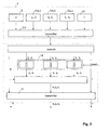
- Fig. 2 is a block diagram of the embodiment of Fig. 1.
-
- The embodiment shown in the figures comprises a
pointer 1 and acontrol unit 2 connected by acable 3. Alternatively, aradio transmitter 4 can be used for linkingpointer 1 andcontrol unit 2.Control unit 2 is provided with an interface for connecting it to acomputer 6. -
Pointer 1 is a hand-held device that can be moved around in space. It has a rod-like housing 7 with atip 8. - A
distance sensor 9 is arranged attip 8 ofpointer 1. It is adapted to detect the distance fromtip 8 to an object located in front of it and can e.g. be based on ultrasonic echo techniques. - A total of six piezoelectric
vibration gyroscope sensors pointer 1 inpoints pointer 1 is rotationally symmetric, i.e. where the rotational position of the pointer along its longitudinal axis is irrelevant, at least five sensors are required. - Suited sensors of this type are known to a person skilled in the art. In the present embodiment, sensors ENC-05EA and ENC-05EB by Murata are used. These sensors are offered in pairs of different operating frequency for avoiding interference problems. Therefore, a pair-wise arrangement of orthogonal sensors is used in the pointer of Fig. 1.
- In the present embodiment,
pointer 1 is further equipped with arechargeable battery 15 andcontrol electronics 16. Thecontrol electronics 16 collect the data from thesensors optional button 20 and transmit them throughcable 3 orradio interface 4 to controlunit 2. -
Control unit 2 is equipped with three pairs ofdouble integrators 18, each of which is calculating the second integral of one of thesensors points pointer 1, it is now possible to calculate digitisation point, i.e. the coordinates xd, yd and zd oftip 8. Optionally, the signal d ofdistance sensor 9 can be used to correct the coordinates xd, yd and zd for representing a point on the surface of the object to be measured. - The coordinates xd, yd and zd, the signal d from
distance sensor 9 and the state f ofbutton 20 are fed to atransmitter interface 21, from where they are transmitted tocomputer 6. - In a preferred application, the device of Fig. 1 is used for digitising the three-dimensional surface of an object. For this purpose,
tip 9 ofpointer 1 is brought close to the object. Wheneverdistance sensor 9 indicates that the object is close (e.g. closer than a threshold value of 1 mm), a measurement is triggered, i.e. the position oftip 8 is recorded. In this way it is possible to record individual points on the object or, iftip 9 is moved along the object, continuous (or substantially continuous) curves along the surface of the object. - The device of Figs. 1 and 2 is only one possible embodiment of the invention and it can be varied in various aspects without deviating from the present concept.
- For instance,
distance sensor 9 could be replaced by a spring-biased pin protruding fromtip 8, which, when pushed against the object, actuates a switch withinpointer 1. A contact-free detector is preferred, however. - In some applications, e.g. when using the device in a moving vehicle,
sensors control unit 2 and the reference detectors can be arranged therein as indicated under 20a, b, c. The position and/or orientation data obtained in this way can then be subtracted from the data obtained from thesensors - In the embodiment of Fig. 2, only the tip coordinates xd, yd and zd are passed along to
computer 6. However, it is also possible to pass additional data to the computer, e.g. the coordinates y1, z1, x2, y2 and x3, z3 or the direction of the longitudinal axis ofpointer 1, from whichcomputer 6 can calculate position as well as orientation of the pointer, in whichcase pointer 1 can e.g. be used as a joystick with six degrees of freedom. - The device shown here can also be used for conventional digitising purposes, such as digitising two-dimensional objects or recording of handwriting.
- In the present embodiment, piezoelectric vibration gyroscopes have been used as position sensors. It is, however, also possible to use other techniques, such as ultrasonic, radio or optical triangulation. The sensors used in the present embodiment are preferred, however, because they can be fully integrated into
pointer 1.
Claims (11)
- A three dimensional input device comprising a pointer (1) and a position detector (2, 10a, 10b, 11a, 11b, 12a, 12b) for detecting a digitisation position (xd, yd, zd) in space characterised by a proximity sensor (9) for sensing the proximity of an object to be digitised and for releasing a measurement.
- The device of claim 1 wherein said distance sensor (9) is a non-contacting distance sensor, preferably an optical or acoustical distance sensor.
- The device of one of the preceding claims wherein said pointer (1) comprises a rod-like housing (7), wherein said distance sensor (9) is arranged at an end (8) of said housing (7).
- The device of one of the preceding claims, wherein said position detector is arranged in said pointer (1).
- The device of one of the preceding claims, further comprising a reference unit (2) for defining a reference coordinate system and a reference detector (20a, 20b, 20c) for detecting the position and/or orientation of said reference unit, wherein said pointer (1) is movable in respect to said reference unit (2).
- The device of one of the preceding claims, further comprising a radio emitter (4) for transmitting data from said position detector (10a, 10b, 11a, 11b, 12a, 12b) and said distance sensor (9).
- The device of one of the preceding claims, wherein said position detector (2, 10a, 10b, 11a, llb, 12a, 12b) is adapted to measure a position and orientation of said input device and to derive said digitisation position (xd, yd, zd) therefrom.
- A method for digitising the surface of an object comprising the steps ofapproaching a tip (8) of a pointer (1) to said objectautomatically sensing a distance between said tip and said object andautomatically measuring the three dimensional position of a point (xd, yd, zd) on said object when the distance between said tip and said surface is equal to or below a given value.
- The method of claim 8 comprising the step of using said distance between said tip and said object for correcting said coordinates.
- The method of one of the claims 8 - 9, wherein said tip (1) is moved along said surface for continuously recording a curve on said surface.
- The method of one of the claims 8 - 10, comprising the step of measuring a position and orientation of said pointer (1) and of deriving said point (xd, yd, zd) therefrom.
Priority Applications (1)
| Application Number | Priority Date | Filing Date | Title |
|---|---|---|---|
| EP98112445A EP0971308A1 (en) | 1998-07-06 | 1998-07-06 | Three-dimensional input device and method for digitising objects |
Applications Claiming Priority (1)
| Application Number | Priority Date | Filing Date | Title |
|---|---|---|---|
| EP98112445A EP0971308A1 (en) | 1998-07-06 | 1998-07-06 | Three-dimensional input device and method for digitising objects |
Publications (1)
| Publication Number | Publication Date |
|---|---|
| EP0971308A1 true EP0971308A1 (en) | 2000-01-12 |
Family
ID=8232220
Family Applications (1)
| Application Number | Title | Priority Date | Filing Date |
|---|---|---|---|
| EP98112445A Withdrawn EP0971308A1 (en) | 1998-07-06 | 1998-07-06 | Three-dimensional input device and method for digitising objects |
Country Status (1)
| Country | Link |
|---|---|
| EP (1) | EP0971308A1 (en) |
Cited By (6)
| Publication number | Priority date | Publication date | Assignee | Title |
|---|---|---|---|---|
| WO2001077610A1 (en) * | 2000-04-12 | 2001-10-18 | Helios Messtechnik Gmbh & Co. Kg | Device and method for measuring objects in three dimensions |
| DE10114891A1 (en) * | 2001-03-26 | 2002-10-17 | Geometrie Concern Verwaltungs | Computer data input device has position and/or position variation measuring device for input of data by spatial movement of input device |
| WO2005037562A1 (en) * | 2003-10-17 | 2005-04-28 | Societe Bic | A liquid jet head and a liquid ejecting instrument including such a liquid jet head |
| EP2395316A1 (en) * | 2010-06-09 | 2011-12-14 | Martin Knauer | Coordinate measuring device, method for operating same and computer program product |
| WO2014142271A1 (en) * | 2013-03-14 | 2014-09-18 | シナノケンシ株式会社 | Measuring device |
| US9965051B2 (en) | 2016-06-29 | 2018-05-08 | Microsoft Technology Licensing, Llc | Input device tracking |
Citations (8)
| Publication number | Priority date | Publication date | Assignee | Title |
|---|---|---|---|---|
| DE3700139A1 (en) * | 1987-01-03 | 1988-07-14 | Friedemann Stuetz | Computer-controlled coordinate measuring device |
| US4839838A (en) * | 1987-03-30 | 1989-06-13 | Labiche Mitchell | Spatial input apparatus |
| US5128671A (en) * | 1990-04-12 | 1992-07-07 | Ltv Aerospace And Defense Company | Control device having multiple degrees of freedom |
| WO1994018663A1 (en) * | 1993-02-01 | 1994-08-18 | Wolfe, Edward, A. | Image communication apparatus |
| US5396443A (en) * | 1992-10-07 | 1995-03-07 | Hitachi, Ltd. | Information processing apparatus including arrangements for activation to and deactivation from a power-saving state |
| DE19718642A1 (en) * | 1997-05-02 | 1997-09-18 | Christian Gruen | Measuring and digitising measuring points of three dimensional objects |
| US5701140A (en) * | 1993-07-16 | 1997-12-23 | Immersion Human Interface Corp. | Method and apparatus for providing a cursor control interface with force feedback |
| EP0858015A1 (en) * | 1997-02-10 | 1998-08-12 | Mitutoyo Corporation | Measuring method and measuring instrument with a trigger probe |
-
1998
- 1998-07-06 EP EP98112445A patent/EP0971308A1/en not_active Withdrawn
Patent Citations (8)
| Publication number | Priority date | Publication date | Assignee | Title |
|---|---|---|---|---|
| DE3700139A1 (en) * | 1987-01-03 | 1988-07-14 | Friedemann Stuetz | Computer-controlled coordinate measuring device |
| US4839838A (en) * | 1987-03-30 | 1989-06-13 | Labiche Mitchell | Spatial input apparatus |
| US5128671A (en) * | 1990-04-12 | 1992-07-07 | Ltv Aerospace And Defense Company | Control device having multiple degrees of freedom |
| US5396443A (en) * | 1992-10-07 | 1995-03-07 | Hitachi, Ltd. | Information processing apparatus including arrangements for activation to and deactivation from a power-saving state |
| WO1994018663A1 (en) * | 1993-02-01 | 1994-08-18 | Wolfe, Edward, A. | Image communication apparatus |
| US5701140A (en) * | 1993-07-16 | 1997-12-23 | Immersion Human Interface Corp. | Method and apparatus for providing a cursor control interface with force feedback |
| EP0858015A1 (en) * | 1997-02-10 | 1998-08-12 | Mitutoyo Corporation | Measuring method and measuring instrument with a trigger probe |
| DE19718642A1 (en) * | 1997-05-02 | 1997-09-18 | Christian Gruen | Measuring and digitising measuring points of three dimensional objects |
Cited By (6)
| Publication number | Priority date | Publication date | Assignee | Title |
|---|---|---|---|---|
| WO2001077610A1 (en) * | 2000-04-12 | 2001-10-18 | Helios Messtechnik Gmbh & Co. Kg | Device and method for measuring objects in three dimensions |
| DE10114891A1 (en) * | 2001-03-26 | 2002-10-17 | Geometrie Concern Verwaltungs | Computer data input device has position and/or position variation measuring device for input of data by spatial movement of input device |
| WO2005037562A1 (en) * | 2003-10-17 | 2005-04-28 | Societe Bic | A liquid jet head and a liquid ejecting instrument including such a liquid jet head |
| EP2395316A1 (en) * | 2010-06-09 | 2011-12-14 | Martin Knauer | Coordinate measuring device, method for operating same and computer program product |
| WO2014142271A1 (en) * | 2013-03-14 | 2014-09-18 | シナノケンシ株式会社 | Measuring device |
| US9965051B2 (en) | 2016-06-29 | 2018-05-08 | Microsoft Technology Licensing, Llc | Input device tracking |
Similar Documents
| Publication | Publication Date | Title |
|---|---|---|
| AU743912B2 (en) | Improved pen positioning system | |
| AU2004232150B2 (en) | Buried line locator with integral position sensing | |
| RU2461849C2 (en) | Detector for detecting and determining position of concealed objects in inspected facility | |
| KR100791383B1 (en) | Method for estimating relative position between moving robot and transmitter and apparatus thereof | |
| US20060137194A1 (en) | Method and apparatus for distance measurement | |
| WO2006007306A2 (en) | Determination of orientation parameter of an elongate object with a scan beam apparatus | |
| US7774951B2 (en) | Sensing device with whisker elements | |
| JPS59195735A (en) | Apparatus for wirelessly controlling movement of object to be moved | |
| JP2006506654A (en) | Level, angle and distance measuring device | |
| EP1417675A2 (en) | Computer input device | |
| CN110785729B (en) | Electronic device for generating analog strokes and for digital storage of analog strokes and input system and method for digitizing analog recordings | |
| CN101324430A (en) | Binocular odometry based on similarity principle | |
| US8887551B2 (en) | Calibration of instrument relative to ultrasonic probe | |
| EP2015020B1 (en) | Texture measuring apparatus and method | |
| JPH09257461A (en) | Three-dimensional coordinate measuring apparatus | |
| US20010020335A1 (en) | Ergonomic, interference signal-reducing position measurement probe for mutual alignment of bodies | |
| EP0971308A1 (en) | Three-dimensional input device and method for digitising objects | |
| WO2002021154A1 (en) | Method and apparatus for three-dimensional coordinate determination | |
| KR101255024B1 (en) | Relative localization system and method using ultrasonic sensor | |
| US20220193919A1 (en) | 3d position and orientation calculation and robotic application structure using inertial measuring unit (imu) and string-encoder positions sensors | |
| JPH0875442A (en) | Simplified length measuring machine | |
| RU2537050C1 (en) | Pilot in-flight biomechanical control system | |
| JP4745675B2 (en) | Surveyor remote control device | |
| JP2650935B2 (en) | Partial discharge location method | |
| EP1067756A3 (en) | Device for determining the position of an object relative to a surface |
Legal Events
| Date | Code | Title | Description |
|---|---|---|---|
| PUAI | Public reference made under article 153(3) epc to a published international application that has entered the european phase |
Free format text: ORIGINAL CODE: 0009012 |
|
| AK | Designated contracting states |
Kind code of ref document: A1 Designated state(s): AT BE CH CY DE DK ES FI FR GB GR IE IT LI LU MC NL PT SE |
|
| AX | Request for extension of the european patent |
Free format text: AL;LT;LV;MK;RO;SI |
|
| AKX | Designation fees paid | ||
| STAA | Information on the status of an ep patent application or granted ep patent |
Free format text: STATUS: THE APPLICATION IS DEEMED TO BE WITHDRAWN |
|
| 18D | Application deemed to be withdrawn |
Effective date: 20000713 |