EP0968766B1 - Container for liquids, particularly for analysis of biological liquids - Google Patents
Container for liquids, particularly for analysis of biological liquids Download PDFInfo
- Publication number
- EP0968766B1 EP0968766B1 EP99112755A EP99112755A EP0968766B1 EP 0968766 B1 EP0968766 B1 EP 0968766B1 EP 99112755 A EP99112755 A EP 99112755A EP 99112755 A EP99112755 A EP 99112755A EP 0968766 B1 EP0968766 B1 EP 0968766B1
- Authority
- EP
- European Patent Office
- Prior art keywords
- container according
- cup
- circular
- liquids
- shaped parts
- Prior art date
- Legal status (The legal status is an assumption and is not a legal conclusion. Google has not performed a legal analysis and makes no representation as to the accuracy of the status listed.)
- Expired - Lifetime
Links
Images

Classifications
-
- B—PERFORMING OPERATIONS; TRANSPORTING
- B01—PHYSICAL OR CHEMICAL PROCESSES OR APPARATUS IN GENERAL
- B01L—CHEMICAL OR PHYSICAL LABORATORY APPARATUS FOR GENERAL USE
- B01L3/00—Containers or dishes for laboratory use, e.g. laboratory glassware; Droppers
- B01L3/50—Containers for the purpose of retaining a material to be analysed, e.g. test tubes
- B01L3/508—Containers for the purpose of retaining a material to be analysed, e.g. test tubes rigid containers not provided for above
- B01L3/5085—Containers for the purpose of retaining a material to be analysed, e.g. test tubes rigid containers not provided for above for multiple samples, e.g. microtitration plates
Definitions
- the present invention relates to a container for liquids, particularly for analysis of biological liquids.
- the container is used for example for the analyses prescribed by anti-doping tests, medical examinations for enrolment in the armed forces, or in any case in a military context, for analyses prescribed for public-sector competitive examinations, industrial medicine, etcetera.
- the containers may remain unattended and may be tampered with during such periods.
- the aim of the present invention is to eliminate the above-noted drawbacks in conventional sample containers by providing a container which simultaneously allows, in a single object, to take multiple samples and to then keep them separate.
- an object of the invention is to provide a container which allows to analyze one sample at a time without thereby contaminating the others and/or interrupting the common seal of guarantee.
- Another object of the invention is to provide a container having modest dimensions and weight which can be used easily by users.
- Another object of the invention is to provide a container which is composed of a small number of simple elements which can be manufactured with known technologies, so that it can be produced at an advantageous cost.
- a container for liquids particularly for analysis of biological liquids, comprising a main body which has a plurality of cup-shaped parts for containing said liquids, an intermediate closure element which associated with said body and is provided with tubular portions which are sealingly inserted in said cup-shaped parts, and a sealing cover which is coupled to said body.
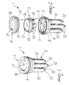
- the container generally designated by the reference numeral 1, comprises a main body 2, an intermediate closure element 3, and a sealing cover 4.
- the upper portion of the main body 2 is constituted by an open-top chamber 5 which accommodates the intermediate closure element 3.
- Said chamber 5 is formed laterally by a cylindrical wall 6 having, on its internal surface and halfway along its height a circumferential step 7 which acts as an abutment for the intermediate closure element 3, and has a split upper edge which forms a U-shaped circular groove 8 which has a circular recess 9 formed inside the groove along its outer edge, allowing to close the sealing cover 4 onto the main body 2 by pressing.
- the lower portion of the main body 2 is composed of four cup-shaped parts 10 which are connected to the chamber 5 through the bottom 11 of said chamber and protrude from it in an axial direction, ending at their lower end with a closed narrower portion 12.
- the intermediate closure element 3 comprises a circular plate 13 which has, on one face, four tubular portions 14 whose outside diameter is slightly smaller than the inside diameter of the tubular parts 10; said portions are arranged so as to fit hermetically in said parts during the coupling of the intermediate element 3 on the main body 2.
- This insertion in addition to separating the fluid in each one of the parts, produces a first mechanical conical seal.
- Said circular plate 13 has, on its outer lateral surface, a flat circular ridge 15 which abuts against the step 7, accordingly preventing any improperly performed coupling of the intermediate element 3 with the main body 2.
- the circular plate 13 On the face that lies opposite the tubular portions 14, the circular plate 13 has an additional circular ridge 16, which is required for centering the sealing cover 4 on said main body 2.
- Said sealing cover is composed of a thin and transparent circular central portion 17 which is surrounded by a thicker border 18 provided with a circular rim 19 which lies at right angles to the border 18; said rim in turn has a circular protrusion 20 which fits with a snap-together action in the recess 9 when the rim 19 is inserted in the U-shaped groove 8.
- the sealing cover 4 further comprises, on the surface that faces the circular plate 13, a circular recess 21 which is formed by the step 22 which corresponds to the region that connects the thin central portion 17 of the cover to the border 18 and a circular ridge 23 which accommodates the ridge 16.
- a label (not shown) bearing the identification data of the sample can be placed between the upper face of the element 3 and the lower face of the thin and transparent circular central portion 17 of the sealing cover 4.
- any one of the narrower portions 12 is cut and its content is sampled. If double-checks are necessary following the first test, the other narrower portions 12 are cut in succession.
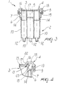
- the container has a main body, now designated by the reference numeral 102, with a cylindrical wall 106 from which loops 106a protrude in diametrically opposite positions; said loops are used to fix a forgery-preventing seal, not shown.
- the lower portion of the main body 102 is again composed of four cup-shaped parts 110 which protrude axially and end, at their lower end, with a closed narrower portion 112, which in this case has a hexagonal external profile to allow the mating of a hexagonal key, not shown.
- Said key by being turned, facilitates the separation of the narrower portion 112 in order to open the corresponding cup-shaped part 110.
Abstract
Description
- The present invention relates to a container for liquids, particularly for analysis of biological liquids.
- The container is used for example for the analyses prescribed by anti-doping tests, medical examinations for enrolment in the armed forces, or in any case in a military context, for analyses prescribed for public-sector competitive examinations, industrial medicine, etcetera.
- The problem of ensuring serious, accurate and reliable anti-doping tests for athletes has always been strongly felt.
- Biological liquids are currently sampled after a competition by means of ordinary plastic containers which are then sealed and marked under the supervision of competition directors so as to ensure that sampling has been performed correctly.
- Moreover, it is common practice to collect multiple samples in separate containers in order to allow, if necessary, to perform subsequent double-checking tests.
- Regrettably, this system lends itself to easy forgery.
- First of all, during the fast-paced events that follow a competition the containers might be swapped, even only due to error on the part of the assigned personnel.
- Moreover, the containers may remain unattended and may be tampered with during such periods.
- In addition to all this, the biological characteristics of the liquids collected in separate containers are not uniform and therefore the different samples can bias the results of the analyses.
- The aim of the present invention is to eliminate the above-noted drawbacks in conventional sample containers by providing a container which simultaneously allows, in a single object, to take multiple samples and to then keep them separate.
- Within the scope of this aim, an object of the invention is to provide a container which allows to analyze one sample at a time without thereby contaminating the others and/or interrupting the common seal of guarantee.
- Another object of the invention is to provide a container having modest dimensions and weight which can be used easily by users.
- Another object of the invention is to provide a container which is composed of a small number of simple elements which can be manufactured with known technologies, so that it can be produced at an advantageous cost.
- This aim, these objects and others which will become apparent hereinafter are achieved by a container for liquids, particularly for analysis of biological liquids, comprising a main body which has a plurality of cup-shaped parts for containing said liquids, an intermediate closure element which associated with said body and is provided with tubular portions which are sealingly inserted in said cup-shaped parts, and a sealing cover which is coupled to said body.
- Further characteristics and advantages of the present invention will become apparent from the following detailed description of a preferred but not exclusive embodiment of the container for liquids, particularly for analyzing biological liquids, illustrated only by way of non-limitative example in the accompanying drawings, wherein:
- Figure 1 is an axonometric view of the container according to the invention;
- Figure 2 is an exploded view of the container according to the invention;
- Figure 3 is a sectional view, taken along a central plane, of the container according to the invention;
- Figure 4 is a sectional view of a detail of the container;
- Figure 5 is a perspective view of a further constructive embodiment of the container according to the invention.
-
- With reference to the above Figures 1 to 4, the container, generally designated by the reference numeral 1, comprises a
main body 2, anintermediate closure element 3, and asealing cover 4. - The upper portion of the
main body 2 is constituted by an open-top chamber 5 which accommodates theintermediate closure element 3. - Said
chamber 5 is formed laterally by acylindrical wall 6 having, on its internal surface and halfway along its height acircumferential step 7 which acts as an abutment for theintermediate closure element 3, and has a split upper edge which forms a U-shapedcircular groove 8 which has a circular recess 9 formed inside the groove along its outer edge, allowing to close thesealing cover 4 onto themain body 2 by pressing. - The lower portion of the
main body 2 is composed of four cup-shaped parts 10 which are connected to thechamber 5 through the bottom 11 of said chamber and protrude from it in an axial direction, ending at their lower end with a closednarrower portion 12. - The
intermediate closure element 3 comprises acircular plate 13 which has, on one face, fourtubular portions 14 whose outside diameter is slightly smaller than the inside diameter of thetubular parts 10; said portions are arranged so as to fit hermetically in said parts during the coupling of theintermediate element 3 on themain body 2. - This insertion, in addition to separating the fluid in each one of the parts, produces a first mechanical conical seal.
- Said
circular plate 13 has, on its outer lateral surface, a flatcircular ridge 15 which abuts against thestep 7, accordingly preventing any improperly performed coupling of theintermediate element 3 with themain body 2. - On the face that lies opposite the
tubular portions 14, thecircular plate 13 has an additionalcircular ridge 16, which is required for centering thesealing cover 4 on saidmain body 2. - Said sealing cover is composed of a thin and transparent circular
central portion 17 which is surrounded by athicker border 18 provided with acircular rim 19 which lies at right angles to theborder 18; said rim in turn has acircular protrusion 20 which fits with a snap-together action in the recess 9 when therim 19 is inserted in theU-shaped groove 8. - This insertion produces a second seal which prevents the leakage of any liquid present in the central pocket and in the lateral pockets that lie between the
tubular portions 14. - The
sealing cover 4 further comprises, on the surface that faces thecircular plate 13, acircular recess 21 which is formed by thestep 22 which corresponds to the region that connects the thincentral portion 17 of the cover to theborder 18 and acircular ridge 23 which accommodates theridge 16. - Conveniently, a label (not shown) bearing the identification data of the sample can be placed between the upper face of the
element 3 and the lower face of the thin and transparent circularcentral portion 17 of thesealing cover 4. - Operation, with reference to the above figures, is as follows:
- the liquid is introduced in the
main body 2; a first closure is performed by coupling theintermediate body 3 to themain body 2 and then the final seal is provided by locking thecover 4 on saidbody 2. Thetubular portions 14, in addition to closing the cup-shaped parts 10, also have the purpose of increasing the volume inside each part so as to avoid any overflow of the contained liquid during the closing operation. - During testing, any one of the
narrower portions 12 is cut and its content is sampled. If double-checks are necessary following the first test, the othernarrower portions 12 are cut in succession. - In practice it has been observed that the invention achieves the intended aim and objects, since said container prevents all forgery and is preset for multiple separate tests of the sampled liquid which cannot be contaminated.
- The invention is also susceptible of numerous modifications and variations, all of which are within the scope of the inventive concept.
- Accordingly, with particular reference to the above cited Figure 5, in a further constructive embodiment the container has a main body, now designated by the
reference numeral 102, with acylindrical wall 106 from whichloops 106a protrude in diametrically opposite positions; said loops are used to fix a forgery-preventing seal, not shown. - The lower portion of the
main body 102 is again composed of four cup-shaped parts 110 which protrude axially and end, at their lower end, with a closednarrower portion 112, which in this case has a hexagonal external profile to allow the mating of a hexagonal key, not shown. - Said key, by being turned, facilitates the separation of the
narrower portion 112 in order to open the corresponding cup-shaped part 110. - The materials employed, as well as the contingent shapes and dimensions, may of course be any according to the requirements and the state of the art.
- Where technical features mentioned in any claim are followed by reference signs, those reference signs have been included for the sole purpose of increasing the intelligibility of the claims and accordingly, such reference signs do not have any limiting effect on the interpretation of each element identified by way of example by such reference signs.
Claims (13)
- A container for liquids, particularly for analysis of biological liquids, comprising a main body (2;102) which has a plurality of cup-shaped parts (10;110) for containing said liquids, an intermediate closure element (3) is associated with said body (2;102) and is provided with tubular portions (14) which are sealingly inserted in said cup-shaped parts (10;110), and a sealing cover (4) which can be coupled to said body (2;102).
- The container according to claim 1, characterized in that said main body (2;102) comprises an open-top chamber (5) which is formed laterally by a cylindrical wall (6;106) for accommodating said intermediate closure element (3) and is connected to said cup-shaped parts (10;110) through holes formed in the bottom (11).
- The container according to claim 2, characterized in that said cylindrical wall (6) of said chamber (5) comprises, along its internal surface, a circumferential abutment step (7) and an upper edge which is split so as to form a circumferential U-shaped groove (8).
- The container according to claim 3, characterized in that said U-shaped groove (8) comprises a recess (9) formed along its outer edge.
- The container according to claims 1 and 2, characterized in that said cup-shaped parts (10;110) protrude from said bottom (11) in an axial direction and end with a closed narrower portion (12;112).
- The container according to claim 3, characterized in that said intermediate closure element (3) comprises a circular plate (13) which bears said tubular portions (14) on one of its sides and has, on its other side, a circular ridge (16) for centering the sealing cover (4), said plate (13) having, on its lateral surface, a flat circular ridge (15) which abuts against said abutment step (7).
- The container according to claim 6, characterized in that the insertion of said tubular portions (14) in said cup-shaped parts provides a first liquid-tight seal.
- The container according to claims 1 or 4, characterized in that said sealing cover (4) comprises a transparent circular central portion (17) and a border (18) which surrounds it together with a circular rim (19) which is arranged at right angles to said border (18) and engages said U-shaped groove (8).
- The container according to claim 8 when depending on claim 4, characterized in that said sealing cover (4) comprises a circular protrusion (20) at the end of said rim (19) which is directed toward the outside of said cover (4) and fits with a snap-fitting action in said recess (9) of said U-shaped groove (8).
- The container according to claim 9, characterized in that said snap-fitting produces a second liquid-tight seal.
- The container according to one or more of the preceding claims, characterized in that said sealing cover (4) comprises, on the surface that faces said circular plate (13), a circumferential recess (21) between the step (22) formed at the region that connects the central portion (17) and the border (18) and a circular ridge (23) for accommodating said ridge (16) of said circular plate (13).
- The container according to one or more of the preceding claims, characterized in that loops (106a) protrude in diametrically opposite positions of said cylindrical wall (106) of said main body (102) and are meant to fix a forgery-preventing seal thereto.
- The container according to one or more of the preceding claims, characterized in that each one of said four cup-shaped parts (110) that protrude axially from said main body ends, at its lower end, with a closed narrower portion (112) whose external profile is hexagonal in order to allow the mating of a hexagonal key.
Applications Claiming Priority (2)
| Application Number | Priority Date | Filing Date | Title |
|---|---|---|---|
| IT98PD000166A ITPD980166A1 (en) | 1998-07-02 | 1998-07-02 | CONTAINER OF LIQUIDS PARTICULARLY FOR ANALYSIS OF BIOLOGICAL LIQUIDS. |
| ITPD980166 | 1998-07-02 |
Publications (3)
| Publication Number | Publication Date |
|---|---|
| EP0968766A2 EP0968766A2 (en) | 2000-01-05 |
| EP0968766A3 EP0968766A3 (en) | 2000-09-13 |
| EP0968766B1 true EP0968766B1 (en) | 2004-09-22 |
Family
ID=11392268
Family Applications (1)
| Application Number | Title | Priority Date | Filing Date |
|---|---|---|---|
| EP99112755A Expired - Lifetime EP0968766B1 (en) | 1998-07-02 | 1999-07-01 | Container for liquids, particularly for analysis of biological liquids |
Country Status (6)
| Country | Link |
|---|---|
| US (1) | US6517780B1 (en) |
| EP (1) | EP0968766B1 (en) |
| AT (1) | ATE276829T1 (en) |
| DE (1) | DE69920331T2 (en) |
| ES (1) | ES2229589T3 (en) |
| IT (1) | ITPD980166A1 (en) |
Cited By (2)
| Publication number | Priority date | Publication date | Assignee | Title |
|---|---|---|---|---|
| US9513303B2 (en) | 2013-03-15 | 2016-12-06 | Abbott Laboratories | Light-blocking system for a diagnostic analyzer |
| US9993820B2 (en) | 2013-03-15 | 2018-06-12 | Abbott Laboratories | Automated reagent manager of a diagnostic analyzer system |
Families Citing this family (16)
| Publication number | Priority date | Publication date | Assignee | Title |
|---|---|---|---|---|
| US20050042145A1 (en) * | 2003-08-22 | 2005-02-24 | Sysmex Corporation | Container for analyzer, detection container, reaction container and packing container for storing detection container |
| US7458942B2 (en) * | 2004-09-22 | 2008-12-02 | Medtox | Systems and methods for collecting, testing and transporting liquid biological specimens |
| US20110095034A1 (en) * | 2005-10-17 | 2011-04-28 | Skala Theodore P | Thin-walled cup |
| US7845512B2 (en) * | 2005-10-17 | 2010-12-07 | Theodore P Skala | Thin-walled cup |
| CN101382510B (en) * | 2007-09-06 | 2012-07-25 | 清华大学 | Multi-bottle detecting container |
| ITPD20080338A1 (en) | 2008-11-19 | 2010-05-20 | Kaltek S R L | DEVICE FOR THE REALIZATION OF QUICK "ON-SITE" TESTS ON BIOLOGICAL LIQUIDS |
| WO2011110469A1 (en) | 2010-03-11 | 2011-09-15 | Lp Italiana S.P.A. | Container for a physiological liquid |
| ITMI20111396A1 (en) * | 2011-07-26 | 2013-01-27 | Idea Plast S R L | LIQUID CONTAINER FOR CHEMICAL ANALYSIS |
| CN105121294B (en) * | 2013-03-13 | 2018-09-04 | 雅培实验室 | Keying lid for container and relative device and system |
| WO2014144759A1 (en) | 2013-03-15 | 2014-09-18 | Abbott Laboratories | Linear track diagnostic analyzer |
| USD869276S1 (en) | 2013-12-20 | 2019-12-10 | Abbott Laboratories | Bottle cap |
| USD886609S1 (en) | 2013-12-20 | 2020-06-09 | Abbott Laboratories | Bottle cap |
| USD881708S1 (en) | 2013-12-20 | 2020-04-21 | Abbott Laboratories | Bottle with cap |
| USD881709S1 (en) | 2013-12-20 | 2020-04-21 | Abbott Laboratories | Bottle with cap |
| EP3974843A1 (en) * | 2015-05-01 | 2022-03-30 | Abbott Laboratories | Apparatus for removing liquid contents of a container |
| IT201800007364A1 (en) * | 2018-07-20 | 2020-01-20 | LIQUID CONTAINER, PARTICULARLY FOR ANALYSIS OF BIOLOGICAL LIQUIDS |
Family Cites Families (15)
| Publication number | Priority date | Publication date | Assignee | Title |
|---|---|---|---|---|
| US4073693A (en) | 1976-06-08 | 1978-02-14 | American Home Products Corporation | Apparatus and method for conducting a plurality of biological tests |
| US4042337A (en) | 1977-02-17 | 1977-08-16 | Griffith Donald P | Urine collection device |
| US4385115A (en) | 1980-10-22 | 1983-05-24 | Hoffmann-La Roche Inc. | Diagnostics testing devices and processes |
| US5817510A (en) * | 1995-02-24 | 1998-10-06 | Xechem International, Inc. | Device and method for evaluating microorganisms |
| US5680968A (en) * | 1995-05-03 | 1997-10-28 | Phoenix Closures, Inc. | Container closure system |
| US5681740A (en) * | 1995-06-05 | 1997-10-28 | Cytotherapeutics, Inc. | Apparatus and method for storage and transporation of bioartificial organs |
| US5976895A (en) * | 1996-03-11 | 1999-11-02 | American Biomedica Corporation | Device for the collection, testing and shipment of body fluid samples |
| US6027694A (en) * | 1996-10-17 | 2000-02-22 | Texperts, Inc. | Spillproof microplate assembly |
| US5837139A (en) * | 1997-04-14 | 1998-11-17 | Lerch; Andrea M. | Fluid collecting and dividing apparatus |
| US5997820A (en) | 1997-05-19 | 1999-12-07 | Johnson & Johnson Clinical Diagnostics, Inc. | Integrally attached and operable multiple reaction vessels |
| US5897840A (en) * | 1997-07-16 | 1999-04-27 | Battelle Memorial Institute | Multi-chambered urine specimen container for automatic extraction and high forensic integrity |
| US6096562A (en) * | 1997-10-27 | 2000-08-01 | Nalge Nunc International Corporation | Multi-slide assembly including slide, frame and strip cap, and methods thereof |
| US6106783A (en) * | 1998-06-30 | 2000-08-22 | Microliter Analytical Supplies, Inc. | Microplate assembly and closure |
| US6361746B1 (en) * | 1998-11-16 | 2002-03-26 | Julie Ann Wlodarski | Medical specimen tote |
| US6444174B1 (en) * | 2000-01-24 | 2002-09-03 | Laboratoire Soludia | Cartridge for the preparation of a solution for medical use |
-
1998
- 1998-07-02 IT IT98PD000166A patent/ITPD980166A1/en unknown
-
1999
- 1999-06-23 US US09/338,492 patent/US6517780B1/en not_active Expired - Lifetime
- 1999-07-01 ES ES99112755T patent/ES2229589T3/en not_active Expired - Lifetime
- 1999-07-01 AT AT99112755T patent/ATE276829T1/en not_active IP Right Cessation
- 1999-07-01 DE DE69920331T patent/DE69920331T2/en not_active Expired - Lifetime
- 1999-07-01 EP EP99112755A patent/EP0968766B1/en not_active Expired - Lifetime
Cited By (3)
| Publication number | Priority date | Publication date | Assignee | Title |
|---|---|---|---|---|
| US9513303B2 (en) | 2013-03-15 | 2016-12-06 | Abbott Laboratories | Light-blocking system for a diagnostic analyzer |
| US9993820B2 (en) | 2013-03-15 | 2018-06-12 | Abbott Laboratories | Automated reagent manager of a diagnostic analyzer system |
| US10330691B2 (en) | 2013-03-15 | 2019-06-25 | Abbott Laboratories | Light-blocking system for a diagnostic analyzer |
Also Published As
| Publication number | Publication date |
|---|---|
| ES2229589T3 (en) | 2005-04-16 |
| US6517780B1 (en) | 2003-02-11 |
| DE69920331T2 (en) | 2005-02-17 |
| ITPD980166A1 (en) | 2000-01-02 |
| ATE276829T1 (en) | 2004-10-15 |
| EP0968766A3 (en) | 2000-09-13 |
| EP0968766A2 (en) | 2000-01-05 |
| DE69920331D1 (en) | 2004-10-28 |
Similar Documents
| Publication | Publication Date | Title |
|---|---|---|
| EP0968766B1 (en) | Container for liquids, particularly for analysis of biological liquids | |
| US7470404B2 (en) | Fluid sample collection and isolation cup | |
| US6669908B2 (en) | Urine test device | |
| CA2434604C (en) | Cartridge for containing a specimen sample for optical analysis | |
| US7517495B2 (en) | Biological specimen collection and analysis system | |
| US5429804A (en) | One-step testing device | |
| US5501837A (en) | One-step test device | |
| US20090024055A1 (en) | All-in-one biological specimen collecting, transporting and analyzing device | |
| EP0668745B1 (en) | Assaying device | |
| EP0329120B1 (en) | Luminescence test and exposure apparatus | |
| JP2940618B2 (en) | Ball and socket lid for sample collection containers incorporating integrated flexible seal | |
| JP3052287B2 (en) | Ball and socket lid for sample collection container incorporating dimple lock mechanism | |
| JP3019213B2 (en) | Ball and socket lid for sample collection container | |
| US7927560B2 (en) | Specimen cup system for sample testing and secure retention | |
| JPH11171217A (en) | Ball and socket lid for sample collection container incorporating elastic elastomer seal | |
| JPH11148937A (en) | Ball and socket lid for sample collection container having integrated diaphragm | |
| EP3162727B1 (en) | Closure device for coupling containers | |
| US20080240986A1 (en) | Assaying device for collecting, storing, and testing fluid samples | |
| EP0225922A1 (en) | Analytical container | |
| US20240033730A1 (en) | Pcr detection chip, associated test device and implementation analysis system | |
| WO2022223121A1 (en) | Swab tube | |
| IT201800007364A1 (en) | LIQUID CONTAINER, PARTICULARLY FOR ANALYSIS OF BIOLOGICAL LIQUIDS |
Legal Events
| Date | Code | Title | Description |
|---|---|---|---|
| PUAI | Public reference made under article 153(3) epc to a published international application that has entered the european phase |
Free format text: ORIGINAL CODE: 0009012 |
|
| AK | Designated contracting states |
Kind code of ref document: A2 Designated state(s): AT BE CH CY DE DK ES FI FR GB GR IE IT LI LU MC NL PT SE |
|
| AX | Request for extension of the european patent |
Free format text: AL;LT;LV;MK;RO;SI |
|
| PUAL | Search report despatched |
Free format text: ORIGINAL CODE: 0009013 |
|
| AK | Designated contracting states |
Kind code of ref document: A3 Designated state(s): AT BE CH CY DE DK ES FI FR GB GR IE IT LI LU MC NL PT SE |
|
| AX | Request for extension of the european patent |
Free format text: AL;LT;LV;MK;RO;SI |
|
| 17P | Request for examination filed |
Effective date: 20010226 |
|
| AKX | Designation fees paid |
Free format text: AT BE CH CY DE DK ES FI FR GB GR IE IT LI LU MC NL PT SE |
|
| GRAP | Despatch of communication of intention to grant a patent |
Free format text: ORIGINAL CODE: EPIDOSNIGR1 |
|
| GRAS | Grant fee paid |
Free format text: ORIGINAL CODE: EPIDOSNIGR3 |
|
| GRAA | (expected) grant |
Free format text: ORIGINAL CODE: 0009210 |
|
| AK | Designated contracting states |
Kind code of ref document: B1 Designated state(s): AT BE CH CY DE DK ES FI FR GB GR IE IT LI LU MC NL PT SE |
|
| PG25 | Lapsed in a contracting state [announced via postgrant information from national office to epo] |
Ref country code: NL Free format text: LAPSE BECAUSE OF FAILURE TO SUBMIT A TRANSLATION OF THE DESCRIPTION OR TO PAY THE FEE WITHIN THE PRESCRIBED TIME-LIMIT Effective date: 20040922 Ref country code: FI Free format text: LAPSE BECAUSE OF FAILURE TO SUBMIT A TRANSLATION OF THE DESCRIPTION OR TO PAY THE FEE WITHIN THE PRESCRIBED TIME-LIMIT Effective date: 20040922 Ref country code: BE Free format text: LAPSE BECAUSE OF FAILURE TO SUBMIT A TRANSLATION OF THE DESCRIPTION OR TO PAY THE FEE WITHIN THE PRESCRIBED TIME-LIMIT Effective date: 20040922 Ref country code: AT Free format text: LAPSE BECAUSE OF FAILURE TO SUBMIT A TRANSLATION OF THE DESCRIPTION OR TO PAY THE FEE WITHIN THE PRESCRIBED TIME-LIMIT Effective date: 20040922 |
|
| REG | Reference to a national code |
Ref country code: GB Ref legal event code: FG4D |
|
| REG | Reference to a national code |
Ref country code: CH Ref legal event code: EP |
|
| REG | Reference to a national code |
Ref country code: IE Ref legal event code: FG4D |
|
| REF | Corresponds to: |
Ref document number: 69920331 Country of ref document: DE Date of ref document: 20041028 Kind code of ref document: P |
|
| REG | Reference to a national code |
Ref country code: CH Ref legal event code: NV Representative=s name: AXON PATENT GMBH |
|
| PG25 | Lapsed in a contracting state [announced via postgrant information from national office to epo] |
Ref country code: SE Free format text: LAPSE BECAUSE OF FAILURE TO SUBMIT A TRANSLATION OF THE DESCRIPTION OR TO PAY THE FEE WITHIN THE PRESCRIBED TIME-LIMIT Effective date: 20041222 Ref country code: DK Free format text: LAPSE BECAUSE OF FAILURE TO SUBMIT A TRANSLATION OF THE DESCRIPTION OR TO PAY THE FEE WITHIN THE PRESCRIBED TIME-LIMIT Effective date: 20041222 |
|
| REG | Reference to a national code |
Ref country code: GR Ref legal event code: EP Ref document number: 20040404124 Country of ref document: GR |
|
| NLV1 | Nl: lapsed or annulled due to failure to fulfill the requirements of art. 29p and 29m of the patents act | ||
| REG | Reference to a national code |
Ref country code: ES Ref legal event code: FG2A Ref document number: 2229589 Country of ref document: ES Kind code of ref document: T3 |
|
| PG25 | Lapsed in a contracting state [announced via postgrant information from national office to epo] |
Ref country code: LU Free format text: LAPSE BECAUSE OF NON-PAYMENT OF DUE FEES Effective date: 20050701 Ref country code: IE Free format text: LAPSE BECAUSE OF NON-PAYMENT OF DUE FEES Effective date: 20050701 Ref country code: CY Free format text: LAPSE BECAUSE OF FAILURE TO SUBMIT A TRANSLATION OF THE DESCRIPTION OR TO PAY THE FEE WITHIN THE PRESCRIBED TIME-LIMIT Effective date: 20050701 |
|
| PLBE | No opposition filed within time limit |
Free format text: ORIGINAL CODE: 0009261 |
|
| STAA | Information on the status of an ep patent application or granted ep patent |
Free format text: STATUS: NO OPPOSITION FILED WITHIN TIME LIMIT |
|
| PG25 | Lapsed in a contracting state [announced via postgrant information from national office to epo] |
Ref country code: MC Free format text: LAPSE BECAUSE OF NON-PAYMENT OF DUE FEES Effective date: 20050731 |
|
| ET | Fr: translation filed | ||
| 26N | No opposition filed |
Effective date: 20050623 |
|
| REG | Reference to a national code |
Ref country code: IE Ref legal event code: MM4A |
|
| PG25 | Lapsed in a contracting state [announced via postgrant information from national office to epo] |
Ref country code: PT Free format text: LAPSE BECAUSE OF NON-PAYMENT OF DUE FEES Effective date: 20050222 |
|
| REG | Reference to a national code |
Ref country code: FR Ref legal event code: PLFP Year of fee payment: 18 |
|
| REG | Reference to a national code |
Ref country code: FR Ref legal event code: PLFP Year of fee payment: 19 |
|
| REG | Reference to a national code |
Ref country code: FR Ref legal event code: PLFP Year of fee payment: 20 |
|
| PGFP | Annual fee paid to national office [announced via postgrant information from national office to epo] |
Ref country code: IT Payment date: 20180521 Year of fee payment: 20 |
|
| PGFP | Annual fee paid to national office [announced via postgrant information from national office to epo] |
Ref country code: FR Payment date: 20180719 Year of fee payment: 20 Ref country code: DE Payment date: 20180723 Year of fee payment: 20 Ref country code: ES Payment date: 20180802 Year of fee payment: 20 |
|
| PGFP | Annual fee paid to national office [announced via postgrant information from national office to epo] |
Ref country code: GB Payment date: 20180719 Year of fee payment: 20 Ref country code: GR Payment date: 20180723 Year of fee payment: 20 Ref country code: CH Payment date: 20180724 Year of fee payment: 20 |
|
| REG | Reference to a national code |
Ref country code: DE Ref legal event code: R071 Ref document number: 69920331 Country of ref document: DE |
|
| REG | Reference to a national code |
Ref country code: CH Ref legal event code: PL |
|
| REG | Reference to a national code |
Ref country code: GB Ref legal event code: PE20 Expiry date: 20190630 |
|
| PG25 | Lapsed in a contracting state [announced via postgrant information from national office to epo] |
Ref country code: GB Free format text: LAPSE BECAUSE OF EXPIRATION OF PROTECTION Effective date: 20190630 |
|
| REG | Reference to a national code |
Ref country code: ES Ref legal event code: FD2A Effective date: 20200724 |
|
| PG25 | Lapsed in a contracting state [announced via postgrant information from national office to epo] |
Ref country code: ES Free format text: LAPSE BECAUSE OF EXPIRATION OF PROTECTION Effective date: 20190702 |