EP0966984A2 - Connector element - Google Patents
Connector element Download PDFInfo
- Publication number
- EP0966984A2 EP0966984A2 EP99111745A EP99111745A EP0966984A2 EP 0966984 A2 EP0966984 A2 EP 0966984A2 EP 99111745 A EP99111745 A EP 99111745A EP 99111745 A EP99111745 A EP 99111745A EP 0966984 A2 EP0966984 A2 EP 0966984A2
- Authority
- EP
- European Patent Office
- Prior art keywords
- connector element
- pipe socket
- connector
- shut
- piercing body
- Prior art date
- Legal status (The legal status is an assumption and is not a legal conclusion. Google has not performed a legal analysis and makes no representation as to the accuracy of the status listed.)
- Granted
Links
Images


Classifications
-
- A—HUMAN NECESSITIES
- A61—MEDICAL OR VETERINARY SCIENCE; HYGIENE
- A61M—DEVICES FOR INTRODUCING MEDIA INTO, OR ONTO, THE BODY; DEVICES FOR TRANSDUCING BODY MEDIA OR FOR TAKING MEDIA FROM THE BODY; DEVICES FOR PRODUCING OR ENDING SLEEP OR STUPOR
- A61M39/00—Tubes, tube connectors, tube couplings, valves, access sites or the like, specially adapted for medical use
- A61M39/10—Tube connectors; Tube couplings
- A61M39/14—Tube connectors; Tube couplings for connecting tubes having sealed ends
-
- A—HUMAN NECESSITIES
- A61—MEDICAL OR VETERINARY SCIENCE; HYGIENE
- A61M—DEVICES FOR INTRODUCING MEDIA INTO, OR ONTO, THE BODY; DEVICES FOR TRANSDUCING BODY MEDIA OR FOR TAKING MEDIA FROM THE BODY; DEVICES FOR PRODUCING OR ENDING SLEEP OR STUPOR
- A61M39/00—Tubes, tube connectors, tube couplings, valves, access sites or the like, specially adapted for medical use
- A61M39/10—Tube connectors; Tube couplings
- A61M2039/1027—Quick-acting type connectors
-
- A—HUMAN NECESSITIES
- A61—MEDICAL OR VETERINARY SCIENCE; HYGIENE
- A61M—DEVICES FOR INTRODUCING MEDIA INTO, OR ONTO, THE BODY; DEVICES FOR TRANSDUCING BODY MEDIA OR FOR TAKING MEDIA FROM THE BODY; DEVICES FOR PRODUCING OR ENDING SLEEP OR STUPOR
- A61M39/00—Tubes, tube connectors, tube couplings, valves, access sites or the like, specially adapted for medical use
- A61M39/10—Tube connectors; Tube couplings
- A61M2039/1061—Break-apart tubing connectors or couplings
-
- Y—GENERAL TAGGING OF NEW TECHNOLOGICAL DEVELOPMENTS; GENERAL TAGGING OF CROSS-SECTIONAL TECHNOLOGIES SPANNING OVER SEVERAL SECTIONS OF THE IPC; TECHNICAL SUBJECTS COVERED BY FORMER USPC CROSS-REFERENCE ART COLLECTIONS [XRACs] AND DIGESTS
- Y10—TECHNICAL SUBJECTS COVERED BY FORMER USPC
- Y10S—TECHNICAL SUBJECTS COVERED BY FORMER USPC CROSS-REFERENCE ART COLLECTIONS [XRACs] AND DIGESTS
- Y10S604/00—Surgery
- Y10S604/905—Aseptic connectors or couplings, e.g. frangible, piercable
Definitions
- the present invention relates to a connector element, in particular for connection of tubes, cannulas and catheters with an area for guiding a flowing medium, with a shut-off element through which the area to Guide of the medium is closable and with an area for receiving a piercing body, which is designed such that the piercing body is relative is movable to the shut-off element and the shut-off element during connection is opened by the piercing body.
- connectors An important area of use for connectors is the connection of a container via a hose line with medical equipment, for example with a dialyzer, or the connection of two hose ends to the Purposes of providing extension leads. To always be sterile and ensure a tight connection and thus a risk to patients exclude high demands on the execution and quality of the Connectors as well as the type of connection of the connectors, causing contamination not only before, but also during and after Connection should be prevented.
- WO 82/02528 describes a connector system made up of two connector elements disclosed, in which the connector elements prior to the connection by means of thermoplastic membranes are closed.
- the connector elements are on their end facing away from the thermoplastic membrane in each case with a Connected hose, which in turn, for example, with a container for receiving of dialysis fluids or in connection with a dialysis machine.
- the connector elements point to the opening in the hoses Hose membranes on a tapered end.
- the opening of the Hose membranes by means of the pointed ends of the connector elements, the Movement of the pointed ends relative to the hose membranes through a bellows executed area of the hose is made possible.
- the connector provides a complex system made up of different membranes and connector elements on what the manufacture of the connectors is correspondingly complex and expensive designed.
- WO 94/08173 describes a connector system with two connector elements, which are each closed by membranes. After merging the A displaceable dome is guided through the membranes in a membrane the connector elements is movably arranged. In the unconnected state the dome is recorded in a room by one of the membranes is limited. Accordingly, it is necessary to manufacture the membrane after inserting the mandrel to fix later on the connector element, which the Manufacturing process of the connector designed relatively expensive.
- a generic connector element which has a puncture body which is relative to one as an elastomeric membrane executed shut-off element is movable and opens this at the connection.
- the piercing body has a male Luer cone on its opening side which cooperates with a corresponding female cone during the connection.
- the elastomeric membrane extends over the area for guiding one flowing medium and closes it in the disconnected state.
- the membrane lies against a step of the connector element and is there pressed by means of a fitting. It is such a connector element disadvantage that this is made up of several different materials and that the membrane is inserted later and fixed liquid-tight got to.
- This task is based on a generic connector element solved in that the shut-off element as a monomaterial component of the connector element is executed.
- This makes it relatively easy to manufacture the connector elements allows because the shut-off element is an integral part of the connector element and a subsequent positioning and Fixation is not necessary.
- Subsequent application of membranes is thus not mandatory. This not only simplifies the manufacture of the connectors, but because of the possibility of the connector elements and shut-off elements Manufacturing in one step also becomes a particularly dense arrangement reached. Subsequent welding, for example of film membranes or the subsequent welding or arrangement of membrane-populated Individual components and a correspondingly complex inspection can accordingly eliminated.
- the shut-off element is designed as an injection molded membrane.
- the injection molding membrane can same operation can be made with the connector element, creating a subsequent application of shut-off elements of any shape becomes unnecessary.
- the area to guide the medium includes
- the area for guiding the medium is one Pipe socket includes.
- the Connector element has a housing and the pipe socket in the housing is recorded.
- the pipe socket through the shut-off element For example, a membrane, be closed, which results in tightness and sterility of the connected hoses or containers is ensured.
- the piercing body is arranged in the pipe socket.
- the arrangement is such that a Cutting or opening the shut-off element through the piercing body he follows.
- the housing can serve the pipe socket as well as the shut-off element against unwanted touching and introduction of contaminants protect.
- the housing diameter can be designed such that a accidental contact with the pipe socket or the areas after the connection with liquid or gas, is not possible.
- the locking device can run around the outer circumference of the piercing body Groove and a projection extending on the inner circumference of the pipe socket include. During or after the manufacture or before using the connector the piercing body can be inserted into the pipe socket accordingly and are held in the desired position by the lock.
- the piercing body is designed such that this through a pipe socket a further connector element to be connected to the connector element is detachable from the lock. This ensures that only during the Connection of the piercing body is released from its locking and by means of a Pipe socket is moved such that the severing or opening of the Shut-off element takes place.
- the lock is advantageously designed such that the shut-off element of one of the connector elements is first cut before the corresponding pipe socket releases the puncture body from the detent and then the second shut-off element or the second membrane is severed.
- the piercing body can be released from the locking device in that this has a projection arranged on the outer circumference, which with the Pipe socket of a further connector element to be connected to the connector element is connectable.
- the housing and the Pipe socket of a further connector element to be connected to the connector element are at least partially recordable. This is done by an appropriate Design of the inner or outer diameter of the adjacent Components reached.
- the pipe socket is beveled in its end region is. This will push one of the pipe sockets into this receiving pipe socket facilitates, advantageously expanding the receiving Pipe socket takes place, which is a particularly tight connection between the two Ensures pipe socket.
- the connection and, if necessary, the disconnection can be done by machine or by hand. It is advantageous if the deconnection is connected with a higher power requirement due to the design than the connector. If necessary, constructive elements, for example injection molding, integrate that make disconnection impossible.
- the piercing body is essentially cylindrical Form and pointed at its ends. This makes it proportional simple and low-force opening of the shut-off elements or Enables membranes. It is also possible to notch the puncture body or perforated or in a star profile shape.
- the Connector element and the piercing body are designed as injection molded parts.
- the production can be carried out inexpensively in multiple injection molds. This enables the parts to be easily manufactured in many different ways Embodiments.
- this Housing and the pipe socket of the connector element cylindrical outer and Inner surfaces on this has the advantage that neither in the manufacture nor in the Application of the connector system rotary positions are required. Much more can the connection by simply inserting one of the connector element into the other connector element. With an appropriate design the housing of the connector elements can be achieved that a special good protection against contact results. Typical values for the inside diameter of the housing are 8.6 mm for the female connector and 7.4 mm for the male connector, which is good protection against accidental contact also against the penetration thinner Guaranteed fingertips.
- the end of the pipe socket can be on the inside or outside surface have circumferential projection, by means of which a sealing connection with an inserted or receiving pipe socket of another connector element can be produced.
- This also has the advantage that a seal relative to the ambient atmosphere before it pierces the shut-off elements or the membranes comes. Endanger accordingly also high and low pressures between the liquid and gas-filled zones of the connector elements relative to the environment and pressure differences between the connector elements, depending on the dimensioning of the arrangement up to several Bar amount, not sterility and tightness before, during and after of the connection, since there is always a tight connection between those to be connected Connector elements is produced, and only in the next step the sealing membranes be pierced.
- the shut-off element and the area for receiving the piercing body are arranged in this way are that the piercing body from the connector side of the connector element can be introduced.
- the term connection side is the side of the To understand connector element on which a connector element to be connected should be introduced or plugged on.
- the connector element according to the invention is an integral part for example an injection molded component, i.e. if the connector element is produced together with this component.
- a component can e.g. be a cassette-like component for fluid management and / or treatment.
- the shut-off element or the membrane is arranged such that the Piercing body can be inserted from the outside or from the connection side.
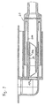
- the connector element 10 has the housing 108 in which the pipe socket 106 extends. At the end extending to the left in FIG. 1 there is an opening in housing 108, for example for receiving a Hose end. This opening and the one delimited by the pipe socket 106 Area define area 102 for guiding a medium flowing through, for example a liquid or a gas.
- the area 102 is indicated by the as Shutter element serving membrane 104 sealed.
- the puncture body 30 is received, which by means of Lock 40 is held in a desired position in the pipe socket 106.
- the locking device 40 consists of a extending on the inner circumference of the pipe socket 106, the in a corresponding circumferential groove on the outer circumference of the piercing body 30 engages.
- the puncture body has a circumferential on its outer circumference Projection 302 on.
- the connector element 20 has a housing 208 in which the pipe socket 206 is recorded. In the part of the housing 208 shown on the right in FIG. 1 a hose or any work equipment can be connected. Of the Pipe socket 206 and the adjoining area for receiving a Hose or work equipment delimit the area 202 for guiding one flowing medium. This is by a serving as a shut-off element Membrane 204 is sealed in the area of the pipe socket 206. Thus it results there is also a tight and reliable shut-off for this connector element 20 against the undesired penetration of contaminants.
- the membranes 104, 204 are hermetically sealed and free of dead spaces as injection-molded membranes and mono material, i.e. they are produced simultaneously with the Manufacture of the connector elements 10, 20. This results in a proportionate easy manufacture of the connectors according to the invention and on the other a particularly high reliability of the membranes. In particular, is an ex post Welding of film membranes or other shut-off elements and a corresponding review is unnecessary. Rather, the invention Injection molded membranes in the start phase of series production 100% and later in the sampling process by simple pressure maintenance tests for integrity being checked. This test and other property tests are carried out advantageous already at the supplier of the injection molded parts or in the quality control laboratories.
- a check on the main assembly line or a subsequent check joined membranes becomes superfluous. In addition, the separation does not apply by committee due to leakage on the main assembly line.
- a typical one Thickness of the injection molded membranes forming the shut-off elements 104, 204 is 0.2 mm.
- the connector element 10 is according to the present embodiment as integral component of a cassette-like component for fluid management and / or treatment and is produced together with this.
- the wall 12 of the cassette-like component is located directly above the housing 108. Relative to any directions of the output of the connector element 10 to the cassette wall 12, the area 102 for receiving the Piercing body 30 and the shut-off element 104 arranged such that the Puncture body from the connection side of the connector shown on the right in FIG. 1 Connector element 10 is insertable. This makes it possible to change the direction of connection in any orientation relative to the cassette-like component or to execute its wall 12. Because of such an embodiment, the Puncture body easily introduced into the corresponding receiving area become.
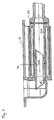
- the connector elements 10, 20 are based on that shown in FIG. 1 Assembled position, the housing 208 and is first inserted of the pipe socket 206 of the connector element 20 in the housing 108 and the Pipe socket 106 of the connector element 10 to that designed as a membrane Shut-off element 204 bears against the right end region of the piercing body 30, such as this is shown in Fig. 2.
- the housing 208 in the housing 108 and the pipe socket 206 inserted into the pipe socket 106.
- the Pipe sockets 106, 206 are in their end regions in order to facilitate this introduction beveled.
- the housing 108 and the pipe socket 106 in the corresponding parts of the connector element 20 are included.
- the piercing body 30 is not arranged in the first 10, but in the connector element 20.
- the state shown in FIG. 3 results.
- the shut-off element of the connector element 20 severed.
- the end region of the pipe socket 206 lies on the projection 302 of the piercing body 30.
- one of the shut-off elements designed as membranes, while the other Shut-off element 104 is still closed. This is due to the fact that the Piercing body 30 up to the state shown in Fig. 3 in the locked Position is held.
- a further displacement or merging of the connector elements 10, 20 finally leads to the arrangement shown in FIG. 4.
- the contact of the front End of the pipe socket 206 of the second connector element 20 with the projection 302 of the puncture body 30 leads to the puncture body 30 executing the lock 40 is released and with its pointed end shown on the left cut off as a diaphragm shut-off element. With that lies a reliable sealed and sterile passage between the connector elements 10, 20 before.
- the inside diameter of the housings 108, 208 can advantageously be selected in such a way that that effective protection against contact results from the fact that an intrusion with Fingers becomes impossible.
- the receiving connector element advantageously has one Inner diameter of 8.6 mm and the connector element to be inserted Inner diameter of 7.4 mm. Typical values for the outside diameter and the insertion depth of the connector element to be inserted is 8.4 mm or at least 22 mm.
- the connector element according to the invention ensures tightness before and after the connection. It plays over it for the safe connection process It does not matter whether the connectors are filled with liquid or gas. Subsequent Connections during use are therefore possible. The flow direction plays here not matter.
Abstract
Description
Die vorliegende Erfindung betrifft ein Konnektorelement insbesondere zum Verbinden von Schläuchen, Kanülen und Kathetern mit einem Bereich zur Führung eines durchströmenden Mediums, mit einem Absperrelement, durch das der Bereich zur Führung des Mediums verschließbar ist sowie mit einem Bereich zur Aufnahme eines Durchstoßkörpers, der derart ausgestaltet ist, daß der Durchstoßkörper relativ zu dem Absperrelement bewegbar ist und das Absperrelement bei der Konnektion durch den Durchstoßkörper geöffnet wird.The present invention relates to a connector element, in particular for connection of tubes, cannulas and catheters with an area for guiding a flowing medium, with a shut-off element through which the area to Guide of the medium is closable and with an area for receiving a piercing body, which is designed such that the piercing body is relative is movable to the shut-off element and the shut-off element during connection is opened by the piercing body.
Ein wesentliches Verwendungsgebiet für Konnektoren ist die Verbindung eines Behälters über eine Schlauchleitung mit einem medizinischen Arbeitsmittel, beispielsweise mit einem Dialysator, oder die Verbindung zweier Schlauchenden zum Zwecke der Bereitstellung von Verlängerungsleitungen. Um stets eine sterile und dichte Verbindung sicherzustellen und somit eine Gefährdung von Patienten sicher auszuschließen, werden hohe Anforderungen an die Ausführung und Qualität der Konnektoren sowie an die Art der Verbindungsbildung der Konnektoren gestellt, wodurch eine Kontamination nicht nur vor, sondern auch während und nach der Konnektion verhindert werden soll. An important area of use for connectors is the connection of a container via a hose line with medical equipment, for example with a dialyzer, or the connection of two hose ends to the Purposes of providing extension leads. To always be sterile and ensure a tight connection and thus a risk to patients exclude high demands on the execution and quality of the Connectors as well as the type of connection of the connectors, causing contamination not only before, but also during and after Connection should be prevented.
In der WO 82/02528 wird ein aus zwei Konnektorelementen aufgebautes Konnektionssystem offenbart, bei dem die Konnektorelemente vor der Konnektion mittels thermoplastischer Membranen verschlossen sind. Die Konnektorelemente sind an ihrem von der thermoplastischen Membran abgewandten Ende jeweils mit einem Schlauch verbunden, der seinerseits beispielsweise mit einem Behälter zur Aufnahme von Dialysierflüssigkeiten oder mit einem Dialysegerät in Verbindung steht. Die Konnektorelemente weisen zur Öffnung von in den Schläuchen angeordneten Schlauchmembranen ein spitz zulaufendes Ende auf. Bei der Konnektion werden zunächst die thermoplastischen Membranen in Verbindung gebracht und mittels einer geeigneten Wärmequelle geschmolzen, wodurch eine dichte Verbindung der Konnektorelemente entsteht. Im Anschluß daran erfolgt die Öffnung der Schlauchmembranen mittels der spitzen Enden der Konnektorelemente, wobei die Bewegung der spitzen Enden relativ zu den Schlauchmembranen durch einen balgartig ausgeführten Bereich des Schlauches ermöglicht wird. Der Konnektor stellt ein komplex aufgebautes System aus unterschiedlichen Membranen und Konnektorelementen auf, was die Herstellung der Konnektoren entsprechend aufwendig und teuer gestaltet.WO 82/02528 describes a connector system made up of two connector elements disclosed, in which the connector elements prior to the connection by means of thermoplastic membranes are closed. The connector elements are on their end facing away from the thermoplastic membrane in each case with a Connected hose, which in turn, for example, with a container for receiving of dialysis fluids or in connection with a dialysis machine. The connector elements point to the opening in the hoses Hose membranes on a tapered end. When connecting first connected the thermoplastic membranes and by means of a suitable heat source melted, whereby a tight connection of the Connector elements are created. The opening of the Hose membranes by means of the pointed ends of the connector elements, the Movement of the pointed ends relative to the hose membranes through a bellows executed area of the hose is made possible. The connector provides a complex system made up of different membranes and connector elements on what the manufacture of the connectors is correspondingly complex and expensive designed.
Die WO 94/08173 beschreibt ein Konnektorsystem mit zwei Konnektorelementen, die jeweils durch Membranen verschlossen sind. Nach dem Zusammenführen der Membranen wird ein verschiebbarer Dom durch die Membranen geführt, der in einem der Konnektorelemente bewegbar angeordnet ist. Im nicht konnektierten Zustand ist der Dom in einem Raum aufgenommen, der von einer der Membranen begrenzt wird. Entsprechend ist es bei der Herstellung erforderlich, die Membran nach Einführung des Dorns nachträglich am Konnektorelement zu fixieren, was den Herstellvorgang des Konnektors verhältnismäßig aufwendig gestaltet.WO 94/08173 describes a connector system with two connector elements, which are each closed by membranes. After merging the A displaceable dome is guided through the membranes in a membrane the connector elements is movably arranged. In the unconnected state the dome is recorded in a room by one of the membranes is limited. Accordingly, it is necessary to manufacture the membrane after inserting the mandrel to fix later on the connector element, which the Manufacturing process of the connector designed relatively expensive.
In der DE-OS 32 10 148 wird ein gattungsgemäßes Konnektorelement offenbart, das einen Durchstoßkörper aufweist, der relativ zu einem als Elastomermembran ausgeführten Absperrelement bewegbar ist und diese bei der Konnektion öffnet. Der Durchstoßkörper weist auf seiner Öffnungsseite einen männlichen Luer-Konus auf, der bei der Konnektion mit einem entsprechenden weiblichen Konus zusammenwirkt. Die Elastomermembran erstreckt sich über den Bereich zur Führung eines durchströmenden Mediums und verschließt diesen im dekonnektierten Zustand. Die Membran liegt an einer Stufe des Konnektorelementes an und wird dort mittels eines Paßstückes angepreßt. Einem derartigen Konnektorelement ist es nachteilig, daß dieses aus mehreren unterschiedlichen Materialien aufgebaut ist und daß die Membran nachträglich eingeführt und flüssigkeitsdicht fixiert werden muß.In DE-OS 32 10 148 a generic connector element is disclosed which has a puncture body which is relative to one as an elastomeric membrane executed shut-off element is movable and opens this at the connection. The piercing body has a male Luer cone on its opening side which cooperates with a corresponding female cone during the connection. The elastomeric membrane extends over the area for guiding one flowing medium and closes it in the disconnected state. The membrane lies against a step of the connector element and is there pressed by means of a fitting. It is such a connector element disadvantage that this is made up of several different materials and that the membrane is inserted later and fixed liquid-tight got to.
Es ist die Aufgabe der vorliegenden Erfindung, einen gattungsgemäßen Konnektor dahingehend weiterzubilden, daß dieser einfach herstellbar ist und eine zuverlässige Konnektion sicherstellt.It is the object of the present invention, a generic connector to further develop that this is easy to manufacture and reliable Ensures connection.
Diese Aufgabe wird ausgehend von einem gattungsgemäßen Konnektorelement dadurch gelöst, daß das Absperrelement als monomaterialer Bestandteil des Konnektorelementes ausgeführt ist. Dadurch wird eine verhältnismäßig einfache Herstellung der Konnektorelemente ermöglicht, da das Absperrelement integraler Bestandteil des Konnektorelementes ist und eine nachträgliche Positionierung und Fixierung nicht nötig ist. Ein nachträgliches Aufbringen von Membranen ist somit nicht erforderlich. Dadurch vereinfacht sich nicht nur die Herstellung der Konnektoren, sondern aufgrund der Möglichkeit, die Konnektorelemente und Absperrelemente in einem Arbeitsschritt herzustellen, wird zudem eine besonders dichte Anordnung erreicht. Eine nachträgliche Einschweißung beispielsweise von Folienmembranen oder das nachträgliche Anschweißen oder Anordnen von membranbe-stückten Einzelbauteilen und eine entsprechend aufwendige Überprüfung können entsprechend entfallen.This task is based on a generic connector element solved in that the shut-off element as a monomaterial component of the connector element is executed. This makes it relatively easy to manufacture the connector elements allows because the shut-off element is an integral part of the connector element and a subsequent positioning and Fixation is not necessary. Subsequent application of membranes is thus not mandatory. This not only simplifies the manufacture of the connectors, but because of the possibility of the connector elements and shut-off elements Manufacturing in one step also becomes a particularly dense arrangement reached. Subsequent welding, for example of film membranes or the subsequent welding or arrangement of membrane-populated Individual components and a correspondingly complex inspection can accordingly eliminated.
Gemäß einer bevorzugten Ausgestaltung der vorliegenden Erfindung ist das Absperrelement als Spritzgußmembran ausgeführt. Die Spritzgußmembran kann im gleichen Arbeitsgang mit dem Konnektorelement hergestellt werden, wodurch ein nachträgliches Aufbringen von Absperrelementen beliebiger Form überflüssig wird. Insbesondere ergibt sich dadurch eine besonders dichte und totraumfreie Ausgestaltung des erfindungsgemäßen Konnektorelementes. Dabei wird nicht nur ein Auslaufschutz bzw. ein Schutz vor Bakterien sichergestellt, sondern auch eine dauerhafte Dichtigkeit bis zu mehreren Bar Differenzdruck.According to a preferred embodiment of the present invention, the shut-off element is designed as an injection molded membrane. The injection molding membrane can same operation can be made with the connector element, creating a subsequent application of shut-off elements of any shape becomes unnecessary. In particular, this results in a particularly dense and dead space-free design of the connector element according to the invention. It won't just be one Leakage protection or protection against bacteria is ensured, but also permanent Tightness up to several bar differential pressure.
In weiterer Ausgestaltung der vorliegenden Erfindung ist vorgesehen, daß der Bereich zur Führung des Mediums den Bereich zur Aufnahme des Durchstoßkörpers umfaßtIn a further embodiment of the present invention it is provided that the area to guide the medium, the area for receiving the piercing body includes
Besonders vorteilhaft ist es, wenn der Bereich zur Führung des Mediums einen Rohrstutzen umfaßt.It is particularly advantageous if the area for guiding the medium is one Pipe socket includes.
In weiterer Ausgestaltung der vorliegenden Erfindung ist vorgesehen, daß das Konnektorelement ein Gehäuse aufweist und der Rohrstutzen in dem Gehäuse aufgenommen ist. Dabei kann erfindungsgemäß der Rohrstutzen durch das Absperrelement, beispielsweise eine Membran, verschlossen sein, wodurch die Dichtheit und Sterilität der angeschlossenen Schläuche oder Behälter sichergestellt wird. Vorteilhaft ist es, wenn der Durchstoßkörper in dem Rohrstutzen angeordnet ist. Erfindungsgemäß erfolgt die Anordnung derart, daß bei der Konnektion eine Durchtrennung bzw. Öffnung des Absperrelementes durch den Durchstoßkörper erfolgt. Das Gehäuse kann dazu dienen, den Rohrstutzen sowie das Absperrelement gegen unerwünschtes Berühren und Einbringen von Verunreinigungen zu schützen. Dabei kann der Gehäusedurchmesser derart ausgelegt werden, daß eine versehentliche Berührung des Rohrstutzens bzw. der Bereiche, die nach der Konnektion mit Flüssigkeit oder Gas beaufschlagt werden, nicht möglich ist.In a further embodiment of the present invention it is provided that the Connector element has a housing and the pipe socket in the housing is recorded. According to the invention, the pipe socket through the shut-off element, For example, a membrane, be closed, which results in tightness and sterility of the connected hoses or containers is ensured. It is advantageous if the piercing body is arranged in the pipe socket. According to the invention, the arrangement is such that a Cutting or opening the shut-off element through the piercing body he follows. The housing can serve the pipe socket as well as the shut-off element against unwanted touching and introduction of contaminants protect. The housing diameter can be designed such that a accidental contact with the pipe socket or the areas after the connection with liquid or gas, is not possible.
Besonders vorteilhaft ist es, wenn ein Durchstoßkörper vorgesehen ist, der in den Rohrstutzen einführbar und dort mittels einer Arretierung fixierbar ist.It is particularly advantageous if a puncture body is provided, which in the Pipe socket can be inserted and fixed there by means of a lock.
Dabei kann die Arretierung eine am Außenumfang des Durchstoßkörpers umlaufende Nut und einen sich am Innenumfang des Rohrstutzens erstreckenden Vorsprung umfassen. Bei oder nach der Herstellung bzw. vor der Benutzung des Konnektors kann der Durchstoßkörper entsprechend in den Rohrstutzen eingeführt werden und durch die Arretierung in der gewünschten Position gehalten werden.The locking device can run around the outer circumference of the piercing body Groove and a projection extending on the inner circumference of the pipe socket include. During or after the manufacture or before using the connector the piercing body can be inserted into the pipe socket accordingly and are held in the desired position by the lock.
Gemäß einer bevorzugten Ausgestaltung der vorliegenden Erfindung ist vorgesehen, daß der Durchstoßkörper derart ausgeführt ist, daß dieser durch einen Rohrstutzen eines mit dem Konnektorelement zu verbindenden weiteren Konnektorelementes aus der Arretierung lösbar ist. Dadurch wird erreicht, daß erst während der Konnektion der Durchstoßkörper aus seiner Arretierung gelöst wird und mittels eines Rohrstutzens derart bewegt wird, daß die Durchtrennung bzw. Öffnung des Absperrelementes erfolgt. Dabei ist die Arretierung vorteilhaft derart ausgelegt, daß zunächst das Absperrelement eines der Konnektorelemente durchtrennt wird, bevor der entsprechende Rohrstutzen den Durchstoßkörper aus der Arretierung löst und anschließend das zweite Absperrelement bzw. die zweite Membran durchtrennt.According to a preferred embodiment of the present invention, that the piercing body is designed such that this through a pipe socket a further connector element to be connected to the connector element is detachable from the lock. This ensures that only during the Connection of the piercing body is released from its locking and by means of a Pipe socket is moved such that the severing or opening of the Shut-off element takes place. The lock is advantageously designed such that the shut-off element of one of the connector elements is first cut before the corresponding pipe socket releases the puncture body from the detent and then the second shut-off element or the second membrane is severed.
Das Lösen des Durchstoßkörpers aus der Arretierung kann dadurch erfolgen, daß dieser einen am Außenumfang angeordneten Vorsprung aufweist, der mit dem Rohrstutzen eines mit dem Konnektorelement zu verbindenden weiteren Konnektorelementes verbindbar ist.The piercing body can be released from the locking device in that this has a projection arranged on the outer circumference, which with the Pipe socket of a further connector element to be connected to the connector element is connectable.
In weiterer Ausgestaltung der vorliegenden Erfindung ist vorgesehen, daß in dem Gehäuse und dem Rohrstutzen des Konnektorelementes das Gehäuse und der Rohrstutzen eines mit dem Konnektorelement zu verbindenden weiteren Konnektorelementes wenigstens teilweise aufnehmbar sind. Dies wird durch eine entsprechende Ausgestaltung der Innen- bzw. Außendurchmesser der aneinandergrenzenden Bauteile erreicht.In a further embodiment of the present invention it is provided that in the Housing and the pipe socket of the connector element, the housing and the Pipe socket of a further connector element to be connected to the connector element are at least partially recordable. This is done by an appropriate Design of the inner or outer diameter of the adjacent Components reached.
Besonders vorteilhaft ist es, wenn der Rohrstutzen in seinem Endbereich abgeschrägt ist. Dadurch wird das Einschieben eines der Rohrstutzen in den diesen aufnehmenden Rohrstutzen erleichtert, wobei vorteilhaft eine Aufweitung des aufnehmenden Rohrstutzens erfolgt, was eine besonders dichte Verbindung beider Rohrstutzen sicherstellt. Die Konnektion und erforderlichenfalls die Dekonnektion kann maschinell oder auch von Hand ausgeführt werden. Vorteilhaft ist es, wenn die Dekonnektion konstruktiv bedingt mit einem höheren Kraftbedarf verbunden ist als die Konnektion. Bei Bedarf lassen sich konstruktive Elemente, beispielsweise spritzgußtechnisch, integrieren, die eine Dekonnektion unmöglich machen.It is particularly advantageous if the pipe socket is beveled in its end region is. This will push one of the pipe sockets into this receiving pipe socket facilitates, advantageously expanding the receiving Pipe socket takes place, which is a particularly tight connection between the two Ensures pipe socket. The connection and, if necessary, the disconnection can be done by machine or by hand. It is advantageous if the deconnection is connected with a higher power requirement due to the design than the connector. If necessary, constructive elements, for example injection molding, integrate that make disconnection impossible.
Vorteilhaft ist es, wenn der Durchstoßkörper eine im wesentlichen zylindrische Form aufweist und an seinen Enden spitz zuläuft. Dadurch wird verhältnismäßig einfache und wenig Kraft beanspruchende Öffnung der Absperrelemente bzw. Membranen ermöglicht. Ebenso ist es möglich, den Durchstoßkörper gekerbt oder gelocht auszuführen oder in einer Sternprofilform vorzusehen.It is advantageous if the piercing body is essentially cylindrical Form and pointed at its ends. This makes it proportional simple and low-force opening of the shut-off elements or Enables membranes. It is also possible to notch the puncture body or perforated or in a star profile shape.
In weiterer Ausgestaltung der vorliegenden Erfindung ist vorgesehen, daß das Konnektorelement sowie der Durchstoßkörper als Spritzgußteile ausgeführt sind. Die Herstellung läßt sich kostengünstig in Vielfach-Spritzgießwerkzeugen durchführen. Dies ermöglicht eine einfache Herstellung der Teile in vielfältigen möglichen Ausführungsformen.In a further embodiment of the present invention it is provided that the Connector element and the piercing body are designed as injection molded parts. The production can be carried out inexpensively in multiple injection molds. This enables the parts to be easily manufactured in many different ways Embodiments.
Besonders vorteilhaft ist es, wenn das Konnektorelement mit Absperrelement sowie der Durchstoßkörper Polypropylen aufweisen.It when the connector element with shut-off element and the piercing body has polypropylene.
Gemäß einer bevorzugten Ausgestaltung der vorliegenden Erfindung weisen das Gehäuse sowie der Rohrstutzen des Konnektorelementes zylindrische Außen- und Innenflächen auf Dies hat den Vorteil, daß weder bei der Herstellung noch bei der Anwendung des Konnektorsystems Drehpositionierungen erforderlich sind. Vielmehr kann die Konnektion durch einfaches Einstecken eines des Konnektorelementes in das andere Konnektorelement erfolgen. Bei entsprechender Ausgestaltung des Gehäuses der Konnektorelemente kann erreicht werden, daß sich ein besonders guter Berührschutz ergibt. Typische Werte für die Gehäuseinnendurchmesser sind 8,6 mm beim aufnehmenden und 7,4 mm beim einzuführenden Konnektorelement, was einen guten Berührschutz auch gegen das Eindringen dünner Fingerkuppen gewährleistet. According to a preferred embodiment of the present invention, this Housing and the pipe socket of the connector element cylindrical outer and Inner surfaces on this has the advantage that neither in the manufacture nor in the Application of the connector system rotary positions are required. Much more can the connection by simply inserting one of the connector element into the other connector element. With an appropriate design the housing of the connector elements can be achieved that a special good protection against contact results. Typical values for the inside diameter of the housing are 8.6 mm for the female connector and 7.4 mm for the male connector, which is good protection against accidental contact also against the penetration thinner Guaranteed fingertips.
Besonders vorteilhaft ist es, wenn die Innen- oder Außenflächen der Rohrstutzen abgeschrägt oder konisch ausgeführt sind. Hierdurch ergibt sich der Vorteil, daß bereits eine dichte Verbindung zwischen zwei zu verbindenden Konnektorelementen hergestellt wird, bevor die Absperrelemente der Konnektorelemente durchstoßen werden.It is particularly advantageous if the inner or outer surfaces of the pipe socket beveled or conical. This has the advantage that already a tight connection between two connector elements to be connected is produced before the shut-off elements of the connector elements penetrate become.
Die Rohrstutzen können in ihrem Endbereich auf der Innen- oder Außenfläche einen umlaufenden Vorsprung aufweisen, mittels dessen eine dichtende Verbindung mit einem einzuführenden oder aufnehmenden Rohrstutzen eines weiteren Konnektorelementes herstellbar ist. Auch hieraus ergibt sich der Vorteil, daß eine Abdichtung gegenüber der Umgebungsatmosphäre erfolgt, bevor es zu einem Durchstoßen der Absperrelemente bzw. der Membranen kommt. Entsprechend gefährden auch Über- und Unterdrücke zwischen den flüssigkeits- und gasgefüllten Zonen der Konnektorelemente relativ zur Umgebung und Druckunterschiede zwischen den Konnektorelementen, die je nach Dimensionierung der Anordnung bis zu mehreren Bar betragen, nicht die Sterilität und die Dichtigkeit vor, während und nach der Konnektion, da stets zuerst eine dichte Verbindung zwischen den zu verbindenden Konnektorelementen hergestellt wird, und erst im nächsten Schritt die Verschlußmembranen durchstoßen werden.The end of the pipe socket can be on the inside or outside surface have circumferential projection, by means of which a sealing connection with an inserted or receiving pipe socket of another connector element can be produced. This also has the advantage that a seal relative to the ambient atmosphere before it pierces the shut-off elements or the membranes comes. Endanger accordingly also high and low pressures between the liquid and gas-filled zones of the connector elements relative to the environment and pressure differences between the connector elements, depending on the dimensioning of the arrangement up to several Bar amount, not sterility and tightness before, during and after of the connection, since there is always a tight connection between those to be connected Connector elements is produced, and only in the next step the sealing membranes be pierced.
In weiterer Ausgestaltung der vorliegenden Erfindung ist vorgesehen, daß das Absperrelement sowie der Bereich zur Aufnahme des Durchstoßkörpers derart angeordnet sind, daß der Durchstoßkörper von der Konnektionsseite des Konnektorelementes einführbar ist. Dabei ist unter dem Begriff Konnektionsseite die Seite des Konnektorelementes zu verstehen, auf der ein zu verbindendes Konnektorelement eingeführt bzw. aufgesteckt werden soll. Eine derartige Anordnung ist insbesondere dann von Vorteil, wenn das erfindungsgemäße Konnektorelement integraler Bestandteil beispielsweise eines Spritzgußbauteils ist, d.h. wenn das Konnektorelement zusammen mit diesem Bauteil hergestellt wird. Ein derartiges Bauteil kann z.B. ein kassettenartiges Bauteil für die Fluidführung und/oder -behandlung sein. Um Konnektorausgänge zu realisieren, die in verschiedenen und beliebigen Richtungen relativ beispielsweise zu einer Wandung eines kassettenartigen Bauteils verlaufen, ist das Absperrelement bzw. die Membran derart angeordnet, daß der Durchstoßkörper von außen bzw. von der Konnektionsseite einführbar ist.In a further embodiment of the present invention it is provided that the shut-off element and the area for receiving the piercing body are arranged in this way are that the piercing body from the connector side of the connector element can be introduced. The term connection side is the side of the To understand connector element on which a connector element to be connected should be introduced or plugged on. Such an arrangement is special then advantageous if the connector element according to the invention is an integral part for example an injection molded component, i.e. if the connector element is produced together with this component. Such a component can e.g. be a cassette-like component for fluid management and / or treatment. To realize connector outputs in different and arbitrary directions relative, for example, to a wall of a cassette-like component run, the shut-off element or the membrane is arranged such that the Piercing body can be inserted from the outside or from the connection side.
Weitere Einzelheiten und Vorteile der vorliegenden Erfindung werden anhand eines in der Zeichnung dargestellten Ausführungsbeispiels näher erläutert. Es zeigen:
- Fig. 1:
- Eine Schnittdarstellung durch zwei erfindungsgemäße Konnektorelemente in einer Grundstellung vor der Konnektion,
- Fig. 2:
- die Konnektorelemente gemäß Fig. 1 nach dem Einführen des rechts dargestellten Konnektorelementes bis zum Anliegen der Membran an dem Durchstoßkörper,
- Fig. 3:
- die Konnektorelemente gemäß Fig. 1 nach dem Öffnen der Membran des rechts dargestellten Konnektorelementes und
- Fig. 4:
- die Konnektorelemente gemäß Fig. 1 nach dem Durchtrennen beider Membranen durch den Durchstoßkörper.
- Fig. 1:
- A sectional view through two connector elements according to the invention in a basic position before the connection,
- Fig. 2:
- 1 after inserting the connector element shown on the right until the membrane abuts the piercing body,
- Fig. 3:
- 1 after opening the membrane of the connector element shown on the right and
- Fig. 4:
- 1 after the two membranes have been severed by the piercing body.
Fig. 1 zeigt zwei Konnektorelemente 10, 20 vor dem Zusammenführen in einer
Grundposition. Das Konnektorelement 10 weist das Gehäuse 108 auf, in dem sich
der Rohrstutzen 106 erstreckt. An dem sich gemäß Fig. 1 links erstreckenden Ende
des Gehäuses 108 befindet sich eine Öffnung beispielsweise zur Aufnahme eines
Schlauchendes. Diese Öffnung sowie der durch den Rohrstutzen 106 begrenzte
Bereich definieren den Bereich 102 zur Führung eines durchströmenden Mediums,
beispielsweise einer Flüssigkeit oder eines Gases. Der Bereich 102 ist durch die als
Absperrelement dienende Membran 104 dicht verschlossen.1 shows two
In dem Rohrstutzen 106 ist der Durchstoßkörper 30 aufgenommen, der mittels der
Arretierung 40 in einer gewünschten Position im Rohrstutzen 106 gehalten wird.
Die Arretierung 40 besteht gemäß dem vorliegenden Ausführungsbeispiel aus einem
sich am Innenumfang des Rohrstutzens 106 erstreckenden Vorsprung, der in
einer entsprechenden umlaufenden Nut am Außenumfang des Durchstoßkörpers
30 eingreift. Der Durchstoßkörper weist an seinem Außenumfang einen umlaufenden
Vorsprung 302 auf.In the
Das Konnektorelement 20 weist ein Gehäuse 208 auf, in dem der Rohrstutzen 206
aufgenommen ist. In dem in Fig. 1 rechts dargestellten Teil des Gehäuses 208
kann ein Schlauch oder ein beliebiges Arbeitsmittel angeschlossen werden. Der
Rohrstutzen 206 sowie sich der daran anschließende Bereich zur Aufnahme eines
Schlauches oder Arbeitsmittels begrenzen den Bereich 202 zur Führung eines
durchströmenden Mediums. Dieser ist durch eine als Absperrelement dienende
Membran 204 im Bereich des Rohrstutzens 206 dicht verschlossen. Somit ergibt
sich auch für dieses Konnektorelement 20 eine dichte und zuverlässige Absperrung
gegen das unerwünschte Eindringen von Verunreinigungen.The
In dem gemäß Fig. 1 rechts dargestellten Endbereich des Rohrstutzens 106 befindet
sich der umlaufende Vorsprung 107. Dieser dient dazu, während der Konnektion
der Konnektorelemente 10, 20 eine dichte Verbindung zwischen den Rohrstutzen
106, 206 der Konnektorelemente 10, 20 zu bewirken. Daraus ergibt sich der
Vorteil, daß vor dem Durchstoßen der Absperrelemente 104, 204 bereits eine Abdichtung
gegen die Umgebung erfolgt, wodurch die Sterilität und die Dichtigkeit der
Verbindung vor, während und nach der Konnektion sichergestellt wird.In the end region of the
Die Membranen 104, 204 sind als Spritzgußmembranen hermetisch dicht, totraumfrei
und monomaterial ausgeführt, d.h., deren Herstellung erfolgt gleichzeitig mit der
Herstellung der Konnektorelemente 10, 20. Daraus ergibt sich eine verhältnismäßig
einfache Herstellbarkeit der erfindungsgemäßen Konnektoren und zum anderen
eine besonders hohe Zuverlässigkeit der Membranen. Insbesondere ist eine nachträgliche
Einschweißung von Folienmembranen oder anderen Absperrelementen
und eine entsprechende Überprüfung überflüssig. Vielmehr können die erfindungsgemäßen
Spritzgußmembranen in der Startphase der Serienproduktion zu 100 %
und später im Stichprobenverfahren durch einfache Druckhalteprüfungen auf Integrität
geprüft werden. Diese Prüfung sowie weitere Eigenschaftsprüfungen erfolgen
vorteilhaft schon beim Lieferanten der Spritzgußteile bzw. in den Labors der Qualitätskontrolle.
Eine Kontrolle am Hauptmontageband bzw. die Überprüfung nachträglich
gefügter Membranen wird überflüssig. Darüber hinaus entfällt die Aussonderung
von Ausschuß aufgrund Undichtigkeit am Hauptmontageband. Eine typische
Stärke der die Absperrelemente 104, 204 bildenden Spritzgußmembranen
beträgt 0,2 mm.The
Das Konnektorelement 10 ist gemäß dem vorliegenden Ausführungsbeispiel als
integraler Bestandteil eines kassettenartigen Bauteils für die Fluidführung und/oder
-behandlung ausgeführt und wird zusammen mit diesem hergestellt. Die Wandung
12 des kassettenartigen Bauteils befindet sich unmittelbar oberhalb des Gehäuses
108. Um beliebige Richtungen des Ausgangs des Konnektorelementes 10 relativ
zur Kassettenwand 12 zu ermöglichen, ist der Bereich 102 zur Aufnahme des
Durchstoßkörpers 30 sowie das Absperrelement 104 derart angeordnet, daß der
Durchstoßkörper von der gemäß Fig. 1 rechts dargestellten Konnektionsseite des
Konnektorelementes 10 einführbar ist. Dadurch wird es möglich, die Konnektionsrichtung
in beliebiger Orientierung relativ zu dem kassettenartigen Bauteil bzw. zu
dessen Wandung 12 auszuführen. Aufgrund einer derartigen Ausführung kann der
Durchstoßkörper problemlos in den entsprechenden Aufnahmebereich eingebracht
werden.The
Um einen weiten Anwendungsbereich eines derartigen kassettenartigen Bauteils zu
gewährleisten ist es besonders vorteilhaft, den Durchstoßkörper 30 in das kassettenseitige
Konnektorelement 10 einzubringen. Dies ist insbesondere dann erforderlich,
wenn das mit dem kassettenseitigen Konnektorelement zu verbindende Konnektorelement
nicht von einem Disposable, wie z.B. einem Schlauch, herrührt, sondern
direkt einen maschinenseitigen Anschluß darstellt, der nicht ständig ausgewechselt
wird.To a wide range of applications of such a cassette-like component
it is particularly advantageous to ensure that the piercing
Werden die Konnektorelemente 10, 20 ausgehend von der in Fig. 1 dargestellten
Position zusammengefügt, erfolgt zunächst ein Einführen des Gehäuses 208 und
des Rohrstutzens 206 des Konnektorelementes 20 in das Gehäuse 108 und den
Rohrstutzen 106 des Konnektorelementes 10 bis das als Membran ausgeführte
Absperrelement 204 am rechten Endbereich des Durchstoßkörpers 30 anliegt, wie
dies in Fig. 2 dargestellt ist. Beim Zusammenführen werden das Gehäuse 208 in
das Gehäuse 108 und der Rohrstutzen 206 in den Rohrstutzen 106 eingefügt. Die
Rohrstutzen 106, 206 sind, um diese Einführung zu erleichtern, in ihren Endbereichen
abgeschrägt. Neben der in Fig. 2 gezeigten Anordnung ist es möglich, daß
das Gehäuse 108 und der Rohrstutzen 106 in die entsprechenden Teile des Konnektorelementes
20 aufgenommen werden. Auch ist es denkbar, daß der Durchstoßkörper
30 nicht im ersten 10, sondern im Konnektorelement 20 angeordnet ist.The
Während des Zusammenfügens der Konnektorelemente 10, 20 gemäß Fig. 2
kommt es zu einer Verbindung des umlaufenden Vorsprungs 107 des Rohrstutzens
106 mit der Außenfläche des eingeführten Rohrstutzens 206 des Konnektorelementes
20. Hierdurch wird sichergestellt, daß bereits eine Abdichtung gegen die
Umgebungsatmosphäre erfolgt, bevor die Absperrelemente 104, 204 durchstoßen
werden.During the joining of the
Werden die Konnektorelemente ausgehend von Fig. 2 weiter zusammengeführt,
ergibt sich der in Fig. 3 dargestellte Zustand. Hier hat bereits die rechte, spitz zulaufende
Kante des Durchstoßkörpers 30 das Absperrelement des Konnektorelementes
20 durchtrennt. Ferner liegt der Endbereich des Rohrstutzens 206 am Vorsprung
302 des Durchstoßkörpers 30 an. In diesem Stadium ist bereits eines der
als Membranen ausgeführten Absperrelemente durchtrennt, während das andere
Absperrelement 104 noch verschlossen ist. Dies ist darauf zurückzuführen, daß der
Durchstoßkörper 30 bis zu dem in Fig. 3 dargestellten Zustand in der arretierten
Position gehalten wird.If the connector elements are further brought together on the basis of FIG. 2,
the state shown in FIG. 3 results. Here already has the right, tapering one
Edge of the piercing
Ein weiteres Verschieben bzw. Zusammenführen der Konnektorelemente 10, 20
führt schließlich zu der in Fig. 4 dargestellten Anordnung. Der Kontakt des vorderen
Endes des Rohrstutzens 206 des zweiten Konnektorelementes 20 mit dem Vorsprung
302 des Durchstoßkörpers 30 führt dazu, daß der Durchstoßkörper 30 aus
der Arretierung 40 gelöst wird und mit seinem links dargestellten spitzen Ende das
als Membran ausgeführte Absperrelement durchtrennt. Damit liegt ein zuverlässig
abgedichteter und steriler Durchlaß zwischen den Konnektorelementen 10, 20 vor.A further displacement or merging of the
Neben der in Fig. 1 bis 4 dargestellten Ausführungsform ist es ebenfalls möglich,
daß zunächst das Absperrelement 104 des Konnektorelementes 10 durchtrennt
wird und anschließend das Absperrelement 204 des Konnektorelementes 20. Dazu
wäre erforderlich, daß der Durchstoßkörper 30 nach dem Durchtrennen des Absperrelementes
104 an einem Anschlag anliegt, wodurch eine Relativbewegung
zwischen Durchstoßkörper 30 und dem Absperrelement 204 des Konnektorelementes
20 erfolgen kann.In addition to the embodiment shown in FIGS. 1 to 4, it is also possible
that first the cut-off
Der Innendurchmesser der Gehäuse 108, 208 kann vorteilhaft derart gewählt werden,
daß sich ein wirksamer Berührschutz dadurch ergibt, daß ein Eindringen mit
Fingern unmöglich wird. Vorteilhaft weist das aufnehmende Konnektorelement einen
Innendurchmesser von 8,6 mm und das einzuführende Konnektorelement einen
Innendurchmesser von 7,4 mm auf. Typische Werte für den Außendurchmesser
und die Einstecktiefe des einzuführenden Konnektorelementes sind 8,4 mm
bzw. minimal 22 mm.The inside diameter of the
Das erfindungsgemäße Konnektorelement gewährleistet Dichtheit vor, während und nach der Konnektion. Für den sicheren Konnektionsvorgang spielt es darüber hinaus keine Rolle, ob die Konnektoren flüssigkeits- oder gasgefüllt sind. Nachträgliche Konnektionen während des Einsatzes sind also möglich. Dabei spielt die Flußrichtung keine Rolle.The connector element according to the invention ensures tightness before and after the connection. It plays over it for the safe connection process It does not matter whether the connectors are filled with liquid or gas. Subsequent Connections during use are therefore possible. The flow direction plays here not matter.
Claims (18)
dadurch gekennzeichnet,
characterized by
Applications Claiming Priority (2)
| Application Number | Priority Date | Filing Date | Title |
|---|---|---|---|
| DE19828650A DE19828650C2 (en) | 1998-06-26 | 1998-06-26 | Connector element with integrated shut-off element |
| DE19828650 | 1998-06-26 |
Publications (3)
| Publication Number | Publication Date |
|---|---|
| EP0966984A2 true EP0966984A2 (en) | 1999-12-29 |
| EP0966984A3 EP0966984A3 (en) | 2000-03-29 |
| EP0966984B1 EP0966984B1 (en) | 2005-08-17 |
Family
ID=7872187
Family Applications (1)
| Application Number | Title | Priority Date | Filing Date |
|---|---|---|---|
| EP99111745A Expired - Lifetime EP0966984B1 (en) | 1998-06-26 | 1999-06-17 | Connector element |
Country Status (5)
| Country | Link |
|---|---|
| US (1) | US6234538B1 (en) |
| EP (1) | EP0966984B1 (en) |
| JP (1) | JP4287952B2 (en) |
| DE (2) | DE19828650C2 (en) |
| ES (1) | ES2248943T3 (en) |
Cited By (3)
| Publication number | Priority date | Publication date | Assignee | Title |
|---|---|---|---|---|
| EP2266631A1 (en) * | 2000-02-07 | 2010-12-29 | Ethicon, Inc. | Method and system for delivering and metering liquid sterilant |
| WO2011091895A1 (en) * | 2010-01-26 | 2011-08-04 | Raumedic Ag | Sealing sleeve body |
| US9700665B2 (en) | 2011-07-29 | 2017-07-11 | Fresenius Medical Care Deutschland Gmbh | Contact protection apparatus for a medical fluid-conducting cassette and cassette |
Families Citing this family (31)
| Publication number | Priority date | Publication date | Assignee | Title |
|---|---|---|---|---|
| JP2002526736A (en) * | 1998-10-02 | 2002-08-20 | エアロクイップ コーポレーション | Fitting assembly |
| US6471249B1 (en) * | 1998-10-08 | 2002-10-29 | John K. Lewis | Adjustable pipe connector |
| CA2373689A1 (en) * | 1999-07-29 | 2001-02-08 | Thomas W. Coneys | Sampling tube holder for blood sampling system |
| US20030176813A1 (en) * | 1999-07-29 | 2003-09-18 | Jean-Marie Mathias | Biological fluid sampling apparatus |
| US7435231B2 (en) * | 1999-07-29 | 2008-10-14 | Fenwal, Inc. | Biological sample device receiver |
| US7824343B2 (en) * | 1999-07-29 | 2010-11-02 | Fenwal, Inc. | Method and apparatus for blood sampling |
| SE0001278L (en) * | 2000-04-06 | 2001-10-08 | Peter Unger Med P U Med Konsul | sterile Coupling |
| DE10136262A1 (en) | 2001-07-25 | 2003-02-20 | Fresenius Medical Care De Gmbh | Method and device as well as connector and concentrate container unit for the preparation of solutions |
| ITMI20020819A1 (en) * | 2002-04-18 | 2003-10-20 | Gambro Lundia Ab | CONNECTION ELEMENT AND CONNECTION DEVICE FOR MEDICAL USE PIPES |
| US6902207B2 (en) * | 2002-05-01 | 2005-06-07 | Medtronic Minimed, Inc. | Self sealing disconnect device |
| US8215492B2 (en) | 2003-09-18 | 2012-07-10 | Pur Water Purification Products, Inc. | Water treatment devices and cartridges therefor |
| ITMO20040082A1 (en) * | 2004-04-13 | 2004-07-13 | Gambro Lundia Ab | CONNECTOR FOR A FLUID LINE OF AN EXTACORPOREO CIRCUIT |
| DE602007009987D1 (en) * | 2006-07-07 | 2010-12-02 | Caridianbct Inc | Method for connecting thermoplastic hoses |
| CA2670751A1 (en) * | 2006-12-05 | 2008-06-12 | Caridianbct, Inc. | Connector system for sterile connection |
| US8764702B2 (en) * | 2007-07-05 | 2014-07-01 | Baxter International Inc. | Dialysis system having dual patient line connection and prime |
| US7901376B2 (en) * | 2007-07-05 | 2011-03-08 | Baxter International Inc. | Dialysis cassette having multiple outlet valve |
| US8496609B2 (en) | 2007-07-05 | 2013-07-30 | Baxter International Inc. | Fluid delivery system with spiked cassette |
| US7955295B2 (en) * | 2007-07-05 | 2011-06-07 | Baxter International Inc. | Fluid delivery system with autoconnect features |
| US8197087B2 (en) | 2007-07-05 | 2012-06-12 | Baxter International Inc. | Peritoneal dialysis patient connection system using ultraviolet light emitting diodes |
| US8157761B2 (en) | 2007-07-05 | 2012-04-17 | Baxter International Inc. | Peritoneal dialysis patient connection system |
| US7736328B2 (en) * | 2007-07-05 | 2010-06-15 | Baxter International Inc. | Dialysis system having supply container autoconnection |
| US20090143723A1 (en) * | 2007-11-29 | 2009-06-04 | Baxter International Inc. | Flow control device for peritoneal dialysis |
| US9044544B2 (en) * | 2008-11-21 | 2015-06-02 | Baxter International Inc. | Dialysis machine having auto-connection system with roller occluder |
| US20100211040A1 (en) * | 2009-02-19 | 2010-08-19 | Cetylite Industries, Inc. | Apparatus and method for dispensing fluid through a port connector |
| CN104768605A (en) * | 2012-08-28 | 2015-07-08 | 费森尤斯卡比德国有限公司 | Connector for producing a fluid connection to a second connector, connector system, and method for producing a fluid connection |
| US10441458B2 (en) | 2015-01-27 | 2019-10-15 | Medicance Incorporated | Medical pad and system for thermotherapy |
| WO2016205837A1 (en) * | 2015-06-16 | 2016-12-22 | Walterspiel Juan | Tubing connector for decreased contamination |
| US20200408350A1 (en) | 2015-06-16 | 2020-12-31 | Juan Nepomuc Walterspiel | Tubing connector for decreased contamination |
| DE102017101730A1 (en) | 2017-01-30 | 2018-08-02 | Fresenius Medical Care Deutschland Gmbh | New shock protection device for medical fluid-carrying cassette and cassette |
| IL268433B2 (en) * | 2017-02-10 | 2024-03-01 | Lonza Ag | Cell culture system and method |
| US20220288374A1 (en) * | 2021-03-11 | 2022-09-15 | Bellco S.R.L. | Connector system |
Citations (5)
| Publication number | Priority date | Publication date | Assignee | Title |
|---|---|---|---|---|
| US4161949A (en) * | 1977-10-27 | 1979-07-24 | Pennwalt Corporation | Aseptic connector |
| US4195632A (en) * | 1978-05-03 | 1980-04-01 | Cutter Laboratories, Inc. | Fluid flow valve |
| US4457749A (en) * | 1982-04-19 | 1984-07-03 | Baxter Travenol Laboratories, Inc. | Shield for connectors |
| US4636204A (en) * | 1982-04-13 | 1987-01-13 | Gambro Lundia Ab | Coupling for the connection of flexible tubes and the like |
| EP0830874A2 (en) * | 1996-09-17 | 1998-03-25 | Fresenius AG | Connector device for medical use |
Family Cites Families (21)
| Publication number | Priority date | Publication date | Assignee | Title |
|---|---|---|---|---|
| DE1070054B (en) * | 1959-11-26 | Hellerup Kopenhagen Svend Axel Jörgen Manis'led (Dänemark); Vemr.: Dipl.-Ing. C-H. Huß, Pat-An»., Garmisch-Partenkirchen | Lock for containers for storing volatile, liquid or gaseous contents | |
| DE1300635B (en) * | 1964-09-07 | 1969-08-07 | Dr Med Karl Friedrich | Sterile line connection for the flow of transfusion or infusion fluids |
| ES319553A1 (en) * | 1964-11-17 | 1966-05-01 | Projecteurs Cibiei | A set of couplings for elements of hydraulic circuit. (Machine-translation by Google Translate, not legally binding) |
| US3466065A (en) * | 1968-04-04 | 1969-09-09 | Weatherhead Co | Rupturable diaphragm coupling |
| US4030494A (en) * | 1973-11-05 | 1977-06-21 | Francis Tenczar | Fluid connectors |
| US4022205A (en) * | 1973-11-05 | 1977-05-10 | Tenczar Francis J | Fluid connectors |
| US4004586A (en) * | 1975-03-12 | 1977-01-25 | Baxter Travenol Laboratories, Inc. | Method and apparatus for sealed, sterile connection |
| US4022496A (en) * | 1975-03-31 | 1977-05-10 | Aeroquip Corporation | Frangible diaphragm refrigeration coupling |
| US4019512A (en) * | 1975-12-04 | 1977-04-26 | Tenczar Francis J | Adhesively activated sterile connector |
| US4169475A (en) * | 1977-12-08 | 1979-10-02 | Abbott Laboratories | Additive transfer unit |
| US4187846A (en) * | 1978-06-22 | 1980-02-12 | Union Carbide Corporation | Sterile connectors |
| US4256106A (en) * | 1979-04-30 | 1981-03-17 | Becton, Dickinson And Company | Resealable device |
| ES274987Y (en) | 1981-01-19 | 1985-04-01 | Baxter Travenol Laboratories, Inc. | PERFECTED STERILE CONNECTOR DEVICE. |
| DE3210148C2 (en) | 1982-03-19 | 1985-11-21 | Fresenius AG, 6380 Bad Homburg | Connector |
| ES2059822T3 (en) * | 1988-06-02 | 1994-11-16 | Piero Marrucchi | METHOD AND APPARATUS FOR HANDLING AND TRANSFERING PRODUCTS AMONG REDUCED VOLUMES. |
| US5065783A (en) * | 1990-09-20 | 1991-11-19 | George Braddock Ogle, II | Valve with self-sealing internal cannula |
| US5122123A (en) * | 1991-01-30 | 1992-06-16 | Vaillancourt Vincent L | Closed system connector assembly |
| US5393101A (en) * | 1992-10-02 | 1995-02-28 | Pall Corporation | Connector assembly |
| US5492147A (en) * | 1995-01-17 | 1996-02-20 | Aeroquip Corporation | Dry break coupling |
| US5611576A (en) * | 1995-11-24 | 1997-03-18 | Industrie Borla Spa | Female coupling element for haemodialysis medical equipment |
| US6019750A (en) * | 1997-12-04 | 2000-02-01 | Baxter International Inc. | Sliding reconstitution device with seal |
-
1998
- 1998-06-26 DE DE19828650A patent/DE19828650C2/en not_active Expired - Lifetime
-
1999
- 1999-06-17 EP EP99111745A patent/EP0966984B1/en not_active Expired - Lifetime
- 1999-06-17 DE DE59912419T patent/DE59912419D1/en not_active Expired - Lifetime
- 1999-06-17 ES ES99111745T patent/ES2248943T3/en not_active Expired - Lifetime
- 1999-06-28 US US09/342,006 patent/US6234538B1/en not_active Expired - Fee Related
- 1999-06-28 JP JP18216199A patent/JP4287952B2/en not_active Expired - Fee Related
Patent Citations (5)
| Publication number | Priority date | Publication date | Assignee | Title |
|---|---|---|---|---|
| US4161949A (en) * | 1977-10-27 | 1979-07-24 | Pennwalt Corporation | Aseptic connector |
| US4195632A (en) * | 1978-05-03 | 1980-04-01 | Cutter Laboratories, Inc. | Fluid flow valve |
| US4636204A (en) * | 1982-04-13 | 1987-01-13 | Gambro Lundia Ab | Coupling for the connection of flexible tubes and the like |
| US4457749A (en) * | 1982-04-19 | 1984-07-03 | Baxter Travenol Laboratories, Inc. | Shield for connectors |
| EP0830874A2 (en) * | 1996-09-17 | 1998-03-25 | Fresenius AG | Connector device for medical use |
Cited By (3)
| Publication number | Priority date | Publication date | Assignee | Title |
|---|---|---|---|---|
| EP2266631A1 (en) * | 2000-02-07 | 2010-12-29 | Ethicon, Inc. | Method and system for delivering and metering liquid sterilant |
| WO2011091895A1 (en) * | 2010-01-26 | 2011-08-04 | Raumedic Ag | Sealing sleeve body |
| US9700665B2 (en) | 2011-07-29 | 2017-07-11 | Fresenius Medical Care Deutschland Gmbh | Contact protection apparatus for a medical fluid-conducting cassette and cassette |
Also Published As
| Publication number | Publication date |
|---|---|
| DE19828650C2 (en) | 2000-10-19 |
| DE19828650A1 (en) | 1999-12-30 |
| JP2000033123A (en) | 2000-02-02 |
| DE59912419D1 (en) | 2005-09-22 |
| ES2248943T3 (en) | 2006-03-16 |
| US6234538B1 (en) | 2001-05-22 |
| JP4287952B2 (en) | 2009-07-01 |
| EP0966984A3 (en) | 2000-03-29 |
| EP0966984B1 (en) | 2005-08-17 |
Similar Documents
| Publication | Publication Date | Title |
|---|---|---|
| EP0966984B1 (en) | Connector element | |
| EP0966985B1 (en) | Connecting element with sealing stopper in particular for connecting medical tubes, cannulae and catheters | |
| EP3065809B1 (en) | Connector with sealing element and matching connector parts | |
| EP0198407B1 (en) | Connector for peritoneal dialysis | |
| EP0878628B1 (en) | Pressure transmission device | |
| DE2947574C2 (en) | Hose coupling for line connectors that are to be kept sterile | |
| DE19960226C1 (en) | Connection system, for two or more sterile systems, comprises male and female connectors with threshold breakage points inside the fluid supply system. | |
| DE19852557C2 (en) | closure element | |
| DE3001088A1 (en) | CONNECTOR AND HOSE COUPLING OR THE LIKE. FOR PRODUCING A PREFERRED STERILE CONNECTION BETWEEN TWO PIPES | |
| EP2012868B1 (en) | System and method for closed, drip-free and secure transfer of fluids | |
| DE202012013299U1 (en) | LUER CONNECTIONS | |
| EP0715860A1 (en) | Flow sequence control device | |
| EP2736585A1 (en) | Medical port, blood line for use during an extracorporeal blood treatment, and medical treatment device | |
| DE2846677A1 (en) | ASEPTIC CONNECTOR | |
| EP3266075A2 (en) | Medical plug-in and snap-in connector for establishing a fluid connection between two systems | |
| DE2921768A1 (en) | STERILE VENTILATION UNIT FOR MEDICAL EQUIPMENT | |
| EP0928621A2 (en) | Medical tube coupling | |
| DE102006040670A1 (en) | Device for removing liquids | |
| DE102005030319B4 (en) | Connector, connector system and use | |
| DE8435227U1 (en) | FILTERS FOR BLOOD-CONDUCTING LINE SYSTEMS | |
| WO2015121296A1 (en) | Device for connecting medical disposable articles in a sterile manner | |
| EP1084691B1 (en) | Insert for medical pouch | |
| DE102005030318B4 (en) | Connector, connector system and use | |
| EP1721595B2 (en) | Container for providing medical fluids | |
| WO2011006464A1 (en) | Non-return valve |
Legal Events
| Date | Code | Title | Description |
|---|---|---|---|
| PUAI | Public reference made under article 153(3) epc to a published international application that has entered the european phase |
Free format text: ORIGINAL CODE: 0009012 |
|
| AK | Designated contracting states |
Kind code of ref document: A2 Designated state(s): DE ES FR GB IT |
|
| AX | Request for extension of the european patent |
Free format text: AL;LT;LV;MK;RO;SI |
|
| PUAL | Search report despatched |
Free format text: ORIGINAL CODE: 0009013 |
|
| AK | Designated contracting states |
Kind code of ref document: A3 Designated state(s): AT BE CH CY DE DK ES FI FR GB GR IE IT LI LU MC NL PT SE |
|
| AX | Request for extension of the european patent |
Free format text: AL;LT;LV;MK;RO;SI |
|
| RIC1 | Information provided on ipc code assigned before grant |
Free format text: 7A 61M 39/04 A, 7A 61M 39/14 B |
|
| 17P | Request for examination filed |
Effective date: 20000419 |
|
| AKX | Designation fees paid |
Free format text: DE ES FR GB IT |
|
| 17Q | First examination report despatched |
Effective date: 20031028 |
|
| GRAP | Despatch of communication of intention to grant a patent |
Free format text: ORIGINAL CODE: EPIDOSNIGR1 |
|
| GRAS | Grant fee paid |
Free format text: ORIGINAL CODE: EPIDOSNIGR3 |
|
| GRAA | (expected) grant |
Free format text: ORIGINAL CODE: 0009210 |
|
| AK | Designated contracting states |
Kind code of ref document: B1 Designated state(s): DE ES FR GB IT |
|
| REG | Reference to a national code |
Ref country code: GB Ref legal event code: FG4D Free format text: NOT ENGLISH |
|
| REF | Corresponds to: |
Ref document number: 59912419 Country of ref document: DE Date of ref document: 20050922 Kind code of ref document: P |
|
| GBT | Gb: translation of ep patent filed (gb section 77(6)(a)/1977) |
Effective date: 20050929 |
|
| REG | Reference to a national code |
Ref country code: ES Ref legal event code: FG2A Ref document number: 2248943 Country of ref document: ES Kind code of ref document: T3 |
|
| ET | Fr: translation filed | ||
| PLBE | No opposition filed within time limit |
Free format text: ORIGINAL CODE: 0009261 |
|
| STAA | Information on the status of an ep patent application or granted ep patent |
Free format text: STATUS: NO OPPOSITION FILED WITHIN TIME LIMIT |
|
| 26N | No opposition filed |
Effective date: 20060518 |
|
| PGFP | Annual fee paid to national office [announced via postgrant information from national office to epo] |
Ref country code: GB Payment date: 20140527 Year of fee payment: 16 |
|
| PGFP | Annual fee paid to national office [announced via postgrant information from national office to epo] |
Ref country code: ES Payment date: 20140617 Year of fee payment: 16 |
|
| PGFP | Annual fee paid to national office [announced via postgrant information from national office to epo] |
Ref country code: FR Payment date: 20140620 Year of fee payment: 16 |
|
| GBPC | Gb: european patent ceased through non-payment of renewal fee |
Effective date: 20150617 |
|
| REG | Reference to a national code |
Ref country code: FR Ref legal event code: ST Effective date: 20160229 |
|
| PG25 | Lapsed in a contracting state [announced via postgrant information from national office to epo] |
Ref country code: GB Free format text: LAPSE BECAUSE OF NON-PAYMENT OF DUE FEES Effective date: 20150617 |
|
| PG25 | Lapsed in a contracting state [announced via postgrant information from national office to epo] |
Ref country code: FR Free format text: LAPSE BECAUSE OF NON-PAYMENT OF DUE FEES Effective date: 20150630 |
|
| PG25 | Lapsed in a contracting state [announced via postgrant information from national office to epo] |
Ref country code: ES Free format text: LAPSE BECAUSE OF NON-PAYMENT OF DUE FEES Effective date: 20150618 |
|
| PGFP | Annual fee paid to national office [announced via postgrant information from national office to epo] |
Ref country code: DE Payment date: 20180522 Year of fee payment: 20 |
|
| PGFP | Annual fee paid to national office [announced via postgrant information from national office to epo] |
Ref country code: IT Payment date: 20180523 Year of fee payment: 20 |
|
| REG | Reference to a national code |
Ref country code: DE Ref legal event code: R071 Ref document number: 59912419 Country of ref document: DE |