EP0966925A1 - Applier for implantable surgical marker - Google Patents
Applier for implantable surgical marker Download PDFInfo
- Publication number
- EP0966925A1 EP0966925A1 EP99305023A EP99305023A EP0966925A1 EP 0966925 A1 EP0966925 A1 EP 0966925A1 EP 99305023 A EP99305023 A EP 99305023A EP 99305023 A EP99305023 A EP 99305023A EP 0966925 A1 EP0966925 A1 EP 0966925A1
- Authority
- EP
- European Patent Office
- Prior art keywords
- biopsy
- marker
- tube
- applier
- egress
- Prior art date
- Legal status (The legal status is an assumption and is not a legal conclusion. Google has not performed a legal analysis and makes no representation as to the accuracy of the status listed.)
- Granted
Links
Images


Classifications
-
- A—HUMAN NECESSITIES
- A61—MEDICAL OR VETERINARY SCIENCE; HYGIENE
- A61B—DIAGNOSIS; SURGERY; IDENTIFICATION
- A61B90/00—Instruments, implements or accessories specially adapted for surgery or diagnosis and not covered by any of the groups A61B1/00 - A61B50/00, e.g. for luxation treatment or for protecting wound edges
- A61B90/39—Markers, e.g. radio-opaque or breast lesions markers
- A61B2090/3904—Markers, e.g. radio-opaque or breast lesions markers specially adapted for marking specified tissue
- A61B2090/3908—Soft tissue, e.g. breast tissue
-
- A—HUMAN NECESSITIES
- A61—MEDICAL OR VETERINARY SCIENCE; HYGIENE
- A61B—DIAGNOSIS; SURGERY; IDENTIFICATION
- A61B90/00—Instruments, implements or accessories specially adapted for surgery or diagnosis and not covered by any of the groups A61B1/00 - A61B50/00, e.g. for luxation treatment or for protecting wound edges
- A61B90/39—Markers, e.g. radio-opaque or breast lesions markers
- A61B2090/3987—Applicators for implanting markers
Definitions
- This invention relates to an applier for delivering and deploying a marker for implantation in tissue of a surgical patent. More specifically, it relates to such an applier for delivery and deployment of an implantable biopsy marker for defining particular locations in human tissue during a biopsy procedure, particularly in a human breast.
- Biopsy requests stem from a screening process generally performed via a physical examination (palpable) and/or mammogram (non-palpable). A biopsy is indicated if suspicious tissue is detected. Five out of six biopsies performed return benign indications.
- Biopsy may be an open or percutaneous technique. Open biopsy removes the entire mass (excisional biopsy) or a part of the mass (incisional biopsy). Percutaneous biopsy on the other hand is usually done with a needle-like instrument and may be either a fine needle aspiration (FNA) or a core biopsy.
- FNA fine needle aspiration
- FNA biopsy very small needles are used to obtain individual cells or clusters of cells for cytologic examination.
- the cells may be prepared such as in a Papanicolaou (Pap) smear.
- core biopsy as the term suggests, a core or fragment of tissue is obtained for histologic examination, which may be done via a frozen section or paraffin section.
- the chief difference between FNA and core biopsy is the size of the tissue sample taken.
- An imaging system having spectroscopic capabilities, such as the stereotactic guidance system described in U.S. Patent No. 5,240,011 is employed to guide the extraction instrument to the lesion.
- the sample may result in the suspicious lesion being partially or completely removed. Visibility of the lesion by the imaging system may be hampered because of the distortion created by the extraction process itself as well as associated bleeding in the surrounding tissues. Although the lesion is removed and all fluids are continuously aspirated from the extraction site, it is likely that the process will "cloud" the lesion, thus impairing exact recognition of its margins. This makes it difficult to ensure that the entire lesion will be removed.
- the lesion is merely a calcification derived from dead abnormal tissue, which may be cancerous or pre-cancerous, and it is desirable to remove only a sample of the lesion, rather than the entire lesion, to evaluate it.
- dead abnormal tissue which may be cancerous or pre-cancerous
- One of the benefits to the patient from core biopsy is that the mass of the tissue taken is small. However, oftentimes, either inadvertently or because the lesion is too small, the entire lesion is removed for evaluation, even though it is desirable to remove only a portion.
- tissue to be malignant tissue requires removal, days or weeks later, of tissue around the immediate site of the original biopsy
- the lesion is found to be benign, there will be no evidence of its location during future examinations, to mark the location of the previously removed calcification so that the affected tissue may be carefully monitored for future reoccurrence.
- location wire guides such as that described in U.S. Patent No. 5,221,269 to Miller et al, are well known for locating lesions, particularly in the breast.
- the device described by Miller comprises a tubular introducer needle and an attached wire guide, which has at its distal end a helical coil configuration for locking into position about the targeted lesion.
- the needle is introduced onto the breast and guided to the lesion site using an imaging system of a known type, for example, x-ray, ultrasound or magnetic resonance imaging (MRI), at which time the helical coil at the distal end is deployed about the lesion.
- MRI magnetic resonance imaging
- the needle may be removed from the wire guide, which remains in a locked position distally about the lesion for guiding a surgeon down the wire to the lesion site during subsequent surgery. While such a location system is effective, it is obviously intended and designed to be only temporary, and is removed once the surgery or other procedure has been completed.
- U.S. Patent No. 5,192,270 to Carswell, Jr. discloses a syringe which dispenses a colorant to give a visual indication on the surface of the point at which an injection has or will be given.
- U.S. Patent No. 5,147,307 to Gluck discloses a device which has patterning elements for impressing a temporary mark in a patients skin, for guiding the location of an injection or the like. It is also known to tape or otherwise adhere a small metallic marker, e.g.
- a method of identifying and treating abnormal neoplastic tissue or pathogens within the body is described in U.S. Patent No. 4,649,151 to Doughety et al.
- a tumor-selective photosensitizing drug is introduced into a patient's body, where it is cleared from normal tissue faster than it is cleared from abnormal tissue.
- the abnormal neoplastic tissue may be located by the luminescence of the drug within the abnormal tissue. The fluorescence may be observed with low intensity light, some of which is within the drug's absorbency spectrum. Once detected, the tissue may be destroyed by further application of higher intensity light having a frequency within the absorbency spectrum of the drug.
- this method also is only a temporary means for marking the abnormal tissue. Additionally, once the abnormal tissue has been destroyed during treatment, the marker is destroyed as well.
- CABG coronary artery bypass graft
- a coronary artery bypass graft CABG
- markers should be easy to deploy and easily detected using state of the art imaging techniques.
- a method of implanting markers directly into a patient's body using minimally invasive surgical techniques is described in International Patent No. WO 9608208A1 to Foerster et al.
- a clipping device is introduced to the lesion site by a tubular cannula.
- an actuating means at the proximal end outside the patient deploys the clip into the tissue.
- This marking means can be used long term and can be imaged by most imaging techniques. However, because of it's small size, current ultrasound imaging systems are unable to detect is within the tissue.
- the marker is delivered to the biopsy site when the marker applier is correspondingly delivered through the biopsy cannula which is used for taking the biopsy sample. It is necessary to properly orient the opening on the applier with the biopsy port on the biopsy cannula in order to properly deploy the marker at the biopsy site. Unfortunately, the method described in this pending application does not describe a technique for readily accomplishing the proper orientational alignment between the applier opening and the biopsy port.
- a surgical clip for permanently joining opposed tissue for an anastomosis procedure is described in U. S. Patent No. 4,733,664 to Kirsh et al. This is accomplished using an applier, also disclosed, to pull on a frangible central tang to close a pair of spaced arcuate arms extending generally parallel in one direction from opposite ends of the plastically deformable bridge. The arms are brought around opposed tissue. A predetermined force is applied to create a tensile break of the neck in the tang. Specific angles of clip shoulder and applier are given. The applier jaw faces are in the range of 120° to 180° with respect to one another, specifically 150° Unfortunately, the method of forming this clip suffers a fate similar to the method described in the preceding paragraph.
- an applier for delivering a biopsy marker to a site of a surgical biopsy, and deploying the marker at the site.
- the applier should be capable of forming the marker from an original open configuration to a closed configuration at the biopsy site. It should be able to accomplish this forming function simply and reliably. Additionally, the applier should be capable of readily aligning the opening in the applier which delivers the marker with the biopsy port of the biopsy cannula which takes the biopsy sample to ensure proper deployment of the marker.
- the invention is an applier for initially delivering a biopsy marker to a surgical biopsy site and subsequently deploying the marker at the site.
- the applier comprises an elongated flexible tube having a distal end, a ferrule fixed to the distal end of the flexible tube, a marker holder at the ferrule for holding the biopsy marker at the distal end of the flexible tube in the original open position, an elongated forming rod, and an egress tube for receiving the distal end of the elongated flexible tube.
- the ferrule of the applier has a forming surface on it adapted to reconfigure the biopsy marker from an original open configuration to a closed configuration when the biopsy marker has been delivered to the surgical site.
- the elongated forming rod in the flexible tube is adapted to urge the biopsy marker into reconfiguring contact with the forming surface of the ferrule.
- the forming rod is slidable in the flexible tube from an unactuated position where the biopsy marker is in the original open position to an actuated position where the biopsy marker has been reconfigured in the closed position (and consequently deployed at the surgical site).
- the egress tube of the applier is adapted for delivery through a biopsy cannula.
- the biopsy cannula has a biopsy port at its distal end. During a biopsy, the biopsy port of the biopsy cannula is positioned at the biopsy site so that a biopsy sample can be captured in the port.
- the egress tube has proximal and distal ends.
- the egress tube has an egress opening at the distal end of the egress tube. It also has an alignment hub at its proximal end.
- the alignment hub is adapted for orientational alignment with a hub receiver on the biopsy cannula. The alignment of the alignment hub and the hub receiver causes the alignment of the egress opening of the egress tube with the biopsy port of the biopsy cannula.
- the applier of this invention delivers a biopsy marker to a site of a surgical biopsy, and deploys the marker at the site.
- the applier readily forms the marker from an original open configuration to a closed configuration at the biopsy site. This is accomplished by using the forming rod to urge the marker held in the marker holder into reconfiguring contact with the forming surface of the ferrule. Consequently, marker formation is accomplished simply and reliably.
- the egress opening of the egress tube of the applier of this invention can be readily aligned with a biopsy port of a biopsy cannula.
- the marker is delivered through the egress opening of the egress tube when the distal end of the elongated flexible tube is delivered through the egress tube.
- the biopsy sample is taken with the biopsy cannula when the biopsy port is positioned at the biopsy site.
- the alignment hub at the proximal end of the egress tube for orientation alignment with a hub receiver on the biopsy cannula provides a simple mechanism to insure proper alignment and thus proper delivery and deployment of the marker at the site.
- the applier of this invention can be used in any biopsy procedure where it is necessary or desirable to deliver and deploy a marker at a biopsy site.
- the applier can be used to deliver and deploy a marker during an endoscopic surgical procedure, or a conventional open surgical procedure as well.
- Figure 1 is and isometric view of an applier for a marker constructed in accordance with a preferred embodiment of this invention.
- Figure 2 is an exploded isometric view of the applier of Figure 1.
- Figure 3 is an exploded isometric view of the housing portion of the applier of Figure 1.
- Figure 4 is a rear elevational view of a slider contained in the housing portion of the applier of Figure 1 for actuating the forming rod.
- Figure 5 is an enlarged and foreshortened isometric view of the distal end of the applier of Figure 1.
- Figure 6 is an enlarged and exploded isometric view of the distal end of the applier of Figure 1.
- Figure 7 is a longitudinal section view through the distal end portion of the applier of Figure 1.
- Figure 8 is an enlarged view of the distal end portion of the applier of Figure 1.
- Figure 9 is an enlarged partially assembled isometric view of the housing portion of the applier of Figure 1.
- Figure 10 is a section view taken along line 10-10 of Figure 9 illustrating the applier in its pre-fire position.
- Figure 11 is a section view taken along line 10-10 of Figure 9 illustrating the applier at an intermediate point between its pre-fired and fired positions.
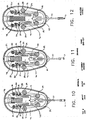
- Figure 12 is a section view taken along line 10-10 of Figure 9 illustrating the applier in its fired position.
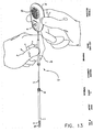
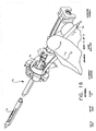
- Figure 13 is an isometric view of the applier of Figure 1 illustrated preoperatively where an alignment tool for the applier is being held above the egress tube.
- Figure 14 is an isometric view of a biopsy cannula of an instrument for taking a breast biopsy, where a portion of the biopsy cannula housing is broken away to better illustrate the insertion and orientation of the egress tube into the biopsy cannula.
- Figure 15 is an isometric view illustrating insertion of the egress tube into the biopsy cannula of Figure 14.
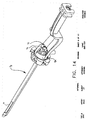
- Figure 16 is an isometric view illustrating the rotation of the alignment tool to align the alignment hub of the egress tube with the hub receiver of the biopsy cannula.
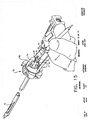
- Figure 17 is an isometric view of the applier having been aligned with the biopsy cannula of Figure 14.
- Figure 18 is an isometric view of the applier with the housing portion of the applier moved distally until the marker and its ferrule are adjacent the base of an egress ramp at the egress opening of the egress tube.
- Figure 19 is an enlarged isometric view of the distal portion of the egress tube of Figure 18.
- Figure 20 is an isometric view of the applier with the housing portion at its distal most position illustrating the ramped movement of the marker and its ferrule up the egress ramp of the egress tube.
- Figure 21 is an enlarged isometric view of the distal portion of the egress tube of Figure 20 where the marker is positioned for deployment.
- Figure 22 is a fragmentary distal end sectional view illustrating the plan view of the marker loaded within the applier in its original open configuration.
- Figure 23 is a fragmentary distal end sectional view illustrating the marker in its initial stage of ejection from the applier.
- Figure 24 is a fragmentary distal end sectional view illustrating the marker in a further stage of ejection from the applier.
- Figure 25 is a fragmentary distal end sectional view illustrating the marker in yet a further stage of ejection from the applier.
- Figure 26 is a fragmentary distal end sectional view illustrating the marker in a still further stage of ejection from the applier.
- Figure 27 is a fragmentary distal end sectional view illustrating the marker at a final stage of ejection just prior to release from the applier.
- Figure 28 is an enlarged isometric view of the distal portion of the egress tube after final deployment of the marker.
- the preferred applier 30 for delivering a marker to a biopsy site and subsequently deploying the marker at the site is illustrated in detail in Figures 1-9.
- the preferred marker 31 for the applier can best be seen in Figure 6. This marker is described in detail in copending European patent application No. filed contemporaneously herewith claiming priority from USSN 09/105,757 (attorney's Ref: P021669EP).
- the marker is held in its open position within a marker holder 32.
- the distal portion of the marker holder has a slot 33 for receiving the marker.
- a ferrule 34 receives the marker holder containing the marker.
- the proximal end of the ferrule abuts an abutment shoulder 35 on the marker holder, and a plurality of staked cleats 36 ensures secure attachment of the ferrule to the marker holder.
- the ferrule has a rolled distal edge forming surface 62 for reconfiguring the marker held in the marker holder from its original open configuration to a closed configuration once the marker has being properly delivered to, and positioned within, the biopsy site.
- the marker holder 32 is bonded to the distal end of an elongated flexible tube 37. Consequently, the ferrule is effectively secured to the distal end of the flexible tube.
- An elongated, push wire forming rod 38 is received in the flexible tube.
- the forming rod can slide inside the flexible tube and is adapted to reconfigure the marker housed in the marker slot within the ferrule from its original open position to its closed position.
- the forming rod is illustrated in an unactuated position within the flexible tube, spaced from the marker.
- the flexible tube has a flexible tube base 40 at its proximal end which is secured in a flexible tube cavity 41 within the housing.
- a slider 42 is received in the housing between a pair of slider tracks 43.
- the slider has a pair of spring arms 44, each of which includes a slider detent 45.
- the slider also includes a spring retainer 46 and an indicator tab 47.
- a spring 48 is seated on the spring retainer and abuts a spring base 49 in the housing when the slider is placed in the housing.
- a push wire retainer 51 crimps the proximal end of the elongated push wire forming rod 38 to secure the forming rod to the slider. Consequently, when the slider is actuated as illustrated in Figures 10-12, the forming rod moves distally as the slider moves distally so that the distal end of the forming rod engages the marker for reconfiguration of the marker from its original open position to its closed position.
- the release button 52 which is attached to the housing.
- the release button has four guide pins 53 which are received in four corresponding slide guides 54 in the housing.
- the release button also has a pair of firing posts 55, each of which includes a firing ramp 56 (see specifically Figure 3).
- the firing posts of the release button are adapted to contact the spring arms 44 of the slider 42 at the firing ramps when the release button is squeezed. Consequently, when the release button is squeezed, the firing ramps on the firing post of the button urge the spring arms of the slider inwardly as illustrated in Figure 11.
- the slider detents on the spring arms of the slider move past the slider locks 50 in the housing so that the spring force ofthe spring can urge the slider to move distally.
- the housing has a housing cover 57 to cover the contents within the housing.
- the housing cover has a plurality of assembly pins 58 which are received in corresponding assembly bosses 59 of the housing.
- the housing cover also has a button orifice 60 from which the release button protrudes when the housing cover is attached to the housing.
- the housing cover has a view port 61.
- the marker upon further distal movement of the forming rod, the marker is cammed against the distal edge forming surface 62 of the ferrule 34 for reconfiguration of the marker from its original open position to its closed position.
- the marker and the forming rod protrude form the distal end of the ferrule.
- the indicator tab 47 on the slider is consequently positioned so that it is observable through the view port 61 of the housing cover 57. This provides the user of the applier with a visual indication that the marker has been deployed.
- This visual indication coupled with tactile and audible sensations when the release button is squeezed, provides the user with an array of sensory perceptions to ensure that the marker has indeed been fired.
- the preferred applier of this invention has an egress tube 63 for receiving the distal end of the elongated flexible tube 37.
- the egress tube has an egress opening 64 at its distal end.
- the egress opening has an egress ramp 65.
- the egress tube has an alignment hub 66.
- the alignment hub has an alignment tab 67 at its distal end, and two pairs of hub tabs 68 at its proximal end.
- the applier has an alignment tool 68 mounted over the elongated flexible tube 37 for sliding and rotational movement between the housing 39 of the applier and the alignment hub 66 on the proximal end of the egress tube 63.
- the alignment tool has a driver tube 70 for manipulating the alignment tool, and a hub driver 71 affixed to the driver tube at the distal end of the driver tube.
- the hub driver has four driver tabs 72 at its distal end which are adapted to align with the hub tabs 68 on the proximal end of the alignment hub of the egress tube.
- Figures 13-27 illustrate how the applier is used to deliver the marker through a biopsy cannula of a biopsy instrument to a biopsy site for subsequent deployment of the marker at the site.
- the user initially threads a portion of the distal end of the flexible tube 37 through the egress tube 63.
- the reader should note that the alignment tool 69 is positioned around the proximal end of the flexible tube between the egress tube and the housing 39 of the applier.
- a conventional biopsy cannula 73 of a biopsy instrument which is used for extracting a tissue sample at a biopsy site is illustrated.
- the distal end of the biopsy cannula has an elongated biopsy port 74 which is adapted to receive the tissue sample.
- a biopsy cannula housing 99 Near the proximal end of the biopsy cannula, there is a biopsy cannula housing 99 (partially broken away for ease of illustration) which includes a hub receiver 75 for receiving the alignment hub of the egress tube of the applier. More particularly, the hub receiver has an alignment tab receiver 76 for receiving the alignment tab of the alignment hub.
- the user can then insert the egress tube of the applier through the hub receiver of the biopsy cannula.
- the alignment tool is then moved distally toward the alignment hub as illustrated in Figure 15.
- the driver tabs 72 of the hub driver on the driver tube of the alignment tool are mated with the corresponding hub tabs 68 on the alignment hub of the egress tube, the user can then rotate the driver tube to correspondingly rotate the alignment hub. Consequently, the egress tube is likewise rotated.
- the rotation of the egress tube is necessary because it is critical that the egress opening at the distal end of the egress tube is aligned in the same direction as the biopsy port of the biopsy cannula.
- the alignment hub is brought into proper alignment with the hub receiver when the alignment tab 67 is aligned with the alignment tab receiver 76 on the biopsy cannula.
- the user can then continue to insert the elongated flexible tube through the egress tube in the distal direction from the position designated as "L” in Figure 17 to the position designated as "l” in Figure 18.
- the ferrule 34 is positioned adjacent the egress ramp 65 when the elongated flexible tube is positioned as shown in Figure 18.
- FIGs 22-28 illustrate the sequence of steps as the push wire forming rod is moved from its unactuated position spaced from the marker to its fully actuated position where the forming rod and marker protrude from the distal end of the ferrule, and the marker has been reconfigured from its opened position to its closed position.
- the forming rod moves distally in response to squeezing of the release button, it contacts the bridge of the marker and urges the marker through the ferrule.
- the legs of the marker are cammed against the rolled distal edge forming surface 62 of the ferrule. This camming action urges the tips of the legs of the marker together for proper deployment of the marker.
Abstract
Description
- This invention relates to an applier for delivering and deploying a marker for implantation in tissue of a surgical patent. More specifically, it relates to such an applier for delivery and deployment of an implantable biopsy marker for defining particular locations in human tissue during a biopsy procedure, particularly in a human breast.
- One in nine American women will develop breast cancer in their lifetime. It is the leading cause of cancer deaths in women 40-55 years of age and the second leading cause of cancer deaths in women overall. Breast cancer will be diagnosed in approximately one in eight women in their lifetime, and one in 30 will die of this disease. Breast cancer does occur in males but is much less common. Biopsy requests stem from a screening process generally performed via a physical examination (palpable) and/or mammogram (non-palpable). A biopsy is indicated if suspicious tissue is detected. Five out of six biopsies performed return benign indications.
- It is desirable and often necessary to perform procedures for detecting, sampling, and testing lesions and other abnormalities in the tissue of humans and other animals, particularly in the diagnosis and treatment of patients with cancerous tumors, pre-malignant condition and other diseases or disorders. Typically, in the case of cancer, when a physician establish by means of known procedures (i.e. palpation, x-ray, MRI, or ultrasound imaging) that suspicious circumstances exist, a biopsy is performed to determine whether the cells are cancerous. Biopsy may be an open or percutaneous technique. Open biopsy removes the entire mass (excisional biopsy) or a part of the mass (incisional biopsy). Percutaneous biopsy on the other hand is usually done with a needle-like instrument and may be either a fine needle aspiration (FNA) or a core biopsy. In FNA biopsy, very small needles are used to obtain individual cells or clusters of cells for cytologic examination. The cells may be prepared such as in a Papanicolaou (Pap) smear. In core biopsy, as the term suggests, a core or fragment of tissue is obtained for histologic examination, which may be done via a frozen section or paraffin section. The chief difference between FNA and core biopsy is the size of the tissue sample taken. An imaging system having spectroscopic capabilities, such as the stereotactic guidance system described in U.S. Patent No. 5,240,011 is employed to guide the extraction instrument to the lesion.
- Depending on the procedure being performed, the sample may result in the suspicious lesion being partially or completely removed. Visibility of the lesion by the imaging system may be hampered because of the distortion created by the extraction process itself as well as associated bleeding in the surrounding tissues. Although the lesion is removed and all fluids are continuously aspirated from the extraction site, it is likely that the process will "cloud" the lesion, thus impairing exact recognition of its margins. This makes it difficult to ensure that the entire lesion will be removed.
- Often, the lesion is merely a calcification derived from dead abnormal tissue, which may be cancerous or pre-cancerous, and it is desirable to remove only a sample of the lesion, rather than the entire lesion, to evaluate it. This is because such a lesion actually serves to mark or define the location of adjacent abnormal tissue, so the physician does not wish to remove the entire lesion and thereby lose a critical means for later relocating the affected tissue. One of the benefits to the patient from core biopsy is that the mass of the tissue taken is small. However, oftentimes, either inadvertently or because the lesion is too small, the entire lesion is removed for evaluation, even though it is desirable to remove only a portion. Then, if subsequent analysis indicates the tissue to be malignant (malignant tissue requires removal, days or weeks later, of tissue around the immediate site of the original biopsy), it is difficult for the physician to determine the precise location of the lesion, in order to perform necessary additional procedures on adjacent potentially cancerous tissue. Additionally, even if the lesion is found to be benign, there will be no evidence of its location during future examinations, to mark the location of the previously removed calcification so that the affected tissue may be carefully monitored for future reoccurrence.
- Thus, it would be of considerable benefit to be able to permanently mark the location or margins of such a lesion prior to or immediately after removing the sample. Marking prior to removal would help to ensure that the entire lesion is excised, if desired. Alternatively, if the lesion were inadvertently removed in its entirety, marking the biopsy site immediately after the procedure would enable reestablishment of its location for future identification.
- A number of procedures and devices for marking and locating particular tissue locations are known in the prior art. For example, location wire guides, such as that described in U.S. Patent No. 5,221,269 to Miller et al, are well known for locating lesions, particularly in the breast. The device described by Miller comprises a tubular introducer needle and an attached wire guide, which has at its distal end a helical coil configuration for locking into position about the targeted lesion. The needle is introduced onto the breast and guided to the lesion site using an imaging system of a known type, for example, x-ray, ultrasound or magnetic resonance imaging (MRI), at which time the helical coil at the distal end is deployed about the lesion. Then, the needle may be removed from the wire guide, which remains in a locked position distally about the lesion for guiding a surgeon down the wire to the lesion site during subsequent surgery. While such a location system is effective, it is obviously intended and designed to be only temporary, and is removed once the surgery or other procedure has been completed.
- Other devices are known for marking external regions of a patient's skin. For example, U.S. Patent No. 5,192,270 to Carswell, Jr. discloses a syringe which dispenses a colorant to give a visual indication on the surface of the point at which an injection has or will be given. Similarly, U.S. Patent No. 5,147,307 to Gluck discloses a device which has patterning elements for impressing a temporary mark in a patients skin, for guiding the location of an injection or the like. It is also known to tape or otherwise adhere a small metallic marker, e.g. a 3 millimeter diameter lead sphere, on the skin of a human breast in order to delineate the location of skin calcifications (see Homer et al, The Geographic Cluster of Microcalcifications of the Breast, Surgery, Gynecology, & Obstetrics, December 1985). Obviously, however, none of these approaches are useful for marking and delineating internal tissue abnormalities, such as lesions or tumors.
- Still another approach for marking potential lesions and tumors of the breast is described in U.S. Patent No. 4,080,959. In the described procedure, the skin of the portion of the body to be evaluated, such as the breasts, is coated with a heat sensitive color-responsive chemical, after which that portion of the body is heated with penetrating radiation such as diathermy. Then, the coated body portion is scanned for color changes which would indicate hot spots beneath the skin surface. These so-called hot spots may represent a tumor or lesion, which does not dissipate heat as rapidly because of its relatively poor blood circulation (about 1/20 of the blood flow through normal body tissue). This method, of course, functions as a temporary diagnostic tool, rather than in a permanent means for delineating the location of a tumor or lesion.
- A method of identifying and treating abnormal neoplastic tissue or pathogens within the body is described in U.S. Patent No. 4,649,151 to Doughety et al. In this method, a tumor-selective photosensitizing drug is introduced into a patient's body, where it is cleared from normal tissue faster than it is cleared from abnormal tissue. After the drug clears normal tissue but before it has cleared abnormal neoplastic tissue, the abnormal neoplastic tissue may be located by the luminescence of the drug within the abnormal tissue. The fluorescence may be observed with low intensity light, some of which is within the drug's absorbency spectrum. Once detected, the tissue may be destroyed by further application of higher intensity light having a frequency within the absorbency spectrum of the drug. Of course, this method also is only a temporary means for marking the abnormal tissue. Additionally, once the abnormal tissue has been destroyed during treatment, the marker is destroyed as well.
- It is also known to employ biocompatible dyes or stains to mark breast lesions. First, a syringe containing the colorant is guided to a detected lesion, using an imaging system. Later, during the extraction procedure, the surgeon harvests a tissue sample from the stained tissue. However, while such staining techniques can be effective, it is difficult to precisely localize the stain. Also, the stains are difficult to detect flouoroscopically and may not always be permanent.
- Additionally, it is known to implant markers directly into a patient's body using invasive surgical techniques. For example, during a coronary artery bypass graft (CABG), which of course constitutes open-heart surgery, it is common practice to surgically apply one or more metallic rings to the aorta at the site of the graft. This enables a practitioner to later return to the site of the graft by identifying the rings, for evaluative purposes. It is also common practice to mark a surgical site with staples, vascular clips, and the like, for the purpose of future evaluation of the site.
- A technique has been described for the study of pharyngeal swallowing in dogs, which involves permanently implanting steel marker beads in the submucosa of the pharynx (S.S. Kramer et al, A Permanent Radiopaque Marker Technique for the Study of Pharyngeal Swallowing of Dogs, Dysphagia, Vol. 1, pp.163-167, 1987). The article posits that the radiographic study of these marker beads during swallowing on many occasions over a substantial period of time provides a better understanding of the pharyngeal phase of deglutition on humans. In the described technique, the beads were deposited using a metallic needle cannula having an internal diameter slightly smaller than the beads to be implanted. When suction was applied to the cannula, the bead sat firmly on the tip. Once the ball-tipped cannula was inserted through tissue, the suction was broken, thereby releasing the bead, and the cannula is withdrawn.
- Of course, this technique was not adapted or intended to mark specific tissue sites, but rather to mark an entire region or structure of the body in order to evaluate anatomical movements (i.e. swallowing motions). It also was not intended for use in humans.
- Accordingly, what is needed is a method and device for non-surgically implanting potentially permanent markers at the site of a lesion or other abnormal tissue, for the purpose of defining the margins of a lesion before it is removed and/or to establish its location after it has been removed. The markers should be easy to deploy and easily detected using state of the art imaging techniques.
- A method of implanting markers directly into a patient's body using minimally invasive surgical techniques is described in International Patent No. WO 9608208A1 to Foerster et al. In this method, a clipping device is introduced to the lesion site by a tubular cannula. Once the clip is at the lesion site, an actuating means at the proximal end outside the patient deploys the clip into the tissue. This marking means can be used long term and can be imaged by most imaging techniques. However, because of it's small size, current ultrasound imaging systems are unable to detect is within the tissue.
- Another method of implanting a marker is described in copending, commonly assigned application Serial No. 08/802,958, filed February 21, 1997, and entitled "Apparatus and Method for Marking Tissue". The marker described in this method utilizes a central tang that is tensily loaded to cause a squarely supported, end contact bridge on the marker to bend resulting in the goal post arms to swing inward in an arcuate fashion to pinch tissue. The tensile load on the tang is increased until it breaks at a predetermined location leaving the marker attached to the tissue site. Unfortunately, this method requires the marker to be pulled away from tissue when the marker is formed, consequently, limiting marker penetration and the amount of tissue grasped. Additionally, the marker is delivered to the biopsy site when the marker applier is correspondingly delivered through the biopsy cannula which is used for taking the biopsy sample. It is necessary to properly orient the opening on the applier with the biopsy port on the biopsy cannula in order to properly deploy the marker at the biopsy site. Unfortunately, the method described in this pending application does not describe a technique for readily accomplishing the proper orientational alignment between the applier opening and the biopsy port.
- A surgical clip for permanently joining opposed tissue for an anastomosis procedure is described in U. S. Patent No. 4,733,664 to Kirsh et al. This is accomplished using an applier, also disclosed, to pull on a frangible central tang to close a pair of spaced arcuate arms extending generally parallel in one direction from opposite ends of the plastically deformable bridge. The arms are brought around opposed tissue. A predetermined force is applied to create a tensile break of the neck in the tang. Specific angles of clip shoulder and applier are given. The applier jaw faces are in the range of 120° to 180° with respect to one another, specifically 150° Unfortunately, the method of forming this clip suffers a fate similar to the method described in the preceding paragraph.
- Accordingly, what is needed is an applier for delivering a biopsy marker to a site of a surgical biopsy, and deploying the marker at the site. The applier should be capable of forming the marker from an original open configuration to a closed configuration at the biopsy site. It should be able to accomplish this forming function simply and reliably. Additionally, the applier should be capable of readily aligning the opening in the applier which delivers the marker with the biopsy port of the biopsy cannula which takes the biopsy sample to ensure proper deployment of the marker.
- The invention is an applier for initially delivering a biopsy marker to a surgical biopsy site and subsequently deploying the marker at the site. The applier comprises an elongated flexible tube having a distal end, a ferrule fixed to the distal end of the flexible tube, a marker holder at the ferrule for holding the biopsy marker at the distal end of the flexible tube in the original open position, an elongated forming rod, and an egress tube for receiving the distal end of the elongated flexible tube.
- The ferrule of the applier has a forming surface on it adapted to reconfigure the biopsy marker from an original open configuration to a closed configuration when the biopsy marker has been delivered to the surgical site.
- The elongated forming rod in the flexible tube is adapted to urge the biopsy marker into reconfiguring contact with the forming surface of the ferrule. The forming rod is slidable in the flexible tube from an unactuated position where the biopsy marker is in the original open position to an actuated position where the biopsy marker has been reconfigured in the closed position (and consequently deployed at the surgical site).
- The egress tube of the applier is adapted for delivery through a biopsy cannula. The biopsy cannula has a biopsy port at its distal end. During a biopsy, the biopsy port of the biopsy cannula is positioned at the biopsy site so that a biopsy sample can be captured in the port. The egress tube has proximal and distal ends. The egress tube has an egress opening at the distal end of the egress tube. It also has an alignment hub at its proximal end. The alignment hub is adapted for orientational alignment with a hub receiver on the biopsy cannula. The alignment of the alignment hub and the hub receiver causes the alignment of the egress opening of the egress tube with the biopsy port of the biopsy cannula.
- The applier of this invention delivers a biopsy marker to a site of a surgical biopsy, and deploys the marker at the site. The applier readily forms the marker from an original open configuration to a closed configuration at the biopsy site. This is accomplished by using the forming rod to urge the marker held in the marker holder into reconfiguring contact with the forming surface of the ferrule. Consequently, marker formation is accomplished simply and reliably.
- Significantly, the egress opening of the egress tube of the applier of this invention can be readily aligned with a biopsy port of a biopsy cannula. The marker is delivered through the egress opening of the egress tube when the distal end of the elongated flexible tube is delivered through the egress tube. The biopsy sample is taken with the biopsy cannula when the biopsy port is positioned at the biopsy site. When the egress opening of the egress tube and the biopsy port of the biopsy cannula are orientationally aligned in the same direction, the marker can be properly delivered through the egress opening and into the biopsy port of the biopsy cannula. When the marker is delivered into the biopsy port, proper delivery of the marker to the biopsy site has been established, and proper deployment of the marker at the site can accordingly be accomplished. The incorporation of the alignment hub at the proximal end of the egress tube for orientation alignment with a hub receiver on the biopsy cannula provides a simple mechanism to insure proper alignment and thus proper delivery and deployment of the marker at the site.
- The applier of this invention can be used in any biopsy procedure where it is necessary or desirable to deliver and deploy a marker at a biopsy site. The applier can be used to deliver and deploy a marker during an endoscopic surgical procedure, or a conventional open surgical procedure as well.
- Figure 1 is and isometric view of an applier for a marker constructed in accordance with a preferred embodiment of this invention.
- Figure 2 is an exploded isometric view of the applier of Figure 1.
- Figure 3 is an exploded isometric view of the housing portion of the applier of Figure 1.
- Figure 4 is a rear elevational view of a slider contained in the housing portion of the applier of Figure 1 for actuating the forming rod.
- Figure 5 is an enlarged and foreshortened isometric view of the distal end of the applier of Figure 1.
- Figure 6 is an enlarged and exploded isometric view of the distal end of the applier of Figure 1.
- Figure 7 is a longitudinal section view through the distal end portion of the applier of Figure 1.
- Figure 8 is an enlarged view of the distal end portion of the applier of Figure 1.
- Figure 9 is an enlarged partially assembled isometric view of the housing portion of the applier of Figure 1.
- Figure 10 is a section view taken along line 10-10 of Figure 9 illustrating the applier in its pre-fire position.
- Figure 11 is a section view taken along line 10-10 of Figure 9 illustrating the applier at an intermediate point between its pre-fired and fired positions.
- Figure 12 is a section view taken along line 10-10 of Figure 9 illustrating the applier in its fired position.
- Figure 13 is an isometric view of the applier of Figure 1 illustrated preoperatively where an alignment tool for the applier is being held above the egress tube.
- Figure 14 is an isometric view of a biopsy cannula of an instrument for taking a breast biopsy, where a portion of the biopsy cannula housing is broken away to better illustrate the insertion and orientation of the egress tube into the biopsy cannula.
- Figure 15 is an isometric view illustrating insertion of the egress tube into the biopsy cannula of Figure 14.
- Figure 16 is an isometric view illustrating the rotation of the alignment tool to align the alignment hub of the egress tube with the hub receiver of the biopsy cannula.
- Figure 17 is an isometric view of the applier having been aligned with the biopsy cannula of Figure 14.
- Figure 18 is an isometric view of the applier with the housing portion of the applier moved distally until the marker and its ferrule are adjacent the base of an egress ramp at the egress opening of the egress tube.
- Figure 19 is an enlarged isometric view of the distal portion of the egress tube of Figure 18.
- Figure 20 is an isometric view of the applier with the housing portion at its distal most position illustrating the ramped movement of the marker and its ferrule up the egress ramp of the egress tube.
- Figure 21 is an enlarged isometric view of the distal portion of the egress tube of Figure 20 where the marker is positioned for deployment.
- Figure 22 is a fragmentary distal end sectional view illustrating the plan view of the marker loaded within the applier in its original open configuration.
- Figure 23 is a fragmentary distal end sectional view illustrating the marker in its initial stage of ejection from the applier.
- Figure 24 is a fragmentary distal end sectional view illustrating the marker in a further stage of ejection from the applier.
- Figure 25 is a fragmentary distal end sectional view illustrating the marker in yet a further stage of ejection from the applier.
- Figure 26 is a fragmentary distal end sectional view illustrating the marker in a still further stage of ejection from the applier.
- Figure 27 is a fragmentary distal end sectional view illustrating the marker at a final stage of ejection just prior to release from the applier.
- Figure 28 is an enlarged isometric view of the distal portion of the egress tube after final deployment of the marker.
- The
preferred applier 30 for delivering a marker to a biopsy site and subsequently deploying the marker at the site is illustrated in detail in Figures 1-9. Thepreferred marker 31 for the applier can best be seen in Figure 6. This marker is described in detail in copending European patent application No. filed contemporaneously herewith claiming priority from USSN 09/105,757 (attorney's Ref: P021669EP). - As illustrated in Figure 6, and further aided with Figures 7 and 8, the marker is held in its open position within a
marker holder 32. The distal portion of the marker holder has aslot 33 for receiving the marker. Aferrule 34 receives the marker holder containing the marker. The proximal end of the ferrule abuts anabutment shoulder 35 on the marker holder, and a plurality of stakedcleats 36 ensures secure attachment of the ferrule to the marker holder. As illustrated specifically in Figure 8, the ferrule has a rolled distaledge forming surface 62 for reconfiguring the marker held in the marker holder from its original open configuration to a closed configuration once the marker has being properly delivered to, and positioned within, the biopsy site. - As illustrated in Figures 2, 6, 7 and 8, the
marker holder 32 is bonded to the distal end of an elongatedflexible tube 37. Consequently, the ferrule is effectively secured to the distal end of the flexible tube. An elongated, pushwire forming rod 38 is received in the flexible tube. The forming rod can slide inside the flexible tube and is adapted to reconfigure the marker housed in the marker slot within the ferrule from its original open position to its closed position. In Figures 7 and 8, the forming rod is illustrated in an unactuated position within the flexible tube, spaced from the marker. - Referring now to Figures 2-4 and 9, the reader will observe that the elongated
flexible tube 37 is attached to ahousing 39. The flexible tube has aflexible tube base 40 at its proximal end which is secured in aflexible tube cavity 41 within the housing. Aslider 42 is received in the housing between a pair of slider tracks 43. The slider has a pair ofspring arms 44, each of which includes aslider detent 45. The slider also includes aspring retainer 46 and anindicator tab 47. Aspring 48 is seated on the spring retainer and abuts aspring base 49 in the housing when the slider is placed in the housing. - Continuing to refer to Figures 2-4 and 9, and further observing Figures 10-12, when the
slider 42 is positioned between the slider tracks 43 of the housing, the pair ofslider detents 45 on thespring arms 44 of the slider rest on a pair of corresponding slide locks 50 contained in the housing. In its unfired position (Figure 10), the slide locks hold the slider in a proximal position, and the spring is compressed. When the slider is actuated (Figures 11 and 12), the slider detents of the spring arms move past the slide locks in the housing, and the slider consequently moves distally as a result of the spring force of the spring. - As illustrated in Figure 4, a push wire retainer 51 crimps the proximal end of the elongated push
wire forming rod 38 to secure the forming rod to the slider. Consequently, when the slider is actuated as illustrated in Figures 10-12, the forming rod moves distally as the slider moves distally so that the distal end of the forming rod engages the marker for reconfiguration of the marker from its original open position to its closed position. - Referring now to Figures 2, 3, and 9, the reader will observe a
release button 52 which is attached to the housing. The release button has fourguide pins 53 which are received in four corresponding slide guides 54 in the housing. The release button also has a pair of firingposts 55, each of which includes a firing ramp 56 (see specifically Figure 3). The firing posts of the release button are adapted to contact thespring arms 44 of theslider 42 at the firing ramps when the release button is squeezed. Consequently, when the release button is squeezed, the firing ramps on the firing post of the button urge the spring arms of the slider inwardly as illustrated in Figure 11. As a result of this inward movement, the slider detents on the spring arms of the slider move past the slider locks 50 in the housing so that the spring force ofthe spring can urge the slider to move distally. - As illustrated in Figures 2 and 3, the housing has a
housing cover 57 to cover the contents within the housing. The housing cover has a plurality of assembly pins 58 which are received incorresponding assembly bosses 59 of the housing. The housing cover also has a button orifice 60 from which the release button protrudes when the housing cover is attached to the housing. Finally, the housing cover has aview port 61. - Referring once again to Figures 10-12, when the
slider 42 is in its unfired position, therelease button 52 on the housing of the applier has not yet been squeezed, and the pushwire forming rod 38 is in its unactuated position spaced from the marker. When the button is squeezed, the slider moves distally from its unfired position to its fired position. Since the proximal end of the push wire forming rod is attached to the slider, the forming rod moves from its unactuated position to its actuated position when the slider moves from its unfired position to its fired position. When the forming rod moves distally within theflexible tube 37 of the applier, it moves through themarker holder 32 and makes contact with themarker 31. Consequently, upon further distal movement of the forming rod, the marker is cammed against the distaledge forming surface 62 of theferrule 34 for reconfiguration of the marker from its original open position to its closed position. As seen in Figure 12, upon complete firing of the marker, the marker and the forming rod protrude form the distal end of the ferrule. Additionally, when the button is squeezed and the slider has moved to the fired position, theindicator tab 47 on the slider is consequently positioned so that it is observable through theview port 61 of thehousing cover 57. This provides the user of the applier with a visual indication that the marker has been deployed. This visual indication, coupled with tactile and audible sensations when the release button is squeezed, provides the user with an array of sensory perceptions to ensure that the marker has indeed been fired. - Referring now to Figures 2, 5, 7 and 8, the preferred applier of this invention has an
egress tube 63 for receiving the distal end of the elongatedflexible tube 37. The egress tube has anegress opening 64 at its distal end. The egress opening has anegress ramp 65. At its proximal end, the egress tube has analignment hub 66. The alignment hub has analignment tab 67 at its distal end, and two pairs ofhub tabs 68 at its proximal end. - In a particularly preferred embodiment of the applier of this invention, the applier has an
alignment tool 68 mounted over the elongatedflexible tube 37 for sliding and rotational movement between thehousing 39 of the applier and thealignment hub 66 on the proximal end of theegress tube 63. The alignment tool has adriver tube 70 for manipulating the alignment tool, and ahub driver 71 affixed to the driver tube at the distal end of the driver tube. The hub driver has fourdriver tabs 72 at its distal end which are adapted to align with thehub tabs 68 on the proximal end of the alignment hub of the egress tube. - We will now turn to Figures 13-27, which illustrate how the applier is used to deliver the marker through a biopsy cannula of a biopsy instrument to a biopsy site for subsequent deployment of the marker at the site. As illustrated specifically in Figure 13, the user initially threads a portion of the distal end of the
flexible tube 37 through theegress tube 63. The reader should note that thealignment tool 69 is positioned around the proximal end of the flexible tube between the egress tube and thehousing 39 of the applier. - In Figure 14, a
conventional biopsy cannula 73 of a biopsy instrument which is used for extracting a tissue sample at a biopsy site is illustrated. The distal end of the biopsy cannula has an elongatedbiopsy port 74 which is adapted to receive the tissue sample. Near the proximal end of the biopsy cannula, there is a biopsy cannula housing 99 (partially broken away for ease of illustration) which includes ahub receiver 75 for receiving the alignment hub of the egress tube of the applier. More particularly, the hub receiver has analignment tab receiver 76 for receiving the alignment tab of the alignment hub. - Referring now to Figures 15-18, once a portion of the distal end of the elongated flexible tube is threaded into the egress tube, the user can then insert the egress tube of the applier through the hub receiver of the biopsy cannula. When the
alignment hub 66 of the egress tube abuts the hub receiver, the alignment tool is then moved distally toward the alignment hub as illustrated in Figure 15. When thedriver tabs 72 of the hub driver on the driver tube of the alignment tool are mated with the correspondinghub tabs 68 on the alignment hub of the egress tube, the user can then rotate the driver tube to correspondingly rotate the alignment hub. Consequently, the egress tube is likewise rotated. The rotation of the egress tube is necessary because it is critical that the egress opening at the distal end of the egress tube is aligned in the same direction as the biopsy port of the biopsy cannula. As the user rotates the driver tube of the alignment tool, the alignment hub is brought into proper alignment with the hub receiver when thealignment tab 67 is aligned with thealignment tab receiver 76 on the biopsy cannula. When this alignment is achieved, proper alignment of theegress opening 64 at the distal end of the egress tub with thebiopsy port 74 of the biopsy cannula is assured. Once proper alignment is accomplished with the alignment tool, the user can then continue to insert the elongated flexible tube through the egress tube in the distal direction from the position designated as "L" in Figure 17 to the position designated as "ℓ" in Figure 18. As illustrated in Figure 19, theferrule 34 is positioned adjacent theegress ramp 65 when the elongated flexible tube is positioned as shown in Figure 18. - As illustrated in Figures 20 and 21, when the user has moved the flexible tube distally so that the housing abuts the proximal end of the
driver tube 70, theferrule 34 has slid on the egress ramp so that the distal end of the flexible tube protrudes from the distal end of the egress tube for proper delivery and positioning at the biopsy site. - Once the marker is properly positioned where the ferrule of the applier protrudes from the distal end of the egress tube, and accordingly from the biopsy port of the biopsy cannula as well, the marker has now been delivered and properly positioned at the biopsy site. Figures 22-28 illustrate the sequence of steps as the push wire forming rod is moved from its unactuated position spaced from the marker to its fully actuated position where the forming rod and marker protrude from the distal end of the ferrule, and the marker has been reconfigured from its opened position to its closed position. As the forming rod moves distally in response to squeezing of the release button, it contacts the bridge of the marker and urges the marker through the ferrule. As the marker is urged through the ferrule, the legs of the marker are cammed against the rolled distal
edge forming surface 62 of the ferrule. This camming action urges the tips of the legs of the marker together for proper deployment of the marker. - Although this invention has been described in connection with its most preferred embodiment, numerous additional embodiments will become apparent to those skilled in this art. Accordingly, the reader should refer to the claims which appear below to understand the full scope and spirit of the claimed invention. The most preferred embodiment of this invention is intended solely to provide an example of the invention and not to limit the scope of the claimed invention.
Claims (8)
- An applier for initially delivering a biopsy marker to a surgical biopsy site and subsequently deploying said marker at the site, said applier comprising:a) an elongated flexible tube having a distal end;b) a ferrule fixed to the distal end of said flexible tube, said ferrule having a forming surface thereon adapted to reconfigure said biopsy marker from an original open configuration to a closed configuration when said biopsy marker has been delivered to the surgical site;c) a marker holder at said ferrule for holding said biopsy marker at the distal end of said flexible tube in the original open position;d) an elongated forming rod located in said flexible tube, said forming rod adapted to urge said biopsy marker into reconfiguring contact with said forming surface of said ferrule, said forming rod slidable in said flexible tube from an unactuated position wherein said biopsy marker is in the original open position to an actuated position wherein said biopsy marker has been reconfigured in the closed position;e) an egress tube for receiving the distal end of said elongated flexible tube, said egress tube adapted for delivery through a biopsy cannula wherein said cannula has a biopsy port at a distal end thereof for positioning at the surgical biopsy site to take a biopsy sample, said egress tube having proximal and distal ends, said egress tube having an egress opening at the distal end of said egress tube and an alignment hub at the proximal end of said egress tube, said alignment hub adapted for orientational alignment with a hub receiver on said biopsy cannula so as to align said egress opening of said egress tube with said biopsy port of said biopsy cannula.
- The applier of Claim 1 wherein said elongated flexible tube has a proximal end, and further comprising a housing fixed to the proximal end of said flexible tube.
- The applier of Claim 2 further comprising an alignment tool mounted over said flexible tube for sliding and rotational movement between said housing and said alignment hub on said egress tube.
- The applier of Claim 3 wherein said alignment tool has a driver tube and a hub driver on a distal end of said driver tube, said hub driver capable of being coupled to said alignment hub of said egress tube, and said alignment hub is rotated for orientational alignment with said hub receiver on said biopsy cannula when said hub driver is coupled to said alignment hub and said driver tube is rotated.
- The applier of Claim 1 wherein said marker holder has a marker slot thereon for receiving said biopsy marker.
- The applier of Claim 2 wherein said housing contains a slider therein coupled to a proximal end of said forming rod, said slider movable from an unfired position to a fired position, and when said slider is moved from the unfired position to the fired position, said forming rod is moved from the unactuated position to the actuated position.
- The applier of Claim 6 wherein said housing has a housing cover covering said slider, said housing having a release button protruding from said housing cover, and when said release button is squeezed, said slider is triggered so as to move from the unfired position to the fired position.
- The applier of Claim 7 wherein said slider has an indicator tab, and said housing cover has a view port, and when said slider has moved to the fired position, said indicator tab is observable through said view port of said housing cover.
Applications Claiming Priority (2)
| Application Number | Priority Date | Filing Date | Title |
|---|---|---|---|
| US09/105,570 US6261302B1 (en) | 1998-06-26 | 1998-06-26 | Applier for implantable surgical marker |
| US105570 | 1998-06-26 |
Publications (2)
| Publication Number | Publication Date |
|---|---|
| EP0966925A1 true EP0966925A1 (en) | 1999-12-29 |
| EP0966925B1 EP0966925B1 (en) | 2003-04-02 |
Family
ID=22306566
Family Applications (1)
| Application Number | Title | Priority Date | Filing Date |
|---|---|---|---|
| EP99305023A Expired - Lifetime EP0966925B1 (en) | 1998-06-26 | 1999-06-25 | Applier for implantable surgical marker |
Country Status (7)
| Country | Link |
|---|---|
| US (1) | US6261302B1 (en) |
| EP (1) | EP0966925B1 (en) |
| JP (1) | JP4472052B2 (en) |
| AU (1) | AU760565B2 (en) |
| CA (1) | CA2276788C (en) |
| DE (1) | DE69906420T2 (en) |
| ES (1) | ES2195518T3 (en) |
Cited By (9)
| Publication number | Priority date | Publication date | Assignee | Title |
|---|---|---|---|---|
| WO2003011161A1 (en) * | 2001-08-03 | 2003-02-13 | Tyco Healthcare Group Lp | Tissue marking apparatus and method |
| WO2005063126A2 (en) * | 2003-12-23 | 2005-07-14 | Senorx, Inc. | Biopsy device with aperture orientation and improved tip |
| WO2006017400A2 (en) * | 2004-08-03 | 2006-02-16 | Senorx, Inc. | Biopsy device with selectable tissue receiving aperture orientation and site illumination |
| EP1688100A1 (en) * | 2005-02-03 | 2006-08-09 | Inrad, Inc. | Apparatus for subcutaneous placement of an imaging marker |
| US7189206B2 (en) | 2003-02-24 | 2007-03-13 | Senorx, Inc. | Biopsy device with inner cutter |
| US7981051B2 (en) | 2005-08-05 | 2011-07-19 | Senorx, Inc. | Biopsy device with fluid delivery to tissue specimens |
| US8915864B2 (en) | 2005-08-05 | 2014-12-23 | Senorx, Inc. | Biopsy device with fluid delivery to tissue specimens |
| US9750487B2 (en) | 2005-05-23 | 2017-09-05 | Senorx, Inc. | Tissue cutting member for a biopsy device |
| US10105125B2 (en) | 2004-12-16 | 2018-10-23 | Senorx, Inc. | Biopsy device with aperture orientation and improved tip |
Families Citing this family (248)
| Publication number | Priority date | Publication date | Assignee | Title |
|---|---|---|---|---|
| US8668737B2 (en) | 1997-10-10 | 2014-03-11 | Senorx, Inc. | Tissue marking implant |
| US7637948B2 (en) | 1997-10-10 | 2009-12-29 | Senorx, Inc. | Tissue marking implant |
| US6347241B2 (en) * | 1999-02-02 | 2002-02-12 | Senorx, Inc. | Ultrasonic and x-ray detectable biopsy site marker and apparatus for applying it |
| US6161034A (en) * | 1999-02-02 | 2000-12-12 | Senorx, Inc. | Methods and chemical preparations for time-limited marking of biopsy sites |
| US20080146965A1 (en) | 2003-08-11 | 2008-06-19 | Salvatore Privitera | Surgical Device for The Collection of Soft Tissue |
| US20010047183A1 (en) * | 2000-04-05 | 2001-11-29 | Salvatore Privitera | Surgical device for the collection of soft tissue |
| US9820824B2 (en) | 1999-02-02 | 2017-11-21 | Senorx, Inc. | Deployment of polysaccharide markers for treating a site within a patent |
| US20090030309A1 (en) * | 2007-07-26 | 2009-01-29 | Senorx, Inc. | Deployment of polysaccharide markers |
| US8498693B2 (en) | 1999-02-02 | 2013-07-30 | Senorx, Inc. | Intracorporeal marker and marker delivery device |
| US7983734B2 (en) | 2003-05-23 | 2011-07-19 | Senorx, Inc. | Fibrous marker and intracorporeal delivery thereof |
| US8361082B2 (en) | 1999-02-02 | 2013-01-29 | Senorx, Inc. | Marker delivery device with releasable plug |
| US6725083B1 (en) * | 1999-02-02 | 2004-04-20 | Senorx, Inc. | Tissue site markers for in VIVO imaging |
| US7651505B2 (en) | 2002-06-17 | 2010-01-26 | Senorx, Inc. | Plugged tip delivery for marker placement |
| US20080039819A1 (en) * | 2006-08-04 | 2008-02-14 | Senorx, Inc. | Marker formed of starch or other suitable polysaccharide |
| US6862470B2 (en) | 1999-02-02 | 2005-03-01 | Senorx, Inc. | Cavity-filling biopsy site markers |
| US6086544A (en) | 1999-03-31 | 2000-07-11 | Ethicon Endo-Surgery, Inc. | Control apparatus for an automated surgical biopsy device |
| US6575991B1 (en) | 1999-06-17 | 2003-06-10 | Inrad, Inc. | Apparatus for the percutaneous marking of a lesion |
| GB2361544B (en) * | 2000-04-20 | 2004-07-07 | Goring Kerr Ltd | Metal detector |
| WO2002069808A2 (en) | 2000-11-06 | 2002-09-12 | Suros Surgical Systems, Inc. | Biopsy apparatus |
| US6758824B1 (en) * | 2000-11-06 | 2004-07-06 | Suros Surgical Systems, Inc. | Biopsy apparatus |
| CA2659518A1 (en) | 2000-11-20 | 2002-05-30 | Senorx, Inc. | Tissue site markers for in vivo imaging |
| US6592549B2 (en) * | 2001-03-14 | 2003-07-15 | Scimed Life Systems, Inc. | Rapid exchange stent delivery system and associated components |
| US6605047B2 (en) * | 2001-09-10 | 2003-08-12 | Vivant Medical, Inc. | Biopsy marker delivery system |
| US20030225420A1 (en) | 2002-03-11 | 2003-12-04 | Wardle John L. | Surgical coils and methods of deploying |
| EP1482841B1 (en) | 2002-03-14 | 2005-12-07 | Yeung, Jeffery E. | Suture anchor and approximating device |
| ES2360938T3 (en) * | 2002-04-17 | 2011-06-10 | Tyco Healthcare Group Lp | SEWING TOOL. |
| US7229452B2 (en) * | 2002-04-22 | 2007-06-12 | Tyco Healthcare Group Lp | Tack and tack applier |
| DE60318595T2 (en) * | 2002-08-01 | 2009-01-08 | James E. Birmingham Selis | biopsy devices |
| US20060036158A1 (en) | 2003-11-17 | 2006-02-16 | Inrad, Inc. | Self-contained, self-piercing, side-expelling marking apparatus |
| CA2505961C (en) * | 2002-11-18 | 2011-10-11 | Inrad, Inc. | Apparatus for implanting a preloaded localization wire |
| EP1608272B1 (en) | 2003-03-11 | 2017-01-25 | Covidien LP | Clip applying apparatus with angled jaw |
| US7877133B2 (en) | 2003-05-23 | 2011-01-25 | Senorx, Inc. | Marker or filler forming fluid |
| EP2314241B1 (en) | 2003-06-13 | 2013-08-07 | Covidien LP | Multiple member interconnect for surgical instrument and absorbable screw fastener |
| US7537788B2 (en) * | 2003-07-25 | 2009-05-26 | Rubicor Medical, Inc. | Post-biopsy cavity treatment implants and methods |
| US7001341B2 (en) * | 2003-08-13 | 2006-02-21 | Scimed Life Systems, Inc. | Marking biopsy sites |
| US20050273002A1 (en) | 2004-06-04 | 2005-12-08 | Goosen Ryan L | Multi-mode imaging marker |
| US20050143650A1 (en) * | 2003-11-26 | 2005-06-30 | Axel Winkel | Tissue marker and method and apparatus for deploying the marker |
| US20050234336A1 (en) * | 2004-03-26 | 2005-10-20 | Beckman Andrew T | Apparatus and method for marking tissue |
| US7465279B2 (en) * | 2004-03-31 | 2008-12-16 | Ethicon Endo-Surgery, Inc. | Marker device and method of deploying a cavity marker using a surgical biopsy device |
| US10478179B2 (en) | 2004-04-27 | 2019-11-19 | Covidien Lp | Absorbable fastener for hernia mesh fixation |
| US8075568B2 (en) * | 2004-06-11 | 2011-12-13 | Selis James E | Biopsy devices and methods |
| JP4833988B2 (en) | 2004-10-08 | 2011-12-07 | タイコ ヘルスケア グループ リミテッド パートナーシップ | Endoscopic surgical clip applier |
| US7819886B2 (en) | 2004-10-08 | 2010-10-26 | Tyco Healthcare Group Lp | Endoscopic surgical clip applier |
| US8409222B2 (en) | 2004-10-08 | 2013-04-02 | Covidien Lp | Endoscopic surgical clip applier |
| AU2005294178B2 (en) | 2004-10-08 | 2009-06-11 | Covidien Lp | Apparatus for applying surgical clips |
| US9763668B2 (en) | 2004-10-08 | 2017-09-19 | Covidien Lp | Endoscopic surgical clip applier |
| US8442623B2 (en) * | 2004-10-13 | 2013-05-14 | Suros Surgical Systems, Inc. | Site marker visible under multiple modalities |
| US20060079805A1 (en) * | 2004-10-13 | 2006-04-13 | Miller Michael E | Site marker visable under multiple modalities |
| US8060183B2 (en) | 2004-10-13 | 2011-11-15 | Suros Surgical Systems, Inc. | Site marker visible under multiple modalities |
| US8280486B2 (en) | 2004-10-13 | 2012-10-02 | Suros Surgical Systems, Inc. | Site marker visable under multiple modalities |
| US8409111B2 (en) | 2004-11-22 | 2013-04-02 | Bard Peripheral Vascular, Inc. | Removable localizing wire |
| US8419656B2 (en) * | 2004-11-22 | 2013-04-16 | Bard Peripheral Vascular, Inc. | Post decompression marker introducer system |
| US7731705B2 (en) | 2005-01-10 | 2010-06-08 | Wardle John L | Eluting coils and methods of deploying and retrieving |
| US7689227B2 (en) * | 2005-03-02 | 2010-03-30 | Qualcomm Incorporated | Method and apparatus for hashing over multiple frequency bands in a communication system |
| US20060270911A1 (en) * | 2005-04-08 | 2006-11-30 | Voegele James W | Tissue retraction device |
| US10357328B2 (en) | 2005-04-20 | 2019-07-23 | Bard Peripheral Vascular, Inc. and Bard Shannon Limited | Marking device with retractable cannula |
| US7909836B2 (en) | 2005-05-20 | 2011-03-22 | Neotract, Inc. | Multi-actuating trigger anchor delivery system |
| US8394113B2 (en) | 2005-05-20 | 2013-03-12 | Neotract, Inc. | Coiled anchor device |
| US8628542B2 (en) | 2005-05-20 | 2014-01-14 | Neotract, Inc. | Median lobe destruction apparatus and method |
| US9149266B2 (en) | 2005-05-20 | 2015-10-06 | Neotract, Inc. | Deforming anchor device |
| US9549739B2 (en) | 2005-05-20 | 2017-01-24 | Neotract, Inc. | Devices, systems and methods for treating benign prostatic hyperplasia and other conditions |
| US7896891B2 (en) * | 2005-05-20 | 2011-03-01 | Neotract, Inc. | Apparatus and method for manipulating or retracting tissue and anatomical structure |
| US8491606B2 (en) | 2005-05-20 | 2013-07-23 | Neotract, Inc. | Median lobe retraction apparatus and method |
| US7758594B2 (en) | 2005-05-20 | 2010-07-20 | Neotract, Inc. | Devices, systems and methods for treating benign prostatic hyperplasia and other conditions |
| US9504461B2 (en) | 2005-05-20 | 2016-11-29 | Neotract, Inc. | Anchor delivery system |
| US8668705B2 (en) | 2005-05-20 | 2014-03-11 | Neotract, Inc. | Latching anchor device |
| US10195014B2 (en) | 2005-05-20 | 2019-02-05 | Neotract, Inc. | Devices, systems and methods for treating benign prostatic hyperplasia and other conditions |
| US8529584B2 (en) | 2005-05-20 | 2013-09-10 | Neotract, Inc. | Median lobe band implant apparatus and method |
| US8603106B2 (en) | 2005-05-20 | 2013-12-10 | Neotract, Inc. | Integrated handle assembly for anchor delivery system |
| US7645286B2 (en) | 2005-05-20 | 2010-01-12 | Neotract, Inc. | Devices, systems and methods for retracting, lifting, compressing, supporting or repositioning tissues or anatomical structures |
| US8834492B2 (en) | 2005-05-20 | 2014-09-16 | Neotract, Inc. | Continuous indentation lateral lobe apparatus and method |
| US8425535B2 (en) | 2005-05-20 | 2013-04-23 | Neotract, Inc. | Multi-actuating trigger anchor delivery system |
| US8157815B2 (en) | 2005-05-20 | 2012-04-17 | Neotract, Inc. | Integrated handle assembly for anchor delivery system |
| US10925587B2 (en) | 2005-05-20 | 2021-02-23 | Neotract, Inc. | Anchor delivery system |
| US8333776B2 (en) | 2005-05-20 | 2012-12-18 | Neotract, Inc. | Anchor delivery system |
| US9364212B2 (en) | 2005-05-20 | 2016-06-14 | Neotract, Inc. | Suture anchoring devices and methods for use |
| US8945152B2 (en) | 2005-05-20 | 2015-02-03 | Neotract, Inc. | Multi-actuating trigger anchor delivery system |
| US8052658B2 (en) | 2005-10-07 | 2011-11-08 | Bard Peripheral Vascular, Inc. | Drug-eluting tissue marker |
| US20080230001A1 (en) * | 2006-02-23 | 2008-09-25 | Meadwestvaco Corporation | Method for treating a substrate |
| US8357085B2 (en) | 2009-03-31 | 2013-01-22 | Ethicon Endo-Surgery, Inc. | Devices and methods for providing access into a body cavity |
| US9017345B2 (en) | 2006-10-06 | 2015-04-28 | Covidien Lp | Coil fastener applier with flexible shaft |
| EP2314232B1 (en) | 2006-10-17 | 2015-03-25 | Covidien LP | Apparatus for applying surgical clips |
| US8064987B2 (en) | 2006-10-23 | 2011-11-22 | C. R. Bard, Inc. | Breast marker |
| EP3542748B1 (en) | 2006-12-12 | 2023-08-16 | C. R. Bard, Inc. | Multiple imaging mode tissue marker |
| ES2432572T3 (en) | 2006-12-18 | 2013-12-04 | C.R. Bard, Inc. | Biopsy marker with imaging properties generated in situ |
| CN102327138B (en) | 2007-03-26 | 2014-09-10 | 柯惠Lp公司 | Endoscopic surgical clip applier |
| WO2008127968A2 (en) | 2007-04-11 | 2008-10-23 | Tyco Healthcare Group Lp | Surgical clip applier |
| US8758366B2 (en) * | 2007-07-09 | 2014-06-24 | Neotract, Inc. | Multi-actuating trigger anchor delivery system |
| US8311610B2 (en) | 2008-01-31 | 2012-11-13 | C. R. Bard, Inc. | Biopsy tissue marker |
| US20090209854A1 (en) * | 2008-02-19 | 2009-08-20 | Parihar Shailendra K | Biopsy method |
| CN102112064B (en) | 2008-07-30 | 2014-06-18 | 新域公司 | Anchor delivery system with replaceable cartridge |
| EP2344048B1 (en) | 2008-07-30 | 2016-09-07 | Neotract, Inc. | Slotted anchor device |
| US8532747B2 (en) * | 2008-08-22 | 2013-09-10 | Devicor Medical Products, Inc. | Biopsy marker delivery device |
| US8056565B2 (en) | 2008-08-25 | 2011-11-15 | Tyco Healthcare Group Lp | Surgical clip applier and method of assembly |
| US20110208212A1 (en) | 2010-02-19 | 2011-08-25 | Zergiebel Earl M | Surgical clip applier |
| US8465502B2 (en) | 2008-08-25 | 2013-06-18 | Covidien Lp | Surgical clip applier and method of assembly |
| US8585717B2 (en) | 2008-08-29 | 2013-11-19 | Covidien Lp | Single stroke endoscopic surgical clip applier |
| US8409223B2 (en) | 2008-08-29 | 2013-04-02 | Covidien Lp | Endoscopic surgical clip applier with clip retention |
| US8267944B2 (en) | 2008-08-29 | 2012-09-18 | Tyco Healthcare Group Lp | Endoscopic surgical clip applier with lock out |
| US9358015B2 (en) | 2008-08-29 | 2016-06-07 | Covidien Lp | Endoscopic surgical clip applier with wedge plate |
| US9327061B2 (en) | 2008-09-23 | 2016-05-03 | Senorx, Inc. | Porous bioabsorbable implant |
| US11298113B2 (en) | 2008-10-01 | 2022-04-12 | Covidien Lp | Device for needle biopsy with integrated needle protection |
| US20110190662A1 (en) * | 2008-10-01 | 2011-08-04 | Beacon Endoscopic Corporation | Rapid exchange fna biopsy device with diagnostic and therapeutic capabilities |
| US8968210B2 (en) | 2008-10-01 | 2015-03-03 | Covidien LLP | Device for needle biopsy with integrated needle protection |
| US9332973B2 (en) | 2008-10-01 | 2016-05-10 | Covidien Lp | Needle biopsy device with exchangeable needle and integrated needle protection |
| US9186128B2 (en) | 2008-10-01 | 2015-11-17 | Covidien Lp | Needle biopsy device |
| US9782565B2 (en) | 2008-10-01 | 2017-10-10 | Covidien Lp | Endoscopic ultrasound-guided biliary access system |
| US8670818B2 (en) | 2008-12-30 | 2014-03-11 | C. R. Bard, Inc. | Marker delivery device for tissue marker placement |
| US9737334B2 (en) | 2009-03-06 | 2017-08-22 | Ethicon Llc | Methods and devices for accessing a body cavity |
| US20100249521A1 (en) | 2009-03-31 | 2010-09-30 | Shelton Iv Frederick E | Access Device Including Retractor And Insert |
| US8353824B2 (en) | 2009-03-31 | 2013-01-15 | Ethicon Endo-Surgery, Inc. | Access method with insert |
| US8894669B2 (en) | 2009-05-12 | 2014-11-25 | Ethicon, Inc. | Surgical fasteners, applicator instruments, and methods for deploying surgical fasteners |
| US8529468B2 (en) | 2009-07-01 | 2013-09-10 | Suros Surgical Systems, Inc. | Surgical system |
| US20110028793A1 (en) * | 2009-07-30 | 2011-02-03 | Ethicon Endo-Surgery, Inc. | Methods and devices for providing access into a body cavity |
| US8465471B2 (en) | 2009-08-05 | 2013-06-18 | Rocin Laboratories, Inc. | Endoscopically-guided electro-cauterizing power-assisted fat aspiration system for aspirating visceral fat tissue within the abdomen of a patient |
| US8348929B2 (en) | 2009-08-05 | 2013-01-08 | Rocin Laboratories, Inc. | Endoscopically-guided tissue aspiration system for safely removing fat tissue from a patient |
| US8529465B2 (en) * | 2009-09-24 | 2013-09-10 | Devicor Medical Products, Inc. | Biopsy marker delivery devices and methods |
| US20110071391A1 (en) * | 2009-09-24 | 2011-03-24 | Speeg Trevor W V | Biopsy marker delivery device with positioning component |
| US9474540B2 (en) | 2009-10-08 | 2016-10-25 | Ethicon-Endo-Surgery, Inc. | Laparoscopic device with compound angulation |
| US8734469B2 (en) | 2009-10-13 | 2014-05-27 | Covidien Lp | Suture clip applier |
| US9186136B2 (en) | 2009-12-09 | 2015-11-17 | Covidien Lp | Surgical clip applier |
| US8545486B2 (en) | 2009-12-15 | 2013-10-01 | Covidien Lp | Surgical clip applier |
| US8403945B2 (en) | 2010-02-25 | 2013-03-26 | Covidien Lp | Articulating endoscopic surgical clip applier |
| US20110218433A1 (en) * | 2010-03-02 | 2011-09-08 | Speeg Trevor W V | Biopsy Marker Delivery Device |
| US9226760B2 (en) | 2010-05-07 | 2016-01-05 | Ethicon Endo-Surgery, Inc. | Laparoscopic devices with flexible actuation mechanisms |
| US8562592B2 (en) | 2010-05-07 | 2013-10-22 | Ethicon Endo-Surgery, Inc. | Compound angle laparoscopic methods and devices |
| US8460337B2 (en) | 2010-06-09 | 2013-06-11 | Ethicon Endo-Surgery, Inc. | Selectable handle biasing |
| US20120029538A1 (en) | 2010-07-27 | 2012-02-02 | Reeser Steven M | Surgical Tack and Tack Drive Apparatus |
| US8403946B2 (en) | 2010-07-28 | 2013-03-26 | Covidien Lp | Articulating clip applier cartridge |
| US8968337B2 (en) | 2010-07-28 | 2015-03-03 | Covidien Lp | Articulating clip applier |
| JP6160000B2 (en) * | 2010-10-01 | 2017-07-12 | ヴァリアン メディカル システムズ インコーポレイテッド | Delivery catheter for delivering grafts, for example for bronchoscopic implantation of markers in the lung |
| US9011464B2 (en) | 2010-11-02 | 2015-04-21 | Covidien Lp | Self-centering clip and jaw |
| US9186153B2 (en) | 2011-01-31 | 2015-11-17 | Covidien Lp | Locking cam driver and jaw assembly for clip applier |
| US9161749B2 (en) | 2011-04-14 | 2015-10-20 | Neotract, Inc. | Method and apparatus for treating sexual dysfunction |
| US9775623B2 (en) | 2011-04-29 | 2017-10-03 | Covidien Lp | Surgical clip applier including clip relief feature |
| US8938285B2 (en) * | 2011-08-08 | 2015-01-20 | Devicor Medical Products, Inc. | Access chamber and markers for biopsy device |
| US20130131697A1 (en) | 2011-11-21 | 2013-05-23 | Covidien Lp | Surgical clip applier |
| US9364239B2 (en) | 2011-12-19 | 2016-06-14 | Covidien Lp | Jaw closure mechanism for a surgical clip applier |
| US9364216B2 (en) | 2011-12-29 | 2016-06-14 | Covidien Lp | Surgical clip applier with integrated clip counter |
| US10292801B2 (en) | 2012-03-29 | 2019-05-21 | Neotract, Inc. | System for delivering anchors for treating incontinence |
| US9408610B2 (en) | 2012-05-04 | 2016-08-09 | Covidien Lp | Surgical clip applier with dissector |
| US9532787B2 (en) | 2012-05-31 | 2017-01-03 | Covidien Lp | Endoscopic clip applier |
| US10806444B2 (en) | 2012-06-06 | 2020-10-20 | Laprotx Llc | Multiple leg surgical fastener |
| US10130353B2 (en) | 2012-06-29 | 2018-11-20 | Neotract, Inc. | Flexible system for delivering an anchor |
| US9968362B2 (en) | 2013-01-08 | 2018-05-15 | Covidien Lp | Surgical clip applier |
| US9113892B2 (en) | 2013-01-08 | 2015-08-25 | Covidien Lp | Surgical clip applier |
| US9351733B2 (en) | 2013-01-18 | 2016-05-31 | Covidien Lp | Surgical fastener applier |
| US9750500B2 (en) | 2013-01-18 | 2017-09-05 | Covidien Lp | Surgical clip applier |
| US9358010B2 (en) | 2013-03-12 | 2016-06-07 | Covidien Lp | Flex cable and spring-loaded tube for tacking device |
| US9867620B2 (en) | 2013-03-14 | 2018-01-16 | Covidien Lp | Articulation joint for apparatus for endoscopic procedures |
| US9655621B2 (en) | 2013-03-15 | 2017-05-23 | Covidien Lp | Surgical instrument for dispensing tacks and solution |
| JP2013215586A (en) * | 2013-05-29 | 2013-10-24 | C R Bard Inc | Marker transmission device for arrangement of tissue marker |
| US9358004B2 (en) | 2013-06-28 | 2016-06-07 | Covidien Lp | Articulating apparatus for endoscopic procedures |
| US10085746B2 (en) | 2013-06-28 | 2018-10-02 | Covidien Lp | Surgical instrument including rotating end effector and rotation-limiting structure |
| US9351728B2 (en) | 2013-06-28 | 2016-05-31 | Covidien Lp | Articulating apparatus for endoscopic procedures |
| US9668730B2 (en) | 2013-06-28 | 2017-06-06 | Covidien Lp | Articulating apparatus for endoscopic procedures with timing system |
| US20150032130A1 (en) | 2013-07-24 | 2015-01-29 | Covidien Lp | Expanding absorbable tack |
| US9775624B2 (en) | 2013-08-27 | 2017-10-03 | Covidien Lp | Surgical clip applier |
| US9526498B2 (en) | 2013-09-17 | 2016-12-27 | Covidien Lp | Surgical device with a trigger lockout mechanism device |
| USD716450S1 (en) | 2013-09-24 | 2014-10-28 | C. R. Bard, Inc. | Tissue marker for intracorporeal site identification |
| USD715442S1 (en) | 2013-09-24 | 2014-10-14 | C. R. Bard, Inc. | Tissue marker for intracorporeal site identification |
| USD716451S1 (en) | 2013-09-24 | 2014-10-28 | C. R. Bard, Inc. | Tissue marker for intracorporeal site identification |
| USD715942S1 (en) | 2013-09-24 | 2014-10-21 | C. R. Bard, Inc. | Tissue marker for intracorporeal site identification |
| US10335146B2 (en) | 2014-04-02 | 2019-07-02 | Coviden Lp | Surgical fastener applying apparatus, kits and methods for endoscopic procedures |
| US9993232B2 (en) | 2014-05-22 | 2018-06-12 | Andrew N. Ellingson | Biopsy with marker device and method |
| US10683119B2 (en) | 2014-05-23 | 2020-06-16 | Merit Medical Systems, Inc. | Marker element, device for making a marker element, and method for making a marker element |
| US10166084B2 (en) * | 2014-11-06 | 2019-01-01 | Devicor Medical Products, Inc. | Spring-ejected biopsy marker |
| US10702278B2 (en) | 2014-12-02 | 2020-07-07 | Covidien Lp | Laparoscopic surgical ligation clip applier |
| WO2016090600A1 (en) * | 2014-12-11 | 2016-06-16 | Covidien Lp | Stapler with auto-matic lockout mechanism |
| US9931124B2 (en) | 2015-01-07 | 2018-04-03 | Covidien Lp | Reposable clip applier |
| CN107205747B (en) | 2015-01-15 | 2020-09-08 | 柯惠有限合伙公司 | Reusable endoscopic surgical clip applier |
| US10292712B2 (en) | 2015-01-28 | 2019-05-21 | Covidien Lp | Surgical clip applier with integrated cutter |
| US10159491B2 (en) | 2015-03-10 | 2018-12-25 | Covidien Lp | Endoscopic reposable surgical clip applier |
| US11090097B2 (en) | 2015-03-17 | 2021-08-17 | Covidien Lp | Connecting end effectors to surgical devices |
| USD765246S1 (en) | 2015-05-19 | 2016-08-30 | Ethicon, Llc | Distal end cap having gripping features |
| US10004499B2 (en) | 2015-05-19 | 2018-06-26 | Ethicon, Llc | Applicator instruments having end caps with gripping features |
| CA2998890A1 (en) | 2015-11-03 | 2017-05-11 | Covidien Lp | Endoscopic surgical clip applier |
| US10390831B2 (en) | 2015-11-10 | 2019-08-27 | Covidien Lp | Endoscopic reposable surgical clip applier |
| AU2015414380B2 (en) | 2015-11-10 | 2020-10-15 | Covidien Lp | Endoscopic reposable surgical clip applier |
| WO2017079890A1 (en) | 2015-11-10 | 2017-05-18 | Covidien Lp | Endoscopic reposable surgical clip applier |
| EP3402417A4 (en) | 2016-01-11 | 2019-12-04 | Covidien LP | Endoscopic reposable surgical clip applier |
| EP3405116B1 (en) | 2016-01-18 | 2022-04-20 | Covidien LP | Endoscopic surgical clip applier |
| CA2958160A1 (en) | 2016-02-24 | 2017-08-24 | Covidien Lp | Endoscopic reposable surgical clip applier |
| WO2018027788A1 (en) | 2016-08-11 | 2018-02-15 | Covidien Lp | Endoscopic surgical clip applier and clip applying systems |
| JP2019524326A (en) | 2016-08-25 | 2019-09-05 | コヴィディエン リミテッド パートナーシップ | Endoscopic surgical clip applier and clip application system |
| US10743859B2 (en) | 2016-10-21 | 2020-08-18 | Covidien Lp | Surgical end effectors |
| US11298123B2 (en) | 2016-10-21 | 2022-04-12 | Covidien Lp | Surgical end effectors |
| US10617409B2 (en) | 2016-10-21 | 2020-04-14 | Covidien Lp | Surgical end effectors |
| US10639044B2 (en) | 2016-10-31 | 2020-05-05 | Covidien Lp | Ligation clip module and clip applier |
| US10660651B2 (en) | 2016-10-31 | 2020-05-26 | Covidien Lp | Endoscopic reposable surgical clip applier |
| US10610236B2 (en) | 2016-11-01 | 2020-04-07 | Covidien Lp | Endoscopic reposable surgical clip applier |
| US10492795B2 (en) | 2016-11-01 | 2019-12-03 | Covidien Lp | Endoscopic surgical clip applier |
| US10426489B2 (en) | 2016-11-01 | 2019-10-01 | Covidien Lp | Endoscopic reposable surgical clip applier |
| US10888309B2 (en) | 2017-01-31 | 2021-01-12 | Covidien Lp | Surgical fastener devices with geometric tubes |
| US10709455B2 (en) | 2017-02-02 | 2020-07-14 | Covidien Lp | Endoscopic surgical clip applier |
| US10758244B2 (en) | 2017-02-06 | 2020-09-01 | Covidien Lp | Endoscopic surgical clip applier |
| CN110267606B (en) | 2017-02-06 | 2022-06-03 | 柯惠有限合伙公司 | Surgical clip applier with user feedback feature |
| US10660725B2 (en) | 2017-02-14 | 2020-05-26 | Covidien Lp | Endoscopic surgical clip applier including counter assembly |
| US10603038B2 (en) | 2017-02-22 | 2020-03-31 | Covidien Lp | Surgical clip applier including inserts for jaw assembly |
| US10548602B2 (en) | 2017-02-23 | 2020-02-04 | Covidien Lp | Endoscopic surgical clip applier |
| US11583291B2 (en) | 2017-02-23 | 2023-02-21 | Covidien Lp | Endoscopic surgical clip applier |
| US10675043B2 (en) | 2017-05-04 | 2020-06-09 | Covidien Lp | Reposable multi-fire surgical clip applier |
| US10722235B2 (en) | 2017-05-11 | 2020-07-28 | Covidien Lp | Spring-release surgical clip |
| US10660723B2 (en) | 2017-06-30 | 2020-05-26 | Covidien Lp | Endoscopic reposable surgical clip applier |
| US10639032B2 (en) | 2017-06-30 | 2020-05-05 | Covidien Lp | Endoscopic surgical clip applier including counter assembly |
| US10675112B2 (en) | 2017-08-07 | 2020-06-09 | Covidien Lp | Endoscopic surgical clip applier including counter assembly |
| US10932790B2 (en) | 2017-08-08 | 2021-03-02 | Covidien Lp | Geared actuation mechanism and surgical clip applier including the same |
| US10863992B2 (en) | 2017-08-08 | 2020-12-15 | Covidien Lp | Endoscopic surgical clip applier |
| US10786262B2 (en) | 2017-08-09 | 2020-09-29 | Covidien Lp | Endoscopic reposable surgical clip applier |
| US10786263B2 (en) | 2017-08-15 | 2020-09-29 | Covidien Lp | Endoscopic reposable surgical clip applier |
| US10835341B2 (en) | 2017-09-12 | 2020-11-17 | Covidien Lp | Endoscopic surgical clip applier and handle assemblies for use therewith |
| US10653429B2 (en) | 2017-09-13 | 2020-05-19 | Covidien Lp | Endoscopic surgical clip applier |
| US10835260B2 (en) | 2017-09-13 | 2020-11-17 | Covidien Lp | Endoscopic surgical clip applier and handle assemblies for use therewith |
| US10758245B2 (en) | 2017-09-13 | 2020-09-01 | Covidien Lp | Clip counting mechanism for surgical clip applier |
| US10828036B2 (en) | 2017-11-03 | 2020-11-10 | Covidien Lp | Endoscopic surgical clip applier and handle assemblies for use therewith |
| US11116513B2 (en) | 2017-11-03 | 2021-09-14 | Covidien Lp | Modular surgical clip cartridge |
| US11376015B2 (en) | 2017-11-03 | 2022-07-05 | Covidien Lp | Endoscopic surgical clip applier and handle assemblies for use therewith |
| US10932791B2 (en) | 2017-11-03 | 2021-03-02 | Covidien Lp | Reposable multi-fire surgical clip applier |
| US10945734B2 (en) | 2017-11-03 | 2021-03-16 | Covidien Lp | Rotation knob assemblies and surgical instruments including the same |
| US10722236B2 (en) | 2017-12-12 | 2020-07-28 | Covidien Lp | Endoscopic reposable surgical clip applier |
| US10959737B2 (en) | 2017-12-13 | 2021-03-30 | Covidien Lp | Reposable multi-fire surgical clip applier |
| US10743887B2 (en) | 2017-12-13 | 2020-08-18 | Covidien Lp | Reposable multi-fire surgical clip applier |
| US10849630B2 (en) | 2017-12-13 | 2020-12-01 | Covidien Lp | Reposable multi-fire surgical clip applier |
| WO2019126718A1 (en) | 2017-12-23 | 2019-06-27 | Neotract, Inc. | Expandable tissue engagement apparatus and method |
| US11051827B2 (en) | 2018-01-16 | 2021-07-06 | Covidien Lp | Endoscopic surgical instrument and handle assemblies for use therewith |
| US10993721B2 (en) | 2018-04-25 | 2021-05-04 | Covidien Lp | Surgical clip applier |
| US11298126B2 (en) | 2018-05-02 | 2022-04-12 | Covidien Lp | Shipping wedge for end effector installation onto surgical devices |
| US11116500B2 (en) | 2018-06-28 | 2021-09-14 | Covidien Lp | Surgical fastener applying device, kits and methods for endoscopic procedures |
| US10786273B2 (en) | 2018-07-13 | 2020-09-29 | Covidien Lp | Rotation knob assemblies for handle assemblies |
| CN109009344B (en) * | 2018-07-24 | 2020-10-30 | 西安卓恰医疗器械有限公司 | Puncture locator with replaceable needle |
| US11259887B2 (en) | 2018-08-10 | 2022-03-01 | Covidien Lp | Feedback mechanisms for handle assemblies |
| US11344316B2 (en) | 2018-08-13 | 2022-05-31 | Covidien Lp | Elongated assemblies for surgical clip appliers and surgical clip appliers incorporating the same |
| US11253267B2 (en) | 2018-08-13 | 2022-02-22 | Covidien Lp | Friction reduction mechanisms for handle assemblies |
| US11278267B2 (en) | 2018-08-13 | 2022-03-22 | Covidien Lp | Latch assemblies and surgical instruments including the same |
| US11051828B2 (en) | 2018-08-13 | 2021-07-06 | Covidien Lp | Rotation knob assemblies and surgical instruments including same |
| US11246601B2 (en) | 2018-08-13 | 2022-02-15 | Covidien Lp | Elongated assemblies for surgical clip appliers and surgical clip appliers incorporating the same |
| US11033256B2 (en) | 2018-08-13 | 2021-06-15 | Covidien Lp | Linkage assembly for reusable surgical handle assemblies |
| US11219463B2 (en) | 2018-08-13 | 2022-01-11 | Covidien Lp | Bilateral spring for surgical instruments and surgical instruments including the same |
| US11147566B2 (en) | 2018-10-01 | 2021-10-19 | Covidien Lp | Endoscopic surgical clip applier |
| US11524398B2 (en) | 2019-03-19 | 2022-12-13 | Covidien Lp | Gear drive mechanisms for surgical instruments |
| US11523817B2 (en) | 2019-06-27 | 2022-12-13 | Covidien Lp | Endoluminal pursestring device |
| USD944985S1 (en) | 2019-12-19 | 2022-03-01 | Covidien Lp | Positioning guide cuff |
| USD944984S1 (en) | 2019-12-19 | 2022-03-01 | Covidien Lp | Tubular positioning guide |
| US11197675B2 (en) | 2019-12-19 | 2021-12-14 | Covidien Lp | Positioning guide for surgical instruments and surgical instrument systems |
| US11779340B2 (en) | 2020-01-02 | 2023-10-10 | Covidien Lp | Ligation clip loading device |
| US11723669B2 (en) | 2020-01-08 | 2023-08-15 | Covidien Lp | Clip applier with clip cartridge interface |
| US20220031358A1 (en) | 2020-08-03 | 2022-02-03 | Neotract, Inc. | Handle and cartridge system for medical interventions |
| CN116407168B (en) * | 2023-05-16 | 2023-10-03 | 杭州丽康医学科技有限公司 | Biopsy device with focus marker is put into function |
Citations (9)
| Publication number | Priority date | Publication date | Assignee | Title |
|---|---|---|---|---|
| US4080959A (en) | 1976-06-18 | 1978-03-28 | Leveen Robert F | Method for detection of tumors of the breast |
| US4649151A (en) | 1982-09-27 | 1987-03-10 | Health Research, Inc. | Drugs comprising porphyrins |
| US5147307A (en) | 1991-06-17 | 1992-09-15 | Gluck Seymour M | Anatomical marker device and method |
| US5192270A (en) | 1990-11-19 | 1993-03-09 | Carswell Jr Donald D | Hypodermic syringe and a method for marking injections |
| US5221269A (en) | 1990-10-15 | 1993-06-22 | Cook Incorporated | Guide for localizing a nonpalpable breast lesion |
| US5240011A (en) | 1991-11-27 | 1993-08-31 | Fischer Imaging Corporation | Motorized biopsy needle positioner |
| WO1996008208A1 (en) | 1994-09-16 | 1996-03-21 | Biopsys Medical, Inc. | Methods and devices for defining and marking tissue |
| WO1998006346A1 (en) * | 1996-08-12 | 1998-02-19 | Biopsys Medical, Inc. | Apparatus and method for marking tissue |
| EP0834286A1 (en) * | 1996-10-03 | 1998-04-08 | United States Surgical Corporation | Apparatus for applying surgical clips |
Family Cites Families (14)
| Publication number | Priority date | Publication date | Assignee | Title |
|---|---|---|---|---|
| US2549731A (en) | 1944-12-18 | 1951-04-17 | Vincent E Wattley | Flexible test prod |
| US3150379A (en) | 1962-03-01 | 1964-09-29 | Ernest C Wood | Single clip disposable applicator |
| US4399810A (en) | 1979-11-28 | 1983-08-23 | Samuels Peter B | Skin clip and applier |
| US4407283A (en) | 1981-10-19 | 1983-10-04 | Dale C. Grier | Self-injecting syringe |
| DE3204532C2 (en) | 1982-02-10 | 1983-12-08 | B. Braun Melsungen Ag, 3508 Melsungen | Surgical skin staple |
| US4733664A (en) | 1983-12-01 | 1988-03-29 | University Of New Mexico | Surgical clip, applier, and method |
| US4607638A (en) | 1984-04-20 | 1986-08-26 | Design Standards Corporation | Surgical staples |
| US4874122A (en) | 1986-07-14 | 1989-10-17 | Minnesota Mining And Manufacturing Company | Bent back box staple and staple closing mechanism with split actuator |
| US4762260A (en) | 1986-09-11 | 1988-08-09 | Ophthalmic Ventures Limited Partnership | Surgical microstapler |
| US4983176A (en) | 1989-03-06 | 1991-01-08 | University Of New Mexico | Deformable plastic surgical clip |
| US5246156A (en) | 1991-09-12 | 1993-09-21 | Ethicon, Inc. | Multiple fire endoscopic stapling mechanism |
| US5289963A (en) | 1991-10-18 | 1994-03-01 | United States Surgical Corporation | Apparatus and method for applying surgical staples to attach an object to body tissue |
| US5222975A (en) | 1992-07-13 | 1993-06-29 | Lawrence Crainich | Surgical staples |
| US5782775A (en) | 1995-10-20 | 1998-07-21 | United States Surgical Corporation | Apparatus and method for localizing and removing tissue |
-
1998
- 1998-06-26 US US09/105,570 patent/US6261302B1/en not_active Expired - Lifetime
-
1999
- 1999-06-23 CA CA002276788A patent/CA2276788C/en not_active Expired - Fee Related
- 1999-06-25 JP JP18040299A patent/JP4472052B2/en not_active Expired - Fee Related
- 1999-06-25 AU AU36771/99A patent/AU760565B2/en not_active Ceased
- 1999-06-25 DE DE69906420T patent/DE69906420T2/en not_active Expired - Lifetime
- 1999-06-25 EP EP99305023A patent/EP0966925B1/en not_active Expired - Lifetime
- 1999-06-25 ES ES99305023T patent/ES2195518T3/en not_active Expired - Lifetime
Patent Citations (9)
| Publication number | Priority date | Publication date | Assignee | Title |
|---|---|---|---|---|
| US4080959A (en) | 1976-06-18 | 1978-03-28 | Leveen Robert F | Method for detection of tumors of the breast |
| US4649151A (en) | 1982-09-27 | 1987-03-10 | Health Research, Inc. | Drugs comprising porphyrins |
| US5221269A (en) | 1990-10-15 | 1993-06-22 | Cook Incorporated | Guide for localizing a nonpalpable breast lesion |
| US5192270A (en) | 1990-11-19 | 1993-03-09 | Carswell Jr Donald D | Hypodermic syringe and a method for marking injections |
| US5147307A (en) | 1991-06-17 | 1992-09-15 | Gluck Seymour M | Anatomical marker device and method |
| US5240011A (en) | 1991-11-27 | 1993-08-31 | Fischer Imaging Corporation | Motorized biopsy needle positioner |
| WO1996008208A1 (en) | 1994-09-16 | 1996-03-21 | Biopsys Medical, Inc. | Methods and devices for defining and marking tissue |
| WO1998006346A1 (en) * | 1996-08-12 | 1998-02-19 | Biopsys Medical, Inc. | Apparatus and method for marking tissue |
| EP0834286A1 (en) * | 1996-10-03 | 1998-04-08 | United States Surgical Corporation | Apparatus for applying surgical clips |
Cited By (23)
| Publication number | Priority date | Publication date | Assignee | Title |
|---|---|---|---|---|
| WO2003011161A1 (en) * | 2001-08-03 | 2003-02-13 | Tyco Healthcare Group Lp | Tissue marking apparatus and method |
| US10335127B2 (en) | 2003-02-24 | 2019-07-02 | Senorx, Inc. | Biopsy device with selectable tissue receiving aperature orientation and site illumination |
| US10172595B2 (en) | 2003-02-24 | 2019-01-08 | Senorx, Inc. | Biopsy device with selectable tissue receiving aperture orientation and site illumination |
| US10231715B2 (en) | 2003-02-24 | 2019-03-19 | Senorx, Inc. | Biopsy device with inner cutting member |
| US7189206B2 (en) | 2003-02-24 | 2007-03-13 | Senorx, Inc. | Biopsy device with inner cutter |
| US11589849B2 (en) | 2003-02-24 | 2023-02-28 | Senorx, Inc. | Biopsy device with selectable tissue receiving aperature orientation and site illumination |
| US11534147B2 (en) | 2003-02-24 | 2022-12-27 | Senorx, Inc. | Biopsy device with a removable sample recieving cartridge |
| WO2005063126A2 (en) * | 2003-12-23 | 2005-07-14 | Senorx, Inc. | Biopsy device with aperture orientation and improved tip |
| WO2005063126A3 (en) * | 2003-12-23 | 2005-09-15 | Senorx Inc | Biopsy device with aperture orientation and improved tip |
| WO2006017400A2 (en) * | 2004-08-03 | 2006-02-16 | Senorx, Inc. | Biopsy device with selectable tissue receiving aperture orientation and site illumination |
| EP2407119A1 (en) * | 2004-08-03 | 2012-01-18 | Senorx, Inc. | A device for delivery of one or more marker bodies through a tubular member of a biopsy device |
| WO2006017400A3 (en) * | 2004-08-03 | 2006-05-18 | Senorx Inc | Biopsy device with selectable tissue receiving aperture orientation and site illumination |
| US11246574B2 (en) | 2004-12-16 | 2022-02-15 | Senorx, Inc. | Biopsy device with aperture orientation and improved tip |
| US10105125B2 (en) | 2004-12-16 | 2018-10-23 | Senorx, Inc. | Biopsy device with aperture orientation and improved tip |
| EP1688100A1 (en) * | 2005-02-03 | 2006-08-09 | Inrad, Inc. | Apparatus for subcutaneous placement of an imaging marker |
| US7577473B2 (en) | 2005-02-03 | 2009-08-18 | Bard Peripheral Vascular, Inc. | Apparatus for subcutaneous placement of an imaging marker |
| US9750487B2 (en) | 2005-05-23 | 2017-09-05 | Senorx, Inc. | Tissue cutting member for a biopsy device |
| US10478161B2 (en) | 2005-05-23 | 2019-11-19 | Senorx, Inc. | Tissue cutting member for a biopsy device |
| US11426149B2 (en) | 2005-05-23 | 2022-08-30 | SenoRx., Inc. | Tissue cutting member for a biopsy device |
| US10064609B2 (en) | 2005-08-05 | 2018-09-04 | Senorx, Inc. | Method of collecting one or more tissue specimens |
| US10874381B2 (en) | 2005-08-05 | 2020-12-29 | Senorx, Inc. | Biopsy device with fluid delivery to tissue specimens |
| US8915864B2 (en) | 2005-08-05 | 2014-12-23 | Senorx, Inc. | Biopsy device with fluid delivery to tissue specimens |
| US7981051B2 (en) | 2005-08-05 | 2011-07-19 | Senorx, Inc. | Biopsy device with fluid delivery to tissue specimens |
Also Published As
| Publication number | Publication date |
|---|---|
| ES2195518T3 (en) | 2003-12-01 |
| AU760565B2 (en) | 2003-05-15 |
| JP2000033089A (en) | 2000-02-02 |
| JP4472052B2 (en) | 2010-06-02 |
| AU3677199A (en) | 2000-01-13 |
| DE69906420T2 (en) | 2004-02-12 |
| CA2276788C (en) | 2007-12-11 |
| US6261302B1 (en) | 2001-07-17 |
| EP0966925B1 (en) | 2003-04-02 |
| CA2276788A1 (en) | 1999-12-26 |
| DE69906420D1 (en) | 2003-05-08 |
Similar Documents
| Publication | Publication Date | Title |
|---|---|---|
| EP0966925B1 (en) | Applier for implantable surgical marker | |
| US6220248B1 (en) | Method for implanting a biopsy marker | |
| EP0966924B1 (en) | Implantable surgical marker | |
| CA2262550C (en) | Apparatus and method for marking tissue | |
| US6425903B1 (en) | Implantable surgical marker | |
| US8277391B2 (en) | Methods and devices for defining and marking tissue | |
| EP1284123B1 (en) | Apparatus for marking tissue | |
| EP1552794B1 (en) | Apparatus for marking tissue |
Legal Events
| Date | Code | Title | Description |
|---|---|---|---|
| PUAI | Public reference made under article 153(3) epc to a published international application that has entered the european phase |
Free format text: ORIGINAL CODE: 0009012 |
|
| AK | Designated contracting states |
Kind code of ref document: A1 Designated state(s): DE ES FR GB IT NL |
|
| AX | Request for extension of the european patent |
Free format text: AL;LT;LV;MK;RO;SI |
|
| 17P | Request for examination filed |
Effective date: 20000606 |
|
| AKX | Designation fees paid |
Free format text: DE ES FR GB IT NL |
|
| 17Q | First examination report despatched |
Effective date: 20010921 |
|
| GRAG | Despatch of communication of intention to grant |
Free format text: ORIGINAL CODE: EPIDOS AGRA |
|
| GRAG | Despatch of communication of intention to grant |
Free format text: ORIGINAL CODE: EPIDOS AGRA |
|
| GRAH | Despatch of communication of intention to grant a patent |
Free format text: ORIGINAL CODE: EPIDOS IGRA |
|
| GRAH | Despatch of communication of intention to grant a patent |
Free format text: ORIGINAL CODE: EPIDOS IGRA |
|
| GRAA | (expected) grant |
Free format text: ORIGINAL CODE: 0009210 |
|
| AK | Designated contracting states |
Designated state(s): DE ES FR GB IT NL |
|
| REG | Reference to a national code |
Ref country code: GB Ref legal event code: FG4D |
|
| REF | Corresponds to: |
Ref document number: 69906420 Country of ref document: DE Date of ref document: 20030508 Kind code of ref document: P |
|
| ET | Fr: translation filed | ||
| PLBE | No opposition filed within time limit |
Free format text: ORIGINAL CODE: 0009261 |
|
| STAA | Information on the status of an ep patent application or granted ep patent |
Free format text: STATUS: NO OPPOSITION FILED WITHIN TIME LIMIT |
|
| 26N | No opposition filed |
Effective date: 20040105 |
|
| PGFP | Annual fee paid to national office [announced via postgrant information from national office to epo] |
Ref country code: FR Payment date: 20060608 Year of fee payment: 8 |
|
| REG | Reference to a national code |
Ref country code: FR Ref legal event code: ST Effective date: 20080229 |
|
| PG25 | Lapsed in a contracting state [announced via postgrant information from national office to epo] |
Ref country code: FR Free format text: LAPSE BECAUSE OF NON-PAYMENT OF DUE FEES Effective date: 20070702 |
|
| REG | Reference to a national code |
Ref country code: GB Ref legal event code: 732E Free format text: REGISTERED BETWEEN 20101209 AND 20101215 |
|
| REG | Reference to a national code |
Ref country code: GB Ref legal event code: 732E Free format text: REGISTERED BETWEEN 20110203 AND 20110209 |
|
| REG | Reference to a national code |
Ref country code: FR Ref legal event code: TP |
|
| PGFP | Annual fee paid to national office [announced via postgrant information from national office to epo] |
Ref country code: ES Payment date: 20110628 Year of fee payment: 13 |
|
| PGFP | Annual fee paid to national office [announced via postgrant information from national office to epo] |
Ref country code: NL Payment date: 20110630 Year of fee payment: 13 |
|
| REG | Reference to a national code |
Ref country code: DE Ref legal event code: R082 Ref document number: 69906420 Country of ref document: DE Representative=s name: BOEHMERT & BOEHMERT ANWALTSPARTNERSCHAFT MBB -, DE Effective date: 20120216 Ref country code: DE Ref legal event code: R082 Ref document number: 69906420 Country of ref document: DE Representative=s name: BOEHMERT & BOEHMERT, DE Effective date: 20120216 Ref country code: DE Ref legal event code: R081 Ref document number: 69906420 Country of ref document: DE Owner name: DEVICOR MEDICAL PRODUCTS, INC., PLEASANT PRAIR, US Free format text: FORMER OWNER: ETHICON ENDO-SURGERY, INC., CINCINNATI, OHIO, US Effective date: 20120216 |
|
| REG | Reference to a national code |
Ref country code: GB Ref legal event code: 732E Free format text: REGISTERED BETWEEN 20120726 AND 20120801 |
|
| REG | Reference to a national code |
Ref country code: NL Ref legal event code: V1 Effective date: 20130101 |
|
| PG25 | Lapsed in a contracting state [announced via postgrant information from national office to epo] |
Ref country code: NL Free format text: LAPSE BECAUSE OF NON-PAYMENT OF DUE FEES Effective date: 20130101 |
|
| PGFP | Annual fee paid to national office [announced via postgrant information from national office to epo] |
Ref country code: GB Payment date: 20130627 Year of fee payment: 15 |
|
| REG | Reference to a national code |
Ref country code: ES Ref legal event code: FD2A Effective date: 20131018 |
|
| PG25 | Lapsed in a contracting state [announced via postgrant information from national office to epo] |
Ref country code: ES Free format text: LAPSE BECAUSE OF NON-PAYMENT OF DUE FEES Effective date: 20120626 |
|
| GBPC | Gb: european patent ceased through non-payment of renewal fee |
Effective date: 20140625 |
|
| PG25 | Lapsed in a contracting state [announced via postgrant information from national office to epo] |
Ref country code: GB Free format text: LAPSE BECAUSE OF NON-PAYMENT OF DUE FEES Effective date: 20140625 |
|
| PGFP | Annual fee paid to national office [announced via postgrant information from national office to epo] |
Ref country code: IT Payment date: 20160628 Year of fee payment: 18 |
|
| PGFP | Annual fee paid to national office [announced via postgrant information from national office to epo] |
Ref country code: DE Payment date: 20180102 Year of fee payment: 19 |
|
| PG25 | Lapsed in a contracting state [announced via postgrant information from national office to epo] |
Ref country code: IT Free format text: LAPSE BECAUSE OF NON-PAYMENT OF DUE FEES Effective date: 20170625 |
|
| REG | Reference to a national code |
Ref country code: DE Ref legal event code: R119 Ref document number: 69906420 Country of ref document: DE |
|
| PG25 | Lapsed in a contracting state [announced via postgrant information from national office to epo] |
Ref country code: DE Free format text: LAPSE BECAUSE OF NON-PAYMENT OF DUE FEES Effective date: 20190101 |