EP0960645A2 - Vacuum cleaner bag or filter, and method of filtering a gas - Google Patents
Vacuum cleaner bag or filter, and method of filtering a gas Download PDFInfo
- Publication number
- EP0960645A2 EP0960645A2 EP99401164A EP99401164A EP0960645A2 EP 0960645 A2 EP0960645 A2 EP 0960645A2 EP 99401164 A EP99401164 A EP 99401164A EP 99401164 A EP99401164 A EP 99401164A EP 0960645 A2 EP0960645 A2 EP 0960645A2
- Authority
- EP
- European Patent Office
- Prior art keywords
- layer
- laid
- bag
- air permeability
- nonwoven
- Prior art date
- Legal status (The legal status is an assumption and is not a legal conclusion. Google has not performed a legal analysis and makes no representation as to the accuracy of the status listed.)
- Granted
Links
Images


Classifications
-
- B—PERFORMING OPERATIONS; TRANSPORTING
- B32—LAYERED PRODUCTS
- B32B—LAYERED PRODUCTS, i.e. PRODUCTS BUILT-UP OF STRATA OF FLAT OR NON-FLAT, e.g. CELLULAR OR HONEYCOMB, FORM
- B32B5/00—Layered products characterised by the non- homogeneity or physical structure, i.e. comprising a fibrous, filamentary, particulate or foam layer; Layered products characterised by having a layer differing constitutionally or physically in different parts
- B32B5/22—Layered products characterised by the non- homogeneity or physical structure, i.e. comprising a fibrous, filamentary, particulate or foam layer; Layered products characterised by having a layer differing constitutionally or physically in different parts characterised by the presence of two or more layers which are next to each other and are fibrous, filamentary, formed of particles or foamed
- B32B5/24—Layered products characterised by the non- homogeneity or physical structure, i.e. comprising a fibrous, filamentary, particulate or foam layer; Layered products characterised by having a layer differing constitutionally or physically in different parts characterised by the presence of two or more layers which are next to each other and are fibrous, filamentary, formed of particles or foamed one layer being a fibrous or filamentary layer
- B32B5/26—Layered products characterised by the non- homogeneity or physical structure, i.e. comprising a fibrous, filamentary, particulate or foam layer; Layered products characterised by having a layer differing constitutionally or physically in different parts characterised by the presence of two or more layers which are next to each other and are fibrous, filamentary, formed of particles or foamed one layer being a fibrous or filamentary layer another layer next to it also being fibrous or filamentary
-
- A—HUMAN NECESSITIES
- A47—FURNITURE; DOMESTIC ARTICLES OR APPLIANCES; COFFEE MILLS; SPICE MILLS; SUCTION CLEANERS IN GENERAL
- A47L—DOMESTIC WASHING OR CLEANING; SUCTION CLEANERS IN GENERAL
- A47L9/00—Details or accessories of suction cleaners, e.g. mechanical means for controlling the suction or for effecting pulsating action; Storing devices specially adapted to suction cleaners or parts thereof; Carrying-vehicles specially adapted for suction cleaners
- A47L9/10—Filters; Dust separators; Dust removal; Automatic exchange of filters
- A47L9/14—Bags or the like; Rigid filtering receptacles; Attachment of, or closures for, bags or receptacles
-
- B—PERFORMING OPERATIONS; TRANSPORTING
- B01—PHYSICAL OR CHEMICAL PROCESSES OR APPARATUS IN GENERAL
- B01D—SEPARATION
- B01D39/00—Filtering material for liquid or gaseous fluids
- B01D39/14—Other self-supporting filtering material ; Other filtering material
- B01D39/16—Other self-supporting filtering material ; Other filtering material of organic material, e.g. synthetic fibres
- B01D39/1607—Other self-supporting filtering material ; Other filtering material of organic material, e.g. synthetic fibres the material being fibrous
- B01D39/1623—Other self-supporting filtering material ; Other filtering material of organic material, e.g. synthetic fibres the material being fibrous of synthetic origin
-
- B—PERFORMING OPERATIONS; TRANSPORTING
- B01—PHYSICAL OR CHEMICAL PROCESSES OR APPARATUS IN GENERAL
- B01D—SEPARATION
- B01D39/00—Filtering material for liquid or gaseous fluids
- B01D39/14—Other self-supporting filtering material ; Other filtering material
- B01D39/16—Other self-supporting filtering material ; Other filtering material of organic material, e.g. synthetic fibres
- B01D39/18—Other self-supporting filtering material ; Other filtering material of organic material, e.g. synthetic fibres the material being cellulose or derivatives thereof
-
- B—PERFORMING OPERATIONS; TRANSPORTING
- B32—LAYERED PRODUCTS
- B32B—LAYERED PRODUCTS, i.e. PRODUCTS BUILT-UP OF STRATA OF FLAT OR NON-FLAT, e.g. CELLULAR OR HONEYCOMB, FORM
- B32B29/00—Layered products comprising a layer of paper or cardboard
- B32B29/002—Layered products comprising a layer of paper or cardboard as the main or only constituent of a layer, which is next to another layer of the same or of a different material
- B32B29/005—Layered products comprising a layer of paper or cardboard as the main or only constituent of a layer, which is next to another layer of the same or of a different material next to another layer of paper or cardboard layer
-
- B—PERFORMING OPERATIONS; TRANSPORTING
- B32—LAYERED PRODUCTS
- B32B—LAYERED PRODUCTS, i.e. PRODUCTS BUILT-UP OF STRATA OF FLAT OR NON-FLAT, e.g. CELLULAR OR HONEYCOMB, FORM
- B32B29/00—Layered products comprising a layer of paper or cardboard
- B32B29/02—Layered products comprising a layer of paper or cardboard next to a fibrous or filamentary layer
-
- B—PERFORMING OPERATIONS; TRANSPORTING
- B32—LAYERED PRODUCTS
- B32B—LAYERED PRODUCTS, i.e. PRODUCTS BUILT-UP OF STRATA OF FLAT OR NON-FLAT, e.g. CELLULAR OR HONEYCOMB, FORM
- B32B5/00—Layered products characterised by the non- homogeneity or physical structure, i.e. comprising a fibrous, filamentary, particulate or foam layer; Layered products characterised by having a layer differing constitutionally or physically in different parts
- B32B5/02—Layered products characterised by the non- homogeneity or physical structure, i.e. comprising a fibrous, filamentary, particulate or foam layer; Layered products characterised by having a layer differing constitutionally or physically in different parts characterised by structural features of a fibrous or filamentary layer
- B32B5/022—Non-woven fabric
-
- B—PERFORMING OPERATIONS; TRANSPORTING
- B32—LAYERED PRODUCTS
- B32B—LAYERED PRODUCTS, i.e. PRODUCTS BUILT-UP OF STRATA OF FLAT OR NON-FLAT, e.g. CELLULAR OR HONEYCOMB, FORM
- B32B7/00—Layered products characterised by the relation between layers; Layered products characterised by the relative orientation of features between layers, or by the relative values of a measurable parameter between layers, i.e. products comprising layers having different physical, chemical or physicochemical properties; Layered products characterised by the interconnection of layers
- B32B7/04—Interconnection of layers
- B32B7/12—Interconnection of layers using interposed adhesives or interposed materials with bonding properties
-
- D—TEXTILES; PAPER
- D04—BRAIDING; LACE-MAKING; KNITTING; TRIMMINGS; NON-WOVEN FABRICS
- D04H—MAKING TEXTILE FABRICS, e.g. FROM FIBRES OR FILAMENTARY MATERIAL; FABRICS MADE BY SUCH PROCESSES OR APPARATUS, e.g. FELTS, NON-WOVEN FABRICS; COTTON-WOOL; WADDING ; NON-WOVEN FABRICS FROM STAPLE FIBRES, FILAMENTS OR YARNS, BONDED WITH AT LEAST ONE WEB-LIKE MATERIAL DURING THEIR CONSOLIDATION
- D04H1/00—Non-woven fabrics formed wholly or mainly of staple fibres or like relatively short fibres
- D04H1/40—Non-woven fabrics formed wholly or mainly of staple fibres or like relatively short fibres from fleeces or layers composed of fibres without existing or potential cohesive properties
- D04H1/42—Non-woven fabrics formed wholly or mainly of staple fibres or like relatively short fibres from fleeces or layers composed of fibres without existing or potential cohesive properties characterised by the use of certain kinds of fibres insofar as this use has no preponderant influence on the consolidation of the fleece
- D04H1/4374—Non-woven fabrics formed wholly or mainly of staple fibres or like relatively short fibres from fleeces or layers composed of fibres without existing or potential cohesive properties characterised by the use of certain kinds of fibres insofar as this use has no preponderant influence on the consolidation of the fleece using different kinds of webs, e.g. by layering webs
-
- D—TEXTILES; PAPER
- D04—BRAIDING; LACE-MAKING; KNITTING; TRIMMINGS; NON-WOVEN FABRICS
- D04H—MAKING TEXTILE FABRICS, e.g. FROM FIBRES OR FILAMENTARY MATERIAL; FABRICS MADE BY SUCH PROCESSES OR APPARATUS, e.g. FELTS, NON-WOVEN FABRICS; COTTON-WOOL; WADDING ; NON-WOVEN FABRICS FROM STAPLE FIBRES, FILAMENTS OR YARNS, BONDED WITH AT LEAST ONE WEB-LIKE MATERIAL DURING THEIR CONSOLIDATION
- D04H1/00—Non-woven fabrics formed wholly or mainly of staple fibres or like relatively short fibres
- D04H1/40—Non-woven fabrics formed wholly or mainly of staple fibres or like relatively short fibres from fleeces or layers composed of fibres without existing or potential cohesive properties
- D04H1/54—Non-woven fabrics formed wholly or mainly of staple fibres or like relatively short fibres from fleeces or layers composed of fibres without existing or potential cohesive properties by welding together the fibres, e.g. by partially melting or dissolving
- D04H1/559—Non-woven fabrics formed wholly or mainly of staple fibres or like relatively short fibres from fleeces or layers composed of fibres without existing or potential cohesive properties by welding together the fibres, e.g. by partially melting or dissolving the fibres being within layered webs
-
- D—TEXTILES; PAPER
- D04—BRAIDING; LACE-MAKING; KNITTING; TRIMMINGS; NON-WOVEN FABRICS
- D04H—MAKING TEXTILE FABRICS, e.g. FROM FIBRES OR FILAMENTARY MATERIAL; FABRICS MADE BY SUCH PROCESSES OR APPARATUS, e.g. FELTS, NON-WOVEN FABRICS; COTTON-WOOL; WADDING ; NON-WOVEN FABRICS FROM STAPLE FIBRES, FILAMENTS OR YARNS, BONDED WITH AT LEAST ONE WEB-LIKE MATERIAL DURING THEIR CONSOLIDATION
- D04H1/00—Non-woven fabrics formed wholly or mainly of staple fibres or like relatively short fibres
- D04H1/40—Non-woven fabrics formed wholly or mainly of staple fibres or like relatively short fibres from fleeces or layers composed of fibres without existing or potential cohesive properties
- D04H1/54—Non-woven fabrics formed wholly or mainly of staple fibres or like relatively short fibres from fleeces or layers composed of fibres without existing or potential cohesive properties by welding together the fibres, e.g. by partially melting or dissolving
- D04H1/56—Non-woven fabrics formed wholly or mainly of staple fibres or like relatively short fibres from fleeces or layers composed of fibres without existing or potential cohesive properties by welding together the fibres, e.g. by partially melting or dissolving in association with fibre formation, e.g. immediately following extrusion of staple fibres
-
- B—PERFORMING OPERATIONS; TRANSPORTING
- B32—LAYERED PRODUCTS
- B32B—LAYERED PRODUCTS, i.e. PRODUCTS BUILT-UP OF STRATA OF FLAT OR NON-FLAT, e.g. CELLULAR OR HONEYCOMB, FORM
- B32B2307/00—Properties of the layers or laminate
- B32B2307/20—Properties of the layers or laminate having particular electrical or magnetic properties, e.g. piezoelectric
- B32B2307/204—Di-electric
-
- B—PERFORMING OPERATIONS; TRANSPORTING
- B32—LAYERED PRODUCTS
- B32B—LAYERED PRODUCTS, i.e. PRODUCTS BUILT-UP OF STRATA OF FLAT OR NON-FLAT, e.g. CELLULAR OR HONEYCOMB, FORM
- B32B2307/00—Properties of the layers or laminate
- B32B2307/70—Other properties
- B32B2307/718—Weight, e.g. weight per square meter
Definitions
- This invention relates to a novel disposable vacuum cleaner bag composition which is notably superior to existing vacuum cleaner bag constructions in terms of dust holding capacity, minimal increase in pressure drop with dust loading, and in ease of bag fabrication and shape retention, while achieving filtration efficiency values which compare most favorably with premium commercially available bags.
- This disclosure describes two principal embodiments of a novel vacuum cleaner bag filter which are linked to form a single general inventive concept in that the embodiments relate to a multilayer vacuum cleaner bag.
- U.S. Patent No. 5,080,702 Home Care Industries, Inc. discloses a disposable filter container-like bag which comprises an assembly of juxtaposed plies, namely an inner and outer ply of air pervious material.
- U.S. Patent No. 5,647,881 (EPO 0 822.775 B1) discloses a three layer composite of an outer support layer, middle charged fibrous filter layer having specific properties and an inner diffusion layer unbonded except at least at one seam to the fibrous filter layer. The diffusion layer is described to provide the filter bag as its main function, with resistance to shock loading.
- EPO 0 338 479 to Gessner discloses a dust filter bag with a fibrillated fleece-lined outer layer of filter paper. The filtration grade fibrillated fleece layer is upstream of the filter paper.
- the principal function of the inner layer is that of high dust-holding capacity, a property of this magnitude not yet disclosed in the prior art.
- a primary object of this invention is to provide a novel vacuum cleaner bag composition capable of extremely high filtration efficiency to fine dust and of maximum performance of a vacuum cleaner in terms of continuous high suction for picking up dust without a notable increase in pressure drop until the bag is filled.
- a second objective of this invention is to provide a bag with a composition such that it has the rigidity needed for it to be fabricated and shaped on conventional vacuum cleaner bag making equipment.
- a third objective of this invention is to construct a vacuum cleaner bag media that by virtue of its excellent filtration efficiency and superior non-blocking, high airflow performance, will be most suitable to the new European trend of small vacuum cleaners, with of course, smaller vacuum dust bags.
- a disposable vacuum cleaner bag that has an air permeability of greater than 400 L/(m 2 x s) was developed, This was accomplished by placing a filter paper on the upstream air side of a filtration grade MB fleece/spunbond two-ply component, instead of placing a filter paper on the outside (i.e., downstream air side) of the bag, as is typically done. It should be noted, however, that prior art bag constructions often place a lightweight (typically 13 g/m 2 ) tissue fleece upstream of the MB fleece for support and to protect the MB fleece from abrasion. This lightweight tissue fleece only filters some of the largest dust particles.
- a coarse filter paper ocassionally referred to herein as "high dust holding capacity,” “multipurpose” or “capacity” paper or layer, on the most upstream layer inside the bag.
- This invention also allows for optional use of lightweight tissue fleece, netting or other scrim on the most inside layer upstream of the filter paper.
- the filtration grade MB part of the bag fabric can serve more effectively as a filter without clogging up, since it does not need to hold the bulk of the dust.
- a wet-laid tissue may also be used in front of the coarse paper.
- This construction is very much unlike the earlier constructions that used MB liners on the inside of the bag, and which depended upon the MB web for both dust holding and filtration. Furthermore, the paper gives the bag the rigidity needed to fabricate and shape the novel bag composition on conventional vacuum cleaner bag making equipment.
- the novel vacuum cleaner bag thus comprises a flat composite of a coarse filter layer comprising at least one of (a) a wet-laid high dust holding capacity paper, (b) a dry-laid high dust holding capacity paper, (c) a high bulk meltblown nonwoven, (d) a Spunblown (Modular) nonwoven, and (e) a microdenier spunbond nonwoven positioned upstream in the direction of air flow of a filtration grade meltblown fleece layer formed into the bag having at least one air inlet defining means in the flat composite and at least one seam forming the flat composite into the bag.
- the filter layer operative according to this invention which is positioned downstream of the course, capacity layer is sometimes referred to herein as a "secondary" or "high efficiency filtration" layer.
- a composite structure for an enhanced performance vacuum cleaner bag comprising a multipurpose filtration layer occasionally referred to herein as "high dust holding capacity", “coarse”, or “capacity” paper or layer positioned upstream in the direction of air flow of a second filtration layer selected from among (a) a wet-laid filter paper having a basis weight of about 30-100 g/m 2 and air permeability of about 100-3000 L/(m 2 x s), and (b) a thermally bonded spunbond nonwoven having basis weight of about 10-100 g/m 2 and air permeability of about 500-10,000 L/(m 2 x s), and preferably about 2,000-6,000 L/(m 2 x s).
- a preferred example is a thermally bonded dry-laid high dust capacity paper containing a blend of fluff pulp, bicomponent fibers (for thermal bonding) and electrostatically charged split film fibers.
- the novel enhanced performance vacuum cleaner bag composite structure embodies placing a wet-or dry-laid capacity paper of air permeability up to about 8,000 L/(m 2 x s) in front of a wet-laid filter paper of air permeability up to about 3000 L/(m 2 x s).
- this invention provides for optional inclusion of a meltblown fleece interlayer having a basis weight of about 10-50 g/m 2 and an air permeability of about 100-1500 L/(m 2 x s) positioned between the multipurpose filtration layer and the second filtration layer.
- the optional meltblown fleece interlayer can be electrostatically charged.
- a scrim of typically about 13 g/m 2 basis weight may be placed on one or both sides of the multipurpose filtration layer/second filtration layer pair for improved abrasion resistance and ease of bag fabrication.
- the scrim is positioned as the most upstream layer of the structure.
- any or all of the layers in the novel enhanced performance bag constructions may be adhered by hot melt adhesives, glues or by thermal or ultrasonic bonding, or by a combination of these laminating methods.
- a vacuum cleaner bag utilizing the enhanced performance composite structure of this invention has been found to have filtration efficiency performance favorably comparable to other vacuum cleaner bag structures.
- the enhanced performance structures generally have better than a 95% efficiency to the DIN 44956-2 test and can typically undergo two to three times as many DIN dust loading cycles as comparable bag constructions. They also have up to five times the DIN loading cycles as conventional bag constructions characterized either by a scrim in front of standard wet-laid paper or by a MB filter fleece in front of a standard wet-laid paper. With the optional electrostatically charged MB interlayer the new constructions have superior high fine dust filtration efficiency to 0.1-0.3 ⁇ m NaCl particles.
- High filtration grade fleeces such as electrostatically charged MB, spunbond modular and microdenier spunbond media may also be incorporated into the new constructions of this invention.
- the filter structures of this invention apply to vacuum cleaner bags, and more generally to vacuum filters.
- vacuum filter is meant a filter structure intended to operate by passing a gas, preferably air, which entrains usually dry solid particles, through the structure.
- a gas preferably air
- the convention has been adopted in this application to refer to the sides and layers of the structure in relation to the direction of air flow. That is, the filter inlet side is “upstream” and the filter discharge side is “downstream” for example.
- the terms “in front of” and “behind” have been used to denote relative positions of structure layers as being upstream and downstream respectively.
- pressure drop across the filter during filtration.
- Vacuum cleaners typically use bag shaped filters. Normally, the upstream side of a vacuum bag filter is the inside and the downstream side is outside.
- the DIN 44956-2 was employed to determine the increase in pressure drop of five different examples of vacuum cleaner bag constructions after dust loading with fine dust at the following levels: 0, 0.5, 1.0, 1.5, 2.0, and 2.5 grams.
- Air Permeability after Fine Dust Loading Test The dust loading part of the DIN 44956-2 was performed at 0.5 gram increments from 0 to 2.5 g/m 2 /s on seven bags of each sample. However, the pressure drop values were not recorded again. The maximum sustainable air permeability values were then determined on the bags, which had the specified levels of dust loading.
- This type of paper has traditionally been used as a single ply in which it provides dust filtration and containment, as well as the strength and abrasion resistance required of a vacuum cleaner bag.
- This paper is also rigid enough to enable easy fabrication on standard bag manufacturing equipment.
- the paper is predominantly composed of unbleached wood pulp with 6-7% of a synthetic fiber such as poly[ethylene terephthalate] (PET) type polyester, and is produced by the wet laying process.
- PET poly[ethylene terephthalate]
- the standard paper typically has a basis weight of about 30-80 g/m 2 and commonly about 50 g/m 2 .
- the PET fibers typically have a fineness of 1.7 dtex and lengths of 6-10 mm.
- This paper has air permeability in the range of about 200-500 L/(m 2 x s) and an average pore size of about 30 ⁇ m.
- the efficiency as determined from the DIN 44956-2 Test is only about 86%.
- Another disadvantage is that the pores are quickly clogged with dust and the dust holding capacity is further limited by the very thin paper thickness of only about 0.20 mm.
- a nonwoven of spunbond polymer fibers can be deployed as a secondary filtration layer positioned downstream of the coarse layer.
- the fibers can be of any spunbond-capable polymer such as polyamides, polyesters or polyolefins,
- Basis weight of the spunbond nonwoven should be about 10-100 g/m 2 and preferably about 30-40 g/m 2 .
- the spunbond nonwoven should have an air permeability of about 500-10,000 L/(m 2 x s), and preferably about 2,000-6,000 L/(m 2 x s) as measured by DIN 53887.
- the spunbond can also be electrostatically charged.
- Scrim refers to a generally light basis weight, very open porous paper or nonwoven web.
- Basis weight of the scrim is typically about 10-30 g/m 2 , and frequently about 13-17 g/m 2 .
- the scrim sometimes referred to as a supporting fleece usually has air permeability of about 500-10,000 L/(m 2 x s). It is primarily employed to protect the high dust capacity multipurpose layer from abrasion.
- the scrim can also filter the very largest particles.
- the scrim, as well as any layer of the bag can be electrostatically charged provided the material has suitable dielectric properties.
- wet-laid High Dust Capacity Paper frequently referred to herein as "wet-laid capacity paper” is bulkier, thicker and more permeable than the standard vacuum cleaner bag filter paper. In its role as a pre-filter in the vacuum cleaner bag composite it performs multiple functions. These include resisting shock loading, filtering of large dirt particles, filtering a significant portion of small dust particles, holding large amounts of particles while allowing air to flow through easily, thereby providing a low pressure drop at high particle loading which extends the life of the vacuum cleaner bag.
- the wet-laid capacity paper usually comprises a fiber mixture of wood pulp fibers and synthetic fibers. It typically contains up to about 70% wood pulp and correspondingly more synthetic fiber, such as PET, than the standard paper described above. It has a greater thickness than the standard paper of about 0.32 mm at a typical basis weight of 50 g/m 2 . Pore size also is much greater, in that the average pore size can be greater than 160 mm. Thus, the paper is able to hold much more dust in its pores before clogging up.
- Basis weight of the wet-laid capacity paper typically is about 30-150 g/m 2 and preferably about 50-80 g/m 2 .
- the wet-laid capacity paper has a fine dust particle filtration efficiency of about 66-67 % as determined by the DIN 44956-2.
- the wet-laid capacity paper has air permeability higher than the standard filter paper.
- the permeability lower limit thus preferably should be at least about 500 L/(m 2 x s), more preferably at least about 1,000 L/(m 2 x s) and most preferably at least about 2,000 L/(m 2 x s).
- the upper limit of permeability is defined to assure that the paper filters and holds a major fraction of the dust particles larger than about 10mm. Consequently, the downstream secondary high efficiency filter medium is able to filter out and contain fine particles much longer before showing indication of a substantial pressure drop increase across the filter.
- the air permeability of the wet-laid capacity paper preferably should be at most about 8,000 L/(m 2 x s), more preferably at most about 5,000 L/(m 2 x s), and most preferably at most about 4,000 L/(m 2 x s). It is thus seen that the wet-laid capacity paper is especially well designed as a multipurpose filtration layer to be positioned upstream of the secondary high efficiency filtration layer.
- dry-laid high dust capacity paper Prior to this invention, dry-laid high dust capacity paper, sometimes referred to herein as "dry-laid capacity paper", had not been used as a filter in vacuum cleaner bags. Dry-laid paper is not formed from a water slurry, but is produced with air-laying technology and preferably by a fluff pulp process. Hydrogen-bonding which plays a large roll in attracting the molecular chains together does not operate in the absence of water. Thus, at the same basis weight, dry-laid capacity paper, is usually much thicker than standard paper and the wet-laid capacity paper. For a typical weight of 70 g/m 2 , the thickness is 0.90mm, for example.
- the dry-laid capacity paper webs can be bonded primarily by two methods.
- the first method is latex bonding in which the latex binder may be applied from water-based dispersions. Saturation techniques such as spraying or dipping and squeezing (padder roll application) followed in both cases by a drying and heat curing process can be used.
- the latex binder may also be applied in discrete patterns such as dots diamonds, cross hatches or wavy lines by gravure roll followed by drying and curing.
- the second method is thermal bonding, for example by utilizing binder fibers.
- Binder fibers sometimes referred to herein as "thermally bondable fusing fibers" are defined by the Nonwoven Fabric Handbook , (1992 edition) as "Fibers with lower softening points than other fibers in the web. Upon the application of heat and pressure, these act as an adhesive.” These thermally bondable fusing fibers generally completely melt at locations where sufficient heat and pressure are applied for the web, thereby adhering the matrix fibers together at their cross-over points. Examples include co-polyester polymers which when heated adhere a wide range of fibrous materials.
- thermal bonding can be accomplished by adding from at least 20% preferably up to 50% of a bicomponent ("B/C") polymer fiber to the dry-laid web.
- B/C fibers include fibers with a core of polypropylene (“PP”) and a sheath of more heat sensitive polyethylene (“PE”).
- PP polypropylene
- PE heat sensitive polyethylene
- the term "heat sensitive” means that thermoplastic fibers soften and become sticky or heat fusible at a temperature of 3-5 degrees C below the melting point.
- the sheath polymer preferably should have a melting point in the range of about 90-160°C and the core polymer should have a higher melting point, preferably by at least about 5°C higher than that of the sheath polymer.
- PE melts at 121° C and PP melts at 161-163° C. This aids in bonding the dry-laid web when it passes between the nip of a thermal calendar or into a through-air oven by achieving thermally bonded fibers with less heat and pressure to produce a less compacted, more open and breathable structure.
- the core of the core/sheath of the B/C fiber is located eccentric of the sheath. The more that the core is located towards one side of the fiber the more likely that the B/C fiber will crimp during the thermal bonding step, and thereby increase the bulk of the dry-laid capacity. This will, of course, improve its dust holding capacity.
- the core and sheath are located side-by-side in the B/C fiber, and bonding is achieved with a through-air oven.
- a thermal calendar which would compress the web more than through-air bonding and is less preferred in this case.
- Other polymer combinations that may be used in core/sheath or side-by-side B/C fibers include PP with co-polyester low melting polymers, and polyester with nylon 6.
- the dry-laid high capacity layer can also be constituted essentially completely by bicomponent fibers.
- the average pore size of dry-laid capacity is intermediate between the pore size of the standard paper and wet-laid capacity paper
- the filtration efficiency as determined by the DIN 44956-2 Test is approximately 80%.
- Dry-laid capacity paper should have about the same basis weight and the same permeability as the wet-laid capacity paper described above, i.e., in the range of about 500-8000 L/(m 2 x s), preferably about 1000-5000 L/(m 2 x s) and most preferably about 2000-4000 L/(m 2 x s). It has excellent dust holding capacity and has the advantage of being much more uniform in weight and thickness than the wet-laid papers.
- dry-laid capacity paper is contemplated.
- One is a latex bonded fluff pulp fiber composition. That is, the fibers comprising the paper consist essentially of fluff pulp.
- the term "fluff pulp” means a nonwoven component of the vacuum cleaner bag of this invention which is prepared by mechanically grinding rolls of pulp, i.e., fibrous material of wood, then aerodynamically transporting the pulp to web forming components of air laying or dry forming machines.
- a Wiley Mill can be used to grind the pulp.
- So-called Dan Web or M and J machines are useful for dry forming.
- a fluff pulp component and the dry-laid layers of fluff pulp are isotropic and are thus characterized by random fiber orientation in the direction of all three orthogonal dimensions.
- Fibers of fluff pulp utilized in this invention preferably are from about 0.5-5 mm long.
- the fibers are held together by a latex binder.
- the binder can be applied either as powder or emulsion. Binder is usually present in the dry-laid capacity paper in the range of about 10-30 wt% and preferably about 20-30 wt% binder solids based on weight of fibers.
- the dry-laid capacity paper comprises a thermally bonded blend of fluff pulp fibers and at least one of split film fibers and bicomponent polymer fibers. More preferably, the blend of fluff pulp fibers comprises fluff pulp fibers and bicomponent polymer fibers.
- Split film fibers are essentially flat, rectangular fibers which may be electrostatically charged before or after being incorporated into the composite structure of the invention.
- the thickness of the split film fibers may range from 2-100 micrometers, the width may range from 5 micrometers to 2 millimeters, and the length may range from 0.5 to 15mm.
- the preferred dimensions of the split film fibers we a thickness of about 5 to 20 ⁇ m, a width of about 15 to 60 ⁇ m, and a length of about 0.5 to 3 mm.
- the split film fibers of the invention are preferably made of a polyolefin, such as polypropylene (PP).
- PP polypropylene
- any polymer which is suitable for making fibers may be used for the split film fibers of the composite structures of the invention.
- suitable polymers include, but are not limited to, polyolefins like homopolymers and copolymers of polyethylene, polyterephthalates, such as poly(ethylene terephthalate) (PET), poly(butylene terephthalate) (PBT), poly(cyclohexyl-dimethylene terephthalate) (PCT), polycarbonate, and polychlorotrifluoroethylene (PCTFE).
- split film fibers may also comprise a mixture of homopolymers or copolymers.
- the invention is exemplified with split film fibers made of polypropylene.
- the film may be electrostatically charged before or after it has been cooled down. Although various electrostatic charging techniques may be employed to charge the film, two methods have been found to be most preferable. The first method involves passing the film about midway in a gap of about 1.5 to 3 inches between two DC corona electrodes. Corona bars with emitter pins of metallic wire may be used in which one corona electrode has a positive DC voltage potential of about 20 to 30 kV and the opposing electrode has a negative DC voltage of about 20 to 30 kV.
- the second, preferred, method utilizes the electrostatic charging technologies described in U.S. Pat. No. 5,401,446 (Wadsworth and Tsai, 1995), which is referred to as Tantret.TM. Technique I and Technique II, which are further described herein. It has been found that Technique II, in which the film is suspended on insulated rollers as the film passes around the inside circumference of two negatively charged metal shells with a positive corona wire of each shell, imparts the highest voltage potentials to the films. Generally, with Technique II, positive 1000 to 3000 volts or more may be imparted to on one side of the films with similar magnitudes of negative volts on the other side of the charged film.
- Technique I wherein films contact a metal roller with a DC voltage of -1 to -10 kV and a wire having a DC voltage of +20 to +40 kV is placed from about 1 to 2 inches above the negatively biased roller with each side of the film being exposed in succession to this roller/wire charging configuration, results in lower voltage potentials as measured on the surfaces of the films.
- voltages of 300 to 1500 volts on the film surface with generally equal but opposite polarities on each side are typically obtained.
- the higher surface potentials obtained by Technique II however, have not been found to result in better measurable filtration efficiencies of the webs made from the split film fibers. Therefore, and because it is easier to lace up and pass the film through the Technique I device, this method is now predominately used to charge the films prior to the splitting process.
- the cooled and stretched film may be hot or cold electrostatically charged.
- the film is then simultaneously stretched and split to narrow widths, typically up to about 50 ⁇ m.
- the split, flat filaments are then gathered into a tow which is crimped in a controlled numbers of crimps per centimeter and then cut into the desired staple length.
- the dry-laid high dust capacity paper comprises a blend of all of fluff pulp fibers, bicomponent polymer fibers, and electrostatically charged split film fibers.
- the fluff pulp fibers will be present at about 5-85 wt%, more preferably about 10-70 wt%, and most preferably about 40 wt%
- the bicomponent fibers at about 10-60 wt%, more preferably about 10-30 wt% and most preferably about 20 wt%
- the electrostatically charged split film fibers at about 20-80 wt%, and more preferably about 40 wt%.
- This dry-laid high dust capacity may be thermally bonded, preferably at a high temperature of 90-160EC, more preferably, at a temperature lower than 110EC and most preferably at about 90EC.
- the dry-laid capacity paper comprises a thermally bonded paper with 100% "mixed electrostatic fibers", a blend of 20-80% mixed electrostatic fibers and 20-80% B/C fibers, and a blend of 20-80% mixed electrostatic fibers, 10-70% fluff pulp and 10-70% B/C fibers.
- "Mixed electrostatic fiber” filters are made by blending fibers with widely different tribolelectuic properties and rubbing them against each other or against the metal parts of machines, such as wires on carding cylinders during carding. This makes one of the types of fibers more positively or negatively charged with respect to the other type of fiber, and enhances the coulombic attraction for dust particles.
- the production of filters with these types of mixed electrostatic fibers is taught in U. S. Patent No. 5,470,485 and European Patent Application No. EP 02 246 811 A2.
- the filter material consists of a blend of (I) polyolefin fibers and (II) polyacrylonitrile fibers.
- the fibers (I) are bicomponent PP/PE fibers of the core/sheath or side-by-side type.
- the fibers II are "halogen free”.
- the (I) fibers also have some "halogen-substituted polyolefins": whereas, the acrylonitrile fibers have no halogen.
- EP 0 246 811 describes the triboelectric effect of rubbing two different types of fibers together. It teaches using similar types of fibers as U.S. Patent 5,470,485, except that the -CN groups of the polyacrylonitrile fibers may be substituted by halogen (preferably fluorine or chlorine). After a sufficient amount of substitution of - CN by -Cl groups, the fiber may be referred to as a "modacrylic" if the copolymer comprises from 35 to 85% weight percent acrylonitrile units.
- EP 0 246 811 teaches that the ratio of polyolefin to substituted acrylonitrile (preferably modacrylic) may range from 30:70 to 80:20 by surface area, and more preferably from 40:60 to 70:30.
- U. S. Patent 5,470,485 teaches that the ratio of polyolefin to polyacrylonitrile fibers is in the range of 30:70 to 80:20, relative to a surface of the filter material.
- these ranges of ratios of polyolefin to acrylic or modacrylic fibers may be used in the above stated proportions in the dry-laid thermally bonded capacity paper.
- a synthetic polymer fiber meltblown fleece can optionally be deployed as an interlayer between the multipurpose layer and the second filtration layer.
- the meltblown fleece interlayer increases overall filtration efficiency by capturing some particles passed by the multipurpose filtration layer.
- the meltblown fleece interlayer also optionally can be electrostatically charged to assist in filtering fine dust particles. Inclusion of a meltblown fleece interlayer involves an increase in pressure drop at given dust loading as compared to composites not having a meltblown fleece interlayer.
- the meltblown fleece preferably has a basis weight of about 10-50 g/m 2 and air permeability of about 100-1500 L/(m 2 x s).
- the high bulk MB pre-filter can be made in a meltblowing process using chilled quench air with a temperature of about 10EC.
- conventional MB normally uses room air at an ambient temperature of 35-45EC.
- the collecting distance from the MB die exit to the web take-up conveyer is increased to 400-600mm in the high bulk MB process. The distance normally is about 200mm for regular MB production.
- high bulk MB nonwoven is made by using a lower temperature attenuation air temperature of about 215-235EC instead of the normal attenuation air temperature of 280-290EC, and a lower MB melt temperature of about 200-225EC compared to 260-280EC for filtration grade MB production.
- the colder quench air, lower attenuation air temperature, lower melt temperature and the longer collecting distance cool down the MB filaments more. Removing heat results in less draw down of the filaments, and hence, in larger fiber diameters than would be found in typical filtration grade MB webs.
- the cooler filaments are much less likely to thermally fuse together when deposited onto the collector. Thus, the High Bulk Meltblown nonwoven would have more open area.
- the air permeability of the High Bulk Meltblown nonwoven is 806 L/(m 2 x s).
- a much lighter (e.g., 22 g/m 2 ) filtration grade MB PP web had a maximum air permeability of only 450 L/(m 2 x s).
- the filtration efficiency of the High Bulk MB nonwoven as determined by the DIN 44956-2 Test was 98%. When the two were put together with the High Bulk MB nonwoven on the inside of the bag, the air permeability was still 295 L/(m 2 x s), and the filtration efficiency of the pair was 99.8%.
- the high bulk meltblown nonwoven can be uncharged, or optionally electrostatically charged provided that the nonwoven is of material having suitable dielectric properties.
- High Bulk MB nonwoven of this invention should be distinguished from "filtration grade MB" which also is employed in the multilayer vacuum filter structure of this disclosure.
- Filtration grade MB web is a conventional meltblown nonwoven generally characterized by a low basis weight typically of about 22 g/m 2 , and a small pore size. Additional typical characteristics of filtration grade MB nonwoven of polypropylene are shown in Table I.
- a preferred high bulk MB nonwoven of polypropylene optimally includes about 5-20 wt% ethylene vinyl acetate.
- Filtration grade MB nonwoven has generally high dust removal efficiency, i.e., greater than about 99%.
- High Bulk MB nonwoven is similar in filter efficiency to dry-laid and wet-laid capacity papers mentioned above.
- High Bulk MB nonwoven is well-adapted to remove large quantities of large dust particles and to hold large amounts of dust. Accordingly, High Bulk MB nonwoven is suited for placement upstream of, and as a pre-filter for, the filtration grade MB web in a vacuum filter structure of this invention.
- Spunblown (Modular) Nonwoven suitable for use as the coarse filter layer in the present invention.
- the Spunblown Nonwoven can be utilized as the filtration grade meltblown fleece layer as called for in the novel vacuum cleaner bag structure. Specifications of the Spunblown (Modular) Nonwoven are presented in Table II.
- the process for making the Spunblown (Modular) Nonwoven is generally a meltblown procedure with a more rugged modular die and using colder attenuation air. These conditions produce a coarse meltblown web with higher strength and air permeability at comparable basis weight of conventional meltblown webs.
- a spunbond (“SB”) nonwoven, occasionally referred to herein as microdenier spunbond can also be utilized in this invention as the coarse filter layer or the filtration grade meltblown fleece layer. Specifications of microdenier spunbond are listed in Table II. Microdenier spunbond is particularly characterized by filaments of less than 12 ⁇ m diameter which corresponds to 0.10 denier for polypropylene. In comparison, conventional SB webs for disposables typically have filament diameters which average 20 ⁇ m. Microdenier spunbond can be obtained from Reifenhauser GmbH (Reicofil III), Koby Steel, Ltd., (Kobe-Kodoshi Spunbond Technology) and Ason Engineering, Inc. (Ason Spunbond Technology).
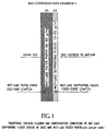
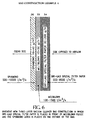
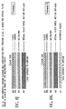
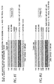
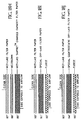
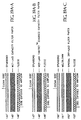
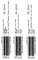
- FIG. 1 through FIG. 3 represent existing commercial vacuum cleaner bag constructions.
- FIG. 1 depicts a traditional structure consisting of wet-laid tissue fleece 24 on the inside (upstream side) of the bag and filter paper 25 on the outside (downstream side) of the bag.
- the tissue fleece serves as a pre-filter, removing only the largest dust particles.
- the filter paper typically filters out and holds in its porous structure particles greater than 10-20 ⁇ m.
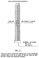
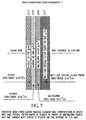
- FIG. 2 depicts a two-layer vacuum cleaner bag construction in which a meltblown (MB) fleece 26 serves as both a pre-filter, coarse filter, and fine filter by removing particles below 5 ⁇ m in diameter.
- MB fleeces have much smaller pores than typical vacuum cleaner filter paper and can not hold dust as effectively.
- the MB fleece is often electrostatically charged to enhance filtration efficiency. When the MB fibers become covered with dust, the electrostatic field may be largely diminished.
- the prior art utilizing this design is European Patent Application number 89312886.8, Publication numbers 0 375 234 B1 and 0 375 234 A1.
- the spunbond (SB) layer 27 primarily provides support for the MB fleece, and improves the abrasion resistance of the outside of the bag.
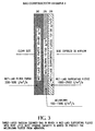
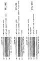
- FIG. 3 depicts a three-layer vacuum cleaner bag construction in which the wet-laid supporting fleece 28 is added to serve as a pre-filter for only very large particles of dust and to protect the MB fleece from abrasion.
- the MB fleece 29 serves to filter small and large particles and thus has a tendency to clog up very quickly, and thereby increases in pressure drop more quickly than traditional filter paper.
- the outside layer of filter paper 30 is in effect redundant for filtration and serves primarily to support the top surface of MB fleece, to strengthen the bag and to improve abrasion resistance of the outside surface of the bag. Examples of prior art depicting similar designs include European Patent Application Number 89106843.9 (Gessner) and U.S. Patent Number 5,080,702 (Home Care Industries), discussed above, In the latter no tissue fleece interlining was used.
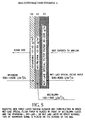
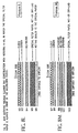
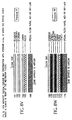
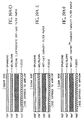
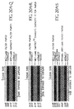
- FIG. 4 depicts the new tree-layer vacuum filter structure in which a wet-laid capacity paper, dry-laid capacity paper, or other suitable type of nonwoven coarse filter 10 is placed upstream of a filtration grade MB fleece 11.
- This upstream layer serves to remove larger dust particles and to hold the dust in its structure.
- This layer should preferably have a much less dense, bulkier structure that is capable of holding a large quantity of dust without increasing the pressure drop.
- a high bulk MB nonwoven is shown in the figure as web 10. It is preferable that the inner MB web be loftier and more open than web 11 so that it can also contain more dust without pressure drop increase.
- FIG. 5 depicts the new vacuum cleaner bag construction with a 3-layer construction, in which a wet-laid capacity paper 31 is placed in front of the filtration grade MB fleece 32 and a spunbond (SB) nonwoven 33 is placed on the outside of the bag structure.
- the inner layer 31 may be a wet-laid, dry-laid, Spunblown (Modular), microdenier spunbond or other type of nonwoven filter that has the proper porosity and dust holding capacity. It is preferable that it has higher porosity and dust holding capacity than the standard filter paper that is used in the prior art vacuum cleaner bags.
- the outer coarse filter layer may be a spunbond, wet-laid, dry-laid, or hydroentangled nonwoven, netting or other type of scrim or nonwoven.
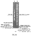
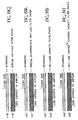
- FIG. 6 shows a vacuum cleaner bag with the same construction as shown in FIG. 5, except a dry-laid capacity paper 34 is placed in front of the MB fleece 35, and the spunbond layer 36 is again placed on the outside of the bag.
- the wet-or dry-laid filter papers were placed on the inside of the bag structure to help support the MB fleece and to filter and hold the medium and larger size dust particles so that the MB fleece could effectively filter the smaller particles without clogging up.
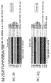
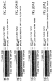
- FIG. 7 depicts the new vacuum cleaner bag construction in which a fleece/carbon combination 214+215 of respectively 50 g/m 2 , and 150 g/m 2 functioning as an odor adsorption layer is substituted for the SB 33 of FIG. 5.
- the fleece 214 downstream of the activated carbon fibers prevents those activated carbon fibers from getting into the bag compartment of the vacuum cleaner and therefore this fleece should preferably be electrostatically charged.
- FIGS. 8A-8AA depict numerous contemplated embodiments of the novel vacuum cleaner bag construction.
- a SB layer 37 forms the outside layer of the bag and serves to reinforce the bag and to protect the inner filtration grade MB fleece 38.
- the electrostatically charged MB fleece layer efficiently removes particles less than 0.1 ⁇ m in diameter.
- the vacuum cleaner bag filter paper 39 supports the MB fleece and filters and holds medium and large sized dust particles within its structure. This paper also provides the necessary rigidity for the construction to be readily fabricated into vacuum cleaner bags on standard vacuum cleaner bag making equipment.
- the layers in FIG. 8A are not bonded together.
- FIG. 8B The structure of FIG. 8B is the same as in FIG. 8A except a supporting wet-laid tissue fleece 43 is placed upstream of the paper 42.
- the supporting tissue fleece only filters out very large dust particles.
- FIG. 8C The structure of FIG. 8C is the same as 8A except that a netting scrim 47 is thermally or adhesively (with e.g., glue) sealed upstream of and to the coarse filter paper 46. That is, the scrim and coarse filter paper are bonded, preferably permanently bonded. At least any two adjacent layers of the bag can be bonded. By “permanently bonded” is meant that the bond is intended to be effective during the full normal life of the bag. Bonding can be accomplished by any suitable method such as chemical adhesive, thermal bonding and ultrasonic bonding.
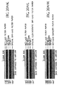
- the SB outer layer 48, filtration grade MB fleece layer 49 and SB supporting layer 50 are bonded together.
- the filter paper layer 51 is placed upstream of the SB/MB/SB laminate, and also increases the rigidity of the bag construction so that it can be readily fabricated into a vacuum cleaner bag on standard bag forming equipment
- FIG. 8E SB layer 53, MB layer 55, and filter paper layer 57 are bonded together by a porous hot melt adhesive 54 and 56.
- FIG. 8F is the same as FIG. 8E, except that a supporting wet-laid tissue fleece 64 is bonded to the construction by a hot melt adhesive 63.
- FIG. 8G is the same as FIG. 8D, except the filter paper 69 is bonded by a hot melt adhesive 68 to the bonded SB 65, MB 66 and SB 67 laminate.
- FIG. 8H is the same as FIG. 8G, except that the wet-laid tissue fleece 76 has been bonded to the construction by hot melt adhesive 75.
- FIG. 8I is the same as FIG. 8E, except that netting 82 is sealed to the construction without the use of a hot melt adhesive.
- FIGs. 8J through 8AA All contain a fleece/carbon composite layer, functioning as an odor absorption layer.
- the composite comprises an activated carbon fiber layer upstream of a backing layer of fleece.
- a fleece/carbon combination 83 + 84 forms the outside, most downstream layer of the bag, filtration grade MB fleece 85 efficiently filters particles less than 0.1 ⁇ m in diameter and coarse filter paper 86 filters and holds medium to large sized dust particles within its structure.
- FIG. 8K is the same as FIG. 8J except a supporting wet-laid fleece 91 is placed upstream of the coarse filter paper 90.
- the supporting fleece only filters out very large dust particles.
- FIG. 8L is the same as FIG. 8K, except that a netting scrim 96 is sealed to the coarse filter paper 95.
- FIG. 8M the SB layer 99, MB layer 100 and SB layer 101 are bonded together which increases the rigidity of the bag construction.
- fleece/carbon 103+104 are bonded to filtration grade MB fleece 106 by a porous hotmelt adhesive 105.
- Coarse filter paper 108 is bonded in the same way to MB 106 by hotmelt adhesive 107.
- FIG. 8N fleece/carbon 103+104 are bonded to filtration grade MB fleece 106 by a porous hotmelt adhesive 105.
- Coarse filter paper 108 is bonded in the same way to MB 106 by hotmelt adhesive 107.
- FIG. 8O shows a similar construction in which the supporting fleece 116 is bonded to filter paper 114 by a porous hotmelt at 115.
- FIG. 8P is another construction with hotmelt adhesion at 119 and 123.
- the SB 120 and 122 layers are bonded on opposite sides of filtration grade MB fleece 121 to increase the rigidity of the construction.
- FIG. 8Q is the same as FIG. 8P, but with a porous hotmelt at 133 and a supporting fleece 134 added upstream of the coarse filter paper 132.
- FIG. 8R The structure of FIG. 8R includes a netting scrim 143 sealed to the upstream side of coarse filter paper 142.
- the carbon/fleece 146 + 147 has been moved downstream of the coarse filter paper 148, and upstream of filtration grade MB fleece 145.
- the MB 145 and SB 144 layers are moved to the outer side, as seen in many of the illustrated embodiments.
- FIG. 8T is the same as FIG. 8S, with a supporting fleece 154 placed upstream of the coarse filter paper 153.
- FIG. 8U the supporting fleece of FIG. 8T has been replaced by a netting scrim 160 sealed to the coarse filter paper 159.
- the structure of FIG. 8V has an outer layer of SB 161, filtration grade MB fleece 162 and SB 163 are sealed together and the carbon/fleece 164 + 165 between those sealed layers and the coarse filter paper 166.
- Layers 161, 162 and 163 preferably are thermally point-bonded with a total bonded area of 5-50%, more preferably 10-20%. Alternatively, these layers can be bonded utilizing an adhesive.
- Layers 164 and 165 preferably are adhesively bonded together.
- the three layer 161/162/163 composite and two layer 164/165 composite preferably are not bonded to each other.
- FIG. 8W SB 169 and filtration grade MB fleece 171 are bonded together by a porous hotmelt 170, and the carbon/fleece is bonded to the coarse filter paper and MB by hotmelt adhesive layers 172 and 175.
- FIG. 8X is the same structure as FIG. 8W, except an extra supporting fleece 186 is bonded to the coarse filter paper 184 with a porous hotmelt adhesive 185.
- FIG. 8Y shows an outer composite layer of SB 187, MB 188 and SB 189 sealed together. Carbon/fleece 191/192 is bonded to this sealed outer layer and coarse filter paper by porous hotmelt adhesives 190 and 193.
- FIG. 8Z shows the same structure as FIG. 8Y but with a supporting fleece 204 bonded to the coarse filter paper 202 by a porous hotmelt adhesive 203.
- FIG. 8AA illustrates SB 205 and filtration grade MB fleece 207 bonded together with a porous hotmelt adhesive 206.
- the carbon/fleece 209 + 210 bonded in the same way to MB 207.
- Coarse filter paper 212 is adhered by hotmelt 211, and a netting scrim 213 is sealed to coarse filter paper 212.
- the activated carbon fibers layer can have the following configurations: Carbon granules between layers of nonwovens (fleece), paper with activated carbon fibers, paper with activated carbon coal, activated carbon fabrics (nonwovens), activated carbon fabrics (woven cloth), activated meltblown made of pitch and activated carbon fibers blown into a MB layer.
- the activated carbon layer preferably has a surface area of about 500-3000 g/m 2 (BET N 2 method) a weight in the range of about 25-500 g/m 2 and an air permeability of about 500-3000 L/(m 2 x s), DIN 53887.
- the enhanced performance bag comprises a multipurpose filtration layer positioned upstream of a second filtration layer.
- the multipurpose filtration layer can be either a dry-laid high dust capacity paper or a wet-laid high dust capacity paper, high bulk meltblown, Spunblown (Modular) or microdenier spunbond.
- the second filtration layer should be a wet laid filter paper, dry-laid filter paper or a spunbond which may be electrostatically charged, preferably before constructing the bag.
- multipurpose filtration layer is used to denote that the pre-filter layer of dry-laid or wet-laid capacity paper is capable of performing several functions simultaneously.
- This layer protects the downstream second filtration layer from shock loading by blocking large bursts of dirt particles which can be of size much greater than 10 ⁇ m.
- the multipurpose layer filters smaller particles of about 10mm size. Its porosity and thickness are sufficiently great that this layer has capacity to hold within the layer a large quantity of dirt and dust particles while allowing air flow to permeate the layer at high rate without dramatically increasing pressure drop through the composite structure. Hence, the bag can continue to operate at optimum air flow for vacuum cleaning for times long enough for the bag to reach particle holding capacity.
- the multipurpose filtration layer cleans the air of most particles other than fine dust particles which are removed by the second filtration layer.
- second filtration layer denotes a filter layer which is intended to remove from the air passed by the multipurpose layer a sufficient amount of fine dust particles to produce a very high overall filtering efficiency, preferably over 99%.
- the second filtration layer is less porous than the multipurpose layer. It can have moderate porosity because the multipurpose filtration layer performs the overwhelming majority of the filtration load thereby leaving only the small amount of fine dust size particles to be removed by the high efficiency filter layer. This is particularly the case when the multipurpose filtration layer includes electrostatically charged split film fibers or when an electrostatically charged high bulk meltblown, Spunblown Modular or microdenier spunbond is utilized. In these cases, the upstream layers are effective to remove at least a portion of the fine dust size particles as well as larger particles. This leaves even less fine dust to be removed by the second filtration layer.
- the various layers of the enhanced performance bag usually are adhered to adjacent layers at the bag inlets and outlets, and sometimes at the bag seams. They can be unadhered over other portions of the bag structure to adjacent layers or adhered by diverse methods.
- the layers can be adhered by adhesives, thermal bonding, ultrasonic bonding or a combination of these.
- basis weight was determined by I.S.O. 536, thickness by DIN 53 105 (0.2 bar), air permeability by DIN 53 887, tensile strength machine direction (MD) and cross machine direction (CD) by DIN 53 112, Mullen's burst pressure (MBP) by DIN 53 141, and filtration properties by T.S.I. 8160 filter tester.
- air flow direction is shown by arrows.
- test was employed to characterize the performance of vacuum bag filter composites with respect to filtering fine dust particles.
- the test basically involves filtering a 500 mg sample of SAE fine test dust through a circular 200 square centimeter of filter medium being tested using an air flow of 10 liters per second within a 30 second time period. The pressure drop through the test filter medium is measured before and after filtration.
- An absolute filter is employed to capture particles which pass the test filter.
- a coefficient of retention expressed as a percentage is calculated from the quotient of the weight of sample captured by the test filter divided by the total of the test filter-captured sample weight and the weight of sample caught by the absolute filter.
- a TSI Model 8110 filter tester was used for the measurement of media filtration efficiency.
- 2.0 % sodium chloride solution (20g NaCl in 1 liter of water) was aerosolized by an aerosol generator.
- the NaCl water drops in aerosol were heated and NaCl crystallites with a 0.1 ⁇ m diameter were formed.
- the mass concentration of NaCl in the air was 101 mg/m 3 .
- Photometry was used to detect the volume concentration of the air in the upstream volume of the media (Cu) and the volume concentration of the air in the downstream volume of the media (Cd).
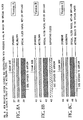
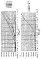
- FIGs. 1-3 and 4-7 Samples of various vacuum cleaner bag constructions shown in FIGs. 1-3 and 4-7 were prepared and tested. Examples 1, 2, and 3 are typical prior art construction and Examples 4, 5, 6, and 7 are representative of bags according to this invention. Characteristics of the layers of the prior art and novel bag constructions were determined and are presented in Tables III and IV. Weight, thickness, air permeability, pore diameter and filtration level permeability of the overall composites are shown in Table V. Table V also presents pressure drop and air flow through the composite at fine dust loading measured in increments from 0 to 2.5 grams by DIN 44956-2. Pressure drop data of Table V are plotted in FIGs. 9 and 10. Air flow data are graphed in FIG. 11.
- FIG. 9 shows that the three conventional constructions, Examples 1, 2 and 3 started to notably increase in pressure drop after only 1.0 gram of dust loading.
- Examples 5, 6 and 7 of this invention showed very little pressure increase, even after the maximum loading of 2.5 grams of dust. Furthermore, the initial filtration efficiencies of Examples 5-7 were all at least as high as the prior art samples containing MB fabrics at 99.6%. Example 1, which contained no MB had a lower filtration efficiency of 96%, and it had the highest pressure drop with dust loading.
- a distinguishing difference between Examples 2 and 3 and Examples 5-7 is that the coarse filter paper was upstream of the MB fleece in the latter three Examples. This enabled the filter paper to filter and hold the dust particles, particularly the larger dust particles, so that the filtration grade MB fleece can filter out the smaller sized dust particles without clogging up the pores, even at a loading of 2.5 g/m 2 .
- both the MB and the filter paper used in Examples 4, 5, 6 and 7 are notably more open than the corresponding materials used in Examples 1, 2 and 3.
- the special coarse filter paper is much more open, as evidenced by the high air permeability rates.
- the special filter paper is able to hold more dust.
- the air permeability of the MB in Examples 4, 5, 6 and 7 is much higher, and the high bulk MB nonwoven is much loftier and less dense. This is accomplished by a number of ways in the manufacture of MB, but more often this is done by increasing the die-to-collector distance to allow for greater quenching of the MB filaments so that the semi-molten filaments will have more time to cool and completely solidify before being deposited onto the collector. Water spray mists or chilled quench air may also be used to accelerate the cooling of the extruded MB filaments.
- Example 2 from FIG. 9 is again plotted in FIG. 10 and labeled as “3M.”
- the novel example, labeled as “Example 4, Airflo” was constructed by first making a very porous, very lofty, high bulk MB nonwoven with a weight of 120 g/m 2 , which was used as the most upstream layer. This very MB web was loftier and more porous than the conventional MB fabrics used in Examples 2 and 3. Accordingly, it served to filter out and hold a large quantity of dust particles.
- the Airflo Example 4 resulted in negligible pressure drop increase with dust loading up to the maximum dust loading of 2.5 g/m 2 .
- Example 1 did not contain any MB fleece, and had less pressure drop increase than Examples 2 and 3, it still had substantially greater pressure drop increase wit loading than did Examples 5 and 6, had MB fleeces.
- the weight of MB polypropylene web used in three of the examples was 22 g/m 2 .
- the proper placement of the coarse filter paper and filtration grade MB fleeces in Examples 5 and 6 resulted in dramatically lower pressure drop increase, because this enabled the filter paper to remove and hold the large and medium sized particles, and the filtration grade MB fleece only had to filter and contain the finer particles.
- the pressure drop was slightly greater with the wet-laid paper because hydrogen bonding between the cellulose molecular chains during wet processing makes the wet-laid paper denser with somewhat smaller pores at the same weight.
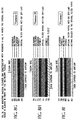
- FIG. 11 shows the results of examples which further dramatize the appreciable improvements obtained by placing a coarse filter paper upstream of the filtration grade MB fleece (on the inside of the bag) of this invention.
- Separate bags of Examples 1-3 and 5-7 were loaded with fine dust in 0.5 gram increments of 0, 0.5, 1.0, 1.5, 2.0 and 2.5 grams of dust. Then the six bags with different degrees of dust loading were subjected to an air permeability test in which the maximum sustainable amount of air was passed through each bag sample.
- the novel bag construction, represented by Example 6 had a maximum sustainable airflow with no dust loading of 445 L/(m 2 x s)compared to only 225 L/(m 2 x s)with the prior art Example 3.
- Example 6 had a sustained airflow of 265.4 L/(m 2 x s)compared to only 34.9 L/(m 2 x s)with conventional Example 3, and at 2.5 grams of loading the performance differences were even more remarkable - 199.8 and 21.9 L/(m 2 x s).
- Example 2 had a maximum sustainable airflow of 411 L/(m 2 x s), but already at 1.0 gram of dust loading values drop to those of conventional bag constructions.
- a conventional vacuum cleaner bag suffers from a relatively low airflow as seen by 18, 14.9 and 21. 9 L/(m 2 x s) of Examples 1, 2 and 3 in FIG. 11 after the 6 th dust loading. It is almost impossible to add another layer of material to these constructions without reducing the airflow dramatically. In Examples 5 and 6 of FIG. 11, due to the excellent performance of the new constructions, a possibility has been created to add more functions to the vacuum cleaner bag. In today's vacuum cleaners a number of different filters are used, amongst them active carbon filters to absorb odors. Very often 3-5 different filters are used in a vacuum cleaner, each one having its own service life.
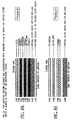
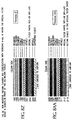
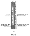
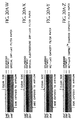
- Fig. 12 shows a cross section of a commercially available vacuum cleaner bag structure 51 ' consisting of a wet-laid tissue fleece liner 52 ' on the inside (upstream air side) of the bag and a standard wet-laid filter paper 53 ' on the outside (downstream air side) of the bag.
- the liner primarily protects the wet-laid filter paper from abrasion, but also pre-filters out some of the largest particles.
- the wet-laid filter paper typically filters out particles greater than about 10 ⁇ m and some smaller particles.
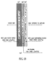
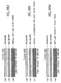
- Fig. 13 shows a cross section of a conventional three-layer vacuum cleaner bag structure 54 ' in which a wet-laid tissue supporting fleece 55 ' with very little dust holding capacity is added upstream of a MB fleece 56 ' to protect from abrasion and a wet-laid filter paper 57 ' is placed on the outside (downstream) to protect the bag from abrasion, to improve stiffness for bag fabrication and to provide additional air filtration.
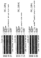
- Properties of the individual layers and composite structure are presented in Table VI.
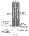
- Fig. 14 depicts a novel three-layer vacuum cleaner bag composite structure 58 ' of Example 8 with a wet-laid high dust capacity paper layer 59 ' on the inside (upstream air side) in front of a melt blown filter layer 60 '.
- a highly air permeable wet-laid filter paper layer 61 ' is on the outside (downstream air side).
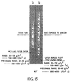
- Fig. 15 depicts a novel inventive vacuum cleaner bag composite structure 62 of Example 9 in which a dry-laid high dust capacity paper 63 ' consisting of 100% fluff pulp fibers held together by 20 weight % latex binder is positioned as the inside layer and a conventional wet-laid filter paper 64 ' is the outside layer.
- a dry-laid high dust capacity paper 63 ' consisting of 100% fluff pulp fibers held together by 20 weight % latex binder is positioned as the inside layer and a conventional wet-laid filter paper 64 ' is the outside layer.
- Fig. 16 depicts a novel vacuum cleaner bag construction 65 ' of Example 10 consisting of a thermally bonded, dry-laid high dust capacity paper 66 ' in the upstream air position inside the bag with a highly permeable wet-laid filter paper 67 ' on the outside of the bag.
- the fiber content of the dry-laid high dust capacity paper 66 ' consists of a blend of 40% fluff pulp fibers, 40% split film fibers and 20% bicomponent polymer fibers.
- Properties of the individual layers and composite structures are presented in Table VI which compares filtration properties of various composite structures at 100 L/min. flow. Data in Table VI shows that Examples 8 and 10 structures produced dramatically increased filtration efficiency relative to Comp. Ex. 1 with only slight pressure drop increase. Also, Example 8 produced slightly better filtration efficiency at the same pressure drop as Comp. Ex. 2.
- Example 9 compared well with commercially available Comp. Ex. 1 structure.
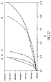
- Fig. 17 is a plot of the pressure drop across the bag structures versus grams of fine dust loading in which curves A-E represent Comparative Examples 1 and 2, (A and B) and Examples 8-10 (C, D and E), respectively.
- the plot shows that conventional bag structures attained high pressure drops rapidly with very low loadings (i.e., about 100 mbar at less than 2.5g).
- Example 8 arrived at equivalent high pressure drop after 3.5 g dust loading, which is approximately 40% improvement.
- Examples 9 and 10 produced remarkably superior fine dust loading results by reaching about 100 mbar pressure drop at about 10 g and 12.5 g.
- Examples 9 and 10 do not include MB filter interlayer between the upstream high dust capacity mutipurpose layer and the downstream second filtration layer.
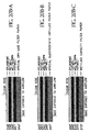
- Fig. 18A shows a two-layer structure in which the upstream, multipurpose layer is a dry-laid filter composition of exclusively fluff pulp fibers held together with a dried latex binder, or of a blend of bicomponent polymer fibers and fluff pulp fibers which are thermally bonded.
- the multipurpose layer has high air permeability and dust holding capacity.
- Fig. 18B also shows a two-layer structure in which the multipurpose layer is a three component blend of fluff pulp fibers, bicomponent polymer fibers and electrostatically charged split film fibers. Again, the blend is held together by thermal bonding, primarily of the low-melting bicomponent polymer fiber composition.
- Fig. 18C shows another two-layer structure with specially developed, high dust holding capacity wet-laid filter paper in the upstream position.
- the fibers in the wet laid paper are a blend of synthetic fibers and natural, i.e., wood pulp, fibers.
- the synthetic fibers are polyester, and more preferably, polyethylene terephthalate.
- the fibers are bonded by a latex binder at about 10-30 wt% dry binder solids based on fiber weight.
- Fig. 18D illustrates a two-layer structure in which the upstream, multipurpose layer comprises polyolefin, and preferably polypropylene fibers. This layer is electrostatically charged.
- the Tantret(TM) technology Preferably, the Tantret(TM) technology.
- Figs. 18E-18H show structures which are the same as those of Figs 18A-18D, respectively, except that an optional, meltblown fleece interlayer is inserted between the multipurpose filter layer and the second filtration layer.
- Figs. 18I-18P show structures which correspond to Figs. 18A-18H, respectively, except that an optional fleece scrim has been added to the side of the vacuum fitter bag exposed to the airflow to protect the next layer from abrasion and to filter some of the very large dust particles.
- Figs. 19Q-19AF show structures which correspond to Figs. 18A-18P, respectively, except that an optional spunbond fleece is placed in the most downstream layer position and hence is on the outside of the vacuum cleaner bag.
- Figs. 20AG-20BL show structures which correspond to Figs. 18A-19AF, respectively, except that adjacent layers of the composite are bonded by a hot melt adhesive.
- the hot melt may also be replaced or used in conjunction with all known methods of laminating, including glues and thermal and ultrasonic bonding.
Abstract
Description
- This invention relates to a novel disposable vacuum cleaner bag composition which is notably superior to existing vacuum cleaner bag constructions in terms of dust holding capacity, minimal increase in pressure drop with dust loading, and in ease of bag fabrication and shape retention, while achieving filtration efficiency values which compare most favorably with premium commercially available bags.
- This disclosure describes two principal embodiments of a novel vacuum cleaner bag filter which are linked to form a single general inventive concept in that the embodiments relate to a multilayer vacuum cleaner bag.
- Over the last few years, a number of companies have developed raw materials and components for vacuum cleaner bags to replace the older single layer paper bag and the well-known two-ply bag, having a downstream filter paper and an upstream tissue paper, with bags having upstream layers of either wet-laid tissues or fibrous fleeces such as meltblown (MB) ultra-fine webs occasionally referred to herein as "filtration grade MB fleece." Some manufacturers of vacuum cleaners have even marketed bagless vacuum cleaners to avoid the cost of bags. However, this type of vacuum cleaner has less suction and the compartment holding the dust must be emptied manually, and this largely nullifies its advantages by exposing the worker and the environment to the concentrated dust. Nevertheless, the bagless cleaner has prompted manufacturers to continue to improve the overall performance of bags. Additionally it relates to fibrous components randomly laid in three dimensions by dry-laying and wet-laying technologies to provide low density and high bulk for novel filters with greater air permeability and particulate holding capacity.
- The prior art addressed the problem of providing a vacuum cleaner bag with improved filtration efficiency. U.S. Patent No. 5,080,702, Home Care Industries, Inc. discloses a disposable filter container-like bag which comprises an assembly of juxtaposed plies, namely an inner and outer ply of air pervious material. U.S. Patent No. 5,647,881 (EPO 0 822.775 B1) discloses a three layer composite of an outer support layer, middle charged fibrous filter layer having specific properties and an inner diffusion layer unbonded except at least at one seam to the fibrous filter layer. The diffusion layer is described to provide the filter bag as its main function, with resistance to shock loading. EPO 0 338 479 to Gessner discloses a dust filter bag with a fibrillated fleece-lined outer layer of filter paper. The filtration grade fibrillated fleece layer is upstream of the filter paper.
- In the vacuum bag of the invention the principal function of the inner layer is that of high dust-holding capacity, a property of this magnitude not yet disclosed in the prior art.
- The disclosures of the above-mentioned patents are incorporated herein in their entirety by reference.
- With the advent of electrostatically charged MB fleeces, it has been possible to produce bag laminates with filtration efficiencies on the order of 99.8-99.9% to fine dust at a moderate airflow. However, conventional MB webs are essentially flat filters. Consequently, filter structures that utilize MB webs quickly load up with dust, reduce the air suction, and lose further dust pick up ability by the vacuum cleaner. Today, the standard dust bags have an air permeability of 200 to 400 L/(m2x s). It is desirable to have a combination of paper types and other liners, including MB liners that would yield a high efficiency of up to 99.9% and also, allow a high flow with minimal pressures gradient increase measured by the DIN 44956-2 Test.
- A primary object of this invention is to provide a novel vacuum cleaner bag composition capable of extremely high filtration efficiency to fine dust and of maximum performance of a vacuum cleaner in terms of continuous high suction for picking up dust without a notable increase in pressure drop until the bag is filled.
- A second objective of this invention is to provide a bag with a composition such that it has the rigidity needed for it to be fabricated and shaped on conventional vacuum cleaner bag making equipment.
- A third objective of this invention is to construct a vacuum cleaner bag media that by virtue of its excellent filtration efficiency and superior non-blocking, high airflow performance, will be most suitable to the new European trend of small vacuum cleaners, with of course, smaller vacuum dust bags.
- These and other objectives of this inventor will become apparent to one skilled in the art from the following disclosure.
- The Nonwoven Fabrics Handbook of the Association of the Nonwoven Fabrics Industry, 1992, is incorporated herein in its entirety by reference.
- A disposable vacuum cleaner bag that has an air permeability of greater than 400 L/(m2x s) was developed, This was accomplished by placing a filter paper on the upstream air side of a filtration grade MB fleece/spunbond two-ply component, instead of placing a filter paper on the outside (i.e., downstream air side) of the bag, as is typically done. It should be noted, however, that prior art bag constructions often place a lightweight (typically 13 g/m2) tissue fleece upstream of the MB fleece for support and to protect the MB fleece from abrasion. This lightweight tissue fleece only filters some of the largest dust particles.
- In the new filter bag construction, it is possible to use a coarse filter paper ocassionally referred to herein as "high dust holding capacity," "multipurpose" or "capacity" paper or layer, on the most upstream layer inside the bag. This invention also allows for optional use of lightweight tissue fleece, netting or other scrim on the most inside layer upstream of the filter paper. Thus, large dust particles are removed by the coarse filter paper (and possibly to a minor extent by the light weight tissue fleece, if used). The filtration grade MB part of the bag fabric can serve more effectively as a filter without clogging up, since it does not need to hold the bulk of the dust. If desired, a wet-laid tissue may also be used in front of the coarse paper. This construction is very much unlike the earlier constructions that used MB liners on the inside of the bag, and which depended upon the MB web for both dust holding and filtration. Furthermore, the paper gives the bag the rigidity needed to fabricate and shape the novel bag composition on conventional vacuum cleaner bag making equipment.
- The novel vacuum cleaner bag thus comprises a flat composite of a coarse filter layer comprising at least one of (a) a wet-laid high dust holding capacity paper, (b) a dry-laid high dust holding capacity paper, (c) a high bulk meltblown nonwoven, (d) a Spunblown (Modular) nonwoven, and (e) a microdenier spunbond nonwoven positioned upstream in the direction of air flow of a filtration grade meltblown fleece layer formed into the bag having at least one air inlet defining means in the flat composite and at least one seam forming the flat composite into the bag. The filter layer operative according to this invention which is positioned downstream of the course, capacity layer is sometimes referred to herein as a "secondary" or "high efficiency filtration" layer.
- There is also now provided according to another embodiment of this invention a composite structure for an enhanced performance vacuum cleaner bag comprising a multipurpose filtration layer occasionally referred to herein as "high dust holding capacity", "coarse", or "capacity" paper or layer positioned upstream in the direction of air flow of a second filtration layer selected from among (a) a wet-laid filter paper having a basis weight of about 30-100 g/m2 and air permeability of about 100-3000 L/(m2 x s), and (b) a thermally bonded spunbond nonwoven having basis weight of about 10-100 g/m2 and air permeability of about 500-10,000 L/(m2 x s), and preferably about 2,000-6,000 L/(m2 x s).
- A preferred example is a thermally bonded dry-laid high dust capacity paper containing a blend of fluff pulp, bicomponent fibers (for thermal bonding) and electrostatically charged split film fibers. Basically, in one aspect, the novel enhanced performance vacuum cleaner bag composite structure embodies placing a wet-or dry-laid capacity paper of air permeability up to about 8,000 L/(m2 x s) in front of a wet-laid filter paper of air permeability up to about 3000 L/(m2 x s).
- In another aspect, this invention provides for optional inclusion of a meltblown fleece interlayer having a basis weight of about 10-50 g/m2 and an air permeability of about 100-1500 L/(m2 x s) positioned between the multipurpose filtration layer and the second filtration layer. In a variation, the optional meltblown fleece interlayer can be electrostatically charged.
- A scrim of typically about 13 g/m2 basis weight may be placed on one or both sides of the multipurpose filtration layer/second filtration layer pair for improved abrasion resistance and ease of bag fabrication. Preferably, the scrim is positioned as the most upstream layer of the structure. Also, any or all of the layers in the novel enhanced performance bag constructions may be adhered by hot melt adhesives, glues or by thermal or ultrasonic bonding, or by a combination of these laminating methods.
- A vacuum cleaner bag utilizing the enhanced performance composite structure of this invention has been found to have filtration efficiency performance favorably comparable to other vacuum cleaner bag structures. The enhanced performance structures generally have better than a 95% efficiency to the DIN 44956-2 test and can typically undergo two to three times as many DIN dust loading cycles as comparable bag constructions. They also have up to five times the DIN loading cycles as conventional bag constructions characterized either by a scrim in front of standard wet-laid paper or by a MB filter fleece in front of a standard wet-laid paper. With the optional electrostatically charged MB interlayer the new constructions have superior high fine dust filtration efficiency to 0.1-0.3 µm NaCl particles.
- High filtration grade fleeces such as electrostatically charged MB, spunbond modular and microdenier spunbond media may also be incorporated into the new constructions of this invention.
-
- FIG. 1 is a schematic cross-section of a traditional vacuum cleaner bag construction consisting of wet-laid tissue (inside of bag) and filter paper (air outlet side).
- FIG. 2 is a schematic cross-section of a two-layer vacuum cleaner bag in which MB ultra-fine fiber fleece inside of bag serves as both the dust holding and filtering components.
- FIG. 3 is a schematic cross-section of a three-layer vacuum cleaner bag in which a wet-laid tissue fleece with very little dust holding capacity is added to protect the MB fleece from abrasion.
- FIG. 4 is a schematic cross-section of a three-layer vacuum cleaner bag construction according to this invention in which a special bulky MB is placed in front of a filtration grade MB fleece and the spunbond layer is placed on the outside of the bag.
- FIG. 5 is a schematic cross-section of a three-layer vacuum cleaner bag construction according to this invention in which wet-laid capacity paper is placed in front of filtration grade MB fleece. The outer layer may be a spunbond, wet-laid, dry-laid, hydroentangled nonwoven, netting or any other type of nonwoven or woven scrim.
- FIG. 6 is a schematic cross-section of a three-layer vacuum cleaner bag construction according to this invention in which dry-laid capacity paper is placed in front of meltblown fleece. The outer layer may be a spunbond, wet-laid, dry-laid, hydroentangled or other type of nonwoven scrim.
- FIG. 7 is a schematic cross-section of an innovative vacuum cleaner bag of Example 7 in which a fleece/carbon layer has been placed as an odor absorption layer with basically the same filtration properties as a filter combination only filtering dust.
- FIG. 8A is a schematic cross-section of an embodiment of the vacuum cleaner bag construction according to this invention.
- FIG. 8B is another schematic cross-section of an embodiment of the vacuum cleaner bag construction according to this invention.
- FIG. 8C is another schematic cross-section of an embodiment of the vacuum cleaner bag construction according to this invention.
- FIG. 8D is another schematic cross-section of an embodiment of the vacuum cleaner bag construction according to this invention.
- FIG. 8E is another schematic cross-section of an embodiment of the vacuum cleaner bag construction according to this invention.
- FIG. 8F is another schematic cross-section of an embodiment of the vacuum cleaner bag construction according to this invention.
- FIG. 8G is another schematic cross-section of an embodiment of the vacuum cleaner bag construction according to this invention.
- FIG. 8H is another schematic cross-section of an embodiment of the vacuum cleaner bag construction according to this invention.
- FIG. 8I is another schematic cross-section of an embodiment of the vacuum cleaner bag construction according to this invention.
- FIG. 8J is another schematic cross-section of an embodiment of the vacuum cleaner bag construction according to this invention.
- FIG. 8K is another schematic cross-section of an embodiment of the vacuum cleaner bag construction according to this invention.
- FIG. 8L is another schematic cross-section of an embodiment of the vacuum cleaner bag construction according to this invention.
- FIG. 8M is another schematic cross-section of an embodiment of the vacuum cleaner bag construction according to this invention.
- FIG. 8N is another schematic cross-section of an embodiment of the vacuum cleaner bag construction according to this invention.
- FIG. 8O is another schematic cross-section of an embodiment of the vacuum cleaner bag construction according to this invention.
- FIG. 8P is another schematic cross-section of an embodiment of the vacuum cleaner bag construction according to this invention.
- FIG. 8Q is another schematic cross-section of an embodiment of the vacuum cleaner bag construction according to this invention.
- FIG. 8R is another schematic cross-section of an embodiment of the vacuum cleaner bag construction according to this invention.
- FIG. 8S is another schematic cross-section of an embodiment of the vacuum cleaner bag construction according to this invention.
- FIG. 8T is another schematic cross-section of an embodiment of the vacuum cleaner bag construction according to this invention.
- FIG. 8U is another schematic cross-section of an embodiment of the vacuum cleaner bag construction according to this invention.
- FIG. 8V is another schematic cross-section of an embodiment of the vacuum cleaner bag construction according to this invention.
- FIG. 8W is another schematic cross-section of an embodiment of the vacuum cleaner bag construction according to this invention.
- FIG. 8X is another schematic cross-section of an embodiment of the vacuum cleaner bag construction according to this invention.
- FIG. 8Y is another schematic cross-section of an embodiment of the vacuum cleaner bag construction according to this invention.
- FIG. 8Z is another schematic cross-section of an embodiment of the vacuum cleaner bag construction according to this invention.
- FIG. 8AA is another schematic cross-section of an embodiment of the vacuum cleaner bag construction according to this invention.
- FIG. 9 is a plot of pressure drop (mbar) across vacuum cleaner bags versus Fine Dust Loading (PTI/fine) per DIN 44956-2 as performed on Examples 1-3 and 5-7.
- FIG. 10 is a plot of pressure drop (mbar) across vacuum cleaner bags versus Fine Dust Loading per DIN 44956-2 as performed on Example 4, Airflow and Example 2, 3M.
- FIG. 11 is a graph showing a comparison of airflow versus Fine Dust Loading (PTI/fine).
- FIG. 12 is a schematic cross section of a traditional vacuum cleaner bag construction.
- FIG. 13 is a schematic cross section of another vacuum cleaner bag construction.
- FIG. 14 is a schematic cross section of an embodiment of an enhanced performance bag structure having a melt blown interlayer according to this invention.
- FIG. 15 is a schematic cross section of another embodiment of an enhanced performance bag structure having a latex bonded fluff pulp fiber dry-laid high dust capacity multipurpose layer upstream of a wet-laid paper second filtration layer according to this invention.
- FIG. 16 is a schematic cross section of another embodiment of an enhanced performance bag structure having a thermally bonded, dry-laid high dust capacity multipurpose layer upstream of a wet-laid paper second filtration layer according to this invention.
- FIG. 17 is a plot of pressure drop across selected vacuum cleaner bag structures versus fine dust loading.
- FIGs. 18A-18P are schematic cross sections of selected embodiments of enhanced performance bag structures of this invention in which wet-laid paper layer is the most downstream layer.
- FIGs. 19Q-19AF are schematic cross sections of selected embodiments of enhanced performance bag structures of this invention in which a spunbond fleece layer is the most downstream layer.
- FIGs. 20AG-20BL are schematic cross sections of selected embodiments of enhanced performance bag structures of this invention in which adjacent layers are bonded by a hot melt adhesive.
-
- The filter structures of this invention apply to vacuum cleaner bags, and more generally to vacuum filters. By "vacuum filter" is meant a filter structure intended to operate by passing a gas, preferably air, which entrains usually dry solid particles, through the structure. The convention has been adopted in this application to refer to the sides and layers of the structure in relation to the direction of air flow. That is, the filter inlet side is "upstream" and the filter discharge side is "downstream" for example. Occasionally herein the terms "in front of" and "behind" have been used to denote relative positions of structure layers as being upstream and downstream respectively. Of course, there will be a pressure gradient, sometimes referred to as "pressure drop", across the filter during filtration. Vacuum cleaners typically use bag shaped filters. Normally, the upstream side of a vacuum bag filter is the inside and the downstream side is outside.
- DIN 44956-2: The DIN 44956-2 was employed to determine the increase in pressure drop of five different examples of vacuum cleaner bag constructions after dust loading with fine dust at the following levels: 0, 0.5, 1.0, 1.5, 2.0, and 2.5 grams.
- Air Permeability after Fine Dust Loading Test: The dust loading part of the DIN 44956-2 was performed at 0.5 gram increments from 0 to 2.5 g/m2/s on seven bags of each sample. However, the pressure drop values were not recorded again. The maximum sustainable air permeability values were then determined on the bags, which had the specified levels of dust loading.
- Types of papers which are referred to in this patent application are described in greater detail as follows:
- This type of paper has traditionally been used as a single ply in which it provides dust filtration and containment, as well as the strength and abrasion resistance required of a vacuum cleaner bag. This paper is also rigid enough to enable easy fabrication on standard bag manufacturing equipment. The paper is predominantly composed of unbleached wood pulp with 6-7% of a synthetic fiber such as poly[ethylene terephthalate] (PET) type polyester, and is produced by the wet laying process. The standard paper typically has a basis weight of about 30-80 g/m2 and commonly about 50 g/m2. The PET fibers typically have a fineness of 1.7 dtex and lengths of 6-10 mm. This paper has air permeability in the range of about 200-500 L/(m2 x s) and an average pore size of about 30 µm. However, the efficiency as determined from the DIN 44956-2 Test is only about 86%. Another disadvantage is that the pores are quickly clogged with dust and the dust holding capacity is further limited by the very thin paper thickness of only about 0.20 mm.
- A nonwoven of spunbond polymer fibers can be deployed as a secondary filtration layer positioned downstream of the coarse layer. The fibers can be of any spunbond-capable polymer such as polyamides, polyesters or polyolefins, Basis weight of the spunbond nonwoven should be about 10-100 g/m2 and preferably about 30-40 g/m2. The spunbond nonwoven should have an air permeability of about 500-10,000 L/(m2 x s), and preferably about 2,000-6,000 L/(m2 x s) as measured by DIN 53887. The spunbond can also be electrostatically charged.
- Scrim refers to a generally light basis weight, very open porous paper or nonwoven web. Basis weight of the scrim is typically about 10-30 g/m2, and frequently about 13-17 g/m2. The scrim, sometimes referred to as a supporting fleece usually has air permeability of about 500-10,000 L/(m2 x s). It is primarily employed to protect the high dust capacity multipurpose layer from abrasion. The scrim can also filter the very largest particles. The scrim, as well as any layer of the bag, can be electrostatically charged provided the material has suitable dielectric properties.
- Wet-laid High Dust Capacity Paper, frequently referred to herein as "wet-laid capacity paper" is bulkier, thicker and more permeable than the standard vacuum cleaner bag filter paper. In its role as a pre-filter in the vacuum cleaner bag composite it performs multiple functions. These include resisting shock loading, filtering of large dirt particles, filtering a significant portion of small dust particles, holding large amounts of particles while allowing air to flow through easily, thereby providing a low pressure drop at high particle loading which extends the life of the vacuum cleaner bag.
- The wet-laid capacity paper usually comprises a fiber mixture of wood pulp fibers and synthetic fibers. It typically contains up to about 70% wood pulp and correspondingly more synthetic fiber, such as PET, than the standard paper described above. It has a greater thickness than the standard paper of about 0.32 mm at a typical basis weight of 50 g/m2. Pore size also is much greater, in that the average pore size can be greater than 160 mm. Thus, the paper is able to hold much more dust in its pores before clogging up. Basis weight of the wet-laid capacity paper typically is about 30-150 g/m2 and preferably about 50-80 g/m2.
- The wet-laid capacity paper has a fine dust particle filtration efficiency of about 66-67 % as determined by the DIN 44956-2. Importantly, the wet-laid capacity paper has air permeability higher than the standard filter paper. The permeability lower limit thus preferably should be at least about 500 L/(m2 x s), more preferably at least about 1,000 L/(m2 x s) and most preferably at least about 2,000 L/(m2 x s). The upper limit of permeability is defined to assure that the paper filters and holds a major fraction of the dust particles larger than about 10mm. Consequently, the downstream secondary high efficiency filter medium is able to filter out and contain fine particles much longer before showing indication of a substantial pressure drop increase across the filter. Accordingly, the air permeability of the wet-laid capacity paper preferably should be at most about 8,000 L/(m2 x s), more preferably at most about 5,000 L/(m2 x s), and most preferably at most about 4,000 L/(m2 x s). It is thus seen that the wet-laid capacity paper is especially well designed as a multipurpose filtration layer to be positioned upstream of the secondary high efficiency filtration layer.
- Prior to this invention, dry-laid high dust capacity paper, sometimes referred to herein as "dry-laid capacity paper", had not been used as a filter in vacuum cleaner bags. Dry-laid paper is not formed from a water slurry, but is produced with air-laying technology and preferably by a fluff pulp process. Hydrogen-bonding which plays a large roll in attracting the molecular chains together does not operate in the absence of water. Thus, at the same basis weight, dry-laid capacity paper, is usually much thicker than standard paper and the wet-laid capacity paper. For a typical weight of 70 g/m2, the thickness is 0.90mm, for example.
- The dry-laid capacity paper webs can be bonded primarily by two methods. The first method is latex bonding in which the latex binder may be applied from water-based dispersions. Saturation techniques such as spraying or dipping and squeezing (padder roll application) followed in both cases by a drying and heat curing process can be used. The latex binder may also be applied in discrete patterns such as dots diamonds, cross hatches or wavy lines by gravure roll followed by drying and curing.
- The second method is thermal bonding, for example by utilizing binder fibers. Binder fibers sometimes referred to herein as "thermally bondable fusing fibers" are defined by the Nonwoven Fabric Handbook, (1992 edition) as "Fibers with lower softening points than other fibers in the web. Upon the application of heat and pressure, these act as an adhesive." These thermally bondable fusing fibers generally completely melt at locations where sufficient heat and pressure are applied for the web, thereby adhering the matrix fibers together at their cross-over points. Examples include co-polyester polymers which when heated adhere a wide range of fibrous materials.
- In a preferred embodiment thermal bonding can be accomplished by adding from at least 20% preferably up to 50% of a bicomponent ("B/C") polymer fiber to the dry-laid web. Examples of B/C fibers include fibers with a core of polypropylene ("PP") and a sheath of more heat sensitive polyethylene ("PE"). The term "heat sensitive" means that thermoplastic fibers soften and become sticky or heat fusible at a temperature of 3-5 degrees C below the melting point. The sheath polymer preferably should have a melting point in the range of about 90-160°C and the core polymer should have a higher melting point, preferably by at least about 5°C higher than that of the sheath polymer. For example, PE melts at 121° C and PP melts at 161-163° C. This aids in bonding the dry-laid web when it passes between the nip of a thermal calendar or into a through-air oven by achieving thermally bonded fibers with less heat and pressure to produce a less compacted, more open and breathable structure. In a more preferred embodiment the core of the core/sheath of the B/C fiber is located eccentric of the sheath. The more that the core is located towards one side of the fiber the more likely that the B/C fiber will crimp during the thermal bonding step, and thereby increase the bulk of the dry-laid capacity. This will, of course, improve its dust holding capacity. Thus, in a still further preferred embodiment the core and sheath are located side-by-side in the B/C fiber, and bonding is achieved with a through-air oven. A thermal calendar, which would compress the web more than through-air bonding and is less preferred in this case. Other polymer combinations that may be used in core/sheath or side-by-side B/C fibers include PP with co-polyester low melting polymers, and polyester with
nylon 6. The dry-laid high capacity layer can also be constituted essentially completely by bicomponent fibers. - Generally, the average pore size of dry-laid capacity is intermediate between the pore size of the standard paper and wet-laid capacity paper The filtration efficiency as determined by the DIN 44956-2 Test is approximately 80%. Dry-laid capacity paper should have about the same basis weight and the same permeability as the wet-laid capacity paper described above, i.e., in the range of about 500-8000 L/(m2 x s), preferably about 1000-5000 L/(m2 x s) and most preferably about 2000-4000 L/(m2 x s). It has excellent dust holding capacity and has the advantage of being much more uniform in weight and thickness than the wet-laid papers.
- Several preferred embodiments of dry-laid capacity paper are contemplated. One is a latex bonded fluff pulp fiber composition. That is, the fibers comprising the paper consist essentially of fluff pulp. The term "fluff pulp" means a nonwoven component of the vacuum cleaner bag of this invention which is prepared by mechanically grinding rolls of pulp, i.e., fibrous material of wood, then aerodynamically transporting the pulp to web forming components of air laying or dry forming machines. A Wiley Mill can be used to grind the pulp. So-called Dan Web or M and J machines are useful for dry forming. A fluff pulp component and the dry-laid layers of fluff pulp are isotropic and are thus characterized by random fiber orientation in the direction of all three orthogonal dimensions. That is, they have a large portion of fibers oriented away from the plane of the nonwoven web, and particularly perpendicular to the plane, as compared to three-dimensionally anisotropic nonwoven webs. Fibers of fluff pulp utilized in this invention preferably are from about 0.5-5 mm long. The fibers are held together by a latex binder. The binder can be applied either as powder or emulsion. Binder is usually present in the dry-laid capacity paper in the range of about 10-30 wt% and preferably about 20-30 wt% binder solids based on weight of fibers.
- Another preferred embodiment the dry-laid capacity paper comprises a thermally bonded blend of fluff pulp fibers and at least one of split film fibers and bicomponent polymer fibers. More preferably, the blend of fluff pulp fibers comprises fluff pulp fibers and bicomponent polymer fibers.
- Split film fibers are essentially flat, rectangular fibers which may be electrostatically charged before or after being incorporated into the composite structure of the invention. The thickness of the split film fibers may range from 2-100 micrometers, the width may range from 5 micrometers to 2 millimeters, and the length may range from 0.5 to 15mm. However, the preferred dimensions of the split film fibers we a thickness of about 5 to 20 µm, a width of about 15 to 60 µm, and a length of about 0.5 to 3 mm.
- The split film fibers of the invention are preferably made of a polyolefin, such as polypropylene (PP). However, any polymer which is suitable for making fibers may be used for the split film fibers of the composite structures of the invention. Examples of suitable polymers include, but are not limited to, polyolefins like homopolymers and copolymers of polyethylene, polyterephthalates, such as poly(ethylene terephthalate) (PET), poly(butylene terephthalate) (PBT), poly(cyclohexyl-dimethylene terephthalate) (PCT), polycarbonate, and polychlorotrifluoroethylene (PCTFE). Other suitable polymers include nylons, polyamides, polystyrenes, poly-4-methylpentene-1, polymethylmethacrylates, polyurethanes, silicones, polyphenylene sulfides. The split film fibers may also comprise a mixture of homopolymers or copolymers. In the present application, the invention is exemplified with split film fibers made of polypropylene.
- The use of PP polymers with various molecular weights and morphologies in laminate film structures has been shown to produce films with a proper balance of mechanical properties and brittleness required to produce split film fibers. These PP split film fibers may also be subsequently given the desired level of crimp. All dimensions of the split film fibers may, of course, be varied during manufacture of the fibers.
- One method for production of the split fibers, is disclosed in U.S. Pat. No. 4,178,157, which is incorporated by reference. Polypropylene is melted and extruded into a film which is then blown into a large tube (balloon) into which ambient air is introduced or allowed to enter, in accordance with conventional blow stretching technology. Inflating the balloon with air serves to quench the film and to bi-axially orient the molecular structure of the PP molecular chains, resulting in greater strength. The balloon is then collapsed and the film is stretched between two or more pairs of rollers in which the film is held in the nip of two contacting rollers, with the application of varying amounts of pressure between the two contacting rollers. This results in an additional stretch in the machine direction which is accomplished by driving the second set of rollers at a faster surface speed than the first set. The result is an even greater molecular orientation to the film in the machine direction which will subsequently become the long dimension of the split film fibers.
- The film may be electrostatically charged before or after it has been cooled down. Although various electrostatic charging techniques may be employed to charge the film, two methods have been found to be most preferable. The first method involves passing the film about midway in a gap of about 1.5 to 3 inches between two DC corona electrodes. Corona bars with emitter pins of metallic wire may be used in which one corona electrode has a positive DC voltage potential of about 20 to 30 kV and the opposing electrode has a negative DC voltage of about 20 to 30 kV.
- The second, preferred, method utilizes the electrostatic charging technologies described in U.S. Pat. No. 5,401,446 (Wadsworth and Tsai, 1995), which is referred to as Tantret.TM. Technique I and Technique II, which are further described herein. It has been found that Technique II, in which the film is suspended on insulated rollers as the film passes around the inside circumference of two negatively charged metal shells with a positive corona wire of each shell, imparts the highest voltage potentials to the films. Generally, with Technique II, positive 1000 to 3000 volts or more may be imparted to on one side of the films with similar magnitudes of negative volts on the other side of the charged film.
- Technique I, wherein films contact a metal roller with a DC voltage of -1 to -10 kV and a wire having a DC voltage of +20 to +40 kV is placed from about 1 to 2 inches above the negatively biased roller with each side of the film being exposed in succession to this roller/wire charging configuration, results in lower voltage potentials as measured on the surfaces of the films. With Technique I, voltages of 300 to 1500 volts on the film surface with generally equal but opposite polarities on each side are typically obtained. The higher surface potentials obtained by Technique II, however, have not been found to result in better measurable filtration efficiencies of the webs made from the split film fibers. Therefore, and because it is easier to lace up and pass the film through the Technique I device, this method is now predominately used to charge the films prior to the splitting process.
- The cooled and stretched film may be hot or cold electrostatically charged. The film is then simultaneously stretched and split to narrow widths, typically up to about 50 µm. The split, flat filaments are then gathered into a tow which is crimped in a controlled numbers of crimps per centimeter and then cut into the desired staple length.
- In a particularly preferred embodiment, the dry-laid high dust capacity paper comprises a blend of all of fluff pulp fibers, bicomponent polymer fibers, and electrostatically charged split film fibers. Preferably, the fluff pulp fibers will be present at about 5-85 wt%, more preferably about 10-70 wt%, and most preferably about 40 wt%, the bicomponent fibers at about 10-60 wt%, more preferably about 10-30 wt% and most preferably about 20 wt%, and the electrostatically charged split film fibers at about 20-80 wt%, and more preferably about 40 wt%. This dry-laid high dust capacity may be thermally bonded, preferably at a high temperature of 90-160EC, more preferably, at a temperature lower than 110EC and most preferably at about 90EC.
- Other preferred embodiments of the dry-laid capacity paper comprises a thermally bonded paper with 100% "mixed electrostatic fibers", a blend of 20-80% mixed electrostatic fibers and 20-80% B/C fibers, and a blend of 20-80% mixed electrostatic fibers, 10-70% fluff pulp and 10-70% B/C fibers. "Mixed electrostatic fiber" filters are made by blending fibers with widely different tribolelectuic properties and rubbing them against each other or against the metal parts of machines, such as wires on carding cylinders during carding. This makes one of the types of fibers more positively or negatively charged with respect to the other type of fiber, and enhances the coulombic attraction for dust particles. The production of filters with these types of mixed electrostatic fibers is taught in U. S. Patent No. 5,470,485 and European Patent Application No. EP 02 246 811 A2.
- In U. S. Patent 5,470,485, the filter material consists of a blend of (I) polyolefin fibers and (II) polyacrylonitrile fibers. The fibers (I) are bicomponent PP/PE fibers of the core/sheath or side-by-side type. The fibers II are "halogen free". The (I) fibers also have some "halogen-substituted polyolefins": whereas, the acrylonitrile fibers have no halogen. The patent notes that the fibers must be thoroughly washed with nonionic detergent, with alkali, or solvent and then well rinsed before being mixed together so that they do not have any lubricants or antistatic agents. Although the patent teaches that the fiber mat produced should be needle punched, these fibers could also be cut to lengths of 5-20 mm and mixed with similar length bicomponent thermal binder fibers and also with the possible addition of fluff pulp so that dry-laid thermally bonded paper can be utilized in this invention.
- EP 0 246 811 describes the triboelectric effect of rubbing two different types of fibers together. It teaches using similar types of fibers as U.S. Patent 5,470,485, except that the -CN groups of the polyacrylonitrile fibers may be substituted by halogen (preferably fluorine or chlorine). After a sufficient amount of substitution of - CN by -Cl groups, the fiber may be referred to as a "modacrylic" if the copolymer comprises from 35 to 85% weight percent acrylonitrile units. EP 0 246 811 teaches that the ratio of polyolefin to substituted acrylonitrile (preferably modacrylic) may range from 30:70 to 80:20 by surface area, and more preferably from 40:60 to 70:30. Similarly, U. S. Patent 5,470,485 teaches that the ratio of polyolefin to polyacrylonitrile fibers is in the range of 30:70 to 80:20, relative to a surface of the filter material. Thus, these ranges of ratios of polyolefin to acrylic or modacrylic fibers may be used in the above stated proportions in the dry-laid thermally bonded capacity paper.
- A synthetic polymer fiber meltblown fleece can optionally be deployed as an interlayer between the multipurpose layer and the second filtration layer. The meltblown fleece interlayer increases overall filtration efficiency by capturing some particles passed by the multipurpose filtration layer. The meltblown fleece interlayer also optionally can be electrostatically charged to assist in filtering fine dust particles. Inclusion of a meltblown fleece interlayer involves an increase in pressure drop at given dust loading as compared to composites not having a meltblown fleece interlayer.
- The meltblown fleece preferably has a basis weight of about 10-50 g/m2 and air permeability of about 100-1500 L/(m2 x s).
- Another discovery from this research to develop improved vacuum cleaner bags was the development of a high bulk MB web which could be used upstream of the filtration grade MB fleece as a pre-filter in place of the wet-laid capacity paper or dry-laid capacity paper. The high bulk MB pre-filter can be made in a meltblowing process using chilled quench air with a temperature of about 10EC. In contrast, conventional MB normally uses room air at an ambient temperature of 35-45EC. Also the collecting distance from the MB die exit to the web take-up conveyer is increased to 400-600mm in the high bulk MB process. The distance normally is about 200mm for regular MB production. Additionally, high bulk MB nonwoven is made by using a lower temperature attenuation air temperature of about 215-235EC instead of the normal attenuation air temperature of 280-290EC, and a lower MB melt temperature of about 200-225EC compared to 260-280EC for filtration grade MB production. The colder quench air, lower attenuation air temperature, lower melt temperature and the longer collecting distance cool down the MB filaments more. Removing heat results in less draw down of the filaments, and hence, in larger fiber diameters than would be found in typical filtration grade MB webs. The cooler filaments are much less likely to thermally fuse together when deposited onto the collector. Thus, the High Bulk Meltblown nonwoven would have more open area. Even with a basis weight of 120 g/m2, the air permeability of the High Bulk Meltblown nonwoven is 806 L/(m2x s). By contrast, a much lighter (e.g., 22 g/m2) filtration grade MB PP web had a maximum air permeability of only 450 L/(m2x s). The filtration efficiency of the High Bulk MB nonwoven as determined by the DIN 44956-2 Test was 98%. When the two were put together with the High Bulk MB nonwoven on the inside of the bag, the air permeability was still 295 L/(m2x s), and the filtration efficiency of the pair was 99.8%. The high bulk meltblown nonwoven can be uncharged, or optionally electrostatically charged provided that the nonwoven is of material having suitable dielectric properties.
- High Bulk MB nonwoven of this invention should be distinguished from "filtration grade MB" which also is employed in the multilayer vacuum filter structure of this disclosure. Filtration grade MB web is a conventional meltblown nonwoven generally characterized by a low basis weight typically of about 22 g/m2, and a small pore size. Additional typical characteristics of filtration grade MB nonwoven of polypropylene are shown in Table I. A preferred high bulk MB nonwoven of polypropylene optimally includes about 5-20 wt% ethylene vinyl acetate. Filtration grade MB nonwoven has generally high dust removal efficiency, i.e., greater than about 99%.
Preferred More Preferred Most Preferred Filtration Grade MB PP Weight g/m2 5-150 10-50 22 Thickness, mm 0.10-2 0.10-1 0.26 Air Permeability, L/(m2 x s) 100-1500 200-800 450 Tensile Strength, MD, N 0.5-15 1.0-10 3.7 Tensile Strength, CD, N 0.5-15 1.0-10 3.2 Fiber Diameter, µm 1-15 1-5 2-3 High Bulk MB PP Weight, g/m2 30-180 60-120 80 Thickness, mm 0.3-3 0.5-2 1.4 Air permeability, L/(m2 x s) 300-8000 600-3000 2000 Tensile Strength. MD, N 1.0-30 2-20 10 Tensile Strength, CD, N 1.0-30 2-20 9.2 Fiber Diameter, µm 5-20 10-15 10-12 - High Bulk MB nonwoven is similar in filter efficiency to dry-laid and wet-laid capacity papers mentioned above. Thus, High Bulk MB nonwoven is well-adapted to remove large quantities of large dust particles and to hold large amounts of dust. Accordingly, High Bulk MB nonwoven is suited for placement upstream of, and as a pre-filter for, the filtration grade MB web in a vacuum filter structure of this invention.
- A new type of meltblowing technology described in Ward, G., Nonwovens World, Summer 1998, pp. 37-40, the complete disclosure of which is incorporated herein by reference, is available to produce a Spunblown (Modular) Nonwoven suitable for use as the coarse filter layer in the present invention. Optionally, the Spunblown Nonwoven can be utilized as the filtration grade meltblown fleece layer as called for in the novel vacuum cleaner bag structure. Specifications of the Spunblown (Modular) Nonwoven are presented in Table II.
- The process for making the Spunblown (Modular) Nonwoven is generally a meltblown procedure with a more rugged modular die and using colder attenuation air. These conditions produce a coarse meltblown web with higher strength and air permeability at comparable basis weight of conventional meltblown webs.
- A spunbond ("SB") nonwoven, occasionally referred to herein as microdenier spunbond can also be utilized in this invention as the coarse filter layer or the filtration grade meltblown fleece layer. Specifications of microdenier spunbond are listed in Table II. Microdenier spunbond is particularly characterized by filaments of less than 12 µm diameter which corresponds to 0.10 denier for polypropylene. In comparison, conventional SB webs for disposables typically have filament diameters which average 20µm. Microdenier spunbond can be obtained from Reifenhauser GmbH (Reicofil III), Koby Steel, Ltd., (Kobe-Kodoshi Spunbond Technology) and Ason Engineering, Inc. (Ason Spunbond Technology).
Preferred More Preferred Most Preferred Spunblown (Modular) Weight g/m2 20-150 20-80 40 Thickness, mm 0.20-2 0.20-1.5 0.79 Air permeability, L/(m2 x s) 200-4000 300-3000 2000 Tensile Strength, MD, N 10-60 15-40 -- Tensile Strength, CD, N 10-50 12-30 -- Fiber Diameter, µm 0.6-20 2-10 2-4 Microdenier spunbond PP (Ason, Kobe-Kodoshi, Reicofil III) Weight, g/m2 20-150 20-80 40 Thickness, mm 0.10-0.6 0.15-0.5 0.25 Air permeability, L/(m2 x s) 500-10,000 2000-6000 3000 Tensile Strength, MD, N 10-100 20-80 50 Tensile Strength, CD, N 10-80 10-60 40 Fiber Diameter, µm 4-18 6-12 10 - Referring now to the drawings and figures, FIG. 1 through FIG. 3 represent existing commercial vacuum cleaner bag constructions. FIG. 1 depicts a traditional structure consisting of wet-laid
tissue fleece 24 on the inside (upstream side) of the bag andfilter paper 25 on the outside (downstream side) of the bag. The tissue fleece serves as a pre-filter, removing only the largest dust particles. The filter paper typically filters out and holds in its porous structure particles greater than 10-20µm. - FIG. 2 depicts a two-layer vacuum cleaner bag construction in which a meltblown (MB)
fleece 26 serves as both a pre-filter, coarse filter, and fine filter by removing particles below 5 µm in diameter. However MB fleeces have much smaller pores than typical vacuum cleaner filter paper and can not hold dust as effectively. Furthermore, the MB fleece is often electrostatically charged to enhance filtration efficiency. When the MB fibers become covered with dust, the electrostatic field may be largely diminished. The prior art utilizing this design is European Patent Application number 89312886.8, Publication numbers 0 375 234 B1 and 0 375 234 A1. The spunbond (SB)layer 27 primarily provides support for the MB fleece, and improves the abrasion resistance of the outside of the bag. Other similar prior art includes U.S. Patent Number 4,589,894 (3M) and European Patent Application Number 85302485.9 (Publication Number 0 161 790) assigned to 3M. In the 4,589,894 patent, and European Patent Application Number 85302485.9, a SB layer is also used on the inside of the bag and serves to further support and protect the MB fleece. - FIG. 3 depicts a three-layer vacuum cleaner bag construction in which the wet-laid supporting
fleece 28 is added to serve as a pre-filter for only very large particles of dust and to protect the MB fleece from abrasion. TheMB fleece 29 serves to filter small and large particles and thus has a tendency to clog up very quickly, and thereby increases in pressure drop more quickly than traditional filter paper. The outside layer offilter paper 30 is in effect redundant for filtration and serves primarily to support the top surface of MB fleece, to strengthen the bag and to improve abrasion resistance of the outside surface of the bag. Examples of prior art depicting similar designs include European Patent Application Number 89106843.9 (Gessner) and U.S. Patent Number 5,080,702 (Home Care Industries), discussed above, In the latter no tissue fleece interlining was used. - FIG. 4 depicts the new tree-layer vacuum filter structure in which a wet-laid capacity paper, dry-laid capacity paper, or other suitable type of nonwoven
coarse filter 10 is placed upstream of a filtrationgrade MB fleece 11. This upstream layer serves to remove larger dust particles and to hold the dust in its structure. This layer should preferably have a much less dense, bulkier structure that is capable of holding a large quantity of dust without increasing the pressure drop. A high bulk MB nonwoven is shown in the figure asweb 10. It is preferable that the inner MB web be loftier and more open thanweb 11 so that it can also contain more dust without pressure drop increase. - FIG. 5 depicts the new vacuum cleaner bag construction with a 3-layer construction, in which a wet-
laid capacity paper 31 is placed in front of the filtrationgrade MB fleece 32 and a spunbond (SB) nonwoven 33 is placed on the outside of the bag structure. Theinner layer 31 may be a wet-laid, dry-laid, Spunblown (Modular), microdenier spunbond or other type of nonwoven filter that has the proper porosity and dust holding capacity. It is preferable that it has higher porosity and dust holding capacity than the standard filter paper that is used in the prior art vacuum cleaner bags. The outer coarse filter layer may be a spunbond, wet-laid, dry-laid, or hydroentangled nonwoven, netting or other type of scrim or nonwoven. - FIG. 6 shows a vacuum cleaner bag with the same construction as shown in FIG. 5, except a dry-
laid capacity paper 34 is placed in front of theMB fleece 35, and thespunbond layer 36 is again placed on the outside of the bag. The wet-or dry-laid filter papers were placed on the inside of the bag structure to help support the MB fleece and to filter and hold the medium and larger size dust particles so that the MB fleece could effectively filter the smaller particles without clogging up. - FIG. 7 depicts the new vacuum cleaner bag construction in which a fleece/
carbon combination 214+215 of respectively 50 g/m2, and 150 g/m2 functioning as an odor adsorption layer is substituted for theSB 33 of FIG. 5. Important in this construction is that thefleece 214 downstream of the activated carbon fibers prevents those activated carbon fibers from getting into the bag compartment of the vacuum cleaner and therefore this fleece should preferably be electrostatically charged. - FIGS. 8A-8AA depict numerous contemplated embodiments of the novel vacuum cleaner bag construction. In FIG. 8A, a
SB layer 37 forms the outside layer of the bag and serves to reinforce the bag and to protect the inner filtration grade MB fleece 38. The electrostatically charged MB fleece layer efficiently removes particles less than 0.1 µm in diameter. The vacuum cleanerbag filter paper 39 supports the MB fleece and filters and holds medium and large sized dust particles within its structure. This paper also provides the necessary rigidity for the construction to be readily fabricated into vacuum cleaner bags on standard vacuum cleaner bag making equipment. The layers in FIG. 8A are not bonded together. - The structure of FIG. 8B is the same as in FIG. 8A except a supporting wet-laid
tissue fleece 43 is placed upstream of thepaper 42. The supporting tissue fleece only filters out very large dust particles. - The structure of FIG. 8C is the same as 8A except that a netting
scrim 47 is thermally or adhesively (with e.g., glue) sealed upstream of and to thecoarse filter paper 46. That is, the scrim and coarse filter paper are bonded, preferably permanently bonded. At least any two adjacent layers of the bag can be bonded. By "permanently bonded" is meant that the bond is intended to be effective during the full normal life of the bag. Bonding can be accomplished by any suitable method such as chemical adhesive, thermal bonding and ultrasonic bonding. - In FIG. 8D, the SB
outer layer 48, filtration gradeMB fleece layer 49 andSB supporting layer 50 are bonded together. Thefilter paper layer 51 is placed upstream of the SB/MB/SB laminate, and also increases the rigidity of the bag construction so that it can be readily fabricated into a vacuum cleaner bag on standard bag forming equipment - In FIG. 8E,
SB layer 53,MB layer 55, andfilter paper layer 57 are bonded together by a porous hot melt adhesive 54 and 56. FIG. 8F is the same as FIG. 8E, except that a supporting wet-laidtissue fleece 64 is bonded to the construction by a hot melt adhesive 63. FIG. 8G is the same as FIG. 8D, except thefilter paper 69 is bonded by a hot melt adhesive 68 to the bondedSB 65,MB 66 andSB 67 laminate. FIG. 8H is the same as FIG. 8G, except that the wet-laidtissue fleece 76 has been bonded to the construction by hot melt adhesive 75. FIG. 8I is the same as FIG. 8E, except that netting 82 is sealed to the construction without the use of a hot melt adhesive. - Structures shown in FIGs. 8J through 8AA all contain a fleece/carbon composite layer, functioning as an odor absorption layer. The composite comprises an activated carbon fiber layer upstream of a backing layer of fleece. In FIG. 8J a fleece/
carbon combination 83 + 84 forms the outside, most downstream layer of the bag, filtrationgrade MB fleece 85 efficiently filters particles less than 0.1µm in diameter andcoarse filter paper 86 filters and holds medium to large sized dust particles within its structure. - FIG. 8K is the same as FIG. 8J except a supporting wet-laid
fleece 91 is placed upstream of thecoarse filter paper 90. The supporting fleece only filters out very large dust particles. FIG. 8L is the same as FIG. 8K, except that a nettingscrim 96 is sealed to thecoarse filter paper 95. In FIG. 8M theSB layer 99,MB layer 100 andSB layer 101 are bonded together which increases the rigidity of the bag construction. In FIG. 8N fleece/carbon 103+104 are bonded to filtrationgrade MB fleece 106 by aporous hotmelt adhesive 105.Coarse filter paper 108 is bonded in the same way toMB 106 byhotmelt adhesive 107. FIG. 8O shows a similar construction in which the supportingfleece 116 is bonded tofilter paper 114 by a porous hotmelt at 115. FIG. 8P is another construction with hotmelt adhesion at 119 and 123. TheSB grade MB fleece 121 to increase the rigidity of the construction. - FIG. 8Q is the same as FIG. 8P, but with a porous hotmelt at 133 and a supporting
fleece 134 added upstream of thecoarse filter paper 132. - The structure of FIG. 8R includes a
netting scrim 143 sealed to the upstream side ofcoarse filter paper 142. In FIG. 8S the carbon/fleece 146 + 147 has been moved downstream of thecoarse filter paper 148, and upstream of filtrationgrade MB fleece 145. TheMB 145 andSB 144 layers are moved to the outer side, as seen in many of the illustrated embodiments. FIG. 8T is the same as FIG. 8S, with a supportingfleece 154 placed upstream of thecoarse filter paper 153. In FIG. 8U the supporting fleece of FIG. 8T has been replaced by a nettingscrim 160 sealed to thecoarse filter paper 159. - The structure of FIG. 8V has an outer layer of
SB 161, filtrationgrade MB fleece 162 andSB 163 are sealed together and the carbon/fleece 164 + 165 between those sealed layers and thecoarse filter paper 166.Layers Layers layer 161/162/163 composite and twolayer 164/165 composite preferably are not bonded to each other. - In FIG. 8W,
SB 169 and filtrationgrade MB fleece 171 are bonded together by aporous hotmelt 170, and the carbon/fleece is bonded to the coarse filter paper and MB by hotmeltadhesive layers fleece 186 is bonded to thecoarse filter paper 184 with aporous hotmelt adhesive 185. FIG. 8Y shows an outer composite layer ofSB 187,MB 188 andSB 189 sealed together. Carbon/fleece 191/192 is bonded to this sealed outer layer and coarse filter paper byporous hotmelt adhesives fleece 204 bonded to thecoarse filter paper 202 by aporous hotmelt adhesive 203. - Finally, FIG. 8AA illustrates
SB 205 and filtrationgrade MB fleece 207 bonded together with aporous hotmelt adhesive 206. The carbon/fleece 209 + 210 bonded in the same way toMB 207.Coarse filter paper 212 is adhered byhotmelt 211, and anetting scrim 213 is sealed tocoarse filter paper 212. - The activated carbon fibers layer can have the following configurations: Carbon granules between layers of nonwovens (fleece), paper with activated carbon fibers, paper with activated carbon coal, activated carbon fabrics (nonwovens), activated carbon fabrics (woven cloth), activated meltblown made of pitch and activated carbon fibers blown into a MB layer. The activated carbon layer preferably has a surface area of about 500-3000 g/m2 (BET N2 method) a weight in the range of about 25-500 g/m2 and an air permeability of about 500-3000 L/(m2x s), DIN 53887.
- In another embodiment the enhanced performance bag comprises a multipurpose filtration layer positioned upstream of a second filtration layer. The multipurpose filtration layer can be either a dry-laid high dust capacity paper or a wet-laid high dust capacity paper, high bulk meltblown, Spunblown (Modular) or microdenier spunbond. The second filtration layer should be a wet laid filter paper, dry-laid filter paper or a spunbond which may be electrostatically charged, preferably before constructing the bag.
- The term "multipurpose filtration layer" is used to denote that the pre-filter layer of dry-laid or wet-laid capacity paper is capable of performing several functions simultaneously. This layer protects the downstream second filtration layer from shock loading by blocking large bursts of dirt particles which can be of size much greater than 10 µm. Additionally, the multipurpose layer filters smaller particles of about 10mm size. Its porosity and thickness are sufficiently great that this layer has capacity to hold within the layer a large quantity of dirt and dust particles while allowing air flow to permeate the layer at high rate without dramatically increasing pressure drop through the composite structure. Hence, the bag can continue to operate at optimum air flow for vacuum cleaning for times long enough for the bag to reach particle holding capacity. Broadly stated, the multipurpose filtration layer cleans the air of most particles other than fine dust particles which are removed by the second filtration layer.
- The term "second filtration layer" denotes a filter layer which is intended to remove from the air passed by the multipurpose layer a sufficient amount of fine dust particles to produce a very high overall filtering efficiency, preferably over 99%. The second filtration layer is less porous than the multipurpose layer. It can have moderate porosity because the multipurpose filtration layer performs the overwhelming majority of the filtration load thereby leaving only the small amount of fine dust size particles to be removed by the high efficiency filter layer. This is particularly the case when the multipurpose filtration layer includes electrostatically charged split film fibers or when an electrostatically charged high bulk meltblown, Spunblown Modular or microdenier spunbond is utilized. In these cases, the upstream layers are effective to remove at least a portion of the fine dust size particles as well as larger particles. This leaves even less fine dust to be removed by the second filtration layer.
- The various layers of the enhanced performance bag usually are adhered to adjacent layers at the bag inlets and outlets, and sometimes at the bag seams. They can be unadhered over other portions of the bag structure to adjacent layers or adhered by diverse methods. For example, the layers can be adhered by adhesives, thermal bonding, ultrasonic bonding or a combination of these.
- In the following examples, unless otherwise indicated, basis weight was determined by I.S.O. 536, thickness by
DIN 53 105 (0.2 bar), air permeability byDIN 53 887, tensile strength machine direction (MD) and cross machine direction (CD) byDIN 53 112, Mullen's burst pressure (MBP) byDIN 53 141, and filtration properties by T.S.I. 8160 filter tester. In the figures, air flow direction is shown by arrows. - DIN 44956-2 (April, 1980) test was employed to characterize the performance of vacuum bag filter composites with respect to filtering fine dust particles. The test basically involves filtering a 500 mg sample of SAE fine test dust through a circular 200 square centimeter of filter medium being tested using an air flow of 10 liters per second within a 30 second time period. The pressure drop through the test filter medium is measured before and after filtration. An absolute filter is employed to capture particles which pass the test filter. A coefficient of retention expressed as a percentage is calculated from the quotient of the weight of sample captured by the test filter divided by the total of the test filter-captured sample weight and the weight of sample caught by the absolute filter.
- Test for Air Permeability after Fine Dust Loading: The dust loading part of the DIN 44956-2 was performed at 0.5 gram increments on seven bags of each sample. However, the pressure drop values were not recorded again. The maximum sustainable air permeability values were then determined on the bags, which had the specified levels of dust loading.
- A TSI Model 8110 filter tester was used for the measurement of media filtration efficiency. With the Model 8110 tester 2.0 % sodium chloride solution (20g NaCl in 1 liter of water) was aerosolized by an aerosol generator. The NaCl water drops in aerosol were heated and NaCl crystallites with a 0.1 µm diameter were formed. The mass concentration of NaCl in the air was 101 mg/m3. Photometry was used to detect the volume concentration of the air in the upstream volume of the media (Cu) and the volume concentration of the air in the downstream volume of the media (Cd). The penetration ability of the NaCl particles was calculated as:
- Samples of various vacuum cleaner bag constructions shown in FIGs. 1-3 and 4-7 were prepared and tested. Examples 1, 2, and 3 are typical prior art construction and Examples 4, 5, 6, and 7 are representative of bags according to this invention. Characteristics of the layers of the prior art and novel bag constructions were determined and are presented in Tables III and IV. Weight, thickness, air permeability, pore diameter and filtration level permeability of the overall composites are shown in Table V. Table V also presents pressure drop and air flow through the composite at fine dust loading measured in increments from 0 to 2.5 grams by DIN 44956-2. Pressure drop data of Table V are plotted in FIGs. 9 and 10. Air flow data are graphed in FIG. 11.
- FIG. 9 shows that the three conventional constructions, Examples 1, 2 and 3 started to notably increase in pressure drop after only 1.0 gram of dust loading. Prior art Examples 2 and 3 which both contain MB fabrics, result in much lower increases in pressure drop with dust loading up to 1.5 grams of dust. After that point, the pressure drop of both Examples 2 and 3 increase substantially with increased dust loading because the relatively small pores in the MB fabrics became clogged with dust particles and cakes.
- Examples 5, 6 and 7 of this invention showed very little pressure increase, even after the maximum loading of 2.5 grams of dust. Furthermore, the initial filtration efficiencies of Examples 5-7 were all at least as high as the prior art samples containing MB fabrics at 99.6%. Example 1, which contained no MB had a lower filtration efficiency of 96%, and it had the highest pressure drop with dust loading. A distinguishing difference between Examples 2 and 3 and Examples 5-7 is that the coarse filter paper was upstream of the MB fleece in the latter three Examples. This enabled the filter paper to filter and hold the dust particles, particularly the larger dust particles, so that the filtration grade MB fleece can filter out the smaller sized dust particles without clogging up the pores, even at a loading of 2.5 g/m2.
- Furthermore, both the MB and the filter paper used in Examples 4, 5, 6 and 7 are notably more open than the corresponding materials used in Examples 1, 2 and 3. The special coarse filter paper is much more open, as evidenced by the high air permeability rates. Thus, the special filter paper is able to hold more dust. Likewise, the air permeability of the MB in Examples 4, 5, 6 and 7 is much higher, and the high bulk MB nonwoven is much loftier and less dense. This is accomplished by a number of ways in the manufacture of MB, but more often this is done by increasing the die-to-collector distance to allow for greater quenching of the MB filaments so that the semi-molten filaments will have more time to cool and completely solidify before being deposited onto the collector. Water spray mists or chilled quench air may also be used to accelerate the cooling of the extruded MB filaments.
- The differences in MB fabrics is further highlighted in FIG. 10. Example 2 from FIG. 9 is again plotted in FIG. 10 and labeled as "3M." The novel example, labeled as "Example 4, Airflo" was constructed by first making a very porous, very lofty, high bulk MB nonwoven with a weight of 120 g/m2, which was used as the most upstream layer. This very MB web was loftier and more porous than the conventional MB fabrics used in Examples 2 and 3. Accordingly, it served to filter out and hold a large quantity of dust particles. Remarkably, even with the special 120 g/m2 MB inner liner and a 22 g/m2 center layer, the Airflo Example 4 resulted in negligible pressure drop increase with dust loading up to the maximum dust loading of 2.5 g/m2.
- Although Example 1 did not contain any MB fleece, and had less pressure drop increase than Examples 2 and 3, it still had substantially greater pressure drop increase wit loading than did Examples 5 and 6, had MB fleeces. It should be noted that the weight of MB polypropylene web used in three of the examples was 22 g/m2. Nevertheless, the proper placement of the coarse filter paper and filtration grade MB fleeces in Examples 5 and 6 resulted in dramatically lower pressure drop increase, because this enabled the filter paper to remove and hold the large and medium sized particles, and the filtration grade MB fleece only had to filter and contain the finer particles. There was little difference between Examples 5 and 6 in pressure drop, even at the highest dust loading of 2.5 grams. The pressure drop was slightly greater with the wet-laid paper because hydrogen bonding between the cellulose molecular chains during wet processing makes the wet-laid paper denser with somewhat smaller pores at the same weight.
- FIG. 11 shows the results of examples which further dramatize the appreciable improvements obtained by placing a coarse filter paper upstream of the filtration grade MB fleece (on the inside of the bag) of this invention. Separate bags of Examples 1-3 and 5-7 were loaded with fine dust in 0.5 gram increments of 0, 0.5, 1.0, 1.5, 2.0 and 2.5 grams of dust. Then the six bags with different degrees of dust loading were subjected to an air permeability test in which the maximum sustainable amount of air was passed through each bag sample. As can be seen in FIG. 11, the novel bag construction, represented by Example 6 had a maximum sustainable airflow with no dust loading of 445 L/(m2x s)compared to only 225 L/(m2x s)with the prior art Example 3. At 1.5 grams of dust loading, Example 6 had a sustained airflow of 265.4 L/(m2x s)compared to only 34.9 L/(m2x s)with conventional Example 3, and at 2.5 grams of loading the performance differences were even more remarkable - 199.8 and 21.9 L/(m2x s). Example 2 had a maximum sustainable airflow of 411 L/(m2x s), but already at 1.0 gram of dust loading values drop to those of conventional bag constructions.
- A conventional vacuum cleaner bag suffers from a relatively low airflow as seen by 18, 14.9 and 21. 9 L/(m2x s) of Examples 1, 2 and 3 in FIG. 11 after the 6th dust loading. It is almost impossible to add another layer of material to these constructions without reducing the airflow dramatically. In Examples 5 and 6 of FIG. 11, due to the excellent performance of the new constructions, a possibility has been created to add more functions to the vacuum cleaner bag. In today's vacuum cleaners a number of different filters are used, amongst them active carbon filters to absorb odors. Very often 3-5 different filters are used in a vacuum cleaner, each one having its own service life.
- Due to high airflow of the present invention, it is possible to increase functionality such as by adding an extra layer of active carbon fibers in the bag constructions without the need for a separate filter element. This construction has a number of advantages, namely:
- 1. Easier use of the vacuum cleaner for the end user, the separate, odor filter does not need to be replaced.
- 2. Carbon filters in their present form have a negative influence on airflow and sometimes reduce overall power of the cleaner dramatically.
- 3. The carbon filter is mounted in a separate plastic molded housing, that can be eliminated by the carbon layer in the vacuum cleaner bag.
- 4. Due to the service life of a vacuum cleaner bag, one can expect the optimal function of the active carbon fibers during the time that the vacuum cleaner bag is used.
- 5. As the separate plastic housing is no longer needed, the construction of the vacuum cleaner will become easier and therefore cheaper.
- 6. The amount of active carbon fibers can be optimized for the service life of the vacuum cleaner bag.
- 7. Because of the limitation of space in a vacuum cleaner, active carbon fiber filters are relatively small and very often do not have a big enough surface to absorb the odors properly.
- 8. By adding an extra layer of active carbon fibers to the novel bag construction, the problem of the restricted filter surface has been solved.
-
- Fig. 12 shows a cross section of a commercially available vacuum cleaner bag structure 51' consisting of a wet-laid tissue fleece liner 52' on the inside (upstream air side) of the bag and a standard wet-laid filter paper 53' on the outside (downstream air side) of the bag. Properties of the individual layers and composite structure we presented in Table VI. The liner primarily protects the wet-laid filter paper from abrasion, but also pre-filters out some of the largest particles. The wet-laid filter paper typically filters out particles greater than about 10 µm and some smaller particles.
- Fig. 13 shows a cross section of a conventional three-layer vacuum cleaner bag structure 54' in which a wet-laid tissue supporting fleece 55' with very little dust holding capacity is added upstream of a MB fleece 56' to protect from abrasion and a wet-laid filter paper 57' is placed on the outside (downstream) to protect the bag from abrasion, to improve stiffness for bag fabrication and to provide additional air filtration. Properties of the individual layers and composite structure are presented in Table VI.
- Fig. 14 depicts a novel three-layer vacuum cleaner bag composite structure 58' of Example 8 with a wet-laid high dust capacity paper layer 59' on the inside (upstream air side) in front of a melt blown filter layer 60'. A highly air permeable wet-laid filter paper layer 61' is on the outside (downstream air side).
- Fig. 15 depicts a novel inventive vacuum cleaner bag
composite structure 62of Example 9 in which a dry-laid high dust capacity paper 63' consisting of 100% fluff pulp fibers held together by 20 weight % latex binder is positioned as the inside layer and a conventional wet-laid filter paper 64' is the outside layer.
- Fig. 16 depicts a novel vacuum cleaner bag construction 65' of Example 10 consisting of a thermally bonded, dry-laid high dust capacity paper 66' in the upstream air position inside the bag with a highly permeable wet-laid filter paper 67' on the outside of the bag. The fiber content of the dry-laid high dust capacity paper 66' consists of a blend of 40% fluff pulp fibers, 40% split film fibers and 20% bicomponent polymer fibers. Properties of the individual layers and composite structures are presented in Table VI which compares filtration properties of various composite structures at 100 L/min. flow. Data in Table VI shows that Examples 8 and 10 structures produced dramatically increased filtration efficiency relative to Comp. Ex. 1 with only slight pressure drop increase. Also, Example 8 produced slightly better filtration efficiency at the same pressure drop as Comp. Ex. 2. Example 9 compared well with commercially available Comp. Ex. 1 structure.
- Each of the above-described example structures was tested for fine dust loading and the results are presented in Table VI. Fig. 17 is a plot of the pressure drop across the bag structures versus grams of fine dust loading in which curves A-E represent Comparative Examples 1 and 2, (A and B) and Examples 8-10 (C, D and E), respectively. The plot shows that conventional bag structures attained high pressure drops rapidly with very low loadings (i.e., about 100 mbar at less than 2.5g). Example 8 arrived at equivalent high pressure drop after 3.5 g dust loading, which is approximately 40% improvement. Examples 9 and 10 produced remarkably superior fine dust loading results by reaching about 100 mbar pressure drop at about 10 g and 12.5 g. loading and with pressure drop not exceeding about 30 mbar at fine dust loading of 6.5 g and about 40 mbar until after about 7.5 g, These results demonstrate about 300-400% improvement over conventional filter constructions. Notably, Examples 9 and 10 do not include MB filter interlayer between the upstream high dust capacity mutipurpose layer and the downstream second filtration layer.
- Additional examples of enhanced performance vacuum cleaner bag composite structures contemplated to fall within the definition of the present invention as illustrated in Figs. 18-20. In particular, Fig. 18A shows a two-layer structure in which the upstream, multipurpose layer is a dry-laid filter composition of exclusively fluff pulp fibers held together with a dried latex binder, or of a blend of bicomponent polymer fibers and fluff pulp fibers which are thermally bonded. The multipurpose layer has high air permeability and dust holding capacity.
- Fig. 18B also shows a two-layer structure in which the multipurpose layer is a three component blend of fluff pulp fibers, bicomponent polymer fibers and electrostatically charged split film fibers. Again, the blend is held together by thermal bonding, primarily of the low-melting bicomponent polymer fiber composition.
- Fig. 18C shows another two-layer structure with specially developed, high dust holding capacity wet-laid filter paper in the upstream position. The fibers in the wet laid paper are a blend of synthetic fibers and natural, i.e., wood pulp, fibers. Preferably, the synthetic fibers are polyester, and more preferably, polyethylene terephthalate. The fibers are bonded by a latex binder at about 10-30 wt% dry binder solids based on fiber weight.
- Fig. 18D illustrates a two-layer structure in which the upstream, multipurpose layer comprises polyolefin, and preferably polypropylene fibers. This layer is electrostatically charged. Preferably, the Tantret(TM) technology.
- Figs. 18E-18H show structures which are the same as those of Figs 18A-18D, respectively, except that an optional, meltblown fleece interlayer is inserted between the multipurpose filter layer and the second filtration layer.
- Figs. 18I-18P show structures which correspond to Figs. 18A-18H, respectively, except that an optional fleece scrim has been added to the side of the vacuum fitter bag exposed to the airflow to protect the next layer from abrasion and to filter some of the very large dust particles.
- Figs. 19Q-19AF show structures which correspond to Figs. 18A-18P, respectively, except that an optional spunbond fleece is placed in the most downstream layer position and hence is on the outside of the vacuum cleaner bag.
- Figs. 20AG-20BL show structures which correspond to Figs. 18A-19AF, respectively, except that adjacent layers of the composite are bonded by a hot melt adhesive. The hot melt may also be replaced or used in conjunction with all known methods of laminating, including glues and thermal and ultrasonic bonding. Although the figures only illustrate embodiments in which an adhesive is present between all adjacent layers, it is contemplated that all layers need not be joined in this way, i.e., some layers of the composite will be bonded with adhesive and others will not
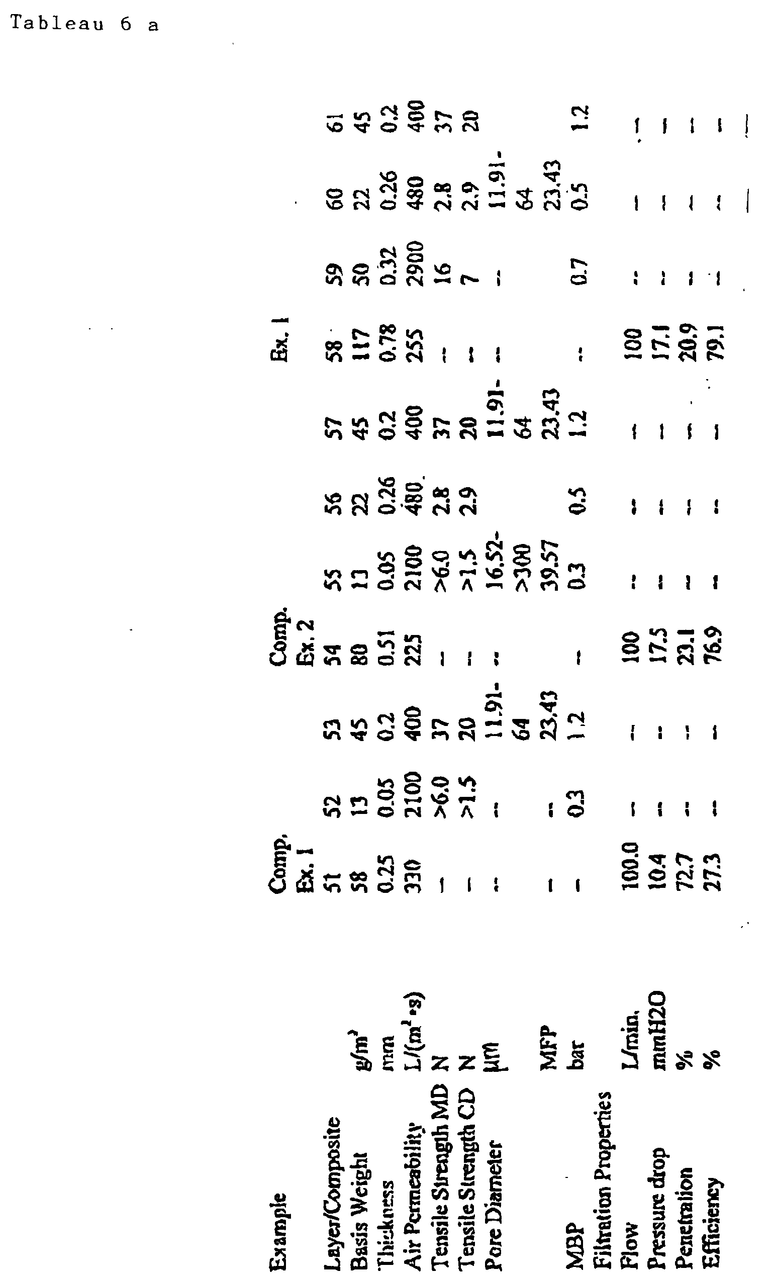
Example Ex.2 Ex.3 Layer/ Composite 62 63 64 65 66 67 Basis Weight g/ m 2122 77 45 110 65 45 Thickness mm 1.14 0.94 0.2 1.11 0.91 0.2 Air Permeability L/(m2·s) 420 1850 400 330 3000 400 Tensile Strength MD N -- 6.1 37 -- 5.8 37 Tensile Strength CD N -- 5.4 20 -- 5.2 20 Pore Diameter µm -- -- 11.91- -- -- 11.91- 64 -- -- 64 MFP 23.43 -- -- 23.43 MBP bar -- -- 1.2 -- -- 1.2 Filtration Properties Flow L/min. 100 -- -- 100 -- -- Pressure drop mmH2O 12.90 -- -- 10.20 -- -- Penetration % 66.90 -- -- 27.30 -- -- Efficiency % 33.10 -- -- 72.70 -- -- 
- All publications including patents referred to herein are incorporated herein by reference. While the invention has been fully and amply described for one of average skill in the pertinent art, it should be understood that various substitutions and modifications which bring about substantially equivalent or superior results and/or performance are within the scope and the spirit of the following claims.


Claims (51)
- A disposable vacuum cleaner bag comprising a coarse filter laye comprising at least one of (a) a wet-laid high capacity paper, (b) a dry-laid high capacity paper, (c) a high bulk meltblown nonwoven, (d) a Spunblown (Modular) nonwoven, (e) a microdenier spunbond nonwoven positioned upstream in the direction of air flow of a filtration grade meltblown fleece
- The bag of claim 1 in which the filtration grade meltblown fleece layer has a basis weight of about 10-50 g/m2 and air permeability of about 100-1500 L/(m2x s).
- The bag of claim 2 in which the wet-laid high dust capacity paper has a basis weight of about 30-150 g/m2, air permeability of about 500-8000 L/(m2x s)and pore size of at least about 160 µm, the dry-laid high dust capacity paper has a basis basis weight of about 30-150 g/m2 and air permeability of about 500-8000 L/(m2x s)and the high bulk meltblown nonwoven has a basis weight of about 30-180 g/m2 and air permeability of about 300-8000 L/(m2x s).
- The bag of claim 1 further comprising downstream of the filtration grade meltblown fleece layer at least one outer layer comprising at least one of the following (i) a spunbond, wet-laid, dry-laid or hydroentangled nonwoven or netting having a basis weight of about 6-80 g/m2 and air permeability of about 500-10,000 L/(m2x s), and (ii) an odor absorbing composite comprising an activated carbon fiber layer having a basis weight of about 25-500 g/m2 and air permeability of about 500-3000 L/(m2x s)upstream of a backing layer of fleece having a basis weight of about 15-100 g/m2 and air permeability of about 2000-5000 L/(m2x s)
- The bag of claim 1 further comprising a support layer upstream of the filtration grade meltblown fleece layer.
- The bag of claim 5 in which the support layer is a spunbond nonwoven.
- The bag of claim 5 in which the support layer is upstream of the coarse filter layer and is one of the following (i) a netting scrim bonded to the coarse filter layer or (ii) a wet-laid tissue fleece.
- The bag of claim 1 in which at least one layer is of a material of suitable dielectric properties and which is electrostatically charged.
- The bag of claim 1 in which at least one layer is bonded to an adjacent layer of the bag.
- The bag of claim 9 in which the bonded layers are bonded with a porous hot melt adhesive.
- The bag of claim 9 in which all adjacent layers are bonded.
- The bag of claim 1 further comprising an odor absorbing composite upstream of the filtration grade meltblown fleece layer, the composite comprising an activated carbon fiber layer having a basis weight of about 25-500 g/m2 and air permeability of about 500-3000 L/(m2x s) downstream of a backing layer of fleece having a basis weight of about 15-100 g/m2 and air permeability of about 2000-5000 L/m2 /s.
- The bag of claim 4 in which the outer layer is spunbond nonwoven having a basis weight of about 10-40 g/m2, and the coarse filter layer is high bulk meltblown nonwoven having a basis weight of about 30-180 g/m2.
- The bag of claim 4 in which the outer layer is spunbond nonwoven having a basis weight of about 10-40 g/m2 and the coarse filter layer is a wet-laid high dust capacity paper having air permeability of about 500-8000 L/(m2x s).
- The bag of claim 4 in which the outer layer is spunbond nonwoven having a basis weight of about 10-40 g/m2 and the coarse filter layer is a dry-laid high dust capacity paper having air permeability of about 500-8000 L/(m2x s).
- The bag of claim 1 in which the dry-laid high capacity paper comprises bicomponent fibers having a sheath of one polymer and a core of a different polymer having a melting point higher than the one polymer.
- The bag of claim 16 in which the bicomponent fibers comprise about 25-50% of the dry-laid high dust capacity paper.
- The bag of claim 16 in which the core is polypropylene and the sheath is polyethylene.
- The bag of claim 16 in which the core is disposed eccentric relative to the sheath.
- The bag of claim 16 in which the bicomponent fibers have one polymer alongside the different polymer.
- The bag of claim 1 in which the high bulk meltblown nonwoven is electrostatically charged.
- A filter for removing particles entrained in a gas comprising a coarse filter layer comprising at least one of (a) a wet-laid high capacity paper, (b) a dry-laid high capacity paper, (c) a high bulk meltblown nonwoven, (d) a Spunblown (Modular) nonwoven, and (e) a microdenier spunbond nonwoven positioned upstream in the direction of air flow of a filtration grade meltblown fleece layer.
- The filter of claim 22 further comprising downstream of the filtration grade meltblown fleece layer at least one outer layer comprising one of the following (i) a nonwoven scrim of spunbond, wet-laid, dry-laid or hydroentangled fabric having a weight of about 6-80 g/m2 and air permeability of about 500-12,000 L/(m2x s), and (ii) an odor absorbing composite comprising an activated carbon fiber layer having a weight of about 25-500 g/m2 and air permeability of about 500-3000 L/m2 /s upstream of a backing layer of fleece having a weight of about 15-100 g/m2 and air permeability of about 2000-5000 L/m2 /s.
- A method of filtering a gas comprising passing a gas entrained with particles through a filter comprising a coarse filter layer comprising at least one of (a) a wet-laid high capacity paper, (b) a dry-laid high capacity paper, (c) a high bulk meltblown nonwoven, (d) a Spunblown (Modular) nonwoven, and (e) a microdenier spunbond nonwoven positioned upstream in the direction of air flow of a filtration grade meltblown fleece layer.
- The method of claim 24 in which the filter further comprising downstream of the filtration grade meltblown fleece layer at least one outer layer comprising one of the following (i) a nonwoven scrim of spunbond, wet-laid, dry-laid or hydroentangled fabric having a weight of about 6-80 g/m2 and air permeability of about 500-12,000 L/(m2x s), and (ii) an odor absorbing composite comprising an activated carbon fiber layer having a weight of about 25-500 g/m2 and air permeability of about 500-3000 L/(m2x s) upstream of a backing layer of fleece having a weight of about 15-100 g/m2 and air permeability of about 2000-5000 L/(m2x s).
- 26. A composite structure for a disposable vacuum cleaner bag comprising a multipurpose filtration capacity layer positioned upstream in the direction of air flow of a second filtration layer, the second filtration layer being selected from among (a) a wet-laid or a dry-laid filter having a base weight of about 30-100 g/m2 and air permeability of about 100-3000 L/(m2 x s) and (b) thermally bonded nonwoven having a basis weight of about 10-100 g/m2 and a permeability of about 100-3000 L/(m2 x s).
- The composite structure of claim 27 in which the multipurpose filtration capacity layer is selected from among:(a) a wet-laid or a dry-laid high dust capacity paper having a basis weight of about 30-150 g/m2 and air permeability of about 500-8000 L/(m2 x s);(b) high bulk meltblown nonwoven having a basis weight of about 30-180 g/m2 and an air permeability of about 300-1500 L/(m2 x s);(c) Spunblown Modular paper having a basis weight of a bout 20-150 g/m2 and an air permeability of about 200-3000 L/(m2 x s); and(d) microdiener spunbond nonwoven having a basis weight of about 20-150 g/m2 and an air permeability of about 500-10,000 L/(m2 x s).
- The composite structure of claim 26 in which the multipurpose filtration layer is operative to provide to the composite structure a pressure drop of at most 30 mbar at fine dust particle loading of at least 6.5 grams determined by DIN 44956-2.
- The composite structure of claim 27 in which the wet-laid high dust capacity paper comprises fibers comprising at least 15% chargeable or unchargeable synthetic fiber and a complementary amount of wood pulp fibers, and binder
- The composite structure of claim 29 in which the synthetic fibers are polyester.
- The composite structure of claim 29 in which the synthetic fibers are polyolefin fibers.
- The composite structure of claim 31 in which the polyolefin fibers are electrostatically charged polypropylene.
- The composite structure of claim 26 in which the multipurpose filtration layer comprises a dry-laid, high dust capacity paper of composition selected from among (a) latex bonded fluff pulp fibers, (b) thermally bondable fusing fibers, (c) a thermally bonded blend of thermally bondable fusing polymer fibers and fluff pulp fibers, (d) a thermally bonded blend of thermally bondable fusing fibers, fluff pulp fibers and split film fibers, (e) thermally bonded blend of mixed electrostatic fibers.
- The composite structure of claim 33 in which thermally bondable fusing fibers are bicomponent polymer fibers.
- The composite structure of claim 34 in which the bicomponent polymer fibers are polyolefin.
- The composite structure of claim 35 in which the bicomponent polymer fibers have a core of polypropylene and a sheath of polyethylene.
- The composite structure of claim 34 in which the bicomponent polymer fibers have a core disposed eccentrically relative to a sheath.
- The composite structure of claim 37 in which the core is positioned alongside the sheath.
- The composite structure of claim 33 in which the split film fibers are electrostatically charged
- The composite structure of claim 26 further comprising a meltblown fleece layer having a basis weight of about 10-50 g/m2 and an air permeability of about 100-1500 L/(m2 x s) positioned between the multipurpose filtration layer and the second filtration layer.
- The composite structure of claim 40 in which the meltblown fleece layer is electrostatically charged.
- The composite structure of claim 26 in which the thermally bonded nonwoven is the most downstream layer of the structure.
- The composite structure of claim 26 in which at least two adjacent layers of the structure are bonded.
- The composite structure of claim 43 in which the two bonded adjacent layers are the multipurpose filtration layer and the second filtration layer.
- The composite structure of claim 43 in which all adjacent layers of the structure are bonded.
- The bag of claim 26 in which the high bulk meltblown nonwoven is electrostatically charged.
- The composite structure of claim 26 in which at least one of the layers is of a chargeable material and the chargeable layer is electrostatically charged.
- A filter for removing particles entrained in a gas comprising a multipurpose filtration capacity layer positioned upstream in the direction of air flow of a second filtration layer, the second filtration layer being selected from among (a) a wet-laid or a dry-laid filter having a base weight of about 30-100 g/m2 and air permeability of about 100-3000 L/(m2 x s) and (b) thermally bonded nonwoven having a basis weight of about 10-100 g/m2 and a permeability of about 100-3000 L/(m2 x s).
- The filter of claim 48 in which the multipurpose filtration capacity layer is selected from among:(a) a wet-laid or a dry-laid high dust capacity paper having a basis weight of about 30-150 g/m2 and air permeability of about 500-8000 L/(m2 x s);(b) high bulk meltblown nonwoven having a basis weight of about 30-180 g/m2 and an air permeability of about 300-1500 L/(m2 x s);(c) Spunblown Modular paper having a basis weight of a bout 20-150 g/m2 and an air permeability of about 200-3000 L/(m2 x s); and(d) microdiener spunbond nonwoven having a basis weight of about 20-150 g/m2 and an air permeability of about 500-10,000 L/(m2 x s).
- A method of filtering a gas comprising passing a gas entrained with particles trough a composite structure comprising a multipurpose filtration capacity layer positioned upstream in the direction of air flow of a second filtration layer, the second filtration layer being selected from among (a) a wet-laid or a dry-laid filter having a base weight of about 30-100 g/m2 and air permeability of about 100-3000 L/(m2 x s) and (b) thermally bonded nonwoven having a basis weight of about 10-100 g/m2 and a permeability of about 100-3000 L/(m2 x s).
- The method of claim 50 in which the multipurpose filtration capacity layer is selected from among:(a) a wet-laid or a dry-laid high dust capacity paper having a basis weight of about 30-150 g/m2 and air permeability of about 500-8000 L/(m2 x s);(b) high bulk meltblown nonwoven having a basis weight of about 30-180 g/m2 and an air permeability of about 300-1500 L/(m2 x s);(c) Spunblown Modular paper having a basis weight of a bout 20-150 g/m2 and an air permeability of about 200-3000 L/(m2 x s); and(d) microdiener spunbond nonwoven having a basis weight of about 20-150 g/m2 and an air permeability of about 500-10,000 L/(m2 x s).
Priority Applications (4)
| Application Number | Priority Date | Filing Date | Title |
|---|---|---|---|
| DE29924781U DE29924781U1 (en) | 1998-05-11 | 1999-05-11 | Vacuum cleaner bag and improved vacuum cleaner bag |
| EP02018932A EP1258277B1 (en) | 1998-05-11 | 1999-05-11 | Vacuum cleaner bag |
| DE29924466U DE29924466U1 (en) | 1998-05-11 | 1999-05-11 | Vacuum cleaner bags and improved vacuum cleaner bags |
| DE29924771U DE29924771U1 (en) | 1998-05-11 | 1999-05-11 | Vacuum cleaner bag and improved vacuum cleaner bag |
Applications Claiming Priority (10)
| Application Number | Priority Date | Filing Date | Title |
|---|---|---|---|
| US8503298P | 1998-05-11 | 1998-05-11 | |
| US85032P | 1998-05-11 | ||
| US9603998P | 1998-08-11 | 1998-08-11 | |
| US96039P | 1998-08-11 | ||
| US10614398P | 1998-10-29 | 1998-10-29 | |
| US106143P | 1998-10-29 | ||
| US09/306,880 US6183536B1 (en) | 1998-05-11 | 1999-05-07 | Enhanced performance vacuum cleaner bag and method of operation |
| US306883 | 1999-05-07 | ||
| US306880 | 1999-05-07 | ||
| US09/306,883 US6171369B1 (en) | 1998-05-11 | 1999-05-07 | Vacuum cleaner bag construction and method of operation |
Related Child Applications (1)
| Application Number | Title | Priority Date | Filing Date |
|---|---|---|---|
| EP02018932A Division EP1258277B1 (en) | 1998-05-11 | 1999-05-11 | Vacuum cleaner bag |
Publications (3)
| Publication Number | Publication Date |
|---|---|
| EP0960645A2 true EP0960645A2 (en) | 1999-12-01 |
| EP0960645A3 EP0960645A3 (en) | 2000-02-02 |
| EP0960645B1 EP0960645B1 (en) | 2003-08-27 |
Family
ID=27536388
Family Applications (1)
| Application Number | Title | Priority Date | Filing Date |
|---|---|---|---|
| EP99401164A Revoked EP0960645B1 (en) | 1998-05-11 | 1999-05-11 | Vacuum cleaner bag or filter, and method of filtering a gas |
Country Status (19)
| Country | Link |
|---|---|
| EP (1) | EP0960645B1 (en) |
| JP (1) | JP2002514447A (en) |
| CN (2) | CN1306451A (en) |
| AT (2) | ATE253393T1 (en) |
| AU (1) | AU753631B2 (en) |
| BR (1) | BR9910389A (en) |
| CA (1) | CA2331636A1 (en) |
| CZ (1) | CZ20004184A3 (en) |
| DE (2) | DE69910660T2 (en) |
| DK (2) | DK1258277T3 (en) |
| HU (1) | HU224280B1 (en) |
| IL (1) | IL139539A0 (en) |
| MX (1) | MXPA00011001A (en) |
| NO (2) | NO322853B1 (en) |
| NZ (1) | NZ507746A (en) |
| PL (2) | PL194345B1 (en) |
| PT (2) | PT960645E (en) |
| TR (1) | TR200003335T2 (en) |
| WO (1) | WO1999058041A2 (en) |
Cited By (74)
| Publication number | Priority date | Publication date | Assignee | Title |
|---|---|---|---|---|
| WO2000062899A1 (en) * | 1999-04-19 | 2000-10-26 | Filterwerk Mann+Hummel Gmbh | Multilayer filter element |
| WO2002018693A2 (en) * | 2000-08-31 | 2002-03-07 | Kimberly-Clark Worldwide, Inc. | Integrated nonwoven laminate material |
| EP1199094A1 (en) | 2000-10-16 | 2002-04-24 | FiberMark Gessner GmbH & Co. | Dust filter bag with highly porous support layer |
| DE10109304A1 (en) * | 2001-02-26 | 2002-09-12 | Sandler C H Gmbh | Structured, voluminous metblown fleece |
| EP1362627A1 (en) * | 2002-05-16 | 2003-11-19 | Branofilter Gmbh | Multilayer filter structure and use of multilayer structure |
| US6669761B2 (en) | 2001-04-24 | 2003-12-30 | Carl Freudenberg Kg | Air filter having electrostatically active nonwoven fabric inliners and their use |
| EP1415699A1 (en) * | 2002-12-06 | 2004-05-06 | Eurofilters N.V. | Filter medium for a vacuum cleaner bag |
| EP1495709A1 (en) | 1999-01-07 | 2005-01-12 | Vorwerk & Co. Interholding GmbH | Dust filter bag for a vacuum cleaner and filter chamber or dust collection compartment |
| WO2005007275A1 (en) * | 2003-07-07 | 2005-01-27 | Reemay, Inc. | Wetlaid-spunbond laminate membrane support |
| DE102005054903B3 (en) * | 2005-11-17 | 2007-03-22 | Fibermark Gessner Gmbh & Co. | Dust filter bag, especially for vacuum cleaners, has an inflow layer with a filtration layer bonded to the outflow side of it in at least a three-layer structure for the separation of fine and coarse dust |
| EP1787564A2 (en) | 2005-11-22 | 2007-05-23 | Eurofilters Holding N.V | Holding plate with a deflection device for a vacuum cleaner dust bag |
| EP1787560A1 (en) | 2005-11-22 | 2007-05-23 | Eurofilters Holding N.V | Vacuum cleaner dust bag with deflection device |
| EP1787561A1 (en) | 2005-11-22 | 2007-05-23 | Eurofilters Holding N.V | Vacuum cleaner dust bag with closure means |
| US20080032579A1 (en) * | 2004-04-06 | 2008-02-07 | Jean-Claude Abed | Spunbond Fleece of Polymer Fibers and Its Use |
| CN100379482C (en) * | 2002-12-06 | 2008-04-09 | 欧洲过滤股份有限公司 | Nonwoven layer for a filter and filter medium |
| DE202006018863U1 (en) * | 2006-12-12 | 2008-04-17 | Mann+Hummel Gmbh | Filter element with activated carbon coating |
| EP1917895A1 (en) | 2006-11-03 | 2008-05-07 | Eurofilters Holding N.V | Vacuum cleaner filter bag |
| DE202006018865U1 (en) * | 2006-12-12 | 2008-05-15 | Mann+Hummel Gmbh | Multilayer filter element |
| DE202008005050U1 (en) | 2008-03-07 | 2008-06-26 | Eurofilters Holding N.V. | Vacuum cleaner filter bag |
| DE202007018375U1 (en) | 2007-07-06 | 2008-07-03 | Eurofilters Holding N.V. | Vacuum cleaner filter bag |
| DE202007018376U1 (en) | 2007-07-06 | 2008-07-03 | Eurofilters Holding N.V. | Vacuum cleaner filter bag |
| WO2009010408A1 (en) * | 2007-07-16 | 2009-01-22 | Nv Bekaert Sa | A filter medium |
| DE202006020701U1 (en) | 2006-12-15 | 2009-07-02 | Eurofilters Holding N.V. | Vacuum cleaner filter bag comprising a guide device |
| US7582142B2 (en) | 2004-03-01 | 2009-09-01 | Eurofilters N.V. | Absorbing agent, dust collection chamber and method for adsorbing odours |
| EP1050331B2 (en) † | 1999-05-06 | 2010-03-03 | Neenah Gessner GmbH | Double- or multilayered filtration material for air filtration and filter element made thereof |
| EP1982626A3 (en) * | 2007-04-20 | 2010-04-14 | Wolf PVG GmbH & Co. Kommanditgesellschaft | Bag for a vacuum cleaner for multiple uses |
| US7744680B2 (en) | 2003-12-19 | 2010-06-29 | Eurofilters N.V. | Vacuum-cleaner bag and method for extending the service life of vacuum-cleaner bags |
| EP2201874A1 (en) * | 2008-12-17 | 2010-06-30 | Wolf PVG GmbH & Co. KG | Vacuum cleaner bag and vacuum cleaner |
| EP2006009A3 (en) * | 2007-06-11 | 2010-10-27 | Johns Manville Europe GmbH | Filter medium |
| EP2263507A1 (en) | 2009-06-19 | 2010-12-22 | Eurofilters N.V. | Flat bag for a vacuum cleaner |
| EP2263508A1 (en) | 2009-06-19 | 2010-12-22 | Eurofilters N.V. | Flat bag for a vacuum cleaner with at least two diffusers |
| DE202010013622U1 (en) | 2010-09-27 | 2010-12-23 | Sandler Ag | Multi-layer filter construction |
| EP2266450A1 (en) | 2009-06-24 | 2010-12-29 | Eurofilters N.V. | Block bottom filter bag for vacuum cleaners |
| EP2311358A1 (en) | 2009-10-19 | 2011-04-20 | Eurofilters Holding N.V. | Holding plate for a vacuum cleaner filter bag |
| WO2011047765A1 (en) | 2009-10-19 | 2011-04-28 | Eurofilters Holding N.V. | Vacuum cleaner filter bag |
| WO2011047764A1 (en) | 2009-10-19 | 2011-04-28 | Eurofilters Holding N.V. | Vacuum cleaner filter bag |
| EP2366320A1 (en) | 2010-03-19 | 2011-09-21 | Eurofilters Holding N.V. | Vacuum cleaner filter bag |
| US8070858B2 (en) | 2005-12-12 | 2011-12-06 | Eurofilters N.V. | Filter bag for a vacuum cleaner and use thereof |
| US8092562B2 (en) | 2006-04-25 | 2012-01-10 | Eurofilters Holding N.V. | Holding plate for a vacuum cleaner filter bag |
| WO2012025451A1 (en) | 2010-08-23 | 2012-03-01 | Fiberweb Corovin Gmbh | Nonwoven web and fibers with electret properties, manufacturing processes thereof and their use |
| EP2433695A1 (en) | 2010-09-27 | 2012-03-28 | Sandler AG | Multilayer filter structure |
| US8152879B2 (en) | 2006-04-13 | 2012-04-10 | Eurofilters N.V. | Filter bag for a vacuum cleaner and also use thereof |
| DE102010049425A1 (en) * | 2010-10-23 | 2012-04-26 | Gea Heat Exchangers Gmbh | Nonwoven storage filter, useful for general room and process air technology, preferably for bag filters of air conditioners, comprises fibers of polyolefin and/or polyester |
| EP2502536A1 (en) | 2011-03-22 | 2012-09-26 | Jan Schultink | Ecologically efficient device for vacuum cleaning |
| WO2012126613A1 (en) | 2011-03-22 | 2012-09-27 | Eurofilters Holding N.V. | Vacuuming device comprising a vacuum cleaner and a bag filter |
| US8382871B2 (en) | 2005-11-22 | 2013-02-26 | Eurofilters Holding N.V. | Vacuum cleaner filter bag and use of said bag |
| US8449639B2 (en) | 2007-08-17 | 2013-05-28 | Eurofilters Holding N.V. | Vacuum cleaner filter bag |
| US8479356B2 (en) | 2005-11-22 | 2013-07-09 | Eurofilters Holding N.V. | Vacuum cleaner filter bag comprising a sealing device |
| EP2641523A1 (en) | 2012-03-22 | 2013-09-25 | Eurofilters Holding N.V. | Device for vacuum cleaning with a vacuum cleaning device and filter bag |
| DE102012010307A1 (en) * | 2012-05-24 | 2013-11-28 | Neenah Gessner Gmbh | Multilayer filter material of filter element for liquid filtration, has main portion that is provided with pre-filter layer, main filter layer and absolute hydrophilic or hydrophobic filter layer |
| EP2467196B1 (en) * | 2009-08-20 | 2014-01-08 | Heinrich Essers GmbH & Co. KG | Solids filter, in particular for a vacuum cleaner or an exhaust gas cleaning system |
| CN105120977A (en) * | 2013-03-15 | 2015-12-02 | 欧罗菲利特斯控股公司 | Vacuum cleaner filter bag |
| WO2015187206A1 (en) * | 2014-06-03 | 2015-12-10 | Shop Vac Corporation | Wet/dry vacuum bag |
| WO2015187205A1 (en) * | 2014-06-03 | 2015-12-10 | Shop Vac Corporation | Vacuum bag |
| DE10126425C5 (en) * | 2000-08-03 | 2017-04-20 | Branofilter Gmbh | filter bag |
| DE202009019156U1 (en) | 2009-06-19 | 2017-04-20 | Eurofilters N.V. | Flat bag for vacuum cleaner |
| EP3219236A1 (en) | 2016-03-17 | 2017-09-20 | Eurofilters Holding N.V. | Holding plate with improved closure |
| EP3219376A1 (en) | 2016-03-17 | 2017-09-20 | Eurofilters N.V. | Vacuum cleaner filter bag made from recycled plastics |
| EP3219374A1 (en) | 2016-03-17 | 2017-09-20 | Eurofilters N.V. | Vacuum cleaner filter bag made from recycled plastics |
| EP3219237A1 (en) | 2016-03-17 | 2017-09-20 | Eurofilters Holding N.V. | Holding plate with improved closure element |
| EP3219373A1 (en) | 2016-03-17 | 2017-09-20 | Eurofilters N.V. | Vacuum cleaner filter bag containing recycled textile materials and/or cotton linters |
| WO2017158026A1 (en) | 2016-03-17 | 2017-09-21 | Eurofilters N.V. | Vacuum-cleaner filter bag made from recycled plastic |
| EP3305155A1 (en) | 2016-10-06 | 2018-04-11 | Eurofilters N.V. | Vacuum cleaner filter bag containing recycled textile materials and/or cotton linters |
| DE202018102370U1 (en) | 2018-04-27 | 2018-05-04 | Eurofilters Holding N.V. | Vacuum cleaner filter bag with foil in the area of the holding plate |
| EP3354178A1 (en) | 2017-01-31 | 2018-08-01 | Eurofilters Holding N.V. | Floor vacuum cleaner |
| EP3357392A1 (en) | 2017-02-07 | 2018-08-08 | Eurofilters Holding N.V. | Holding plate for a vacuum cleaner dust bag with closure |
| DE202016008752U1 (en) | 2016-10-06 | 2019-06-17 | Eurofilters N.V. | Vacuum cleaner filter bag with recycled textile materials and / or cotton linters |
| EP3530170A1 (en) | 2018-02-23 | 2019-08-28 | Eurofilters Holding N.V. | Supporting plate with centring device |
| EP3530171A1 (en) | 2018-02-23 | 2019-08-28 | Eurofilters Holding N.V. | Holding plate with sealing element |
| EP3560402A1 (en) | 2018-04-27 | 2019-10-30 | Eurofilters Holding N.V. | Vacuum cleaner filter bag with film in the area of the holding plate |
| US10806316B2 (en) | 2016-03-17 | 2020-10-20 | Eurofilters Holding N.V. | Device for a vacuum cleaner filter bag with a holding device and a closure device |
| EP3824783A1 (en) * | 2019-11-20 | 2021-05-26 | Wolf PVG GmbH & Co. KG | Vacuum cleaner bag and method for manufacturing same |
| EP3909489A1 (en) * | 2020-05-13 | 2021-11-17 | Hilti Aktiengesellschaft | Disposal bag with pressure balancing matrix |
| WO2022029071A1 (en) | 2020-08-06 | 2022-02-10 | Eurofilters N.V. | Vacuum-cleaner filter bag made from recycled plastics |
Families Citing this family (24)
| Publication number | Priority date | Publication date | Assignee | Title |
|---|---|---|---|---|
| DE202005007503U1 (en) * | 2005-05-12 | 2006-09-21 | Melitta Haushaltsprodukte Gmbh & Co. Kg | filter bag |
| US8114183B2 (en) | 2005-09-20 | 2012-02-14 | Cummins Filtration Ip Inc. | Space optimized coalescer |
| US7828869B1 (en) | 2005-09-20 | 2010-11-09 | Cummins Filtration Ip, Inc. | Space-effective filter element |
| US7674425B2 (en) | 2005-11-14 | 2010-03-09 | Fleetguard, Inc. | Variable coalescer |
| US20070062886A1 (en) | 2005-09-20 | 2007-03-22 | Rego Eric J | Reduced pressure drop coalescer |
| US7959714B2 (en) | 2007-11-15 | 2011-06-14 | Cummins Filtration Ip, Inc. | Authorized filter servicing and replacement |
| DE102005049118B3 (en) * | 2005-10-14 | 2007-02-01 | Papierverarbeitung Görlitz GmbH | Dust filter bag for vacuum cleaner with a layer connected between two bag walls only in one direction |
| US8231752B2 (en) | 2005-11-14 | 2012-07-31 | Cummins Filtration Ip Inc. | Method and apparatus for making filter element, including multi-characteristic filter element |
| DE102008045683B4 (en) | 2008-09-04 | 2012-08-16 | Branofilter Gmbh | Dust filter bag device for a vacuum cleaner |
| DE102009006583A1 (en) * | 2009-01-29 | 2010-06-17 | Neenah Gessner Gmbh | Multi-layer filter material for liquid filtration, for manufacturing filter element, has three layers, where former layer is of wet fleece made of cellulose or synthetic fibers or mixture |
| DE202009003669U1 (en) * | 2009-03-17 | 2010-08-12 | Mann+Hummel Gmbh | filter element |
| DE102010007553A1 (en) * | 2009-05-14 | 2010-11-18 | Sms Siemag Ag | Filter fabric for a band filter |
| DE102010011512A1 (en) * | 2010-03-12 | 2011-09-15 | Mann+Hummel Gmbh | Filter medium of a filter element, filter element and method for producing a filter medium |
| CN102551604A (en) * | 2010-12-16 | 2012-07-11 | 莱克电气股份有限公司 | Dust bag for dust collector |
| JP5977525B2 (en) * | 2011-01-19 | 2016-08-24 | 株式会社Nbcメッシュテック | Surface filtration bag filter |
| DK2502535T3 (en) * | 2011-03-22 | 2014-01-27 | Eurofilters Holding Nv | Vacuum cleaner with vacuum cleaner and filter bag |
| DE102011086104A1 (en) * | 2011-11-10 | 2013-05-16 | Mahle International Gmbh | filter material |
| CN103211555B (en) * | 2012-01-19 | 2016-02-03 | 天佑电器(苏州)有限公司 | There is the dust catcher of high-temperature-resfilter filter system |
| CN103046231A (en) * | 2012-06-22 | 2013-04-17 | 浙江朝晖过滤技术股份有限公司 | Melt spinning non-woven material and production method and application thereof |
| JP6053486B2 (en) * | 2012-12-06 | 2016-12-27 | 株式会社ニフコ | filter |
| DE102015103019A1 (en) * | 2015-03-03 | 2016-09-08 | Vorwerk & Co. Interholding Gmbh | Dust pickup system with adsorbent material having Dämmschicht |
| AU2016254003A1 (en) * | 2015-04-30 | 2017-12-07 | Tti (Macao Commercial Offshore) Limited | A dust collection apparatus and a method of producing a dust collection apparatus |
| CN109306637A (en) * | 2017-07-26 | 2019-02-05 | 中轻特种纤维材料有限公司 | The manufacturing technology of high efficiency vacuum cleaner dust collecting sleeve paper |
| DE102018103682A1 (en) | 2018-02-19 | 2019-08-22 | Twe Gmbh & Co. Kg | filter media |
Citations (2)
| Publication number | Priority date | Publication date | Assignee | Title |
|---|---|---|---|---|
| US5080702A (en) | 1990-02-15 | 1992-01-14 | Home Care Industries, Inc. | Disposable two-ply filter |
| US5647881A (en) | 1995-04-20 | 1997-07-15 | Minnesota Mining And Manufacturing Company | Shock resistant high efficiency vacuum cleaner filter bag |
Family Cites Families (8)
| Publication number | Priority date | Publication date | Assignee | Title |
|---|---|---|---|---|
| DE3812849C3 (en) * | 1988-04-18 | 1996-03-21 | Gessner & Co Gmbh | Dust filter bag, its manufacture and use |
| US5753343A (en) * | 1992-08-04 | 1998-05-19 | Minnesota Mining And Manufacturing Company | Corrugated nonwoven webs of polymeric microfiber |
| US5730923A (en) * | 1992-09-28 | 1998-03-24 | The University Of Tennessee Research Corporation | Post-treatment of non-woven webs |
| DE19544790C2 (en) * | 1995-11-30 | 1998-11-26 | Kirchhoff International Gmbh M | Disposable vacuum cleaner bags |
| DE19606718A1 (en) * | 1996-02-23 | 1997-08-28 | Vorwerk Co Interholding | Multi-layer filter bag |
| US5672188A (en) * | 1996-05-28 | 1997-09-30 | Aaf International | High capacity filter media |
| US5817415A (en) * | 1996-09-12 | 1998-10-06 | E. I. Du Pont De Nemours And Company | Meltblown ionomer microfibers and non-woven webs made therefrom for gas filters |
| DE19731860C1 (en) * | 1997-07-24 | 1999-01-28 | Freudenberg Carl Fa | Dust filter bag |
-
1999
- 1999-05-11 PL PL99375457A patent/PL194345B1/en not_active IP Right Cessation
- 1999-05-11 MX MXPA00011001A patent/MXPA00011001A/en unknown
- 1999-05-11 DK DK02018932T patent/DK1258277T3/en active
- 1999-05-11 CZ CZ20004184A patent/CZ20004184A3/en unknown
- 1999-05-11 AT AT02018932T patent/ATE253393T1/en not_active IP Right Cessation
- 1999-05-11 NZ NZ507746A patent/NZ507746A/en not_active IP Right Cessation
- 1999-05-11 HU HU0104320A patent/HU224280B1/en not_active IP Right Cessation
- 1999-05-11 AT AT99401164T patent/ATE248014T1/en not_active IP Right Cessation
- 1999-05-11 PT PT99401164T patent/PT960645E/en unknown
- 1999-05-11 TR TR2000/03335T patent/TR200003335T2/en unknown
- 1999-05-11 EP EP99401164A patent/EP0960645B1/en not_active Revoked
- 1999-05-11 PL PL344661A patent/PL191581B1/en unknown
- 1999-05-11 BR BR9910389-3A patent/BR9910389A/en not_active Application Discontinuation
- 1999-05-11 DE DE69910660T patent/DE69910660T2/en not_active Revoked
- 1999-05-11 IL IL13953999A patent/IL139539A0/en unknown
- 1999-05-11 PT PT02018932T patent/PT1258277E/en unknown
- 1999-05-11 CA CA002331636A patent/CA2331636A1/en not_active Withdrawn
- 1999-05-11 JP JP2000547897A patent/JP2002514447A/en active Pending
- 1999-05-11 AU AU36235/99A patent/AU753631B2/en not_active Ceased
- 1999-05-11 DE DE69912653T patent/DE69912653T2/en not_active Revoked
- 1999-05-11 DK DK99401164T patent/DK0960645T3/en active
- 1999-05-11 WO PCT/IB1999/000896 patent/WO1999058041A2/en not_active Application Discontinuation
- 1999-05-11 CN CN99807584A patent/CN1306451A/en active Pending
- 1999-05-11 CN CNA2004100957207A patent/CN1618390A/en active Pending
-
2000
- 2000-11-08 NO NO20005639A patent/NO322853B1/en not_active Application Discontinuation
-
2006
- 2006-09-20 NO NO20064254A patent/NO20064254L/en unknown
Patent Citations (2)
| Publication number | Priority date | Publication date | Assignee | Title |
|---|---|---|---|---|
| US5080702A (en) | 1990-02-15 | 1992-01-14 | Home Care Industries, Inc. | Disposable two-ply filter |
| US5647881A (en) | 1995-04-20 | 1997-07-15 | Minnesota Mining And Manufacturing Company | Shock resistant high efficiency vacuum cleaner filter bag |
Cited By (179)
| Publication number | Priority date | Publication date | Assignee | Title |
|---|---|---|---|---|
| EP1495709A1 (en) | 1999-01-07 | 2005-01-12 | Vorwerk & Co. Interholding GmbH | Dust filter bag for a vacuum cleaner and filter chamber or dust collection compartment |
| WO2000062899A1 (en) * | 1999-04-19 | 2000-10-26 | Filterwerk Mann+Hummel Gmbh | Multilayer filter element |
| EP1050331B2 (en) † | 1999-05-06 | 2010-03-03 | Neenah Gessner GmbH | Double- or multilayered filtration material for air filtration and filter element made thereof |
| DE10126425C5 (en) * | 2000-08-03 | 2017-04-20 | Branofilter Gmbh | filter bag |
| WO2002018693A2 (en) * | 2000-08-31 | 2002-03-07 | Kimberly-Clark Worldwide, Inc. | Integrated nonwoven laminate material |
| WO2002018693A3 (en) * | 2000-08-31 | 2002-06-06 | Kimberly Clark Co | Integrated nonwoven laminate material |
| US6649547B1 (en) | 2000-08-31 | 2003-11-18 | Kimberly-Clark Worldwide, Inc. | Integrated nonwoven laminate material |
| DE10051186B4 (en) * | 2000-10-16 | 2005-04-07 | Fibermark Gessner Gmbh & Co. Ohg | Dust filter bag with highly porous carrier material layer |
| US6706086B2 (en) | 2000-10-16 | 2004-03-16 | Fibermark Gressner Gmbh & Co. Kg | Dust filter bag including a highly porous backing material ply |
| EP1199094A1 (en) | 2000-10-16 | 2002-04-24 | FiberMark Gessner GmbH & Co. | Dust filter bag with highly porous support layer |
| DE10109304B4 (en) * | 2001-02-26 | 2006-04-13 | Sandler Ag | Textured, voluminous metblown fleece |
| DE10109304A1 (en) * | 2001-02-26 | 2002-09-12 | Sandler C H Gmbh | Structured, voluminous metblown fleece |
| DE10109304C5 (en) * | 2001-02-26 | 2009-07-16 | Sandler Ag | Textured, voluminous metblown fleece |
| DE20221987U1 (en) | 2001-04-24 | 2009-12-31 | Carl Freudenberg Kg | Air filter with electrostatically effective nonwoven liners |
| US6669761B2 (en) | 2001-04-24 | 2003-12-30 | Carl Freudenberg Kg | Air filter having electrostatically active nonwoven fabric inliners and their use |
| DE20221979U1 (en) | 2001-04-24 | 2009-12-31 | Carl Freudenberg Kg | Air filter with electrostatically effective nonwoven liners |
| DE10120223B4 (en) * | 2001-04-24 | 2005-08-25 | Carl Freudenberg Kg | Multi-layer air filter and its use |
| US6966939B2 (en) | 2002-05-16 | 2005-11-22 | Branofilter Gmbh | Multi-layer filter structure and use of a multi-layer filter structure |
| DE10221694A1 (en) * | 2002-05-16 | 2003-12-04 | Branofilter Gmbh | Multi-layer filter structure and use of a multi-layer filter structure |
| EP1362627A1 (en) * | 2002-05-16 | 2003-11-19 | Branofilter Gmbh | Multilayer filter structure and use of multilayer structure |
| DE10221694B4 (en) | 2002-05-16 | 2018-07-12 | Branofilter Gmbh | Multi-layer filter construction, use of such a multi-layer filter assembly, dust filter bag, bag filter bag, pleated filter, surface exhaust filter and air filter for motor vehicles |
| US8080076B2 (en) | 2002-12-06 | 2011-12-20 | Eurofilters N.V. | Nonwoven layer for a filter and filter medium |
| WO2004052500A1 (en) * | 2002-12-06 | 2004-06-24 | Eurofilters N.V. | Nonwoven layer for a filter and filter medium |
| EP1415699A1 (en) * | 2002-12-06 | 2004-05-06 | Eurofilters N.V. | Filter medium for a vacuum cleaner bag |
| CN100379482C (en) * | 2002-12-06 | 2008-04-09 | 欧洲过滤股份有限公司 | Nonwoven layer for a filter and filter medium |
| US7051883B2 (en) | 2003-07-07 | 2006-05-30 | Reemay, Inc. | Wetlaid-spunbond laminate membrane support |
| US7470639B2 (en) | 2003-07-07 | 2008-12-30 | Fiberweb, Inc. | Production of wetlaid-spunbond laminate membrane support |
| WO2005007275A1 (en) * | 2003-07-07 | 2005-01-27 | Reemay, Inc. | Wetlaid-spunbond laminate membrane support |
| US7744680B2 (en) | 2003-12-19 | 2010-06-29 | Eurofilters N.V. | Vacuum-cleaner bag and method for extending the service life of vacuum-cleaner bags |
| US7582142B2 (en) | 2004-03-01 | 2009-09-01 | Eurofilters N.V. | Absorbing agent, dust collection chamber and method for adsorbing odours |
| US20080032579A1 (en) * | 2004-04-06 | 2008-02-07 | Jean-Claude Abed | Spunbond Fleece of Polymer Fibers and Its Use |
| DE102005054903B3 (en) * | 2005-11-17 | 2007-03-22 | Fibermark Gessner Gmbh & Co. | Dust filter bag, especially for vacuum cleaners, has an inflow layer with a filtration layer bonded to the outflow side of it in at least a three-layer structure for the separation of fine and coarse dust |
| EP1958561A2 (en) | 2005-11-22 | 2008-08-20 | Eurofilters Holding N.V | Vacuum cleaner filter bag |
| US8479356B2 (en) | 2005-11-22 | 2013-07-09 | Eurofilters Holding N.V. | Vacuum cleaner filter bag comprising a sealing device |
| US8157879B2 (en) | 2005-11-22 | 2012-04-17 | Eurofilters Holding N.V. | Vacuum cleaner filter bag with deflection device |
| EP1787560A1 (en) | 2005-11-22 | 2007-05-23 | Eurofilters Holding N.V | Vacuum cleaner dust bag with deflection device |
| EP1787561A1 (en) | 2005-11-22 | 2007-05-23 | Eurofilters Holding N.V | Vacuum cleaner dust bag with closure means |
| US8382871B2 (en) | 2005-11-22 | 2013-02-26 | Eurofilters Holding N.V. | Vacuum cleaner filter bag and use of said bag |
| EP1787564A2 (en) | 2005-11-22 | 2007-05-23 | Eurofilters Holding N.V | Holding plate with a deflection device for a vacuum cleaner dust bag |
| US8070858B2 (en) | 2005-12-12 | 2011-12-06 | Eurofilters N.V. | Filter bag for a vacuum cleaner and use thereof |
| US8152879B2 (en) | 2006-04-13 | 2012-04-10 | Eurofilters N.V. | Filter bag for a vacuum cleaner and also use thereof |
| US8092562B2 (en) | 2006-04-25 | 2012-01-10 | Eurofilters Holding N.V. | Holding plate for a vacuum cleaner filter bag |
| EP1917895A1 (en) | 2006-11-03 | 2008-05-07 | Eurofilters Holding N.V | Vacuum cleaner filter bag |
| US8066803B2 (en) | 2006-11-03 | 2011-11-29 | Eurofilters Holding N.V. | Vacuum cleaner filter bag |
| DE202006018863U1 (en) * | 2006-12-12 | 2008-04-17 | Mann+Hummel Gmbh | Filter element with activated carbon coating |
| DE202006018865U1 (en) * | 2006-12-12 | 2008-05-15 | Mann+Hummel Gmbh | Multilayer filter element |
| US8016123B2 (en) * | 2006-12-12 | 2011-09-13 | Mann & Hummel Gmbh | Filter element with active carbon coating |
| DE202006020701U1 (en) | 2006-12-15 | 2009-07-02 | Eurofilters Holding N.V. | Vacuum cleaner filter bag comprising a guide device |
| EP1982626A3 (en) * | 2007-04-20 | 2010-04-14 | Wolf PVG GmbH & Co. Kommanditgesellschaft | Bag for a vacuum cleaner for multiple uses |
| EP2006009A3 (en) * | 2007-06-11 | 2010-10-27 | Johns Manville Europe GmbH | Filter medium |
| US8852306B2 (en) | 2007-07-06 | 2014-10-07 | Eurofilters Holdings N.V. | Vacuum cleaner filter bag |
| DE202007018375U1 (en) | 2007-07-06 | 2008-07-03 | Eurofilters Holding N.V. | Vacuum cleaner filter bag |
| US8784525B2 (en) | 2007-07-06 | 2014-07-22 | Eurofilters Holding N.V. | Vacuum cleaner filter bag |
| DE202007018376U1 (en) | 2007-07-06 | 2008-07-03 | Eurofilters Holding N.V. | Vacuum cleaner filter bag |
| US8449642B2 (en) | 2007-07-16 | 2013-05-28 | Nv Bekaert Sa | Filter medium |
| WO2009010408A1 (en) * | 2007-07-16 | 2009-01-22 | Nv Bekaert Sa | A filter medium |
| US8449639B2 (en) | 2007-08-17 | 2013-05-28 | Eurofilters Holding N.V. | Vacuum cleaner filter bag |
| EP2098152A1 (en) | 2008-03-07 | 2009-09-09 | Eurofilters Holding N.V | Vacuum cleaner filter bag |
| DE202008005050U1 (en) | 2008-03-07 | 2008-06-26 | Eurofilters Holding N.V. | Vacuum cleaner filter bag |
| EP2201874A1 (en) * | 2008-12-17 | 2010-06-30 | Wolf PVG GmbH & Co. KG | Vacuum cleaner bag and vacuum cleaner |
| EP2201874B1 (en) | 2008-12-17 | 2016-06-29 | Wolf PVG GmbH & Co. KG | Vacuum cleaner bag and vacuum cleaner |
| US8702827B2 (en) | 2009-06-19 | 2014-04-22 | Eurofilters Holding N.V. | Flat bag for vacuum cleaners |
| EP2263508A1 (en) | 2009-06-19 | 2010-12-22 | Eurofilters N.V. | Flat bag for a vacuum cleaner with at least two diffusers |
| DE202010018626U1 (en) | 2009-06-19 | 2019-05-09 | Eurofilters N.V. | Flat bag for vacuum cleaner |
| EP3195782A1 (en) | 2009-06-19 | 2017-07-26 | Eurofilters N.V. | Sachet for a vacuum cleaner |
| EP2442702B1 (en) | 2009-06-19 | 2016-08-31 | Eurofilters N.V. | Flat bag for a vacuum cleaner |
| US8702828B2 (en) | 2009-06-19 | 2014-04-22 | Eurofilters Holding N. V. | Flat bag for vacuum cleaners |
| EP2263507A1 (en) | 2009-06-19 | 2010-12-22 | Eurofilters N.V. | Flat bag for a vacuum cleaner |
| DE202009019156U1 (en) | 2009-06-19 | 2017-04-20 | Eurofilters N.V. | Flat bag for vacuum cleaner |
| EP3443880A1 (en) | 2009-06-19 | 2019-02-20 | Eurofilters N.V. | Flat bag for a vacuum cleaner |
| DE202010018516U1 (en) | 2009-06-19 | 2017-07-13 | Eurofilters N.V. | Flat bag for vacuum cleaner |
| EP2266450A1 (en) | 2009-06-24 | 2010-12-29 | Eurofilters N.V. | Block bottom filter bag for vacuum cleaners |
| US8758465B2 (en) | 2009-06-24 | 2014-06-24 | Eurofilters Holding N.V. | Block-base bag for vacuum cleaners |
| EP2467196B1 (en) * | 2009-08-20 | 2014-01-08 | Heinrich Essers GmbH & Co. KG | Solids filter, in particular for a vacuum cleaner or an exhaust gas cleaning system |
| US8979961B2 (en) | 2009-10-19 | 2015-03-17 | Eurofilters Holding N.V. | Vacuum cleaner filter bag |
| US20120216493A1 (en) * | 2009-10-19 | 2012-08-30 | Jan Schultink | Vacuum Cleaner Filter Bag |
| WO2011047765A1 (en) | 2009-10-19 | 2011-04-28 | Eurofilters Holding N.V. | Vacuum cleaner filter bag |
| WO2011047763A1 (en) | 2009-10-19 | 2011-04-28 | Eurofilters Holding N.V. | Holding plate for a vacuum cleaner filter bag |
| WO2011047764A1 (en) | 2009-10-19 | 2011-04-28 | Eurofilters Holding N.V. | Vacuum cleaner filter bag |
| US10307030B2 (en) | 2009-10-19 | 2019-06-04 | Eurofilters Holding N.V. | Holding plate for a vacuum cleaner filter bag |
| EP2311358A1 (en) | 2009-10-19 | 2011-04-20 | Eurofilters Holding N.V. | Holding plate for a vacuum cleaner filter bag |
| US10188248B2 (en) | 2010-03-19 | 2019-01-29 | Eurofilters Holding N.V. | Vacuum cleaner filter bag |
| US10182691B2 (en) | 2010-03-19 | 2019-01-22 | Eurofilters Holding N.V. | Vacuum cleaner filter bag |
| US10178932B2 (en) | 2010-03-19 | 2019-01-15 | Eurofilters Holding N.V. | Vacuum cleaner filter bag |
| WO2011113544A2 (en) | 2010-03-19 | 2011-09-22 | Eurofilters Holding N.V. | Vacuum cleaner filter bag |
| EP2366320A1 (en) | 2010-03-19 | 2011-09-21 | Eurofilters Holding N.V. | Vacuum cleaner filter bag |
| EP2366321A1 (en) | 2010-03-19 | 2011-09-21 | Eurofilters Holding N.V. | Vacuum cleaner filter bag |
| WO2011113545A2 (en) | 2010-03-19 | 2011-09-22 | Eurofilters Holding N.V. | Vacuum cleaner filter bag |
| US10036107B2 (en) | 2010-08-23 | 2018-07-31 | Fiberweb Holdings Limited | Nonwoven web and fibers with electret properties, manufacturing processes thereof and their use |
| WO2012025451A1 (en) | 2010-08-23 | 2012-03-01 | Fiberweb Corovin Gmbh | Nonwoven web and fibers with electret properties, manufacturing processes thereof and their use |
| DE102010046567A1 (en) | 2010-09-27 | 2012-03-29 | Sandler Ag | Multi-layer filter construction |
| EP2433695A1 (en) | 2010-09-27 | 2012-03-28 | Sandler AG | Multilayer filter structure |
| DE202010013622U1 (en) | 2010-09-27 | 2010-12-23 | Sandler Ag | Multi-layer filter construction |
| DE102010049425A1 (en) * | 2010-10-23 | 2012-04-26 | Gea Heat Exchangers Gmbh | Nonwoven storage filter, useful for general room and process air technology, preferably for bag filters of air conditioners, comprises fibers of polyolefin and/or polyester |
| US9713409B2 (en) | 2011-03-22 | 2017-07-25 | Eurofilters N.V. | Ecologically efficient vacuuming device |
| WO2012126617A1 (en) | 2011-03-22 | 2012-09-27 | Jan Schultink | Ecologically efficient vacuuming device |
| US9877627B2 (en) | 2011-03-22 | 2018-01-30 | Eurofilters N.V. | Ecologically efficient vacuuming device |
| WO2012126613A1 (en) | 2011-03-22 | 2012-09-27 | Eurofilters Holding N.V. | Vacuuming device comprising a vacuum cleaner and a bag filter |
| EP2502536A1 (en) | 2011-03-22 | 2012-09-26 | Jan Schultink | Ecologically efficient device for vacuum cleaning |
| DE102011014682A1 (en) | 2011-03-22 | 2012-09-27 | Eurofilters Holding N.V. | Device for vacuuming with vacuum cleaner and filter bag |
| EP2502537A1 (en) | 2011-03-22 | 2012-09-26 | Jan Schultink | Ecologically efficient device for vacuum cleaning |
| WO2012126616A1 (en) | 2011-03-22 | 2012-09-27 | Jan Schultink | Ecologically efficient vacuuming device |
| EP3072430A1 (en) | 2012-03-22 | 2016-09-28 | Eurofilters Holding N.V. | Device for vacuum cleaning with a vacuum cleaning device and filter bag |
| EP2641523A1 (en) | 2012-03-22 | 2013-09-25 | Eurofilters Holding N.V. | Device for vacuum cleaning with a vacuum cleaning device and filter bag |
| US9402520B2 (en) | 2012-03-22 | 2016-08-02 | Eurofilters Holding N.V. | Vacuum cleaning apparatus having a vacuum cleaning unit and a filter bag |
| EP3072430B1 (en) | 2012-03-22 | 2017-05-10 | Eurofilters Holding N.V. | Device for vacuum cleaning with a vacuum cleaning device and filter bag |
| WO2013139552A1 (en) | 2012-03-22 | 2013-09-26 | Eurofilters Holding N.V. | Vacuum cleaning apparatus having a vacuum cleaning unit and a filter bag |
| DE102012010307B4 (en) * | 2012-05-24 | 2021-07-08 | Neenah Gessner Gmbh | Multi-layer filter material for liquid filtration and a filter element made from it |
| DE102012010307A1 (en) * | 2012-05-24 | 2013-11-28 | Neenah Gessner Gmbh | Multilayer filter material of filter element for liquid filtration, has main portion that is provided with pre-filter layer, main filter layer and absolute hydrophilic or hydrophobic filter layer |
| CN105120977A (en) * | 2013-03-15 | 2015-12-02 | 欧罗菲利特斯控股公司 | Vacuum cleaner filter bag |
| CN105120977B (en) * | 2013-03-15 | 2017-09-12 | 欧罗菲利特斯控股公司 | Vacuum cleaner bag |
| US10285549B2 (en) | 2014-06-03 | 2019-05-14 | Shop Vac Corporation | Wet/dry vacuum bag |
| CN106572774B (en) * | 2014-06-03 | 2020-04-10 | 肖普 Vac 公司 | Vacuum bag |
| WO2015187205A1 (en) * | 2014-06-03 | 2015-12-10 | Shop Vac Corporation | Vacuum bag |
| EP3563746A1 (en) * | 2014-06-03 | 2019-11-06 | Shop VAC Corporation | Vacuum bag |
| CN106413498B (en) * | 2014-06-03 | 2020-04-10 | 肖普 Vac 公司 | Wet/dry vacuum bag |
| EP3151713B1 (en) * | 2014-06-03 | 2021-06-02 | Shop VAC Corporation | Wet/dry vacuum bag |
| US11096537B2 (en) | 2014-06-03 | 2021-08-24 | Shop Vac Corporation | Vacuum bag |
| AU2015268876B2 (en) * | 2014-06-03 | 2019-11-21 | Shop Vac Corporation | Vacuum bag |
| CN106572774A (en) * | 2014-06-03 | 2017-04-19 | 肖普 Vac 公司 | Vacuum bag |
| EP3151713A1 (en) * | 2014-06-03 | 2017-04-12 | Shop VAC Corporation | Wet/dry vacuum bag |
| CN106413498A (en) * | 2014-06-03 | 2017-02-15 | 肖普 Vac 公司 | Wet/dry vacuum bag |
| US11013380B2 (en) | 2014-06-03 | 2021-05-25 | Shop Vac Corporation | Wet/dry vacuum bag |
| US10165919B2 (en) | 2014-06-03 | 2019-01-01 | Shop Vac Corporation | Vacuum bag |
| WO2015187206A1 (en) * | 2014-06-03 | 2015-12-10 | Shop Vac Corporation | Wet/dry vacuum bag |
| RU2706308C1 (en) * | 2016-03-17 | 2019-11-15 | Еврофильтерс Н.В. | Filtering bag for vacuum cleaner made of recycled plastic |
| EP3219376A1 (en) | 2016-03-17 | 2017-09-20 | Eurofilters N.V. | Vacuum cleaner filter bag made from recycled plastics |
| US11896922B2 (en) | 2016-03-17 | 2024-02-13 | Eurofilters N.V. | Vacuum cleaner filter bag with powdery and/or fibrous recycled material |
| US11602252B2 (en) | 2016-03-17 | 2023-03-14 | Eurofilters N.V. | Vacuum cleaner filter bag made from recycled plastic |
| US11504662B2 (en) | 2016-03-17 | 2022-11-22 | Eurofilters N.V. | Vacuum cleaner filter bag made from recycled plastic |
| DE212017000082U1 (en) | 2016-03-17 | 2018-10-18 | Eurofilters N.V. | Vacuum cleaner filter bag with dust and / or fibrous recycled material |
| DE212017000084U1 (en) | 2016-03-17 | 2018-10-26 | Eurofilters N.V. | Vacuum cleaner filter bag with dust and / or fibrous recycled material |
| DE212017000080U1 (en) | 2016-03-17 | 2018-10-26 | Eurofilters N.V. | Vacuum cleaner filter bags made of recycled plastics |
| EP3219376B1 (en) | 2016-03-17 | 2018-10-31 | Eurofilters N.V. | Vacuum cleaner filter bag made from recycled plastics |
| CN108882816A (en) * | 2016-03-17 | 2018-11-23 | 欧洲过滤袋公司 | The vacuum cleaber filter bag made of recycled plastic |
| EP3219377B1 (en) | 2016-03-17 | 2018-12-12 | Eurofilters N.V. | Vacuum cleaner filter bag containing dust and/or fibrous recycled material |
| AU2017232262B2 (en) * | 2016-03-17 | 2022-03-10 | Eurofilters N.V. | Vacuum-cleaner filter bag made from recycled plastic |
| CN109152968A (en) * | 2016-03-17 | 2019-01-04 | 欧罗菲利特斯公司 | The vacuum cleaner bag made of recycled plastic |
| CN109152968B (en) * | 2016-03-17 | 2022-01-18 | 欧罗菲利特斯公司 | Vacuum cleaner filter bag made of recycled plastic |
| EP3219236A1 (en) | 2016-03-17 | 2017-09-20 | Eurofilters Holding N.V. | Holding plate with improved closure |
| WO2017158025A3 (en) * | 2016-03-17 | 2017-11-09 | Eurofilters N.V. | Vacuum cleaner filter bag with recycled textile materials and/or cotton linters |
| WO2017158098A1 (en) | 2016-03-17 | 2017-09-21 | Eurofilters Holding N.V. | Retainer board with improved closure |
| WO2017158026A1 (en) | 2016-03-17 | 2017-09-21 | Eurofilters N.V. | Vacuum-cleaner filter bag made from recycled plastic |
| WO2017157820A1 (en) | 2016-03-17 | 2017-09-21 | Eurofilters N.V. | Vacuum cleaner filter bag comprising dust-like and/or fibre-like recycled material and/or seed fibres |
| WO2017157822A1 (en) | 2016-03-17 | 2017-09-21 | Eurofilters N.V. | Vacuum-cleaner filter bag made from recycled plastic |
| EP3219377A1 (en) | 2016-03-17 | 2017-09-20 | Eurofilters N.V. | Vacuum cleaner filter bag containing dust and/or fibrous recycled material |
| EP3219375A1 (en) | 2016-03-17 | 2017-09-20 | Eurofilters N.V. | Vacuum cleaner filter bag containing dust and/or fibrous recycled material |
| US10939788B2 (en) | 2016-03-17 | 2021-03-09 | Eurofilters Holding N.V. | Retaining plate with improved sealing |
| US10905299B2 (en) | 2016-03-17 | 2021-02-02 | Eurofilters Holding N.V. | Retaining plate with improved sealing |
| US10806316B2 (en) | 2016-03-17 | 2020-10-20 | Eurofilters Holding N.V. | Device for a vacuum cleaner filter bag with a holding device and a closure device |
| EP3666360A1 (en) | 2016-03-17 | 2020-06-17 | Eurofilters N.V. | Bicomponent fibre |
| EP3219374A1 (en) | 2016-03-17 | 2017-09-20 | Eurofilters N.V. | Vacuum cleaner filter bag made from recycled plastics |
| WO2017157827A1 (en) | 2016-03-17 | 2017-09-21 | Eurofilters N.V. | Vacuum-cleaner filter bag comprising dust-and/or fiber-like recycled material |
| WO2017158085A1 (en) | 2016-03-17 | 2017-09-21 | Eurofilters Holding N.V. | Holding board with an improved closure element |
| RU2706309C1 (en) * | 2016-03-17 | 2019-11-15 | Еврофильтерс Н.В. | Filtering bag for vacuum cleaner, containing recycled pulverized and/or fibrous material and/or seeds fibers |
| RU2706307C1 (en) * | 2016-03-17 | 2019-11-15 | Еврофильтерс Н.В. | Filtering bag for vacuum cleaner, containing recycled pulverized and/or fibrous material |
| EP3219373A1 (en) | 2016-03-17 | 2017-09-20 | Eurofilters N.V. | Vacuum cleaner filter bag containing recycled textile materials and/or cotton linters |
| EP3219237A1 (en) | 2016-03-17 | 2017-09-20 | Eurofilters Holding N.V. | Holding plate with improved closure element |
| EP3305155A1 (en) | 2016-10-06 | 2018-04-11 | Eurofilters N.V. | Vacuum cleaner filter bag containing recycled textile materials and/or cotton linters |
| US11678782B2 (en) | 2016-10-06 | 2023-06-20 | Eurofilters N.V. | Vacuum cleaner filter bags comprising recycled textile materials and/or cotton linters |
| WO2018065164A1 (en) | 2016-10-06 | 2018-04-12 | Eurofilters N.V. | Vacuum cleaner filter bag with recycled textile materials and/or cotton linters, and use |
| DE202016008752U1 (en) | 2016-10-06 | 2019-06-17 | Eurofilters N.V. | Vacuum cleaner filter bag with recycled textile materials and / or cotton linters |
| WO2018141438A1 (en) | 2017-01-31 | 2018-08-09 | Eurofilters Holding N.V. | Cylinder vacuum cleaner |
| EP3354178A1 (en) | 2017-01-31 | 2018-08-01 | Eurofilters Holding N.V. | Floor vacuum cleaner |
| EP3357392A1 (en) | 2017-02-07 | 2018-08-08 | Eurofilters Holding N.V. | Holding plate for a vacuum cleaner dust bag with closure |
| US11517163B2 (en) | 2017-02-07 | 2022-12-06 | Eurofilters Holding N.V. | Retaining plate for a vacuum cleaner filter bag, having a closure device |
| WO2018145937A1 (en) | 2017-02-07 | 2018-08-16 | Eurofilters Holding N.V. | Retaining plate for a vacuum-cleaner filter bag, having a closure device |
| EP3530170A1 (en) | 2018-02-23 | 2019-08-28 | Eurofilters Holding N.V. | Supporting plate with centring device |
| EP3530171A1 (en) | 2018-02-23 | 2019-08-28 | Eurofilters Holding N.V. | Holding plate with sealing element |
| WO2019162424A1 (en) | 2018-02-23 | 2019-08-29 | Eurofilters Holding N.V. | Retainer plate with a centering device |
| WO2019162307A1 (en) | 2018-02-23 | 2019-08-29 | Eurofilters Holding N.V. | Retainer plate with a seal element |
| DE202018102370U1 (en) | 2018-04-27 | 2018-05-04 | Eurofilters Holding N.V. | Vacuum cleaner filter bag with foil in the area of the holding plate |
| WO2019206532A1 (en) | 2018-04-27 | 2019-10-31 | Eurofilters Holding N.V. | Vacuum cleaner filter bag with film in the region of the holding plate |
| EP3560402A1 (en) | 2018-04-27 | 2019-10-30 | Eurofilters Holding N.V. | Vacuum cleaner filter bag with film in the area of the holding plate |
| EP3824783A1 (en) * | 2019-11-20 | 2021-05-26 | Wolf PVG GmbH & Co. KG | Vacuum cleaner bag and method for manufacturing same |
| EP3909489A1 (en) * | 2020-05-13 | 2021-11-17 | Hilti Aktiengesellschaft | Disposal bag with pressure balancing matrix |
| WO2021228566A1 (en) * | 2020-05-13 | 2021-11-18 | Hilti Aktiengesellschaft | Disposal bag having pressure equalization matrix |
| CN115397293A (en) * | 2020-05-13 | 2022-11-25 | 喜利得股份公司 | Disposal bag with pressure balancing matrix |
| WO2022029071A1 (en) | 2020-08-06 | 2022-02-10 | Eurofilters N.V. | Vacuum-cleaner filter bag made from recycled plastics |
Also Published As
Similar Documents
| Publication | Publication Date | Title |
|---|---|---|
| EP0960645B1 (en) | Vacuum cleaner bag or filter, and method of filtering a gas | |
| US6171369B1 (en) | Vacuum cleaner bag construction and method of operation | |
| CA2439300C (en) | Composite filter and method of making the same | |
| US6372004B1 (en) | High efficiency depth filter and methods of forming the same | |
| AU2002240938A1 (en) | Composite filter and method of making the same | |
| EP1258277A1 (en) | Vacuum cleaner bag | |
| JP5080041B2 (en) | Air filter medium, streamer filter using the same, and method for producing air filter medium | |
| EP1581327A1 (en) | Multilayer nonwovens incorporating differential cross-sections | |
| AU765699B2 (en) | Vacuum cleaner bag and improved vacuum cleaner bag | |
| NZ525778A (en) | Vacuum cleaner bag and improved vacuum cleaner bag | |
| JP3404796B2 (en) | Filter media | |
| JP2554259Y2 (en) | Filter cloth | |
| JPH11179121A (en) | Substrate for filter and filter comprising substrate for filter | |
| JPH0630869A (en) | Throwaway paper bag filter for vacuum cleaner | |
| ES2207137T3 (en) | BAG OR FILTER FOR VACUUM CLEANER AND PROCEDURE TO FILTER A GAS. | |
| DE29924500U1 (en) | Disposable filter bag for vacuum cleaners |
Legal Events
| Date | Code | Title | Description |
|---|---|---|---|
| PUAI | Public reference made under article 153(3) epc to a published international application that has entered the european phase |
Free format text: ORIGINAL CODE: 0009012 |
|
| AK | Designated contracting states |
Kind code of ref document: A2 Designated state(s): AT BE CH CY DE DK ES FI FR GB GR IE IT LI LU MC NL PT SE |
|
| AX | Request for extension of the european patent |
Free format text: AL;LT;LV;MK;RO;SI |
|
| RTI1 | Title (correction) |
Free format text: VACUUM CLEANER BAG OR FILTER, AND METHOD OF FILTERING A GAS |
|
| PUAL | Search report despatched |
Free format text: ORIGINAL CODE: 0009013 |
|
| AK | Designated contracting states |
Kind code of ref document: A3 Designated state(s): AT BE CH CY DE DK ES FI FR GB GR IE IT LI LU MC NL PT SE |
|
| AX | Request for extension of the european patent |
Free format text: AL;LT;LV;MK;RO;SI |
|
| RIN1 | Information on inventor provided before grant (corrected) |
Inventor name: SCHULTINK, JAN Inventor name: SCHULTINK, BAS |
|
| 17P | Request for examination filed |
Effective date: 19991202 |
|
| AKX | Designation fees paid |
Free format text: AT BE CH CY DE DK ES FI FR GB GR IE IT LI LU MC NL PT SE |
|
| 17Q | First examination report despatched |
Effective date: 20020508 |
|
| GRAH | Despatch of communication of intention to grant a patent |
Free format text: ORIGINAL CODE: EPIDOS IGRA |
|
| GRAS | Grant fee paid |
Free format text: ORIGINAL CODE: EPIDOSNIGR3 |
|
| GRAA | (expected) grant |
Free format text: ORIGINAL CODE: 0009210 |
|
| AK | Designated contracting states |
Designated state(s): AT BE CH CY DE DK ES FI FR GB GR IE IT LI LU MC NL PT SE |
|
| REG | Reference to a national code |
Ref country code: GB Ref legal event code: FG4D |
|
| REG | Reference to a national code |
Ref country code: CH Ref legal event code: EP |
|
| REG | Reference to a national code |
Ref country code: IE Ref legal event code: FG4D |
|
| REF | Corresponds to: |
Ref document number: 69910660 Country of ref document: DE Date of ref document: 20031002 Kind code of ref document: P |
|
| REG | Reference to a national code |
Ref country code: CH Ref legal event code: NV Representative=s name: ARNOLD & SIEDSMA AG |
|
| REG | Reference to a national code |
Ref country code: SE Ref legal event code: TRGR |
|
| REG | Reference to a national code |
Ref country code: DK Ref legal event code: T3 Ref country code: GR Ref legal event code: EP Ref document number: 20030404473 Country of ref document: GR |
|
| REG | Reference to a national code |
Ref country code: ES Ref legal event code: FG2A Ref document number: 2207137 Country of ref document: ES Kind code of ref document: T3 |
|
| PLBQ | Unpublished change to opponent data |
Free format text: ORIGINAL CODE: EPIDOS OPPO |
|
| ET | Fr: translation filed | ||
| PLBI | Opposition filed |
Free format text: ORIGINAL CODE: 0009260 |
|
| PLBQ | Unpublished change to opponent data |
Free format text: ORIGINAL CODE: EPIDOS OPPO |
|
| PLBI | Opposition filed |
Free format text: ORIGINAL CODE: 0009260 |
|
| PLAX | Notice of opposition and request to file observation + time limit sent |
Free format text: ORIGINAL CODE: EPIDOSNOBS2 |
|
| 26 | Opposition filed |
Opponent name: BRANOFILTER GMBH Effective date: 20040521 |
|
| 26 | Opposition filed |
Opponent name: CARL FREUDENBERG KG Effective date: 20040526 Opponent name: 3M INNOVATIVE PROPERTIES COMP.,3M GEN.OFFICES ST.P Effective date: 20040527 Opponent name: BRANOFILTER GMBH Effective date: 20040521 |
|
| PLAY | Examination report in opposition despatched + time limit |
Free format text: ORIGINAL CODE: EPIDOSNORE2 |
|
| NLR1 | Nl: opposition has been filed with the epo |
Opponent name: CARL FREUDENBERG KG Opponent name: 3M INNOVATIVE PROPERTIES COMP.,3M GEN.OFFICES ST.P Opponent name: BRANOFILTER GMBH |
|
| PLAY | Examination report in opposition despatched + time limit |
Free format text: ORIGINAL CODE: EPIDOSNORE2 |
|
| PLBB | Reply of patent proprietor to notice(s) of opposition received |
Free format text: ORIGINAL CODE: EPIDOSNOBS3 |
|
| PLBC | Reply to examination report in opposition received |
Free format text: ORIGINAL CODE: EPIDOSNORE3 |
|
| PLAQ | Examination of admissibility of opposition: information related to despatch of communication + time limit deleted |
Free format text: ORIGINAL CODE: EPIDOSDOPE2 |
|
| PLAR | Examination of admissibility of opposition: information related to receipt of reply deleted |
Free format text: ORIGINAL CODE: EPIDOSDOPE4 |
|
| PLBQ | Unpublished change to opponent data |
Free format text: ORIGINAL CODE: EPIDOS OPPO |
|
| PLAB | Opposition data, opponent's data or that of the opponent's representative modified |
Free format text: ORIGINAL CODE: 0009299OPPO |
|
| PLAT | Information related to reply to examination report in opposition deleted |
Free format text: ORIGINAL CODE: EPIDOSDORE3 |
|
| PLAY | Examination report in opposition despatched + time limit |
Free format text: ORIGINAL CODE: EPIDOSNORE2 |
|
| R26 | Opposition filed (corrected) |
Opponent name: CARL FREUDENBERG KG Effective date: 20040526 Opponent name: 3M INNOVATIVE PROPERTIES COMP.,3M GEN.OFFICES ST.P Effective date: 20040527 Opponent name: BRANOFILTER GMBH Effective date: 20040521 |
|
| NLR1 | Nl: opposition has been filed with the epo |
Opponent name: CARL FREUDENBERG KG Opponent name: 3M INNOVATIVE PROPERTIES COMP.,3M GEN.OFFICES ST.P Opponent name: BRANOFILTER GMBH |
|
| PLAP | Information related to despatch of examination report in opposition + time limit deleted |
Free format text: ORIGINAL CODE: EPIDOSDORE2 |
|
| RDAF | Communication despatched that patent is revoked |
Free format text: ORIGINAL CODE: EPIDOSNREV1 |
|
| APBP | Date of receipt of notice of appeal recorded |
Free format text: ORIGINAL CODE: EPIDOSNNOA2O |
|
| APAH | Appeal reference modified |
Free format text: ORIGINAL CODE: EPIDOSCREFNO |
|
| APBQ | Date of receipt of statement of grounds of appeal recorded |
Free format text: ORIGINAL CODE: EPIDOSNNOA3O |
|
| PGFP | Annual fee paid to national office [announced via postgrant information from national office to epo] |
Ref country code: MC Payment date: 20060505 Year of fee payment: 8 |
|
| PGFP | Annual fee paid to national office [announced via postgrant information from national office to epo] |
Ref country code: PT Payment date: 20060508 Year of fee payment: 8 |
|
| PGFP | Annual fee paid to national office [announced via postgrant information from national office to epo] |
Ref country code: GB Payment date: 20060510 Year of fee payment: 8 |
|
| PGFP | Annual fee paid to national office [announced via postgrant information from national office to epo] |
Ref country code: CY Payment date: 20060511 Year of fee payment: 8 |
|
| PGFP | Annual fee paid to national office [announced via postgrant information from national office to epo] |
Ref country code: IE Payment date: 20060512 Year of fee payment: 8 |
|
| PGFP | Annual fee paid to national office [announced via postgrant information from national office to epo] |
Ref country code: FR Payment date: 20060518 Year of fee payment: 8 |
|
| PGFP | Annual fee paid to national office [announced via postgrant information from national office to epo] |
Ref country code: ES Payment date: 20060519 Year of fee payment: 8 Ref country code: AT Payment date: 20060519 Year of fee payment: 8 |
|
| PGFP | Annual fee paid to national office [announced via postgrant information from national office to epo] |
Ref country code: LU Payment date: 20060522 Year of fee payment: 8 Ref country code: FI Payment date: 20060522 Year of fee payment: 8 Ref country code: DK Payment date: 20060522 Year of fee payment: 8 |
|
| PGFP | Annual fee paid to national office [announced via postgrant information from national office to epo] |
Ref country code: SE Payment date: 20060523 Year of fee payment: 8 Ref country code: NL Payment date: 20060523 Year of fee payment: 8 Ref country code: BE Payment date: 20060523 Year of fee payment: 8 |
|
| PGFP | Annual fee paid to national office [announced via postgrant information from national office to epo] |
Ref country code: CH Payment date: 20060526 Year of fee payment: 8 |
|
| PGFP | Annual fee paid to national office [announced via postgrant information from national office to epo] |
Ref country code: GR Payment date: 20060530 Year of fee payment: 8 |
|
| PGFP | Annual fee paid to national office [announced via postgrant information from national office to epo] |
Ref country code: IT Payment date: 20060531 Year of fee payment: 8 |
|
| PGFP | Annual fee paid to national office [announced via postgrant information from national office to epo] |
Ref country code: DE Payment date: 20060630 Year of fee payment: 8 |
|
| APBU | Appeal procedure closed |
Free format text: ORIGINAL CODE: EPIDOSNNOA9O |
|
| RDAG | Patent revoked |
Free format text: ORIGINAL CODE: 0009271 |
|
| STAA | Information on the status of an ep patent application or granted ep patent |
Free format text: STATUS: PATENT REVOKED |
|
| REG | Reference to a national code |
Ref country code: PT Ref legal event code: MP4A Effective date: 20071114 |
|
| 27W | Patent revoked |
Effective date: 20070323 |
|
| GBPR | Gb: patent revoked under art. 102 of the ep convention designating the uk as contracting state |
Free format text: 20070323 |
|
| REG | Reference to a national code |
Ref country code: CH Ref legal event code: PL |
|
| NLV4 | Nl: lapsed or anulled due to non-payment of the annual fee |
Effective date: 20071201 |
|
| REG | Reference to a national code |
Ref country code: SE Ref legal event code: ECNC |
|
| PLAB | Opposition data, opponent's data or that of the opponent's representative modified |
Free format text: ORIGINAL CODE: 0009299OPPO |