EP0959426A1 - A method of reconstructing successive scans of a bar code - Google Patents
A method of reconstructing successive scans of a bar code Download PDFInfo
- Publication number
- EP0959426A1 EP0959426A1 EP98830306A EP98830306A EP0959426A1 EP 0959426 A1 EP0959426 A1 EP 0959426A1 EP 98830306 A EP98830306 A EP 98830306A EP 98830306 A EP98830306 A EP 98830306A EP 0959426 A1 EP0959426 A1 EP 0959426A1
- Authority
- EP
- European Patent Office
- Prior art keywords
- elements
- scan
- block
- steps
- cluster
- Prior art date
- Legal status (The legal status is an assumption and is not a legal conclusion. Google has not performed a legal analysis and makes no representation as to the accuracy of the status listed.)
- Granted
Links
Images


Classifications
-
- G—PHYSICS
- G06—COMPUTING; CALCULATING OR COUNTING
- G06K—GRAPHICAL DATA READING; PRESENTATION OF DATA; RECORD CARRIERS; HANDLING RECORD CARRIERS
- G06K7/00—Methods or arrangements for sensing record carriers, e.g. for reading patterns
- G06K7/10—Methods or arrangements for sensing record carriers, e.g. for reading patterns by electromagnetic radiation, e.g. optical sensing; by corpuscular radiation
- G06K7/14—Methods or arrangements for sensing record carriers, e.g. for reading patterns by electromagnetic radiation, e.g. optical sensing; by corpuscular radiation using light without selection of wavelength, e.g. sensing reflected white light
- G06K7/1404—Methods for optical code recognition
- G06K7/146—Methods for optical code recognition the method including quality enhancement steps
- G06K7/1491—Methods for optical code recognition the method including quality enhancement steps the method including a reconstruction step, e.g. stitching two pieces of bar code together to derive the full bar code
-
- G—PHYSICS
- G06—COMPUTING; CALCULATING OR COUNTING
- G06K—GRAPHICAL DATA READING; PRESENTATION OF DATA; RECORD CARRIERS; HANDLING RECORD CARRIERS
- G06K7/00—Methods or arrangements for sensing record carriers, e.g. for reading patterns
- G06K7/10—Methods or arrangements for sensing record carriers, e.g. for reading patterns by electromagnetic radiation, e.g. optical sensing; by corpuscular radiation
- G06K7/14—Methods or arrangements for sensing record carriers, e.g. for reading patterns by electromagnetic radiation, e.g. optical sensing; by corpuscular radiation using light without selection of wavelength, e.g. sensing reflected white light
- G06K7/1404—Methods for optical code recognition
- G06K7/146—Methods for optical code recognition the method including quality enhancement steps
- G06K7/1465—Methods for optical code recognition the method including quality enhancement steps using several successive scans of the optical code
Definitions
- bar codes are optical codes containing coded information made up of a plurality of rectangular elements (bars) having a dark colour (normally black) separated by light elements (spaces, normally white).
- Reading devices for the said bar codes usually comprise an illumination device (e.g. a laser beam source) adapted to send an optical reading beam which moves along a scanning path intersecting the bar code and also comprise a sensor (e.g. a photodiode) which receives part of the diffused light from the portion of the scanning path illuminated by the laser spot.
- the sensor in response to the radiation falling on it as a result of scanning a bar code, outputs an alternating electric signal having a wave shape which is modulated by the succession of light and dark elements in the bar code.
- a signal generated by scanning the bar code is successively binarised and has a two-level wave shape which represents the elements of the bar code and comprises a first high level when scanning a space and a second low level when scanning a bar.
- Normally bar codes are examined in a scanning direction which does not coincide with the longitudinal axis of the code.
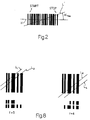
- the scanning direction is therefore usually at an angle to the longitudinal axis of the bar code. More particularly, when this angle exceeds a threshold value ⁇ max (Fig. 2), a subset of the code elements are scanned and the binarised signal, which relates to a partial scan of the bar code, comprises a subset of the code elements.
- Some known reconstruction devices are adapted to put together successive partial scans of the same code, made in different positions, in order to reconstruct and decode the bar code.
- Reconstruction devices of this kind which put together those elements of a partial scan which have a given inclination with respect to the longitudinal axis of the bar code, effect an omnidirectional readout of the code.
- the object of the invention is to provide a method of reconstructing successive partial scans of a bar code, featuring a particularly efficient omnidirectional reading of the code. Furthermore, object of the invention is to provide a method of reconstructing successive partial scans so as to efficiently manipulate the successive partial scans.
- the invention relates to a method of reconstructing successive scans of a bar code comprising a plurality of elements, said elements having a first and a second reflectivity and being represented by a position with respect to a reference position and by a width, characterised by the steps of: performing a first scan of the bar code, determining the position and the width of the elements in the first scan with respect to an absolute reference position; calculating the position which said elements in said first scan will take respect to said absolute reference position in a subsequent scan; making a second scan of the bar code, determining the position and the width of the elements in said second scan with respect to said absolute reference position; carrying out a correspondence search step to find at least one reference element in said first scan and one reference element in said second scan which both have substantially the same position with respect to said absolute reference and substantially the same width; and combining the elements in said first scan with the elements in said second scan so as to generate a reconstructed scan.
- said correspondence search step is followed by a coupling check step for checking that at least a predetermined number of elements in said first scan and said second scan have substantially the same position with respect to the absolute reference position and substantially the same width.
- the coupling check step is carried out by comparing at least one minimum defined set of elements in said first scan with a minimum defined set of elements in said second scan.
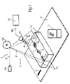
- reference number 1 indicates as a whole a bar code reading device comprising a reading head 5 facing a conveyor belt 6 and adapted to pick out objects 7 (e.g. packets) disposed on the belt 6 and movable in a rectilinear direction D at a constant speed with respect to the reading head 5.
- objects 7 e.g. packets
- One surface 7a of each object 7 facing the reading head 5 bears one or more optical codes 8, more particularly bar codes of known kind (Fig. 2).
- Each bar code is made up of a plurality of rectangular portions (bars) having varying reflectivity, more particularly dark (normally black) portions separated by light portions (spaces, normally white). Different dark and light portions (bars and spaces) can have different widths.
- a code "element” will mean a bar or a space of the code.
- Adjacent elements of the code together form a character of the code, to which coded information is associated.
- the reading head 5 comprises a known illumination device 17 (e.g. comprising a laser source 17a and a rotating prismatic mirror 17b adapted to reflect the laser beam produced by the source 17a), for directing a laser scanning beam F on to the optical codes 8 and scanning the codes 8.
- a known illumination device 17 e.g. comprising a laser source 17a and a rotating prismatic mirror 17b adapted to reflect the laser beam produced by the source 17a
- the laser beam F moves in a substantially inclined plane and intersects the belt 6 and the objects thereon along a scanning path L on which the laser spot moves from a beginning-of-scanning position Li to an end-of-scanning position Lf.
- the reading head 5 also comprises a sensor 20 (e.g. a photodiode) associated with an optical acquisition and focusing system 21 (diagrammatically represented) for picking up the diffused light radiation R in order to generate an output analog signal S(t) having an intensity proportional to the brightness of the portion of the path L which is being scanned at that moment.
- the analog signal S(t) is fed to an electronic unit 22 which processes the analog signal S(t) according to the invention.
- the unit 22 is also adapted to pick up the coded information associated with the code.
- the reading device described with reference to Fig. 1 is one example of the various reading devices which could be used in association with the method according to the invention; the device 1 could be of a different kind and could e.g. comprise a lamp or LEDs for illuminating the bar codes, or a telecamera or a CCD for picking up a grey-level bidimensional image of the bar codes and of the successive processing devices, which likewise output a signal S(t) having an intensity proportional to the brightness of a portion of a scanned bar code.
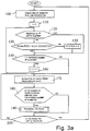
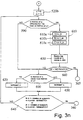
- Fig. 3a is a general block diagram of the operating cycle of an electronic processing unit 22.
- FIG. 3a proceeds from a starting block (START) to a block 100 which acquires the analog signal S(t) generated by the sensor 20 after a complete scan of scanning path L.
- a "complete scan” means a scan in which the laser spot moves from the beginning-of-scanning position Li to the end-of-scanning position LF.
- the analog signal S(t) typically has an initial portion corresponding to scanning the beginning-of-scanning position Li (Fig. 1), a final portion corresponding to scanning the end-of-scanning position Lf and an intermediate section which, corresponding to a scanned bar code, comprises an alternating section (shown in Fig. 4a) formed by a sequence of zones P having a high amplitude (peaks) separated by zones V of low amplitude (valleys).
- a peak P represents a space whereas a valley V represents a bar.
- the analog signal S(t) is then binarised in the block 100 and, corresponding to an alternating section thereof, outputs a signal Sd(t) having two levels (shown in Fig. 4b) comprising a first high level HI on scanning a space and a second low level LO on scanning a bar.
- the high levels HI and low levels LO of the signal Sd(t) are joined by substantially vertical transition fronts which separate the different-level portions of the signal Sd(t) and represent the separation zone between two different elements (bar-space) of the code.
- the wave form of the binarised signal Sd(t) is situated on a time axis having its origin (time to) at the instant when scanning begins, i.e. the instant at which the laser spot illuminates the beginning-of-scanning position Li.
- the beginning-of-scanning position Li is an absolute spatial reference to which the positions of the bar code elements are referred and consequently the instant to is taken as an absolute time reference with respect to which the positions in time of the code elements represented by the signal Sd(t) are measured.
- time Tp measured between the time origin to and an instant ti when a digitised signal front Sd(t) is present represents the time distance between the bar code element following the considered front and the absolute reference (to).
- the time width Tc of the high-level portion HI and/or low-level portion LO of the digitised signal Sd(t) represents the width of a bar code element.
- each bar code element is represented in the signal Sd(t) by a time interval Tp which represents the position of the bar code element with respect to the absolute reference (time to equivalent to the beginning-of-scanning position Li) and by a time interval Tc which represents the width of the code element.
- FRAME will mean a set of code elements as represented by the digitised signal Sd(t).
- each FRAME comprises a plurality of positions and widths representing the elements of the scanned bar code.
- a FRAME for example, can be represented by a table TABF (Fig. 9) in which:
- each CLUSTER means a storage area in which the FRAMES relating to a given bar code are stored, in the same order as the FRAMES themselves are acquired during successive scans as explained hereinafter.
- the CLUSTER elements are represented e.g. by a table TABC (Fig. 9) in which:
- the signal Sd(t) comprises a set of distinct different FRAMES F1, F2, ... Fn.
- a FRAME contains all the elements of a bar code only when the scan occurs along a line between the longitudinal axis H of the code and a line L' (Fig. 2) at an inclination less than or equal to ⁇ max with respect to the axis H.
- the objects 7 and the optical codes 8 thereon have an arbitrary relative arrangement with respect to the scanning path L. Consequently the scanning line normally intersects only a part of the bar code.
- each FRAME normally relates to scanning of a subgroup of the bar code elements (not of the entire bar code). Consequently each FRAME relates to a partial scan and represents the cited subgroup of elements.
- the successive FRAMES relating to scanning of the same code are grouped in a respective CLUSTER which can be individually selected on the basis of the value taken by a pointer i.
- STATUS 1 and STATUS 2 will be called active states, whereas STATUS 0 will be called inactive state.
- STATUS index of all the CLUSTERS will be zero.
- STATUS index of the CLUSTERS is modified (transferred to one of the two active states or set at zero) depending on the result of checks made on the CLUSTER itself or on the result of attempts to couple each CLUSTER to the extracted FRAMES as described in detail. Consequently, active CLUSTERS and inactive CLUSTERS will generally be present at every moment.
- Each CLUSTER is also marked by a second index called NOMATCH which represents the number of failed attempts made to associate additional FRAMES to the same CLUSTER.
- the block 110 is followed by a block 120 which selects the i th CLUSTER and checks the status of the first STATUS index associated with this i th CLUSTER. More particularly the block 120 checks whether the STATUS index of the 1 th CLUSTER is an active state, i.e.:
- the block 130 re-selects the i th CLUSTER and checks the value of the second NOMATCH index; more particularly if the NOMATCH index is equal to or above a threshold value MAX-NOMATCH, i.e. if at least MAX-NOMATCH failed attempts have been made to associate the i th CLUSTER with additional FRAMES, block 130 will select a block 150 for forcing to zero the first STATUS index of the i th CLUSTER which at present is active, i.e.:
- active CLUSTERS for which at least MAX-NOMATCH failed attempts have been made to associate them with new FRAMES are transferred to the inactive state, i.e. cancelled and made available for storing FRAME elements which cannot be associated with active CLUSTERS.
- the block 170 is adapted in known manner to select a single FRAME Fi from the signal Sd(t) relating to a complete scan.
- the block 170 is followed by a block 180 adapted to count the number Nf of elements of the FRAME Fi previously selected, i.e. the number of bar code elements represented by the FRAME. If the number Nf is above a minimum number of elements defining a threshold value, the block 180 is followed by a block 190, otherwise the block 180 is followed by a block 200.
- the block 190 (described in detail hereinafter) selected when the FRAME Fi comprises a number of elements above the minimum number of elements is adapted to process the FRAME, i.e. is adapted to try to associate the FRAME Fi with each active CLUSTER.
- the block 190 is in any case followed by the block 200, which checks whether the FRAME Fi under examination is the last FRAME contained in the scan detected by the block 100. If not, a return is made from block 200 to block 170 in order to select another FRAME Fi + 1, or otherwise (after examination of the FRAMES in the scan) a return is made from block 200 to block 100 in order to acquire another scan. In the other scan, of course, the objects 7 will be in a different position from the preceding scan and consequently different portions of the bar code will be scanned and FRAMES will be detected relating to partial scans of the codes made in different successive positions from the positions in the preceding scan.
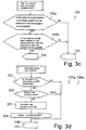
- Fig. 3b gives a detailed view of the block 190 adapted to process the FRAME Fi extracted from the block 170. The process consists in attempting to associate the FRAME Fi with all the active CLUSTERS present in the memory.
- the block 190 comprises a block 191 adapted to select a first CLUSTER.
- the block 191 is followed by a block 192 which checks whether the selected CLUSTER is the last CLUSTER present in the memory. If not so (other CLUSTERS are present in the memory) the block 190 selects a block 193, otherwise (after examination of the CLUSTERS present in the memory) the block 192 selects a block 194.
- the block 193 checks whether the selected CLUSTER is an active CLUSTER; if so (the selected CLUSTER is active) the block 193 is followed by a block 195, otherwise (the selected CLUSTER is inactive) a return is made from block 193 to block 191.
- the block 195 (described in detail hereinafter) checks whether the FRAME Fi and the selected CLUSTER intersect, i.e. whether the FRAME and the CLUSTER comprise elements which have comparable positions when superposed.
- block 195 If the check of the block 195 gives a negative result (the FRAME Fi and the CLUSTER do not intersect) a return is made from block 195 to block 191. Otherwise (the FRAME Fi and the CLUSTER intersect and can be combined) the block 195 is followed by a block 196.
- the block 196 modifies a state index of the FRAME, by putting it in a state indicating the use made of the FRAME. Indeed this use is made subsequently during the next attempt to combine the FRAME Fi with the various active CLUSTERS.
- the block 196 is followed by a block 197 which checks whether the FRAME Fi has already been decoded; if not (no attempt has yet been made to decode the FRAME) the block 197 is followed by a block 197a which attempts this decoding. Otherwise (the FRAME has already been decoded) the block 197 is followed by a block 198.
- the fact that the FRAME has been successfully decoded in block 197a means that this FRAME comprises all the elements of the bar code; in that case it is of course unnecessary to reconstruct the successive partial scans. The decoded code is therefore transmitted to the exterior of the unit 22.
- the block 198 (described in detail hereinafter) tries to combine the FRAME Fi with a first active CLUSTER; if the attempt has a negative result, the contents of a counter measuring the NOMATCH number of failed combination attempts made by the CLUSTER is incremented by one unit and the block 198 is followed by the block 191 for selecting another active CLUSTER and repeating the effort to combine the same FRAME Fi with the additional CLUSTER.
- the block 198 is followed by a block 198a which tries to decode the CLUSTER to which the FRAME Fi has been successfully added. If the CLUSTER is successfully decoded, the decoded code is transmitted to the exterior of the unit 22.
- the block 198a is likewise followed by the block 191.
- the block 194 checks the value of the state index of the FRAME Fi indicative of its use. If the index indicates that the FRAME Fi has been subjected to a combination attempt with at least one active CLUSTER, a transition is made from block 194 to block 200 (Fig. 3a) for selecting (block 170) an additional FRAME Fi + 1 which will be subjected to the operations in block 190 described with reference to Fig. 3b. If the state index of the FRAME indicates that the FRAME Fi has not yet been subjected to a combination attempt, the block 194 is followed by a block 194a (described in detail hereinafter) which initialises a CLUSTER by inserting the FRAME Fi into it. The block 194a is likewise followed by the block 200.
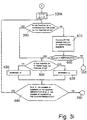
- Fig. 3c shows details of the block 195 which checks whether the FRAME Fi and the selected CLUSTER intersect and are therefore superposable.
- the block 195 comprises a first block 195a which checks whether the position Tfl (Fig. 7) of the last element in the FRAME with respect to the absolute reference (the beginning-of-scanning position corresponding to the time to) is lower than the position TCf of the first element of the CLUSTER with respect to the absolute reference, i.e. Tfl ⁇ TCf
- the block 195b checks whether the position TFf of the first element in the FRAME with respect to the absolute reference is higher than the position TCl of the last element in the CLUSTER with respect to the absolute reference, i.e.: TCl ⁇ TFf
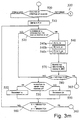
- Fig. 3d illustrates the blocks 197a or 198a, which try to decode the FRAME (or the CLUSTER).
- the block 197a, 198a comprises an initial block 201 which checks whether the length of the FRAME (or the CLUSTER) is acceptable for a bar code, i.e. whether it contains a number of elements compatible with a bar code.
- the block 201 is followed by the block 198 (or 191), otherwise the block 201 is followed by a block 202.
- the block 202 tries to decode the FRAME (or the CLUSTER) in a manner known per se, e.g. as described in US-A-3 723 710, US-A-3 761 685 or US-A-3 838 251. Decoding the frame in block 202 is sufficient in those fortunate cases where the entire code is read from the first scans. In such cases it is impossible to couple the FRAME to the relevant CLUSTER a second time (as explained in detail hereinafter with reference to block 400 in Fig.
- the block 202 is followed by the block 198 (or 191), or otherwise (the FRAME or CLUSTER is decoded successfully) the block 202 is followed by a block 203.
- the block 203 transmits the contents of decoding the FRAME (or CLUSTER) to the exterior of the unit 22, thus decoding the bar code.
- the block 203 is followed by a block 204 which indicates that the FRAME (or CLUSTER) has been decoded.
- the block 204 is followed by block 198 (or 191).
- Block 194a which initialises a CLUSTER.
- Block 194a comprises an initial block 206 for checking whether there is a synchronism character in the FRAME under examination. If the check by block 206 is positive, a transition is made to a block 207, otherwise the block 206 is followed by block 200.
- the block 208 is followed by the block 200.
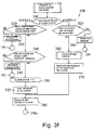
- Fig. 3f gives a detailed view of the block 198 which tries to associate a FRAME Fi with an active CLUSTER.
- the block 198 comprises an initial block 300 which controls the state index, variable between 1 and 2, of the CLUSTER.
- the CLUSTERS examined by block 300 are only active CLUSTERS, i.e. undoubtedly contain at least one FRAME in which a synchronism character is present.
- the block 300 selects a block 310 if a STATUS of 1 is detected, or a block 320 if a STATUS of 2 is detected.
- the block 310 checks whether the FRAME under examination contains a second synchronism character. If the check is negative, the block 310 is followed by a block 330 which cancels the CLUSTER by setting its state at zero, i.e. the CLUSTER is made inactive and the possible reconstruction is blocked. The block 330 is also followed by the block 191.
- reconstruction begins. Therefore, reconstruction begins only after detection of two successive FRAMES each containing a synchronism character.
- block 310 is followed by a block 340 (described in detail hereinafter) which checks for correspondence between the FRAME and the CLUSTER in order to check whether the FRAME and the CLUSTER belong to the same code.
- a block 340 (described in detail hereinafter) which checks for correspondence between the FRAME and the CLUSTER in order to check whether the FRAME and the CLUSTER belong to the same code.
- the block 340 then calculates the distance between the synchronism character of the FRAME and the corresponding synchronism character of the CLUSTER.
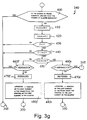
- the block 340 comprises an initial block 400 which checks whether the number of elements in the FRAME is greater than the number of elements in the CLUSTER. If this is not so, an error situation is detected and the block 400 is followed by block 345 and 191; otherwise the block 400 is followed by block 410.
- the check made in block 400 will prevent coupling between the actual FRAME and the CLUSTER and the situation will be as described hereinbefore with reference to block 197a in Fig. 3b.
- the block 410 is followed by a block 420 which calculates the number r of elements which are superposed in the FRAME and in the CLUSTER, i.e. which have the same position with respect to the absolute reference and the same width, starting the comparison from the last element of the FRAME and from the last element of the CLUSTER (corresponding to the right or REVERSE).
- the CLUSTER contains the code elements detected in the scan marked L1
- the FRAME contains the code elements found by the scan marked L2.
- the block 420 is followed by a block 430 which checks whether the number r is equal to the number f. If the numbers r and f are equal, an uncertainty situation is detected (the number of superposable elements on the right corresponds to the number of superposable elements on the left) and consequently the code is not reconstructed.
- the block 430 is followed by blocks 345 and 191. If the numbers r and f are different, the block 430 is followed by a block 440 which checks whether the number r or the number f is different from zero. If at least one of the said numbers is equal to zero, a non-correspondence situation is detected and consequently the code is not reconstructed. Blocks 430 and 440 are followed by blocks 345 and 191.
- a block 450 is selected which checks whether the number f is greater than the number r. If the number f is greater than the number r a block 460f is selected, otherwise (f is less than r) a block 460r is selected.
- the block 460r checks whether the number r of superposable elements starting from the right is greater than a threshold value MINIMATCH. If r is less than the threshold (i.e. if there are a limited number of corresponding elements in the FRAME and in the CLUSTER) an error is detected, reconstruction does not begin and the blocks 345 and 191 are selected. If r is above the MINMATCH threshold (i.e. when there is a sufficient number of superposed elements in the FRAME and in the CLUSTER) the block 460r selects a block 470r which stores the superposition condition starting from the right (BACKWARDS or REVERSE direction) of the bar code with respect to the reading head. The block 470r is followed by a block 480r which calculates the value ⁇ -position as the difference between the position of the last element in the FRAME and the position of the last element in the CLUSTER.
- a threshold value MINIMATCH i.e. if there are a limited number of corresponding elements in the FRAME
- the block 355 is followed by a block 380 which recalculates the position of the CLUSTER by disposing it in the position provided for the subsequent scan (due to the movement of the conveyor belt 6 (Fig. 1) and based on the measured displacement of the CLUSTER with respect to the just-associated FRAME.
- the block 380 is then followed by the block 198a.
- the CLUSTER taking part in the operations of block 320 is a CLUSTER which contains two FRAMES each comprising a synchronism character; the block 320 is normally selected during the third or fourth scan of the bar code.
- block 320 If the association attempted by block 320 is unsuccessful, block 320 is followed by a block 360 which increases by one unit the counter which defines the number NOMATCH; the block 360 is then followed by the block 191.
- block 320 If the association attempt by block 320 is successful, the block 320 is followed by a block 365 (described in detail hereinafter) which corrects the calculation of the distance ⁇ -position between the FRAME and the CLUSTER previously calculated in block 340 (Fig. 3g).
- Block 365 is followed by a block 370 (similar to block 355) which, after the operations performed by block 320, associates the new FRAME elements in the CLUSTER.
- the operations of block 370 will be described in detail hereinafter.
- Blocks 355 and 370 are followed by block 380, which in turn is followed by block 198a.
- Figs. 3h and 3i illustrate details of the block 320, which tries to associate the FRAME Fi with the CLUSTER under examination.
- the block 320 comprises an initial block 500 (Fig. 3h) which checks whether the bar code has made a FORWARD movement (block 460f, Fig. 3g) or a REVERSE movement (block 460r, Fig. 3g) with respect to the reading head.
- a block 510 is selected and in the second case (REVERSE movement) a block 520b is selected (Fig. 3i).
- the block 510 is followed by a block 520 which checks whether the position of element ic of the CLUSTER with respect to the absolute reference is approximately equal to the position of the element jn of the FRAME with respect to the same absolute reference.
- the block 530 checks whether the position of element ic in the CLUSTER is higher than the position of element jn in the FRAME.
- the block 555 decrements by unity the value of ic, i.e. performs the operation ic - 1, in order to select a CLUSTER element having a lower position than the preceding one.
- Blocks 555 and 550 are both followed by a block 560 which checks whether the values ic and jn (previously modified by the respective blocks 555 and 550) are now below a threshold value MINMATCH, i.e.: ic ⁇ MINMATCH or jn ⁇ MINMATCH
- block 560 is followed by block 360 (Figs. 3h and 3f) which detects an error situation and increases the number NOMATCH which describes the number of failed attempts at coupling between CLUSTERS and FRAMES.
- Block 540 performs the following operations:
- Block 540 is followed by a block 580 which checks whether the number A(ic, jn) is greater than the number MINMATCH, i.e.: A(ic,jn) > MINMATCH
- Fig. 3i The operations illustrated with reference to Fig. 3i are similar to those illustrated in Fig. 3h, but in this case the operations relate to the REVERSE direction of motion whereas the operations illustrated with reference to Fig. 3h are for the FORWARD direction of advance.
- block 590 is followed by block 600, otherwise (the position of the elements associated with ic and jn substantially coincide) block 590 is followed by a block 610.
- Block 600 checks whether the position of element ic in the CLUSTER is higher than the position of the FRAME element jn. If so (position of CLUSTER element ic > position of FRAME element jn), a block 620 is selected, otherwise, a block 630 is selected.
- Blocks 620 and 630 are both followed by a block 640 which checks whether the values of ic and jn (previously modified by the blocks 630 and 620 respectively) are now greater than the number of elements in the CLUSTER minus a threshold value MINMATCH, i.e.: ic > number of elements in the CLUSTER - MINMATCH or jn > number of elements in the CLUSTER - MINMATCH
- block 640 is followed by block 360 (Figs. 3i and 3f) which detects an error situation and increases the NOMATCH number, which describes the number of failed attempts at coupling CLUSTER and FRAME.
- block 640 is followed by block 590 which re-checks the position of the elements associated with ic and jn. The check is made on a different CLUSTER element or FRAME element from that used in the preceding check step.
- the block 610 is selected when the elements associated with ic and jn have substantially the same position and performs the following operations:
- Block 610 is followed by a block 660 which checks whether the number A(ic,jn) is greater than the number MINMATCH, i.e.: A(ic,jn) > MINMATCH
- the operations performed by block 320 define a correspondence search step in which a selection is made (blocks 510 and 520a) of an element (denoted by the pointer value ic, ic-1, ic+1) for beginning a check of the CLUSTER; a selection is made (blocks 510 and 520a) of a check start element (denoted by pointer value jn) of the FRAME and a corresponding check step is carried out (blocks 520 and 590) to check whether the position of the check start element in the CLUSTER with respect to the absolute reference is approximately the same as the position of the check start element of the FRAME with respect to the absolute reference.
- an iterative modification step is carried out (by blocks 530, 555, 559, 560; 600, 620, 630, 640) in order to select subsequent CLUSTER or FRAME elements adjoining the check start element.
- the iterative modification step is carried out by other CLUSTER or FRAME elements until the correspondence check step arrives at a positive result (output to blocks 540 and 610).
- a possible coupling between FRAME and CLUSTER is initially detected. Initially the coupling is detected in the case of a single element of the FRAME or the CLUSTER.
- a series of further operations are performed in the method according to the invention, including the following:
- the correspondence search operations start from the last-but-one element of the FRAME or the CLUSTER.
- the last FRAME or CLUSTER element is not selected, since it may provide information which is insufficiently reliable, e.g. because of noise.
- the last-but-one element is chosen because (see Fig. 8, scan L2) the last element may be only partly crossed by the scanning line, with the result that its width is uncertain.
- Fig. 3j shows the block 365, which recalculates the distance ⁇ -position between the FRAME and the CLUSTER.
- the distance ⁇ -position is calculated for the first time by block 340. More particularly, the block 365 recalculates the distance ⁇ -position as the difference between the position of FRAME element jn and CLUSTER element ic.
- ⁇ -position is initially calculated a first time in block 340 at the beginning of the coupling operations and is successively refined by calculation in block 365.
- Fig. 3m illustrates a variant of that described with reference to Fig. 3h. For simplicity, only the parts differing from those previously illustrated will be described.
- block 540 comprises a block 540a which performs the following operations:
- the block 540a is followed by block 540b, which performs the following operations:
- the block 540b is followed by the block 540c which performs the following operations:
- the block 540c (the last step in block 540) is followed by a block 570 which searches for the largest number Mb among the numbers A(ic,jn), B(ic-1,jn), c(ic+1,jn) which have previously been calculated in blocks 540a, 540b and 540c.
- the block 570 is followed by a block 580 which checks whether the previously-extracted number Mb is greater than a threshold value MINMATCH; if the check made by block 580 has given a negative result (Mb ⁇ MINMATCH) a return is made to block 520; if not (Mb>MINMATCH) a move is made from block 580 to block 365.
- block 365 recalculating the value ⁇ -position
- block 370 are selected (Fig. 3f), block 370 copying the FRAME elements following jn in the CLUSTER starting from the element ic, ic+1 or ic-1 depending on whether the selected greatest number is A(ic,jn), B(ic-1,jn) or C(ic+1,jn).
- block 610 comprises a block 610a which performs the following operations:
- the block 610b is followed by block 610c which performs the following operations:
- Block 650 is followed by a block 660 which checks whether the number Mf extracted by the previous block 650 is greater than the number MINMATCH, i.e.: Mf > MINMATCH
- block 660 is followed by blocks 365 and 370; if not (Mf ⁇ MINMATCH) block 660 is followed by block 600.
- the present method instead of being of the continuous kind and continually scanning and processing the code even after transmission of the decoded code (as described with reference to Fig. 3d, blocks 203, 204), can comprise interruption of the algorithm, setting the CLUSTER to zero and reactivation starting from block 100 only after manual actuation or after recognition of a subsequent code (e.g. after a period of scans without FRAMES). In such cases however it is advisable to insert a check that the number of elements in the FRAME or CLUSTER is equal to a given number of elements, so as to ensure that the code has actually been completely read.
Abstract
Description
- a first line comprises a number of cells each of which contains the position, with respect to the absolute reference to (time Tp), of an element of the FRAME and therefore represents the position of a bar code element; and
- a second line comprises a plurality of cells each of which contains the width (time Tc) of the corresponding FRAME element and consequently represents the width of a bar code element.
- a first row comprises a plurality of cells each of which contains the position, with respect to the absolute reference to (time Tp), of an element of the CLUSTER and therefore represents the position of a bar code element grouped in the CLUSTER; and
- a second row comprises a plurality of cells each of which contains the width (time Tc) of the corresponding element of the CLUSTER and therefore represents the width of a bar code element grouped in the CLUSTER.
- STATUS = 0 - the associated CLUSTER is empty, i.e. is not associated with any active data structure in which FRAMES can be grouped;
- STATUS = 1 - the associated CLUSTER contains a frame whereby a synchronism character, i.e. a START pattern or a STOP pattern, has been recognised for a first time; and
- STATUS = 2 - the CLUSTER contains at least two FRAMES whereby synchronism characters have been recognised.
- if the CLUSTER is marked by an inactive state index (STATUS = 0), the CLUSTER is not modified (i.e. no type of operation is performed); and
- if the CLUSTER is marked by an active state index (STATUS = 1, 2), the number of failed attempts to associate the said CLUSTER with additional frames is checked and, if the threshold value MAX-NOMATCH is exceeded, the CLUSTER is put in the inactive state by forcing to zero the STATUS index.
- select a plurality of CLUSTER elements starting from the element marked ic in the REVERSE direction towards elements (ic-1, ic-2, ... ic-n) preceding the said element ic. "Preceding elements" with respect to a given element mean elements having a lower position than the given element.
- select a plurality of FRAME elements starting from the element marked jn in the REVERSE direction towards elements (jn-1, jn-2, ... jn-m) preceding the considered element; and
- calculate the number A(ic,jn) of superposable elements by comparing at least MINMATCH selected elements in the CLUSTER and in the FRAME, starting from ic and jn. "Superposable elements" means a continuous sequence of elements of the FRAME and of the CLUSTER in which each element of the FRAME of the sequence corresponds to a respective element of the CLUSTER having the same position and the same width.
- it selects a plurality of CLUSTER elements starting from the element marked ic and in the FORWARD direction towards elements (ic+1, ic+2, ... ic+n) which follow the last element ic. "Elements which follow a given element" mean elements having a higher position than the given element.
- it selects a plurality of FRAME elements starting from the element marked jn and in the FORWARD direction towards elements (jn+1, jn+2, ... jn+m) following the last element jn and
- it calculates the number A(ic,jn) of superposable elements by comparing at least MINMATCH selected elements of the CLUSTER and the FRAME.
- selecting (
blocks 540, 610) a plurality of CLUSTER elements starting from the reference element which satisfies the correspondence check step in a predetermined direction (i.e. in the REVERSE or the FORWARD direction), starting from the reference element towards elements remote from the reference element; - selecting (
blocks 540, 610) a plurality of FRAME elements starting from the reference element (jn) which satisfies the correspondence check step and in a predetermined direction (the said REVERSE and FORWARD directions) starting from the reference element towards elements remote from the reference element; - calculating (
blocks 540, 610) the number of superposable elements among those selected in the CLUSTER and in the FRAME and - detecting (
blocks 580 and 660) that the correspondence search step has given a positive result when the number of superposable elements has a predetermined relation to (more particularly is greater than) the reference MINMATCH.
- it selects a plurality of CLUSTER elements starting from the element denoted by ic in the backward (REVERSE) direction towards elements (ic-1, ic-2, ... ic-n) preceding element ic. "Elements preceding a given element" means elements having a lower position than this element.
- is selects a plurality of FRAME elements starting from the element denoted by jn in the backward (REVERSE) direction towards element (jn-1, jn-2, ... jn-m) preceding this element and
- it calculates the number A(ic,jn) of superposable elements by comparing at least MINMATCH selected elements of the CLUSTER and of the FRAME starting from ic and jn. "Superposable elements" means a continuous sequence of elements of the FRAME and of the CLUSTER in which each FRAME element of the sequence corresponds to a respective CLUSTER element having the same position and the same width.
- it selects a plurality of CLUSTER elements starting from the element denoted by ic-1 in the backward (REVERSE) direction towards elements (ic-2, ic-3, ... ic-n) preceding element ic-1;
- it selects a plurality of FRAME elements starting from the element denoted by jn in the backward (REVERSE) direction towards elements (jn-1, jn-2, ... jn-m) preceding this element and
- it calculates the number B(ic-1,jn) of superposable elements by comparing at least MINMATCH selected elements of the CLUSTER and of the FRAME.
- it selects a plurality of CLUSTER elements starting from the element denoted by ic+1 in the backward (REVERSE) direction towards elements (ic, ic-1, ... ic-n) preceding element ic+1;
- it selects a plurality of FRAME elements starting from the element denoted by jn in the backward (REVERSE) direction towards elements (jn-1, jn-2, ... jn-m) preceding this element and
- it calculates the number C(ic+1,jn) of superposable elements by comparing at least MINMATCH selected elements of the CLUSTER and of the FRAME.
- it selects a plurality of CLUSTER elements starting from the element denoted by ic in the FORWARD direction towards elements (ic+1, ic+2, ... ic+n) following the last element ic. "Elements following a given element" means elements having a higher position than the given element.
- it selects a plurality of FRAME elements starting from the element denoted by jn in the FORWARD direction towards elements (jn+1, jn+2, ... jn+m) following the last element jn; and
- it calculates the number A(ic,jn) of superposable elements by comparing at least MINMATCH selected elements of the CLUSTER and of the FRAME.
- it selects a plurality of CLUSTER elements starting from the element denoted by ic-1 in the FORWARD direction towards elements (ic, ic+1, ... ic+n) following element ic-1;
- it selects a plurality of FRAME elements starting from the element denoted by jn in the FORWARD direction towards elements (jn+1, jn+2, ... jn+m) following element jn and
- it calculates the number B(ic-1,jn) of superposable elements by comparing at least MINMATCH selected elements of the CLUSTER and of the FRAME.
- it selects a plurality of CLUSTER elements starting from the element denoted by ic+1 in the FORWARD direction towards elements (ic+2, ic+3, ... ic+n) following element ic+1;
- it selects a plurality of FRAME elements starting from the element denoted by jn in the FORWARD direction towards elements (jn+1, jn+2, ... jn+m) following element jn and
- calculates the number C(ic+1,jn) of superposable elements by comparing at least MINMATCH selected elements of the CLUSTER and of the FRAME.
Claims (39)
- A method of reconstructing successive scans of a bar code (8) comprising a plurality of elements, said elements having a first and a second reflectivity and being represented by a width (Tc) and a position (Tp) with respect to a reference position (To, Li),
characterised by the steps of:a) performing (100) a first scan of the bar code, determining the position (Tp) and the width (Tc) of the elements in the first scan with respect to an absolute reference position (To, Li);b) calculating (380) the position which said elements in said first scan will take with respect to said absolute reference position in a subsequent scan;c) making (100) a second scan of the bar code, determining the position (Tp) and the width (Tc) of the elements in said second scan with respect to said absolute reference position (To, Li);d) carrying out a correspondence search step (510-530, 550-560; 520b, 590, 600, 620-640) in order to find (520, 590) at least one reference element in said first scan and at least one reference element in said second scan which both have substantially the same position (Tp) with respect to said absolute reference (To, Li) and substantially the same width (Tc); ande) combining (370) the elements in said first scan with the elements in said second scan so as to generate a reconstructed scan. - A method according to claim 1, characterised by the steps of:bb) calculating (380) the position said elements in said reconstructed scan will take with respect to said absolute reference position in a subsequent scan;cc) performing (100) a subsequent scan of the bar code, determining the position (Tp) and the width (Tc) of the elements in said subsequent scan with respect to said absolute reference position (To, Li);dd) carrying out a subsequent correspondence search step (510-530, 550-560; 520b, 590, 600, 620-640) to find (520, 590) at least one reference element in said reconstructed scan and at least one reference element in said subsequent scan which both have substantially the same position (Tp) with respect to said absolute reference position (To, Li) and substantially the same width (Tc); andee) updating (370) the elements in the reconstructed scan by combining them with the elements in said subsequent scan.
- A method according to claim 2, characterised by the steps of:bb1) calculating (380) the position which the elements in the reconstructed scan, after updating in step ee) will take with respect to said absolute reference position in a subsequent scan and
iteratively repeating said steps cc), dd), ee) and bb1) until (180) said subsequent scan comprises at least a predetermined number of elements. - A method according to claim 3, characterised in that only said step cc) is iteratively repeated as long as said subsequent scan comprises a number of elements less than the predetermined number.
- A method according to claim 2, characterised by the steps of:bb1) calculating (380) the position which the elements in the reconstructed scan, after updating in step ee), will take with respect to said absolute reference position in a subsequent scan;
attempting (198a) to decode said reconstructed scan; and iteratively repeating the steps cc), dd), ee) and bb1) as long as said step of attempting to decode gives a negative result. - A method according to any of the preceding claims, characterized in that said correspondence search step d) (320) is followed by a coupling check step f) (540, 570, 580; 610, 650, 660) for checking that at least a predetermined number (MINMATCH) of elements in said first scan and said second scan has substantially the same position (Tp) with respect to the absolute reference position (To) and substantially the same width (Tc).
- A method according to claim 6, characterized in that said coupling check step f) (540, 570, 580; 610, 650, 660) is carried out by comparing (540, 610) at least a defined minimum set (560, MINMATCH) of elements in said first scan with a minimum defined set (560, MINMATCH) of elements in said second scan.
- A method according to claim 6 or 7, characterised in that in said coupling check step f) a calculation (540; 610) is made of the number A(ic,jn) of superposable elements in said first and said second scan.
- A method according to claim 8, characterized in that said superposable elements are defined by a continuous sequence of elements in said first scan and said second scan having substantially the same position with respect to the absolute reference position and substantially the same width.
- A method according to any of claims 6-9, characterised in that said step e) of combining (370) the elements in said first scan with the elements in said second scan is carried out when said coupling check step f) (540, 570, 580; 610, 650, 660) has given a positive result.
- A method according to any of the preceding claims, characterized in that said correspondence check step d) comprises the steps of:d1) selecting (510; 520b) a check start element (ic) among the elements in said first scan and a check start element (jn) among the elements in said second scan;d2) carrying out a correspondence check step 520; 590) in order to check whether the position of the check start element in the second scan (520; 590) with respect to the absolute reference position is approximately the same as the position of the check start element in the first scan with respect to the absolute reference position;
if said correspondence check step d2) (520; 590) has given a negative result, carrying out an iterative modification stepd3) (530, 555, 550, 560; 600, 620, 630, 640) to select subsequent elements in the second scan or in the first scan adjacent to said check start element; the iterative modification step d3) is carried out with subsequent elements until said correspondence check step d2) arrives at a positive result (520; 590) and said reference element is found. - A method according to claim 11, characterized in that said check start element comprises a last-but-one element in the first and in the second scan.
- A method according to any of the preceding claims, characterized in that said correspondence search step d) is followed by a matching step g) (540a,b,c; 610a,b,c) for selecting a plurality of elements in said first scan and a plurality of elements in said second scan having better reciprocal superposability, said selected plurality of elements of the first and of the second scan being used in said step e) to generate said reconstructed scan.
- A method according to claim 13, characterized in that said matching step g) comprises at least the steps of:g1) selecting (540a, 610a) a first plurality of elements in the first scan starting from the reference element (ic) in the first scan and a second plurality of elements in the second scan starting from the reference element (jn) in the second scan;g2) calculating a first quantity (A) as an indication of superposition of elements in the first plurality and of elements in the second plurality;g3) selecting (540b, 610b) a third plurality of elements in the first scan starting from a first element (ic-1) in the first scan nearest the reference element (ic) in the first scan;g4) calculating a second quantity (B) indicating superposition of said elements in the second and in the third plurality;g5) comparing the first and second quantities and selecting (570) said first and second plurality if said first quantity indicates better superposability than said second quantity andg6) comparing said first and second quantity and selecting (570) said second and said third plurality if said second quantity indicates better superposability than said first quantity.
- A method according to claim 14, characterised by the further steps of:g7) selecting (540c, 610c) a fourth plurality of elements in the first scan starting from a second element (ic+1) in the first scan nearest the reference element (ic) in the first scan;g8) calculating a third quantity (C) indicating superposition of said elements in the second and in the fourth plurality andg9) comparing said first, second and third quantity and selecting (570) said second and fourth plurality if said third quantity indicates better superposability than said first and second quantity.
- A method according to claim 15, characterized in that said first and second element (ic-1, ic+1) in said first scan are adjacent said reference element (ic) in said first scan on two different sides thereof.
- A method according to any of claims 14-16, characterised in that said quantities comprise the number of elements in said first and said second scan which have substantially the same position with respect to the absolute reference position and substantially the same width and in that said steps for comparing said quantities comprise a search for the quantity which has the maximum value.
- A method according to any of claims 6-17, characterized in that said step e) of combining (370) the elements in the first scan with the elements in the second scan comprises the steps of:e1) selecting a first side of said reference element in said first scan comprising said elements in said first scan having substantially the same position and the same width as the elements in the second scan;e2) maintaining those elements in the first scan which are disposed on said first side ande3) adding to said first scan those elements in said second scan which are disposed on the side opposite said first side in order to generate said reconstructed scan.
- A method according to any of the preceding claims, characterized in that said step a) for carrying out (100) a first scan is preceded by the steps of:h) carrying out (100) a preliminary scan of said bar code by determining the position (Tp) and the width (Tc) of the elements in said preliminary scan with respect to said absolute reference position (To, Li) and associating the elements in said preliminary scan with a current area (FRAME); andi) associating (191, 194a) the elements in said current area (FRAME) with at least one of a plurality of loading areas (CLUSTERS).
- A method according to claim 19, characterized in that said association step i) comprises the steps of:i1) selecting (191) a loading area among said plurality of loading areas;i2) checking (193) whether the selected area is already occupied;i3a) if said selected area has not already been occupied, investigating (191, 192) whether a subsequent loading area exists;i4a) if a subsequent loading area exists, returning to said step i2) andi4b) if no subsequent loading area exists, copying (207) said elements in said current area into said unoccupied loading area, performing a first scan, associating the elements in said subsequent scan with said current area and returning to said step i1).
- A method according to claim 20, characterized in that said step i4b) comprises, before said step of copying (207), the step of searching for synchronism characters (206) between said elements in said current area (FRAME); if the search for synchronism characters in said current area gives a positive result and synchronism characters are found, a condition of presence of the first synchronism (208) is stored and said step of copying (207) is carried out; if the search for synchronism characters in said current area gives a negative result and no synchronism characters are found, said step of carrying out h) a preliminary scanning is repeated.
- A method according to claim 21, characterized in that said step i2) of checking (193) whether said selected area is already occupied comprises the step of checking whether said condition of presence of the first synchronism has been stored; if said condition of presence of the first synchronism is detected, the following step is carried out:i5) searching (310) for a synchronism character among the elements in said current area;i6a) if said step i5) of searching (310) gives a positive result and a synchronism character is found in said current area, the following steps are carried out: copying (355) the elements in said current area into said loading area; storing (350) a coupling condition; performing (100) a second scan, associating (170) the elements in said subsequent scan with said current area (FRAME) and returning to said step i1);i6b) if said search (310) step i5) gives a negative result and no synchronism character is found in said current area, cancelling (330) said condition of presence of a first synchronism and returning to said step h).
- A method according to claim 22, characterized in that said step i6a) of copying (355) and storing (350) is preceded by the steps of:i7) a coupling check (340) to verify whether the elements in said current area and the elements in said loading area can be coupled;i8a) if said elements in said current area and the loading area can be coupled, carrying out the steps i6a) of copying (355) and storing (350) a coupling condition;i8b) if said elements in said current area and the loading area cannot be coupled, updating (345) a failed-attempts counter.
- A method according to claim 23, characterized in that said coupling check (340) step i7) comprises the steps of:i7-1) checking (400) whether the number of elements in said current area has a predetermined relation to the number of elements in the loading area;i7-2a) if said checking (400) step i7-1) gives a positive result, calculating (410, 420) the number of superposable elements between said loading area and said current area;i7-3) checking (460f, 460r) whether the number of superposable elements exceeds a predetermined threshold value;i7-4a) if said step i7-3) gives a positive result, carrying out the step i6a) for coupling (355) and storing (350) a coupling condition;i7-4b) if said step i7-3) gives a negative result, carrying out the step i8b) for updating (345) the failed attempts counter;i7-2b) if said step i7-1) of checking (400) gives a negative result, said step i8b) of updating (345) the failed attempts counter is carried out.
- A method according to claim 24, characterized in that the step i8b) of updating (345) the failed attempts counter is followed by the steps of checking (130) whether said failed attempts counter (NOMATCH) exceeds a predetermined threshold value (MAX-NOMATCH) and if the result is positive, storing an unoccupied loading area condition (150); then returning to said step h).
- A method according to any of claims 20-25, characterized in that if the result of the step i2) of checking (193) indicates that said selected area is already occupied, the following steps are carried out:i3b) superposability check (195) between the elements in said loading area and the elements in said current area;i9a) if said superposability check step i3b) gives a positive result, the elements in said current area are coupled (355; 370) with the elements in said storage area;i9b) if said superposability check step i3b) gives a negative result, a return is made to said step il) for selecting (191) a loading area among said plurality of loading areas.
- A method according to claim 26, characterized in that said correspondence search step d) (510-530, 550-560; 520b, 590, 600, 620-640) is followed by the steps of:j) coupling checking (540, 570, 580; 610, 650, 660) to check whether at least a predetermined number (MINMATCH) of elements in said current area or in said loading area have substantially the same position (Tp) with respect to the absolute reference (To) and substantially the same width (Tc);k) if said coupling check step j) gives a negative result, updating (360) a failed-attempts counter (NOMATCH);l) checking (130) whether said failed-attempts counter (NOMATCH) exceeds a predetermined threshold value (MAXNOMATCH) and, if the result is positive, storing (150) an unoccupied loading area condition.
- A method according to any of claims 22-27, characterized in that said step i2) also comprises the step i2-1) of checking (300) the presence of said coupling condition and, if said coupling condition is detected, carrying out a correspondence search step i2-2) between the elements in said current area and the elements in said loading area.
- A method according to any of claims 22-28, characterized in that said preliminary scan, said successive scan, said first scan and said second scan each comprise the steps of:a1) performing (100) a complete scan from a beginning-of-scanning position (Li) to an end-of-scanning position (Lf);a2) selecting (170) a plurality of adjacent code elements;a3) associating (170) the plurality of adjacent elements with the current area;a4) processing (190) said elements in the current area;a5) investigating (200) whether other successive code elements exist in said complete scan;a6a) if other adjacent code elements exist, selecting (170) said other adjacent code elements and repeating said steps a3), a4) and a5) anda6b) if no other adjacent code elements exist, repeating said step a1).
- A method according to any of the preceding claims, characterized in that said correspondence search step d) is preceded by a step m) of determining the direction of superposition, comprising the steps of:m1) determining (410) the number of elements in a third and a fourth scan which can be superposed starting from a predetermined element in said third and fourth scan and moving in a first direction;m2) determining (420) the number of elements in said third and fourth scan which can be superposed starting from a different predetermined element and moving in a second direction opposite the first direction;m3) setting (470f) a first direction indicator (FORWARD) if the number of elements determined in said step m1) is greater than the number of elements determined in said step m2); andm4) setting (470r) a second direction indicator (REVERSE) if the number of elements determined in said step m2) is greater than the number of elements determined in said step m1).
- A method according to claim 30, characterized in that said steps m1) and m2) of determining the number of superposable elements comprise a search for elements having substantially the same position with respect to said absolute reference position and substantially the same length, in said third and fourth scan starting from the first and last element respectively in said first and said second direction.
- A method according to claim 30 or 31, characterized in that said correspondence search step d) is followed by the step of: n) determining (365, 380) the position which the elements in said third scan will take during a subsequent scan, said step n) of determining comprising the steps of:n1) calculating (365) the absolute position difference between the elements in the third scan and the corresponding elements in said fourth scan;n2) summing (380) the absolute position of said elements in the third scan and said calculated difference.
- A method according to claim 32, characterised in that when said first indicator (FORWARD) is set, the position difference between the first element in the third scan and the first element in the fourth scan is calculated in step n1) whereas when said second indicator (REVERSE) is set, the position difference between the last element in the third scan and the last element in said fourth scan is determined in step n1).
- A method according to any of claims 22-26, characterised in that the step i6a) also comprises the steps of:o1) calculating (480) the absolute position difference between the elements in said loading area and the corresponding elements in said current area;o2) determining (380) the position which the elements in said loading area will take during a subsequent scan as the sum of the absolute position of said elements in said loading area and said calculated difference.
- A method according to any of the preceding claims, characterised in that the step e) is followed by the steps of:oo1) calculating (480) the absolute position difference between the elements in said reconstructed scan and the corresponding elements in said second scan;oo2) determining (380) the position which the elements in said reconstructed scan will take during a subsequent scan as the sum of the absolute position of said elements in said reconstructed scan and said calculated difference.
- A method according to any of the preceding claims, characterized in that said step d) of correspondence search (520, 530) is preceded by a step p) of checking the superposability (195) of said elements in said first and said second scan.
- A method according to claim 36, characterized in that said step p) for checking superposability (195) comprises the steps of:p1) checking (195a) whether the position of the last element in said second scan is not lower than the position of the first element in said first scan;p2) checking (195b) whether the position of the first element in said second scan is not higher than the position of the last element in said first scan;p3a) if the steps p1) and p2) of checking both give a positive result, the correspondence search step d) is carried out andp3b) if at least one of said steps p1) and p2) of checking gives a negative result, carrying out (100) a further step of scanning the bar code.
- A method according to claim 36 or 37, characterized in that if the superposability (195) check step p) has given a positive result, the following steps are carried out:q) decoding (202) the elements in said second scan andr) transmitting the result of the decoding step q) to the exterior.
- A method according to any of the preceding claims, characterized in that after said step e) of combining (370) the elements in said first scan with the elements in said second scan, the following steps are carried out:s) decoding (202) the elements in said reconstructed scan andt) transmitting the result of said decoding step s) to the exterior (203).
Priority Applications (6)
| Application Number | Priority Date | Filing Date | Title |
|---|---|---|---|
| AT98830306T ATE231634T1 (en) | 1998-05-20 | 1998-05-20 | METHOD FOR RESTORING SUCCESSIVE SCANS OF A BAR CODE |
| DE69810898T DE69810898T2 (en) | 1998-05-20 | 1998-05-20 | Method for restoring successive scans of a bar code |
| EP98830306A EP0959426B9 (en) | 1998-05-20 | 1998-05-20 | A method of reconstructing successive scans of a bar code |
| US09/316,119 US6394352B1 (en) | 1998-05-20 | 1999-05-20 | Method of reconstructing successive scans of a bar code |
| JP13956599A JP4376353B2 (en) | 1998-05-20 | 1999-05-20 | How to reconstruct a continuous scan of a barcode |
| US10/105,709 US6742710B2 (en) | 1998-05-20 | 2002-03-25 | Method of reconstructing successive scans of a bar code |
Applications Claiming Priority (1)
| Application Number | Priority Date | Filing Date | Title |
|---|---|---|---|
| EP98830306A EP0959426B9 (en) | 1998-05-20 | 1998-05-20 | A method of reconstructing successive scans of a bar code |
Publications (3)
| Publication Number | Publication Date |
|---|---|
| EP0959426A1 true EP0959426A1 (en) | 1999-11-24 |
| EP0959426B1 EP0959426B1 (en) | 2003-01-22 |
| EP0959426B9 EP0959426B9 (en) | 2003-09-17 |
Family
ID=8236655
Family Applications (1)
| Application Number | Title | Priority Date | Filing Date |
|---|---|---|---|
| EP98830306A Expired - Lifetime EP0959426B9 (en) | 1998-05-20 | 1998-05-20 | A method of reconstructing successive scans of a bar code |
Country Status (5)
| Country | Link |
|---|---|
| US (2) | US6394352B1 (en) |
| EP (1) | EP0959426B9 (en) |
| JP (1) | JP4376353B2 (en) |
| AT (1) | ATE231634T1 (en) |
| DE (1) | DE69810898T2 (en) |
Families Citing this family (13)
| Publication number | Priority date | Publication date | Assignee | Title |
|---|---|---|---|---|
| US20060082557A1 (en) * | 2000-04-05 | 2006-04-20 | Anoto Ip Lic Hb | Combined detection of position-coding pattern and bar codes |
| US7346184B1 (en) * | 2000-05-02 | 2008-03-18 | Digimarc Corporation | Processing methods combining multiple frames of image data |
| US20020021835A1 (en) * | 2000-06-02 | 2002-02-21 | Markus Andreasson | Method and device for recording of information |
| US7028911B2 (en) * | 2002-08-07 | 2006-04-18 | Shenzhen Syscan Technology Co. Limited | Methods and systems for encoding and decoding data in 2D symbology |
| US20040098664A1 (en) * | 2002-11-04 | 2004-05-20 | Adelman Derek A. | Document processing based on a digital document image input with a confirmatory receipt output |
| EP1668570A1 (en) * | 2003-09-23 | 2006-06-14 | Secure Symbology, Inc. | Method for improving security and enhancing information storage capability |
| DE102004017504A1 (en) * | 2004-04-08 | 2005-10-27 | Sick Ag | Method and apparatus for reading a bar code |
| US7314175B1 (en) * | 2006-12-20 | 2008-01-01 | Ncr Corporation | Methods and apparatus for improved use of partial bar code information to decode a complete bar code |
| EP2101281B1 (en) * | 2007-03-27 | 2014-02-26 | Casio Computer Co., Ltd. | Bar-code reading apparatus and computer-readable medium |
| US8366617B2 (en) * | 2007-05-15 | 2013-02-05 | CVUS Clinical Trials, LLC | Breast scanning system |
| US8707163B2 (en) * | 2011-10-04 | 2014-04-22 | Wesley John Boudville | Transmitting and receiving data via barcodes through a cellphone for privacy and anonymity |
| US9361499B2 (en) * | 2014-10-09 | 2016-06-07 | Cognex Corporation | Barcode decoding |
| US9495571B1 (en) | 2015-09-30 | 2016-11-15 | Datalogic Automation, Inc. | Two-dimensional representation of linear barcode derived from laser barcode scanner scanline data |
Citations (2)
| Publication number | Priority date | Publication date | Assignee | Title |
|---|---|---|---|---|
| EP0436072A2 (en) * | 1990-01-05 | 1991-07-10 | Symbol Technologies, Inc. | Method of decoding bar code symbols from partial scans |
| US5387787A (en) * | 1992-09-14 | 1995-02-07 | Lazerdata Corporation | Scanning device for reconstructing a complete code from scanned segments |
Family Cites Families (9)
| Publication number | Priority date | Publication date | Assignee | Title |
|---|---|---|---|---|
| US3761685A (en) | 1971-05-24 | 1973-09-25 | Pitney Bowes Alpex | Data processing means with printed code |
| US3723710A (en) | 1971-06-28 | 1973-03-27 | Ibm | Method and device for reading and decoding a high density self-clocking bar code |
| US3838251A (en) | 1971-06-29 | 1974-09-24 | Monarch Marking Systems Inc | Method of interpreting a coded record |
| JPS63127387A (en) * | 1986-11-17 | 1988-05-31 | Tokyo Optical Co Ltd | Code reader |
| US5979768A (en) * | 1988-01-14 | 1999-11-09 | Intermec I.P. Corp. | Enhanced bar code resolution through relative movement of sensor and object |
| US5241164A (en) * | 1990-01-05 | 1993-08-31 | Symbol Technologies, Inc. | Method of decoding bar code symbols from partial scans |
| US5457308A (en) * | 1993-09-14 | 1995-10-10 | Symbol Technologies, Inc. | Bar code scan stitching |
| US5777310A (en) * | 1995-11-06 | 1998-07-07 | Intermec Corporation | Problem reduction with low level information integration in bar code decoding |
| US6267293B1 (en) * | 1999-02-22 | 2001-07-31 | Cimatrix | Bar code scanning system and method |
-
1998
- 1998-05-20 EP EP98830306A patent/EP0959426B9/en not_active Expired - Lifetime
- 1998-05-20 AT AT98830306T patent/ATE231634T1/en not_active IP Right Cessation
- 1998-05-20 DE DE69810898T patent/DE69810898T2/en not_active Expired - Lifetime
-
1999
- 1999-05-20 JP JP13956599A patent/JP4376353B2/en not_active Expired - Lifetime
- 1999-05-20 US US09/316,119 patent/US6394352B1/en not_active Expired - Lifetime
-
2002
- 2002-03-25 US US10/105,709 patent/US6742710B2/en not_active Expired - Lifetime
Patent Citations (2)
| Publication number | Priority date | Publication date | Assignee | Title |
|---|---|---|---|---|
| EP0436072A2 (en) * | 1990-01-05 | 1991-07-10 | Symbol Technologies, Inc. | Method of decoding bar code symbols from partial scans |
| US5387787A (en) * | 1992-09-14 | 1995-02-07 | Lazerdata Corporation | Scanning device for reconstructing a complete code from scanned segments |
Also Published As
| Publication number | Publication date |
|---|---|
| EP0959426B9 (en) | 2003-09-17 |
| DE69810898D1 (en) | 2003-02-27 |
| US6742710B2 (en) | 2004-06-01 |
| US20020121551A1 (en) | 2002-09-05 |
| JP4376353B2 (en) | 2009-12-02 |
| JP2000057253A (en) | 2000-02-25 |
| EP0959426B1 (en) | 2003-01-22 |
| US6394352B1 (en) | 2002-05-28 |
| DE69810898T2 (en) | 2003-11-13 |
| ATE231634T1 (en) | 2003-02-15 |
Similar Documents
| Publication | Publication Date | Title |
|---|---|---|
| EP0959426B1 (en) | A method of reconstructing successive scans of a bar code | |
| JP6869208B2 (en) | Photoelectric cord reader and optical cord reading method | |
| EP0685809A2 (en) | Method and apparatus for decoding two-dimensional bar code | |
| US20070001014A1 (en) | Multi-format bar code reader | |
| FR2549259A1 (en) | CHARACTER RECOGNIZING METHOD AND DEVICE | |
| JP6095194B2 (en) | Stack bar code reading apparatus and stack bar code reading method | |
| EP0851374A1 (en) | Method of locating an object-applied code | |
| JP2009080714A (en) | Finger removal detection device, finger removal detection method, and fingerprint reading device and fingerprint reading method using the detection method | |
| CN100380911C (en) | Image processing method and image processing apparatus | |
| EP0148535B1 (en) | Object sorting system | |
| EP0689152A2 (en) | Two dimensional management pattern | |
| US20050017076A1 (en) | Apparatus and method for reading bar code printed card, and bar code recording media card | |
| US5780832A (en) | Bar code reading apparatus | |
| EP0094824B1 (en) | Image processing device for continuously extracting features of small regions of an image | |
| KR101968024B1 (en) | System and Method for Recognizing Double Loading of Baggage | |
| CN110472453B (en) | Optical information reading apparatus and optical information reading method | |
| JP2011076208A (en) | Method and device for reading stacked bar code information | |
| JP5683891B2 (en) | Stacked bar code reader and stack bar code reading method | |
| JP3361590B2 (en) | Coin center position determination method | |
| JP3580901B2 (en) | Symbol information reader | |
| JP5657987B2 (en) | Stacked bar code reader and stack bar code reading method | |
| JP2019067389A (en) | Card reader and method of controlling the same | |
| JP2011233099A (en) | Optical information reader and optical information reading method | |
| JP3576893B2 (en) | Barcode reading method and reader | |
| JPH08255208A (en) | Method and device for reading bar code |
Legal Events
| Date | Code | Title | Description |
|---|---|---|---|
| PUAI | Public reference made under article 153(3) epc to a published international application that has entered the european phase |
Free format text: ORIGINAL CODE: 0009012 |
|
| AK | Designated contracting states |
Kind code of ref document: A1 Designated state(s): AT BE CH DE DK ES FR GB IT LI NL PT SE |
|
| AX | Request for extension of the european patent |
Free format text: AL;LT;LV;MK;RO;SI |
|
| 17P | Request for examination filed |
Effective date: 20000313 |
|
| 17Q | First examination report despatched |
Effective date: 20000609 |
|
| AKX | Designation fees paid |
Free format text: AT BE CH DE DK ES FR GB IT LI NL PT SE |
|
| GRAG | Despatch of communication of intention to grant |
Free format text: ORIGINAL CODE: EPIDOS AGRA |
|
| GRAG | Despatch of communication of intention to grant |
Free format text: ORIGINAL CODE: EPIDOS AGRA |
|
| GRAG | Despatch of communication of intention to grant |
Free format text: ORIGINAL CODE: EPIDOS AGRA |
|
| GRAH | Despatch of communication of intention to grant a patent |
Free format text: ORIGINAL CODE: EPIDOS IGRA |
|
| GRAH | Despatch of communication of intention to grant a patent |
Free format text: ORIGINAL CODE: EPIDOS IGRA |
|
| GRAA | (expected) grant |
Free format text: ORIGINAL CODE: 0009210 |
|
| AK | Designated contracting states |
Kind code of ref document: B1 Designated state(s): AT BE CH DE DK ES FR GB IT LI NL PT SE |
|
| PG25 | Lapsed in a contracting state [announced via postgrant information from national office to epo] |
Ref country code: NL Free format text: LAPSE BECAUSE OF FAILURE TO SUBMIT A TRANSLATION OF THE DESCRIPTION OR TO PAY THE FEE WITHIN THE PRESCRIBED TIME-LIMIT Effective date: 20030122 Ref country code: LI Free format text: LAPSE BECAUSE OF FAILURE TO SUBMIT A TRANSLATION OF THE DESCRIPTION OR TO PAY THE FEE WITHIN THE PRESCRIBED TIME-LIMIT Effective date: 20030122 Ref country code: CH Free format text: LAPSE BECAUSE OF FAILURE TO SUBMIT A TRANSLATION OF THE DESCRIPTION OR TO PAY THE FEE WITHIN THE PRESCRIBED TIME-LIMIT Effective date: 20030122 Ref country code: BE Free format text: LAPSE BECAUSE OF FAILURE TO SUBMIT A TRANSLATION OF THE DESCRIPTION OR TO PAY THE FEE WITHIN THE PRESCRIBED TIME-LIMIT Effective date: 20030122 Ref country code: AT Free format text: LAPSE BECAUSE OF FAILURE TO SUBMIT A TRANSLATION OF THE DESCRIPTION OR TO PAY THE FEE WITHIN THE PRESCRIBED TIME-LIMIT Effective date: 20030122 |
|
| REG | Reference to a national code |
Ref country code: GB Ref legal event code: FG4D |
|
| REG | Reference to a national code |
Ref country code: CH Ref legal event code: EP |
|
| REF | Corresponds to: |
Ref document number: 69810898 Country of ref document: DE Date of ref document: 20030227 Kind code of ref document: P |
|
| PG25 | Lapsed in a contracting state [announced via postgrant information from national office to epo] |
Ref country code: SE Free format text: LAPSE BECAUSE OF FAILURE TO SUBMIT A TRANSLATION OF THE DESCRIPTION OR TO PAY THE FEE WITHIN THE PRESCRIBED TIME-LIMIT Effective date: 20030422 Ref country code: PT Free format text: LAPSE BECAUSE OF FAILURE TO SUBMIT A TRANSLATION OF THE DESCRIPTION OR TO PAY THE FEE WITHIN THE PRESCRIBED TIME-LIMIT Effective date: 20030422 Ref country code: DK Free format text: LAPSE BECAUSE OF FAILURE TO SUBMIT A TRANSLATION OF THE DESCRIPTION OR TO PAY THE FEE WITHIN THE PRESCRIBED TIME-LIMIT Effective date: 20030422 |
|
| NLV1 | Nl: lapsed or annulled due to failure to fulfill the requirements of art. 29p and 29m of the patents act | ||
| PG25 | Lapsed in a contracting state [announced via postgrant information from national office to epo] |
Ref country code: ES Free format text: LAPSE BECAUSE OF FAILURE TO SUBMIT A TRANSLATION OF THE DESCRIPTION OR TO PAY THE FEE WITHIN THE PRESCRIBED TIME-LIMIT Effective date: 20030730 |
|
| REG | Reference to a national code |
Ref country code: CH Ref legal event code: PL |
|
| ET | Fr: translation filed | ||
| PLBE | No opposition filed within time limit |
Free format text: ORIGINAL CODE: 0009261 |
|
| STAA | Information on the status of an ep patent application or granted ep patent |
Free format text: STATUS: NO OPPOSITION FILED WITHIN TIME LIMIT |
|
| 26N | No opposition filed |
Effective date: 20031023 |
|
| REG | Reference to a national code |
Ref country code: FR Ref legal event code: PLFP Year of fee payment: 19 |
|
| REG | Reference to a national code |
Ref country code: FR Ref legal event code: PLFP Year of fee payment: 20 |
|
| PGFP | Annual fee paid to national office [announced via postgrant information from national office to epo] |
Ref country code: DE Payment date: 20170523 Year of fee payment: 20 Ref country code: GB Payment date: 20170519 Year of fee payment: 20 Ref country code: FR Payment date: 20170523 Year of fee payment: 20 |
|
| PGFP | Annual fee paid to national office [announced via postgrant information from national office to epo] |
Ref country code: IT Payment date: 20170526 Year of fee payment: 20 |
|
| REG | Reference to a national code |
Ref country code: DE Ref legal event code: R071 Ref document number: 69810898 Country of ref document: DE |
|
| REG | Reference to a national code |
Ref country code: GB Ref legal event code: PE20 Expiry date: 20180519 |
|
| PG25 | Lapsed in a contracting state [announced via postgrant information from national office to epo] |
Ref country code: GB Free format text: LAPSE BECAUSE OF EXPIRATION OF PROTECTION Effective date: 20180519 |