EP0959268A2 - A mechanism for driving a screw rod by supersonic vibration - Google Patents
A mechanism for driving a screw rod by supersonic vibration Download PDFInfo
- Publication number
- EP0959268A2 EP0959268A2 EP99302333A EP99302333A EP0959268A2 EP 0959268 A2 EP0959268 A2 EP 0959268A2 EP 99302333 A EP99302333 A EP 99302333A EP 99302333 A EP99302333 A EP 99302333A EP 0959268 A2 EP0959268 A2 EP 0959268A2
- Authority
- EP
- European Patent Office
- Prior art keywords
- screw rod
- vibrator
- groove portion
- rotation device
- work rack
- Prior art date
- Legal status (The legal status is an assumption and is not a legal conclusion. Google has not performed a legal analysis and makes no representation as to the accuracy of the status listed.)
- Granted
Links
- 230000004913 activation Effects 0.000 claims abstract description 8
- 230000000694 effects Effects 0.000 abstract description 4
- 238000010586 diagram Methods 0.000 description 3
- 238000005299 abrasion Methods 0.000 description 2
- 230000001154 acute effect Effects 0.000 description 2
- 230000005611 electricity Effects 0.000 description 2
- 238000005461 lubrication Methods 0.000 description 2
- 238000010276 construction Methods 0.000 description 1
- 230000008878 coupling Effects 0.000 description 1
- 238000010168 coupling process Methods 0.000 description 1
- 238000005859 coupling reaction Methods 0.000 description 1
- 230000003247 decreasing effect Effects 0.000 description 1
- 235000013305 food Nutrition 0.000 description 1
- 239000004065 semiconductor Substances 0.000 description 1
Images


Classifications
-
- H—ELECTRICITY
- H02—GENERATION; CONVERSION OR DISTRIBUTION OF ELECTRIC POWER
- H02N—ELECTRIC MACHINES NOT OTHERWISE PROVIDED FOR
- H02N2/00—Electric machines in general using piezoelectric effect, electrostriction or magnetostriction
- H02N2/10—Electric machines in general using piezoelectric effect, electrostriction or magnetostriction producing rotary motion, e.g. rotary motors
- H02N2/103—Electric machines in general using piezoelectric effect, electrostriction or magnetostriction producing rotary motion, e.g. rotary motors by pressing one or more vibrators against the rotor
-
- F—MECHANICAL ENGINEERING; LIGHTING; HEATING; WEAPONS; BLASTING
- F16—ENGINEERING ELEMENTS AND UNITS; GENERAL MEASURES FOR PRODUCING AND MAINTAINING EFFECTIVE FUNCTIONING OF MACHINES OR INSTALLATIONS; THERMAL INSULATION IN GENERAL
- F16H—GEARING
- F16H25/00—Gearings comprising primarily only cams, cam-followers and screw-and-nut mechanisms
- F16H25/18—Gearings comprising primarily only cams, cam-followers and screw-and-nut mechanisms for conveying or interconverting oscillating or reciprocating motions
- F16H25/20—Screw mechanisms
- F16H25/24—Elements essential to such mechanisms, e.g. screws, nuts
- F16H25/2409—Elements essential to such mechanisms, e.g. screws, nuts one of the threads being replaced by elements specially formed for engaging the screw or nut, e.g. pins, racks, toothed belts
-
- H—ELECTRICITY
- H02—GENERATION; CONVERSION OR DISTRIBUTION OF ELECTRIC POWER
- H02N—ELECTRIC MACHINES NOT OTHERWISE PROVIDED FOR
- H02N2/00—Electric machines in general using piezoelectric effect, electrostriction or magnetostriction
- H02N2/10—Electric machines in general using piezoelectric effect, electrostriction or magnetostriction producing rotary motion, e.g. rotary motors
- H02N2/12—Constructional details
- H02N2/123—Mechanical transmission means, e.g. for gearing
- H02N2/126—Mechanical transmission means, e.g. for gearing for conversion into linear motion
Definitions
- This invention relates to a mechanism for driving a screw rod to move a work rack in an axial direction of the screw rod by making the screw rod rotate.
- Fig. 8 shows a prior art supersonic motor comprising a rotor R and two vibrators S1 and S2.
- the vibrator S1 is made to vibrate so that the rotor R is pushed by the vibrator S1 to rotate in a clockwise direction in the figure.
- the vibrator S2 is made to vibrate so that the rotor R is pushed by the vibrator S2 to rotate in a counterclockwise direction in the figure.
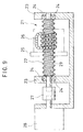
- Fig. 9 shows a prior art mechanism for driving a screw rod by using a motor to rotate a helical rod.
- the mechanism shown in Fig. 9 is constituted of a pair of stands 23, a helical rod 22 rotatably held between the pair of the stands 23 via bearings 24, a nut 25 movable in an axial direction of the helical rod 22 upon rotation of the helical rod 22, and a servo-motor 28 connected with the helical rod 22 via a coupling 27 for rotating the helical rod 22.
- the helical rod 22 is provided with a helical groove 29 formed thereabout along the axial direction thereof, and balls 26 enclosed in the nut 25 are engaged in the groove 29 to hold the nut 25 on the helical rod 22.
- the servo-motor 28 makes the helical rod 22 rotate forward or in reverse so that the nut 25 may be moved in the axial direction of the helical rod.
- a workpiece moved upon movement of the nut 25 is slidably held by rails, a slider or the like (not shown in Fig. 9), so that the load of the workpiece is not moved in a radial direction of the helical rod 22.
- the above-mentioned mechanism for driving a helical rod has the following problems: troubles by back-lash occurs by a minimum space necessary in an engaged portion between the helical rod 22 and balls 26; space-savings may not be achieved because the balls, the nut, the servo-motor, and so on require sufficient space to rotate smoothly; back-lash is increased due to the increase of abrasion between the nut, the balls and the helical rod after a long period of use; and friction between the nut, the balls and the helical rod is increased by minimizing the space between them in order to decrease the back-lash in the mechanism.
- the helical rod is the same shape as a screw rod of the present invention, but the helical rod is used with the balls and the nut. In this point, the helical rod is distinguished from the screw rod of the present invention.
- An object of the invention is to provide a mechanism for driving a screw rod by supersonic vibration and which can resolve the above mentioned problems.
- a mechanism for driving a screw rod by supersonic vibration comprising: a screw rod provided with a groove portion formed helically along an axial direction thereof; a pair of stands for rotatably receiving the screw rod by rotatably holding both ends of the screw rod; a work rack provided to surround the screw rod and which is slidable in the axial direction of the screw rod; at least one first screw rod rotation device secured on one side of the work rack and extending from the work rack to the screw rod.
- the first screw rod rotation device comprises a first vibrator contacting with the groove portion of the screw rod at a specific angle, a first spring urging the first vibrator toward the groove portion of the screw rod at a specific pressure and a first piezoelectric actuator for vibrating the first vibrator upon electrical activation to rotate the screw rod in a first direction; at least one second screw rod rotation device secured on another side of the work rack and extending from the work rack to the screw rod.
- the second screw rod rotation device comprises a second vibrator contacting with the groove portion of the screw rod at a specific angle opposite that for rotation in the first direction, a second spring urging the second vibrator toward the groove portion of the screw rod at a specific pressure and a second piezoelectric actuator for vibrating the second vibrator electrical activation to rotate the screw rod in a second direction.
- the work rack is used for moving a workpiece, but that there are cases in which the workpiece is placed on the work rack directly as well as cases in which the work rack is connected to another rack on which a workpiece is placed.
- the first screw rod rotation device comprising the first vibrator contacting with the groove portion of the screw rod at the specific angle, the first spring urging the first vibrator toward the groove portion of the screw rod at the specific pressure and the first piezoelectric actuator for vibrating the first vibrator upon electrical activation to rotate the screw rod in one direction and the second screw rod rotation device comprising the second vibrator contacting with the groove portion of the screw rod at a specific angle opposite that for rotation in the first direction, the second spring urging the second vibrator to the groove portion of the screw rod at the specific pressure and the second piezoelectric actuator vibrating the second vibrator upon electrical activation to rotate the screw rod in a second direction, are directly mounted on the work rack surrounding the screw rod and slidable in the axial direction of the screw rod to achieve space savings. Back-lash may be prevented by urging the vibrators toward the groove portion with the spring and back-lash due to abrasion by use over a long period of time also may be prevented.
- first and second vibrators are each wedge-shaped and has a front end slant along a circumference of a bottom of the groove of the screw rod.
- the work rack is slidably held on rails extending parallel to an axis of the screw rod.
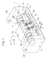
- a mechanism 7 for driving a screw rod by supersonic vibration comprises, as shown in Figs. 1 through 5, a screw rod 2 provided with a groove portion 12 formed helically along an axial direction thereof, a stand 3 for rotatably holding the screw rod 2.
- the stand 3 includes a pair of side walls 3A, 3B for rotatably holding both ends of the screw rod 2, and a bottom plate portion 3C connected between the side walls 3A, 3B.
- a work rack 5 is slidable axially along the screw rod 2, and a plurality of screw rod rotation devices 16 slidably mount the work rack 5 to the screw rod 2.
- the work rack 5 is provided with a pair of side wall portions 5B, 5C located on opposite sides of the screw rod, and a workpiece setting portion 5A bridging between upper ends of the side wall portions 5B, 5C.
- Sliders 10 are provided on lower ends of the work rack 5 so that the work rack 5 is held slidably on a pair of rails 11 laid on the bottom plate portion 3C of the stand 3.
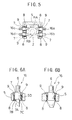
- Each of the screw rod rotation devices 16 is, as shown in Fig. 6, constituted of a vibrator 7, a spring 8, a spring fastening plate 9 and a piezoelectric actuator 6.
- Each vibrator 7 comprises a front end portion 7A formed in a wedge-shape for contacting the groove 12 of the screw rod 2 at a specific angle, a main body 7C slidably inserted into a mounting hole 5D formed in one the side walls 5B, 5C of the work rack 5 and a flange portion 7B formed between the front end portion 7A and the main body 7C and holding one end of the spring 8.
- the spring 8 has one end contacting the flange portion 7B and urges the vibrator 7 into the groove 12 to contact the screw rod 2 at a specific pressure.
- the spring fastening plate 9 secures a part of the main body 7C of the vibrator 7 to a periphery of the mounting hole 5D and holds another end of the spring 8.
- the piezoelectric actuator 6 imparts supersonic vibration to the vibrator 7 upon supply of electric power to the actuator 6.
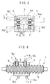
- the screw rod rotation devices 16 include a first screw rod rotation device group 16a, 16a', 16d, 16d' for rotating the screw rod 2 in a direction shown by an arrow RA in Figs. 1 and 3 (hereinafter, the RA rotational direction) and a second screw rod rotation device group 16b, 16b', 16c, 16c' for rotating the screw rod 2 in a direction shown by an arrow RB (hereinafter, the RB rotational direction).
- the vibrator 7 extends in a direction which is at an acute angle to the RA rotational direction and at an obtuse angle to the RB rotational direction (see Fig. 3) and is urged into the groove portion 12 of the screw rod with a pressure determined by the spring 8 in an extending direction thereof.
- the vibrator 7 vibrates so as to produce a large dynamic vector component in the RA rotational direction by supersonic vibrations of the piezoelectric actuator 6, so that the screw rod 2 is rotated in the RA rotational direction.
- the work rack 5 thus moves in a direction shown by an arrow LA in Figs. 1 and 2 (hereinafter, the LA direction) by rotation in the RA rotational direction of the screw rod 2.
- the vibrator 7 extends in a direction which is at an acute angle to the RB rotational direction and at an obtuse angle to the RA rotational direction and is urged into the groove portion 12 of the screw rod with a pressure determined by the spring 8 in an extending direction thereof.
- the vibrator 7 vibrates so as to produce a large dynamic vector component in the RB rotational direction by supersonic vibrations of the piezoelectric actuator 6, so that the screw rod 2 is rotated in the RB rotational direction.
- the work rack 5 thus moves in a direction shown by an arrow LB in Figs. 1 and 2 (hereinafter, the LB direction) by rotation in the RB rotational direction of the screw rod 2.
- a very small current is supplied to the second screw rod rotation device group 16b, 16b', 16c, 16c' to give a very small vibration to the vibrators 7 of the second screw rod rotation device group 16b, 16b', 16c, 16c' when the first screw rod rotation device group 16a, 16a', 16d, 16d' is operated, and that a very small current is supplied to the first screw rod rotation device group 16a, 16a', 16d, 16d' to give a very small vibration to the vibrators 7 of the first screw rod rotation device group 16a, 16a', 16d, 16d' when the second screw rod rotation device group 16b, 16b', 16c, 16c' is operated.
- a dynamic vector component tending to move the screw rod 2 in a reverse direction due to the very small vibrations of the vibrators 7 is much smaller than a dynamic vector component for moving the screw rod 2 due to the normal vibrations of the vibrators 7, the dynamic vector component due to the very small vibrations does not influence the rotation of the vibrator 7 caused by the normal vibrations. Furthermore, the very small vibrations effect a decrease in rotational friction resistance of the screw rod 2, and this effect is larger than the effect of the minor reverse rotation caused by the very small vibrations, and thus the screw rod may be rotated more smoothly.
- every vibrator 7 of the first and the second screw rod rotation device groups 16a - 16d, 16a'- 16d' is pressed into the groove 12 of the screw rod 2 at the specific pressure determined by the spring 8 to hold the work rack 5 at a specific position of the screw rod 2.
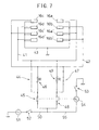
- FIG. 7 One example of an electric circuit diagram for operating the mechanism 1 is shown in Fig. 7.
- a first terminal of each of the piezoelectric actuators 6 in the first screw rod rotation device group 16a, 16a', 16d, 16d' is connected to a first electric power supply line 41
- a first terminal of each of the piezoelectric actuators 6 in the second screw rod rotation device group 16b, 16b', 16c, 16c' is connected to a second electric power supply line 42
- all second terminals of the piezoelectric actuators 6 are connected to a ground line 43.
- a power source line 50 is connected to one terminal of an electric power source 51 via an on/off switch 52 for turning communication to all lines on or off.
- An RA rotation line 44 is connected to the power source line 50 via a b-contact switch 45 of a relay 54.
- the b-contact switch 45 and the first electric power supply line 41 are directly connected to each other, and the b-contact switch 45 and the second electric power supply line 42 are connected to each other via a resistance R with a large value.
- An RB rotation line 47 is connected to the power source line 50 via an a-contact switch 48 of a relay 54.
- the a-contact switch 48 and the second electric power supply line 42 are directly connected to each other, and the a-contact switch 48 and the first electric power supply line 41 are connected to each other via a resistance R with a large value.
- a line 55 for changing a rotational direction is connected between the power source line 50 and the relay 54, and the line 55 is turned on or off by a switch 53 for changing a rotation direction.
- each of the vibrators 7 is formed in a wedge-shape so as to engage in the groove 12 of the screw rod 2, but it is possible for the distal end of each vibrator 7 to be formed in a concave shape so as to engage with a mountain portion between valleys of the groove 12.
- the screw rod rotation devices for rotating the screw rod by the supersonic vibrations are directly mounted on the work rack moved upon rotation of the screw rod, so that space savings may be achieved.
- the vibrators of the screw rod rotation devices are contacted against the screw rod at the specific pressure, so that back-lash of the work rack is prevented, and further, back-lash by frictional wear over a long period of use is also prevented.
- the present invention is such that the screw rod is rotated by supersonic vibrations, so that it is not necessary to supply lubrication oil to the mechanism itself, and therefore, the mechanism is effective for use in the fields of foods, semiconductors, medical instruments and so on, that is to say, fields for which it is undesirable to use lubrication oil.
Abstract
Description
- This invention relates to a mechanism for driving a screw rod to move a work rack in an axial direction of the screw rod by making the screw rod rotate.
- First, Fig. 8 shows a prior art supersonic motor comprising a rotor R and two vibrators S1 and S2. The vibrator S1 is made to vibrate so that the rotor R is pushed by the vibrator S1 to rotate in a clockwise direction in the figure. The vibrator S2 is made to vibrate so that the rotor R is pushed by the vibrator S2 to rotate in a counterclockwise direction in the figure.
- Secondly, Fig. 9 shows a prior art mechanism for driving a screw rod by using a motor to rotate a helical rod.
- The mechanism shown in Fig. 9 is constituted of a pair of
stands 23, ahelical rod 22 rotatably held between the pair of thestands 23 viabearings 24, anut 25 movable in an axial direction of thehelical rod 22 upon rotation of thehelical rod 22, and a servo-motor 28 connected with thehelical rod 22 via acoupling 27 for rotating thehelical rod 22. - The
helical rod 22 is provided with ahelical groove 29 formed thereabout along the axial direction thereof, andballs 26 enclosed in thenut 25 are engaged in thegroove 29 to hold thenut 25 on thehelical rod 22. Thus, the servo-motor 28 makes thehelical rod 22 rotate forward or in reverse so that thenut 25 may be moved in the axial direction of the helical rod. - A workpiece moved upon movement of the
nut 25 is slidably held by rails, a slider or the like (not shown in Fig. 9), so that the load of the workpiece is not moved in a radial direction of thehelical rod 22. - However, the above-mentioned mechanism for driving a helical rod has the following problems: troubles by back-lash occurs by a minimum space necessary in an engaged portion between the
helical rod 22 andballs 26; space-savings may not be achieved because the balls, the nut, the servo-motor, and so on require sufficient space to rotate smoothly; back-lash is increased due to the increase of abrasion between the nut, the balls and the helical rod after a long period of use; and friction between the nut, the balls and the helical rod is increased by minimizing the space between them in order to decrease the back-lash in the mechanism. - Note that the helical rod is the same shape as a screw rod of the present invention, but the helical rod is used with the balls and the nut. In this point, the helical rod is distinguished from the screw rod of the present invention.
- An object of the invention is to provide a mechanism for driving a screw rod by supersonic vibration and which can resolve the above mentioned problems.
- According to one embodiment of the invention, there is provided a mechanism for driving a screw rod by supersonic vibration, comprising: a screw rod provided with a groove portion formed helically along an axial direction thereof; a pair of stands for rotatably receiving the screw rod by rotatably holding both ends of the screw rod; a work rack provided to surround the screw rod and which is slidable in the axial direction of the screw rod; at least one first screw rod rotation device secured on one side of the work rack and extending from the work rack to the screw rod. The first screw rod rotation device comprises a first vibrator contacting with the groove portion of the screw rod at a specific angle, a first spring urging the first vibrator toward the groove portion of the screw rod at a specific pressure and a first piezoelectric actuator for vibrating the first vibrator upon electrical activation to rotate the screw rod in a first direction; at least one second screw rod rotation device secured on another side of the work rack and extending from the work rack to the screw rod. The second screw rod rotation device comprises a second vibrator contacting with the groove portion of the screw rod at a specific angle opposite that for rotation in the first direction, a second spring urging the second vibrator toward the groove portion of the screw rod at a specific pressure and a second piezoelectric actuator for vibrating the second vibrator electrical activation to rotate the screw rod in a second direction. Note that the work rack is used for moving a workpiece, but that there are cases in which the workpiece is placed on the work rack directly as well as cases in which the work rack is connected to another rack on which a workpiece is placed.
- According to this invention, therefore, the first screw rod rotation device comprising the first vibrator contacting with the groove portion of the screw rod at the specific angle, the first spring urging the first vibrator toward the groove portion of the screw rod at the specific pressure and the first piezoelectric actuator for vibrating the first vibrator upon electrical activation to rotate the screw rod in one direction and the second screw rod rotation device comprising the second vibrator contacting with the groove portion of the screw rod at a specific angle opposite that for rotation in the first direction, the second spring urging the second vibrator to the groove portion of the screw rod at the specific pressure and the second piezoelectric actuator vibrating the second vibrator upon electrical activation to rotate the screw rod in a second direction, are directly mounted on the work rack surrounding the screw rod and slidable in the axial direction of the screw rod to achieve space savings. Back-lash may be prevented by urging the vibrators toward the groove portion with the spring and back-lash due to abrasion by use over a long period of time also may be prevented.
- Furthermore, in the present invention, when one of the first and the second piezoelectric actuators is electrically activated, a very small amount of electric current is supplied to the other of the first and the second piezoelectric actuators. Thus, upon rotation of the screw rod, friction of vibrators which do not contribute to the rotation of the screw rod may be decreased.
- Moreover, the first and second vibrators are each wedge-shaped and has a front end slant along a circumference of a bottom of the groove of the screw rod.
- The work rack is slidably held on rails extending parallel to an axis of the screw rod.
- Fig. 1 is an outline perspective view illustrating a mechanism for driving a screw rod by supersonic vibration according to the present invention;
- Fig. 2 is a side elevation view of the mechanism by a supersonic vibration illustrated in Fig. 1;
- Fig. 3 is a cross section view taken along line 3-3 of Fig. 2;
- Fig. 4 is a cross section view taken along line 4-4 of Fig. 3;
- Fig. 5 is a cross section view taken along line 5-5 of Fig. 4;
- Fig. 6A is a side elevation view illustrating a screw rod rotation device, and
- Fig. 6B is a front elevation view of the screw rod rotation device;
- Fig. 7 is an electric circuit diagram showing one example of a driving circuit of the mechanism for driving the screw rod by supersonic vibration;
- Fig. 8 is an illustration for explaining an operating principle of a prior art supersonic motor; and
- Fig. 9 is a cross section view illustrating a prior art mechanism for driving a helical rod by a motor.
-
- Hereinafter, a preferred embodiment of the present invention will be explained with reference to the drawings.
- A
mechanism 7 for driving a screw rod by supersonic vibration according to the preferred embodiment of this invention comprises, as shown in Figs. 1 through 5, ascrew rod 2 provided with agroove portion 12 formed helically along an axial direction thereof, astand 3 for rotatably holding thescrew rod 2. Thestand 3 includes a pair ofside walls screw rod 2, and abottom plate portion 3C connected between theside walls work rack 5 is slidable axially along thescrew rod 2, and a plurality of screwrod rotation devices 16 slidably mount thework rack 5 to thescrew rod 2. - In this embodiment, the
work rack 5 is provided with a pair ofside wall portions workpiece setting portion 5A bridging between upper ends of theside wall portions Sliders 10 are provided on lower ends of thework rack 5 so that thework rack 5 is held slidably on a pair ofrails 11 laid on thebottom plate portion 3C of thestand 3. - Each of the screw
rod rotation devices 16 is, as shown in Fig. 6, constituted of avibrator 7, aspring 8, aspring fastening plate 9 and apiezoelectric actuator 6. Eachvibrator 7 comprises afront end portion 7A formed in a wedge-shape for contacting thegroove 12 of thescrew rod 2 at a specific angle, amain body 7C slidably inserted into amounting hole 5D formed in one theside walls work rack 5 and a flange portion 7B formed between thefront end portion 7A and themain body 7C and holding one end of thespring 8. Thespring 8 has one end contacting the flange portion 7B and urges thevibrator 7 into thegroove 12 to contact thescrew rod 2 at a specific pressure. Thespring fastening plate 9 secures a part of themain body 7C of thevibrator 7 to a periphery of themounting hole 5D and holds another end of thespring 8. Thepiezoelectric actuator 6 imparts supersonic vibration to thevibrator 7 upon supply of electric power to theactuator 6. - Furthermore, the screw
rod rotation devices 16 include a first screw rodrotation device group screw rod 2 in a direction shown by an arrow RA in Figs. 1 and 3 (hereinafter, the RA rotational direction) and a second screw rodrotation device group screw rod 2 in a direction shown by an arrow RB (hereinafter, the RB rotational direction). - In each screw
rod rotation device 16 of the first screw rodrotation device group vibrator 7 extends in a direction which is at an acute angle to the RA rotational direction and at an obtuse angle to the RB rotational direction (see Fig. 3) and is urged into thegroove portion 12 of the screw rod with a pressure determined by thespring 8 in an extending direction thereof. - In this condition, when the
piezoelectric actuator 6 is energized with electricity, thevibrator 7 vibrates so as to produce a large dynamic vector component in the RA rotational direction by supersonic vibrations of thepiezoelectric actuator 6, so that thescrew rod 2 is rotated in the RA rotational direction. Thework rack 5 thus moves in a direction shown by an arrow LA in Figs. 1 and 2 (hereinafter, the LA direction) by rotation in the RA rotational direction of thescrew rod 2. - In the same way, in each screw
rod rotation device 16 of the second screw rodrotation device group vibrator 7 extends in a direction which is at an acute angle to the RB rotational direction and at an obtuse angle to the RA rotational direction and is urged into thegroove portion 12 of the screw rod with a pressure determined by thespring 8 in an extending direction thereof. - In this condition, when the
piezoelectric actuator 6 is energized with electricity, thevibrator 7 vibrates so as to produce a large dynamic vector component in the RB rotational direction by supersonic vibrations of thepiezoelectric actuator 6, so that thescrew rod 2 is rotated in the RB rotational direction. Thework rack 5 thus moves in a direction shown by an arrow LB in Figs. 1 and 2 (hereinafter, the LB direction) by rotation in the RB rotational direction of thescrew rod 2. - Moreover, it is desired that a very small current is supplied to the second screw rod
rotation device group vibrators 7 of the second screw rodrotation device group rotation device group rotation device group vibrators 7 of the first screw rodrotation device group rotation device group - Because a dynamic vector component tending to move the
screw rod 2 in a reverse direction due to the very small vibrations of thevibrators 7 is much smaller than a dynamic vector component for moving thescrew rod 2 due to the normal vibrations of thevibrators 7, the dynamic vector component due to the very small vibrations does not influence the rotation of thevibrator 7 caused by the normal vibrations. Furthermore, the very small vibrations effect a decrease in rotational friction resistance of thescrew rod 2, and this effect is larger than the effect of the minor reverse rotation caused by the very small vibrations, and thus the screw rod may be rotated more smoothly. - Moreover, in the above mentioned mechanism for driving a
screw rod 1, when the electric power is stopped, everyvibrator 7 of the first and the second screw rodrotation device groups 16a - 16d, 16a'- 16d' is pressed into thegroove 12 of thescrew rod 2 at the specific pressure determined by thespring 8 to hold thework rack 5 at a specific position of thescrew rod 2. - One example of an electric circuit diagram for operating the
mechanism 1 is shown in Fig. 7. - In the electric circuit diagram, a first terminal of each of the
piezoelectric actuators 6 in the first screw rodrotation device group power supply line 41, a first terminal of each of thepiezoelectric actuators 6 in the second screw rodrotation device group power supply line 42, and all second terminals of thepiezoelectric actuators 6 are connected to aground line 43. - A
power source line 50 is connected to one terminal of anelectric power source 51 via an on/offswitch 52 for turning communication to all lines on or off. - An
RA rotation line 44 is connected to thepower source line 50 via a b-contact switch 45 of arelay 54. In theRA rotation line 44, the b-contact switch 45 and the first electricpower supply line 41 are directly connected to each other, and the b-contact switch 45 and the second electricpower supply line 42 are connected to each other via a resistance R with a large value. - An
RB rotation line 47 is connected to thepower source line 50 via an a-contactswitch 48 of arelay 54. In theRB rotation line 47, the a-contactswitch 48 and the second electricpower supply line 42 are directly connected to each other, and the a-contactswitch 48 and the first electricpower supply line 41 are connected to each other via a resistance R with a large value. - A
line 55 for changing a rotational direction is connected between thepower source line 50 and therelay 54, and theline 55 is turned on or off by aswitch 53 for changing a rotation direction. - Thus, when the
switch 52 is turned on and theswitch 53 is turned off, a large electric current flows into the first electricpower supply line 41 and a very small electric current limited by the resistance R flows into the second electricpower supply line 42, so that thevibrators 7 of the first screw rodrotation device group vibrators 7 of the second screw rodrotation device group screw rod 2 rotates in the RA rotational direction to move thework rack 5 in the LA direction. - When the
switch 52 and theswitch 53 are turned on, a large electric current flows into the second electricpower supply line 42 and a very small electric current limited by the resistance R flows into the first electricpower supply line 41, so that thevibrators 7 of the second screw rodrotation device group vibrators 7 of the first screw rodrotation device group screw rod 2 rotates in the RB rotational direction to move thework rack 5 in the LB direction. - Note that in the above mentioned embodiment, the distal end of each of the
vibrators 7 is formed in a wedge-shape so as to engage in thegroove 12 of thescrew rod 2, but it is possible for the distal end of eachvibrator 7 to be formed in a concave shape so as to engage with a mountain portion between valleys of thegroove 12. - As mentioned above, according to the invention, the screw rod rotation devices for rotating the screw rod by the supersonic vibrations are directly mounted on the work rack moved upon rotation of the screw rod, so that space savings may be achieved.
- The vibrators of the screw rod rotation devices are contacted against the screw rod at the specific pressure, so that back-lash of the work rack is prevented, and further, back-lash by frictional wear over a long period of use is also prevented.
- Furthermore, the present invention is such that the screw rod is rotated by supersonic vibrations, so that it is not necessary to supply lubrication oil to the mechanism itself, and therefore, the mechanism is effective for use in the fields of foods, semiconductors, medical instruments and so on, that is to say, fields for which it is undesirable to use lubrication oil.
- Although the invention has been described in its preferred form with a certain degree of particularity, it is to be understood that the present disclosure of the preferred form can be changed in the details of construction and different combinations and arrangements of parts may be resorted to without departing from the spirit and the scope of the invention as hereinafter claimed.
Claims (4)
- A mechanism for driving a screw rod by supersonic vibration, comprising: a screw rod (2) provided with a groove portion (12) formed helically along an axial direction thereof; a pair of stands (3A, 3B) rotatably holding opposite ends of said screw rod (2); and a work rack (5) partially surrounding said screw rod (2) and slidable in the axial direction of said screw rod (2), characterized in that:at least one first screw rod rotation device (16a, 16a', 16d, 16d') is secured on one side of said work rack (5) and extending from said work rack (5) to said screw rod, said at least one first screw rod rotation device (16) comprising a first vibrator (7) contacting with said groove portion (12) of said screw rod (2) at a first specific angle, a first spring (8) urging said first vibrator (7) toward said groove portion (12) of said screw rod (29 at a specific pressure and a first piezoelectric actuator (6) for vibrating said first vibrator (7) upon electrical activation to rotate said screw rod (2) in a first rotational direction, andat least one second screw rod rotation device (16b, 16b', 16c, 16c') is secured on another side of said work rack (5) and extending from said work rack (5) to said screw rod (2), said at least one second screw rod rotation device (16) comprising a second vibrator (7) contacting with said groove portion (12) of said screw rod (2) at a second specific angle opposite said first specific angle, a second spring (8) urging said second vibrator (7) toward said groove portion (12) of said screw rod (2) at a specific pressure and a second piezoelectric actuator (6) for vibrating said second vibrator (7) upon electrical activation to rotate said screw rod (2) in a second direction.
- A mechanism for driving a screw rod by supersonic vibration, as claimed in claim 1, wherein:
when one of said first and second piezoelectric actuators (6) is electrically activated, a very small amount of electric current is supplied to the other of said first and second piezoelectric actuators (6). - A mechanism for driving a screw rod by supersonic vibration, as claimed in claim 1 or 2, wherein:
each of said first and second vibrators (7) is wedge-shaped and has a front end (7A) slanted so as to contact a bottom of a valley of said groove portion (12) of said screw rod (2). - A mechanism for driving a screw rod by supersonic vibration, as claimed in claim 1, 2 or 3, further comprising rails (11) extending parallel to said screw rod (2), said rails (11) holding said work rack (5) slidably.
Applications Claiming Priority (2)
| Application Number | Priority Date | Filing Date | Title |
|---|---|---|---|
| JP14065598 | 1998-05-22 | ||
| JP14065598A JP3233901B2 (en) | 1998-05-22 | 1998-05-22 | Screw rod drive mechanism by ultrasonic vibration |
Publications (3)
| Publication Number | Publication Date |
|---|---|
| EP0959268A2 true EP0959268A2 (en) | 1999-11-24 |
| EP0959268A3 EP0959268A3 (en) | 2000-04-05 |
| EP0959268B1 EP0959268B1 (en) | 2001-06-27 |
Family
ID=15273701
Family Applications (1)
| Application Number | Title | Priority Date | Filing Date |
|---|---|---|---|
| EP99302333A Expired - Fee Related EP0959268B1 (en) | 1998-05-22 | 1999-03-25 | A mechanism for driving a screw rod by supersonic vibration |
Country Status (4)
| Country | Link |
|---|---|
| US (1) | US6147435A (en) |
| EP (1) | EP0959268B1 (en) |
| JP (1) | JP3233901B2 (en) |
| DE (1) | DE69900166T2 (en) |
Cited By (4)
| Publication number | Priority date | Publication date | Assignee | Title |
|---|---|---|---|---|
| US6147435A (en) * | 1998-05-22 | 2000-11-14 | Central Gikenkogyo Corporation | Mechanism for driving a screw rod by supersonic vibration |
| CN102843064A (en) * | 2012-09-29 | 2012-12-26 | 哈尔滨工业大学 | Flexible replaceable screw thread pair driving ultrasonic motor |
| CN103671867A (en) * | 2012-09-25 | 2014-03-26 | 舍弗勒技术股份两合公司 | Operating device |
| CN109150001A (en) * | 2018-09-05 | 2019-01-04 | 三英精控(天津)仪器设备有限公司 | A kind of nano positioning and voltage linear actuator and its driving method |
Families Citing this family (12)
| Publication number | Priority date | Publication date | Assignee | Title |
|---|---|---|---|---|
| US6940209B2 (en) | 2003-09-08 | 2005-09-06 | New Scale Technologies | Ultrasonic lead screw motor |
| US7170214B2 (en) * | 2003-09-08 | 2007-01-30 | New Scale Technologies, Inc. | Mechanism comprised of ultrasonic lead screw motor |
| US7309943B2 (en) * | 2003-09-08 | 2007-12-18 | New Scale Technologies, Inc. | Mechanism comprised of ultrasonic lead screw motor |
| US6938905B1 (en) | 2004-11-05 | 2005-09-06 | Haiming Tsai | Hand truck |
| US7922695B2 (en) * | 2007-10-18 | 2011-04-12 | Roche Diagnostics Operations, Inc. | Drug delivery pump drive using linear piezoelectric motor |
| US8172811B2 (en) | 2008-05-15 | 2012-05-08 | Roche Diagnostics Operations, Inc. | Drug delivery pump drive using a shaped memory alloy wire |
| US8450905B2 (en) * | 2009-07-23 | 2013-05-28 | New Scale Technologies | Methods for controlling velocity of at least partially resonant actuators systems and systems thereof |
| US8474778B2 (en) * | 2011-08-29 | 2013-07-02 | Stephen R. Jacobson | Adjustable hands-free mounting apparatus for tablet personal computers |
| US8925407B1 (en) * | 2011-11-30 | 2015-01-06 | Roger Henry Siminoff | Adjustable pressure assembly for a rotating plate in an automotive steering box |
| CN105391337B (en) * | 2015-11-26 | 2017-09-12 | 西安交通大学 | Piezoelectric pile and the big stroke rotary actuator of the high pulling torque of motor combination drive and method |
| DE102017208015B4 (en) | 2017-05-11 | 2024-04-11 | Volkswagen Aktiengesellschaft | Vibration-assisted screwing device with reduced preload force dispersion |
| CN114001134A (en) * | 2021-11-22 | 2022-02-01 | 深圳市伙伴气动精密机械有限公司 | Screw rod electric displacement platform with clamping type nut |
Citations (7)
| Publication number | Priority date | Publication date | Assignee | Title |
|---|---|---|---|---|
| JPS6166574A (en) * | 1984-09-07 | 1986-04-05 | Marcon Electronics Co Ltd | Piezoelectric linear motor |
| EP0231940A2 (en) * | 1986-02-04 | 1987-08-12 | Siemens Aktiengesellschaft | Piezoelectric drive |
| US4728843A (en) * | 1985-11-11 | 1988-03-01 | Taga Electric Co., Ltd. | Ultrasonic vibrator and drive control method thereof |
| US5162692A (en) * | 1986-10-26 | 1992-11-10 | Olympus Optical Company Limited | Ultrasonic oscillator and ultrasonic motor using the same |
| JPH05345247A (en) * | 1992-06-17 | 1993-12-27 | Alps Electric Co Ltd | Direct acting device |
| EP0729193A1 (en) * | 1995-02-27 | 1996-08-28 | New Focus, Inc. | Piezoelectric actuator for optical alignment screws |
| DE19721804A1 (en) * | 1996-07-10 | 1998-01-22 | Univ Magdeburg Tech | Movement conversion or translating device e.g. for precise positioning for small objects |
Family Cites Families (5)
| Publication number | Priority date | Publication date | Assignee | Title |
|---|---|---|---|---|
| US4438364A (en) * | 1981-07-13 | 1984-03-20 | The Garrett Corporation | Piezoelectric actuator |
| JPS60118072A (en) * | 1983-11-30 | 1985-06-25 | Toshiba Corp | Rotary ultrafine moving mechanism |
| JPH0410704Y2 (en) * | 1987-04-20 | 1992-03-17 | ||
| JPH11168258A (en) * | 1997-12-03 | 1999-06-22 | Nippon Telegr & Teleph Corp <Ntt> | Light-amplifying device |
| JP3233901B2 (en) * | 1998-05-22 | 2001-12-04 | セントラル技研工業株式会社 | Screw rod drive mechanism by ultrasonic vibration |
-
1998
- 1998-05-22 JP JP14065598A patent/JP3233901B2/en not_active Expired - Fee Related
-
1999
- 1999-03-15 US US09/267,611 patent/US6147435A/en not_active Expired - Fee Related
- 1999-03-25 EP EP99302333A patent/EP0959268B1/en not_active Expired - Fee Related
- 1999-03-25 DE DE69900166T patent/DE69900166T2/en not_active Expired - Fee Related
Patent Citations (7)
| Publication number | Priority date | Publication date | Assignee | Title |
|---|---|---|---|---|
| JPS6166574A (en) * | 1984-09-07 | 1986-04-05 | Marcon Electronics Co Ltd | Piezoelectric linear motor |
| US4728843A (en) * | 1985-11-11 | 1988-03-01 | Taga Electric Co., Ltd. | Ultrasonic vibrator and drive control method thereof |
| EP0231940A2 (en) * | 1986-02-04 | 1987-08-12 | Siemens Aktiengesellschaft | Piezoelectric drive |
| US5162692A (en) * | 1986-10-26 | 1992-11-10 | Olympus Optical Company Limited | Ultrasonic oscillator and ultrasonic motor using the same |
| JPH05345247A (en) * | 1992-06-17 | 1993-12-27 | Alps Electric Co Ltd | Direct acting device |
| EP0729193A1 (en) * | 1995-02-27 | 1996-08-28 | New Focus, Inc. | Piezoelectric actuator for optical alignment screws |
| DE19721804A1 (en) * | 1996-07-10 | 1998-01-22 | Univ Magdeburg Tech | Movement conversion or translating device e.g. for precise positioning for small objects |
Cited By (5)
| Publication number | Priority date | Publication date | Assignee | Title |
|---|---|---|---|---|
| US6147435A (en) * | 1998-05-22 | 2000-11-14 | Central Gikenkogyo Corporation | Mechanism for driving a screw rod by supersonic vibration |
| CN103671867A (en) * | 2012-09-25 | 2014-03-26 | 舍弗勒技术股份两合公司 | Operating device |
| CN103671867B (en) * | 2012-09-25 | 2017-08-08 | 舍弗勒技术股份两合公司 | Manipulation device |
| CN102843064A (en) * | 2012-09-29 | 2012-12-26 | 哈尔滨工业大学 | Flexible replaceable screw thread pair driving ultrasonic motor |
| CN109150001A (en) * | 2018-09-05 | 2019-01-04 | 三英精控(天津)仪器设备有限公司 | A kind of nano positioning and voltage linear actuator and its driving method |
Also Published As
| Publication number | Publication date |
|---|---|
| EP0959268B1 (en) | 2001-06-27 |
| JP3233901B2 (en) | 2001-12-04 |
| JPH11341839A (en) | 1999-12-10 |
| DE69900166T2 (en) | 2002-01-03 |
| DE69900166D1 (en) | 2001-08-02 |
| EP0959268A3 (en) | 2000-04-05 |
| US6147435A (en) | 2000-11-14 |
Similar Documents
| Publication | Publication Date | Title |
|---|---|---|
| EP0959268B1 (en) | A mechanism for driving a screw rod by supersonic vibration | |
| US6163096A (en) | Electrical drive unit | |
| US6259175B1 (en) | Linear actuator | |
| CA2403562C (en) | Vibratory motor and method of making and using same | |
| EP0557106B1 (en) | Ultrasonic driving motors | |
| US6116104A (en) | Actuator | |
| EP1724906A3 (en) | Electric motor comprising a speed reducing unit and a control circuit board | |
| EP1118741A3 (en) | Rolling contact screw-and-nut transmission device, and linear actuator comprising this device | |
| US5714826A (en) | Electric motor | |
| JP4055691B2 (en) | Industrial robot | |
| US7141897B2 (en) | Electric actuator expanded with sensor and electronic brake | |
| FR2797111A1 (en) | BRUSH PLATE FOR ELECTRIC MOTOR, METHOD FOR MANUFACTURING THIS PLATE AND MODULE FOR MOTOR-FAN GROUP COMPRISING SUCH PLATE | |
| JP3772315B2 (en) | Piezoelectric unit and moving table using the same | |
| CN1149599C (en) | Cam Pawl mechanism of rotary operating electrical components | |
| FR2724764A1 (en) | MULTIFUNCTIONAL ACTUATOR | |
| JP4277569B2 (en) | Linear stage | |
| US7245053B2 (en) | Method to increase actuator torque | |
| SU1238183A1 (en) | Current collecting device | |
| JPH11325213A (en) | Electric actuator | |
| JP3044818B2 (en) | Pulse switch | |
| JP3575248B2 (en) | Drive | |
| JP3758296B2 (en) | Motor equipment | |
| KR200196967Y1 (en) | Circuit breaker | |
| KR100208339B1 (en) | Torque limiting apparatus | |
| JPH08338479A (en) | Thrust force receiver of work gear |
Legal Events
| Date | Code | Title | Description |
|---|---|---|---|
| PUAI | Public reference made under article 153(3) epc to a published international application that has entered the european phase |
Free format text: ORIGINAL CODE: 0009012 |
|
| AK | Designated contracting states |
Kind code of ref document: A2 Designated state(s): DE GB |
|
| AX | Request for extension of the european patent |
Free format text: AL;LT;LV;MK;RO;SI |
|
| PUAL | Search report despatched |
Free format text: ORIGINAL CODE: 0009013 |
|
| RIC1 | Information provided on ipc code assigned before grant |
Free format text: 7F 16H 25/20 A, 7H 02N 2/02 B, 7H 01L 41/09 B |
|
| AK | Designated contracting states |
Kind code of ref document: A3 Designated state(s): AT BE CH CY DE DK ES FI FR GB GR IE IT LI LU MC NL PT SE |
|
| AX | Request for extension of the european patent |
Free format text: AL;LT;LV;MK;RO;SI |
|
| 17P | Request for examination filed |
Effective date: 20000417 |
|
| 17Q | First examination report despatched |
Effective date: 20000726 |
|
| GRAG | Despatch of communication of intention to grant |
Free format text: ORIGINAL CODE: EPIDOS AGRA |
|
| AKX | Designation fees paid |
Free format text: DE GB |
|
| GRAG | Despatch of communication of intention to grant |
Free format text: ORIGINAL CODE: EPIDOS AGRA |
|
| GRAH | Despatch of communication of intention to grant a patent |
Free format text: ORIGINAL CODE: EPIDOS IGRA |
|
| GRAH | Despatch of communication of intention to grant a patent |
Free format text: ORIGINAL CODE: EPIDOS IGRA |
|
| GRAA | (expected) grant |
Free format text: ORIGINAL CODE: 0009210 |
|
| AK | Designated contracting states |
Kind code of ref document: B1 Designated state(s): DE GB |
|
| REF | Corresponds to: |
Ref document number: 69900166 Country of ref document: DE Date of ref document: 20010802 |
|
| REG | Reference to a national code |
Ref country code: GB Ref legal event code: IF02 |
|
| PLBE | No opposition filed within time limit |
Free format text: ORIGINAL CODE: 0009261 |
|
| STAA | Information on the status of an ep patent application or granted ep patent |
Free format text: STATUS: NO OPPOSITION FILED WITHIN TIME LIMIT |
|
| 26N | No opposition filed | ||
| PGFP | Annual fee paid to national office [announced via postgrant information from national office to epo] |
Ref country code: GB Payment date: 20041230 Year of fee payment: 7 |
|
| PGFP | Annual fee paid to national office [announced via postgrant information from national office to epo] |
Ref country code: DE Payment date: 20050524 Year of fee payment: 7 |
|
| PG25 | Lapsed in a contracting state [announced via postgrant information from national office to epo] |
Ref country code: GB Free format text: LAPSE BECAUSE OF NON-PAYMENT OF DUE FEES Effective date: 20060325 |
|
| PG25 | Lapsed in a contracting state [announced via postgrant information from national office to epo] |
Ref country code: DE Free format text: LAPSE BECAUSE OF NON-PAYMENT OF DUE FEES Effective date: 20061003 |
|
| GBPC | Gb: european patent ceased through non-payment of renewal fee |
Effective date: 20060325 |