EP0959153A2 - An electroplating machine - Google Patents
An electroplating machine Download PDFInfo
- Publication number
- EP0959153A2 EP0959153A2 EP98303984A EP98303984A EP0959153A2 EP 0959153 A2 EP0959153 A2 EP 0959153A2 EP 98303984 A EP98303984 A EP 98303984A EP 98303984 A EP98303984 A EP 98303984A EP 0959153 A2 EP0959153 A2 EP 0959153A2
- Authority
- EP
- European Patent Office
- Prior art keywords
- further characterized
- roller
- aperture
- container
- connecting members
- Prior art date
- Legal status (The legal status is an assumption and is not a legal conclusion. Google has not performed a legal analysis and makes no representation as to the accuracy of the status listed.)
- Withdrawn
Links
Images


Classifications
-
- C—CHEMISTRY; METALLURGY
- C25—ELECTROLYTIC OR ELECTROPHORETIC PROCESSES; APPARATUS THEREFOR
- C25D—PROCESSES FOR THE ELECTROLYTIC OR ELECTROPHORETIC PRODUCTION OF COATINGS; ELECTROFORMING; APPARATUS THEREFOR
- C25D5/00—Electroplating characterised by the process; Pretreatment or after-treatment of workpieces
- C25D5/08—Electroplating with moving electrolyte e.g. jet electroplating
-
- B—PERFORMING OPERATIONS; TRANSPORTING
- B01—PHYSICAL OR CHEMICAL PROCESSES OR APPARATUS IN GENERAL
- B01F—MIXING, e.g. DISSOLVING, EMULSIFYING OR DISPERSING
- B01F25/00—Flow mixers; Mixers for falling materials, e.g. solid particles
- B01F25/10—Mixing by creating a vortex flow, e.g. by tangential introduction of flow components
- B01F25/104—Mixing by creating a vortex flow, e.g. by tangential introduction of flow components characterised by the arrangement of the discharge opening
-
- B—PERFORMING OPERATIONS; TRANSPORTING
- B01—PHYSICAL OR CHEMICAL PROCESSES OR APPARATUS IN GENERAL
- B01F—MIXING, e.g. DISSOLVING, EMULSIFYING OR DISPERSING
- B01F35/00—Accessories for mixers; Auxiliary operations or auxiliary devices; Parts or details of general application
- B01F35/75—Discharge mechanisms
- B01F35/753—Discharging at the upper side of the receptacle, e.g. by pressurising the liquid in the receptacle or by centrifugal force
-
- C—CHEMISTRY; METALLURGY
- C25—ELECTROLYTIC OR ELECTROPHORETIC PROCESSES; APPARATUS THEREFOR
- C25D—PROCESSES FOR THE ELECTROLYTIC OR ELECTROPHORETIC PRODUCTION OF COATINGS; ELECTROFORMING; APPARATUS THEREFOR
- C25D17/00—Constructional parts, or assemblies thereof, of cells for electrolytic coating
- C25D17/10—Electrodes, e.g. composition, counter electrode
- C25D17/12—Shape or form
-
- C—CHEMISTRY; METALLURGY
- C25—ELECTROLYTIC OR ELECTROPHORETIC PROCESSES; APPARATUS THEREFOR
- C25D—PROCESSES FOR THE ELECTROLYTIC OR ELECTROPHORETIC PRODUCTION OF COATINGS; ELECTROFORMING; APPARATUS THEREFOR
- C25D17/00—Constructional parts, or assemblies thereof, of cells for electrolytic coating
- C25D17/16—Apparatus for electrolytic coating of small objects in bulk
- C25D17/28—Apparatus for electrolytic coating of small objects in bulk with means for moving the objects individually through the apparatus during treatment
-
- C—CHEMISTRY; METALLURGY
- C25—ELECTROLYTIC OR ELECTROPHORETIC PROCESSES; APPARATUS THEREFOR
- C25D—PROCESSES FOR THE ELECTROLYTIC OR ELECTROPHORETIC PRODUCTION OF COATINGS; ELECTROFORMING; APPARATUS THEREFOR
- C25D21/00—Processes for servicing or operating cells for electrolytic coating
- C25D21/12—Process control or regulation
- C25D21/14—Controlled addition of electrolyte components
-
- H—ELECTRICITY
- H05—ELECTRIC TECHNIQUES NOT OTHERWISE PROVIDED FOR
- H05K—PRINTED CIRCUITS; CASINGS OR CONSTRUCTIONAL DETAILS OF ELECTRIC APPARATUS; MANUFACTURE OF ASSEMBLAGES OF ELECTRICAL COMPONENTS
- H05K3/00—Apparatus or processes for manufacturing printed circuits
- H05K3/22—Secondary treatment of printed circuits
- H05K3/24—Reinforcing the conductive pattern
- H05K3/241—Reinforcing the conductive pattern characterised by the electroplating method; means therefor, e.g. baths or apparatus
Abstract
Description
- This invention relates to an electroplating machine, in particular such a machine for electroplating such substrates as printed circuit boards (PCBs).
- In conventional electroplating machines, the substrates to be plated, e.g. PCBs, are usually positioned vertically, i.e. with their major surfaces facing sideward. The substrates are clamped either at their respective upper edge or lower edge, and lowered into a tank for treatment, or raised therefrom after such treatment. As a complete electroplating process includes a number of steps, including e.g. rinsing, electroplating, washing, etc., the substrates have to be transported from tank to tank. "Horizontal electroplating machines" have therefore been proposed, in which the substrates are positioned horizontally, i.e. with their major surfaces facing upward and downward. The substrates are caused to move relative to the machine from tank to tank along a substantially horizontal path to undergo the whole electroplating process.
- It is an object of the present invention to provide a new horizontal electroplating machine, or at least to provide a useful alternative to the trade. Various other objects of the invention will be apparent from the following discussion.
- According to a first aspect of the present invention, there is provided an apparatus for positioning an electrode for electroplating at least one substrate which moves relative to said apparatus, which apparatus comprising a first end and a second end wherein said first end is positionable nearer than said second end to the path of movement of said substrate relative to said apparatus, wherein said first end comprises a first side which is upstream of the movement of said substrate relative to said apparatus, characterized in that said first side curves towards said second end.
- According to a second aspect of the present invention, there is provided an apparatus for positioning an electrode for electroplating at least one substrate which moves relative to said apparatus, comprising an end positionable near or adjacent to the path of movement of said substrate relative to said apparatus, said end including a first side which is upstream of, and a second side which is downstream of, the movement of said substrate relative to said apparatus, characterized in that said apparatus comprises at least a first member and at least a second member connecting said first and second sides and that said two connecting members are non-parallel to each other.
- According to a third aspect of the present invention, there is provided an apparatus for positioning an electrode for electroplating at least one substrate which moves relative to said apparatus, comprising an end positionable near or adjacent to the path of movement of said substrate relative to said apparatus, said end including a first side which is upstream of, and a second side which is downstream of, the movement of said substrate relative to said apparatus, characterized in that said apparatus comprises at least a first set of plurality of electrically insulating members connecting said first and second sides which are substantially parallel to each other, and that all lines perpendicular to and joining said first and second sides, excluding any part overlapping with one or more of said connecting members, are of substantially the same length.
- According to a fourth aspect of the present invention, there is provided a fluid delivery apparatus comprising a pipe member and a nozzle member, wherein said pipe member comprises an inlet for receiving fluid into said apparatus from an external source, and a plurality of holes allowing passing of said fluid into chamber means of said nozzle member, characterized in that said nozzle member comprises a substantially continuous elongated outlet which is in a fluid-communicable relationship with said chamber means, and through which outlet said fluid is deliverable out of said apparatus.
- According to a fifth aspect of the present invention, there is provided an apparatus for covering a cylindrical object, which apparatus extending over at least substantially the whole length of said object, and including wall means for shielding at least part of the curved outer surface of said object, and a cavity for receiving at least part of said object, characterized in that said cavity is of a depth at least substantially the same as the diameter of said object for accommodating a majority part of said object, whereby said wall means shields a majority part of the curved outer surface of said object.
- According to a sixth aspect of the present invention, there is provided an apparatus for mixing at least one solid chemical with a solution passing therethrough, which apparatus comprising a container with outer wall means, an input end for receiving a solution from an external source into said container, an output end for allowing said solution in said container to depart from said apparatus, and an opening for receiving said chemical into said container, characterized in that said container comprises inner porous wall means defining a cavity to which said solid chemical is receivable, and dividing means positioned between said outer wall means and said inner porous wall means.
- According to a seventh aspect of the present invention, there is provided an apparatus for mixing at least one solid chemical with a solution passing therethrough, which apparatus comprising a container with outer wall means and a longitudinal axis, an input end for receiving said solution from an external source into said container, an output end for allowing said solution to exit said apparatus, and an opening for receiving said chemical into said container, characterized in that said container comprises inner porous wall means defining a cavity to which said solid chemical is receivable, and that there are provided on said porous wall means at least a first aperture means and a second aperture means wherein each of said aperture means comprises at least one aperture, wherein the orientation between the longitudinal axis of the aperture of said first aperture means and a plane containing said respective aperture and said longitudinal axis of said container is different from the orientation between the longitudinal axis of the respective aperture of said second aperture means and a plane containing said respective aperture and said longitudinal axis of said container.
- According to an eighth aspect of the present invention, there is provided an apparatus for allowing the variation of the distance between a first roller and a second roller, wherein each of said first and second rollers comprises an axle about which each respective roller is rotatable, said apparatus comprising a first body member having a first aperture for receiving at least one end of the axle of said first roller and thereby to allow said axle of said first roller to rotate therein, and a second body member comprising a second aperture for receiving at least one end of the axle of said second roller and thereby to allow said axle of said second roller to rotate therein, characterized in that said first roller is translationally movable relative to said second body member in response to entry of an article between said first and second rollers.
- According to a ninth aspect of the present invention, there is provided an electroplating machine comprising one or more apparatus according to one or more of the above aspects of the present invention.
- An embodiment of the present invention will now be described with reference to the accompanying drawings, in which:
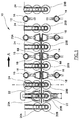
- Fig. 1 is a schematic side view of an electroplating machine according to the present invention;
- Fig. 2A is a bottom view of an electrode positioning apparatus according to the present invention;
- Fig. 2B is an end view of the apparatus shown in Fig. 2A;
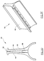
- Fig. 2C is a bottom perspective view of the apparatus shown in Fig. 2A;
- Fig. 3A is a partial sectional side view of a fluid delivery apparatus according to the present invention;
- Fig. 3B is a sectional end view of the apparatus shown in Fig. 3A;
- Fig. 3C is a top view of the apparatus shown in Fig. 3A;
- Fig. 3D is an end view of a nozzle of the fluid delivery apparatus shown in Fig. 3A;
- Fig. 3E is a bottom perspective view of the nozzle of the fluid delivery apparatus shown in Fig. 3D;
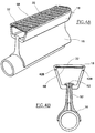
- Fig. 4A is a partial perspective view showing the coupling of the electrode positioning apparatus shown in Fig. 2A and the fluid delivery apparatus shown in Fig. 3A;
- Fig. 4B is a partial sectional end view showing the coupling of the electrode positioning apparatus and the fluid delivery apparatus as shown in Fig. 4A;
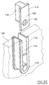
- Fig. 5A is a partial perspective view showing an apparatus for covering a cylindrical object, according to the present invention;
- Fig. 5B is an exploded view of the arrangement shown in Fig. 5A;
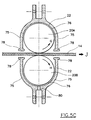
- Fig. 5C is a sectional end view of a farther arrangement of the covering apparatus as shown in Fig. 5A;
- Fig. 6A is a sectional view of a mixing apparatus according to the present invention;
- Fig. 6B is a perspective of the apparatus shown in Fig. 6A;
- Fig. 6C is a top view of a porous pot used in the apparatus shown in Fig. 6A;
- Fig. 6D is a side view of the porous pot shown in Fig. 6C;
- Fig. 6E is a sectional view of the top part of the apparatus shown in Fig. 6A during mixing operation;
- Fig. 6F shows the operation of the upper part of the porous pot shown in Fig. 6C;
- Fig. 6G shows the operation of the lower part of the porous pot shown in Fig. 6C;
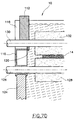
- Fig. 7A shows the front view of an apparatus for allowing the variation of the distance between two rollers;
- Fig. 7B shows the side view of the apparatus shown in Fig. 7A;
- Fig. 7C shows a partial exploded view of the apparatus shown in Fig. 7A as engaged with a wall of another article; and
- Fig. 7D shows the apparatus shown in Fig. 7A as used with two rollers.
-
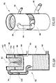
- As shown in Fig. 1, a sectional side view of a portion of an electroplating machine according to the present invention, generally designated as 10, is shown. It should be understood that this figure only illustrates schematically the arrangement of the
machine 10 according to the present invention. Some other component parts are therefore not shown, for clarity purposes. While the part of the portion of themachine 10 to the right of the broken line I-I is atank 12 for containing a liquid, e.g. electrolyte, the part of the portion of themachine 10 to the left of the broken line I-I is outside thetank 12. - A printed circuit board (PCB) 14 (which acts as the cathode in the electroplating process) is shown as disposed horizontally and movable relative to the
machine 10 in the direction shown by the arrow A. Themachine 10 is shown as including a number offluid delivery apparatus 16, some of which being coupled to anelectrode positioning apparatus 18, a number ofupper rollers 20A andlower rollers 20B, in which oneupper roller 20A and onelower roller 20B are covered by a pair of coveringapparatus 22, and a number ofapparatus 24 each allowing the variation of the distance between a respective pair ofrollers - Figs. 2A to 2C show an
electrode positioning apparatus 18 according to the present invention, to which an electrode, e.g. anode, may be mounted in a manner to be discussed below. Thepositioning apparatus 18 is of a roughly trapezoidal shape in cross section, including twoside walls 30 and a bottom side having a number ofribs 32 of equal width joining the twoside walls 30. Theside walls 30 and theribs 32 are formed integrally with each other, and made of, e.g. high capacity polypropylene, an electrically insulating material. - The
PCB 14 is shown in Fig. 2B as approaching thepositioning apparatus 18 in the direction of the arrow B. As thePCB 14 may be very thin, and the liquid in thetank 12 may be moving at a very high speed, the leadingedge 34 of thePCB 14 may flap vigorously, and may thus be jammed by thepositioning apparatus 18. Both theupstream end 36 and thedownstream end 38 of the bottom side of thepositioning apparatus 18 therefore curve toward the oppositeopen side 40 of thepositioning apparatus 18. Such an arrangement significantly reduces the chance of the leadingedge 34 of thePCB 14 being jammed by thepositioning apparatus 18. - The
side walls 30 are provided with two opposite steppedportions 42A and twoopposite slots 42B. All these steppedportions 42A andslots 42B are parallel to each other, and each for receiving a lateral end of an anode plate in a manner to be discussed below. Such an arrangement allows the anode plate to be engaged with thepositioning apparatus 18 and positionable at different distances from its bottom side. Theopen side 40 of thepositioning apparatus 18 is designed for engagement with a fluid delivery apparatus in a manner to be discussed below. - It can be seen clearly in Fig. 2A that the
ribs 32 are arranged into two sets, in which all theribs 32 in the same set are parallel to and equally spaced from each other. It can also be seen that the two sets ofribs 32 subtend an equal angle on opposite sides of a central axis II-II perpendicular to and joiningparallel edges positioning apparatus 18. - The
positioning apparatus 18 is so arranged that theedge 44 is first encounterable by the leadingedge 34 of thePCB 14 when thePCB 14 approaches thepositioning apparatus 18 in the direction of the arrow C. As shown clearly in Fig. 2A, the two sets ofribs 32 slant away from the axis II-II in opposite directions, from theupstream edge 44 to thedownstream edge 46 of thepositioning apparatus 18. As mentioned earlier, the leadingedge 34 of thePCB 14 may flap vigorously, and may thus be jammed by thepositioning apparatus 18. The present arrangement ensures that even if the leadingedge 34 of thePCB 14 so flaps, the two leadingcorners 48 will not be caught by theribs 32, and thus jammed with thepositioning apparatus 18. - Another feature relating to the arrangement of the
ribs 32 is that all the lines joining theedges ribs 32 are spaced from each other. Takeribs rib 32A joins theedge 46, and the mid-point of where thefib 32B joins theedge 44, is perpendicular to both theedges ribs 32. The purpose of such an arrangement is that provided thePCB 14 passes over or under thepositioning apparatus 18 at a relatively constant speed, then, irrespective of the actual speed at which thePCB 14 travels, each point on the surface(s) of thePCB 14 will be exposed to the anode plate mounted in thepositioning apparatus 18 for the same duration of time during the electroplating process. This will ensure that there will be no undesired uneven electroplating of thePCB 14. - Figs. 3A to 3E show various views of the
fluid delivery apparatus 16 shown in Fig. 1. Thefluid delivery apparatus 16 includes two main components, namely anelongate pipe 50 and anelongate nozzle 52, which is of a generally Y-shaped cross-section, engaged with each other, either detachably or fixedly. Thepipe 50 has a circularouter wall 54, provided with a number of holes 56 (of which only two are shown in Fig. 3A) opening to acavity 58 formed between twohalves 60 of thenozzle 52. As shown in Fig. 3C, theholes 56 are arranged along a straight line on theouter wall 54 of thepipe 50. Thenozzle 52 includes an elongate and substantiallycontinuous gap 62, interrupted by a number ofthin partitions 64, of which two are shown in Fig. 3A. Thepartitions 64 are for joining the twohalves 60 together and giving support to thenozzle 52. Thepartitions 64 also divide thecavity 58 of thenozzle 52 into a number of chambers. - During operation, fluid, e.g. an electrolyte for the electroplating process, may enter into the
pipe 50 in the direction shown by the arrow D in Fig. 3A. Because of aclosed end 66 of thepipe 50, the fluid is forced to pass through theholes 56 into thecavity 58 of thenozzle 58. Despite the existence of thepartitions 64, the fluid exits thegap 62 continuously along the whole length of thegap 62. - Figs. 4A and 4B show the coupling of the
fluid delivery apparatus 16 and theanode positioning apparatus 18. It can be seen that thefluid delivery apparatus 16 and theanode positioning apparatus 18 are slidably fitted to each other. In particular, thegap 62 of thenozzle 52 faces, and can thus direct a fluid towards, aporous metal plate 68, which may be made of titanium and acts as an anode in the electroplating process. - While in Figs. 4A and 4B, the
anode plate 68 is positioned very near to theribs 32, theanode plate 68 can also be positioned farther away from theribs 32 by being disposed between theslots 42B. - It is found in practice that the region adjacent to the
anode plate 68 requires a higher rate of replenishment of electrolyte, and spent electrolyte should also be forced away from this region. The present arrangement between thefluid delivery apparatus 16 and theanode positioning apparatus 18 ensures that while fresh electrolyte can be delivered closely to theanode plate 68, spent electrolyte around this region can also be washed away by the jet of fresh electrolyte from thegap 62 of thenozzle 52. - Returning to Fig. 1, it can be seen that the
PCB 14 can pass through a plurality of pairs of oppositely-facinganode positioning apparatus 18, in which theanode plates 68 are positioned close to the path of movement of thePCB 14. The present arrangement provides the following advantages:- - (a) while the
anode plates 68 can be positioned close to the path of movement of thePCB 14, there will be no direct contact between the anode plates and thePCB 14, which would result in undesired shorting of the circuit; - (b) the
anode plates 68 can be positioned at different distances from the path of movement of thePCB 14, and the distance between theanode plates 68 and thePCB 14 can thus be varied; and - (c) easy engagement and disengagement between the
fluid delivery apparatus 16 and theanode positioning apparatus 18. -
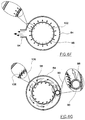
- Figs. 5A to 5C show the use of the
covering apparatus 22 in the area outside of thetank 12. As mentioned earlier, the liquid in thetank 12 may, during operation of themachine 10, be moving at a very high speed. Traces of such liquid may therefore flood or spray out from thetank 12 and land on ametal roller 20A, thus establishing electrical connection, and causing themetal roller 20A to be electroplated undesirably. The coveringapparatus 22 is therefore designed to protect themetal roller 20A from being so electroplated. - Electricity is supplied from an external source (not shown) to the
metal roller 20A viawires 72 and a rotatingcurrent transfer device 74, which also permits theroller 20A to rotate in the direction of the arrow E shown in Fig 5A. A separate rotating current transfer device at the opposite end of theroller 20A also causes theroller 20A to rotate in the same direction. The rotational movement of theroller 20A causes thePCB 14 to move in the direction of the arrow F in Fig. 5A. The electricity supplied from the external source is also transmitted to thePCB 14, thus allowing it to act as the cathode in the electroplating process. The coveringapparatus 22 is elongate in shape and is made of, e.g. poly-vinylchloride, an electrically insulating plastic material. - As shown in Fig. 5C, in addition to the
roller 20A, ametal roller 20B is provided beneath the path of movement of thePCB 14, each of therollers covering apparatus 22. The coveringapparatus 22 has two outer walls 75 (part of which being curved in cross-section along the whole length of the covering apparatus 22) and acavity 76 of a depth roughly the same as the diameter ofrollers walls 75 can shield a majority part of the outer surface of therollers roller 20A rotates in the direction shown by the arrow G, while theroller 20B rotates in the direction shown by the arrow H, in order to move thePCB 14 in the direction shown by the arrow J. It can also be seen that each of thecovering apparatus 22 includes twoleg portions 78, each being thicker than the thickness of thewalls 75. The coveringapparatus 22 positioned below thePCB 14 also includes ahole 80 allowing any stray liquid entering thecavity 76 to be drained out of thecovering apparatus 22. - As discussed earlier, the
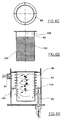
tank 12 of themachine 10 contains electrolyte for use in and during the electroplating process. The concentration of, e.g. copper ions, in the electrolyte will decrease during the process, and ways have been devised to direct used electrolyte (i.e. electrolyte of a low copper ion concentration) away from thetank 12, to increase the concentration of copper ions of such electrolyte, and to pass such replenished electrolyte back into thetank 12. Fig. 6A is a cross-section, and Fig. 6B is a perspective view, of a mixingapparatus 82 used in theelectroplating machine 10, for replenishing used electrolyte. The mixingapparatus 82 has anupper chamber 84 and alower chamber 86. Electrolyte of a low copper ion concentration is pumped viaoutlets 88 of aninput pipe 90 into the lower part of theupper chamber 84. Chemical in solid form, e.g. copper oxide powder, is poured into theupper chamber 84 through atop mouth 92, to be dissolved in the electrolyte. Electrolyte containing a higher concentration of copper ions leaves theupper chamber 84 via anoutput pipe 94 leading from the upper part of theupper chamber 84, enters into thelower chamber 86, and is led, e.g. pumped, away through aduct 96. - Contained within the
upper chamber 84 is aporous pot 98 made of a chemical-resistant material, e.g. poly-vinylchloride. The structure and function of thepot 98 will be discussed below. Positioned between the upper part and lower part of theupper chamber 84, and between acircular wall 100 of theupper chamber 84 and awall 102 of theporous pot 98, is anannular ring 104. - As shown in Figs. 6C and 6D, the
porous pot 98 has a closed bottom and contains thirty-two rows ofholes 106 on itswall 102. The top ten rows ofholes 106 are so oriented that they face directly towards the centrallongitudinal axis 108 of theporous pot 98. As to the lower twenty-two rows ofholes 106, they are oblique to the centrallongitudinal axis 108 of theporous pot 98 by 45°. Theannular ring 104 is situated between the top tenth and eleventh rows ofholes 106, i.e. between the two types ofholes 106. Fig. 6F shows in more detail the orientations ofholes 106 in the top ten rows on thewall 102 of theporous pot 98. The arrows show the directions in which replenished electrolyte leaves the inner cavity of theporous pot 98, and away fromupper chamber 84 through theoutput pipe 94. It can be seen that theholes 106 in the top ten rows are so oriented that they face directly towards the centrallongitudinal axis 108 of theporous pot 98. Put another way, it can be seen that for the top ten rows ofholes 106, the respective longitudinal axis of theholes 106 lies on the plane containing the centrallongitudinal axis 108 of thepot 98 and therespective hole 106, whereas for the lower twenty-two rows ofholes 106, the respective longitudinal axis thereof is oblique to, and thus intersects, a plane containing the centrallongitudinal axis 108 of thepot 98 and therespective hole 106, at 45°. - As shown in Fig. 6G, the electrolyte low in copper ion concentration enters the
upper chamber 84 in a high-speed jet through holes 88 (of which only one is shown here) of theinput pipe 90. It can be seen tat the electrolyte is introduced into the upper chamber at right angle to a plane containing thelongitudinal axis 108 of theporous pot 98 and the vertical part of theinput pipe 90. It can be seen that by way of such an arrangement, the electrolyte will circulate in theupper chamber 84, thus causing a vortex, as shown in Figs. 6A, 6B and 6E. The existence of such a vortex will ensure that the solid chemical, i.e. copper oxide powder in the present example, will stay in the vortex until totally dissolved in the electrolyte. This will enhance the dissolution of the copper oxide powder in the electrolyte, and ensure that no undissolved copper oxide powder can leave theupper chamber 84. - The formation of such a vortex is enhanced by the following additional factors:-
- (A) since the bottom twenty-two rows of
holes 106 are oblique to the centrallongitudinal axis 108 of theporous pot 98 by 45°, the electrolyte can only enter into the inner cavity of theporous pot 98 at such an angle; and - (B) the
annular ring 104 also enhances the formation and maintenance of such a vortex. -
- It should also be noted that the concentration of chemical in the electrolyte leaving the
upper chamber 84 can be adjusted by varying the feed rate of the solid chemical into theupper chamber 84. - It is commonly known that substrates,
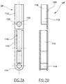
e.g. PCBs 14, to be electroplated may be of various thickness. Electroplating machines should therefore be sufficiently versatile to accommodate substrates of a reasonable range of thickness. Figs. 7A to 7D show anapparatus 24 allowing the variation of the distance between two oppositely facing rollers, in response to the thickness of substrates to be moved therebetween. - The
apparatus 24 is made up of aprimary part 110 and asecondary part 112. Theprimary part 110 is substantially elongate in shape, with acylindrical hole 114 at one end, and anelongate opening 116 at the other end. As to thesecondary part 112, such includes amain body 118 and atongue portion 120, integrally formed with each other. There is also provided ahole 122 on thetongue portion 120. Themain body 118 of thesecondary part 112 is receivable within theopening 116 of theprimary part 110, so as to allow thesecondary part 112 to slide relative to theprimary part 110. Thetongue portion 120 is wider than and extends below the elongate opening 116 (see Fig 7D), so that when theprimary part 110 and thesecondary part 112 are engaged with each other, thetongue portion 120 can cover theelongate opening 116. As can be seen in Fig. 7C, theprimary part 110 may be fixedly secured to awall 124 of a machine, e.g. theelectroplating machine 10. - In use, and as shown in Fig. 7D, an
axle 126 of alower roller 128 is received through thehole 114 of theprimary part 110, and extends through thewall 124 of themachine 10. Theaxle 126 and thehole 114 of theprimary part 110 are sized such that when theaxle 126 is received within thehole 114, the contact area is water-tight, so that the electrolyte cannot escape from themachine 10. It should also be understood that only one side of the relevant part of themachine 10 is shown here, and that there is a similar arrangement on the opposite side of the relevant part of themachine 10. Thelower roller 128 can therefore rotate about itsaxle 126. Similarly, anaxle 130 of anupper roller 132 is received through thehole 122 on thetongue portion 120 and theelongate opening 116 of theprimary part 110. Theupper roller 132 can therefore also rotate about itsaxle 130, and their contact area is also water-tight. It should be noted that the twoaxles axles wall 124 of themachine 10 may be required when therollers tank 12, or to be in electrical contact with an external source of electricity. - When there is no article between the
rollers upper roller 132 is at its lowest position and contacts thelower roller 128. When, however, aPCB 14 moves between therollers upper roller 132 to move vertically upward in order to allow thePCB 14 to pass through. Thesecondary part 112 will consequently move vertically upward relative to the primary part, in response to upward movement of theupper roller 132. This allows theupper roller 132 to continue rotation about itsaxle 130. When thePCB 14 leaves the space between therollers upper roller 132 will fall back to its original lowest position. - By way of such an arrangement, substrates of different thickness can be processed by the
same machine 10, without having to change any of its components. It can also be seen that despite the upward movement of theupper roller 132, thetongue 120 still extends below and seals theelongate opening 116 of theprimary part 110, and prevents the electrolyte from escaping out of themachine 10. - It should be understood that the above only illustrates an example whereby the present invention may be carried out, and that various modifications and alterations may be made thereto without departing from the spirit of the invention.
Claims (73)
- An apparatus for positioning an electrode for electroplating at least one substrate which moves relative to said apparatus, which apparatus comprising a first end and a second end wherein said first end is positionable nearer than said second end to the path of movement of said substrate relative to said apparatus, wherein said first end comprises a first side which is upstream of the movement of said substrate relative to said apparatus, characterized in that said first side curves towards said second end.
- An apparatus according to Claim 1 further characterized in that said first end comprises a second side which is downstream of the movement of said substrate relative to said apparatus, and curves towards said second end.
- An apparatus according to Claim 1 or 2 further characterized in that said apparatus comprises engagement means for positioning said electrode near or adjacent to said first end.
- An apparatus according to Claim 3 further characterized in that said engagement means comprises at least two engagement members, at least one of which on each of two opposite walls of said apparatus.
- An apparatus according to Claim 4 further characterized in that said engagement members are of a substantially equal distance from said first end of said apparatus.
- An apparatus according to Claim 4 or 5 further characterized in that said engagement means comprises at least four engagement members, at least two of which on each one of said two opposite walls of said apparatus, whereby said electrode is positionable at different distances from said first end of said apparatus.
- An apparatus according to any one of Claims 4 to 6 further characterized in that said engagement members are substantially parallel to each other.
- An apparatus according to any one of Claims 4 to 7 further characterized in that at least one of said engagement members comprises a slot.
- An apparatus according to any one of Claim 4 to 8 further characterized in that at least one of said engagement members comprises a step portion.
- An apparatus according to any of the preceding claims further characterized in that said second end comprises a gap for engagement with a fluid delivery apparatus.
- An apparatus according to any of the preceding claims further characterized in that said apparatus is made of high capacity polypropylene.
- An apparatus for positioning an electrode for electroplating at least one substrate which moves relative to said apparatus, comprising an end positionable near or adjacent to the path of movement of said substrate relative to said apparatus, said end including a first side which is upstream of, and a second side which is downstream of, the movement of said substrate relative to said apparatus, characterized in that said apparatus comprises at least a first member and at least a second member connecting said first and second sides and that said two connecting members are non-parallel to each other.
- An apparatus according to Claim 12 further characterized in that said first and second connecting members are positioned to be encounterable by two leading corners of said substrate when said substrate moves towards said apparatus.
- An apparatus according to Claim 12 or 13 further characterized in that said first and second connecting members taper towards each other from said second side towards said first side of said end of the apparatus.
- An apparatus according to any one of Claims 12 to 14 further characterized in that said first and second connecting members subtend a substantially equal angle with and on opposite sides of a line substantially perpendicular to and joining said first and second sides.
- An apparatus according to any one of Claims 12 to 15 further characterized in comprising a plurality of connecting members substantially parallel to said first connecting member.
- An apparatus according to any one of Claims 12 to 16 further characterized in comprising a plurality of connecting members substantially parallel to said second connecting member.
- An apparatus according to any one of Claims 12 to 17 further characterized in that said connecting members are made of an electrically insulating material.
- An apparatus according to Claim 18 further characterized in that said electrically insulating material is high capacity polypropylene.
- An apparatus according to any one of Claims 12 to 19 further characterized in that said apparatus is formed integrally with said connecting members.
- An apparatus for positioning an electrode for electroplating at least one substrate which moves relative to said apparatus, comprising an end positionable near or adjacent to the path of movement of said substrate relative to said apparatus, said end including a first side which is upstream of, and a second side which is downstream of, the movement of said substrate relative to said apparatus, characterized in that said apparatus comprises at least a first set of plurality of electrically insulating members connecting said first and second sides which are substantially parallel to each other, and that all lines perpendicular to and joining said first and second sides, excluding any part overlapping with one or more of said connecting members, are of substantially the same length.
- An apparatus according to Claim 21 further characterized in that said connecting members are substantially parallel to each other.
- An apparatus according to Claim 21 or 22 further characterized in that said connecting members are of substantially the same thickness.
- An apparatus according to any one of Claims 21 to 23 further characterized in that said apparatus comprises a second set of plurality of electrically insulating members connecting said first and second sides, and that all lines perpendicular to and joining said first and second sides, excluding any part overlapping with one or more of said connecting members, are of substantially the same length.
- An apparatus according to Claim 24 further characterized in that said second set of plurality of connecting members are substantially parallel to each other.
- An apparatus according to Claim 24 or 25 further characterized in that said first and second sets of plurality of connecting members are non-parallel to each other.
- An apparatus according to Claim 26 further characterized in that each of said first and second sets of plurality of connecting members subtend a substantially equal angle with and on opposite sides of a line substantially perpendicular to and joining said first and second sides.
- An apparatus according to Claim 27 further characterized in that said first and second sets of plurality of connecting members taper towards each other from said second side towards said first side of said end of the apparatus.
- An apparatus according to any one of Claims 21 to 28 further characterized in that said connecting members are made of a plastic material.
- An apparatus according to Claim 29 further characterized in that said plastic material is high capacity polypropylene.
- An apparatus according to any one of Claims 21 to 30 further characterized in that said apparatus is formed integrally with said connecting members.
- A fluid delivery apparatus comprising a pipe member and a nozzle member, wherein said pipe member comprises an inlet for receiving fluid into said apparatus from an external source, and a plurality of holes allowing passing of said fluid into chamber means of said nozzle member, characterized in that said nozzle member comprises a substantially continuous elongated outlet which is in a fluid-communicable relationship with said chamber means, and through which outlet said fluid is deliverable out of said apparatus.
- An apparatus according to Claim 32 further characterized in that said fluid is deliverable out of said apparatus substantially continuously along substantially the whole length of the elongated outlet of said nozzle member.
- An apparatus according to Claim 32 or 33 further characterized in that said plurality of holes are provided on a wall of said pipe member.
- An apparatus according to any one of Claims 32 to 34 further characterized in that said pipe member is annular in shape.
- An apparatus according to Claim 34 or 35 further characterized in that said plurality of holes are arranged on a substantially straight line on the wall of the pipe member
- An apparatus according to any one of Claims 32 to 36 further characterized in that said chamber means comprises a plurality of chambers.
- An apparatus according to Claim 37 further characterized in that said nozzle member comprises at least one partitioning member for dividing said chamber means into said plurality of chambers.
- An apparatus according to Claim 38 further characterized in comprising a plurality of partitioning members.
- An apparatus according to any one of Claims 32 to 39 further characterized in that said nozzle member is of a substantially Y-shaped cross section.
- An apparatus according to any one of Claims 32 to 40 further characterized in that said pipe member and said nozzle member are detachable to each other.
- An apparatus according to any one of Claims 32 to 40 further characterized in that said pipe member and said nozzle member are fixedly attached to each other.
- An apparatus for covering a cylindrical object, which apparatus extending over at least substantially the whole length of said object, and including wall means for shielding at least part of the curved outer surface of said object, and a cavity for receiving at least part of said object, characterized in that said cavity is of a depth at least substantially the same as the diameter of said object for accommodating a majority part of said object, whereby said wall means shields a majority part of the curved outer surface of said object.
- An apparatus according to Claim 43 further characterized in that said apparatus is elongate in shape.
- An apparatus according to Claim 43 or 44 further characterized in that said apparatus is formed of an insulating material.
- An apparatus according to Claim 45 further characterized in that said insulating material is a plastic material.
- An apparatus according to Claim 46 further characterized in that said plastic material is poly-vinylchloride.
- An apparatus according to any one of Claims 43 to 47 further characterized in that at least part of said wall means is curved along substantially all of its own length.
- An apparatus according to any one of Claims 43 to 48 further characterized in that said wall means comprises at least one hole allowing fluid to be drained from said apparatus.
- An apparatus according to any one of Claims 43 to 49 further characterized in comprising a pair of leg members which are thicker than at least part of the wall means.
- An apparatus for mixing at least one solid chemical with a solution passing therethrough, which apparatus comprising a container with outer wall means, an input end for receiving a solution from an external source into said container, an output end for allowing said solution in said container to depart from said apparatus, and an opening for receiving said chemical into said container, characterized in that said container comprises inner porous wall means defining a cavity to which said solid chemical is receivable, and dividing means positioned between said outer wall means and said inner porous wall means.
- An apparatus according to Claim 51 further characterized in that said output end is provided on said outer wall means.
- An apparatus according to Claim 51 or 52 further characterized in that said output end is above said input means.
- An apparatus for mixing at least one solid chemical with a solution passing therethrough, which apparatus comprising a container with outer wall means and a longitudinal axis, an input end for receiving said solution from an external source into said container, an output end for allowing said solution to exit said apparatus, and an opening for receiving said chemical into said container, characterized in that said container comprises inner porous wall means defining a cavity to which said solid chemical is receivable, and that there are provided on said porous wall means at least a first aperture means and a second aperture means wherein each of said aperture means comprises at least one aperture, wherein the orientation between the longitudinal axis of the aperture of said first aperture means and a plane containing said respective aperture and said longitudinal axis of said container is different from the orientation between the longitudinal axis of the respective aperture of said second aperture means and a plane containing said respective aperture and said longitudinal axis of said container.
- An apparatus according to Claim 54 further characterized in that said first aperture means is positioned above said second aperture means.
- An apparatus according to Claim 54 or 55 further characterized in that said first aperture means comprises a plurality of apertures.
- An apparatus according to any one of Claims 54 to 56 further characterized in that said second aperture means comprises a plurality of apertures.
- An apparatus according to any one of Claims 54 to 57 further characterized in that the longitudinal axis of said respective aperture of said first aperture means lies substantially on a plane containing said respective aperture and said longitudinal axis of said container.
- An apparatus according to any one of Claims 54 to 58 further characterized in that the longitudinal axis of said respective aperture of said second aperture means intersects a plane containing said respective aperture and said longitudinal axis of said container.
- An apparatus according to any one of Claims 54 to 59 further characterized in tat the longitudinal axis of said respective aperture of said second aperture means intersects a plane containing said respective aperture and said longitudinal axis of said container at substantially 45°.
- An apparatus according to any one of Claims 54 to 60 further characterized in that said solution is delivered into said container at an angle to the plane containing said longitudinal axis of said container and said input end, and thereby to cause said solution to rotate in said container.
- An apparatus according to Claim 61 further characterized in that said angle is substantially 90°.
- An apparatus according to any one of Claims 54 to 62 further characterized in that said solution enters into said cavity via said second aperture means.
- An apparatus according to any one of Claims 54 to 63 further characterized in that said solution exits said cavity via said first aperture means.
- An apparatus for allowing the variation of the distance between a first roller and a second roller, wherein each of said first and second rollers comprises an axle about which each respective roller is rotatable, said apparatus comprising a first body member having a first aperture for receiving at least one end of the axle of said first roller and thereby to allow said axle of said first roller to rotate therein, and a second body member comprising a second aperture for receiving at least one end of the axle of said second roller and thereby to allow said axle of said second roller to rotate therein, characterized in that said first roller is translationally movable relative to said second body member in response to entry of an article between said first and second rollers.
- An apparatus according to Claim 65 further characterized in that said first roller is positioned above said second roller
- An apparatus according to Claim 65 or 66 further characterized in that the axle of said first roller is substantially parallel to the axle of said second roller.
- An apparatus according to Claim 67 further characterized in that the axle of said first roller and the axle of said second roller lie substantially on a common vertical plane.
- An apparatus according to any one of Claims 65 to 68 further characterized in that said first roller is movable translationally relative to said first body member substantially vertically.
- An apparatus according to any one of Claims 65 to 69 further characterized in that said first body member is slidably movable relative to said second body member.
- An apparatus according to any one of Claims 65 to 70 further characterized in that said first body member is releasably engageable with said second body member.
- An apparatus according to any one of Claims 65 to 71 further characterized in that said first and second rollers contact each other in the absence of any article therebetween.
- An electroplating machine comprising an apparatus according to any of the preceding claims.
Priority Applications (9)
| Application Number | Priority Date | Filing Date | Title |
|---|---|---|---|
| DE05075545T DE05075545T1 (en) | 1998-05-20 | 1998-05-20 | Apparatus for electroplating |
| EP05075545A EP1541719A3 (en) | 1998-05-20 | 1998-05-20 | An electroplating machine |
| DE05075546T DE05075546T1 (en) | 1998-05-20 | 1998-05-20 | Apparatus for electroplating |
| EP98303984A EP0959153A3 (en) | 1998-05-20 | 1998-05-20 | An electroplating machine |
| EP05075546A EP1541720A3 (en) | 1998-05-20 | 1998-05-20 | An electroplating machine |
| US09/143,045 US6174417B1 (en) | 1998-05-20 | 1998-08-28 | Electroplating machine |
| CNB981193552A CN1148471C (en) | 1998-05-20 | 1998-09-21 | Electroplating machine |
| US09/436,086 US6241860B1 (en) | 1998-05-20 | 1999-11-08 | Electroplating machine |
| US09/436,061 US6251234B1 (en) | 1998-05-20 | 1999-11-08 | Electroplating machine |
Applications Claiming Priority (1)
| Application Number | Priority Date | Filing Date | Title |
|---|---|---|---|
| EP98303984A EP0959153A3 (en) | 1998-05-20 | 1998-05-20 | An electroplating machine |
Related Child Applications (2)
| Application Number | Title | Priority Date | Filing Date |
|---|---|---|---|
| EP05075545A Division EP1541719A3 (en) | 1998-05-20 | 1998-05-20 | An electroplating machine |
| EP05075546A Division EP1541720A3 (en) | 1998-05-20 | 1998-05-20 | An electroplating machine |
Publications (2)
| Publication Number | Publication Date |
|---|---|
| EP0959153A2 true EP0959153A2 (en) | 1999-11-24 |
| EP0959153A3 EP0959153A3 (en) | 2000-09-13 |
Family
ID=8234838
Family Applications (3)
| Application Number | Title | Priority Date | Filing Date |
|---|---|---|---|
| EP98303984A Withdrawn EP0959153A3 (en) | 1998-05-20 | 1998-05-20 | An electroplating machine |
| EP05075546A Withdrawn EP1541720A3 (en) | 1998-05-20 | 1998-05-20 | An electroplating machine |
| EP05075545A Withdrawn EP1541719A3 (en) | 1998-05-20 | 1998-05-20 | An electroplating machine |
Family Applications After (2)
| Application Number | Title | Priority Date | Filing Date |
|---|---|---|---|
| EP05075546A Withdrawn EP1541720A3 (en) | 1998-05-20 | 1998-05-20 | An electroplating machine |
| EP05075545A Withdrawn EP1541719A3 (en) | 1998-05-20 | 1998-05-20 | An electroplating machine |
Country Status (4)
| Country | Link |
|---|---|
| US (3) | US6174417B1 (en) |
| EP (3) | EP0959153A3 (en) |
| CN (1) | CN1148471C (en) |
| DE (1) | DE05075545T1 (en) |
Cited By (9)
| Publication number | Priority date | Publication date | Assignee | Title |
|---|---|---|---|---|
| DE10043815A1 (en) * | 2000-09-06 | 2002-04-04 | Egon Huebel | Contacting planar goods, e.g. PCBs and printed circuit films for diverse electrolytic treatments, connects goods without relative motion for duration of treatment |
| DE10043814C1 (en) * | 2000-09-06 | 2002-04-11 | Egon Huebel | Continuous electrochemical treatment of circuit boards or other goods, comprises placing electrically-insulating, ion-permeable material between electrodes and objects |
| DE10065643C2 (en) * | 2000-12-29 | 2003-03-20 | Egon Huebel | Device and method for the electrochemical treatment of strip-like and plate-like material |
| WO2003064733A1 (en) * | 2002-01-28 | 2003-08-07 | Huebel Egon | Method and device for electrically contacting a product to be treated in electrolytic systems |
| DE10019713C2 (en) * | 2000-04-20 | 2003-11-13 | Atotech Deutschland Gmbh | Device and method for electrical contacting of goods to be treated electrolytically in continuous systems |
| WO2005059206A2 (en) * | 2003-12-19 | 2005-06-30 | Atotech Deutschland Gmbh | Treatment unit for the wet-chemical or electrolytic treatment of flat workpieces |
| DE102005031948B3 (en) * | 2005-07-08 | 2006-06-14 | Höllmüller Maschinenbau GmbH | Device for electrolytically treating strip-like material comprises contact rollers made from metal arranged on at least one side of the material and counter rollers arranged on the opposite-lying side of the strip as a contact pair |
| WO2007009448A1 (en) * | 2005-07-20 | 2007-01-25 | Haendlmeier Viktoria | System for electrodepositing a conductive layer on a nonconductive carrier material |
| US7473344B2 (en) | 2001-08-22 | 2009-01-06 | Atotech Deutschland Gmbh | Segmented counterelectrode for an electrolytic treatment system |
Families Citing this family (8)
| Publication number | Priority date | Publication date | Assignee | Title |
|---|---|---|---|---|
| US7144488B2 (en) * | 2002-06-05 | 2006-12-05 | Shipley Company, L.L.C. | Electrode, electrochemical cell, and method for analysis of electroplating baths |
| US7204918B2 (en) * | 2003-03-10 | 2007-04-17 | Modular Components National, Inc. | High efficiency plating apparatus and method |
| JP4992428B2 (en) * | 2004-09-24 | 2012-08-08 | イビデン株式会社 | Plating method and plating apparatus |
| TW200741037A (en) * | 2006-01-30 | 2007-11-01 | Ibiden Co Ltd | Plating apparatus and plating method |
| TW200829726A (en) * | 2006-11-28 | 2008-07-16 | Basf Ag | Method and device for electrolytic coating |
| US8262894B2 (en) * | 2009-04-30 | 2012-09-11 | Moses Lake Industries, Inc. | High speed copper plating bath |
| CN110392486A (en) * | 2019-07-24 | 2019-10-29 | 苏州创峰光电科技有限公司 | Convey axle sleeve and circuit board wet process equipment |
| CN110791786B (en) * | 2019-11-22 | 2020-11-17 | 深圳市金辉展电子有限公司 | Electroplating solution adding and spraying device for electroplating PCB |
Citations (7)
| Publication number | Priority date | Publication date | Assignee | Title |
|---|---|---|---|---|
| US4607590A (en) * | 1982-09-07 | 1986-08-26 | Pender Don P | Apparatus for directing fluid stream against substrate sheet |
| US4800001A (en) * | 1986-02-07 | 1989-01-24 | Robert Bosch Gmbh | Method and apparatus for continuously galvanizing flat workpieces, and especially printed circuit boards |
| EP0310401A1 (en) * | 1987-10-01 | 1989-04-05 | Furukawa Circuit Foil Co., Ltd. | Insoluble electrode device |
| EP0444359A2 (en) * | 1990-02-26 | 1991-09-04 | Advanced Systems Incorporated | Dynamic flood conveyor with weir |
| EP0460804A1 (en) * | 1990-06-06 | 1991-12-11 | United Kingdom Atomic Energy Authority | A method of mixing a liquid and solids and apparatus therefor |
| EP0522573A1 (en) * | 1991-07-11 | 1993-01-13 | Nordson Corporation | Slot nozzle for applying fluids |
| DE4324330A1 (en) * | 1992-08-01 | 1994-02-03 | Atotech Deutschland Gmbh | Process for the electrolytic treatment of, in particular, flat items to be treated, and arrangement, in particular for carrying out the process |
Family Cites Families (73)
| Publication number | Priority date | Publication date | Assignee | Title |
|---|---|---|---|---|
| US1536569A (en) * | 1923-08-07 | 1925-05-05 | Cruse Henry | Impregnation of fibers by electrolysis |
| NL68330C (en) * | 1950-11-03 | |||
| US3804060A (en) * | 1970-03-27 | 1974-04-16 | Sperry Rand Corp | Liquid epitaxy apparatus |
| US3772193A (en) * | 1971-11-08 | 1973-11-13 | First National City Bank | Device and method for introducing a chemical into a liquid |
| US3975242A (en) | 1972-11-28 | 1976-08-17 | Nippon Steel Corporation | Horizontal rectilinear type metal-electroplating method |
| CA1025794A (en) | 1972-11-29 | 1978-02-07 | Kiyotoshi Iwasaki | Horizontal, rectilinear type metal-electroplating method and apparatus for carrying out the same |
| AU473480B2 (en) | 1972-12-12 | 1976-06-24 | Nippon Steel Corporation | Horizontal, rectilinear type metal-electroplating method and apparatus for carrying out thesame |
| JPS5243733A (en) | 1975-10-03 | 1977-04-06 | Nippon Kokan Kk | Method of forming jet stream of plating solution in horizontal type electroplating and apparatus for said method |
| JPS5636933Y2 (en) | 1976-03-31 | 1981-08-31 | ||
| JPS5333745A (en) | 1976-09-09 | 1978-03-29 | Gunpoo Kk | Device for braking advance of cloth in sewing machine |
| JPS5337545A (en) | 1976-09-20 | 1978-04-06 | Kobe Steel Ltd | Method of controlling level of plating solution in continuous horizontal type electroplating line |
| JPS5524141Y2 (en) | 1976-10-16 | 1980-06-09 | ||
| JPS53125942A (en) | 1977-04-12 | 1978-11-02 | Sumitomo Metal Ind Ltd | Horizontal multi-tank type continuous single side electroplating apparatus |
| GB1529188A (en) | 1977-09-05 | 1978-10-18 | Eidschun C | Continuous contact plater and electroplating method |
| CA1144522A (en) | 1977-09-09 | 1983-04-12 | Charles D. Eidschun | Continuous contact plater |
| CA1132085A (en) | 1977-09-09 | 1982-09-21 | Charles D. Eidschun | Continuous contact plater and method |
| US4260468A (en) * | 1979-09-10 | 1981-04-07 | Bradley James A | Gas induction swimming pool chlorinator |
| US4237641A (en) * | 1979-10-10 | 1980-12-09 | Gupton Jimmie R | Cleaning and coating fishing line |
| DE3001726C2 (en) | 1980-01-18 | 1984-08-09 | Gebr. Schmid GmbH & Co, 7290 Freudenstadt | Device for treating a printed circuit board |
| JPS57101692A (en) | 1980-12-16 | 1982-06-24 | Nippon Steel Corp | Horizontal electroplating method by insoluble electrode |
| JPS57120690A (en) | 1981-01-21 | 1982-07-27 | Nippon Kokan Kk <Nkk> | Method for prevention of inclusion of foreign matter to outlet side sealing rolls in horizontal type electroplating device |
| US4385967A (en) | 1981-10-07 | 1983-05-31 | Chemcut Corporation | Electroplating apparatus and method |
| US4459183A (en) | 1981-10-07 | 1984-07-10 | Chemcut Corporation | Electroplating apparatus and method |
| JPS5871396A (en) | 1981-10-23 | 1983-04-28 | Nippon Kokan Kk <Nkk> | Anode-electric conductor structure in horizontal electroplating apparatus |
| US4419233A (en) * | 1981-11-18 | 1983-12-06 | Baker Marvin E | Chlorinator for a swimming pool |
| JPS5893897A (en) | 1981-11-30 | 1983-06-03 | Kawasaki Steel Corp | Exchanging method for lower electrode in horizontal type electroplating cell for steel plate |
| JPS6028920B2 (en) | 1981-12-21 | 1985-07-08 | 日本鋼管株式会社 | Horizontal electroplating equipment |
| JPS58161792A (en) | 1982-03-20 | 1983-09-26 | Nippon Steel Corp | Horizontal electroplating method with alloy |
| JPS59116398A (en) | 1982-12-24 | 1984-07-05 | Kawasaki Steel Corp | Horizontal type electroplating cell |
| JPS61186498A (en) | 1985-02-13 | 1986-08-20 | Nippon Kokan Kk <Nkk> | Operating method of plating in horizontal type electroplating installation |
| CN85106153A (en) | 1985-08-15 | 1987-03-04 | 汉斯·荷尔米勒机器制造有限公司 | Method at etching printed circuit plate |
| JPS62136596A (en) * | 1985-12-09 | 1987-06-19 | Fuji Photo Film Co Ltd | Continuous electrolytic treatment device for metallic web |
| JPS62192600A (en) | 1986-02-17 | 1987-08-24 | Nippon Kokan Kk <Nkk> | Electrode for horizontal type electroplating |
| US4724856A (en) | 1986-03-17 | 1988-02-16 | Pender Don P | Dynamic flood conveyor |
| US4738879A (en) * | 1986-07-02 | 1988-04-19 | Xerox Corporation | Coating system |
| DE3624481A1 (en) | 1986-07-19 | 1988-01-28 | Schering Ag | ARRANGEMENT FOR THE ELECTROLYTIC TREATMENT OF PLATE-SHAPED OBJECTS |
| US4755271A (en) | 1986-07-28 | 1988-07-05 | Siemens Aktiengesellschaft | Electroplating apparatus for plate-shaped workpieces, particularly printed circuit boards |
| US4761213A (en) | 1986-07-28 | 1988-08-02 | Siemens Aktiengesellschaft | Treatment facility particularly for printed circuit boards to be treated while in a horizontal plane |
| JPS63111196A (en) | 1986-10-28 | 1988-05-16 | Kawasaki Steel Corp | Horizontal continuous electroplating method for steel sheet |
| EP0276725B1 (en) | 1987-01-26 | 1991-09-04 | Siemens Aktiengesellschaft | Apparatus for electroplating plate-like work pieces, particularly circuit boards |
| DE3703542A1 (en) | 1987-02-06 | 1988-08-18 | Schering Ag | METHOD AND ARRANGEMENT FOR LOADING CARRYING RACKS IN PLANTS FOR CHEMICAL TREATMENT IN BATHS, IN PARTICULAR FOR GALVANIZING PLATE-SHAPED OBJECTS |
| DE8703114U1 (en) | 1987-02-25 | 1987-04-09 | Schering Ag, 1000 Berlin Und 4709 Bergkamen, De | |
| US4986888A (en) | 1988-07-07 | 1991-01-22 | Siemens Aktiengesellschaft | Electroplating apparatus for plate-shaped workpieces |
| EP0351569B1 (en) | 1988-07-07 | 1993-08-25 | Siemens Nixdorf Informationssysteme Aktiengesellschaft | Apparatus for electroplating platelike articles, particularly circuit boards |
| EP0361029B1 (en) | 1988-09-01 | 1993-05-19 | Siemens Nixdorf Informationssysteme Aktiengesellschaft | Electroplating apparatus for planar work pieces, particularly circuit boards |
| DE58904414D1 (en) | 1988-09-01 | 1993-06-24 | Siemens Nixdorf Inf Syst | GALVANIZING DEVICE FOR PANEL-SHAPED WORKPIECES, ESPECIALLY PCB. |
| US4871435A (en) | 1988-10-14 | 1989-10-03 | Charles Denofrio | Electroplating apparatus |
| JPH0670279B2 (en) | 1989-03-02 | 1994-09-07 | 日本鋼管株式会社 | Horizontal electric plating device |
| DE3939681A1 (en) | 1989-12-01 | 1991-06-06 | Schering Ag | METHOD FOR CONTROLLING THE OUTLET OF GALVANIC PLANTS AND FOR IMPLEMENTING THE METHOD OF THE SERVICE ARRANGEMENT |
| JP2801710B2 (en) | 1989-12-20 | 1998-09-21 | 川崎製鉄株式会社 | Horizontal electroplating equipment |
| JPH03236495A (en) | 1990-02-14 | 1991-10-22 | Kawasaki Steel Corp | Horizontal type electroplating device |
| US4985111A (en) | 1990-03-02 | 1991-01-15 | Chemcut Corporation | Process and apparatus for intermittent fluid application |
| JP2529893B2 (en) | 1990-05-22 | 1996-09-04 | 日本鋼管株式会社 | Horizontal electric plating device |
| JPH0474896A (en) | 1990-07-18 | 1992-03-10 | Nkk Corp | Horizontal electroplating device |
| JPH086198B2 (en) | 1990-08-15 | 1996-01-24 | 株式会社アルメックス | Horizontal transfer type plating equipment |
| US5098542A (en) * | 1990-09-11 | 1992-03-24 | Baker Hughes Incorporated | Controlled plating apparatus and method for irregularly-shaped objects |
| JP2747382B2 (en) | 1991-07-03 | 1998-05-06 | 義秀 萩原 | Green juice or its dry powder |
| US5211826A (en) | 1991-09-26 | 1993-05-18 | Siemens Aktiengesellschaft | Electroplating means for perforated printed circuit boards to be treated in a horizontal pass |
| DE4212567A1 (en) * | 1992-03-14 | 1993-09-16 | Schmid Gmbh & Co Geb | DEVICE FOR TREATING OBJECTS, IN PARTICULAR GALVANIZING DEVICES FOR PCBS |
| JP2816092B2 (en) | 1994-03-31 | 1998-10-27 | 川崎製鉄株式会社 | Horizontal electroplating equipment |
| US5427748A (en) * | 1994-04-21 | 1995-06-27 | Ppg Industries, Inc. | Chemical feeder |
| JPH0892783A (en) | 1994-09-27 | 1996-04-09 | Kawasaki Steel Corp | Horizontal type electroplating device |
| DE19509313A1 (en) | 1995-03-15 | 1996-09-19 | Schmid Gmbh & Co Geb | Method and device for treating plate-shaped objects, in particular printed circuit boards |
| US5553700A (en) | 1995-04-10 | 1996-09-10 | Atotech Usa, Inc. | Treatment method and apparatus for printed circuit boards and the like |
| CN2232047Y (en) | 1995-05-26 | 1996-07-31 | 深圳宝峰电器有限公司 | Metal surface plate horizontal moving type electroplating machine |
| US5741361A (en) * | 1995-07-06 | 1998-04-21 | Allan H. McKinnon | Method for fluid transport |
| US5693141A (en) * | 1995-07-21 | 1997-12-02 | Tramont; Thomas J. | Special effect paint roller |
| US5658441A (en) * | 1995-12-18 | 1997-08-19 | Cfc, Inc. | Conveyorized spray plating machine |
| US5643425A (en) * | 1996-03-14 | 1997-07-01 | Hoshizaki Denki Kabushiki Kaisha | Saturated brine tank in apparatus for production of electrolyzed water |
| DE19628784A1 (en) * | 1996-07-17 | 1998-01-22 | Schmid Gmbh & Co Geb | Device for treating objects, in particular electroplating device for printed circuit boards |
| CN1174249A (en) | 1996-08-16 | 1998-02-25 | 柯建信 | Jet electroplating method |
| CN1174251A (en) | 1996-08-16 | 1998-02-25 | 柯建信 | Separated secondary electroplating method |
| CN1056423C (en) | 1996-08-16 | 2000-09-13 | 柯建信 | Immersing spray method |
-
1998
- 1998-05-20 DE DE05075545T patent/DE05075545T1/en active Pending
- 1998-05-20 EP EP98303984A patent/EP0959153A3/en not_active Withdrawn
- 1998-05-20 EP EP05075546A patent/EP1541720A3/en not_active Withdrawn
- 1998-05-20 EP EP05075545A patent/EP1541719A3/en not_active Withdrawn
- 1998-08-28 US US09/143,045 patent/US6174417B1/en not_active Expired - Fee Related
- 1998-09-21 CN CNB981193552A patent/CN1148471C/en not_active Expired - Fee Related
-
1999
- 1999-11-08 US US09/436,061 patent/US6251234B1/en not_active Expired - Fee Related
- 1999-11-08 US US09/436,086 patent/US6241860B1/en not_active Expired - Fee Related
Patent Citations (7)
| Publication number | Priority date | Publication date | Assignee | Title |
|---|---|---|---|---|
| US4607590A (en) * | 1982-09-07 | 1986-08-26 | Pender Don P | Apparatus for directing fluid stream against substrate sheet |
| US4800001A (en) * | 1986-02-07 | 1989-01-24 | Robert Bosch Gmbh | Method and apparatus for continuously galvanizing flat workpieces, and especially printed circuit boards |
| EP0310401A1 (en) * | 1987-10-01 | 1989-04-05 | Furukawa Circuit Foil Co., Ltd. | Insoluble electrode device |
| EP0444359A2 (en) * | 1990-02-26 | 1991-09-04 | Advanced Systems Incorporated | Dynamic flood conveyor with weir |
| EP0460804A1 (en) * | 1990-06-06 | 1991-12-11 | United Kingdom Atomic Energy Authority | A method of mixing a liquid and solids and apparatus therefor |
| EP0522573A1 (en) * | 1991-07-11 | 1993-01-13 | Nordson Corporation | Slot nozzle for applying fluids |
| DE4324330A1 (en) * | 1992-08-01 | 1994-02-03 | Atotech Deutschland Gmbh | Process for the electrolytic treatment of, in particular, flat items to be treated, and arrangement, in particular for carrying out the process |
Cited By (16)
| Publication number | Priority date | Publication date | Assignee | Title |
|---|---|---|---|---|
| US7033468B2 (en) | 2000-04-20 | 2006-04-25 | Atotech Deutschland Gmbh | Elastic contact element |
| DE10019713C2 (en) * | 2000-04-20 | 2003-11-13 | Atotech Deutschland Gmbh | Device and method for electrical contacting of goods to be treated electrolytically in continuous systems |
| DE10043814C1 (en) * | 2000-09-06 | 2002-04-11 | Egon Huebel | Continuous electrochemical treatment of circuit boards or other goods, comprises placing electrically-insulating, ion-permeable material between electrodes and objects |
| DE10043815C2 (en) * | 2000-09-06 | 2002-08-08 | Egon Huebel | Method and device for electrical contacting of material to be treated in electrolytic systems |
| DE10043815A1 (en) * | 2000-09-06 | 2002-04-04 | Egon Huebel | Contacting planar goods, e.g. PCBs and printed circuit films for diverse electrolytic treatments, connects goods without relative motion for duration of treatment |
| DE10065643C2 (en) * | 2000-12-29 | 2003-03-20 | Egon Huebel | Device and method for the electrochemical treatment of strip-like and plate-like material |
| US7473344B2 (en) | 2001-08-22 | 2009-01-06 | Atotech Deutschland Gmbh | Segmented counterelectrode for an electrolytic treatment system |
| WO2003064733A1 (en) * | 2002-01-28 | 2003-08-07 | Huebel Egon | Method and device for electrically contacting a product to be treated in electrolytic systems |
| WO2005059206A3 (en) * | 2003-12-19 | 2006-01-12 | Atotech Deutschland Gmbh | Treatment unit for the wet-chemical or electrolytic treatment of flat workpieces |
| JP2007514866A (en) * | 2003-12-19 | 2007-06-07 | アトーテヒ ドイッチュラント ゲゼルシャフト ミット ベシュレンクテル ハフツング | Processing unit for wet chemical or electrolytic treatment of flat workpieces |
| WO2005059206A2 (en) * | 2003-12-19 | 2005-06-30 | Atotech Deutschland Gmbh | Treatment unit for the wet-chemical or electrolytic treatment of flat workpieces |
| US7993486B2 (en) | 2003-12-19 | 2011-08-09 | Atotech Deutschland Gmbh | Treatment unit for the wet-chemical or electrolytic treatment of flat workpieces |
| JP4887157B2 (en) * | 2003-12-19 | 2012-02-29 | アトーテヒ ドイッチュラント ゲゼルシャフト ミット ベシュレンクテル ハフツング | Processing unit for wet chemical or electrolytic treatment of flat workpieces |
| DE102005031948B3 (en) * | 2005-07-08 | 2006-06-14 | Höllmüller Maschinenbau GmbH | Device for electrolytically treating strip-like material comprises contact rollers made from metal arranged on at least one side of the material and counter rollers arranged on the opposite-lying side of the strip as a contact pair |
| EP1741806A1 (en) | 2005-07-08 | 2007-01-10 | Höllmüller Maschinenbau GmbH | Apparatus and process for electroplating treatment of foils from roller to roller |
| WO2007009448A1 (en) * | 2005-07-20 | 2007-01-25 | Haendlmeier Viktoria | System for electrodepositing a conductive layer on a nonconductive carrier material |
Also Published As
| Publication number | Publication date |
|---|---|
| EP0959153A3 (en) | 2000-09-13 |
| US6241860B1 (en) | 2001-06-05 |
| CN1148471C (en) | 2004-05-05 |
| US6174417B1 (en) | 2001-01-16 |
| EP1541719A3 (en) | 2006-05-31 |
| EP1541719A2 (en) | 2005-06-15 |
| US6251234B1 (en) | 2001-06-26 |
| CN1236026A (en) | 1999-11-24 |
| EP1541720A3 (en) | 2006-05-31 |
| DE05075545T1 (en) | 2006-08-31 |
| EP1541720A2 (en) | 2005-06-15 |
Similar Documents
| Publication | Publication Date | Title |
|---|---|---|
| US6174417B1 (en) | Electroplating machine | |
| US6261425B1 (en) | Electroplating machine | |
| US3862891A (en) | Uniform plating current apparatus and method | |
| EP1138807A2 (en) | Perforated anode for uniform deposition of a metal layer | |
| JPH0445996B2 (en) | ||
| JP2004527660A (en) | Apparatus and method for electrochemically treating microelectronic workpieces | |
| KR20010030954A (en) | Substrate plating device | |
| KR101631420B1 (en) | Device and method for the treatment of flat material to be treated | |
| JPS6021240B2 (en) | Method and apparatus for replenishing plating solution with deposited copper | |
| KR20130039834A (en) | Plating apparatus | |
| US10604861B2 (en) | Device for vertical galvanic metal deposition on a substrate | |
| JPH0881799A (en) | Electroplating method, electroplating device and electroplating rack | |
| EP1533400A1 (en) | A liquid delivery system for an electroplating apparatus, an electroplating apparatus with such a liquid delivery system, and a method of operating an electroplating apparatus | |
| CN216891266U (en) | Electroplating equipment and electroplating bath for integrated circuit lead frame | |
| JPH05209298A (en) | Electroplating apparatus for printed-wiring board | |
| US10030313B2 (en) | Plating apparatus and container bath | |
| KR20100011853A (en) | Wafer plating apparatus | |
| CN113718305A (en) | Electroplating equipment and electroplating bath for integrated circuit lead frame | |
| CN210458419U (en) | Electroplating device capable of improving ion concentration of electrolyte | |
| CN114808057A (en) | Electroplating device and electroplating system | |
| JPS639036B2 (en) | ||
| KR20020062642A (en) | Device for electrolytically treating board-shaped workpieces, especially printed circuits | |
| CA1126694A (en) | Plating apparatus | |
| JPS625236B2 (en) | ||
| JP6793063B2 (en) | Partial plating equipment, partial plating method, and manufacturing method of partial plating members |
Legal Events
| Date | Code | Title | Description |
|---|---|---|---|
| PUAI | Public reference made under article 153(3) epc to a published international application that has entered the european phase |
Free format text: ORIGINAL CODE: 0009012 |
|
| AK | Designated contracting states |
Kind code of ref document: A2 Designated state(s): DE FI FR GB IT SE |
|
| AX | Request for extension of the european patent |
Free format text: AL;LT;LV;MK;RO;SI |
|
| PUAL | Search report despatched |
Free format text: ORIGINAL CODE: 0009013 |
|
| RIC1 | Information provided on ipc code assigned before grant |
Free format text: 7C 25D 17/28 A, 7H 05K 3/24 B, 7C 25D 17/00 B, 7B 01F 5/00 B, 7B 05C 5/02 B, 7B 65G 49/04 B |
|
| AK | Designated contracting states |
Kind code of ref document: A3 Designated state(s): AT BE CH CY DE DK ES FI FR GB GR IE IT LI LU MC NL PT SE |
|
| AX | Request for extension of the european patent |
Free format text: AL;LT;LV;MK;RO;SI |
|
| 17P | Request for examination filed |
Effective date: 20010109 |
|
| AKX | Designation fees paid |
Free format text: DE FI FR GB IT SE |
|
| 17Q | First examination report despatched |
Effective date: 20030107 |
|
| RAP1 | Party data changed (applicant data changed or rights of an application transferred) |
Owner name: ROHM AND HAAS ELECTRONIC MATERIALS LLC Owner name: PROCESS AUTOMATION INTERNATIONAL LIMITED |
|
| STAA | Information on the status of an ep patent application or granted ep patent |
Free format text: STATUS: THE APPLICATION IS DEEMED TO BE WITHDRAWN |
|
| 18D | Application deemed to be withdrawn |
Effective date: 20091201 |