EP0958499B1 - Method for calibrating sensors used in diagnostic testing - Google Patents
Method for calibrating sensors used in diagnostic testing Download PDFInfo
- Publication number
- EP0958499B1 EP0958499B1 EP98905955A EP98905955A EP0958499B1 EP 0958499 B1 EP0958499 B1 EP 0958499B1 EP 98905955 A EP98905955 A EP 98905955A EP 98905955 A EP98905955 A EP 98905955A EP 0958499 B1 EP0958499 B1 EP 0958499B1
- Authority
- EP
- European Patent Office
- Prior art keywords
- sensor
- calibration solution
- calibration
- over time
- container
- Prior art date
- Legal status (The legal status is an assumption and is not a legal conclusion. Google has not performed a legal analysis and makes no representation as to the accuracy of the status listed.)
- Expired - Lifetime
Links
Images
Classifications
-
- G—PHYSICS
- G01—MEASURING; TESTING
- G01N—INVESTIGATING OR ANALYSING MATERIALS BY DETERMINING THEIR CHEMICAL OR PHYSICAL PROPERTIES
- G01N33/00—Investigating or analysing materials by specific methods not covered by groups G01N1/00 - G01N31/00
- G01N33/48—Biological material, e.g. blood, urine; Haemocytometers
- G01N33/483—Physical analysis of biological material
- G01N33/487—Physical analysis of biological material of liquid biological material
- G01N33/49—Blood
- G01N33/4925—Blood measuring blood gas content, e.g. O2, CO2, HCO3
-
- A—HUMAN NECESSITIES
- A61—MEDICAL OR VETERINARY SCIENCE; HYGIENE
- A61B—DIAGNOSIS; SURGERY; IDENTIFICATION
- A61B5/00—Measuring for diagnostic purposes; Identification of persons
- A61B5/145—Measuring characteristics of blood in vivo, e.g. gas concentration, pH value; Measuring characteristics of body fluids or tissues, e.g. interstitial fluid, cerebral tissue
- A61B5/14539—Measuring characteristics of blood in vivo, e.g. gas concentration, pH value; Measuring characteristics of body fluids or tissues, e.g. interstitial fluid, cerebral tissue for measuring pH
-
- A—HUMAN NECESSITIES
- A61—MEDICAL OR VETERINARY SCIENCE; HYGIENE
- A61B—DIAGNOSIS; SURGERY; IDENTIFICATION
- A61B5/00—Measuring for diagnostic purposes; Identification of persons
- A61B5/145—Measuring characteristics of blood in vivo, e.g. gas concentration, pH value; Measuring characteristics of body fluids or tissues, e.g. interstitial fluid, cerebral tissue
- A61B5/14542—Measuring characteristics of blood in vivo, e.g. gas concentration, pH value; Measuring characteristics of body fluids or tissues, e.g. interstitial fluid, cerebral tissue for measuring blood gases
-
- A—HUMAN NECESSITIES
- A61—MEDICAL OR VETERINARY SCIENCE; HYGIENE
- A61B—DIAGNOSIS; SURGERY; IDENTIFICATION
- A61B5/00—Measuring for diagnostic purposes; Identification of persons
- A61B5/145—Measuring characteristics of blood in vivo, e.g. gas concentration, pH value; Measuring characteristics of body fluids or tissues, e.g. interstitial fluid, cerebral tissue
- A61B5/14546—Measuring characteristics of blood in vivo, e.g. gas concentration, pH value; Measuring characteristics of body fluids or tissues, e.g. interstitial fluid, cerebral tissue for measuring analytes not otherwise provided for, e.g. ions, cytochromes
-
- A—HUMAN NECESSITIES
- A61—MEDICAL OR VETERINARY SCIENCE; HYGIENE
- A61B—DIAGNOSIS; SURGERY; IDENTIFICATION
- A61B5/00—Measuring for diagnostic purposes; Identification of persons
- A61B5/145—Measuring characteristics of blood in vivo, e.g. gas concentration, pH value; Measuring characteristics of body fluids or tissues, e.g. interstitial fluid, cerebral tissue
- A61B5/1468—Measuring characteristics of blood in vivo, e.g. gas concentration, pH value; Measuring characteristics of body fluids or tissues, e.g. interstitial fluid, cerebral tissue using chemical or electrochemical methods, e.g. by polarographic means
-
- A—HUMAN NECESSITIES
- A61—MEDICAL OR VETERINARY SCIENCE; HYGIENE
- A61B—DIAGNOSIS; SURGERY; IDENTIFICATION
- A61B5/00—Measuring for diagnostic purposes; Identification of persons
- A61B5/145—Measuring characteristics of blood in vivo, e.g. gas concentration, pH value; Measuring characteristics of body fluids or tissues, e.g. interstitial fluid, cerebral tissue
- A61B5/1495—Calibrating or testing of in-vivo probes
-
- Y—GENERAL TAGGING OF NEW TECHNOLOGICAL DEVELOPMENTS; GENERAL TAGGING OF CROSS-SECTIONAL TECHNOLOGIES SPANNING OVER SEVERAL SECTIONS OF THE IPC; TECHNICAL SUBJECTS COVERED BY FORMER USPC CROSS-REFERENCE ART COLLECTIONS [XRACs] AND DIGESTS
- Y10—TECHNICAL SUBJECTS COVERED BY FORMER USPC
- Y10T—TECHNICAL SUBJECTS COVERED BY FORMER US CLASSIFICATION
- Y10T436/00—Chemistry: analytical and immunological testing
- Y10T436/10—Composition for standardization, calibration, simulation, stabilization, preparation or preservation; processes of use in preparation for chemical testing
- Y10T436/100833—Simulative of a gaseous composition
-
- Y—GENERAL TAGGING OF NEW TECHNOLOGICAL DEVELOPMENTS; GENERAL TAGGING OF CROSS-SECTIONAL TECHNOLOGIES SPANNING OVER SEVERAL SECTIONS OF THE IPC; TECHNICAL SUBJECTS COVERED BY FORMER USPC CROSS-REFERENCE ART COLLECTIONS [XRACs] AND DIGESTS
- Y10—TECHNICAL SUBJECTS COVERED BY FORMER USPC
- Y10T—TECHNICAL SUBJECTS COVERED BY FORMER US CLASSIFICATION
- Y10T436/00—Chemistry: analytical and immunological testing
- Y10T436/10—Composition for standardization, calibration, simulation, stabilization, preparation or preservation; processes of use in preparation for chemical testing
- Y10T436/102499—Blood gas standard or control
Definitions
- This invention relates generally to the diagnostic testing of biological fluids and, more particularly, to the calibrating of sensors used in such testing.
- infusion fluid delivery systems commonly used in hospital patient care.
- Such systems infuse nutrients, medications, and the like directly into the patient at a controlled rate and in precise quantities, for maximum effectiveness.
- Such infusion fluid delivery systems are connected to a patient via an intravenous (IV) port, in which a hollow needle/catheter assembly is inserted into a blood vessel of the patient and thereafter an infusion fluid is introduced into the vessel at a controlled rate, typically using a peristaltic pump.
- IV intravenous
- Blood chemistry monitoring systems that are combined with infusion fluid delivery systems of this kind use the IV port to periodically withdraw a blood sample into an electrode assembly, perform measurements of blood ion concentrations and the like, and then discard the blood or reinfuse it into the patient. The system then resumes delivery of the infusion fluid.
- the electrode assembly typically includes a reference electrode and a plurality of sensing electrodes, or sensors, that are each sensitive to a particular ion or species of interest. All of the electrodes are typically embedded in the base of the electrode assembly. For example, ion-selective electrodes generate electrical signals only in response to contact with the particular ion to which they are sensitive, and therefore provide selective measurement of the amount of that ion in the blood.
- This type of sensing electrode can be provided to measure, for example, blood calcium, hydrogen ion (i.e., pH), chloride, potassium, and sodium.
- the reference electrode might be another ion-selective electrode (e.g., a chloride or sodium electrode) that is continuously exposed to a calibration or reference fluid.
- a conventional reference electrode which maintains a fixed potential when exposed either to reference fluid or to analyte is required.
- Hematocrit is defined as the volume percent of red cells in the blood. Hematocrit can be determined by measuring the blood's ac impedance, using a pair of metal electrodes, typically at 1 kiloHertz (kHz).
- An amperometric sensor produces an electrical current that varies with the concentration of a specific component of interest. For example, oxygen partial pressure (pO 2 ) and glucose (Glu) are commonly determined using amperometric sensors.
- An oxygen sensor assembly usually includes a working electrode formed from a noble metal, e.g., platinum or gold, and a suitable counter electrode formed of a different metal, e.g., silver/silver chloride.
- An oxygen-permeable, but liquid-impermeable, membrane is usually mounted over the sensor assembly, to separate the sample from the internal electrolyte and thereby avoid contamination.
- the sensor measures the limiting current of oxygen reduction at the working electrode according to the following equation: O 2 +2 H 2 O +4 e ⁇ 4OH - This is accomplished by applying a bias voltage of approximately 700mV between the working (negative) electrode and the counter (positive) electrode. The resulting current is proportional to the pO 2 level in the sample.
- the glucose sensor is very similar in construction to the oxygen sensor.
- One difference is that a hydrophilic membrane with immobilized glucose oxidase (i.e., GOD) is used instead of the hydrophobic oxygen membrane.
- GOD glucose oxidase
- the following reaction occurs: Glucose + O 2 + GOD ⁇ GluconicAcid + H 2 O 2
- glucose concentration can be determined by polarizing the working electrode either anodically or cathodically by approximately 700mV, to measure the rate of hydrogen peroxide oxidation or oxygen reduction.
- a potentiometric sensor produces an electrical voltage that varies with the species of interest.
- Ionic species such as hydrogen ion (H + ), sodium (Na + ), potassium (K + ), ionized calcium (Ca ++ ) and chloride (Cl - ), are commonly measured by ion-selective electrodes, a typical class of potentiometric sensors.
- the commonly used CO 2 sensor also is a potentiometric sensor (and is, in fact, essentially a modified pH sensor).
- it consists of a pH electrode and a reference electrode, with both covered by a hydrophobic, gas-permeable/liquid-impermeable membrane such as silicone.
- a thin layer of weakly buffered internal electrolyte e.g., 0.001M NaHCO 3 , is located between the hydrophobic membrane and the pH sensing membrane.
- Carbon dioxide in the sample eventually reaches equilibrium with the internal electrolyte, and it produces a pH shift according to the following equation: CO 2 + H 2 O ⁇ H + + HCO 3 -
- the resulting pH shift is then measured by the pH electrode. Therefore, a direct relationship exists between a sample's CO 2 partial pressure (pCO 2 ) and its pH.
- sensors either are miniaturized and inserted into a blood vessel (in vivo) or are constructed as part of a flow cell connected to the patient end of an existing vascular access port (ex vivo), to provide continuous monitoring of blood chemistry.
- U.S. Patent No. 5,505,828 to Wong et al. describes a calibration solution that is useful for calibrating an array of sensors capable of simultaneously measuring several blood chemistry parameters, including pCO 2 and p 2 O, pH, sodium, potassium, ionized calcium, ionized magnesium, chloride, glucose, lactate, and hematocrit. Moreover, the solution is infusible, whereby it can facilitate calibration on a regular basis of all the sensors in the array, which is in constant fluid communication with the body.
- the Wong et al. calibration solution can function satisfactorily to calibrate pO 2 , because concentration of O 2 in the solution is substantially the same as the concentration of O 2 in the atmosphere and because O therefore will not diffuse from the infusion bag or the IV set.
- concentration of O 2 in the solution is substantially the same as the concentration of O 2 in the atmosphere and because O therefore will not diffuse from the infusion bag or the IV set.
- the amount of dissolved O 2 in the solution varies inversely with the solution's temperature. Consequently, if the solution delivered to the sensor array undergoes a sudden and significant temperature change, some of the dissolved O 2 will come out of solution and calibration errors can arise.
- the present invention resides in a method for calibrating a sensor of a kind that measures the value of a predetermined parameter (e.g., CO 2 partial pressure) of a test fluid such as blood, the method reliably compensating for expected variations over time in the value of the parameter in a calibration solution.
- the parameter of the calibration solution has a predetermined initial value, and the solution is initially located within a container that is configured to allow the value of that parameter to vary over time in a predetermined manner.
- the sensor to be calibrated is exposed to calibration solution supplied from the container, whereupon the sensor produces a calibration solution signal.
- the value of the parameter in the calibration solution supplied to the sensor is calculated based on its expected variation over time, and this calculated concentration is then compared with the calibration solution signal actually produced by the sensor, to produce a calibration factor. Further, the sensor then is exposed to the test fluid, whereupon the sensor produces a test fluid signal. Finally, the test fluid signal is adjusted in accordance with the calibration factor.
- the method of the invention has particular utility as part of an infusion fluid delivery and blood chemistry monitoring system, in which a pump ordinarily pumps the calibration solution from the container to a patient, via a sensor assembly that houses the sensor, whereupon the sensor produces the calibration solution signal. Periodically, the pump reverses its direction and draws blood from the patient into the sensor assembly, whereupon the sensor produces the test fluid signal.
- the method is suitable for use in measuring the value of any parameter whose value in the calibration solution is subject to variation over time. It can be used, for example, with sensors that are sensitive to CO 2 partial pressure, pH, and O 2 pressure.
- CO 2 partial pressure and pH are subject to variation for their initial values, because the container has a porosity that allows CO 2 to escape from the solution until its partial pressure equilibrates with the CO 2 partial pressure of the surrounding atmosphere.
- O 2 partial pressure is subject to variation from its initial value according to temperature variations in the solution.
- the container for the calibration solution includes a flexible bag and an intravenous line.
- the flexible bag allows CO 2 to escape over time from the calibration solution it carries in a first predetermined manner
- the intravenous line allows CO 2 to escape over time from the calibration solution it carries in a second predetermined manner.
- the step of calculating includes calculating the concentration of CO 2 in the calibration solution supplied to the CO 2 sensor based on its expected escape over time from both the flexible bag and the intravenous line. Calculating also includes determining the time durations the calibration solution supplied to the CO 2 sensor has dwelled in both the flexible bag and the intravenous line. Calculating further includes measuring the temperature of the calibration solution in the container and determining the expected escape of CO 2 over time based on the measured temperature.
- the pH sensor is exposed to the calibration solution, whereupon the pH sensor produces a calibration solution pH signal, and the pH of the calibration solution supplied to the pH sensor is calculated based on the expected escape of CO 2 from the container over time. The calculated pH is then compared with the calibration solution pH signal actually produced by the pH sensor, to produce a pH calibration factor.
- the pH sensor also is exposed to the test fluid, whereupon the sensor produces a test fluid pH signal. Finally, the test fluid pH signal is adjusted in accordance with the pH calibration factor.
- the apparatus includes a peristaltic infusion pump 13 that is controllably conditioned by a control unit 15 so as to pump an infusion/calibration fluid, or calibrant, from an infusion fluid bag 17 through an intravenous (IV) set or line 19, a sensor assembly 21, and a needle/catheter assembly 23 to the patient 25.
- the control unit periodically conditions the pump to reverse its pumping direction and draw a predetermined amount of blood from the patient back through the needle/catheter assembly to the sensor assembly.
- the control unit conditions the pump to purge the blood from the sensor assembly back into the patient, and then to resume pumping the calibrant at its original controlled rate.
- the sensor assembly 21 includes several individual sensors for measuring any of a number of various blood chemistry parameters. Such parameters can include, for example, hematocrit, glucose concentration, and various ionic concentrations such as sodium ion, potassium ion, calcium ion, and chloride.
- the individual sensors of the sensor assembly also can measure such blood chemistry parameters as pH, carbon dioxide partial pressure (pCO 2 ), and oxygen partial pressure (pO 2 ).
- the various sensors of the sensor assembly 21 must be calibrated, for the signals they produce to have the requisite degree of accuracy.
- Calibration of the ion-sensitive sensors is achieved by formulating the calibrant initially carried in the bag 17 to include prescribed concentrations of various ions, including hydrogen, sodium, potassium, calcium and chloride.
- An analyzer monitors the voltage or current signals produced by these sensors when the calibrant is being pumped through the sensor assembly, so that the sensors' sensitivities can properly be characterized and calibrated.
- Calibrating the CO 2 sensor of the sensor assembly 21 has in the past been a particularly difficult problem, typically requiring the use of bulky gas cylinders and bottles of reagents.
- An improved technique is disclosed in U.S. Patent No. 5,330,634 to Wong et al., wherein a special infusible calibration solution incorporates an amount of sodium bicarbonate effective to provide a prescribed initial concentration of HCO 3 - in the range of about 1 to 100 mm/L.
- the sodium bicarbonate is introduced into the solution from a syringe that is packaged within a gas-impermeable pouch.
- the calibration solution disclosed in the Wong et al. patent works well for time periods of up to about 8 hours; however, over longer periods of time, e.g., 12 to 24 hours, the solution's pH value will rise excessively, and its corresponding pCO 2 will drop excessively. This is due primarily to the diffusion of CO 2 from the bag 17 that initially carries the solution and from the IV set 19 that carries the solution from the bag to the sensor assembly 21. Such diffusion necessarily occurs because the partial pressure of the CO 2 in the calibration solution is initially substantially higher than that of the CO 2 in the surrounding atmosphere. This variation in concentration has led to significant calibration errors.
- a complicating factor in ascertaining the effect on calibration of this CO 2 diffusion is that the diffusion rate from the bag 17 is different from the diffusion rate from the IV set 19, which connects the bag with the sensor assembly 21.
- CO 2 diffuses substantially faster from the it than from the infusion fluid bag.
- FIG. 2 is a graph depicting the rise over time in pH of the calibrant located immediately adjacent to the CO 2 sensor of the sensor assembly 21, due to the diffusion of CO 2 from the calibrant within both the bag 17 and the IV set 19. It will be noted that the pH of the calibrant located adjacent to the CO 2 sensor normally rises at a slow, steady rate while the pump 13 pumps the fluid through the IV set and sensor assembly. During this time, the pH of the calibrant remaining within the bag likewise will rise, but at a significantly slower rate.
- the apparatus 11 of the invention overcomes the problem of CO 2 diffusion by incorporating such diffusion into a calculation of the expected pCO 2 of the calibrant that is at any time disposed adjacent to the CO 2 sensor of the sensor assembly 21.
- a theoretical, multi-compartment model is provided for the IV set 19, whereby the analyzer 27 maintains a running log of the status of each incremental amount of calibrant in the IV set.
- the calibrant in the IV set can be divided into incremental amounts, or slugs, of 1 ml each.
- the calculation of pCO 2 for the slug of calibrant that finally reaches the CO 2 sensor of the sensor assembly 21 takes into account: 1) the diffusion coefficient for the calibrant bag 17, 2) the elapsed time in the bag, 3) the diffusion coefficient for the IV set 19, and 4) the accumulated transit time in the IV set.
- the transit time in the IV set can vary widely depending on the duty cycle involved, ranging from as little as about 10 ml/hour during the normal slow pumping, to as much as 900 ml/hour during purge.
- the calculation of pCO 2 for the slug of calibrant that finally reaches the CO 2 sensor also takes into account the temperature of the calibrant within the bag 17 and the temperature of the ambient atmosphere, which is assumed to be the same as that of the IV set 19.
- the ambient temperature generally is subject to greater variation than is the temperature of the bag.
- the signal produced by the CO 2 sensor generally varies directly with the temperature of the adjacent fluid. Signals indicative of bag temperature and ambient temperature are provided on lines 29 and 31 from temperature sensors 33 and 35, respectively. These temperature sensors conveniently can take the form of thermistors.
- the pCO 2 of the particular incremental amount of calibrant then disposed adjacent to the CO 2 sensor of the sensor assembly 21 is calculated and correlated with the electrical signal then being produced by the sensor. This provides an indication of the CO 2 sensor's sensitivity and provides a calibration factor that can be used subsequently to adjust the signal produced when the patient's blood is withdrawn into the sensor assembly.
- the pH sensor of the sensor assembly 21 is calibrated in an identical manner.
- the pH of the calibrant generally will vary in a predetermined, repeatable fashion with the fluid's pCO 2 .
- an IV set 19 newly put into use will absorb a substantial amount of CO 2 from the calibrant during the first one to two hours.
- the initial pH and pCO 2 of the calibrant are determined primarily by the pH and pCO 2 of the sodium bicarbonate syringe. It is desirable to control these levels so that the apparatus can initiate its operation each time at the same levels. To this end, it is considered desirable to store the syringe in an atmosphere having a predetermined CO 2 level, to stabilize the syringe's pH and CO 2 levels, and then to seal the syringe in a gas-impermeable pouch.
- the ideal gas atmosphere is considered to be 50% ⁇ 20% CO 2 , with the balance N 2 .
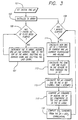
- FIG. 3 is a simplified flowchart of the operational steps implemented by the analyzer 27 in calibrating the CO 2 sensor of the sensor assembly 21.
- a value for the initial pH of the calibrant within the calibrant bag 17 is set. This value is determined based on the known amount of sodium bicarbonate injected into the bag from the syringe.
- a pH table that carries data characterizing each incremental amount, or slug, of calibrant within the IV set 19 is initialized. Initially, the data for each slug should correspond to the pH of the calibrant then carried within the bag.
- the analyzer 27 waits until the pump 13 has pumped a 1 ml slug of calibrant through the IV set 19.
- the pH table is updated at step 107 by shifting all of its entries one step downward and by inserting the current time and the current pH of the fluid within the calibrant bag 17 to the pH table's top-most entry.
- the lower-most entry is deleted, and this process continues indefinitely.
- the lower-most entry in the pH table indicates the time at which the slug of calibrant then adjacent to the CO 2 sensor first entered the IV set, and it further indicates the pH of that slug and the ambient temperature at the time of that entry into the IV set.
- the analyzer 27 While the analyzer 27 is implementing the procedures set forth in steps 105 and 107, as described above, it also determines, at step 109, on a time-interrupt basis, when one minute has elapsed. When it has, the program proceeds to step 111, where an updated pH is calculated for the calibrant still carried within the calibrant bag 17. This calculation takes into account the calculated pH from one minute earlier, the current temperature of the calibrant within the bag, as measured by the thermistor 33, and a calculation of the fluid volume remaining within the bag. It will be appreciated that the temperature of the calibrant within the bag affects the CO 2 diffusion rate and that the remaining calibrant volume affects the magnitude of the effect on pH of a given amount of CO 2 diffusion.
- step 113 the program calculates the amount of time the current slug of calibrant has been in transit within the IV set 19.
- step 115 the program calculates the actual change in pH caused by the calibrant's transit through the IV set. This change is affected, of course, by the dwell time within the IV set, as indicated by the data then carried in the lower-most entry in the IV set table. The change also is affected by the temperature of the calibrant within the IV set, which is assumed to be the arithmetic average of the current ambient temperature and the ambient temperature at the time the current slug of calibrant first entered the IV set.
- step 117 the program calculates the actual pH of the slug of calibrant then disposed adjacent to the CO 2 sensor, by combining the slug's calculated pH when it first entered the IV set 17 with the change in pH that was calculated to have occurred during its transit through the IV set.
- step 119 the program calculates a CO 2 standard based on a correlation of pH with pCO 2 .
- the relationship between pCO 2 and pH is given by the formula (1), set forth above.
- the O 2 sensor of the sensor assembly 21 also needs to be calibrated so that the signal it produces will have the requisite degree of accuracy.
- the amount of dissolved oxygen, i.e., pO 2 in the calibrant carried within the calibrant bag 17 ordinarily is close to that of the surrounding atmosphere.
- dissolved oxygen varies inversely with the temperature at which the fluid is equilibrated.
- the calibrant bag 17 is stored at ambient temperature for a minimum period, say for 24 hours, it is reasonable to assume that the calibrant within the bag will have substantially the same ambient temperature.
- the parameter pO 2 then can be calculated accurately based on that temperature. This calculated value generally is fairly accurate, unless the calibrant undergoes a wide and sudden swing in ambient temperature, such as can occur for example when the bag is transported wich the patient 25 from a relatively cold operating room (OR) to a relatively warm intensive care unit (ICU).
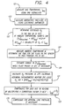
- FIG. 4 is a flowchart of the operational steps implemented by the analyzer 27 in determining the pO 2 of the calibrant located adjacent to the O 2 sensor of the sensor assembly 21.
- step 127 of the program the analyzer 27 measures the ambient temperature T amb and determines the accumulated transit time, t for the particular slug of calibrant that has just reached the O 2 sensor. Then, in step 129, the analyzer estimates the change in pO 2 that has occurred while that slug of calibrant has been disposed within the IV set 19. This change in pO 2 will result from any change in temperature from the temperature of the calibrant within the bag 17, and it is again determined using Henry's Law. This change in temperature is determined by monitoring the temperature of the IV set, which is assumed to correspond to the ambient temperature T amb , as indicated by the signal from the thermistor 35 (FIG. 1).
- F(T amb ,t) represents change in pO 2 during transit through the IV set, and it is determined empirically based on the geometry of the sensor assembly and on the speed at which the calibrant's temperature is raised.
- step 133 the analyzer 27 compensates for any loss due to heating by multiplying this pO 2 value by the following correction factor: (4) 1 - [k * (37 - T bag ) 1 ⁇ 2 ]
- the analyzer 27 compensates for the effects of any positive fluid pressure within the sensor assembly 21.
- a positive pressure might be required, for example, if the apparatus is being used to infuse the calibrant into an artery of the patient 25.
- the present invention provides an improved method for calibrating both a CO 2 sensor and an O 2 sensor that are part of an infusion fluid delivery and blood chemistry analysis apparatus.
- the method provides accurate calibration of these sensors by passing an infusible calibrant past them while correlating their resulting signals with calculated values of the calibrant's pCO 2 and pO 2 . These calculations are specially made based on predetermined diffusion rates for the CO 2 and O 2 from an infusion bag and from an IV set that connects the bag with the sensors.
Description
- This invention relates generally to the diagnostic testing of biological fluids and, more particularly, to the calibrating of sensors used in such testing.
- Low-cost, disposable, electrochemical electrode assemblies have special utility as part of infusion fluid delivery systems commonly used in hospital patient care. Such systems infuse nutrients, medications, and the like directly into the patient at a controlled rate and in precise quantities, for maximum effectiveness. Such infusion fluid delivery systems are connected to a patient via an intravenous (IV) port, in which a hollow needle/catheter assembly is inserted into a blood vessel of the patient and thereafter an infusion fluid is introduced into the vessel at a controlled rate, typically using a peristaltic pump. Blood chemistry monitoring systems that are combined with infusion fluid delivery systems of this kind use the IV port to periodically withdraw a blood sample into an electrode assembly, perform measurements of blood ion concentrations and the like, and then discard the blood or reinfuse it into the patient. The system then resumes delivery of the infusion fluid.
- The electrode assembly typically includes a reference electrode and a plurality of sensing electrodes, or sensors, that are each sensitive to a particular ion or species of interest. All of the electrodes are typically embedded in the base of the electrode assembly. For example, ion-selective electrodes generate electrical signals only in response to contact with the particular ion to which they are sensitive, and therefore provide selective measurement of the amount of that ion in the blood. This type of sensing electrode can be provided to measure, for example, blood calcium, hydrogen ion (i.e., pH), chloride, potassium, and sodium. In a differential measurement system, the reference electrode might be another ion-selective electrode (e.g., a chloride or sodium electrode) that is continuously exposed to a calibration or reference fluid. Alternatively, in a non-differential measurement system, a conventional reference electrode (which maintains a fixed potential when exposed either to reference fluid or to analyte) is required.
- Presently employed electrochemical sensors for clinical diagnostic applications fall into three categories: ac impedance sensors, amperometric sensors, and potentiometric sensors.
- An example of an ac impedance-type sensor is an hematocrit (Hct) sensor. Hematocrit is defined as the volume percent of red cells in the blood. Hematocrit can be determined by measuring the blood's ac impedance, using a pair of metal electrodes, typically at 1 kiloHertz (kHz).
- An amperometric sensor produces an electrical current that varies with the concentration of a specific component of interest. For example, oxygen partial pressure (pO2) and glucose (Glu) are commonly determined using amperometric sensors. An oxygen sensor assembly usually includes a working electrode formed from a noble metal, e.g., platinum or gold, and a suitable counter electrode formed of a different metal, e.g., silver/silver chloride. An oxygen-permeable, but liquid-impermeable, membrane is usually mounted over the sensor assembly, to separate the sample from the internal electrolyte and thereby avoid contamination. The sensor measures the limiting current of oxygen reduction at the working electrode according to the following equation:
- The glucose sensor is very similar in construction to the oxygen sensor. One difference is that a hydrophilic membrane with immobilized glucose oxidase (i.e., GOD) is used instead of the hydrophobic oxygen membrane. In the presence of glucose oxidase, the following reaction occurs:
- A potentiometric sensor produces an electrical voltage that varies with the species of interest. Ionic species, such as hydrogen ion (H+), sodium (Na+), potassium (K+), ionized calcium (Ca++) and chloride (Cl-), are commonly measured by ion-selective electrodes, a typical class of potentiometric sensors.
- The commonly used CO2 sensor, sometimes known as the Severinghaus electrode, also is a potentiometric sensor (and is, in fact, essentially a modified pH sensor). Typically, it consists of a pH electrode and a reference electrode, with both covered by a hydrophobic, gas-permeable/liquid-impermeable membrane such as silicone. A thin layer of weakly buffered internal electrolyte, e.g., 0.001M NaHCO3, is located between the hydrophobic membrane and the pH sensing membrane. Carbon dioxide in the sample eventually reaches equilibrium with the internal electrolyte, and it produces a pH shift according to the following equation:
- The accuracy of measurement obtained with any of the above-described sensors can be adversely affected by drift, particularly after exposure to biological fluids such as whole blood. Frequent calibration is therefore required. This is particularly true for gases such as pO2 and pCO2, because any change in the gas transport properties of the membrane can affect the sensor output.
- To this end, a number of calibration fluids are usually needed. This is because at least two different calibrant concentration levels are usually required to characterize a sensor. For a multi-parameter system, it is sometimes impossible to use the same two solutions to calibrate all of the sensors, due to concerns such as chemical incompatibility and long term stability. Moreover, since it is technically difficult to maintain pCO2 and pO2 constant at desired calibration levels, most conventional blood chemistry analyzers carry two gas cylinders and several bottles of reagents just to fulfill the calibration requirements. This makes the analyzers bulky and cumbersome to use.
- Attempts have been made to fill pre-tonometered liquid calibrants sealed into aluminum foil pouches under partial vacuum, as described in U.S. Pat. No. 4,734,184 to Burleigh. This approach has substantially reduced the blood chemistry analyzer's size and has improved the analyzer's portability. However, the contents of the pouch have a limited life after the pouch has been opened.
- The current trend has been to move away from bench top analyzers toward the use of bedside analyzers. Moreover, instead of taking samples from the patients, sensors either are miniaturized and inserted into a blood vessel (in vivo) or are constructed as part of a flow cell connected to the patient end of an existing vascular access port (ex vivo), to provide continuous monitoring of blood chemistry.
- The in vivo approach is conceptually more attractive, because it provides continuous results without intervention. However, it is considered more difficult to implement in practice, one major difficulty being blood clotting. Blood compatibility also has been a challenging issue. Even with a short term solution in hand, once sensors have been placed in the blood stream, repeated calibration becomes very difficult.
- The ex vivo approach, originally described in U.S. Pat. No. 4,573,968 to Parker, employs a control unit to periodically draw a small amount of blood into contact with sensors that are incorporated into an in-line flow cell. After a measurement has been taken, the control unit resumes delivering physiological saline into the blood vessel. As a result, the blood drawn is effectively flushed back into the patient and the sensors are washed clean. U.S. Pat. No. 4,535,786 to Kater discloses a method to use an infusible IV saline solution to calibrate ionic species in the biological fluid. However, Kater fails to address the calibration of species such as pO2 and pCO2.
- As mentioned above, blood chemistry sensors ordinarily require frequent calibration to maintain the accuracy of measurement. The calibration of pH and pCO2 sensors remains a particular challenge. In aqueous solutions, these two parameters are inter-related by the following equation:
- U.S. Pat. No. 4,736,748 to Nakamura suggests that simultaneous calibration for Na+, K+, Ca++, glucose, and hematocrit can be carried out using Lactated Ringer's solution with added glucose. However, such a solution could not be used for pH, pCO2 and/or pO2 calibration, because the solution has no well defined pH value or pO2 value, and it contains essentially no CO2. Indeed, since the amount of oxygen dissolved in Lactated Ringer's solution is not fixed (being a function of ambient temperature and barometric pressure -- parameters which Nakamura does not contemplate monitoring), the patent fails to teach how to use the solution as an oxygen calibrant.
- While the Burleigh patent identified above describes a solution that can be used for calibrating CO2, the solution does not appear to be infusible. The patent fails to provide any guidance as to suitable calibration solutions for use with combined infusion fluid delivery/blood chemistry measurement system.
- U.S. Pat. No. 5,132,000 to Sone et al. is similar to the Burleigh patent, in that it describes solutions that can be used for calibrating CO2-containing solutions. However, the solutions do not appear to be infusible.
- U.S. Patent No. 5,505,828 to Wong et al. describes a calibration solution that is useful for calibrating an array of sensors capable of simultaneously measuring several blood chemistry parameters, including pCO2 and p2O, pH, sodium, potassium, ionized calcium, ionized magnesium, chloride, glucose, lactate, and hematocrit. Moreover, the solution is infusible, whereby it can facilitate calibration on a regular basis of all the sensors in the array, which is in constant fluid communication with the body.
- The Wong et al. calibration solution works well for periods of time of up to about 8 hours. However, over longer periods of time, e.g., 12-24 hours, the solution's pH value will rise excessively, and its corresponding pCO2 will drop excessively. This is due primarily to the diffusion of CO2 from the infusion bag that initially carries the solution and from the IV set that carries the solution from the infusion bag to the sensor array. This variation in concentration can lead to significant calibration errors.
- The Wong et al. calibration solution can function satisfactorily to calibrate pO2, because concentration of O2 in the solution is substantially the same as the concentration of O2 in the atmosphere and because O therefore will not diffuse from the infusion bag or the IV set. However, the amount of dissolved O2 in the solution varies inversely with the solution's temperature. Consequently, if the solution delivered to the sensor array undergoes a sudden and significant temperature change, some of the dissolved O2 will come out of solution and calibration errors can arise.
- It should, therefore, be appreciated that there is a need for an improved method of calibrating sensors capable of measuring several blood chemistry parameters, including pH, pCO2 and O2, which can accommodate variations in the pCO2 of a calibration solution due to diffusion of CO2 from the solution's container, and which can accommodate significant variations in the temperature of the solution delivered to the sensors. The present invention fulfills this need.
- The present invention resides in a method for calibrating a sensor of a kind that measures the value of a predetermined parameter (e.g., CO2 partial pressure) of a test fluid such as blood, the method reliably compensating for expected variations over time in the value of the parameter in a calibration solution. The parameter of the calibration solution has a predetermined initial value, and the solution is initially located within a container that is configured to allow the value of that parameter to vary over time in a predetermined manner. The sensor to be calibrated is exposed to calibration solution supplied from the container, whereupon the sensor produces a calibration solution signal. The value of the parameter in the calibration solution supplied to the sensor is calculated based on its expected variation over time, and this calculated concentration is then compared with the calibration solution signal actually produced by the sensor, to produce a calibration factor. Further, the sensor then is exposed to the test fluid, whereupon the sensor produces a test fluid signal. Finally, the test fluid signal is adjusted in accordance with the calibration factor.
- The method of the invention has particular utility as part of an infusion fluid delivery and blood chemistry monitoring system, in which a pump ordinarily pumps the calibration solution from the container to a patient, via a sensor assembly that houses the sensor, whereupon the sensor produces the calibration solution signal. Periodically, the pump reverses its direction and draws blood from the patient into the sensor assembly, whereupon the sensor produces the test fluid signal.
- The method is suitable for use in measuring the value of any parameter whose value in the calibration solution is subject to variation over time. It can be used, for example, with sensors that are sensitive to CO2 partial pressure, pH, and O2 pressure. CO2 partial pressure and pH are subject to variation for their initial values, because the container has a porosity that allows CO2 to escape from the solution until its partial pressure equilibrates with the CO2 partial pressure of the surrounding atmosphere. O2 partial pressure is subject to variation from its initial value according to temperature variations in the solution.
- In some cases, the container for the calibration solution includes a flexible bag and an intravenous line. The flexible bag allows CO2 to escape over time from the calibration solution it carries in a first predetermined manner, and the intravenous line allows CO2 to escape over time from the calibration solution it carries in a second predetermined manner. In this case, when a CO2 sensor is to be calibrated, the step of calculating includes calculating the concentration of CO2 in the calibration solution supplied to the CO2 sensor based on its expected escape over time from both the flexible bag and the intravenous line. Calculating also includes determining the time durations the calibration solution supplied to the CO2 sensor has dwelled in both the flexible bag and the intravenous line. Calculating further includes measuring the temperature of the calibration solution in the container and determining the expected escape of CO2 over time based on the measured temperature.
- When the method is being used also to calibrate a pH sensor by compensating for variations In another more detailed feature of the invention, in the pH of the calibration solution due to expected variations in the CO2 partial pressure of the solution. In this case, the pH sensor is exposed to the calibration solution, whereupon the pH sensor produces a calibration solution pH signal, and the pH of the calibration solution supplied to the pH sensor is calculated based on the expected escape of CO2 from the container over time. The calculated pH is then compared with the calibration solution pH signal actually produced by the pH sensor, to produce a pH calibration factor. The pH sensor also is exposed to the test fluid, whereupon the sensor produces a test fluid pH signal. Finally, the test fluid pH signal is adjusted in accordance with the pH calibration factor.
- Other features and advantages of the present invention should become apparent from the following description of the preferred method, taken in conjunction with the accompanying drawings, which disclose by way of example the principles of the invention.
-
- FIG. 1 is a simplified schematic diagram of a combination infusion fluid delivery and blood chemistry analysis apparatus useful in the practice of the present invention.
- FIG. 2 is a graph depicting a typical increase over time in the pH of the infusion/calibration fluid adjacent to the CO2 sensor of the sensor assembly of FIG. 1, due to the diffusion of carbon dioxide (CO2) from the fluid bag and intravenous (IV) set.
- FIG. 3 is a simplified flowchart of the operational steps followed by the analyzer in calibrating the CO2 sensor and the pH sensor of the sensor assembly of FIG. 1.
- FIG. 4 is a simplified flowchart of the operational steps followed by the analyzer in calibrating the O2 sensor of the sensor assembly of FIG. 1.
-
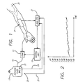
- With reference now to the drawings, and particularly to FIG. 1, there is shown a combination infusion fluid delivery and blood chemistry analysis apparatus 11 useful in measuring various parameters of a patient's blood. The apparatus includes a
peristaltic infusion pump 13 that is controllably conditioned by acontrol unit 15 so as to pump an infusion/calibration fluid, or calibrant, from aninfusion fluid bag 17 through an intravenous (IV) set orline 19, asensor assembly 21, and a needle/catheter assembly 23 to thepatient 25. The control unit periodically conditions the pump to reverse its pumping direction and draw a predetermined amount of blood from the patient back through the needle/catheter assembly to the sensor assembly. After the sensor assembly has measured various parameters of the drawn blood, and these measurements have been stored and processed by ananalyzer 27, the control unit conditions the pump to purge the blood from the sensor assembly back into the patient, and then to resume pumping the calibrant at its original controlled rate. - The
sensor assembly 21 includes several individual sensors for measuring any of a number of various blood chemistry parameters. Such parameters can include, for example, hematocrit, glucose concentration, and various ionic concentrations such as sodium ion, potassium ion, calcium ion, and chloride. The individual sensors of the sensor assembly also can measure such blood chemistry parameters as pH, carbon dioxide partial pressure (pCO2), and oxygen partial pressure (pO2). - The various sensors of the
sensor assembly 21 must be calibrated, for the signals they produce to have the requisite degree of accuracy. Calibration of the ion-sensitive sensors is achieved by formulating the calibrant initially carried in thebag 17 to include prescribed concentrations of various ions, including hydrogen, sodium, potassium, calcium and chloride. An analyzer monitors the voltage or current signals produced by these sensors when the calibrant is being pumped through the sensor assembly, so that the sensors' sensitivities can properly be characterized and calibrated. - Calibrating the CO2 sensor of the
sensor assembly 21 has in the past been a particularly difficult problem, typically requiring the use of bulky gas cylinders and bottles of reagents. An improved technique is disclosed in U.S. Patent No. 5,330,634 to Wong et al., wherein a special infusible calibration solution incorporates an amount of sodium bicarbonate effective to provide a prescribed initial concentration of HCO3 - in the range of about 1 to 100 mm/L. The sodium bicarbonate is introduced into the solution from a syringe that is packaged within a gas-impermeable pouch. - The calibration solution disclosed in the Wong et al. patent works well for time periods of up to about 8 hours; however, over longer periods of time, e.g., 12 to 24 hours, the solution's pH value will rise excessively, and its corresponding pCO2 will drop excessively. This is due primarily to the diffusion of CO2 from the
bag 17 that initially carries the solution and from the IV set 19 that carries the solution from the bag to thesensor assembly 21. Such diffusion necessarily occurs because the partial pressure of the CO2 in the calibration solution is initially substantially higher than that of the CO2 in the surrounding atmosphere. This variation in concentration has led to significant calibration errors. - A complicating factor in ascertaining the effect on calibration of this CO2 diffusion is that the diffusion rate from the
bag 17 is different from the diffusion rate from the IV set 19, which connects the bag with thesensor assembly 21. Generally, because of the substantially greater ratio of surface area to volume in the IV set, CO2 diffuses substantially faster from the it than from the infusion fluid bag. - FIG. 2 is a graph depicting the rise over time in pH of the calibrant located immediately adjacent to the CO2 sensor of the
sensor assembly 21, due to the diffusion of CO2 from the calibrant within both thebag 17 and the IV set 19. It will be noted that the pH of the calibrant located adjacent to the CO2 sensor normally rises at a slow, steady rate while thepump 13 pumps the fluid through the IV set and sensor assembly. During this time, the pH of the calibrant remaining within the bag likewise will rise, but at a significantly slower rate. - It further will be noted in FIG. 2 that, when the pump draws a blood sample from the
patient 25 and then purges that sample back into the patient, a fresh supply of calibrant will be moved from thebag 17 into the position adjacent to the CO2 sensor. The pH of that fresh supply of fluid will be lower than that of the calibrant that was injected into the patient by the purge; however, that lower pH will be slightly higher than the prior sample's initial pH, because of diffusion of CO2 from the bag. - The apparatus 11 of the invention overcomes the problem of CO2 diffusion by incorporating such diffusion into a calculation of the expected pCO2 of the calibrant that is at any time disposed adjacent to the CO2 sensor of the
sensor assembly 21. A theoretical, multi-compartment model is provided for the IV set 19, whereby theanalyzer 27 maintains a running log of the status of each incremental amount of calibrant in the IV set. Conveniently, the calibrant in the IV set can be divided into incremental amounts, or slugs, of 1 ml each. - The calculation of pCO2 for the slug of calibrant that finally reaches the CO2 sensor of the
sensor assembly 21 takes into account: 1) the diffusion coefficient for thecalibrant bag 17, 2) the elapsed time in the bag, 3) the diffusion coefficient for the IV set 19, and 4) the accumulated transit time in the IV set. The transit time in the IV set can vary widely depending on the duty cycle involved, ranging from as little as about 10 ml/hour during the normal slow pumping, to as much as 900 ml/hour during purge. - The calculation of pCO2 for the slug of calibrant that finally reaches the CO2 sensor also takes into account the temperature of the calibrant within the
bag 17 and the temperature of the ambient atmosphere, which is assumed to be the same as that of the IV set 19. The ambient temperature generally is subject to greater variation than is the temperature of the bag. The signal produced by the CO2 sensor generally varies directly with the temperature of the adjacent fluid. Signals indicative of bag temperature and ambient temperature are provided onlines temperature sensors - Thus, each time the CO2 sensor is to be calibrated, the pCO2 of the particular incremental amount of calibrant then disposed adjacent to the CO2 sensor of the
sensor assembly 21 is calculated and correlated with the electrical signal then being produced by the sensor. This provides an indication of the CO2 sensor's sensitivity and provides a calibration factor that can be used subsequently to adjust the signal produced when the patient's blood is withdrawn into the sensor assembly. - The pH sensor of the
sensor assembly 21 is calibrated in an identical manner. The pH of the calibrant generally will vary in a predetermined, repeatable fashion with the fluid's pCO2. The relationship is given by the following formula: - It has been determined that an IV set 19 newly put into use will absorb a substantial amount of CO2 from the calibrant during the first one to two hours. To minimize the adverse effects of this absorption, it is desirable to pre-condition the IV set to the same pCO2 and pO2 atmosphere as that of the calibrant. Specifically, this can be achieved most conveniently by packaging the IV set in an atmosphere of about 0.5%-to-1.0% CO2, 21% O2, and the balance N2, sealed within a gas-impermeable pouch.
- It also has been determined that the initial pH and pCO2 of the calibrant are determined primarily by the pH and pCO2 of the sodium bicarbonate syringe. It is desirable to control these levels so that the apparatus can initiate its operation each time at the same levels. To this end, it is considered desirable to store the syringe in an atmosphere having a predetermined CO2 level, to stabilize the syringe's pH and CO2 levels, and then to seal the syringe in a gas-impermeable pouch. The ideal gas atmosphere is considered to be 50% ± 20% CO2, with the balance N2.
- FIG. 3 is a simplified flowchart of the operational steps implemented by the
analyzer 27 in calibrating the CO2 sensor of thesensor assembly 21. In aninitial step 101 of the calibration program, a value for the initial pH of the calibrant within thecalibrant bag 17 is set. This value is determined based on the known amount of sodium bicarbonate injected into the bag from the syringe. Thereafter, instep 103, a pH table that carries data characterizing each incremental amount, or slug, of calibrant within the IV set 19 is initialized. Initially, the data for each slug should correspond to the pH of the calibrant then carried within the bag. - In a
subsequent step 105, theanalyzer 27 waits until thepump 13 has pumped a 1 ml slug of calibrant through the IV set 19. When that has occurred, the pH table is updated atstep 107 by shifting all of its entries one step downward and by inserting the current time and the current pH of the fluid within thecalibrant bag 17 to the pH table's top-most entry. The lower-most entry is deleted, and this process continues indefinitely. Thus, at any particular time, the lower-most entry in the pH table indicates the time at which the slug of calibrant then adjacent to the CO2 sensor first entered the IV set, and it further indicates the pH of that slug and the ambient temperature at the time of that entry into the IV set. - While the
analyzer 27 is implementing the procedures set forth insteps step 109, on a time-interrupt basis, when one minute has elapsed. When it has, the program proceeds to step 111, where an updated pH is calculated for the calibrant still carried within thecalibrant bag 17. This calculation takes into account the calculated pH from one minute earlier, the current temperature of the calibrant within the bag, as measured by thethermistor 33, and a calculation of the fluid volume remaining within the bag. It will be appreciated that the temperature of the calibrant within the bag affects the CO2 diffusion rate and that the remaining calibrant volume affects the magnitude of the effect on pH of a given amount of CO2 diffusion. - Thereafter, in
step 113, the program calculates the amount of time the current slug of calibrant has been in transit within the IV set 19. Then, instep 115, the program calculates the actual change in pH caused by the calibrant's transit through the IV set. This change is affected, of course, by the dwell time within the IV set, as indicated by the data then carried in the lower-most entry in the IV set table. The change also is affected by the temperature of the calibrant within the IV set, which is assumed to be the arithmetic average of the current ambient temperature and the ambient temperature at the time the current slug of calibrant first entered the IV set. - Thereafter, in
step 117, the program calculates the actual pH of the slug of calibrant then disposed adjacent to the CO2 sensor, by combining the slug's calculated pH when it first entered the IV set 17 with the change in pH that was calculated to have occurred during its transit through the IV set. Finally, instep 119, the program calculates a CO2 standard based on a correlation of pH with pCO2. The relationship between pCO2 and pH is given by the formula (1), set forth above. - As mentioned above, the O2 sensor of the
sensor assembly 21 also needs to be calibrated so that the signal it produces will have the requisite degree of accuracy. In this case, the amount of dissolved oxygen, i.e., pO2, in the calibrant carried within thecalibrant bag 17 ordinarily is close to that of the surrounding atmosphere. In addition, according to Henry's Law, dissolved oxygen varies inversely with the temperature at which the fluid is equilibrated. - If the
calibrant bag 17 is stored at ambient temperature for a minimum period, say for 24 hours, it is reasonable to assume that the calibrant within the bag will have substantially the same ambient temperature. The parameter pO2 then can be calculated accurately based on that temperature. This calculated value generally is fairly accurate, unless the calibrant undergoes a wide and sudden swing in ambient temperature, such as can occur for example when the bag is transported wich the patient 25 from a relatively cold operating room (OR) to a relatively warm intensive care unit (ICU). - In that case, less oxygen can remain dissolved in the calibrant, so oxygen bubbles will form and attempt to diffuse outwardly through the
calibrant bag 17 and the IV set 19. In some cases, however, an equilibrium at the higher temperature will not be reached before the calibrant reaches thesensor assembly 21, where further diffusion of oxygen is prevented because of the assembly's material. The calibrant within the assembly, therefore, will be supersaturated and will carry an excess O2 partial pressure. - To overcome this problem, a special algorithm is used to account for the excess pO2 during calibration of the O2 sensor. This algorithm is depicted schematically in FIG. 4, which is a flowchart of the operational steps implemented by the
analyzer 27 in determining the pO2 of the calibrant located adjacent to the O2 sensor of thesensor assembly 21. - In carrying out the program, the
analyzer 27 instep 121 measures the temperature Tbag of the calibrant in thebag 17, using the thermistor 33 (FIG. 1), and instep 123 measures the barometric pressure P, using an electronic barometer (not shown in the drawings). Thereafter, instep 125, the analyzer determines the dissolved oxygen in the calibrant within the bag, using Henry's Law, as follows: - Thereafter, in
step 127 of the program, theanalyzer 27 measures the ambient temperature Tamb and determines the accumulated transit time, t for the particular slug of calibrant that has just reached the O2 sensor. Then, instep 129, the analyzer estimates the change in pO2 that has occurred while that slug of calibrant has been disposed within the IV set 19. This change in pO2 will result from any change in temperature from the temperature of the calibrant within thebag 17, and it is again determined using Henry's Law. This change in temperature is determined by monitoring the temperature of the IV set, which is assumed to correspond to the ambient temperature Tamb, as indicated by the signal from the thermistor 35 (FIG. 1). - When the calibrant finally enters the
sensor assembly 21, its temperature is raised to about 37 °C by an electric heater (not shown) located within the assembly. This causes an immediate condition of O2 supersaturation, because the excess O2 cannot readily escape by diffusion. Atstep 131, theanalyzer 27 calculates the resulting pO2 using the following formula: - F(Tamb,t) represents change in pO2 during transit through the IV set, and it is determined empirically based on the geometry of the sensor assembly and on the speed at which the calibrant's temperature is raised.
- Thereafter, in
step 133, theanalyzer 27 compensates for any loss due to heating by multiplying this pO2 value by the following correction factor: - Finally, in
step 135 of the calibration program, theanalyzer 27 compensates for the effects of any positive fluid pressure within thesensor assembly 21. Such a positive pressure might be required, for example, if the apparatus is being used to infuse the calibrant into an artery of thepatient 25. - It should be appreciated from the foregoing description that the present invention provides an improved method for calibrating both a CO2 sensor and an O2 sensor that are part of an infusion fluid delivery and blood chemistry analysis apparatus. The method provides accurate calibration of these sensors by passing an infusible calibrant past them while correlating their resulting signals with calculated values of the calibrant's pCO2 and pO2. These calculations are specially made based on predetermined diffusion rates for the CO2 and O2 from an infusion bag and from an IV set that connects the bag with the sensors.
- Although the invention has been described in detail with reference only to the presently preferred method, those skilled in the art will appreciate that various modifications can be made without departing from the invention. Accordingly, the invention is defined only by the following claims.
Claims (10)
- A method for calibrating a sensor of a kind that measures a predetermined parameter of a test fluid, comprising:placing a calibration solution in a container, wherein a predetermined parameter of the calibration solution has a predetermined value, and wherein the container is configured such that the value of the predetermined parameter can vary over time in a predetermined manner;exposing the sensor to calibration solution supplied from the container, whereupon the sensor produces a calibration solution signal;calculating the value of the predetermined parameter of the calibration solution supplied to the sensor based on its expected variation over time, and comparing the calculated value with the calibration solution signal actually produced by the sensor, to produce a calibration factor;exposing the sensor to the test fluid, whereupon the sensor produces a test fluid signal; andadjusting the test fluid signal in accordance with the calibration factor, to produce a calibrated test fluid signal.
- A method as defined in claim 1, wherein:the calibration solution is infusible into a patient;the test fluid is blood;the method is implemented as part of an infusion fluid delivery apparatus that includes a sensor assembly that houses a CO2 sensor;the step of exposing the sensor to calibration solution includes pumping the calibration solution through the sensor assembly and into the patient; andthe step of exposing the sensor to the test fluid includes drawing blood from the patient into the sensor assembly.
- A method as defined in claim 1 or 2, wherein:the predetermined parameter of the test fluid to be measured is CO2 partial pressure;the sensor is configured to measure CO2 partial pressure;the calibration solution has a predetermined initial concentration of CO2;the container has a porosity that allows CO2 to escape from the calibration solution over time in a predetermined manner; andthe step of calculating includes calculating the concentration of CO2 in the calibration solution supplied to the CO2 sensor based on its expected escape from the container over time.
- A method as defined in any of claims 1-3, wherein:the sensor is configured to measure pH;the calibration solution has a predetermined initial concentration of CO2;the container has a porosity that allows the CO2 to escape from the calibration solution over time in a predetermined manner; andthe step of calculating includescalculating the concentration of CO2 in the calibration solution supplied to the pH sensor based on its expected escape from the container over time, andcalculating the pH of the calibration solution supplied to the pH sensor based on the calculated concentration of CO2.
- A method as defined in claim 1, 2, 3, or 4, wherein:the predetermined parameter of the test fluid to be measured is O2 partial pressure;the sensor is configured to measure O2 partial pressure;the calibration solution has a predetermined initial O2 partial pressure;the method further includes a step of measuring the temperature of the calibration solution carried by the container;the container has a porosity that allows the O2 partial pressure of the calibration solution it carries to vary over time according to variations in the temperature of the calibration solution; andthe step of calculating includes calculating the O2 partial pressure of the calibration solution supplied to the O2 sensor based on the measured temperature of the calibration solution.
- A method as defined in any of claims 1 - 5, wherein:the container for the calibration solution includes a flexible bag and an intravenous line;the flexible bag allows CO2 to escape over time from the calibration solution it carries in a first predetermined manner, and the intravenous line allows CO2 to escape over time from the calibration solution it carries in a second predetermined manner; andthe step of calculating includes calculating the concentration of CO2 in the calibration solution supplied to the CO2 sensor based on its expected escape over time from both the flexible bag and the intravenous line.
- A method as defined in any of claims 1 - 6, wherein the step of calculating includes determining the time durations the calibration solution supplied to the CO2 sensor has dwelled in both the flexible bag and the intravenous line.
- A method as defined in claim any of claims 1 - 7, wherein the step of calculating includes measuring the temperature of the calibration solution in the container and determining the expected escape of CO2 over time based on the measured temperature.
- A method as defined in any of claims 1 - 8, and further comprising
exposing a second, pH-responsive sensor to the calibration solution, whereupon the second, pH-responsive sensor produces a calibration solution pH signal;
calculating the pH of the calibration solution supplied to the second, pH-responsive sensor based on the expected escape of CO2 from the container over time, and comparing the calculated pH with the calibration solution pH signal actually produced by the second, pH-responsive sensor, to produce a pH calibration factor;
exposing the second, pH-responsive sensor to the test fluid, whereupon the second, pH-responsive sensor produces a test fluid pH signal; and
adjusting the test fluid pH signal in accordance with the pH calibration factor. - A method as defined in any of claims 1 - 9, and further comprising:measuring the pressure of the ambient environment; andadjusting the calculated value of O2 partial pressure of the calibration solution based on the measured pressure of the ambient environment.
Applications Claiming Priority (3)
| Application Number | Priority Date | Filing Date | Title |
|---|---|---|---|
| US78394497A | 1997-01-17 | 1997-01-17 | |
| US783944 | 1997-01-17 | ||
| PCT/US1998/000702 WO1998032013A1 (en) | 1997-01-17 | 1998-01-14 | Method for calibrating sensors used in diagnostic testing |
Publications (2)
| Publication Number | Publication Date |
|---|---|
| EP0958499A1 EP0958499A1 (en) | 1999-11-24 |
| EP0958499B1 true EP0958499B1 (en) | 2002-08-07 |
Family
ID=25130895
Family Applications (1)
| Application Number | Title | Priority Date | Filing Date |
|---|---|---|---|
| EP98905955A Expired - Lifetime EP0958499B1 (en) | 1997-01-17 | 1998-01-14 | Method for calibrating sensors used in diagnostic testing |
Country Status (5)
| Country | Link |
|---|---|
| US (1) | US6123827A (en) |
| EP (1) | EP0958499B1 (en) |
| JP (1) | JP3121356B2 (en) |
| DE (1) | DE69807042T2 (en) |
| WO (1) | WO1998032013A1 (en) |
Families Citing this family (123)
| Publication number | Priority date | Publication date | Assignee | Title |
|---|---|---|---|---|
| US6467953B1 (en) * | 1999-03-30 | 2002-10-22 | Medical Solutions, Inc. | Method and apparatus for monitoring temperature of intravenously delivered fluids and other medical items |
| US8974386B2 (en) | 1998-04-30 | 2015-03-10 | Abbott Diabetes Care Inc. | Analyte monitoring device and methods of use |
| US8480580B2 (en) | 1998-04-30 | 2013-07-09 | Abbott Diabetes Care Inc. | Analyte monitoring device and methods of use |
| US6175752B1 (en) | 1998-04-30 | 2001-01-16 | Therasense, Inc. | Analyte monitoring device and methods of use |
| US9066695B2 (en) | 1998-04-30 | 2015-06-30 | Abbott Diabetes Care Inc. | Analyte monitoring device and methods of use |
| US8465425B2 (en) | 1998-04-30 | 2013-06-18 | Abbott Diabetes Care Inc. | Analyte monitoring device and methods of use |
| US8688188B2 (en) | 1998-04-30 | 2014-04-01 | Abbott Diabetes Care Inc. | Analyte monitoring device and methods of use |
| US8346337B2 (en) | 1998-04-30 | 2013-01-01 | Abbott Diabetes Care Inc. | Analyte monitoring device and methods of use |
| US6949816B2 (en) | 2003-04-21 | 2005-09-27 | Motorola, Inc. | Semiconductor component having first surface area for electrically coupling to a semiconductor chip and second surface area for electrically coupling to a substrate, and method of manufacturing same |
| US6128519A (en) * | 1998-12-16 | 2000-10-03 | Pepex Biomedical, Llc | System and method for measuring a bioanalyte such as lactate |
| US7194371B1 (en) * | 2000-03-27 | 2007-03-20 | Cardiobeat.Com | Medical testing system and method |
| JP4781602B2 (en) * | 2000-06-01 | 2011-09-28 | イネオス ユーロープ リミテッド | New polyethylene film |
| US7232510B2 (en) * | 2000-11-30 | 2007-06-19 | Matsushita Electric Industrial Co., Ltd. | Biosensor, measuring instrument for biosensor, and method of quantifying substrate |
| US6560471B1 (en) | 2001-01-02 | 2003-05-06 | Therasense, Inc. | Analyte monitoring device and methods of use |
| US7238171B2 (en) | 2001-03-12 | 2007-07-03 | Medical Solutions, Inc. | Method and apparatus for controlling pressurized infusion and temperature of infused liquids |
| JP4512363B2 (en) * | 2001-08-22 | 2010-07-28 | インストゥルメンテイション ラボラトリー カンパニー | Method and apparatus for calibrating electrochemical sensors |
| US9247901B2 (en) | 2003-08-22 | 2016-02-02 | Dexcom, Inc. | Systems and methods for replacing signal artifacts in a glucose sensor data stream |
| US9282925B2 (en) | 2002-02-12 | 2016-03-15 | Dexcom, Inc. | Systems and methods for replacing signal artifacts in a glucose sensor data stream |
| US8010174B2 (en) | 2003-08-22 | 2011-08-30 | Dexcom, Inc. | Systems and methods for replacing signal artifacts in a glucose sensor data stream |
| US8260393B2 (en) | 2003-07-25 | 2012-09-04 | Dexcom, Inc. | Systems and methods for replacing signal data artifacts in a glucose sensor data stream |
| US8364229B2 (en) | 2003-07-25 | 2013-01-29 | Dexcom, Inc. | Analyte sensors having a signal-to-noise ratio substantially unaffected by non-constant noise |
| US7613491B2 (en) | 2002-05-22 | 2009-11-03 | Dexcom, Inc. | Silicone based membranes for use in implantable glucose sensors |
| AU2003234944A1 (en) * | 2002-08-27 | 2004-03-18 | Bayer Healthcare, Llc | Methods of Determining Glucose Concentration in Whole Blood Samples |
| US8282549B2 (en) | 2003-12-09 | 2012-10-09 | Dexcom, Inc. | Signal processing for continuous analyte sensor |
| US8423113B2 (en) | 2003-07-25 | 2013-04-16 | Dexcom, Inc. | Systems and methods for processing sensor data |
| US9763609B2 (en) | 2003-07-25 | 2017-09-19 | Dexcom, Inc. | Analyte sensors having a signal-to-noise ratio substantially unaffected by non-constant noise |
| US8845536B2 (en) | 2003-08-01 | 2014-09-30 | Dexcom, Inc. | Transcutaneous analyte sensor |
| US9135402B2 (en) | 2007-12-17 | 2015-09-15 | Dexcom, Inc. | Systems and methods for processing sensor data |
| US8676287B2 (en) | 2003-08-01 | 2014-03-18 | Dexcom, Inc. | System and methods for processing analyte sensor data |
| US8369919B2 (en) | 2003-08-01 | 2013-02-05 | Dexcom, Inc. | Systems and methods for processing sensor data |
| US20190357827A1 (en) | 2003-08-01 | 2019-11-28 | Dexcom, Inc. | Analyte sensor |
| US8626257B2 (en) | 2003-08-01 | 2014-01-07 | Dexcom, Inc. | Analyte sensor |
| US7591801B2 (en) | 2004-02-26 | 2009-09-22 | Dexcom, Inc. | Integrated delivery device for continuous glucose sensor |
| US8886273B2 (en) | 2003-08-01 | 2014-11-11 | Dexcom, Inc. | Analyte sensor |
| US7925321B2 (en) | 2003-08-01 | 2011-04-12 | Dexcom, Inc. | System and methods for processing analyte sensor data |
| US8060173B2 (en) | 2003-08-01 | 2011-11-15 | Dexcom, Inc. | System and methods for processing analyte sensor data |
| US8275437B2 (en) | 2003-08-01 | 2012-09-25 | Dexcom, Inc. | Transcutaneous analyte sensor |
| US8761856B2 (en) | 2003-08-01 | 2014-06-24 | Dexcom, Inc. | System and methods for processing analyte sensor data |
| US8160669B2 (en) | 2003-08-01 | 2012-04-17 | Dexcom, Inc. | Transcutaneous analyte sensor |
| US7774145B2 (en) | 2003-08-01 | 2010-08-10 | Dexcom, Inc. | Transcutaneous analyte sensor |
| US8233959B2 (en) | 2003-08-22 | 2012-07-31 | Dexcom, Inc. | Systems and methods for processing analyte sensor data |
| US7920906B2 (en) | 2005-03-10 | 2011-04-05 | Dexcom, Inc. | System and methods for processing analyte sensor data for sensor calibration |
| US20140121989A1 (en) | 2003-08-22 | 2014-05-01 | Dexcom, Inc. | Systems and methods for processing analyte sensor data |
| US9247900B2 (en) | 2004-07-13 | 2016-02-02 | Dexcom, Inc. | Analyte sensor |
| WO2005051170A2 (en) | 2003-11-19 | 2005-06-09 | Dexcom, Inc. | Integrated receiver for continuous analyte sensor |
| US11633133B2 (en) | 2003-12-05 | 2023-04-25 | Dexcom, Inc. | Dual electrode system for a continuous analyte sensor |
| US8532730B2 (en) | 2006-10-04 | 2013-09-10 | Dexcom, Inc. | Analyte sensor |
| DE602004029092D1 (en) | 2003-12-05 | 2010-10-21 | Dexcom Inc | CALIBRATION METHODS FOR A CONTINUOUSLY WORKING ANALYTIC SENSOR |
| US20080200788A1 (en) * | 2006-10-04 | 2008-08-21 | Dexcorn, Inc. | Analyte sensor |
| US8364230B2 (en) | 2006-10-04 | 2013-01-29 | Dexcom, Inc. | Analyte sensor |
| US8425416B2 (en) | 2006-10-04 | 2013-04-23 | Dexcom, Inc. | Analyte sensor |
| US8364231B2 (en) | 2006-10-04 | 2013-01-29 | Dexcom, Inc. | Analyte sensor |
| US8423114B2 (en) | 2006-10-04 | 2013-04-16 | Dexcom, Inc. | Dual electrode system for a continuous analyte sensor |
| US8425417B2 (en) | 2003-12-05 | 2013-04-23 | Dexcom, Inc. | Integrated device for continuous in vivo analyte detection and simultaneous control of an infusion device |
| US8287453B2 (en) | 2003-12-05 | 2012-10-16 | Dexcom, Inc. | Analyte sensor |
| US8808228B2 (en) | 2004-02-26 | 2014-08-19 | Dexcom, Inc. | Integrated medicament delivery device for use with continuous analyte sensor |
| US8565848B2 (en) | 2004-07-13 | 2013-10-22 | Dexcom, Inc. | Transcutaneous analyte sensor |
| US7946984B2 (en) | 2004-07-13 | 2011-05-24 | Dexcom, Inc. | Transcutaneous analyte sensor |
| WO2006127694A2 (en) | 2004-07-13 | 2006-11-30 | Dexcom, Inc. | Analyte sensor |
| US20060016700A1 (en) | 2004-07-13 | 2006-01-26 | Dexcom, Inc. | Transcutaneous analyte sensor |
| US7783333B2 (en) | 2004-07-13 | 2010-08-24 | Dexcom, Inc. | Transcutaneous medical device with variable stiffness |
| US8886272B2 (en) | 2004-07-13 | 2014-11-11 | Dexcom, Inc. | Analyte sensor |
| US8452368B2 (en) | 2004-07-13 | 2013-05-28 | Dexcom, Inc. | Transcutaneous analyte sensor |
| US7608042B2 (en) | 2004-09-29 | 2009-10-27 | Intellidx, Inc. | Blood monitoring system |
| US7972279B2 (en) | 2005-01-27 | 2011-07-05 | Instrumentation Laboratory Company | Method and system for managing patient data |
| US7722537B2 (en) * | 2005-02-14 | 2010-05-25 | Optiscan Biomedical Corp. | Method and apparatus for detection of multiple analytes |
| US20070123801A1 (en) * | 2005-11-28 | 2007-05-31 | Daniel Goldberger | Wearable, programmable automated blood testing system |
| US8092385B2 (en) | 2006-05-23 | 2012-01-10 | Intellidx, Inc. | Fluid access interface |
| WO2007143225A2 (en) | 2006-06-07 | 2007-12-13 | Abbott Diabetes Care, Inc. | Analyte monitoring system and method |
| US8275438B2 (en) | 2006-10-04 | 2012-09-25 | Dexcom, Inc. | Analyte sensor |
| US8478377B2 (en) | 2006-10-04 | 2013-07-02 | Dexcom, Inc. | Analyte sensor |
| US8447376B2 (en) | 2006-10-04 | 2013-05-21 | Dexcom, Inc. | Analyte sensor |
| US8298142B2 (en) | 2006-10-04 | 2012-10-30 | Dexcom, Inc. | Analyte sensor |
| US8562528B2 (en) | 2006-10-04 | 2013-10-22 | Dexcom, Inc. | Analyte sensor |
| US8449464B2 (en) | 2006-10-04 | 2013-05-28 | Dexcom, Inc. | Analyte sensor |
| US20200037874A1 (en) | 2007-05-18 | 2020-02-06 | Dexcom, Inc. | Analyte sensors having a signal-to-noise ratio substantially unaffected by non-constant noise |
| US8417311B2 (en) | 2008-09-12 | 2013-04-09 | Optiscan Biomedical Corporation | Fluid component analysis system and method for glucose monitoring and control |
| WO2008154312A1 (en) | 2007-06-08 | 2008-12-18 | Dexcom, Inc. | Integrated medicament delivery device for use with continuous analyte sensor |
| US9452258B2 (en) | 2007-10-09 | 2016-09-27 | Dexcom, Inc. | Integrated insulin delivery system with continuous glucose sensor |
| CA3105353A1 (en) | 2007-10-10 | 2009-04-16 | Optiscan Biomedical Corporation | Fluid component analysis system and method for glucose monitoring and control |
| US8417312B2 (en) | 2007-10-25 | 2013-04-09 | Dexcom, Inc. | Systems and methods for processing sensor data |
| US8290559B2 (en) | 2007-12-17 | 2012-10-16 | Dexcom, Inc. | Systems and methods for processing sensor data |
| WO2009105709A1 (en) | 2008-02-21 | 2009-08-27 | Dexcom, Inc. | Systems and methods for processing, transmitting and displaying sensor data |
| US8396528B2 (en) | 2008-03-25 | 2013-03-12 | Dexcom, Inc. | Analyte sensor |
| US8523797B2 (en) * | 2008-05-08 | 2013-09-03 | Hospira, Inc. | Automated point-of-care fluid testing device and method of using the same |
| US7959598B2 (en) | 2008-08-20 | 2011-06-14 | Asante Solutions, Inc. | Infusion pump systems and methods |
| US8753290B2 (en) | 2009-03-27 | 2014-06-17 | Intellectual Inspiration, Llc | Fluid transfer system and method |
| US9446194B2 (en) | 2009-03-27 | 2016-09-20 | Dexcom, Inc. | Methods and systems for promoting glucose management |
| DK3575796T3 (en) | 2011-04-15 | 2021-01-18 | Dexcom Inc | ADVANCED ANALYZE SENSOR CALIBRATION AND ERROR DETECTION |
| WO2012159040A2 (en) | 2011-05-19 | 2012-11-22 | Pepex Biomedical Inc. | Fluid management and patient monitoring system |
| US9211381B2 (en) | 2012-01-20 | 2015-12-15 | Medical Solutions, Inc. | Method and apparatus for controlling temperature of medical liquids |
| WO2014126964A1 (en) | 2013-02-15 | 2014-08-21 | Medical Solutions, Inc. | Plural medical item warming system and method for warming a plurality of medical items to desired temperatures |
| US20150133861A1 (en) | 2013-11-11 | 2015-05-14 | Kevin P. McLennan | Thermal management system and method for medical devices |
| GB2523989B (en) | 2014-01-30 | 2020-07-29 | Insulet Netherlands B V | Therapeutic product delivery system and method of pairing |
| US10143795B2 (en) | 2014-08-18 | 2018-12-04 | Icu Medical, Inc. | Intravenous pole integrated power, control, and communication system and method for an infusion pump |
| US10737024B2 (en) | 2015-02-18 | 2020-08-11 | Insulet Corporation | Fluid delivery and infusion devices, and methods of use thereof |
| AU2016267763B2 (en) | 2015-05-26 | 2021-07-08 | Icu Medical, Inc. | Disposable infusion fluid delivery device for programmable large volume drug delivery |
| CA2996468A1 (en) * | 2015-10-30 | 2017-05-04 | F. Hoffmann-La Roche Ag | Identification of calibration deviations of ph-measuring devices |
| WO2017123525A1 (en) | 2016-01-13 | 2017-07-20 | Bigfoot Biomedical, Inc. | User interface for diabetes management system |
| EP3453414A1 (en) | 2016-01-14 | 2019-03-13 | Bigfoot Biomedical, Inc. | Adjusting insulin delivery rates |
| EP3515535A1 (en) | 2016-09-23 | 2019-07-31 | Insulet Corporation | Fluid delivery device with sensor |
| CN109983341B (en) * | 2016-12-07 | 2020-09-08 | 雷迪奥米特医学公司 | System and method for estimating temperature of a liquid sample |
| US10552580B2 (en) * | 2017-02-07 | 2020-02-04 | Medtronic Minimed, Inc. | Infusion system consumables and related calibration methods |
| US11331022B2 (en) | 2017-10-24 | 2022-05-17 | Dexcom, Inc. | Pre-connected analyte sensors |
| US20190120785A1 (en) | 2017-10-24 | 2019-04-25 | Dexcom, Inc. | Pre-connected analyte sensors |
| USD928199S1 (en) | 2018-04-02 | 2021-08-17 | Bigfoot Biomedical, Inc. | Medication delivery device with icons |
| CN112236826A (en) | 2018-05-04 | 2021-01-15 | 英赛罗公司 | Safety constraints for drug delivery systems based on control algorithms |
| CA3112209C (en) | 2018-09-28 | 2023-08-29 | Insulet Corporation | Activity mode for artificial pancreas system |
| US11565039B2 (en) | 2018-10-11 | 2023-01-31 | Insulet Corporation | Event detection for drug delivery system |
| US20210048408A1 (en) * | 2019-08-12 | 2021-02-18 | Erbi Biosystems, Inc. | Methods to automatically calibrate ph sensors without sampling |
| USD939079S1 (en) | 2019-08-22 | 2021-12-21 | Icu Medical, Inc. | Infusion pump |
| US11801344B2 (en) | 2019-09-13 | 2023-10-31 | Insulet Corporation | Blood glucose rate of change modulation of meal and correction insulin bolus quantity |
| US11935637B2 (en) | 2019-09-27 | 2024-03-19 | Insulet Corporation | Onboarding and total daily insulin adaptivity |
| US11833329B2 (en) | 2019-12-20 | 2023-12-05 | Insulet Corporation | Techniques for improved automatic drug delivery performance using delivery tendencies from past delivery history and use patterns |
| US11551802B2 (en) | 2020-02-11 | 2023-01-10 | Insulet Corporation | Early meal detection and calorie intake detection |
| US11547800B2 (en) | 2020-02-12 | 2023-01-10 | Insulet Corporation | User parameter dependent cost function for personalized reduction of hypoglycemia and/or hyperglycemia in a closed loop artificial pancreas system |
| US11324889B2 (en) | 2020-02-14 | 2022-05-10 | Insulet Corporation | Compensation for missing readings from a glucose monitor in an automated insulin delivery system |
| US11607493B2 (en) | 2020-04-06 | 2023-03-21 | Insulet Corporation | Initial total daily insulin setting for user onboarding |
| US11684716B2 (en) | 2020-07-31 | 2023-06-27 | Insulet Corporation | Techniques to reduce risk of occlusions in drug delivery systems |
| US11904140B2 (en) | 2021-03-10 | 2024-02-20 | Insulet Corporation | Adaptable asymmetric medicament cost component in a control system for medicament delivery |
| WO2023049900A1 (en) | 2021-09-27 | 2023-03-30 | Insulet Corporation | Techniques enabling adaptation of parameters in aid systems by user input |
| US11439754B1 (en) | 2021-12-01 | 2022-09-13 | Insulet Corporation | Optimizing embedded formulations for drug delivery |
| WO2023152145A1 (en) * | 2022-02-11 | 2023-08-17 | Merck Patent Gmbh | Sensor measurement compensation in bioprocessing systems |
Family Cites Families (11)
| Publication number | Priority date | Publication date | Assignee | Title |
|---|---|---|---|---|
| US4573968A (en) * | 1983-08-16 | 1986-03-04 | Ivac Corporation | Infusion and blood chemistry monitoring system |
| US4786394A (en) * | 1985-08-29 | 1988-11-22 | Diamond Sensor Systems, Inc. | Apparatus for chemical measurement of blood characteristics |
| US4734184A (en) * | 1985-08-29 | 1988-03-29 | Diamond Sensor Systems, Inc. | Self-activating hydratable solid-state electrode apparatus |
| JPS6340532A (en) * | 1986-04-05 | 1988-02-20 | 日本光電工業株式会社 | Apparatus for monitoring blood component |
| US4871439A (en) * | 1987-02-05 | 1989-10-03 | Steven Enzer | Disposable self-calibratable electrode package |
| JPH0287055A (en) * | 1988-09-24 | 1990-03-27 | Terumo Corp | Calibrating solution of sensor and calibrating method therefor |
| US5165406A (en) * | 1990-09-13 | 1992-11-24 | Via Medical Corporation | Electrochemical sensor apparatus and method |
| US5246859A (en) * | 1990-10-15 | 1993-09-21 | Puritan-Bennett Corporation | Method of stabilizing a carbon dioxide sensor |
| US5271815A (en) * | 1991-12-26 | 1993-12-21 | Via Medical Corporation | Method for measuring glucose |
| US5330634A (en) * | 1992-08-28 | 1994-07-19 | Via Medical Corporation | Calibration solutions useful for analyses of biological fluids and methods employing same |
| US5431174A (en) * | 1994-04-04 | 1995-07-11 | Via Medical Corporation | Method of fluid delivery and collection |
-
1998
- 1998-01-14 JP JP10534496A patent/JP3121356B2/en not_active Expired - Fee Related
- 1998-01-14 DE DE69807042T patent/DE69807042T2/en not_active Expired - Fee Related
- 1998-01-14 WO PCT/US1998/000702 patent/WO1998032013A1/en active IP Right Grant
- 1998-01-14 EP EP98905955A patent/EP0958499B1/en not_active Expired - Lifetime
- 1998-09-03 US US09/146,986 patent/US6123827A/en not_active Expired - Lifetime
Also Published As
| Publication number | Publication date |
|---|---|
| JP3121356B2 (en) | 2000-12-25 |
| US6123827A (en) | 2000-09-26 |
| EP0958499A1 (en) | 1999-11-24 |
| JP2000509817A (en) | 2000-08-02 |
| DE69807042T2 (en) | 2003-02-06 |
| WO1998032013A1 (en) | 1998-07-23 |
| DE69807042D1 (en) | 2002-09-12 |
Similar Documents
| Publication | Publication Date | Title |
|---|---|---|
| EP0958499B1 (en) | Method for calibrating sensors used in diagnostic testing | |
| US5330634A (en) | Calibration solutions useful for analyses of biological fluids and methods employing same | |
| ES2307254T3 (en) | PROCEDURE FOR RESTORING THE FUNCTIONAL PROPERTIES OF AN ELECTROCHEMICAL SENSOR. | |
| US5271815A (en) | Method for measuring glucose | |
| US4818361A (en) | Combined pH and dissolved carbon dioxide gas sensor | |
| ES2533440T3 (en) | Cross-linked enzyme matrix | |
| US5697366A (en) | In situ calibration system for sensors located in a physiologic line | |
| ES2355333T3 (en) | METHOD AND APPLIANCE FOR CALIBRATING SENSORS. | |
| JP2004525369A (en) | Reference electrode | |
| JP2011033639A (en) | Composition and method for decelerating rate of oxygen loss from aqueous solution | |
| JPH0417049B2 (en) | ||
| JPS58152537A (en) | Continuous monitor apparatus of substance in blood | |
| JPH0368692B2 (en) | ||
| Horvai | 1. MEASUREMENTS OF PH 1.1. Introduction 1.2. Tools of pH Measurements 1.3. Standardization of pH Scales | |
| JPH0256889B2 (en) | ||
| Bergveld et al. | 2 Historical overview of various concepts for in vivo chemical analysis; from catheter-tip sensors to microdialysis lab-on-a-chip | |
| JPS60116332A (en) | Apparatus for measuring gas concentration in blood |
Legal Events
| Date | Code | Title | Description |
|---|---|---|---|
| PUAI | Public reference made under article 153(3) epc to a published international application that has entered the european phase |
Free format text: ORIGINAL CODE: 0009012 |
|
| 17P | Request for examination filed |
Effective date: 19990707 |
|
| AK | Designated contracting states |
Kind code of ref document: A1 Designated state(s): DE FR GB IT |
|
| RIN1 | Information on inventor provided before grant (corrected) |
Inventor name: RONG, DAITING Inventor name: SAVAGE, LAUREL Inventor name: BUSE, DAVID, A. Inventor name: WONG, DAVID, K. |
|
| GRAG | Despatch of communication of intention to grant |
Free format text: ORIGINAL CODE: EPIDOS AGRA |
|
| 17Q | First examination report despatched |
Effective date: 20011022 |
|
| GRAG | Despatch of communication of intention to grant |
Free format text: ORIGINAL CODE: EPIDOS AGRA |
|
| GRAH | Despatch of communication of intention to grant a patent |
Free format text: ORIGINAL CODE: EPIDOS IGRA |
|
| GRAH | Despatch of communication of intention to grant a patent |
Free format text: ORIGINAL CODE: EPIDOS IGRA |
|
| RAP1 | Party data changed (applicant data changed or rights of an application transferred) |
Owner name: METRACOR TECHNOLOGIES INC |
|
| GRAA | (expected) grant |
Free format text: ORIGINAL CODE: 0009210 |
|
| AK | Designated contracting states |
Kind code of ref document: B1 Designated state(s): DE FR GB IT |
|
| PG25 | Lapsed in a contracting state [announced via postgrant information from national office to epo] |
Ref country code: IT Free format text: LAPSE BECAUSE OF FAILURE TO SUBMIT A TRANSLATION OF THE DESCRIPTION OR TO PAY THE FEE WITHIN THE PRE;WARNING: LAPSES OF ITALIAN PATENTS WITH EFFECTIVE DATE BEFORE 2007 MAY HAVE OCCURRED AT ANY TIME BEFORE 2007. THE CORRECT EFFECTIVE DATE MAY BE DIFFERENT FROM THE ONE RECORDED.SCRIBED TIME-LIMIT Effective date: 20020807 Ref country code: FR Free format text: LAPSE BECAUSE OF NON-PAYMENT OF DUE FEES Effective date: 20020807 |
|
| REG | Reference to a national code |
Ref country code: GB Ref legal event code: FG4D |
|
| REF | Corresponds to: |
Ref document number: 69807042 Country of ref document: DE Date of ref document: 20020912 |
|
| PG25 | Lapsed in a contracting state [announced via postgrant information from national office to epo] |
Ref country code: GB Free format text: LAPSE BECAUSE OF NON-PAYMENT OF DUE FEES Effective date: 20030114 |
|
| PLBE | No opposition filed within time limit |
Free format text: ORIGINAL CODE: 0009261 |
|
| STAA | Information on the status of an ep patent application or granted ep patent |
Free format text: STATUS: NO OPPOSITION FILED WITHIN TIME LIMIT |
|
| 26N | No opposition filed |
Effective date: 20030508 |
|
| PG25 | Lapsed in a contracting state [announced via postgrant information from national office to epo] |
Ref country code: DE Free format text: LAPSE BECAUSE OF NON-PAYMENT OF DUE FEES Effective date: 20030801 |
|
| GBPC | Gb: european patent ceased through non-payment of renewal fee |