EP0957820B1 - Adjustable and retrievable graft and graft delivery system for stent-graft system - Google Patents
Adjustable and retrievable graft and graft delivery system for stent-graft system Download PDFInfo
- Publication number
- EP0957820B1 EP0957820B1 EP96926085A EP96926085A EP0957820B1 EP 0957820 B1 EP0957820 B1 EP 0957820B1 EP 96926085 A EP96926085 A EP 96926085A EP 96926085 A EP96926085 A EP 96926085A EP 0957820 B1 EP0957820 B1 EP 0957820B1
- Authority
- EP
- European Patent Office
- Prior art keywords
- graft
- loop
- manipulation
- manipulation lead
- stent
- Prior art date
- Legal status (The legal status is an assumption and is not a legal conclusion. Google has not performed a legal analysis and makes no representation as to the accuracy of the status listed.)
- Expired - Lifetime
Links
Images


Classifications
-
- A—HUMAN NECESSITIES
- A61—MEDICAL OR VETERINARY SCIENCE; HYGIENE
- A61F—FILTERS IMPLANTABLE INTO BLOOD VESSELS; PROSTHESES; DEVICES PROVIDING PATENCY TO, OR PREVENTING COLLAPSING OF, TUBULAR STRUCTURES OF THE BODY, e.g. STENTS; ORTHOPAEDIC, NURSING OR CONTRACEPTIVE DEVICES; FOMENTATION; TREATMENT OR PROTECTION OF EYES OR EARS; BANDAGES, DRESSINGS OR ABSORBENT PADS; FIRST-AID KITS
- A61F2/00—Filters implantable into blood vessels; Prostheses, i.e. artificial substitutes or replacements for parts of the body; Appliances for connecting them with the body; Devices providing patency to, or preventing collapsing of, tubular structures of the body, e.g. stents
- A61F2/02—Prostheses implantable into the body
- A61F2/04—Hollow or tubular parts of organs, e.g. bladders, tracheae, bronchi or bile ducts
- A61F2/06—Blood vessels
- A61F2/07—Stent-grafts
-
- A—HUMAN NECESSITIES
- A61—MEDICAL OR VETERINARY SCIENCE; HYGIENE
- A61F—FILTERS IMPLANTABLE INTO BLOOD VESSELS; PROSTHESES; DEVICES PROVIDING PATENCY TO, OR PREVENTING COLLAPSING OF, TUBULAR STRUCTURES OF THE BODY, e.g. STENTS; ORTHOPAEDIC, NURSING OR CONTRACEPTIVE DEVICES; FOMENTATION; TREATMENT OR PROTECTION OF EYES OR EARS; BANDAGES, DRESSINGS OR ABSORBENT PADS; FIRST-AID KITS
- A61F2/00—Filters implantable into blood vessels; Prostheses, i.e. artificial substitutes or replacements for parts of the body; Appliances for connecting them with the body; Devices providing patency to, or preventing collapsing of, tubular structures of the body, e.g. stents
- A61F2/95—Instruments specially adapted for placement or removal of stents or stent-grafts
- A61F2/962—Instruments specially adapted for placement or removal of stents or stent-grafts having an outer sleeve
- A61F2/966—Instruments specially adapted for placement or removal of stents or stent-grafts having an outer sleeve with relative longitudinal movement between outer sleeve and prosthesis, e.g. using a push rod
-
- A—HUMAN NECESSITIES
- A61—MEDICAL OR VETERINARY SCIENCE; HYGIENE
- A61F—FILTERS IMPLANTABLE INTO BLOOD VESSELS; PROSTHESES; DEVICES PROVIDING PATENCY TO, OR PREVENTING COLLAPSING OF, TUBULAR STRUCTURES OF THE BODY, e.g. STENTS; ORTHOPAEDIC, NURSING OR CONTRACEPTIVE DEVICES; FOMENTATION; TREATMENT OR PROTECTION OF EYES OR EARS; BANDAGES, DRESSINGS OR ABSORBENT PADS; FIRST-AID KITS
- A61F2/00—Filters implantable into blood vessels; Prostheses, i.e. artificial substitutes or replacements for parts of the body; Appliances for connecting them with the body; Devices providing patency to, or preventing collapsing of, tubular structures of the body, e.g. stents
- A61F2/82—Devices providing patency to, or preventing collapsing of, tubular structures of the body, e.g. stents
- A61F2/86—Stents in a form characterised by the wire-like elements; Stents in the form characterised by a net-like or mesh-like structure
- A61F2/89—Stents in a form characterised by the wire-like elements; Stents in the form characterised by a net-like or mesh-like structure the wire-like elements comprising two or more adjacent rings flexibly connected by separate members
-
- A—HUMAN NECESSITIES
- A61—MEDICAL OR VETERINARY SCIENCE; HYGIENE
- A61F—FILTERS IMPLANTABLE INTO BLOOD VESSELS; PROSTHESES; DEVICES PROVIDING PATENCY TO, OR PREVENTING COLLAPSING OF, TUBULAR STRUCTURES OF THE BODY, e.g. STENTS; ORTHOPAEDIC, NURSING OR CONTRACEPTIVE DEVICES; FOMENTATION; TREATMENT OR PROTECTION OF EYES OR EARS; BANDAGES, DRESSINGS OR ABSORBENT PADS; FIRST-AID KITS
- A61F2/00—Filters implantable into blood vessels; Prostheses, i.e. artificial substitutes or replacements for parts of the body; Appliances for connecting them with the body; Devices providing patency to, or preventing collapsing of, tubular structures of the body, e.g. stents
- A61F2/95—Instruments specially adapted for placement or removal of stents or stent-grafts
- A61F2002/9505—Instruments specially adapted for placement or removal of stents or stent-grafts having retaining means other than an outer sleeve, e.g. male-female connector between stent and instrument
- A61F2002/9511—Instruments specially adapted for placement or removal of stents or stent-grafts having retaining means other than an outer sleeve, e.g. male-female connector between stent and instrument the retaining means being filaments or wires
-
- A—HUMAN NECESSITIES
- A61—MEDICAL OR VETERINARY SCIENCE; HYGIENE
- A61F—FILTERS IMPLANTABLE INTO BLOOD VESSELS; PROSTHESES; DEVICES PROVIDING PATENCY TO, OR PREVENTING COLLAPSING OF, TUBULAR STRUCTURES OF THE BODY, e.g. STENTS; ORTHOPAEDIC, NURSING OR CONTRACEPTIVE DEVICES; FOMENTATION; TREATMENT OR PROTECTION OF EYES OR EARS; BANDAGES, DRESSINGS OR ABSORBENT PADS; FIRST-AID KITS
- A61F2/00—Filters implantable into blood vessels; Prostheses, i.e. artificial substitutes or replacements for parts of the body; Appliances for connecting them with the body; Devices providing patency to, or preventing collapsing of, tubular structures of the body, e.g. stents
- A61F2/95—Instruments specially adapted for placement or removal of stents or stent-grafts
- A61F2002/9528—Instruments specially adapted for placement or removal of stents or stent-grafts for retrieval of stents
-
- A—HUMAN NECESSITIES
- A61—MEDICAL OR VETERINARY SCIENCE; HYGIENE
- A61F—FILTERS IMPLANTABLE INTO BLOOD VESSELS; PROSTHESES; DEVICES PROVIDING PATENCY TO, OR PREVENTING COLLAPSING OF, TUBULAR STRUCTURES OF THE BODY, e.g. STENTS; ORTHOPAEDIC, NURSING OR CONTRACEPTIVE DEVICES; FOMENTATION; TREATMENT OR PROTECTION OF EYES OR EARS; BANDAGES, DRESSINGS OR ABSORBENT PADS; FIRST-AID KITS
- A61F2/00—Filters implantable into blood vessels; Prostheses, i.e. artificial substitutes or replacements for parts of the body; Appliances for connecting them with the body; Devices providing patency to, or preventing collapsing of, tubular structures of the body, e.g. stents
- A61F2/95—Instruments specially adapted for placement or removal of stents or stent-grafts
- A61F2002/9534—Instruments specially adapted for placement or removal of stents or stent-grafts for repositioning of stents
-
- A—HUMAN NECESSITIES
- A61—MEDICAL OR VETERINARY SCIENCE; HYGIENE
- A61F—FILTERS IMPLANTABLE INTO BLOOD VESSELS; PROSTHESES; DEVICES PROVIDING PATENCY TO, OR PREVENTING COLLAPSING OF, TUBULAR STRUCTURES OF THE BODY, e.g. STENTS; ORTHOPAEDIC, NURSING OR CONTRACEPTIVE DEVICES; FOMENTATION; TREATMENT OR PROTECTION OF EYES OR EARS; BANDAGES, DRESSINGS OR ABSORBENT PADS; FIRST-AID KITS
- A61F2/00—Filters implantable into blood vessels; Prostheses, i.e. artificial substitutes or replacements for parts of the body; Appliances for connecting them with the body; Devices providing patency to, or preventing collapsing of, tubular structures of the body, e.g. stents
- A61F2/95—Instruments specially adapted for placement or removal of stents or stent-grafts
- A61F2/962—Instruments specially adapted for placement or removal of stents or stent-grafts having an outer sleeve
- A61F2/966—Instruments specially adapted for placement or removal of stents or stent-grafts having an outer sleeve with relative longitudinal movement between outer sleeve and prosthesis, e.g. using a push rod
- A61F2002/9665—Instruments specially adapted for placement or removal of stents or stent-grafts having an outer sleeve with relative longitudinal movement between outer sleeve and prosthesis, e.g. using a push rod with additional retaining means
-
- A—HUMAN NECESSITIES
- A61—MEDICAL OR VETERINARY SCIENCE; HYGIENE
- A61F—FILTERS IMPLANTABLE INTO BLOOD VESSELS; PROSTHESES; DEVICES PROVIDING PATENCY TO, OR PREVENTING COLLAPSING OF, TUBULAR STRUCTURES OF THE BODY, e.g. STENTS; ORTHOPAEDIC, NURSING OR CONTRACEPTIVE DEVICES; FOMENTATION; TREATMENT OR PROTECTION OF EYES OR EARS; BANDAGES, DRESSINGS OR ABSORBENT PADS; FIRST-AID KITS
- A61F2230/00—Geometry of prostheses classified in groups A61F2/00 - A61F2/26 or A61F2/82 or A61F9/00 or A61F11/00 or subgroups thereof
- A61F2230/0002—Two-dimensional shapes, e.g. cross-sections
- A61F2230/0028—Shapes in the form of latin or greek characters
- A61F2230/0054—V-shaped
Definitions
- loops 11 and 12 comprise a nitinol (i.e., nickel-titanium) alloy wire.
- loops 11 and 12 may comprise a different metal alloy or a high strength plastic material. Loops 11 and 12 may be connected to the outer surface of graft 10, or alternatively may be connected to the interior surface of graft 10. In the latter case, the manipulation leads, described hereinafter, would be disposed within graft 10.
- Stent 51 suitable for use with graft 10 of the present invention may be of any design that will cause fixation of graft 10 to the walls of aorta 100.
- stent 51 may comprise an elastically balloon-expanded rolled sheet, as described, for example in Kreamer U.S. Patent Re. 34,327 , a plastically balloon-deformable wire mesh, as described for example, in Palmaz U.S. Patent 4,733,665 and Gianturco U.S. Patent 5,314,444 , a thermally activated stent as described in Dotter U.S. Patent 4,503,569 , or an elastically self-expanding stent as described in McNamara U.S. Patent 5,147,370 , the disclosures of which are incorporated herein by reference.
- Stents suitable for use with the graft system of the present invention preferably employ a delivery catheter having a diameter of about 9-10 French.
Abstract
Description
- The present invention relates generally to non-invasive techniques for repairing aneurysms occurring in hollow-body biological organs or vessels, for example, the abdominal aorta, and for repairing arterio-venous fistulas. More particularly, the present invention relates to methods and apparatus for repairing aneurysms and fistulas that permit adjustment and/or retrieval of the graft even after a deployment of the graft component of a stent-graft system.
- In recent years a number of non-invasive techniques have been developed to repair aneurysms occurring in hollow-body biological organs or vessels, for example, the abdominal aorta, using stent-graft techniques. These techniques generally seek to "reline" a flow path through the organ, for example, by fixing a graft across the weakened tissue of the aneurysm. The graft is then held in place with one or more stents, which may be implanted, for example, using a balloon catheter. Such arrangements are described, for example, in Parodi
U.S. Patent 5,219,355 , European Application No.0 461 791 , and ClouseU.S. Patent 5,211,658 . - A drawback common to such previously known methods and apparatus, especially those such as the Parodi and Clouse patents, is the inability to adjust or retrieve the graft once it has been deployed from an introducer catheter. Generally, deployment of the graft (or the stent in Clouse system) marks a point of no-return -- if the graft is determined to be in an inappropriate position, or the graft size is inadequate, it is not possible to abort the procedure.
- Thus, previously known methods and apparatus cannot, for example, adjust the placement of the graft relative to the portions of the organ or vessel proximal and distal to the aneurysm (i.e., the proximal neck and the distal cuff of the aneurysm) once the graft is deployed. Neither can such methods and apparatus correct for migration of the graft between its deployment and fixation of the graft to the organ or vessel walls via stents, etc. See, for example, the catalog of complications resulting from mispositioning and/or migration described in T. Chuter et al. in Endoluminal Vascular Prostheses, Little Brown & Co. (1995), Chapter 3 at , which is incorporated herein by reference.
- Another drawback of previously known stent-graft systems, for example, those systems having integrated grafts and stents, is the large diameter introducer catheters needed to deliver such systems. A typical previously known stent-graft system may include a central delivery shaft having a diameter of 1.5-1.75 mm, a deployment balloon having a thickness of 0.5-0.75 mm, an anchoring stent with a thickness of 0.3-0.6 mm, a synthetic graft with a thickness of 0.25-0.5 mm, and a delivery sheath having a thickness of 0.5-0.75 mm. The stacking of these thicknesses results in a combined thickness of 4-7 mm, which must be inserted through a vascular system generally having a diameter in a range of 5-7 mm.
- Not surprisingly, the large-diameter introducer catheters needed for such previously known stent-graft systems, for example, 22-26 French, create problems in delivering such systems transluminally via the femoral arteries, and the thicker diameters also reduce the clinician's ability to maneuver the stent-graft system into position along a tortuous path. See, for example, Chapter 3 of the foregoing text at pp. 40-41, 44 and 48, incorporated herein by reference, which describes spasm and delivery problems associated with the use of large introducer catheters employed with previously known stent-graft systems.
- In view of the foregoing, it would be desirable to provide graft apparatus and delivery devices for use in a stent-graft system for repairing an aneurysm that enable the graft position to be adjusted after deployment of the graft from an introducer catheter.
- It further would be desirable to provide graft apparatus and delivery devices for use in a stent-graft system for repairing aneurysms that enable the use of much smaller diameter introducer catheters than used with previously known stent-graft systems, thereby reducing problems associated with the use of large diameter introducer catheters.
- It also would be desirable to provide graft apparatus and delivery devices for use in stent-graft systems for repairing aneurysms that enable the graft to be entirely retrieved after initial deployment, for example, to be exchanged for a graft of a different size.
- In view of the foregoing, it is an object of this invention to provide graft apparatus and delivery devices for use in a stent-graft system for repairing aneurysms and fistulas that enable the graft position to be adjusted after deployment of the graft from an introducer catheter.
- It is a further object of the present invention to provide graft apparatus and delivery devices for use in a stent-graft system for repairing aneurysms and fistulas that enable the use of much smaller diameter introducer catheters than used with previously known stent-graft systems, thereby reducing problems associated with the use of large diameter introducer catheters.
- It is another object of this invention to provide graft apparatus and delivery devices for use in stent-graft systems suitable for excluding aneurysms in hollow-body organs and vessels other than the aorta, for example, in gastro-intestinal, respiratory, reproductive organ and urethral applications and elsewhere where it desirable to "reline" a hollow-body organ or vessel, and for use in treating arterio-venous fistulas.
- It is yet another object of this invention to provide graft apparatus and delivery devices for use in stent-graft systems for repairing aneurysms and fistulas that enable a graft to be entirely retrieved after initial deployment from an introducer catheter, for example, to be exchanged for a graft of a different size.
- These and other objects of the invention are accomplished in accordance with the principles of the invention by providing graft apparatus and delivery devices for use in stent-graft systems that provide the clinician with complete control over the location of the graft, even after the graft is completely deployed from an introducer catheter. Thus, if a graft is determined to be mispositioned, the clinician may adjust the graft, or if the size is thought to be inappropriate, the clinician may even completely withdraw the graft and substitute a graft of a different size.
- In accordance with the invention, the graft and stent components of a stent-graft system are separately delivered transluminally to the site of an aneurysm using small diameter catheters (e.g., 12-16 French for the graft, about 9-10 French for the stent). The graft component is removably engaged with proximal and distal manipulation leads that permit the location of the graft to be freely manipulated by the clinician after deployment from an introducer catheter. These manipulation leads even enable the graft to be fully retracted into its associated introducer catheter after deployment. The stent component of the system is likewise delivered transluminally to the site of the aneurysm via a small diameter introducer catheter, and permits use of a wide range of conventional stent designs to permanently fix the graft in position.
- The invention further includes alternative embodiments of graft delivery devices suitable for use with a graft constructed in accordance with the present invention. These delivery devices provide complete control of over positioning of the graft, and permit quick release of the graft once its permanent position is selected.
- Further features of the invention, its nature and various advantages will be more apparent from the accompanying drawings and the following detailed
-
-
FIGS. 1A, 1B and 1C are, respectively, illustrative views of the deployment of a graft and delivery device constructed in accordance with the methods and apparatus of the present invention. -
FIGS. 2A, 2B, 2C and 2D are, respectively, alternative embodiments for engaging the graft ofFIGS. 1 to the manipulation leads of a delivery device constructed in accordance with the present invention. -
FIG. 3 is an elevational view, partly in section, showing positioning of the graft ofFIGS. 1 being positioned in an abdominal aortic aneurysm. -
FIG. 4 is an elevational view, partly in section, showing deployment of the graft ofFIG. 3 . -
FIG. 5 is an elevational view of a graft constructed in accordance with the present invention, as permanently implanted in the aorta. -
FIGS. 6A, 6B and 6C are, respectively, an elevational view and detail views of an alternative embodiment of the graft and delivery device of the present invention. - The present invention provides apparatus for treatment of aneurysms occurring in hollow-body organs or vessels, and for the treatment of arterio-venous fistulas, that overcome certain limitations of previously known non-invasive methods. In particular, the apparatus of the present invention enables a clinician to adjust the positioning of a graft component of a stent-graft system once deployed from its associated introducer catheter, and even enable the clinician to entirely retrieve the graft should it be decided that a graft of a different size is required.
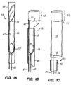
- Referring to
FIGS. 1A through 1C ,graft 10 and the proximal end ofdelivery system 15 constructed in accordance with the principles of the present invention are described. Graft 10 is preferably a polyester fabric, such as DACRON®, a registered trademark of the E.I. du Pont de Nemours Company, Wilmington, or other biocompatible material, such as PTFE (polytetrafluoroethylene) or tightly-woven wire mesh. One familiar to the art of non-invasive stent-graft technology will recognize that other suitable materials may be used in the construction ofgraft 10. - In accordance with the principles of the present invention,
graft 10 includes twoloops Loops graft 10, for example, by sutures, by incorporation into the wall ofgraft 10, by being weaved into the fabric ofgraft 10 or other suitable means. - In a first preferred embodiment,
loops loops Loops graft 10, or alternatively may be connected to the interior surface ofgraft 10. In the latter case, the manipulation leads, described hereinafter, would be disposed withingraft 10. - As will be understood from the description that follows,
loops graft 10. In addition, to assist inpositioning graft 10 within the aneurysm or arterio-venous fistula under fluoroscopic guidance,loops - Graft 10 is delivered transluminally to the site of an aneurysm in a hollow-body organ or vessel, for example, the abdominal aorta, while folded within
delivery system 15 comprising introducercatheter 20 and manipulation leads 21 and 22, described in greater detail hereinafter.Introducer catheter 20 is shown in outline only inFIGS. 1 so as to not obscure salient aspects of the invention.Introducer catheter 20 may be of conventional construction and, in accordance with the present invention, is of a size between 12 and 16 French. Manipulation leads 21 and 22 are preferably constructed of a durable yet sturdy material, such as a nickel-titanium alloy. - As shown in
FIGS. 1A to 1C ,loop 11 is releasably engaged tomanipulation lead 21, whileloop 12 is likewise releasably engaged tomanipulation lead 22. When folded withinintroducer catheter 20,loops FIG. 1B , whenintroducer catheter 20 is withdrawn in a distal direction, the proximal end ofgraft 10 andloop 11 are deployed from the catheter, causingloop 11 to resume an approximately circular shape. Asloop 11 recovers its original shape,graft 10 is opened from its folded shape. - Referring now to
FIG. 1C , whenintroducer catheter 20 is withdrawn further in the distal direction,loop 12 and the distal portion ofgraft 10 are also deployed. Whenloop 12 opens upon deployment,graft 10 is preferably completely unfolded. Whereas with previously known graft members, complete deployment of the graft (as inFIG. 1C ) would terminate the clinician's ability to adjust or retrieve the graft member, in accordance with the present invention,graft 10 remains coupled to manipulation leads 21 and 22. - Thus, even though
graft 10 is deployed, its position may be adjusted within the aneurysm, by pulling (or pushing) one or both of manipulation leads 21 and 22 in the proximal or distal directions. In addition, should the clinician determine thatgraft 10 is of inappropriate size, or should he for some other reason wish to abort the procedure,graft 10 may be completely recovered withinintroducer catheter 20 by advancingcatheter 20 in the proximal direction while retaining manipulation leads 21 and 22 against proximal movement.Graft 10 will accordingly be retracted withinintroducer catheter 20 as the catheter advances in the proximal direction. - In the illustrative embodiment of
FIGS. 1 ,loop 12 connected to the distal end ofgraft 10 is preferably located at or near the lower end of the graft to facilitate retraction ofgraft 10 withinintroducer catheter 20. By positioningloop 12 in this manner, it is expected that the possibility of inadvertently catchinggraft 10 onintroducer catheter 20 will be reduced, ensuring complete retrievability of the graft even if fully deployed. - On the other hand, in the embodiment of
FIGS. 1 ,loop 11 is preferably connected to the graft at a distance below the proximal edge ofgraft 10, thus creating an overhang region 13 (seeFIGS. 1B and 1C ) of approximately 15-20 mm. Overhang region may have a length of about two-thirds of the length of the stent to be used in fixinggraft 10 in place within the aorta. This positioning ofloop 11 ongraft 10 is expected to prevent interference betweenloop 11 and the stent to be implanted. - Alternatively, as described with respect to
FIGS. 2 , it may instead be desirable to omitoverhang region 13 so thatloop 11 is located at or near the proximal (upper) end ofgraft 10, so as to prevent potential flutter of the overhang when introduced into high flow rate environments. In thiscase loop 11 is captured and expanded by the proximal stent when it is deployed, andloop 11 includes elongated leads that traverse the length of the overhang and permit the engagement means to engageloop 11 at a point distal tooverhang region 13. - Turning now to
FIGS. 2A, 2B, 2C and 2D , several alternative embodiments are described for releasably engagingloops graft 10 to manipulation leads 21 and 22, respectively. For clarity, onlyloop 11 is discussed here, althoughloop 12 may include a similar engagement arrangement. - In
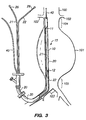
FIG. 2A ,loop 11 terminates inbeads 14 disposed on its ends.Manipulation lead 21 includesouter sheath 23,push wire 24 andball 25. As will of course be understood, the distal end ofmanipulation lead 21 extends outside of the patients' body via an introducer sheath. As seen inFIG. 3 , the distal ends of manipulation leads 21 and 22 each includemechanism 26, for example, a spring-loaded shaft, for releasing the grip of manipulation leads 21 and 22 onloops - Push
wire 24 is biased in a distal direction, so that whenbeads 14 ofloop 11 are inserted within the proximal end ofouter sheath 23,ball 25 captures the beads within the outer sheath, thus releasably engagingloop 11 tomanipulation lead 21. Whenmechanism 26 is later actuated, for example, by pushingpush wire 24 in a proximal direction,ball 25 is lifted away from the proximal end ofouter sheath 23, andbeads 14 andloop 11 are set free. - Accordingly,
manipulation lead 21 can be pulled in the proximal and distal directions to adjust the positioning of proximal end ofgraft 10 via its engagement withloop 11. Once the graft is in a desired position within the neck of the aneurysm,mechanism 26 is actuated to releaseloop 11.Loop 11 is retained on the outer surface ofgraft 10. Becausebeads 14 may be separately formed on the ends ofloop 11,loop 11 may be opened to an even larger diameter when a stent is expanded into position withingraft 10. - Referring now to
FIG. 2B , an alternative embodiment of the engagement means for couplingloop 11 tomanipulation lead 21 is described. As seen inFIG. 2B ,loop 11 is designed for placement at the proximal end ofgraft 10, thereby omittingoverhang region 13. Instead,loop 11 includes elongated leads 11a that extend distally for approximately the same length as the now omittedoverhang region 13, for example 15-20 mm, depending upon the type of stent to be used.Loop 11 therefore keeps the proximal end ofgraft 10 patent even in high flow environments, while elongated leads11a permit loop 11 to remain engaged withmanipulation lead 21 until after the proximal stent is fixed into position. - In the embodiment of
FIG. 2B , the ends of elongated leads 11a terminate in threaded region 14'.Manipulation device 21 includes outer sheath 23', wire 24' and threaded socket 25'. The distal end ofmanipulation lead 21 terminates in mechanism 26' that enables wire 24' to be rotated within outer sheath 23'. During deployment ofgraft 10, threaded portion 14' ofloop 11 is threadedly engaged with threaded socket 25'. Oncegraft 10 is in its desired position, the proximal stent is deployed. The clinician then operates mechanism 26' to rotate wire 24', thus unscrewing threaded portion 14' ofloop 11 from threaded socket 25'. Because elongated leads 11a extend distally beyond the distal end of the proximal stent,manipulation lead 21 may be uncoupled fromloop 11 without interfering with the deployed proximal stent. - With respect to
FIG. 2C , another alternative embodiment of an engagement means suitable for use withgraft 10 of the present invention is described. In this embodiment, again suitable for use withoutoverhang region 13,loop 11 terminates with elongated right-angled lengths 14''.Manipulation lead 21 includes outer sheath 23'', push wire 24'' and collet 25''. The distal end ofmanipulation lead 21 terminates in mechanism 26'', for example a spring-loaded shaft. - Collet 25'' is illustratively formed of four opposing members, while push wire 24'' is biased in a distal direction. This biasing of push wire 24'' causes the outer surfaces of the opposing members of collet 25'' to be urged against the inner surface of outer sheath 23'', thereby urging the opposing members comprising collet 25'' into contact with one another.
- To insert right-angled ends 14'' of
loop 11 into collet 25'', push wire 24'' is first urged in a proximal direction, relieving the contact forces between the opposing members of collet 25'' to permit right-angled ends 14'' to be inserted therebetween. Push wire is then permitted to return to its biased position, thereby capturing right-angled ends 14'' within collet 25'' and thus releasably engagingloop 11 tomanipulation lead 21. When mechanism 26'' is subsequently actuated (after deployment of graft 10), for example, by urging push wire 24'' in a proximal direction, the opposing members of collet 25'' relax their grip on right-angled ends 14'' ofloop 11, thus settingloop 11 free. - Referring now to
FIG 2D , a yet further alternative embodiment of an engagement means suitable for use with the present invention is described. InFIG. 2D ,loop 11 terminates in beads 14''' that are captured in snare 25''' connected to the proximal end of push wire 24'''.Manipulation lead 21 includes an actuation mechanism 26''' at its distal end that biases snare 25''' in a distal direction, thereby engaging beads 14''' within snare 25'''.Manipulation lead 21, including outer sheath 23''', snare 25''', beads 14''' andloop 11 are therefore movable as a unit in the proximal and distal directions, while actuation of mechanism 26''' causes snare 25''' to release beads 14'''. - The foregoing means of
coupling loops overhang region 13, orloop 11 could instead have elongated leads 11a, thereby enabling omission ofoverhang region 13. - Moreover,
graft 10 also may have integrated within it elastic fibers that assist the graft in opening once it is deployed. For such a graft, it would no longer be necessary forloops loops graft 10, for example, by cutting the wire at the distal end and pulling the entire length of wire out through the introducer sheath. - Referring now to
FIGS. 3-5 , a method of implanting a graft constructed in accordance with the present invention within an abdominal aorta aneurysm is described. As illustratively shown inFIG. 3 , graft 10 of the stent-graft system is disposed across the region ofaneurysm 101 inaorta 100, which is located betweenrenal arteries 102 andiliac arteries 103.Aneurysm 101 includes a proximal nondilated region ofaorta 100 above the aneurysm referred to as "proximal neck" 104, and a distal region just above the bifurcation foriliac arteries 103 referred to as "distal cuff" 105. -
Graft 10 includes proximal anddistal loops Graft 10 is threaded through a femoral artery inintroducer catheter 20 viaintroducer sheath 30 alongguidewire 40, so thatgraft 10 is positioned acrossaneurysm 101. In accordance with the present invention, graft 10 permits introducercatheter 20 to have a smaller diameter, for example 12-16 French, relative to previously known apparatus that generally use diameters greater than 21 French. The position ofintroducer catheter 20 withinaneurysm 101 may be determined using standard fluoroscopic techniques and a suitable high contrast agent onintroducer catheter 20 orgraft 10. - In
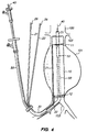
FIG. 4 ,graft 10 is shown fully deployed from introducer catheter 20 (which has been removed). Manipulation leads 21 and 22 are used to maneuvergraft 10 to a desired location acrossaneurysm 101, by moving manipulation leads 21 and 22 in the proximal and distal directions under fluoroscopic guidance. Whengraft 10 has been moved to a desired position,catheter 50 containing collapsedstent 51 anddeployment balloon 52 is inserted alongguidewire 40 so that the stent is positioned overlapping the proximal end ofgraft 10. As described hereinabove with respect toFIGS. 1A through 1C , the position ofgraft 10 may be adjusted, or the graft entirely withdrawn, at any point up to implantation ofproximal stent 51. -
Stent 51 suitable for use withgraft 10 of the present invention may be of any design that will cause fixation ofgraft 10 to the walls ofaorta 100. For example,stent 51 may comprise an elastically balloon-expanded rolled sheet, as described, for example inKreamer U.S. Patent Re. 34,327 , a plastically balloon-deformable wire mesh, as described for example, inPalmaz U.S. Patent 4,733,665 andGianturco U.S. Patent 5,314,444 , a thermally activated stent as described inDotter U.S. Patent 4,503,569 , or an elastically self-expanding stent as described inMcNamara U.S. Patent 5,147,370 , the disclosures of which are incorporated herein by reference. Stents suitable for use with the graft system of the present invention preferably employ a delivery catheter having a diameter of about 9-10 French. - Referring to
FIG. 5 , graft 10 ofFIG. 4 is shown affixed to the walls ofaorta 100 bystents Stents graft 10 and the walls ofaorta 100 throughintroducer catheter 20 as described above with respect toFIG. 4 . Alternatively, the delivery catheter andstents graft 10 via the femoral artery associated with the right branch of the iliac artery, or even from above via the brachial/carotid artery. - During placement of
stents graft 10. Either immediately before, or during, the expansion ofstent 51,mechanism 26 ofmanipulation lead 21 is actuated to releaseloop 11, and the manipulation lead is then withdrawn. - As will of course be apparent, releasing ends 14 of
loop 11 asstent 51 expands to fixgraft 10 in position permits the loop to increase in diameter to accommodate the expanding stent. Thus, as seen inFIG. 5 , a gap may develop betweenends 14 ofloop 11 as it is captured between the walls ofaorta 100 andgraft 10 by the expanding stent.Stent 54 is expanded in a manner similar to that forstent 51, withmanipulation lead 22 releasingloop 12 either before or during expansion ofstent 54. - Alternatively, if a sufficiently
long overhang 13 is provided forgraft 10, or if elongated leads 11a are instead provided ongraft 10 andloop 11 is connected at or near the proximal end ofgraft 10,stent 51 may be expanded into position prior to releasingloop 11 frommanipulation lead 21. Manipulation lead is then uncoupled fromloop 11 once the proximal stent has been deployed. - Referring now to
FIGS. 6A to 6C , a yet further alternative embodiment of the graft and delivery system of the present invention is described. InFIG. 6A ,graft 10 is shown fully deployed from introducer catheter and engaged with manipulation leads 21 and 22. As shown in detail inFIG. 6B , fold 10a ofgraft 10 is pinched betweenhook 60 ofwire 61 andouter sheath 62 ofmanipulation lead 21. As for the engagement means ofFIGS. 2 , thehook 60 is connected viawire 61 to an actuation mechanism at the distal end ofmanipulation lead 21.Wire 61 andhook 60 may be spring-biased in the distal direction to graspingly engagegraft 10 near its proximal end. - With respect to
FIG. 6C , the distal portion ofgraft 10 is manipulated usingsnare 63 that grasps the distal portion of the graft.Snare 63 is disposed withinouter sheath 64, and is operable via a suitable mechanism located at the distal end ofmanipulation lead 22.Snare 63 is not connected to graft 10 other than by operation ofsnare 63, so that whensnare 63 is expanded, snare 63 may slide off ofgraft 10. - Implantation of the graft of
FIGS. 6 is accomplished in a manner similar to that described above with respect toFIGS. 3-5 . First, the introducer catheter is delivered transluminally to the site of the aneurysm. The introducer catheter is then retracted while manipulation leads 21 and 22 are held in position, so thatgraft 10 is deployed as shown inFIG. 6A . Manipulation leads 21 and 22 may be moved in the proximal or distal directions to adjust the location ofgraft 10, or may even be fully retracted within the introducer catheter to retrieve the graft. As will of course be understood, introducer catheter is transported along a suitable guidewire, so that the guidewire is disposed withgraft 10 once it is deployed from the introducer catheter. - With the introducer catheter fully removed, a stent delivery catheter is transported either along the guidewire already disposed through
graft 10, or a separate guidewire delivered via the same or a different access artery. A proximal stent is then deployed to engage the proximal neck of the aneurysm and the proximal end of graft 10 (in overhang region 13).Manipulation lead 21 is then actuated so thathook 60 releases its grasp ongraft 10, andmanipulation lead 21 and the stent delivery catheter are withdrawn. - With the proximal stent fixing the proximal end of
graft 10 in place, snare 63 is opened andmanipulation lead 22 retracted in the distal direction. These operations permitsnare 63 to slide off the distal end ofgraft 10, while the guidewire remains disposed through the interior ofgraft 10. A distal stent delivery device is then transported along the same or a different guidewire into position at the distal end ofgraft 10, and a distal stent is deployed. - The result of the above implantation method appears similar to
FIG. 5 , except that in accordance with the embodiment ofFIGS. 6 , noloops FIGS. 6 permit the graft to be fully adjustable and retrievable up until the proximal stent is deployed. - It will of course be understood by those skilled in the relevant arts that the exemplary embodiments of the invention described hereinabove in no way limit the intended use of the apparatus of the present invention.
- In addition, while the apparatus of the present invention has been described with reference to excluding aneurysms occurring in the abdominal aorta, the apparatus of the present invention are equally applicable to gastro-intestinal, respiratory, reproductive organ and urethral applications and elsewhere where is desirable to "reline" a hollow-body organ or vessel, and for repairing arterio-venous fistulas.
- While preferred illustrative embodiments of the present invention are described above, it will be obvious to one skilled in the art that various changes and modifications may be made therein without departing from the invention and it is intended in the appended claims to cover all such changes and modifications which fall within the scope of the invention.
Claims (8)
- Apparatus for transluminally delivering a graft to treat an aneurysm, the apparatus comprising:a graft (10) having first and second end regions, a loop (11) affixed to the graft near the first end region, the loop including first and second ends and a predetermined circumference, the loop (11) assuming an elongated shape when compressed for delivery and resuming an expanded shape when the graft (10) is deployed, the loop (11) spreading the graft to an expanded diameter when the graft is deployed, substantially without the loop (11) sliding relative to the graft (10),a delivery device (20, 21) including an introducer catheter (20) having a bore for accepting the graft (10) and a manipulation lead, the manipulation lead (21) having a first end disposed within the bore; andmeans (23, 24, 25, 26) for releasably engaging each of the first and second ends of the loop (11) to the manipulation lead (21), the manipulation lead permitting adjustment of the position of the graft (10) after the graft is deployed from the bore of the introducer catheter (20).
- The apparatus as defined in claim 1 wherein the introducer catheter (20) has a diameter less than 16 French.
- The apparatus as defined in claim 1 wherein the means for releasably engaging the first and second ends of the loop comprises:beads (14) formed on the first and second ends of the loop (11);a portion (23) of the first end of the manipulation lead (21) defining a cavity for receiving the beads (14), a push wire (24) mounted for reciprocation through the cavity, and a ball (25) mounted on an end of the push wire (24) to retain the beads in the cavity; andan actuation mechanism (26) disposed on a second end of the manipulation lead (21) for causing reciprocation of the push wire (24) so that when the actuation mechanism (24) is actuated the beads (14) are releasably engaged within the cavity by the ball (25).
- The apparatus as defined in claim 1 wherein the means for releasably engaging the first and second ends of the loop (11) comprises:a threaded portion (14') formed from the first and second ends of the loop (11);a portion of the first end of the manipulation lead (21) defining a threaded socket (25') that receives the threaded portion (14'); andan actuation mechanism (26') disposed on a second end of the manipulation lead (21) for causing rotation of the threaded socket (25'), so that rotation of the manipulation lead (21) in a first direction causes engagement of the threaded portion (14') to the threaded socket (25'), and rotation of the manipulation lead (21) in a second direction causes disengagement of the threaded portion (14') and the threaded socket (25').
- The apparatus as defined in claim 1 wherein the means for releasably engaging the first and second ends of the loop (11) comprises:a collet (25") mounted on the first end of the manipulation lead (21) to engage the first and second ends of the loop (11); andan actuation mechanism (26") disposed on a second end of the manipulation lead (21) and coupled to the collet (25"), so that when the actuation mechanism is actuated the first and second ends of the loop (11) are releasably engaged within the collet.
- The apparatus as defined in claim 1 wherein the means for releasably engaging the first and second ends of the loop (11) comprises:beads (14'") formed on the first and second ends of the loop (11); a portion (23'") of the first end of the manipulation lead (21) defining a bore, a wire (24"') mounted for reciprocation through the bore, and a snare (25"') mounted on an end of the wire to engage the beads; andan actuation mechanism (26"') disposed on a second end of the manipulation lead (21) for causing reciprocation of the wire (24"'), so that when the actuation mechanism is actuated the beads are released from engagement with the snare.
- The apparatus as defined in claim 1 wherein the manipulation lead includes a bore and the means for releasably engaging the first and second ends of the loop comprises:portions of the first and second ends of the loop (11) which extend through the bore.
- The apparatus as defined in claim 1 further comprising:a hook (10) mounted on a first end of a second manipulation lead (21); andan actuation mechanism disposed on a second end of the second manipulation lead (21) and coupled to the hook (60) for causing the hook to selectively grasp and release the graft.
Applications Claiming Priority (3)
| Application Number | Priority Date | Filing Date | Title |
|---|---|---|---|
| US08/504,396 US5713948A (en) | 1995-07-19 | 1995-07-19 | Adjustable and retrievable graft and graft delivery system for stent-graft system |
| US504396 | 1995-07-19 | ||
| PCT/US1996/011784 WO1997003624A1 (en) | 1995-07-19 | 1996-07-17 | Adjustable and retrievable graft and graft delivery system for stent-graft system and methods of implantation |
Publications (3)
| Publication Number | Publication Date |
|---|---|
| EP0957820A1 EP0957820A1 (en) | 1999-11-24 |
| EP0957820A4 EP0957820A4 (en) | 2000-04-12 |
| EP0957820B1 true EP0957820B1 (en) | 2008-11-26 |
Family
ID=24006094
Family Applications (1)
| Application Number | Title | Priority Date | Filing Date |
|---|---|---|---|
| EP96926085A Expired - Lifetime EP0957820B1 (en) | 1995-07-19 | 1996-07-17 | Adjustable and retrievable graft and graft delivery system for stent-graft system |
Country Status (7)
| Country | Link |
|---|---|
| US (2) | US5713948A (en) |
| EP (1) | EP0957820B1 (en) |
| JP (2) | JP3851659B2 (en) |
| AU (1) | AU6647796A (en) |
| CA (1) | CA2227407C (en) |
| DE (1) | DE69637763D1 (en) |
| WO (1) | WO1997003624A1 (en) |
Families Citing this family (221)
| Publication number | Priority date | Publication date | Assignee | Title |
|---|---|---|---|---|
| US5824041A (en) * | 1994-06-08 | 1998-10-20 | Medtronic, Inc. | Apparatus and methods for placement and repositioning of intraluminal prostheses |
| US5871537A (en) * | 1996-02-13 | 1999-02-16 | Scimed Life Systems, Inc. | Endovascular apparatus |
| US6352561B1 (en) * | 1996-12-23 | 2002-03-05 | W. L. Gore & Associates | Implant deployment apparatus |
| US5824055A (en) * | 1997-03-25 | 1998-10-20 | Endotex Interventional Systems, Inc. | Stent graft delivery system and methods of use |
| AUPO700897A0 (en) * | 1997-05-26 | 1997-06-19 | William A Cook Australia Pty Ltd | A method and means of deploying a graft |
| EP1018949B1 (en) * | 1997-10-02 | 2005-08-24 | Boston Scientific Limited | Device for delivering fiber material into a body |
| EP1039847A1 (en) * | 1997-12-15 | 2000-10-04 | Prolifix Medical, Inc. | Vascular stent for reduction of restenosis |
| US6235051B1 (en) * | 1997-12-16 | 2001-05-22 | Timothy P. Murphy | Method of stent-graft system delivery |
| US5910144A (en) * | 1998-01-09 | 1999-06-08 | Endovascular Technologies, Inc. | Prosthesis gripping system and method |
| US6395019B2 (en) | 1998-02-09 | 2002-05-28 | Trivascular, Inc. | Endovascular graft |
| US6102918A (en) * | 1998-02-18 | 2000-08-15 | Montefiore Hospital And Medical Center | Collapsible low-profile vascular graft implantation instrument and method for use thereof |
| US6015422A (en) * | 1998-02-18 | 2000-01-18 | Montefiore Hospital And Medical Center | Collapsible low-profile vascular graft implantation instrument and method for use thereof |
| US6224609B1 (en) * | 1998-03-16 | 2001-05-01 | Teramed Inc. | Bifurcated prosthetic graft |
| US6093199A (en) * | 1998-08-05 | 2000-07-25 | Endovascular Technologies, Inc. | Intra-luminal device for treatment of body cavities and lumens and method of use |
| US6168623B1 (en) * | 1998-08-31 | 2001-01-02 | Cardiothoracic Systems, Inc. | Deformable conduits and methods for shunting bodily fluid during surgery |
| US7018401B1 (en) | 1999-02-01 | 2006-03-28 | Board Of Regents, The University Of Texas System | Woven intravascular devices and methods for making the same and apparatus for delivery of the same |
| US6620192B1 (en) * | 1999-03-16 | 2003-09-16 | Advanced Cardiovascular Systems, Inc. | Multilayer stent |
| DE19916060A1 (en) * | 1999-04-09 | 2000-10-19 | Braun Melsungen Ag | Stent device |
| US6398802B1 (en) * | 1999-06-21 | 2002-06-04 | Scimed Life Systems, Inc. | Low profile delivery system for stent and graft deployment |
| US6344056B1 (en) * | 1999-12-29 | 2002-02-05 | Edwards Lifesciences Corp. | Vascular grafts for bridging a vessel side branch |
| US6383171B1 (en) | 1999-10-12 | 2002-05-07 | Allan Will | Methods and devices for protecting a passageway in a body when advancing devices through the passageway |
| US7074235B1 (en) * | 1999-10-16 | 2006-07-11 | Sumit Roy | Low-profile, non-stented prosthesis for transluminal implantation |
| US6280466B1 (en) | 1999-12-03 | 2001-08-28 | Teramed Inc. | Endovascular graft system |
| US6663667B2 (en) | 1999-12-29 | 2003-12-16 | Edwards Lifesciences Corporation | Towel graft means for enhancing tissue ingrowth in vascular grafts |
| EP1259191A4 (en) * | 2000-02-15 | 2007-02-14 | Eva Corp | Temporary stent assembly for use in a surgical procedure |
| US6468301B1 (en) | 2000-03-27 | 2002-10-22 | Aga Medical Corporation | Repositionable and recapturable vascular stent/graft |
| JP4594583B2 (en) * | 2000-06-26 | 2010-12-08 | 寛治 井上 | Transplanter transport device |
| US20020028712A1 (en) * | 2000-08-18 | 2002-03-07 | Sportstec, Inc. | Apparatuses and methods for playing a golf-type game |
| US7753917B2 (en) | 2000-11-03 | 2010-07-13 | Cook Incorporated | Medical grasping device |
| WO2002036025A1 (en) | 2000-11-03 | 2002-05-10 | Cook Incorporated | Medical grasping device |
| US7713275B2 (en) * | 2000-11-03 | 2010-05-11 | Cook Incorporated | Medical grasping device |
| US7727253B2 (en) * | 2000-11-03 | 2010-06-01 | Cook Incorporated | Medical grasping device having embolic protection |
| US6569181B1 (en) | 2000-12-20 | 2003-05-27 | Advanced Cardiovascular Systems, Inc. | Stent retrieval system |
| US20040088037A1 (en) * | 2000-12-27 | 2004-05-06 | American Medical Systems, Inc. | Method and apparatus for making a braided stent with spherically ended wires |
| US20020143387A1 (en) * | 2001-03-27 | 2002-10-03 | Soetikno Roy M. | Stent repositioning and removal |
| DE10118944B4 (en) * | 2001-04-18 | 2013-01-31 | Merit Medical Systems, Inc. | Removable, essentially cylindrical implants |
| US20050021123A1 (en) * | 2001-04-30 | 2005-01-27 | Jurgen Dorn | Variable speed self-expanding stent delivery system and luer locking connector |
| US6607539B1 (en) | 2001-05-18 | 2003-08-19 | Endovascular Technologies, Inc. | Electric endovascular implant depolyment system |
| US6821291B2 (en) | 2001-06-01 | 2004-11-23 | Ams Research Corporation | Retrievable stent and method of use thereof |
| US6926732B2 (en) | 2001-06-01 | 2005-08-09 | Ams Research Corporation | Stent delivery device and method |
| EP1336393A3 (en) * | 2002-02-14 | 2003-11-19 | John S. Geis | Stent-prosthesis, delivery device and delivery set for stent-prosthesis |
| EP1336392A1 (en) * | 2002-02-14 | 2003-08-20 | John S. Geis | Body vessel support and catheter system |
| CA2512203C (en) * | 2002-12-02 | 2012-10-23 | Gi Dynamics, Inc. | Bariatric sleeve |
| US20070032879A1 (en) * | 2002-12-02 | 2007-02-08 | Levine Andy H | Anti-buckling sleeve |
| US7608114B2 (en) * | 2002-12-02 | 2009-10-27 | Gi Dynamics, Inc. | Bariatric sleeve |
| US7766973B2 (en) | 2005-01-19 | 2010-08-03 | Gi Dynamics, Inc. | Eversion resistant sleeves |
| US7025791B2 (en) | 2002-12-02 | 2006-04-11 | Gi Dynamics, Inc. | Bariatric sleeve |
| US7695446B2 (en) * | 2002-12-02 | 2010-04-13 | Gi Dynamics, Inc. | Methods of treatment using a bariatric sleeve |
| US7678068B2 (en) * | 2002-12-02 | 2010-03-16 | Gi Dynamics, Inc. | Atraumatic delivery devices |
| US20040138693A1 (en) * | 2003-01-14 | 2004-07-15 | Scimed Life Systems, Inc. | Snare retrievable embolic protection filter with guidewire stopper |
| US20040220682A1 (en) * | 2003-03-28 | 2004-11-04 | Gi Dynamics, Inc. | Anti-obesity devices |
| US8480706B2 (en) | 2003-07-14 | 2013-07-09 | W.L. Gore & Associates, Inc. | Tubular patent foramen ovale (PFO) closure device with catch system |
| ES2436596T3 (en) | 2003-07-14 | 2014-01-03 | W.L. Gore & Associates, Inc. | Oval foramen tubular permeable closure device (FOP) with retention system |
| US9861346B2 (en) | 2003-07-14 | 2018-01-09 | W. L. Gore & Associates, Inc. | Patent foramen ovale (PFO) closure device with linearly elongating petals |
| AU2004277968B2 (en) * | 2003-09-30 | 2008-10-09 | Merit Medical Systems, Inc. | Removable stent |
| EP1708641A1 (en) * | 2003-12-09 | 2006-10-11 | GI Dynamics, Inc. | Intestinal sleeve |
| US8057420B2 (en) * | 2003-12-09 | 2011-11-15 | Gi Dynamics, Inc. | Gastrointestinal implant with drawstring |
| US20060212042A1 (en) * | 2005-03-17 | 2006-09-21 | Lamport Ronald B | Removal and repositioning device |
| US20060009835A1 (en) * | 2004-07-07 | 2006-01-12 | Osborne Thomas A | Graft, stent graft and method |
| EP1768618B1 (en) * | 2004-07-09 | 2011-04-20 | GI Dynamics, Inc. | Devices for placing a gastrointestinal sleeve |
| AU2005287010B2 (en) * | 2004-09-17 | 2010-04-15 | Gi Dynamics, Inc. | Gastrointestinal anchor |
| US8142488B2 (en) * | 2004-10-25 | 2012-03-27 | Merit Medical Systems, Inc. | Stent removal and repositioning aid and associated method |
| US7722529B2 (en) * | 2004-12-28 | 2010-05-25 | Palo Alto Investors | Expandable vessel harness for treating vessel aneurysms |
| US7771382B2 (en) | 2005-01-19 | 2010-08-10 | Gi Dynamics, Inc. | Resistive anti-obesity devices |
| JP5260964B2 (en) * | 2005-01-28 | 2013-08-14 | ボストン サイエンティフィック リミテッド | Implantable expandable band |
| US10070977B2 (en) * | 2005-05-24 | 2018-09-11 | Inspire M.D. Ltd | Stent apparatuses for treatment via body lumens and methods of use |
| US8961586B2 (en) * | 2005-05-24 | 2015-02-24 | Inspiremd Ltd. | Bifurcated stent assemblies |
| US8043323B2 (en) * | 2006-10-18 | 2011-10-25 | Inspiremd Ltd. | In vivo filter assembly |
| US7976488B2 (en) | 2005-06-08 | 2011-07-12 | Gi Dynamics, Inc. | Gastrointestinal anchor compliance |
| US8038704B2 (en) * | 2005-07-27 | 2011-10-18 | Paul S. Sherburne | Stent and other objects removal from a body |
| CA2619363C (en) | 2005-08-17 | 2014-07-15 | C.R. Bard, Inc. | Variable speed stent delivery system |
| US9078781B2 (en) * | 2006-01-11 | 2015-07-14 | Medtronic, Inc. | Sterile cover for compressible stents used in percutaneous device delivery systems |
| CA2836094C (en) | 2006-01-13 | 2016-09-06 | C.R. Bard, Inc. | Stent delivery system |
| US11026822B2 (en) | 2006-01-13 | 2021-06-08 | C. R. Bard, Inc. | Stent delivery system |
| CA2637265A1 (en) * | 2006-01-31 | 2007-08-09 | Cook Biotech Incorporated | Fistula graft deployment systems and methods |
| US8147541B2 (en) * | 2006-02-27 | 2012-04-03 | Aortx, Inc. | Methods and devices for delivery of prosthetic heart valves and other prosthetics |
| US7955380B2 (en) * | 2006-03-17 | 2011-06-07 | Medtronic Vascular, Inc. | Prosthesis fixation apparatus and methods |
| FR2899096B1 (en) * | 2006-04-04 | 2008-12-05 | Perouse Soc Par Actions Simpli | DEVICE FOR TREATING A CIRCULATION CIRCULATION OF THE BLOOD AND METHOD OF PREPARING SAID DEVICE |
| US20070239254A1 (en) * | 2006-04-07 | 2007-10-11 | Chris Chia | System for percutaneous delivery and removal of a prosthetic valve |
| FR2902343B1 (en) * | 2006-06-15 | 2008-09-05 | Carpentier Matra Carmat | DEVICE FOR RAPID CONNECTION BETWEEN A COMPLETELY IMPLANTABLE CARDIAC PROSTHESIS AND NATURAL OREILLETTES |
| US9408607B2 (en) * | 2009-07-02 | 2016-08-09 | Edwards Lifesciences Cardiaq Llc | Surgical implant devices and methods for their manufacture and use |
| WO2008016578A2 (en) | 2006-07-31 | 2008-02-07 | Cartledge Richard G | Sealable endovascular implants and methods for their use |
| US9585743B2 (en) | 2006-07-31 | 2017-03-07 | Edwards Lifesciences Cardiaq Llc | Surgical implant devices and methods for their manufacture and use |
| US8080053B2 (en) * | 2006-08-01 | 2011-12-20 | Merit Medical Systems, Inc. | Stent, stent removal and repositioning device, and associated methods |
| GB0615658D0 (en) | 2006-08-07 | 2006-09-13 | Angiomed Ag | Hand-held actuator device |
| WO2008042229A2 (en) * | 2006-09-28 | 2008-04-10 | Nmt Medical, Inc. | Implant-catheter attachment mechanism using snare and method of use |
| ES2382364T3 (en) * | 2006-09-28 | 2012-06-07 | St George Medical Inc | Thoracic aortic aneurysm repair device. |
| GB0620495D0 (en) * | 2006-10-16 | 2006-11-22 | Anson Medical Ltd | Apparatus and method for positioning a stent graft |
| US20100204772A1 (en) * | 2006-10-18 | 2010-08-12 | Asher Holzer | Filter Assemblies |
| US20100324664A1 (en) * | 2006-10-18 | 2010-12-23 | Asher Holzer | Bifurcated Stent Assemblies |
| CN102836023B (en) * | 2006-10-18 | 2015-12-02 | 印斯拜尔Md有限公司 | The support casing of braiding |
| CA2667318C (en) | 2006-10-22 | 2016-09-13 | Idev Technologies, Inc. | Methods for securing strand ends and the resulting devices |
| KR101659197B1 (en) * | 2006-10-22 | 2016-09-22 | 이데브 테크놀로지스, 아이엔씨. | Devices and methods for stent advancement |
| CA3013758C (en) * | 2006-11-22 | 2021-09-14 | Inspiremd Ltd. | Intravascular aneurysm treatment device and methods |
| US8801647B2 (en) * | 2007-02-22 | 2014-08-12 | Gi Dynamics, Inc. | Use of a gastrointestinal sleeve to treat bariatric surgery fistulas and leaks |
| US20080228256A1 (en) * | 2007-03-13 | 2008-09-18 | Medtronic Vascular, Inc. | Braided Flange Branch Graft for Branch Vessel |
| FR2913879B1 (en) * | 2007-03-21 | 2009-06-12 | Perouse Soc Par Actions Simpli | DEVICE FOR LAGGING A RADIALLY EXPANSIBLE IMPLANT, NECESSARY FOR TREATMENT AND METHOD OF RELAUNCHING |
| US9005242B2 (en) | 2007-04-05 | 2015-04-14 | W.L. Gore & Associates, Inc. | Septal closure device with centering mechanism |
| WO2008136999A1 (en) * | 2007-04-30 | 2008-11-13 | The Board Of Trustees Of The Leland Stanford Junior University | Prevention of displacement of prosthetic devices within aneurysms |
| GB0713497D0 (en) | 2007-07-11 | 2007-08-22 | Angiomed Ag | Device for catheter sheath retraction |
| US8092510B2 (en) | 2007-07-25 | 2012-01-10 | Cook Medical Technologies Llc | Retention wire for self-expanding stent |
| US9814611B2 (en) | 2007-07-31 | 2017-11-14 | Edwards Lifesciences Cardiaq Llc | Actively controllable stent, stent graft, heart valve and method of controlling same |
| US9566178B2 (en) | 2010-06-24 | 2017-02-14 | Edwards Lifesciences Cardiaq Llc | Actively controllable stent, stent graft, heart valve and method of controlling same |
| JP2010540190A (en) | 2007-10-04 | 2010-12-24 | トリバスキュラー・インコーポレイテッド | Modular vascular graft for low profile transdermal delivery |
| US8083789B2 (en) * | 2007-11-16 | 2011-12-27 | Trivascular, Inc. | Securement assembly and method for expandable endovascular device |
| US8298276B2 (en) * | 2007-12-03 | 2012-10-30 | Olympus Medical Systems Corp. | Stent delivery system, stent placement method, and stent attachment method |
| EP2247263B1 (en) | 2008-01-24 | 2011-08-03 | Medtronic Vascular Inc. | Infundibular reducer device delivery system and related methods |
| DE102008012113A1 (en) * | 2008-03-02 | 2009-09-03 | Transcatheter Technologies Gmbh | Implant e.g. heart-valve-carrying stent, for e.g. arresting blood vessel, has fiber by which section of implant is reducible according to increasing of implant at extended diameter by unfolding or expansion of diameter with expansion unit |
| US20130165967A1 (en) | 2008-03-07 | 2013-06-27 | W.L. Gore & Associates, Inc. | Heart occlusion devices |
| CA2725736C (en) * | 2008-06-04 | 2013-09-17 | Gore Enterprise Holdings, Inc. | Controlled deployable medical device and method of making the same |
| CA2727000C (en) * | 2008-06-04 | 2014-01-07 | Gore Enterprise Holdings, Inc. | Controlled deployable medical device and method of making the same |
| US8491612B2 (en) * | 2008-07-09 | 2013-07-23 | Covidien Lp | Anastomosis sheath and method of use |
| DE202008009604U1 (en) * | 2008-07-17 | 2008-11-27 | Sahl, Harald, Dr. | Membrane implant for the treatment of cerebral artery aneurysms |
| US7998189B2 (en) * | 2008-10-10 | 2011-08-16 | Cook Medical Technologies Llc | Curvable stent-graft and apparatus and fitting method |
| WO2010054320A1 (en) * | 2008-11-07 | 2010-05-14 | Cardioinsight Technologies, Inc. | Visualization of physiological data for virtual electrodes |
| US20100228281A1 (en) * | 2009-01-16 | 2010-09-09 | Paul Gilson | Vascular filter system |
| US8876807B2 (en) | 2009-01-19 | 2014-11-04 | W. L. Gore & Associates, Inc. | Forced deployment sequence |
| US8858610B2 (en) * | 2009-01-19 | 2014-10-14 | W. L. Gore & Associates, Inc. | Forced deployment sequence |
| AU2009202301B8 (en) * | 2009-06-10 | 2009-12-03 | Cook Incorporated | Reinforcing ring |
| US8956389B2 (en) | 2009-06-22 | 2015-02-17 | W. L. Gore & Associates, Inc. | Sealing device and delivery system |
| US20120029556A1 (en) | 2009-06-22 | 2012-02-02 | Masters Steven J | Sealing device and delivery system |
| FR2947717B1 (en) * | 2009-07-08 | 2012-08-03 | Cormove | DEVICE FOR TREATING A BLOOD LINE |
| US20110034987A1 (en) * | 2009-08-04 | 2011-02-10 | Kennedy Kenneth C | Roll sleeve mechanism for proximal release stent |
| US8870950B2 (en) | 2009-12-08 | 2014-10-28 | Mitral Tech Ltd. | Rotation-based anchoring of an implant |
| US10028814B2 (en) * | 2010-02-03 | 2018-07-24 | Covidien Lp | X-shaped device and method for deployment and placement of a patch |
| DE102010008338A1 (en) * | 2010-02-17 | 2011-08-18 | Transcatheter Technologies GmbH, 93053 | Device intended to be attached to or attached to a catheter, catheter and method |
| US20110224785A1 (en) | 2010-03-10 | 2011-09-15 | Hacohen Gil | Prosthetic mitral valve with tissue anchors |
| US9023095B2 (en) | 2010-05-27 | 2015-05-05 | Idev Technologies, Inc. | Stent delivery system with pusher assembly |
| US11653910B2 (en) | 2010-07-21 | 2023-05-23 | Cardiovalve Ltd. | Helical anchor implantation |
| US9763657B2 (en) | 2010-07-21 | 2017-09-19 | Mitraltech Ltd. | Techniques for percutaneous mitral valve replacement and sealing |
| US9101455B2 (en) | 2010-08-13 | 2015-08-11 | Cook Medical Technologies Llc | Preloaded wire for endoluminal device |
| CA2747610C (en) * | 2010-08-13 | 2014-09-16 | Cook Medical Technologies Llc | Precannulated fenestration |
| AU2015255296C1 (en) * | 2010-08-17 | 2017-11-09 | Gore Enterprise Holdings, Inc. | Forced deployment sequence handle assembly with independent actuating mechanism |
| US9326872B2 (en) | 2010-08-17 | 2016-05-03 | W. L. Gore & Associates, Inc. | Forced deployment sequence handle assembly with independent actuating mechanism |
| DE102010037529A1 (en) * | 2010-09-14 | 2012-03-15 | Transcatheter Technologies Gmbh | Device intended to be attached to or attached to a catheter, catheter and method |
| GB201017834D0 (en) | 2010-10-21 | 2010-12-01 | Angiomed Ag | System to deliver a bodily implant |
| US9050204B2 (en) | 2010-11-16 | 2015-06-09 | The Board Of Trustees Of The Leland Stanford Junior University | System and method for removing an implanted object in a passageway in a patient |
| US9095466B2 (en) | 2010-11-16 | 2015-08-04 | W. L. Gore & Associates, Inc. | Apposition fiber for use in endoluminal deployment of expandable devices in tortuous anatomies |
| US20130325101A1 (en) * | 2010-12-14 | 2013-12-05 | Transcatheter Technologies Gmbh | Apparatus Comprising an Aligning Device, Set and Method |
| WO2012085807A1 (en) * | 2010-12-19 | 2012-06-28 | Inspiremd Ltd. | Stent with sheath and metal wire retainer |
| US9744033B2 (en) | 2011-04-01 | 2017-08-29 | W.L. Gore & Associates, Inc. | Elastomeric leaflet for prosthetic heart valves |
| GB201106017D0 (en) * | 2011-04-08 | 2011-05-25 | Lombard Medical Plc | Apparatus for deploying a stent graft |
| US8784474B2 (en) | 2011-04-21 | 2014-07-22 | Cook Medical Technologies Llc | Emergency vascular repair system and method |
| US10117765B2 (en) | 2011-06-14 | 2018-11-06 | W.L. Gore Associates, Inc | Apposition fiber for use in endoluminal deployment of expandable implants |
| WO2013021375A2 (en) | 2011-08-05 | 2013-02-14 | Mitraltech Ltd. | Percutaneous mitral valve replacement and sealing |
| WO2013021374A2 (en) | 2011-08-05 | 2013-02-14 | Mitraltech Ltd. | Techniques for percutaneous mitral valve replacement and sealing |
| US8852272B2 (en) | 2011-08-05 | 2014-10-07 | Mitraltech Ltd. | Techniques for percutaneous mitral valve replacement and sealing |
| US9770232B2 (en) | 2011-08-12 | 2017-09-26 | W. L. Gore & Associates, Inc. | Heart occlusion devices |
| US9554806B2 (en) | 2011-09-16 | 2017-01-31 | W. L. Gore & Associates, Inc. | Occlusive devices |
| US9827093B2 (en) | 2011-10-21 | 2017-11-28 | Edwards Lifesciences Cardiaq Llc | Actively controllable stent, stent graft, heart valve and method of controlling same |
| US9782282B2 (en) | 2011-11-14 | 2017-10-10 | W. L. Gore & Associates, Inc. | External steerable fiber for use in endoluminal deployment of expandable devices |
| US9877858B2 (en) | 2011-11-14 | 2018-01-30 | W. L. Gore & Associates, Inc. | External steerable fiber for use in endoluminal deployment of expandable devices |
| DE102012101103B3 (en) | 2012-02-10 | 2013-07-04 | Jotec Gmbh | Stentgraft with fixation elements and insertion system |
| US9375308B2 (en) | 2012-03-13 | 2016-06-28 | W. L. Gore & Associates, Inc. | External steerable fiber for use in endoluminal deployment of expandable devices |
| WO2013142201A1 (en) | 2012-03-21 | 2013-09-26 | Nexeon Medsystems, Inc. | Apparatus and methods for filtering emboli during percutaneous aortic valve replacement and repair procedures with filtration system coupled in-situ to distal end of sheath |
| US8992595B2 (en) | 2012-04-04 | 2015-03-31 | Trivascular, Inc. | Durable stent graft with tapered struts and stable delivery methods and devices |
| US9498363B2 (en) | 2012-04-06 | 2016-11-22 | Trivascular, Inc. | Delivery catheter for endovascular device |
| US9486209B2 (en) | 2012-12-13 | 2016-11-08 | Ethicon Endo-Surgery, Llc | Transmission for driving circular needle |
| US10039657B2 (en) | 2012-12-21 | 2018-08-07 | CARDINAL HEALTH SWITZERLAND 515 GmbH | Cannulation guiding device for bifurcated stent and method of use |
| US20140180385A1 (en) * | 2012-12-21 | 2014-06-26 | Cordis Corporation | Stent cannulation guiding device and method of use |
| US11439525B2 (en) | 2012-12-27 | 2022-09-13 | Venus Medtech (Hangzhou) Inc. | Implant delivery device adapted to be attached to or interconnected with a catheter, catheter and method |
| US9655754B2 (en) * | 2013-01-10 | 2017-05-23 | Trivascular, Inc. | Systems and methods for guidewire crossover for bifurcated prostheses |
| US10828019B2 (en) | 2013-01-18 | 2020-11-10 | W.L. Gore & Associates, Inc. | Sealing device and delivery system |
| US9681952B2 (en) | 2013-01-24 | 2017-06-20 | Mitraltech Ltd. | Anchoring of prosthetic valve supports |
| US9125645B1 (en) | 2013-03-11 | 2015-09-08 | Ethicon Endo-Surgery, Inc. | Reciprocating needle drive without cables |
| USD771811S1 (en) | 2013-03-15 | 2016-11-15 | Ethicon Endo-Surgery, Llc | Suture tray |
| US9375212B2 (en) | 2014-06-06 | 2016-06-28 | Ethicon Endo-Surgery, Llc | Circular needle applier with cleats |
| US9788830B2 (en) | 2014-06-06 | 2017-10-17 | Ethicon Llc | Needle cartridge with cage |
| US11911258B2 (en) | 2013-06-26 | 2024-02-27 | W. L. Gore & Associates, Inc. | Space filling devices |
| US10149758B2 (en) | 2014-04-01 | 2018-12-11 | Medtronic, Inc. | System and method of stepped deployment of prosthetic heart valve |
| US10004490B2 (en) | 2014-06-06 | 2018-06-26 | Ethicon Llc | Force limited needle driver |
| US9808230B2 (en) | 2014-06-06 | 2017-11-07 | W. L. Gore & Associates, Inc. | Sealing device and delivery system |
| USD745146S1 (en) | 2014-06-06 | 2015-12-08 | Ethicon Endo-Surgery, Inc. | Surgical suturing device |
| WO2016016899A1 (en) | 2014-07-30 | 2016-02-04 | Mitraltech Ltd. | Articulatable prosthetic valve |
| US9974651B2 (en) | 2015-02-05 | 2018-05-22 | Mitral Tech Ltd. | Prosthetic valve with axially-sliding frames |
| CA3162308A1 (en) | 2015-02-05 | 2016-08-11 | Cardiovalve Ltd. | Prosthetic valve with axially-sliding frames |
| US10376398B2 (en) * | 2015-03-13 | 2019-08-13 | Cook Medical Technologies Llc | Prosthesis delivery device with a pusher extension and an extension dilator |
| EP3294150B1 (en) | 2015-05-14 | 2021-12-15 | W. L. Gore & Associates, Inc. | Devices for occlusion of an atrial appendage |
| US10022120B2 (en) | 2015-05-26 | 2018-07-17 | Ethicon Llc | Surgical needle with recessed features |
| USD800306S1 (en) | 2015-12-10 | 2017-10-17 | Ethicon Llc | Surgical suturing device |
| AU2016370459B2 (en) | 2015-12-14 | 2019-06-06 | Medtronic Vascular Inc. | Devices and methods for transcatheter valve loading and implantation |
| US10531866B2 (en) | 2016-02-16 | 2020-01-14 | Cardiovalve Ltd. | Techniques for providing a replacement valve and transseptal communication |
| US10893938B2 (en) | 2016-03-03 | 2021-01-19 | Medtronic Vascular, Inc. | Stented prosthesis delivery system having a bumper |
| EP3429509A1 (en) | 2016-03-14 | 2019-01-23 | Medtronic Vascular Inc. | Stented prosthetic heart valve having a wrap and delivery devices |
| US10420642B2 (en) | 2016-03-14 | 2019-09-24 | Medtronic Vascular, Inc. | Transcatheter stented prosthetic heart valve delivery devices |
| US10022255B2 (en) | 2016-04-11 | 2018-07-17 | Idev Technologies, Inc. | Stent delivery system having anisotropic sheath |
| WO2017218474A1 (en) | 2016-06-13 | 2017-12-21 | Aortica Corporation | Systems, devices, and methods for marking and/or reinforcing fenestrations in prosthetic implants |
| GB201613219D0 (en) * | 2016-08-01 | 2016-09-14 | Mitraltech Ltd | Minimally-invasive delivery systems |
| AU2017306141A1 (en) | 2016-08-02 | 2019-03-07 | Aortica Corporation | Systems, devices, and methods for coupling a prosthetic implant to a fenestrated body |
| US10856975B2 (en) | 2016-08-10 | 2020-12-08 | Cardiovalve Ltd. | Prosthetic valve with concentric frames |
| US20180214141A1 (en) * | 2016-12-22 | 2018-08-02 | TransCaval Solutions, Inc. | Systems, Apparatuses, and Methods for Vessel Crossing and Closure |
| USD865964S1 (en) | 2017-01-05 | 2019-11-05 | Ethicon Llc | Handle for electrosurgical instrument |
| JP7065091B2 (en) | 2017-02-24 | 2022-05-11 | ボルトン メディカル インコーポレイテッド | Radially adjustable stent graft delivery system |
| WO2018156850A1 (en) | 2017-02-24 | 2018-08-30 | Bolton Medical, Inc. | Stent graft with fenestration lock |
| EP3534837A1 (en) * | 2017-02-24 | 2019-09-11 | Bolton Medical, Inc. | Constrainable stent graft, delivery system and methods of use |
| WO2018156851A1 (en) | 2017-02-24 | 2018-08-30 | Bolton Medical, Inc. | Vascular prosthesis with moveable fenestration |
| WO2018156848A1 (en) | 2017-02-24 | 2018-08-30 | Bolton Medical, Inc. | Vascular prosthesis with crimped adapter and methods of use |
| WO2018156847A1 (en) | 2017-02-24 | 2018-08-30 | Bolton Medical, Inc. | Delivery system and method to radially constrict a stent graft |
| JP7112393B2 (en) * | 2017-02-24 | 2022-08-03 | ボルトン メディカル インコーポレイテッド | Stent graft delivery system with retracted sheath and method of use |
| ES2927219T3 (en) * | 2017-02-24 | 2022-11-03 | Bolton Medical Inc | Delivery system for radially constraining a stent graft |
| WO2018156842A1 (en) | 2017-02-24 | 2018-08-30 | Bolton Medical, Inc. | System and method to radially constrict a stent graft |
| WO2018156849A1 (en) | 2017-02-24 | 2018-08-30 | Bolton Medical, Inc. | Vascular prosthesis with fenestration ring and methods of use |
| US10561497B2 (en) | 2017-03-07 | 2020-02-18 | Medtronic Vascular, Inc. | Delivery system having a short capsule segment and a cinch mechanism and methods of use thereof |
| EP3600157A1 (en) * | 2017-03-28 | 2020-02-05 | Medtronic Inc. | Tension member routing designs to achieve transcatheter stented prosthesis compression |
| US11357484B2 (en) * | 2017-03-30 | 2022-06-14 | Medtronic, Inc. | Medical device retrieval with multiple snares |
| KR101965637B1 (en) | 2017-07-31 | 2019-04-03 | (주) 타우피엔유메디칼 | A device for the treatment of tricuspid regurgitation in the pulmonary artery |
| US11793633B2 (en) | 2017-08-03 | 2023-10-24 | Cardiovalve Ltd. | Prosthetic heart valve |
| US11246704B2 (en) | 2017-08-03 | 2022-02-15 | Cardiovalve Ltd. | Prosthetic heart valve |
| US10888421B2 (en) | 2017-09-19 | 2021-01-12 | Cardiovalve Ltd. | Prosthetic heart valve with pouch |
| US11337803B2 (en) | 2017-09-19 | 2022-05-24 | Cardiovalve Ltd. | Prosthetic valve with inner and outer frames connected at a location of tissue anchor portion |
| CN115813605A (en) | 2017-09-25 | 2023-03-21 | 波尔顿医疗公司 | Systems, devices, and methods for coupling a prosthetic implant to an fenestration |
| US11173023B2 (en) | 2017-10-16 | 2021-11-16 | W. L. Gore & Associates, Inc. | Medical devices and anchors therefor |
| US9895226B1 (en) | 2017-10-19 | 2018-02-20 | Mitral Tech Ltd. | Techniques for use with prosthetic valve leaflets |
| ES2910187T3 (en) | 2017-10-31 | 2022-05-11 | Bolton Medical Inc | Distal torque component, delivery system and method of use thereof |
| GB201720803D0 (en) | 2017-12-13 | 2018-01-24 | Mitraltech Ltd | Prosthetic Valve and delivery tool therefor |
| GB201800399D0 (en) | 2018-01-10 | 2018-02-21 | Mitraltech Ltd | Temperature-control during crimping of an implant |
| US10779946B2 (en) | 2018-09-17 | 2020-09-22 | Cardiovalve Ltd. | Leaflet-testing apparatus |
| USD895112S1 (en) | 2018-11-15 | 2020-09-01 | Ethicon Llc | Laparoscopic bipolar electrosurgical device |
| KR102156647B1 (en) * | 2019-01-21 | 2020-09-16 | (주) 타우피엔유메디칼 | An assembled device for treatment of tricuspid regurgitation |
| US11896473B2 (en) | 2020-07-13 | 2024-02-13 | Covidien Lp | Surgical mesh deployment device |
| US11324583B1 (en) | 2021-07-06 | 2022-05-10 | Archo Medical LTDA | Multi-lumen stent-graft and related surgical methods |
Family Cites Families (24)
| Publication number | Priority date | Publication date | Assignee | Title |
|---|---|---|---|---|
| US3657744A (en) * | 1970-05-08 | 1972-04-25 | Univ Minnesota | Method for fixing prosthetic implants in a living body |
| US3894530A (en) * | 1973-07-06 | 1975-07-15 | Irving I Dardik | Method for repairing, augmenting, or replacing a body conduit or organ |
| US4140126A (en) * | 1977-02-18 | 1979-02-20 | Choudhury M Hasan | Method for performing aneurysm repair |
| US4585000A (en) * | 1983-09-28 | 1986-04-29 | Cordis Corporation | Expandable device for treating intravascular stenosis |
| US4787899A (en) * | 1983-12-09 | 1988-11-29 | Lazarus Harrison M | Intraluminal graft device, system and method |
| US5275622A (en) * | 1983-12-09 | 1994-01-04 | Harrison Medical Technologies, Inc. | Endovascular grafting apparatus, system and method and devices for use therewith |
| US5104399A (en) * | 1986-12-10 | 1992-04-14 | Endovascular Technologies, Inc. | Artificial graft and implantation method |
| US4617932A (en) * | 1984-04-25 | 1986-10-21 | Elliot Kornberg | Device and method for performing an intraluminal abdominal aortic aneurysm repair |
| US5078726A (en) * | 1989-02-01 | 1992-01-07 | Kreamer Jeffry W | Graft stent and method of repairing blood vessels |
| US5360443A (en) * | 1990-06-11 | 1994-11-01 | Barone Hector D | Aortic graft for repairing an abdominal aortic aneurysm |
| EP0461791B1 (en) * | 1990-06-11 | 1997-01-02 | Hector D. Barone | Aortic graft and apparatus for repairing an abdominal aortic aneurysm |
| US5163952A (en) * | 1990-09-14 | 1992-11-17 | Michael Froix | Expandable polymeric stent with memory and delivery apparatus and method |
| AR246020A1 (en) * | 1990-10-03 | 1994-03-30 | Hector Daniel Barone Juan Carl | A ball device for implanting an intraluminous aortic prosthesis, for repairing aneurysms. |
| CA2065634C (en) * | 1991-04-11 | 1997-06-03 | Alec A. Piplani | Endovascular graft having bifurcation and apparatus and method for deploying the same |
| US5151105A (en) * | 1991-10-07 | 1992-09-29 | Kwan Gett Clifford | Collapsible vessel sleeve implant |
| US5242452A (en) * | 1991-10-11 | 1993-09-07 | Kanji Inoue | Device for collapsing an appliance collapsible for insertion into human organs |
| US5290305A (en) * | 1991-10-11 | 1994-03-01 | Kanji Inoue | Appliance collapsible for insertion into human organs and capable of resilient restoration |
| US5456713A (en) * | 1991-10-25 | 1995-10-10 | Cook Incorporated | Expandable transluminal graft prosthesis for repairs of aneurysm and method for implanting |
| US5387235A (en) * | 1991-10-25 | 1995-02-07 | Cook Incorporated | Expandable transluminal graft prosthesis for repair of aneurysm |
| US5211658A (en) * | 1991-11-05 | 1993-05-18 | New England Deaconess Hospital Corporation | Method and device for performing endovascular repair of aneurysms |
| US5366473A (en) * | 1992-08-18 | 1994-11-22 | Ultrasonic Sensing And Monitoring Systems, Inc. | Method and apparatus for applying vascular grafts |
| IT1269443B (en) * | 1994-01-19 | 1997-04-01 | Stefano Nazari | VASCULAR PROSTHESIS FOR THE REPLACEMENT OR INTERNAL COATING OF MEDIUM AND LARGE DIAMETER BLOOD VESSELS AND DEVICE FOR ITS APPLICATION WITHOUT INTERRUPTION OF BLOOD FLOW |
| US5527355A (en) * | 1994-09-02 | 1996-06-18 | Ahn; Sam S. | Apparatus and method for performing aneurysm repair |
| US5591195A (en) * | 1995-10-30 | 1997-01-07 | Taheri; Syde | Apparatus and method for engrafting a blood vessel |
-
1995
- 1995-07-19 US US08/504,396 patent/US5713948A/en not_active Expired - Lifetime
-
1996
- 1996-07-17 EP EP96926085A patent/EP0957820B1/en not_active Expired - Lifetime
- 1996-07-17 WO PCT/US1996/011784 patent/WO1997003624A1/en active Application Filing
- 1996-07-17 AU AU66477/96A patent/AU6647796A/en not_active Abandoned
- 1996-07-17 DE DE69637763T patent/DE69637763D1/en not_active Expired - Lifetime
- 1996-07-17 CA CA002227407A patent/CA2227407C/en not_active Expired - Fee Related
- 1996-07-17 JP JP50680497A patent/JP3851659B2/en not_active Expired - Fee Related
-
1997
- 1997-09-25 US US08/937,468 patent/US5776186A/en not_active Expired - Lifetime
-
2005
- 2005-09-20 JP JP2005272961A patent/JP2006051371A/en not_active Withdrawn
Also Published As
| Publication number | Publication date |
|---|---|
| JPH11509450A (en) | 1999-08-24 |
| US5776186A (en) | 1998-07-07 |
| WO1997003624A1 (en) | 1997-02-06 |
| JP2006051371A (en) | 2006-02-23 |
| US5713948A (en) | 1998-02-03 |
| JP3851659B2 (en) | 2006-11-29 |
| EP0957820A4 (en) | 2000-04-12 |
| DE69637763D1 (en) | 2009-01-08 |
| EP0957820A1 (en) | 1999-11-24 |
| AU6647796A (en) | 1997-02-18 |
| CA2227407C (en) | 2007-03-27 |
| CA2227407A1 (en) | 1997-02-06 |
Similar Documents
| Publication | Publication Date | Title |
|---|---|---|
| EP0957820B1 (en) | Adjustable and retrievable graft and graft delivery system for stent-graft system | |
| US5824055A (en) | Stent graft delivery system and methods of use | |
| US5443477A (en) | Apparatus and method for deployment of radially expandable stents by a mechanical linkage | |
| EP1567092B1 (en) | Device for treating thoracid aorta | |
| US5591196A (en) | Method for deployment of radially expandable stents | |
| EP1290989B1 (en) | Apparatus for rotationally aligning a pair of indwelling stents | |
| US6575994B1 (en) | Method and apparatus concerning bypass grafts | |
| US5354310A (en) | Expandable temporary graft | |
| WO1998042276A9 (en) | Stent graft delivery system and methods of use | |
| WO1996011648A9 (en) | Method and apparatus for forming an endoluminal bifurcated graft | |
| EP3245986B1 (en) | Wire retention and release mechanisms |
Legal Events
| Date | Code | Title | Description |
|---|---|---|---|
| PUAI | Public reference made under article 153(3) epc to a published international application that has entered the european phase |
Free format text: ORIGINAL CODE: 0009012 |
|
| 17P | Request for examination filed |
Effective date: 19980219 |
|
| AK | Designated contracting states |
Kind code of ref document: A1 Designated state(s): CH DE FR GB IT LI NL |
|
| A4 | Supplementary search report drawn up and despatched |
Effective date: 20000301 |
|
| AK | Designated contracting states |
Kind code of ref document: A4 Designated state(s): CH DE FR GB IT LI NL |
|
| GRAP | Despatch of communication of intention to grant a patent |
Free format text: ORIGINAL CODE: EPIDOSNIGR1 |
|
| RTI1 | Title (correction) |
Free format text: ADJUSTABLE AND RETRIEVABLE GRAFT AND GRAFT DELIVERY SYSTEM FOR STENT-GRAFT SYSTEM |
|
| GRAS | Grant fee paid |
Free format text: ORIGINAL CODE: EPIDOSNIGR3 |
|
| GRAA | (expected) grant |
Free format text: ORIGINAL CODE: 0009210 |
|
| AK | Designated contracting states |
Kind code of ref document: B1 Designated state(s): CH DE FR GB IT LI NL |
|
| REG | Reference to a national code |
Ref country code: GB Ref legal event code: FG4D |
|
| REG | Reference to a national code |
Ref country code: CH Ref legal event code: EP |
|
| REF | Corresponds to: |
Ref document number: 69637763 Country of ref document: DE Date of ref document: 20090108 Kind code of ref document: P |
|
| NLV1 | Nl: lapsed or annulled due to failure to fulfill the requirements of art. 29p and 29m of the patents act | ||
| PG25 | Lapsed in a contracting state [announced via postgrant information from national office to epo] |
Ref country code: NL Free format text: LAPSE BECAUSE OF FAILURE TO SUBMIT A TRANSLATION OF THE DESCRIPTION OR TO PAY THE FEE WITHIN THE PRESCRIBED TIME-LIMIT Effective date: 20081126 |
|
| PLBE | No opposition filed within time limit |
Free format text: ORIGINAL CODE: 0009261 |
|
| STAA | Information on the status of an ep patent application or granted ep patent |
Free format text: STATUS: NO OPPOSITION FILED WITHIN TIME LIMIT |
|
| 26N | No opposition filed |
Effective date: 20090827 |
|
| REG | Reference to a national code |
Ref country code: CH Ref legal event code: PL |
|
| PG25 | Lapsed in a contracting state [announced via postgrant information from national office to epo] |
Ref country code: LI Free format text: LAPSE BECAUSE OF NON-PAYMENT OF DUE FEES Effective date: 20090731 Ref country code: CH Free format text: LAPSE BECAUSE OF NON-PAYMENT OF DUE FEES Effective date: 20090731 |
|
| PG25 | Lapsed in a contracting state [announced via postgrant information from national office to epo] |
Ref country code: IT Free format text: LAPSE BECAUSE OF FAILURE TO SUBMIT A TRANSLATION OF THE DESCRIPTION OR TO PAY THE FEE WITHIN THE PRESCRIBED TIME-LIMIT Effective date: 20081126 |
|
| PGFP | Annual fee paid to national office [announced via postgrant information from national office to epo] |
Ref country code: GB Payment date: 20110622 Year of fee payment: 16 |
|
| PGFP | Annual fee paid to national office [announced via postgrant information from national office to epo] |
Ref country code: FR Payment date: 20120719 Year of fee payment: 17 Ref country code: DE Payment date: 20120711 Year of fee payment: 17 |
|
| GBPC | Gb: european patent ceased through non-payment of renewal fee |
Effective date: 20120717 |
|
| PG25 | Lapsed in a contracting state [announced via postgrant information from national office to epo] |
Ref country code: GB Free format text: LAPSE BECAUSE OF NON-PAYMENT OF DUE FEES Effective date: 20120717 |
|
| REG | Reference to a national code |
Ref country code: FR Ref legal event code: ST Effective date: 20140331 |
|
| PG25 | Lapsed in a contracting state [announced via postgrant information from national office to epo] |
Ref country code: DE Free format text: LAPSE BECAUSE OF NON-PAYMENT OF DUE FEES Effective date: 20140201 |
|
| REG | Reference to a national code |
Ref country code: DE Ref legal event code: R119 Ref document number: 69637763 Country of ref document: DE Effective date: 20140201 |
|
| PG25 | Lapsed in a contracting state [announced via postgrant information from national office to epo] |
Ref country code: FR Free format text: LAPSE BECAUSE OF NON-PAYMENT OF DUE FEES Effective date: 20130731 |