EP0957036A1 - Pump dispenser and method for making same - Google Patents
Pump dispenser and method for making same Download PDFInfo
- Publication number
- EP0957036A1 EP0957036A1 EP99108533A EP99108533A EP0957036A1 EP 0957036 A1 EP0957036 A1 EP 0957036A1 EP 99108533 A EP99108533 A EP 99108533A EP 99108533 A EP99108533 A EP 99108533A EP 0957036 A1 EP0957036 A1 EP 0957036A1
- Authority
- EP
- European Patent Office
- Prior art keywords
- flap
- plunger
- annular
- pump dispenser
- axial passage
- Prior art date
- Legal status (The legal status is an assumption and is not a legal conclusion. Google has not performed a legal analysis and makes no representation as to the accuracy of the status listed.)
- Withdrawn
Links
Images


Classifications
-
- B—PERFORMING OPERATIONS; TRANSPORTING
- B65—CONVEYING; PACKING; STORING; HANDLING THIN OR FILAMENTARY MATERIAL
- B65D—CONTAINERS FOR STORAGE OR TRANSPORT OF ARTICLES OR MATERIALS, e.g. BAGS, BARRELS, BOTTLES, BOXES, CANS, CARTONS, CRATES, DRUMS, JARS, TANKS, HOPPERS, FORWARDING CONTAINERS; ACCESSORIES, CLOSURES, OR FITTINGS THEREFOR; PACKAGING ELEMENTS; PACKAGES
- B65D47/00—Closures with filling and discharging, or with discharging, devices
-
- B—PERFORMING OPERATIONS; TRANSPORTING
- B29—WORKING OF PLASTICS; WORKING OF SUBSTANCES IN A PLASTIC STATE IN GENERAL
- B29C—SHAPING OR JOINING OF PLASTICS; SHAPING OF MATERIAL IN A PLASTIC STATE, NOT OTHERWISE PROVIDED FOR; AFTER-TREATMENT OF THE SHAPED PRODUCTS, e.g. REPAIRING
- B29C65/00—Joining or sealing of preformed parts, e.g. welding of plastics materials; Apparatus therefor
- B29C65/56—Joining or sealing of preformed parts, e.g. welding of plastics materials; Apparatus therefor using mechanical means or mechanical connections, e.g. form-fits
-
- B—PERFORMING OPERATIONS; TRANSPORTING
- B05—SPRAYING OR ATOMISING IN GENERAL; APPLYING FLUENT MATERIALS TO SURFACES, IN GENERAL
- B05B—SPRAYING APPARATUS; ATOMISING APPARATUS; NOZZLES
- B05B11/00—Single-unit hand-held apparatus in which flow of contents is produced by the muscular force of the operator at the moment of use
- B05B11/01—Single-unit hand-held apparatus in which flow of contents is produced by the muscular force of the operator at the moment of use characterised by the means producing the flow
- B05B11/10—Pump arrangements for transferring the contents from the container to a pump chamber by a sucking effect and forcing the contents out through the dispensing nozzle
- B05B11/1001—Piston pumps
-
- B—PERFORMING OPERATIONS; TRANSPORTING
- B05—SPRAYING OR ATOMISING IN GENERAL; APPLYING FLUENT MATERIALS TO SURFACES, IN GENERAL
- B05B—SPRAYING APPARATUS; ATOMISING APPARATUS; NOZZLES
- B05B11/00—Single-unit hand-held apparatus in which flow of contents is produced by the muscular force of the operator at the moment of use
- B05B11/01—Single-unit hand-held apparatus in which flow of contents is produced by the muscular force of the operator at the moment of use characterised by the means producing the flow
- B05B11/10—Pump arrangements for transferring the contents from the container to a pump chamber by a sucking effect and forcing the contents out through the dispensing nozzle
- B05B11/1042—Components or details
- B05B11/1059—Means for locking a pump or its actuation means in a fixed position
- B05B11/106—Means for locking a pump or its actuation means in a fixed position in a retracted position, e.g. in an end-of-dispensing-stroke position
-
- B—PERFORMING OPERATIONS; TRANSPORTING
- B29—WORKING OF PLASTICS; WORKING OF SUBSTANCES IN A PLASTIC STATE IN GENERAL
- B29C—SHAPING OR JOINING OF PLASTICS; SHAPING OF MATERIAL IN A PLASTIC STATE, NOT OTHERWISE PROVIDED FOR; AFTER-TREATMENT OF THE SHAPED PRODUCTS, e.g. REPAIRING
- B29C65/00—Joining or sealing of preformed parts, e.g. welding of plastics materials; Apparatus therefor
- B29C65/56—Joining or sealing of preformed parts, e.g. welding of plastics materials; Apparatus therefor using mechanical means or mechanical connections, e.g. form-fits
- B29C65/567—Joining or sealing of preformed parts, e.g. welding of plastics materials; Apparatus therefor using mechanical means or mechanical connections, e.g. form-fits using a tamping or a swaging operation, i.e. at least partially deforming the edge or the rim of a first part to be joined to clamp a second part to be joined
- B29C65/568—Joining or sealing of preformed parts, e.g. welding of plastics materials; Apparatus therefor using mechanical means or mechanical connections, e.g. form-fits using a tamping or a swaging operation, i.e. at least partially deforming the edge or the rim of a first part to be joined to clamp a second part to be joined using a swaging operation, i.e. totally deforming the edge or the rim of a first part to be joined to clamp a second part to be joined
-
- B—PERFORMING OPERATIONS; TRANSPORTING
- B29—WORKING OF PLASTICS; WORKING OF SUBSTANCES IN A PLASTIC STATE IN GENERAL
- B29C—SHAPING OR JOINING OF PLASTICS; SHAPING OF MATERIAL IN A PLASTIC STATE, NOT OTHERWISE PROVIDED FOR; AFTER-TREATMENT OF THE SHAPED PRODUCTS, e.g. REPAIRING
- B29C66/00—General aspects of processes or apparatus for joining preformed parts
- B29C66/01—General aspects dealing with the joint area or with the area to be joined
- B29C66/05—Particular design of joint configurations
- B29C66/10—Particular design of joint configurations particular design of the joint cross-sections
- B29C66/12—Joint cross-sections combining only two joint-segments; Tongue and groove joints; Tenon and mortise joints; Stepped joint cross-sections
- B29C66/128—Stepped joint cross-sections
- B29C66/1282—Stepped joint cross-sections comprising at least one overlap joint-segment
-
- B—PERFORMING OPERATIONS; TRANSPORTING
- B29—WORKING OF PLASTICS; WORKING OF SUBSTANCES IN A PLASTIC STATE IN GENERAL
- B29C—SHAPING OR JOINING OF PLASTICS; SHAPING OF MATERIAL IN A PLASTIC STATE, NOT OTHERWISE PROVIDED FOR; AFTER-TREATMENT OF THE SHAPED PRODUCTS, e.g. REPAIRING
- B29C66/00—General aspects of processes or apparatus for joining preformed parts
- B29C66/01—General aspects dealing with the joint area or with the area to be joined
- B29C66/05—Particular design of joint configurations
- B29C66/10—Particular design of joint configurations particular design of the joint cross-sections
- B29C66/12—Joint cross-sections combining only two joint-segments; Tongue and groove joints; Tenon and mortise joints; Stepped joint cross-sections
- B29C66/128—Stepped joint cross-sections
- B29C66/1284—Stepped joint cross-sections comprising at least one butt joint-segment
- B29C66/12841—Stepped joint cross-sections comprising at least one butt joint-segment comprising at least two butt joint-segments
-
- B—PERFORMING OPERATIONS; TRANSPORTING
- B29—WORKING OF PLASTICS; WORKING OF SUBSTANCES IN A PLASTIC STATE IN GENERAL
- B29C—SHAPING OR JOINING OF PLASTICS; SHAPING OF MATERIAL IN A PLASTIC STATE, NOT OTHERWISE PROVIDED FOR; AFTER-TREATMENT OF THE SHAPED PRODUCTS, e.g. REPAIRING
- B29C66/00—General aspects of processes or apparatus for joining preformed parts
- B29C66/01—General aspects dealing with the joint area or with the area to be joined
- B29C66/05—Particular design of joint configurations
- B29C66/10—Particular design of joint configurations particular design of the joint cross-sections
- B29C66/13—Single flanged joints; Fin-type joints; Single hem joints; Edge joints; Interpenetrating fingered joints; Other specific particular designs of joint cross-sections not provided for in groups B29C66/11 - B29C66/12
- B29C66/131—Single flanged joints, i.e. one of the parts to be joined being rigid and flanged in the joint area
- B29C66/1312—Single flange to flange joints, the parts to be joined being rigid
-
- B—PERFORMING OPERATIONS; TRANSPORTING
- B29—WORKING OF PLASTICS; WORKING OF SUBSTANCES IN A PLASTIC STATE IN GENERAL
- B29C—SHAPING OR JOINING OF PLASTICS; SHAPING OF MATERIAL IN A PLASTIC STATE, NOT OTHERWISE PROVIDED FOR; AFTER-TREATMENT OF THE SHAPED PRODUCTS, e.g. REPAIRING
- B29C66/00—General aspects of processes or apparatus for joining preformed parts
- B29C66/50—General aspects of joining tubular articles; General aspects of joining long products, i.e. bars or profiled elements; General aspects of joining single elements to tubular articles, hollow articles or bars; General aspects of joining several hollow-preforms to form hollow or tubular articles
- B29C66/51—Joining tubular articles, profiled elements or bars; Joining single elements to tubular articles, hollow articles or bars; Joining several hollow-preforms to form hollow or tubular articles
- B29C66/53—Joining single elements to tubular articles, hollow articles or bars
- B29C66/534—Joining single elements to open ends of tubular or hollow articles or to the ends of bars
- B29C66/5344—Joining single elements to open ends of tubular or hollow articles or to the ends of bars said single elements being substantially annular, i.e. of finite length, e.g. joining flanges to tube ends
-
- B—PERFORMING OPERATIONS; TRANSPORTING
- B29—WORKING OF PLASTICS; WORKING OF SUBSTANCES IN A PLASTIC STATE IN GENERAL
- B29C—SHAPING OR JOINING OF PLASTICS; SHAPING OF MATERIAL IN A PLASTIC STATE, NOT OTHERWISE PROVIDED FOR; AFTER-TREATMENT OF THE SHAPED PRODUCTS, e.g. REPAIRING
- B29C66/00—General aspects of processes or apparatus for joining preformed parts
- B29C66/80—General aspects of machine operations or constructions and parts thereof
- B29C66/83—General aspects of machine operations or constructions and parts thereof characterised by the movement of the joining or pressing tools
- B29C66/832—Reciprocating joining or pressing tools
- B29C66/8322—Joining or pressing tools reciprocating along one axis
Definitions
- This invention relates to a pump dispenser. More specifically, this invention relates to a pump dispenser in which a plunger reciprocates inside a hollow cylindrical body.
- the plunger includes a piston and an upward actuator defining a discharge spout.
- the U.S. patent 3,062,416 to Cooprider discloses a liquid dispenser comprising a hollow body and a one-piece plunger including an actuator/piston.
- the piston has an enlarged head at its lower end inside the hollow body.
- Inlet and outlet check valves are provided and a spring urges the plunger upward.
- a tool is brought down against the upper end of the body.
- the lower end of the tool is so shaped as to cause the plastic of the body to be swaged inwardly thus providing a blocking flange to trap the plunger in the body.
- the present invention is a pump dispenser and a method for making it.
- the dispenser comprises a hollow body having molded about the inside of its mouth an inward and downward annular flap.
- a dispenser plunger which is biased upward by a spring, operates in the body and is held in by the flap.
- the method involves the molding of the body with the flap extending inward and upward.
- a tool is inserted into the open end of the body so that it engages the flap and folds the flap to the inward and downward position.
- the plunger is inserted into the body, engaging the flap and moving downward.
- the plunger is reduced in diameter above the lower end to define an annular upwardly facing shoulder. Once the shoulder has passed the flap, the flap, directed downwardly, forms an obstacle to the removal, accidental or otherwise, of the plunger. Thus, the plunger is retained in the body.
- the invention also includes plunger lock-down means comprising an outward pin on the actuator portion of the plunger and a bayonet slot in the upper wall of the cylinder body adapted to receive the pin and, after a turn of the plunger, hold the plunger down against the upward force of the spring.
- a pump dispenser embodying the invention is generally designated 10 in Fig. 5. It comprises a hollow cylindrical body 12 and a cooperating one-piece plunger 14. Rotatably surrounding the upper end of the body is the threaded closure 16.
- the body 12 is essentially cup-shaped including a bottom wall 18 which is centrally formed with an inlet opening 20 surrounded by a downward tubular connector 22 receiving a dip tube 21. Above the opening 20 is formed an upward bevelled annular seat 24. A cylindrical side wall 26 extends upward from the perimeter of bottom wall 18 and terminates in a circular mouth 26A.
- the sidewall 26 (Fig. 1) extends upward to include a vent opening 27 and a tapered zone 28 at which the wall flares slightly outward on the inside of the body at surface 30 (Fig. 5) and is thickened as the upper end of the body 12 is approached.
- the side wall Above the tapered zone 28 the side wall is formed on the inside of the body with an annular radial shoulder 32. From the periphery of the shoulder the side wall extends upward in a cylindrical sleeve 34. Outward from a midpoint of the sleeve portion extends an integral annular flange 36, and spaced above the flange the cylindrical sleeve is formed with an outward peripheral bump 38.
- the closure 16 (Fig. 5) is a threaded cap comprising a sidewall 40 and a top wall 42 which is formed with an aperture 44 to receive the cylindrical sleeve 34 at the upper end of the body. In installation, there is sufficient "give" in the bump 38 and the margin of the aperture 44 to permit the top wall 42 to snap by the bump so that the cap is entrapped between the bump 38 and the flange 36.
- the cap is loosely enough disposed on the sleeve 34 so that it can spin as it is screwed onto the finish (not shown) of a container.
- the flange 36 will, of course, sit on the top of the finish and be sealingly compressed thereagainst when the cap is screwed tight.
- the plunger 14 comprises an elongate tubular piston 50.
- the piston 50 is defined by a stem 51 and an enlarged tubular piston head 52. Intermediate the head and the stem there is formed a narrow annular upward shoulder 54.
- the lower end of the head is formed with an annular seal 56 sealingly engaging the inside of the side wall 26 of the body 12. Inside, above the seal 56, the head presents an annular downward face 58.
- the plunger 14 is tubular, formed with an axial passage 64 which may be provided with integral inward ribs 66.
- the actuator 70 is formed therein with a check valve cavity 72 (Fig. 5A) at the lower end of which is an inward annular lip 74.
- a central ball stop 76 extends downward from the actuator head into the upper portion of the cavity 72.
- a laterally extending portion of the actuator 70 forms the spout 78 (Fig. 5) having a discharge passage 80.
- Both the body 12 and the plunger 14 are molded of a plastic, such as high density polyethylene, which is resilient in thin sections and rigid in thick section. The resilience in thin sections is used to advantage in the piston seal 56 and in the flap 100 adjacent the sidewall 28, to be explained.
- the upper end of the plunger 14 and sleeve 34 are formed with interfitting lockdown means.
- This comprises the diametrically opposed outward pins 110 (Fig. 6) on the plunger 14 and the bayonet grooves 112 in the upper end of the pump body 12.
- the lower locking portion of the grooves is preferably a radial opening 112A.
- the valving for the dispenser comprises the inlet check ball 81 which seats on seat 24 at the lower end of the body 12, and the discharge check ball 82 which seats on the inward lips 74 at the upper end of the plunger.
- the ball 82 is installed by being forcibly inserted through the lips 74 from below.
- a spring 84 is compressively disposed between the annular face 58 and the bottom wall 18 of the body and urges the plunger upward.
- annular inward and upward retaining flap 100 is formed unitary with the body 12 inward from the annular shoulder 32 and at the lower end of the cylindrical sleeve 34.
- the annular flap 100 is unitary with the body 12 and as molded extends upward from a juncture 101 at the inward edge of the shoulder 32 and inclines inwardly at a turn 102.
- the flap 100 extends inward from the turn 102 at an angle of approximately 45° to the horizontal to an inward distal edge 104. Between the distal edge 104 and the turn 102 the flap 100 tapers slightly, narrowing toward the turn 102. By having the narrowest width of the flap at the turn 102, the fold of the flap at the turn during the shaping of the pump body is facilitated.
- a tool or mandrel M is inserted into the body. As the lower end of the mandrel M enters the body, it engages the flap 100 (Fig. 3) and deflects the flap to horizontal (Fig. 3). Further insertion of the mandrel bends the flap down (Fig. 4).
- the shape thus formed is a downward incline of the flap which could not be molded given the closed lower end of the body 12.
- the mandrel M is removed.
- the plunger 14 In the assembly of the pump (Fig. 1) the plunger 14 is inserted into the body 12. The lower end of the piston head 52 engages the inner side of flap 100. Further insertion spreads the flap, and as the shoulder 54 (Fig. 1) of the piston passes the flap 100, the flap 100 snaps inwardly toward the side of the stem 51 of the piston. Any attempt at retraction of the plunger for that matter, will be stopped as the shoulder 54 on the piston engages the distal edge 104 of the flap 100. The flap thus becomes a lock, entrapping the plunger in the body.
- the hold-down means shown in Figs. 6 and 7 is engaged by depressing the plunger 14 while the pins 110 are in line with the vertical portion of the bayonet grooves 112. The pins 110 bottom out in the bottom of the grooves. The plunger is then turned clockwise to trap the pins 110 in the horizontal runs of the grooves 112 in line with the radial openings 112A.
- the present invention provides a low-cost pump dispenser.
- An important aspect is the structure and method by which the plunger 14 is held in the body 12. This includes the flap 100, and the method of shaping the flap as described is also part of the invention. In contrast to what the art shows, this lock involves no additional parts and no special tools or swaging steps.
Abstract
Description
- This invention relates to a pump dispenser. More specifically, this invention relates to a pump dispenser in which a plunger reciprocates inside a hollow cylindrical body. The plunger includes a piston and an upward actuator defining a discharge spout.
- The U.S. patent 3,062,416 to Cooprider, issued November 6, 1962, discloses a liquid dispenser comprising a hollow body and a one-piece plunger including an actuator/piston. The piston has an enlarged head at its lower end inside the hollow body. Inlet and outlet check valves are provided and a spring urges the plunger upward.
- In assembly, after the Cooprider plunger is installed in the body, a tool is brought down against the upper end of the body. The lower end of the tool is so shaped as to cause the plastic of the body to be swaged inwardly thus providing a blocking flange to trap the plunger in the body.
- The present invention is a pump dispenser and a method for making it. The dispenser comprises a hollow body having molded about the inside of its mouth an inward and downward annular flap. A dispenser plunger, which is biased upward by a spring, operates in the body and is held in by the flap.
- The method involves the molding of the body with the flap extending inward and upward. A tool is inserted into the open end of the body so that it engages the flap and folds the flap to the inward and downward position. With the flap thus folded and the tool removed, the plunger is inserted into the body, engaging the flap and moving downward. The plunger is reduced in diameter above the lower end to define an annular upwardly facing shoulder. Once the shoulder has passed the flap, the flap, directed downwardly, forms an obstacle to the removal, accidental or otherwise, of the plunger. Thus, the plunger is retained in the body.
- The molding of the flap and the step of folding it down makes unnecessary the swaging step to shape a blocking flange as disclosed, for instance, in the Cooprider patent.
- The invention also includes plunger lock-down means comprising an outward pin on the actuator portion of the plunger and a bayonet slot in the upper wall of the cylinder body adapted to receive the pin and, after a turn of the plunger, hold the plunger down against the upward force of the spring.
- Further objects and features of the invention will be clear to those skilled in the art from a review of the following specification and drawings, all of which present a non-limiting form of the invention. In the drawings:
- Fig. 1 is an exploded sectional view of the plunger and the body of a dispenser embodying the invention;
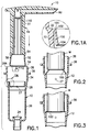
- Fig. 1A is an enlarged fragmentary sectional view of the area of the flap as shown in Fig. 1;
- Figs. 2, 3 and 4 are fragmentary progressive views of the insertion of the tool or mandrel into the body to fold the flap downward;
- Fig. 5 is an enlarged sectional view of an assembled pump dispenser embodying the invention;
- Fig. 5A is an enlarged fragmentary sectional view of a portion of Fig. 5;
- Fig. 6 is a fragmentary sectional view taken on the line 6-6 of Fig. 5; and
- Fig. 7 is a fragmentary exploded view showing the actuator portion of the plunger and the upper part of the body.
-
- A pump dispenser embodying the invention is generally designated 10 in Fig. 5. It comprises a hollow
cylindrical body 12 and a cooperating one-piece plunger 14. Rotatably surrounding the upper end of the body is the threadedclosure 16. - Referring more specifically to the
body 12, it is essentially cup-shaped including a bottom wall 18 which is centrally formed with an inlet opening 20 surrounded by a downward tubular connector 22 receiving a dip tube 21. Above the opening 20 is formed an upward bevelledannular seat 24. Acylindrical side wall 26 extends upward from the perimeter of bottom wall 18 and terminates in acircular mouth 26A. - The sidewall 26 (Fig. 1) extends upward to include a vent opening 27 and a
tapered zone 28 at which the wall flares slightly outward on the inside of the body at surface 30 (Fig. 5) and is thickened as the upper end of thebody 12 is approached. Above thetapered zone 28 the side wall is formed on the inside of the body with an annularradial shoulder 32. From the periphery of the shoulder the side wall extends upward in acylindrical sleeve 34. Outward from a midpoint of the sleeve portion extends an integralannular flange 36, and spaced above the flange the cylindrical sleeve is formed with an outwardperipheral bump 38. - The closure 16 (Fig. 5) is a threaded cap comprising a
sidewall 40 and atop wall 42 which is formed with an aperture 44 to receive thecylindrical sleeve 34 at the upper end of the body. In installation, there is sufficient "give" in thebump 38 and the margin of the aperture 44 to permit thetop wall 42 to snap by the bump so that the cap is entrapped between thebump 38 and theflange 36. - The cap is loosely enough disposed on the
sleeve 34 so that it can spin as it is screwed onto the finish (not shown) of a container. Theflange 36 will, of course, sit on the top of the finish and be sealingly compressed thereagainst when the cap is screwed tight. - The
plunger 14 comprises an elongate tubular piston 50. The piston 50 is defined by astem 51 and an enlargedtubular piston head 52. Intermediate the head and the stem there is formed a narrow annular upwardshoulder 54. The lower end of the head is formed with anannular seal 56 sealingly engaging the inside of theside wall 26 of thebody 12. Inside, above theseal 56, the head presents an annulardownward face 58. - As stated, the
plunger 14 is tubular, formed with an axial passage 64 which may be provided with integralinward ribs 66. - At the upper end of the
plunger 14 and unitary therewith is theactuator 70. Theactuator 70 is formed therein with a check valve cavity 72 (Fig. 5A) at the lower end of which is an inwardannular lip 74. Acentral ball stop 76 extends downward from the actuator head into the upper portion of thecavity 72. A laterally extending portion of theactuator 70 forms the spout 78 (Fig. 5) having adischarge passage 80. - Both the
body 12 and theplunger 14 are molded of a plastic, such as high density polyethylene, which is resilient in thin sections and rigid in thick section. The resilience in thin sections is used to advantage in thepiston seal 56 and in theflap 100 adjacent thesidewall 28, to be explained. - The upper end of the
plunger 14 andsleeve 34 are formed with interfitting lockdown means. This comprises the diametrically opposed outward pins 110 (Fig. 6) on theplunger 14 and thebayonet grooves 112 in the upper end of thepump body 12. As shown in Figs. 6 and 7, the lower locking portion of the grooves is preferably aradial opening 112A. - The valving for the dispenser comprises the
inlet check ball 81 which seats onseat 24 at the lower end of thebody 12, and thedischarge check ball 82 which seats on theinward lips 74 at the upper end of the plunger. In assembly, theball 82 is installed by being forcibly inserted through thelips 74 from below. Aspring 84 is compressively disposed between theannular face 58 and the bottom wall 18 of the body and urges the plunger upward. - The operation of the pump dispenser is as well known in the art exemplified by the Cooprider patent.
- Attention is now directed to the method by which the dispenser of the invention is made. In the molding of the
body 12 an annular inward andupward retaining flap 100 is formed unitary with thebody 12 inward from theannular shoulder 32 and at the lower end of thecylindrical sleeve 34. - As shown in Fig. 1A, the
annular flap 100 is unitary with thebody 12 and as molded extends upward from ajuncture 101 at the inward edge of theshoulder 32 and inclines inwardly at aturn 102. Theflap 100 extends inward from theturn 102 at an angle of approximately 45° to the horizontal to an inwarddistal edge 104. Between thedistal edge 104 and theturn 102 theflap 100 tapers slightly, narrowing toward theturn 102. By having the narrowest width of the flap at theturn 102, the fold of the flap at the turn during the shaping of the pump body is facilitated. - In the preparation of the body 12 (Fig. 2) a tool or mandrel M is inserted into the body. As the lower end of the mandrel M enters the body, it engages the flap 100 (Fig. 3) and deflects the flap to horizontal (Fig. 3). Further insertion of the mandrel bends the flap down (Fig. 4). The shape thus formed is a downward incline of the flap which could not be molded given the closed lower end of the
body 12. - The mandrel M is removed.
- In the assembly of the pump (Fig. 1) the
plunger 14 is inserted into thebody 12. The lower end of thepiston head 52 engages the inner side offlap 100. Further insertion spreads the flap, and as the shoulder 54 (Fig. 1) of the piston passes theflap 100, theflap 100 snaps inwardly toward the side of thestem 51 of the piston. Any attempt at retraction of the plunger for that matter, will be stopped as theshoulder 54 on the piston engages thedistal edge 104 of theflap 100. The flap thus becomes a lock, entrapping the plunger in the body. - The hold-down means shown in Figs. 6 and 7 is engaged by depressing the
plunger 14 while thepins 110 are in line with the vertical portion of thebayonet grooves 112. Thepins 110 bottom out in the bottom of the grooves. The plunger is then turned clockwise to trap thepins 110 in the horizontal runs of thegrooves 112 in line with theradial openings 112A. - The present invention provides a low-cost pump dispenser. An important aspect is the structure and method by which the
plunger 14 is held in thebody 12. This includes theflap 100, and the method of shaping the flap as described is also part of the invention. In contrast to what the art shows, this lock involves no additional parts and no special tools or swaging steps. - Variations in the product and method invention are possible. Thus, while the invention has been shown in only one embodiment and method, it is not so limited but is of a scope defined by the following claim language which may be broadened by an extension of the right to exclude others from making, using or selling the invention as is appropriate under the doctrine of equivalents.
Claims (7)
- A pump dispenser comprising a molded hollow cup-shaped cylindrical body comprising a bottom wall having a central inlet opening and a continuous sidewall terminating upwardly in a circular mouth, the sidewall being integrally formed with an annular retaining flap joining the sidewall at an annular juncture, the flap being inclined inwardly and upwardly and is manipulable about the annular juncture to an inwardly and downwardly inclined position to constitute a retaining flap for blocking removal of a plunger operable in the body.
- A pump dispenser as claimed in Claim 1 wherein at the juncture the flap is reduced in thickness.
- A pump dispenser as claimed in Claim 1 further including a one-piece plunger operable in the body and including a downward piston having an axial passage and defined by a tubular stem engaged by the retaining flap and having a piston head formed on the lower end of the plunger, an actuator formed on the upper end of the plunger, the actuator including a lateral passage connected to the axial passage in the piston, the stem being formed in the axial passage with annular inward lips inclined toward the lower end, the lips extending inward into the axial passage so that they are free to flex, and a ball in the axial passage normally resting on the lips in a position between the lips and the actuator.
- A pump dispenser as claimed in Claim 3 wherein a surface of the lips more proximate the piston head is spaced inward from an adjacent margin of the axial passage.
- A pump dispenser as claimed in Claim 3 wherein the actuator includes a downward tapered ball stop extending into the axial passage and adapted to limit the upward travel of the ball.
- A pump dispenser as claimed in Claim 3 wherein the axial passage is formed with inward longitudinal ribs.
- A method of assembling a pump dispenser comprising:a. providing a hollow cylindrical body molded of resilient material having an open upper end and having integrally formed inside the body adjacent its upper end an annular inwardly and upwardly inclined retaining flap having an annular juncture with the wall, an inner side and a distal inner edge,b. providing a cylindrical tool,c. moving an end of the tool into the body to engage the inner side of the flap and force the inner edge downward to fold the flap downward about the annular juncture,d. providing a tubular plunger having at its lower end an enlarged piston head adapted to sealingly engage the surface of the inside of the body, the plunger having an inward shoulder and an elongated reduced stem above the piston head,e. inserting the plunger, piston head first, into the upper end of the body and engaging the inner side of the retaining flap with the head to spread the distal inner edge of the flap, the distal inner edge of the flap thereafter blocking the piston head from upward removal from the body.
Applications Claiming Priority (2)
| Application Number | Priority Date | Filing Date | Title |
|---|---|---|---|
| US09/079,481 US6053371A (en) | 1998-05-15 | 1998-05-15 | Pump dispenser and method for making same |
| US79481 | 1998-05-15 |
Publications (1)
| Publication Number | Publication Date |
|---|---|
| EP0957036A1 true EP0957036A1 (en) | 1999-11-17 |
Family
ID=22150840
Family Applications (1)
| Application Number | Title | Priority Date | Filing Date |
|---|---|---|---|
| EP99108533A Withdrawn EP0957036A1 (en) | 1998-05-15 | 1999-05-04 | Pump dispenser and method for making same |
Country Status (10)
| Country | Link |
|---|---|
| US (2) | US6053371A (en) |
| EP (1) | EP0957036A1 (en) |
| JP (1) | JP3393086B2 (en) |
| KR (1) | KR19990088135A (en) |
| AR (1) | AR015304A1 (en) |
| AU (1) | AU750049B2 (en) |
| BR (1) | BR9901465A (en) |
| CA (1) | CA2270707C (en) |
| CO (1) | CO4980907A1 (en) |
| ID (1) | ID25952A (en) |
Cited By (5)
| Publication number | Priority date | Publication date | Assignee | Title |
|---|---|---|---|---|
| US6250510B1 (en) | 1998-05-15 | 2001-06-26 | Owens-Illinois Closure Inc. | Pump dispenser and method for making same |
| WO2001087494A1 (en) * | 2000-05-11 | 2001-11-22 | Crown Cork & Seal Technologies Corporation | Dispensing pump |
| FR2815618A1 (en) * | 2000-10-23 | 2002-04-26 | Valois Sa | Spray head comprises pump base in which piston slides when moved by push rod, tube connected to pump enclosing an outlet channel and tube, rod and piston consisting of one-piece molding |
| WO2003066235A1 (en) * | 2002-02-06 | 2003-08-14 | Rexam Dispensing Systems | Pump liquid product dispenser |
| EP2854613A4 (en) * | 2012-05-25 | 2016-01-13 | Sth Dev & Design Ab | Dispenser for a pumpable fluid |
Families Citing this family (30)
| Publication number | Priority date | Publication date | Assignee | Title |
|---|---|---|---|---|
| WO1996022924A1 (en) * | 1995-01-27 | 1996-08-01 | Yoshino Kogyosho Co., Ltd. | Liquid jet pump |
| US6173863B1 (en) * | 1999-08-09 | 2001-01-16 | Owens-Illinois Closure Inc. | Pump dispenser having a plunger seal |
| CA2314600A1 (en) | 1999-08-09 | 2001-02-09 | Owens-Illinois Closure Inc. | Pump dispenser having vertical plunger with molded outlet check seat |
| US6290100B1 (en) * | 2000-06-30 | 2001-09-18 | Canberra Corporation | Concentrate cartridge for a diluting and dispensing container |
| US6832916B2 (en) * | 2000-11-20 | 2004-12-21 | Venture Management Alliance, Llc | Soap dispenser hand wash interval timer |
| US6601735B2 (en) | 2001-01-19 | 2003-08-05 | Valois S.A. | Fluid dispenser device |
| US6592010B2 (en) * | 2001-03-22 | 2003-07-15 | Valois S.A. | Fluid dispenser |
| US6695171B2 (en) | 2002-02-12 | 2004-02-24 | Seaquistperfect Dispensing Foreign, Inc. | Pump dispenser |
| US20040069811A1 (en) * | 2002-10-10 | 2004-04-15 | Valois S.A.S. | Fixing member for fixing a dispensing member to an opening of a reservoir, and a dispenser including such a fixing member |
| FR2865198B1 (en) * | 2004-01-16 | 2006-04-14 | Valois Sas | DEVICE FOR DISPENSING FLUID PRODUCT |
| US7249692B2 (en) | 2004-11-29 | 2007-07-31 | Seaquistperfect Dispensing Foreign, Inc. | Dispenser with lock |
| US20060113329A1 (en) * | 2004-11-29 | 2006-06-01 | Seaquisperfect Dispensing Foreign, Inc. | Dispenser with lock |
| EP2046655A4 (en) * | 2006-07-28 | 2012-05-30 | Idispense Llc | Concentrate cartridge for sport drink |
| US7735688B2 (en) * | 2006-10-10 | 2010-06-15 | Meadwestvaco Calmar, Inc. | Rotating collar and locking and venting closure connector for an air foaming pump dispenser |
| US20090308889A1 (en) * | 2008-06-11 | 2009-12-17 | Frank Lindsay | Container system |
| US8302816B2 (en) * | 2008-10-15 | 2012-11-06 | Sim Jae K | Spray bottle with refill cartridge |
| US8157131B2 (en) * | 2008-10-15 | 2012-04-17 | Sim Jae K | Spray bottle with refill cartridge |
| US8261943B2 (en) * | 2008-10-15 | 2012-09-11 | Sim Jae K | Spray bottle with refill cartridge |
| GB0920768D0 (en) * | 2009-11-26 | 2010-01-13 | Rieke Corp | Dispenser pumps |
| US8430137B2 (en) | 2010-08-24 | 2013-04-30 | Jae K. Sim | Refill cap cartridge |
| JP2015096423A (en) * | 2012-02-27 | 2015-05-21 | 多田 哲也 | Piston cylinder device for spray and spray using the same |
| US10794445B2 (en) | 2018-01-03 | 2020-10-06 | Silgan Dispensing Systems Corporation | Dispensing pump with polymer compression spring assembly |
| US11035429B2 (en) | 2018-01-03 | 2021-06-15 | Silgan Dispensing Systems Corporation | Compression spring assembly and methods of using the same |
| US10473176B2 (en) | 2018-01-03 | 2019-11-12 | Silgan Dispensing Systems Corporation | Compression spring assembly and methods of using the same |
| US10870123B2 (en) | 2018-01-03 | 2020-12-22 | Silgan Dispensing Systems Corporation | Dispensing pump with locking structures and methods of using the same |
| US11236794B2 (en) | 2018-01-03 | 2022-02-01 | Silgan Dispensing Systems Corporation | Dispensing pump with polymer spring, base venting and flow baffle |
| CN109335270B (en) * | 2018-08-27 | 2024-01-12 | 浙江正庄实业有限公司 | Ultraviolet-proof and antistatic emulsion pump and preparation method thereof |
| US10526191B1 (en) | 2018-09-27 | 2020-01-07 | Silgan Dispensing Systems Corporation | Dispensing tap and methods for using the same |
| US11312613B2 (en) | 2018-09-27 | 2022-04-26 | Silgan Dispensing Systems Corporation | Dispensing tap and methods for using the same |
| USD980069S1 (en) | 2020-07-14 | 2023-03-07 | Ball Corporation | Metallic dispensing lid |
Citations (4)
| Publication number | Priority date | Publication date | Assignee | Title |
|---|---|---|---|---|
| US3062416A (en) * | 1958-12-01 | 1962-11-06 | Drackett Co | Liquid dispenser |
| US3248021A (en) * | 1962-11-26 | 1966-04-26 | Calmar Inc | Liquid dispenser |
| US3359917A (en) * | 1966-03-01 | 1967-12-26 | Calmar Inc | Liquid dispenser |
| DE1288917B (en) * | 1963-03-21 | 1969-02-06 | Calmar Inc Industry | Sealing device for manually operated spray and atomizer pumps |
Family Cites Families (16)
| Publication number | Priority date | Publication date | Assignee | Title |
|---|---|---|---|---|
| US2521961A (en) * | 1946-01-28 | 1950-09-12 | Pump It Inc | Catchup dispenser |
| US3044413A (en) * | 1959-09-21 | 1962-07-17 | Drackett Co | Pump pistons |
| US3084873A (en) * | 1960-03-28 | 1963-04-09 | Drackett Co | Liquid dispenser |
| US3064310A (en) * | 1960-04-20 | 1962-11-20 | Drackett Co | Method and apparatus for making plastic articles |
| US3128018A (en) * | 1961-07-07 | 1964-04-07 | Drackett Co | Fluid dispensing pump with sealing means |
| US3191814A (en) * | 1962-01-23 | 1965-06-29 | Drackett Co | Liquid dispenser |
| DE1259203B (en) * | 1963-11-30 | 1968-01-18 | Roder Gottfried | Valve for small pumps made of plastic parts |
| US3361078A (en) * | 1965-12-15 | 1968-01-02 | Diamond Int Corp | Liquid dispenser |
| US3362344A (en) * | 1966-03-01 | 1968-01-09 | Calmar Inc | Liquid dispenser |
| US3458090A (en) * | 1967-12-01 | 1969-07-29 | Cook Chem Co | Fluid dispenser with adjustable stroke pump piston |
| FR1590976A (en) * | 1968-11-08 | 1970-04-20 | ||
| US3759426A (en) * | 1972-09-08 | 1973-09-18 | N Kane | Manually-operated liquid dispenser |
| US4089442A (en) * | 1976-09-30 | 1978-05-16 | Ethyl Corporation | Accumulative pressure pump |
| FR2526403A1 (en) * | 1982-05-10 | 1983-11-10 | Ethyl Prod | HAND-OPERATED PUMP ASSEMBLY |
| US5381932A (en) * | 1992-04-14 | 1995-01-17 | American Wyott Corporation | Condiment pump |
| US6053371A (en) | 1998-05-15 | 2000-04-25 | Owens-Illinois Closure Inc. | Pump dispenser and method for making same |
-
1998
- 1998-05-15 US US09/079,481 patent/US6053371A/en not_active Expired - Lifetime
-
1999
- 1999-05-04 EP EP99108533A patent/EP0957036A1/en not_active Withdrawn
- 1999-05-04 CA CA002270707A patent/CA2270707C/en not_active Expired - Fee Related
- 1999-05-05 AU AU26958/99A patent/AU750049B2/en not_active Ceased
- 1999-05-08 KR KR1019990016436A patent/KR19990088135A/en not_active Application Discontinuation
- 1999-05-11 ID IDP990437D patent/ID25952A/en unknown
- 1999-05-13 AR ARP990102272A patent/AR015304A1/en unknown
- 1999-05-14 BR BR9901465-3A patent/BR9901465A/en not_active IP Right Cessation
- 1999-05-17 JP JP13552999A patent/JP3393086B2/en not_active Expired - Fee Related
- 1999-11-12 CO CO99071664A patent/CO4980907A1/en unknown
-
2000
- 2000-03-13 US US09/525,311 patent/US6250510B1/en not_active Expired - Lifetime
Patent Citations (4)
| Publication number | Priority date | Publication date | Assignee | Title |
|---|---|---|---|---|
| US3062416A (en) * | 1958-12-01 | 1962-11-06 | Drackett Co | Liquid dispenser |
| US3248021A (en) * | 1962-11-26 | 1966-04-26 | Calmar Inc | Liquid dispenser |
| DE1288917B (en) * | 1963-03-21 | 1969-02-06 | Calmar Inc Industry | Sealing device for manually operated spray and atomizer pumps |
| US3359917A (en) * | 1966-03-01 | 1967-12-26 | Calmar Inc | Liquid dispenser |
Cited By (5)
| Publication number | Priority date | Publication date | Assignee | Title |
|---|---|---|---|---|
| US6250510B1 (en) | 1998-05-15 | 2001-06-26 | Owens-Illinois Closure Inc. | Pump dispenser and method for making same |
| WO2001087494A1 (en) * | 2000-05-11 | 2001-11-22 | Crown Cork & Seal Technologies Corporation | Dispensing pump |
| FR2815618A1 (en) * | 2000-10-23 | 2002-04-26 | Valois Sa | Spray head comprises pump base in which piston slides when moved by push rod, tube connected to pump enclosing an outlet channel and tube, rod and piston consisting of one-piece molding |
| WO2003066235A1 (en) * | 2002-02-06 | 2003-08-14 | Rexam Dispensing Systems | Pump liquid product dispenser |
| EP2854613A4 (en) * | 2012-05-25 | 2016-01-13 | Sth Dev & Design Ab | Dispenser for a pumpable fluid |
Also Published As
| Publication number | Publication date |
|---|---|
| AR015304A1 (en) | 2001-04-18 |
| BR9901465A (en) | 2000-02-29 |
| CO4980907A1 (en) | 2000-11-27 |
| US6053371A (en) | 2000-04-25 |
| JP3393086B2 (en) | 2003-04-07 |
| KR19990088135A (en) | 1999-12-27 |
| US6250510B1 (en) | 2001-06-26 |
| CA2270707C (en) | 2005-09-13 |
| CA2270707A1 (en) | 1999-11-15 |
| ID25952A (en) | 2000-11-16 |
| AU2695899A (en) | 1999-11-25 |
| JP2000033299A (en) | 2000-02-02 |
| AU750049B2 (en) | 2002-07-11 |
Similar Documents
| Publication | Publication Date | Title |
|---|---|---|
| US6053371A (en) | Pump dispenser and method for making same | |
| CA1302982C (en) | Dosaging pump with pump bellows on bottles or the like | |
| JPH0335884Y2 (en) | ||
| EP0309001A2 (en) | A sealing assembly and sealing collar for use in a liquid dispensing device | |
| EP2374732B1 (en) | Synthetic resin container provided with an inverting, foldback bottom wall | |
| US5810209A (en) | Dispenser with improved bottle connection | |
| US5222636A (en) | Apparatus for spraying a liquid from a container | |
| US6315162B1 (en) | Pump dispenser having a plunger seal | |
| EP0662350A2 (en) | Trigger sprayer | |
| US4033487A (en) | Double trigger pump | |
| US5794821A (en) | Reciprocating liquid pump with disc check valve for dispensing lotion and the like | |
| WO1998013293A1 (en) | Dispenser with snap-fit container connection | |
| US6234361B1 (en) | Pump dispenser piston provided with a plastic inlet check valve insert | |
| WO2017072506A1 (en) | Dispenser pump | |
| US6817494B2 (en) | Valve assembly for pressurized fluid containers | |
| US4053086A (en) | Pumps for hand-held dispensers | |
| CA2475369A1 (en) | Pump liquid product dispenser | |
| US5108013A (en) | Pump for dispensing liquid from a container | |
| EP1075874A2 (en) | Pump dispenser having vertical plunger with molded outlet check seat | |
| NL8401810A (en) | CONTROL HEAD FOR A DISPENSER. | |
| MXPA99004318A (en) | Pump supplier and method to manufacture of mi | |
| JP3582226B2 (en) | Pump dispenser and ejector head | |
| EP4232208A1 (en) | Aerosol dispensing device and method for manufacturing an aerosol dispensing device | |
| CA3108343A1 (en) | Food product dispenser valve normally biased into closed position | |
| CN1240752A (en) | Pump dispenser and method for making same |
Legal Events
| Date | Code | Title | Description |
|---|---|---|---|
| PUAI | Public reference made under article 153(3) epc to a published international application that has entered the european phase |
Free format text: ORIGINAL CODE: 0009012 |
|
| AK | Designated contracting states |
Kind code of ref document: A1 Designated state(s): AT BE CH DE DK ES FI FR GB GR IE IT LI NL PT SE |
|
| AX | Request for extension of the european patent |
Free format text: AL;LT;LV;MK;RO;SI |
|
| 17P | Request for examination filed |
Effective date: 20000428 |
|
| AKX | Designation fees paid |
Free format text: AT BE CH DE DK ES FI FR GB GR IE IT LI NL PT SE |
|
| 17Q | First examination report despatched |
Effective date: 20020212 |
|
| GRAP | Despatch of communication of intention to grant a patent |
Free format text: ORIGINAL CODE: EPIDOSNIGR1 |
|
| STAA | Information on the status of an ep patent application or granted ep patent |
Free format text: STATUS: THE APPLICATION IS DEEMED TO BE WITHDRAWN |
|
| 18D | Application deemed to be withdrawn |
Effective date: 20050222 |