EP0956965A2 - Ink cartridge for ink-jet printing apparatus - Google Patents
Ink cartridge for ink-jet printing apparatus Download PDFInfo
- Publication number
- EP0956965A2 EP0956965A2 EP99303695A EP99303695A EP0956965A2 EP 0956965 A2 EP0956965 A2 EP 0956965A2 EP 99303695 A EP99303695 A EP 99303695A EP 99303695 A EP99303695 A EP 99303695A EP 0956965 A2 EP0956965 A2 EP 0956965A2
- Authority
- EP
- European Patent Office
- Prior art keywords
- ink
- ink cartridge
- cartridge
- housing
- lid
- Prior art date
- Legal status (The legal status is an assumption and is not a legal conclusion. Google has not performed a legal analysis and makes no representation as to the accuracy of the status listed.)
- Granted
Links
Images


Classifications
-
- B—PERFORMING OPERATIONS; TRANSPORTING
- B41—PRINTING; LINING MACHINES; TYPEWRITERS; STAMPS
- B41J—TYPEWRITERS; SELECTIVE PRINTING MECHANISMS, i.e. MECHANISMS PRINTING OTHERWISE THAN FROM A FORME; CORRECTION OF TYPOGRAPHICAL ERRORS
- B41J2/00—Typewriters or selective printing mechanisms characterised by the printing or marking process for which they are designed
- B41J2/005—Typewriters or selective printing mechanisms characterised by the printing or marking process for which they are designed characterised by bringing liquid or particles selectively into contact with a printing material
- B41J2/01—Ink jet
- B41J2/17—Ink jet characterised by ink handling
- B41J2/175—Ink supply systems ; Circuit parts therefor
- B41J2/17503—Ink cartridges
- B41J2/1752—Mounting within the printer
- B41J2/17523—Ink connection
-
- B—PERFORMING OPERATIONS; TRANSPORTING
- B41—PRINTING; LINING MACHINES; TYPEWRITERS; STAMPS
- B41J—TYPEWRITERS; SELECTIVE PRINTING MECHANISMS, i.e. MECHANISMS PRINTING OTHERWISE THAN FROM A FORME; CORRECTION OF TYPOGRAPHICAL ERRORS
- B41J2/00—Typewriters or selective printing mechanisms characterised by the printing or marking process for which they are designed
- B41J2/005—Typewriters or selective printing mechanisms characterised by the printing or marking process for which they are designed characterised by bringing liquid or particles selectively into contact with a printing material
- B41J2/01—Ink jet
- B41J2/17—Ink jet characterised by ink handling
- B41J2/175—Ink supply systems ; Circuit parts therefor
- B41J2/17503—Ink cartridges
- B41J2/17513—Inner structure
-
- B—PERFORMING OPERATIONS; TRANSPORTING
- B41—PRINTING; LINING MACHINES; TYPEWRITERS; STAMPS
- B41J—TYPEWRITERS; SELECTIVE PRINTING MECHANISMS, i.e. MECHANISMS PRINTING OTHERWISE THAN FROM A FORME; CORRECTION OF TYPOGRAPHICAL ERRORS
- B41J2/00—Typewriters or selective printing mechanisms characterised by the printing or marking process for which they are designed
- B41J2/005—Typewriters or selective printing mechanisms characterised by the printing or marking process for which they are designed characterised by bringing liquid or particles selectively into contact with a printing material
- B41J2/01—Ink jet
- B41J2/17—Ink jet characterised by ink handling
- B41J2/175—Ink supply systems ; Circuit parts therefor
- B41J2/17503—Ink cartridges
- B41J2/1752—Mounting within the printer
-
- B—PERFORMING OPERATIONS; TRANSPORTING
- B41—PRINTING; LINING MACHINES; TYPEWRITERS; STAMPS
- B41J—TYPEWRITERS; SELECTIVE PRINTING MECHANISMS, i.e. MECHANISMS PRINTING OTHERWISE THAN FROM A FORME; CORRECTION OF TYPOGRAPHICAL ERRORS
- B41J2/00—Typewriters or selective printing mechanisms characterised by the printing or marking process for which they are designed
- B41J2/005—Typewriters or selective printing mechanisms characterised by the printing or marking process for which they are designed characterised by bringing liquid or particles selectively into contact with a printing material
- B41J2/01—Ink jet
- B41J2/17—Ink jet characterised by ink handling
- B41J2/175—Ink supply systems ; Circuit parts therefor
- B41J2/17503—Ink cartridges
- B41J2/17533—Storage or packaging of ink cartridges
-
- B—PERFORMING OPERATIONS; TRANSPORTING
- B41—PRINTING; LINING MACHINES; TYPEWRITERS; STAMPS
- B41J—TYPEWRITERS; SELECTIVE PRINTING MECHANISMS, i.e. MECHANISMS PRINTING OTHERWISE THAN FROM A FORME; CORRECTION OF TYPOGRAPHICAL ERRORS
- B41J2/00—Typewriters or selective printing mechanisms characterised by the printing or marking process for which they are designed
- B41J2/005—Typewriters or selective printing mechanisms characterised by the printing or marking process for which they are designed characterised by bringing liquid or particles selectively into contact with a printing material
- B41J2/01—Ink jet
- B41J2/17—Ink jet characterised by ink handling
- B41J2/175—Ink supply systems ; Circuit parts therefor
- B41J2/17503—Ink cartridges
- B41J2/17536—Protection of cartridges or parts thereof, e.g. tape
-
- B—PERFORMING OPERATIONS; TRANSPORTING
- B41—PRINTING; LINING MACHINES; TYPEWRITERS; STAMPS
- B41J—TYPEWRITERS; SELECTIVE PRINTING MECHANISMS, i.e. MECHANISMS PRINTING OTHERWISE THAN FROM A FORME; CORRECTION OF TYPOGRAPHICAL ERRORS
- B41J2/00—Typewriters or selective printing mechanisms characterised by the printing or marking process for which they are designed
- B41J2/005—Typewriters or selective printing mechanisms characterised by the printing or marking process for which they are designed characterised by bringing liquid or particles selectively into contact with a printing material
- B41J2/01—Ink jet
- B41J2/17—Ink jet characterised by ink handling
- B41J2/175—Ink supply systems ; Circuit parts therefor
- B41J2/17503—Ink cartridges
- B41J2/17553—Outer structure
Definitions
- the present invention relates to an ink cartridge detachably mounted on a carriage onto which a print head for ejecting ink droplets is attached.
- a conventional ink cartridge mounted on a carriage onto which a print head for ejecting ink droplets is attached typically includes a container having on one wall thereof an ink supply port where an ink supply needle of a printing apparatus is inserted and an opening on the other wall thereof which is sealed by a lid as disclosed, for example, in Japanese published unexamined patent application No. Hei. 8-132635.
- the container accommodates therein a porous body impregnated with ink and which is formed of polymeric resin.
- a first object of the present invention is to provide an ink cartridge capable of fitting to one or more ink supply needle communicating with a print head only in a proper position with respect to an ink-jet printing apparatus.
- a second object of the present invention is to provide an ink cartridge capable of preventing the ink supply needle of a printing apparatus from being broken due to improper installation of the ink cartridge on the ink-jet printing apparatus.
- an ink cartridge which,according to the present invention, includes an ink container for accommodating ink therein, an ink supply port formed on the ink container for receiving an ink supply needle communicating with a print head attached to the carriage, and one or more recessed part for receiving a projection protruding from the carriage of the printing apparatus, which recessed part being formed in a position to face the projection.
- the projection is formed in the vicinity of the ink supply needle in a state in which when the ink cartridge is installed in a regular, proper direction the projection of the carriage inserts into the recessed part of the ink cartridge.
- the height of the protrusion is designed to be higher than that of the ink supply needle.
- the projection on the carriage first fits into the recessed part of the cartridge, and then the ink supply needle inserts into the ink supply port of the cartridge by further urging the ink cartridge against the carriage.
- the projection first comes into abutment against the bottom of the cartridge, and the cartridge cannot be mounted on the carriage.
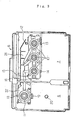
- Fig. 1 shows a printing mechanism equivalent to an embodiment of a printing apparatus for executing printing using an ink cartridge according to the present invention
- a cartridge holder 6 mounting thereon both a black ink cartridge and a color ink cartridge respectively provided with pivotable levers 4 and 5 is secured onto a carriage 3 operatively connecting to a driving motor 2 via a timing belt 1 and a print head 23 to which ink is supplied from each ink cartridge is provided on the lower surface of the carriage.
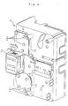
- Figs. 2 and 3 show an embodiment of the cartridge holder 6 mounted on the above carriage and in this embodiment, a color ink cartridge housing chamber 7 and a black ink cartridge housing chamber 8 are formed.
- Ink supply needles 10 and 11 respectively communicating with the print head 23 are planted in respective positions opposite to the respective ink supply ports of the ink cartridges in case each cartridge is normally installed.
- Rectangular recessed sections 21 and 22 are formed so that they respectively surround the periphery of these ink supply needles 10 and 11.
- projections 12, 13, 14, 15 and 16 each tip end of which is slightly higher than that of each ink supply needle 10 are formed approximately along the walls of the recessed part 21 at four corners of an area in which the ink supply needles 10 are arranged so that the bottom of the ink cartridge can be horizontally supported.
- first and second projections 18 and 19 each upper end of which is slightly higher than the end of the ink supply needle 11 are formed so that the ink supply needle 11 is put between the projections and in the center, a third projection 20 is formed.
- the second projection 19 is formed wider to the extent that the bottom of the ink cartridge can be horizontally supported when the ink cartridge is installed in a wrong direction.
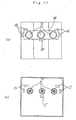
- Figs. 4 and 5 show the structure of the rear side of the cartridge holder, a passage forming part 26 defining the recessed sections 21, 22 and communicating passages 24 and 25 for connecting each of the ink supply needles 10 and 11 and the print head 23 are protruded, the upper surface is sealed by a sealing plate 27, the print head 23 is laminated and fixed on the surface.
- caulking ribs 26a are formed together with the communicating passages by injection molding and others in addition to the communicating passages 24 and 25 as shown in Figs. 5, through holes 28 and 29 respectively connecting to the print head and caulking holes 28a are also formed on the sealing plate 27 and both are fixed in a fluid-tight state by caulking.
- the print head 23 is mounted on the sealing plate in a state in which its ink inlets respectively communicate with the through holes 28 and 29 of the sealing plate.
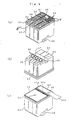
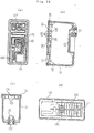
- Figs. 6(a) to 6(c) are perspective views showing an embodiment of a color ink cartridge.
- the color ink cartridge is composed as a container 32 on one side of which ink supply ports 30 where the ink supply needles 10 of the printing apparatus are respectively inserted are formed and the opposite open face of which is sealed by a lid 31, and a porous body impregnated with ink is housed inside the color ink cartridge.
- Ink inlets 33 and air communicating ports 34 are formed on the surface of the lid 31 and each air communicating port 34 is connected to one end of a fine, circuitous groove 36 sealed by a sealing film 35.
- the fine groove 36 generates the capillary action.
- the other end of the fine groove 36 communicates with an air communication opening 39 formed in a recessed part 38.
- the recessed part 38 is formed on the other end of the fine groove 36 through a communicating (or tunnel) passage 37 formed as a through hole and extends approximately horizontally inside the thickness of the lid 31.
- the tunnel passage 37 is designed to incline from the air communication opening 39 formed in the recessed part 38, so that no part of the air communication passage, including fine groove 36, tunnel passage 37 and the recessed part 38 does pass in the interior side of the lid 31 of the ink cartridge.
- the sealing film 35 has a size which is equal to or slightly smaller than an area defined by a rectangular recess 231 formed in the edge of the lid 31, so that the four edges of the sealing film 35 are bent down into the recess. Owing to the design, the sealing film 35 is hardly peeled off when a user touches the ink cartridge when mounted on the printer.
- a recessed part 40 for fitting to the projection of a lever 4 is formed on the center line of the lid 31 and a recessed part 41 for securing negative-pressure volume is formed in a residual part.
- the recessed parts 38 are completely sealed by a film 42 one end 42a of which is extended outside the lid and which can be peeled, and the recessed parts 40 and 41 are partly sealed by the same film 42 in a state in which openings 40a and 41a for communicating with the air are formed respectively in a part.
- Recessed parts 44 to 47 for fitting to projections 12 to 16 on the side of the cartridge holder 6 are formed so that these ink supply ports 30 are put between the diagonal points of an imaginary quadrilateral.
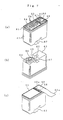
- the black ink cartridge is composed as a container 52 on one side of which an ink supply port 50 where the ink supply needle 10 of the printing apparatus is inserted is formed and the opposite open face of which is sealed by a lid 51 as shown in Figs. 7, and a porous body impregnated with ink is housed inside the black ink cartridge.
- An ink inlet 53 and an air communicating port 54 are formed on the surface of the lid 51 and the air communicating port 54 is connected to one end of a fine groove 56 sealed by a film 55 and forming a capillary.
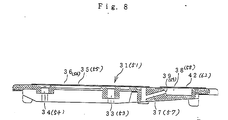
- the other end of the fine groove 56 communicates with an opening 59 provided to a recessed part 58 formed on the side of the other end through a communicating passage 57 formed as a through hole and extended approximately horizontally inside the lid 51 as shown in Fig. 8.
- Each through hole respectively forming the above communicating passages 37 and 57 is tilted so that each side of the recessed parts 38 and 58 is slightly higher so as to enable pulling out a pin in injection molding.
- a recessed part 60 for fitting to the projection of the lever 5 is formed on the center line of the lid 51 and a recessed part 61 for securing negative-pressure volume is formed in a residual part.
- the recessed part 58 is completely sealed by a film 62 one end 62a of which extends beyond an edge of the lid 51 and which can be peeled off when used and the recessed part 60 is partly sealed by the same film 62 in a state in which a part 60a communicates with the air.
- the recessed part 61 communicates with the recessed part 60 via a recessed part 61a.
- a package is supported by the film 42 or 62 by sealing the recessed part 41 or 60 in a state in which it communicates with the air by the film 42 or 62 and space for decompression can be prevented from being blocked by the package.
- a flexible package 180 such as an aluminum layered package or vinyl made package and sealed under vacuum condition as shown in Fig. 31
- air transfer occurs between the ink chamber 137 and the recessed parts 145 formed on the lid of the cartridge. That is, gas contained in ink or gas generated when ink component is dissolved moves into the recessed parts 145. Accordingly, no air bubble would be created in the ink even when the ink cartridge is stocked in a warehouse for a long time.
- a convex portion 67 provided with a shape approximately equivalent to the inner wall of the recessed part 22 of the cartridge holder 6 and slightly protruded from the bottom 63 is formed and the ink supply port 50 for fitting to the ink supply needle 11 is provided to the convex portion 67.
- Recessed parts 64 and 65 for fitting to the projections 18, 19 and 20 on the side of the holder 6 are formed at the front side and the rear side of the ink supply port 50 in such a manner that the ink supply port is located between the recessed parts.
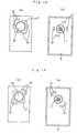
- the air communicating opening 59 becomes open to the air and the recessed part 60 is also exposed. If the black ink cartridge K is installed in a proper direction of the cartridge holder 6, the recessed parts 64 and 65 formed on the bottom 63 are opposed to the projections 18 to 20 of the holder 6 as shown in Fig. 9a.
- the projection 5a of the lever 5 is fitted into the recessed part 60 of the lid 51 and pushes down the cartridge K.
- the projections 18, 19 and 20 of the holder 6 are respectively first fitted into the recessed parts 64 and 65 of the cartridge K and the cartridge K is guided to a normal position by a slant face 18a formed at the end and a tapered part 20a.
- the ink supply needle 11 pierces the film 66 sealing the ink supply port 50 and is inserted into the ink supply port 50 as shown in Fig. 9b, the lever 5 is moved up to a normal position and a fitting part 5b is fixed to a hook 3a of the carriage 3.
- the convex portion 67 in which the ink supply port 50 is formed is fitted into the recessed part 22 of the cartridge holder 6 and caught, the printing apparatus is prevented from rattling due to vibration and others in a state in which the cartridge K is installed in a normal position. and the leakage of ink and the application of unnecessary external force to the ink supply needle are securely prevented.
- the films 35 and 55 forming a capillary together with the fine groove and the films 42 and 62 peeled because of communication with the air in use are respectively independently stuck on the lids 31 and 51, however, even if an integrated film 70 in which an area 70a forming a capillary and an area 70b to be exposed in use are connected via a narrow part 70c which can be torn off as shown in Fig. 11a, and a film 71 forming a capillary and a film 72 to be peeled off overlapping with the film 71 in a part 71a as shown in Fig. 11b are respectively stuck, the similar action is produced. Further, if a second film 71' is stuck as shown in Fig. 11c so that the surface of the lid is at least covered in the area 70a forming a capillary, ink can be securely prevented from being evaporated.
- a first sealing film 76 covers fine, circuitous grooves 34 formed on a lid 31 of the ink cartridge 132 whereas a second sealing film 77 covers entire surface of the lid 31 over the first sealing film 76 not only air communication holes 39.
- the second sealing film 77 may be peeled off when the ink cartridge is in use.
- the first sealing film 76 and the second sealing film 77 may have different colors from each other or formed from different material. This arrangement may be advantageous in that a user can easily recognize that which sealing film is to be peeled off.
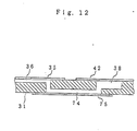
- the communicating passages 37 and 57 are respectively formed as a through hole approximately horizontally extending though it is slightly tilted, however, even if one end of a fine groove 36 composing a capillary pierces a lid 31, a fine, circuitous groove 74 is formed so that the fine groove 36 communicates with a recessed part 38 for opening to the air and the fine groove 74 is covered by a sealing film 75 as shown in Fig. 12, the similar action is produced.
- through holes to be the communicating passages 37 and 57 are formed, work for inserting/extracting a pin required in an injection molding process is not required and a process for forming the lid can be simplified.
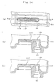
- the recessed part 65 for fitting to the projection 19 is integrated with the recessed part for fitting to the projection 20 to install or detach the cartridge K in or from the carriage or the cartridge holder 6 by a mechanism in which a lifter 176 connects to the lever 105 via an operating rod 175 as shown in Fig. 13.
- the lifter 176 is guided up and down along a guide groove 177 by the operation of the lever 105, so that the ink cartridge is attached to or detached from the cartridge holder 6.
- the projection 19 engages with and disengages from one recessed part 65a of the ink cartridge so that the ink cartridge can be accurately positioned as mentioned above.
- recessed parts 68 are formed along one wall of a convex portion 48 in which the ink supply port 30 is formed and on the side of the cartridge so that as a large interval as possible is left as shown in Figs. 15a and 15b and that a recessed part 69 is formed on the other side across the convex portion 48 so that the recessed part 69 is opposite to the recessed part 68.
- recessed parts 68 and 69 are located at the diagonal points of a convex portion 48 as shown in Fig. 16a and formed so that they are close to the wall of the convex portion 48 in a color ink cartridge, while convex portions 12' and 15' may be also formed in the color ink cartridge housing chamber 7 of the holder 6 so that the convex portions respectively correspond to the recessed parts 68 and 69.
- a recessed part 69' may be also formed in the center of the wall on which no recessed part exists of the convex portion 48 where the ink supply port 30 is formed with the recessed part 69' close to the wall of the convex portion 48 as shown in Fig. 17a.
- a convex portion 12" corresponding to the recessed part 69' is naturally formed corresponding to the above ink cartridge.
- the ink cartridge can be more securely prevented by the convex portions 12', 12" and 15' arranged around the ink supply needle 10 from being improperly inserted.
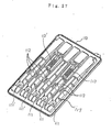
- the above embodiment relates to the color ink cartridge, however, as for a black ink cartridge paired with it, embodiments shown in Figs. 18a to 21b are desirable.
- recessed parts 64 and 65 are located at the diagonal points of a convex portion 67 and formed so that they are close to the wall of the convex portion 67, while convex portions 18' and 19' are formed corresponding to these recessed parts 64 and 65 in the ink cartridge housing chamber 8 of the holder 6 as shown in Fig. 18b, a pair of adjacent recessed parts 64 and a pair of adjacent recessed parts 65 are located at diagonal points as shown in Fig. 19a, while convex portions 18' are formed adjacently and convex portions 19' are formed adjacently respectively corresponding to the recessed parts 64 and 65 as shown in Fig. 19b in the ink cartridge housing chamber 8 of the holder 6.
- recessed parts 64 and 65 may be also formed in the shape of a hook so that they surround the corners of a convex portion 67 and convex portions 18' and 19' may be also formed in the shape of a hook as shown in Fig. 20b.
- recessed parts may be also formed on a center line passing an ink supply port 66 so that they surround the four sides of a convex portion 67 and corresponding to these, convex portions 18' and 19' may be also arranged on a center line passing the ink supply needle 11 in the cartridge housing chamber 8.
- cyan and magenta may be classified into two systems of a dark type and a light type, a color ink cartridge may be divided into five ink housing chambers and each chamber may be filled with ink of cyan, magenta and yellow which belong to the dark type and ink of cyan and magenta which belong to the light type.
- each ink housing chamber 81 to 85 of a cartridge 80 As ink of each color is consumed differently in color printing, the volume of each ink housing chamber 81 to 85 of a cartridge 80 shown in fig. 22a. More specifically, the width w1 to w5 of each housing chamber is designed to be different from one another to fix the ink consumption rate of the whole ink cartridge. In the meantime, each print head to which ink is supplied from each chamber is arranged at fixed pitch in consideration of control and others in printing and therefore, the arrangement pitch of ink supply needles integrated with each print head is also fixed.
- ink supply ports 86 to 90 respectively communicating with the ink housing chambers 81 to 85 of the ink cartridge 80 are formed on the center line c1 to c5 of each chamber, there arises a problem that mis-position is caused between each ink supply needle and each ink supply port of the cartridge, the ink cartridge cannot be installed and the ink supply needle is broken.
- Fig. 22a shows an embodiment of an ink cartridge to solve these problems and although ink output ports 86 to 90 of ink housing chambers 81 to 85 are arranged on each center line c1 to c5 of the ink housing chambers 81 to 85, ink supply ports 91 to 95 are arranged according to the arrangement pitch S of ink supply needles, and the ink output ports and the ink supply ports are respectively connected via passages 96 to 100 in the shape of a crank.
- the ink consumption rate of each ink housing chamber of the cartridge can be adjusted so that it is approximately equal and in addition, fitting to or detaching from the ink supply needle can be smoothly executed.
- an ink consumption rate in the ink cartridge is approximately equalized, however, if an ink consumption rate may be uneven, ink supply ports 91 to 95 are arranged according to the arrangement pitch S of ink supply needles and ink housing chambers 81' to 85' are formed so that each center is located on each center line of the ink supply ports 91 to 95, while a gap made between the cartridge and the cartridge holder 6 may be also adjusted by projections 101 and 102 provided on the side (Fig. 22(b)) and may be also adjusted by adjusting the thickness d of at least one side wall 103 of the ink cartridge (Fig. 22(c)).
- each ink housing chamber 81 to 85 is narrow as described above, the discharge of ink from a porous body impregnated with ink and housed in each ink housing chamber 81 to 85 to each ink supply port 91 to 95 is difficult, compared with an ink cartridge provided with wide ink housing chambers.
- a slant part 106 wider on the side of the ink housing chamber from the side of the ink supply port 93 is formed in a protruding part 105 which protrudes toward the ink housing chamber 83 and on which a filter 104 is stuck as shown in Fig. 23(b).
- the slant part 106 may be arcuatd if desired, so that air bubbles may be guided more effectively to the ink supply port.
- the filter 104 can be prevented from being bent by the pressure of a porous body housed in the ink housing chamber 83 and ink can be made to flow smoothly to the ink supply port 92 by the capillary force of a fine groove generated by the convex portion 108.
- a porous body 109 impregnated with ink as shown in Fig. 25a is originally filled in each ink housing chamber 81 to 85 (the ink housing chamber 82 is represented in Fig. 25a) of such an ink cartridge so that the porous body is touched to the filter 104 as shown in Fig. 25b and is sealed by a lid 110.
- Figs. 26 and 27 are views showing an embodiment of a cartridge lid designed in view of the foregoing problems, and air communicating ports 111 and 111' ink inlets 112 and fine grooves 113 each one end of which communicates with each air communicating port 111 and 111' are formed so that they communicate with each ink housing chamber.
- vertical ribs 117 are formed in the inner face of the lid 110. The both the ends of the vertical ribs 117 perform to guide the cartridge lid 110 into the cartridge body when the lid 110 is coupled to the cartridge body. Because an upper-outer corner of the vertical rib 117 is chamfered to have an angled surface the lid 110 can smoothly be coupled to the cartridge body while guided by the angled surface of the rib 117.
- the fine groove 113 is formed in an area opposite to each ink housing chamber where no air communicating port 111 or 111' and no ink inlet 112 in the above capillary forming area exist so that the fine groove meanders plural times and the fine grooves respectively communicate with openings for communicating with the air 114 and 114' via communicating areas 113 and 113' having the similar structure to the communicating passages 74 shown in Fig. 12.
- an area F in which the fine grooves 113 and 113' are formed is sealed by a film which cannot be peeled off by a user and an area G of the openings for communicating with the air 114 and 114' is sealed by a film which can be peeled by a user.
- Plural recessed parts 115 for securing volume are formed on the side on which the openings for communicating with the air 114 and 114' are formed and if necessary, a recessed part 116 for fitting to the projection 5a shown in Fig. 9 of the lever 5 is also formed.
- a porous body 121 impregnated with ink is housed in an ink housing chamber 120 as shown in Fig. 28b so that the porous body is touched to a filter 123 of an ink supply port 122.
- slight space 126 is secured by a rib 125 on the rear of a cap 124 to prevent ink from leaking due to the rapid change of temperature.
- the above rib 125 is formed so that the rib is opposite to a fine groove 129 connecting an air communicating port 127 and an opening open to the air 128 respectively of the lid 124.
- a reference number 131 denotes a recessed part for fitting to the projection 5a shown in Fig. 9 of the lever 5.
- a porous body impregnated with ink is housed in the whole ink housing chamber, however, even if the present invention is applied to an ink cartridge wherein one ink housing chamber is divided into two chambers 134 and 135 by a partition 133 at the bottom of which a communicating port 132 is provided as shown in Fig. 29, a porous body 137 impregnated with ink is housed on the side of an ink supply port 136 and ink 138 is housed in the other chamber 135, the similar action is produced.
- the fine, circuitous groove creating a capillary action connects to the opening for communicating with the air via the tunnel-like communicating passage formed on the lid however, even if fine grooves 141 respectively connected to air communicating ports 140 of plural ink housing chambers are made to meander so that the fine groove is opposite to the above ink chamber in a central area in which the air communicating ports 140 and ink inlets 142 are formed, are collected with each independent on the side of the other end and are respectively connected to openings for communicating with the air 144 sealed by a film which can be peeled in a very narrow area 143, recessed parts 145 for securing decompression space can be formed in relatively large size as shown in Fig. 30.
Abstract
Description
- The present invention relates to an ink cartridge detachably mounted on a carriage onto which a print head for ejecting ink droplets is attached.
- A conventional ink cartridge mounted on a carriage onto which a print head for ejecting ink droplets is attached typically includes a container having on one wall thereof an ink supply port where an ink supply needle of a printing apparatus is inserted and an opening on the other wall thereof which is sealed by a lid as disclosed, for example, in Japanese published unexamined patent application No. Hei. 8-132635. The container accommodates therein a porous body impregnated with ink and which is formed of polymeric resin.
- In the meantime, for an ink cartridge installed in a printing apparatus wherein color printing is enabled, the same container is divided into plural chambers by one or more partition, a porous body impregnated with ink is housed in each chamber while an ink supply port is formed in each chamber. To mount the ink cartridge provided with plural ink supply ports as described above on a carriage on which ink supply needles of the same number are secured, as a film for sealing openings of the plural ink supply ports is required to be pierced by each ink supply needle, large urging force is required for a user when mounting. Therefore, there has been proposed a printing device designed to have a pivotable lever one end of which is attached to the carriage, so that the ink cartridge can readily be mounted on the carriage by simply operating the lever.
- However, although a cartridge can be mounted with small urging force, misposition of the cartridge with respect to the carriage may occur by rough insertion. Further, as the bottom of the cartridge is pushed with large force in a state in which the bottom comes into engagement with ink supply needles in a case where the cartridge is mounted in a wrong direction, there arises a problem that the ink supply needles are broken.
- Therefore, in view of the foregoing problems accompanying the conventional ink cartridge, a first object of the present invention is to provide an ink cartridge capable of fitting to one or more ink supply needle communicating with a print head only in a proper position with respect to an ink-jet printing apparatus.
- A second object of the present invention is to provide an ink cartridge capable of preventing the ink supply needle of a printing apparatus from being broken due to improper installation of the ink cartridge on the ink-jet printing apparatus.
- The above and other objects can be achieved by a provision of an ink cartridge which,according to the present invention, includes an ink container for accommodating ink therein, an ink supply port formed on the ink container for receiving an ink supply needle communicating with a print head attached to the carriage, and one or more recessed part for receiving a projection protruding from the carriage of the printing apparatus, which recessed part being formed in a position to face the projection. The projection is formed in the vicinity of the ink supply needle in a state in which when the ink cartridge is installed in a regular, proper direction the projection of the carriage inserts into the recessed part of the ink cartridge. The height of the protrusion is designed to be higher than that of the ink supply needle.
- When the ink cartridge is properly mounted on the carriage of the printing apparatus, the projection on the carriage first fits into the recessed part of the cartridge, and then the ink supply needle inserts into the ink supply port of the cartridge by further urging the ink cartridge against the carriage. On the other hand, however, if the ink cartridge is mounted in an improper direction, the projection first comes into abutment against the bottom of the cartridge, and the cartridge cannot be mounted on the carriage.
-
- Fig. 1 is a schematic perspective view showing an ink-jet type printing apparatus;
- Fig. 2 is a perspective enlarged view of a carriage and a cartridge holder mounting thereon an ink cartridge according to the present invention;
- Fig. 3 is a top view of the carriage and the cartridge holder shown in Fig. 2;
- Fig. 4 is a perspective view showing the structure of the rear side of the above cartridge holder shown in Figs. 2 and 3;
- Fig. 5a is a top view showing the cartridge holder in a state where a print head and a sealing plate are detached therefrom;
- Fig. 5b is a top view showing the sealing plate;
- Figs. 6a to 6c are perspective views of an ink cartridge according to one embodiment of the present invention respectively showing the structure of the upper surface of a lid in a state in which a film is detached, the structure on the side of an ink supply port and the structure of the upper surface of the lid in a state in which the film is stuck respectively in an embodiment of a color ink cartridge;
- Figs. 7a to 7c are perspective views of an ink cartridge according to another embodiment of the present invention respectively showing the structure of the upper surface of a lid in a state in which a film is detached, the structure on the side of an ink supply port and the structure of the upper surface of the lid in a state in which the film is stuck respectively in an embodiment of a black ink cartridge;
- Fig. 8 is a side sectional view showing the sectional structure of the respective lids of the color ink cartridge and the black ink cartridge;
- Figs. 9a and 9b are side sectional views of the cartridge holder with the ink cartridge respectively showing a state when the ink cartridge is installed and a state in which it is installed in a proper position respectively of a process for inserting the above black ink cartridge;
- Figs. 10a and 10b are side sectional views of the cartridge holder with the ink cartridge respectively showing a state in case the ink cartridge is installed with the film of the ink cartridge not peeled off and a state in case it is installed in a reverse direction respectively of a process for inserting the above black ink cartridge;
- Figs. 11a to 11c show other methods of sticking a sealing film for sealing the lid according to the present invention;
- Fig. 12 is a sectional view showing another embodiment of a communicating passage formed inside the lid according to the present invention;
- Figs. 13 is a side sectional view showing another embodiment of a mechanism for installing an ink cartridge;
- Figs. 14a and 14b are respectively a perspective view and a top view showing another embodiment of the ink cartridge;
- Figs. 15a and 15b are respectively a perspective view and a bottom view showing further another embodiment of the ink cartridge;
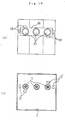
- Figs. 16a and 16b are respectively top views showing structure in which recessed parts are arranged and top views showing the structure of a convex part in the vicinity of an ink supply needle and corresponding to the recessed parts respectively in another embodiment of the color ink cartridge according to the present invention;
- Figs. 17a and 17b are respectively top views showing structure in which recessed parts are arranged and top views showing the structure of a convex part in the vicinity of an ink supply needle and corresponding to the recessed parts respectively in another embodiment of the color ink cartridge according to the present invention;
- Figs. 18a and 18b, Figs. 19a and 19b, Figs. 20a and 20b, and Figs. 21a and 21b are respectively top views showing structure in which recessed parts are arranged and top views showing the structure of a convex part in the vicinity of an ink supply needle and corresponding to the recessed parts respectively in still other embodiments of the black ink cartridge according to the present invention;
- Figs. 22a to 22c are side sectional view showing the other embodiment of the ink cartridge;
- Figs. 23a and 23b are respectively a top view showing a state in which a lid is detached in the other embodiment of the ink cartridge and a side sectional view viewed along a line A-A;
- Figs. 24a to 24c are respectively a top view showing an enlarged vicinity of an ink supply port in the other embodiment of the ink cartridge and sectional views viewed along lines B-B and C-C;
- Fig. 25a is a side sectional view showing a state in which one ink housing chamber of the above ink cartridge is filled with ink, and Fig. 25b is a front sectional view showing the ink cartridge cut along a line E-E in Fig. 25a;
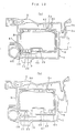
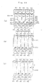
- Fig. 26 is a top view showing the structure of a lid suitable for the ink cartridge shown in Figs. 25a and 25b in a state in which a film is peeled;
- Fig. 27 is a perspective view showing a rear side of the lid shown in Fig. 26;
- Figs. 28a to 28d respectively show the structure of the upper surface of the ink cartridge, sectional structure viewed along lines A-A and B-B and the structure of the rear of the lid;
- Fig. 29 is a sectional view showing the structure of anther type of ink cartridge to which the present invention can be applied;
- Fig. 30 shows another embodiment of fine grooves formed on a lid;
- Fig. 31 is a side sectional view showing an ink cartridge which is packed under a vacuum condition; and
- Fig. 32 is a perspective view showing an ink cartridge and a two separate sealing films according to an arrangement of the invention.
-
- The detailed description of the preferred embodiments of the present invention will now be described hereinbelow with reference to the accompanying drawings.
- Fig. 1 shows a printing mechanism equivalent to an embodiment of a printing apparatus for executing printing using an ink cartridge according to the present invention, a
cartridge holder 6 mounting thereon both a black ink cartridge and a color ink cartridge respectively provided withpivotable levers carriage 3 operatively connecting to a drivingmotor 2 via atiming belt 1 and aprint head 23 to which ink is supplied from each ink cartridge is provided on the lower surface of the carriage. - Figs. 2 and 3 show an embodiment of the
cartridge holder 6 mounted on the above carriage and in this embodiment, a color inkcartridge housing chamber 7 and a black inkcartridge housing chamber 8 are formed. Ink supply needles 10 and 11 respectively communicating with theprint head 23 are planted in respective positions opposite to the respective ink supply ports of the ink cartridges in case each cartridge is normally installed. - Rectangular recessed
sections projections ink supply needle 10 are formed approximately along the walls of the recessedpart 21 at four corners of an area in which the ink supply needles 10 are arranged so that the bottom of the ink cartridge can be horizontally supported. - In the meantime, in the vicinity of the
ink supply needle 11, first andsecond projections ink supply needle 11 are formed so that theink supply needle 11 is put between the projections and in the center, athird projection 20 is formed. Thesecond projection 19 is formed wider to the extent that the bottom of the ink cartridge can be horizontally supported when the ink cartridge is installed in a wrong direction. - Figs. 4 and 5 show the structure of the rear side of the cartridge holder, a
passage forming part 26 defining the recessedsections passages print head 23 are protruded, the upper surface is sealed by a sealingplate 27, theprint head 23 is laminated and fixed on the surface. - In the
passage forming part 26,caulking ribs 26a are formed together with the communicating passages by injection molding and others in addition to the communicatingpassages holes caulking holes 28a are also formed on the sealingplate 27 and both are fixed in a fluid-tight state by caulking. Theprint head 23 is mounted on the sealing plate in a state in which its ink inlets respectively communicate with the throughholes - Figs. 6(a) to 6(c) are perspective views showing an embodiment of a color ink cartridge. The color ink cartridge is composed as a
container 32 on one side of whichink supply ports 30 where the ink supply needles 10 of the printing apparatus are respectively inserted are formed and the opposite open face of which is sealed by alid 31, and a porous body impregnated with ink is housed inside the color ink cartridge. -
Ink inlets 33 andair communicating ports 34 are formed on the surface of thelid 31 and eachair communicating port 34 is connected to one end of a fine,circuitous groove 36 sealed by a sealingfilm 35. Thefine groove 36 generates the capillary action. The other end of thefine groove 36 communicates with anair communication opening 39 formed in a recessedpart 38. As shown in Fig. 8, the recessedpart 38 is formed on the other end of thefine groove 36 through a communicating (or tunnel)passage 37 formed as a through hole and extends approximately horizontally inside the thickness of thelid 31. According to an arrangement, thetunnel passage 37 is designed to incline from theair communication opening 39 formed in the recessedpart 38, so that no part of the air communication passage, includingfine groove 36,tunnel passage 37 and the recessedpart 38 does pass in the interior side of thelid 31 of the ink cartridge. - As shown in Fig. 6(c), the sealing
film 35 has a size which is equal to or slightly smaller than an area defined by arectangular recess 231 formed in the edge of thelid 31, so that the four edges of the sealingfilm 35 are bent down into the recess. Owing to the design, the sealingfilm 35 is hardly peeled off when a user touches the ink cartridge when mounted on the printer. - A recessed
part 40 for fitting to the projection of alever 4 is formed on the center line of thelid 31 and a recessedpart 41 for securing negative-pressure volume is formed in a residual part. The recessedparts 38 are completely sealed by afilm 42 one end 42a of which is extended outside the lid and which can be peeled, and the recessedparts same film 42 in a state in which openings 40a and 41a for communicating with the air are formed respectively in a part. - In the meantime, a
convex portion 48 touched to the inner wall of the recessedpart 21 of thecartridge holder 6, provided with a shape in which the convex portion can insert and slightly protrudes from the bottom 43 is formed and theink supply ports 30 for respectively fitting to the ink supply needles 10 are provided to theconvex portion 48. Recessedparts 44 to 47 for fitting toprojections 12 to 16 on the side of thecartridge holder 6 are formed so that theseink supply ports 30 are put between the diagonal points of an imaginary quadrilateral. - The black ink cartridge is composed as a
container 52 on one side of which anink supply port 50 where theink supply needle 10 of the printing apparatus is inserted is formed and the opposite open face of which is sealed by alid 51 as shown in Figs. 7, and a porous body impregnated with ink is housed inside the black ink cartridge. - An
ink inlet 53 and anair communicating port 54 are formed on the surface of thelid 51 and theair communicating port 54 is connected to one end of afine groove 56 sealed by afilm 55 and forming a capillary. The other end of thefine groove 56 communicates with an opening 59 provided to a recessedpart 58 formed on the side of the other end through a communicatingpassage 57 formed as a through hole and extended approximately horizontally inside thelid 51 as shown in Fig. 8. Each through hole respectively forming the above communicatingpassages parts - A recessed
part 60 for fitting to the projection of thelever 5 is formed on the center line of thelid 51 and a recessed part 61 for securing negative-pressure volume is formed in a residual part. - The recessed
part 58 is completely sealed by afilm 62 one end 62a of which extends beyond an edge of thelid 51 and which can be peeled off when used and the recessedpart 60 is partly sealed by thesame film 62 in a state in which a part 60a communicates with the air. The recessed part 61 communicates with the recessedpart 60 via a recessedpart 61a. - As described above, even if the ink cartridge is packed and vacuumed, a package is supported by the
film part film ink chamber 137 and the recessedparts 145 formed on the lid of the cartridge. That is, gas contained in ink or gas generated when ink component is dissolved moves into the recessedparts 145. Accordingly, no air bubble would be created in the ink even when the ink cartridge is stocked in a warehouse for a long time. - In the meantime, on the rear opposite to the
lid 51, aconvex portion 67 provided with a shape approximately equivalent to the inner wall of the recessedpart 22 of thecartridge holder 6 and slightly protruded from the bottom 63 is formed and theink supply port 50 for fitting to theink supply needle 11 is provided to theconvex portion 67. Recessedparts projections holder 6 are formed at the front side and the rear side of theink supply port 50 in such a manner that the ink supply port is located between the recessed parts. - Next, a process for inserting the ink cartridge composed as described above will be described by the example of the black ink cartridge to simplify the description.
- When an ink cartridge K is taken out of a package which maintains the cartridge under negative pressure in the process of distribution and the
film 62 which can be peeled off is removed, the air communicating opening 59 becomes open to the air and the recessedpart 60 is also exposed. If the black ink cartridge K is installed in a proper direction of thecartridge holder 6, the recessedparts projections 18 to 20 of theholder 6 as shown in Fig. 9a. - When the
lever 5 attached to theholder 6 is operated in this state, the projection 5a of thelever 5 is fitted into the recessedpart 60 of thelid 51 and pushes down the cartridge K. In the process of push down, theprojections holder 6 are respectively first fitted into the recessedparts - When the cartridge K is further pushed down, the
ink supply needle 11 pierces thefilm 66 sealing theink supply port 50 and is inserted into theink supply port 50 as shown in Fig. 9b, thelever 5 is moved up to a normal position and a fitting part 5b is fixed to a hook 3a of thecarriage 3. As theconvex portion 67 in which theink supply port 50 is formed is fitted into the recessedpart 22 of thecartridge holder 6 and caught, the printing apparatus is prevented from rattling due to vibration and others in a state in which the cartridge K is installed in a normal position. and the leakage of ink and the application of unnecessary external force to the ink supply needle are securely prevented. - As the projection 5a of the
lever 5 comes into abutment against thefilm 62 and lifted as shown in Fig. 10a even if the ink cartridge K is installed in a proper posture in case thefilm 62 to be peeled off is left, the fitting part 5b does not reach the hook 3a of thecarriage 3 and thelever 5 cannot be fixed to thecarriage 3. If a user notices it, he or she peels off theleft film 62 and installs the ink cartridge K again. Therefore, a failure of ink supply during printing caused because a user forgets peeling thefilm 62 can be prevented beforehand. - In the meantime, if the black ink cartridge K is installed in the improper way round as shown in Fig. 10b, the bottom 63 is opposed to the
wide projection 19 and is supported in a position higher than the end of theink supply needle 11 in an approximately horizontal posture. As the ink cartridge K does not lower due to theprojection 19 even if thelever 5 is turned in this state, theink supply needle 11 is prevented from being broken. In the case of the color ink cartridge, printing in a state in which thefilm 42 is not peeled is also prevented by the similar action and if the color ink cartridge is installed in a wrong direction, the breakage of theink supply needle 10 is prevented because theprojection 12 comes first into abutment against the bottom 43 and prevents the bottom from lowering. - In the above embodiments, the
films films lids integrated film 70 in which an area 70a forming a capillary and an area 70b to be exposed in use are connected via a narrow part 70c which can be torn off as shown in Fig. 11a, and afilm 71 forming a capillary and afilm 72 to be peeled off overlapping with thefilm 71 in a part 71a as shown in Fig. 11b are respectively stuck, the similar action is produced. Further, if a second film 71' is stuck as shown in Fig. 11c so that the surface of the lid is at least covered in the area 70a forming a capillary, ink can be securely prevented from being evaporated. - According to another arrangement of the invention, as shown in Fig. 32, a
first sealing film 76 covers fine,circuitous grooves 34 formed on alid 31 of theink cartridge 132 whereas a second sealing film 77 covers entire surface of thelid 31 over thefirst sealing film 76 not only air communication holes 39. The second sealing film 77 may be peeled off when the ink cartridge is in use. Thefirst sealing film 76 and the second sealing film 77 may have different colors from each other or formed from different material. This arrangement may be advantageous in that a user can easily recognize that which sealing film is to be peeled off. - Also, in the above embodiments, the communicating
passages fine groove 36 composing a capillary pierces alid 31, a fine,circuitous groove 74 is formed so that thefine groove 36 communicates with a recessedpart 38 for opening to the air and thefine groove 74 is covered by a sealingfilm 75 as shown in Fig. 12, the similar action is produced. According to this embodiment, when through holes to be the communicatingpassages - In the above embodiments, the recessed
part 65 for fitting to theprojection 19 is integrated with the recessed part for fitting to theprojection 20 to install or detach the cartridge K in or from the carriage or thecartridge holder 6 by a mechanism in which alifter 176 connects to thelever 105 via anoperating rod 175 as shown in Fig. 13. In the present embodiment, as shown in Fig. 13, thelifter 176 is guided up and down along aguide groove 177 by the operation of thelever 105, so that the ink cartridge is attached to or detached from thecartridge holder 6. In the operation, theprojection 19 engages with and disengages from one recessedpart 65a of the ink cartridge so that the ink cartridge can be accurately positioned as mentioned above. However, in the case of an ink cartridge mounted or detached by a lever not provided with thelifter 176, even if recessedparts convex portion 67 in which theink supply port 50 is formed is located between the recessedparts part 73 is independently formed in a position opposite to theconvex portion 20 of the cartridge holder, the similar action is produced. - With respect to a color ink cartridge paired with such a black ink cartridge, it is desirable that recessed
parts 68 are formed along one wall of aconvex portion 48 in which theink supply port 30 is formed and on the side of the cartridge so that as a large interval as possible is left as shown in Figs. 15a and 15b and that a recessedpart 69 is formed on the other side across theconvex portion 48 so that the recessedpart 69 is opposite to the recessedpart 68. - As described above, if relationship between another member and the recessed part is not required to be considered, recessed
parts convex portion 48 as shown in Fig. 16a and formed so that they are close to the wall of theconvex portion 48 in a color ink cartridge, while convex portions 12' and 15' may be also formed in the color inkcartridge housing chamber 7 of theholder 6 so that the convex portions respectively correspond to the recessedparts convex portion 48 where theink supply port 30 is formed with the recessed part 69' close to the wall of theconvex portion 48 as shown in Fig. 17a. - A
convex portion 12" corresponding to the recessed part 69' is naturally formed corresponding to the above ink cartridge. Hereby, the ink cartridge can be more securely prevented by theconvex portions 12', 12" and 15' arranged around theink supply needle 10 from being improperly inserted. - The above embodiment relates to the color ink cartridge, however, as for a black ink cartridge paired with it, embodiments shown in Figs. 18a to 21b are desirable.
- That is, in an embodiment shown in Fig. 18a, recessed
parts convex portion 67 and formed so that they are close to the wall of theconvex portion 67, while convex portions 18' and 19' are formed corresponding to these recessedparts cartridge housing chamber 8 of theholder 6 as shown in Fig. 18b, a pair of adjacent recessedparts 64 and a pair of adjacent recessedparts 65 are located at diagonal points as shown in Fig. 19a, while convex portions 18' are formed adjacently and convex portions 19' are formed adjacently respectively corresponding to the recessedparts cartridge housing chamber 8 of theholder 6. Further, as shown in Fig. 20a, recessedparts convex portion 67 and convex portions 18' and 19' may be also formed in the shape of a hook as shown in Fig. 20b. - Further, as shown in Fig. 21a, recessed parts may be also formed on a center line passing an
ink supply port 66 so that they surround the four sides of aconvex portion 67 and corresponding to these, convex portions 18' and 19' may be also arranged on a center line passing theink supply needle 11 in thecartridge housing chamber 8. - Three colors of ink of at least cyan, magenta and yellow and four colors of ink including black if necessary are normally used for color printing, however, to improve the printing quality, cyan and magenta may be classified into two systems of a dark type and a light type, a color ink cartridge may be divided into five ink housing chambers and each chamber may be filled with ink of cyan, magenta and yellow which belong to the dark type and ink of cyan and magenta which belong to the light type.
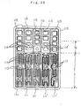
- As ink of each color is consumed differently in color printing, the volume of each
ink housing chamber 81 to 85 of acartridge 80 shown in fig. 22a. More specifically, the width w1 to w5 of each housing chamber is designed to be different from one another to fix the ink consumption rate of the whole ink cartridge. In the meantime, each print head to which ink is supplied from each chamber is arranged at fixed pitch in consideration of control and others in printing and therefore, the arrangement pitch of ink supply needles integrated with each print head is also fixed. - Therefore, if ink supply ports 86 to 90 respectively communicating with the
ink housing chambers 81 to 85 of theink cartridge 80 are formed on the center line c1 to c5 of each chamber, there arises a problem that mis-position is caused between each ink supply needle and each ink supply port of the cartridge, the ink cartridge cannot be installed and the ink supply needle is broken. - Fig. 22a shows an embodiment of an ink cartridge to solve these problems and although ink output ports 86 to 90 of
ink housing chambers 81 to 85 are arranged on each center line c1 to c5 of theink housing chambers 81 to 85,ink supply ports 91 to 95 are arranged according to the arrangement pitch S of ink supply needles, and the ink output ports and the ink supply ports are respectively connected via passages 96 to 100 in the shape of a crank. According to this embodiment, the ink consumption rate of each ink housing chamber of the cartridge can be adjusted so that it is approximately equal and in addition, fitting to or detaching from the ink supply needle can be smoothly executed. - In the above embodiment, an ink consumption rate in the ink cartridge is approximately equalized, however, if an ink consumption rate may be uneven,
ink supply ports 91 to 95 are arranged according to the arrangement pitch S of ink supply needles and ink housing chambers 81' to 85' are formed so that each center is located on each center line of theink supply ports 91 to 95, while a gap made between the cartridge and thecartridge holder 6 may be also adjusted byprojections - If each
ink housing chamber 81 to 85 is narrow as described above, the discharge of ink from a porous body impregnated with ink and housed in eachink housing chamber 81 to 85 to eachink supply port 91 to 95 is difficult, compared with an ink cartridge provided with wide ink housing chambers. - To solve the above problems, it is desirable that a
slant part 106 wider on the side of the ink housing chamber from the side of theink supply port 93 is formed in aprotruding part 105 which protrudes toward theink housing chamber 83 and on which afilter 104 is stuck as shown in Fig. 23(b). Theslant part 106 may be arcuatd if desired, so that air bubbles may be guided more effectively to the ink supply port. - Further, when an elongated
convex portion 108 is formed on a recessedpart 107 formed between the protruding part and thefilter 104 as shown in Figs. 24 in case the protrudingpart 105 is relatively narrow as shown in Fig. 3, thefilter 104 can be prevented from being bent by the pressure of a porous body housed in theink housing chamber 83 and ink can be made to flow smoothly to theink supply port 92 by the capillary force of a fine groove generated by theconvex portion 108. - A
porous body 109 impregnated with ink as shown in Fig. 25a is originally filled in eachink housing chamber 81 to 85 (theink housing chamber 82 is represented in Fig. 25a) of such an ink cartridge so that the porous body is touched to thefilter 104 as shown in Fig. 25b and is sealed by alid 110. - In the
ink cartridge 80 in which multiple ink housing chambers are formed as described above, it is difficult to form a fine, circuitous groove to function as a capillary having large fluid resistance on thelid 110. That is, to increase fluid resistance, the cross section of the fine groove has only to be reduced, however, there is a problem that clogging is caused by dust and others and ink is not supplied in printing. Therefore, as the cross section to some extent is required, fluid resistance is required to be secured by the length of the fine groove. - Figs. 26 and 27 are views showing an embodiment of a cartridge lid designed in view of the foregoing problems, and
air communicating ports 111 and 111'ink inlets 112 andfine grooves 113 each one end of which communicates with eachair communicating port 111 and 111' are formed so that they communicate with each ink housing chamber. As shown in Fig. 27,vertical ribs 117 are formed in the inner face of thelid 110. The both the ends of thevertical ribs 117 perform to guide thecartridge lid 110 into the cartridge body when thelid 110 is coupled to the cartridge body. Because an upper-outer corner of thevertical rib 117 is chamfered to have an angled surface thelid 110 can smoothly be coupled to the cartridge body while guided by the angled surface of therib 117. - The
fine groove 113 is formed in an area opposite to each ink housing chamber where noair communicating port 111 or 111' and noink inlet 112 in the above capillary forming area exist so that the fine groove meanders plural times and the fine grooves respectively communicate with openings for communicating with theair 114 and 114' via communicatingareas 113 and 113' having the similar structure to the communicatingpassages 74 shown in Fig. 12. - As clear from the above description, an area F in which the
fine grooves 113 and 113' are formed is sealed by a film which cannot be peeled off by a user and an area G of the openings for communicating with theair 114 and 114' is sealed by a film which can be peeled by a user. Plural recessedparts 115 for securing volume are formed on the side on which the openings for communicating with theair 114 and 114' are formed and if necessary, a recessedpart 116 for fitting to the projection 5a shown in Fig. 9 of thelever 5 is also formed. - If the lid is formed by injection molding, a so-called shrink is easily caused in an area where the fine groove is formed. In the meantime, as for the ink cartridge, a
porous body 121 impregnated with ink is housed in anink housing chamber 120 as shown in Fig. 28b so that the porous body is touched to afilter 123 of anink supply port 122. In this case,slight space 126 is secured by arib 125 on the rear of acap 124 to prevent ink from leaking due to the rapid change of temperature. - Therefore, it is desirable that the
above rib 125 is formed so that the rib is opposite to afine groove 129 connecting anair communicating port 127 and an opening open to theair 128 respectively of thelid 124. Areference number 131 denotes a recessed part for fitting to the projection 5a shown in Fig. 9 of thelever 5. - In the above embodiments, a porous body impregnated with ink is housed in the whole ink housing chamber, however, even if the present invention is applied to an ink cartridge wherein one ink housing chamber is divided into two
chambers port 132 is provided as shown in Fig. 29, aporous body 137 impregnated with ink is housed on the side of anink supply port 136 andink 138 is housed in theother chamber 135, the similar action is produced. - Also, in the above embodiments, the fine, circuitous groove creating a capillary action connects to the opening for communicating with the air via the tunnel-like communicating passage formed on the lid however, even if
fine grooves 141 respectively connected to air communicatingports 140 of plural ink housing chambers are made to meander so that the fine groove is opposite to the above ink chamber in a central area in which theair communicating ports 140 andink inlets 142 are formed, are collected with each independent on the side of the other end and are respectively connected to openings for communicating with theair 144 sealed by a film which can be peeled in a verynarrow area 143, recessedparts 145 for securing decompression space can be formed in relatively large size as shown in Fig. 30.
Claims (57)
- An ink cartridge for an inkjet printer, comprising:wherein a first distance from said inner opening of a first ink supply port to that of a second ink supply port adjacent to said first ink supply port is different from a second distance from said outer opening of said first ink supply opening to that of said second ink supply opening.a housing;at least two ink chambers for containing different ink accommodated in said housing; andink supply ports formed in one wall of said housing at an end of each of said ink chambers, each of said ink supply ports having an inner opening and an outer opening,
- The ink cartridge of claim 1, wherein said first distance is greater than said second distance.
- The ink cartridge of claim 1, further comprising:ink supply pipes at least partly defining said ink supply port, each of said ink supply pipe projecting inward said housing from a bottom wall of said housing, said ink supply pipe communicating with said respective ink chamber at an inner end thereof; andporous members impregnated with ink and fitted in each of said ink chambers and engaging with said ink supply port through said ink supply pipe.
- The ink cartridge of claim 3, wherein said each of said ink supply pipe compresses said respective porous member.
- The ink cartridge of claim 3, wherein each of said ink supply pipes is disposed at substantially a center of said respective ink chamber.
- An ink cartridge for an ink jet printer, comprising:a housing;at least one ink chamber for containing ink accommodated in said housing; andan ink supply port formed in one wall of said housing at an end of said ink chamber, said ink supply port having an inner opening and an outer opening, said ink supply port comprising at least one angled inner surface.
- The ink cartridge of claim 6, wherein said angled surface is arcuated.
- The ink cartridge of claim 6, wherein said inner surface of said ink supply port is entirely angled.
- An ink cartridge for an ink jet printer, comprising:a housing;at least one ink chamber for containing ink accommodated in said housing;an ink supply port formed in one wall of said housing at an end of said ink chamber, said ink supply port having an inner opening and an outer opening;ink supply pipes at least partly defining said ink supply port, each of said ink supply pipe projecting inward said housing from a bottom wall of said housing, said ink supply pipe communicating with said respective ink chamber at an inner end thereof, said ink supply pipe comprising a recessed part formed at a top thereof and a projecting edge surrounding said recessed part, said ink supply pipe further comprising at least one protrusion member formed on said recessed part isolated from said projecting edge and a filter disposed on said projecting edge and said protrusion member; andporous members impregnated with ink and fitted in each of said ink chambers and engaging with said ink supply port through said ink supply pipe.
- The ink cartridge of claim 9, wherein the height of said protrusion member is higher than that of said projecting edge when said filter is secured onto said projecting edge.
- The ink cartridge of claim 9, wherein said protrusion member comprises two or more elongated protrusions.
- The ink cartridge of claim 11, wherein said elongated protrusions extend toward said ink supply port which opens in said recessed part.
- The ink cartridge of claim 1, wherein said ink chambers comprises three chambers separated from one another.
- The ink cartridge of claim 1, wherein said ink chambers comprises five chambers separated from one another.
- An ink cartridge for an ink jet printer, comprising:a housing having walls and an opening, said housing containing ink, a top wall of said housing being constituted by a lid covering said opening of said housing;at least one ink chamber defined by said housing and said lid;an ink supply port formed on one of the walls of said housing;at least one recess forming a space in an outer surface of said lid, the pressure within said space being lower than the atmospheric pressure when the ink cartridge is packed.
- The ink cartridge of claim 15, wherein said recess is covered with a seal member adhered onto the outer surface of the wall of said housing.
- The ink cartridge of claim 16, wherein said seal member is partly torn off when the ink cartridge is in use, and said recess is disposed under a removable part of said seal member.
- The ink cartridge of claim 17, wherein said recess is disposed on a part of said lid which is spaced apart from said ink supply port.
- The ink cartridge of claim 15, wherein said recess is disposed on a part of said lid which is engageable with a member of the ink jet printer when the ink cartridge is mounted on the printer.
- The ink cartridge of claim 19, wherein the member of the ink jet printer comprises a rod projecting from a mounting lever of a carriage onto which the ink cartridge is mounted.
- The ink cartridge of claim 16, wherein plural number of said recesses are formed in the outer surface of said lid.
- The ink cartridge of claim 15, further comprising a fine, circuitous groove formed in one surface of said lid where said recess is formed.
- The ink cartridge of claim 15, further comprising an air communication hole for communicating the interior of the ink cartridge with the atmospheric air, said air communication hole being disposed in the vicinity of said recess.
- An ink cartridge for an ink jet printer, comprising:a housing having an opening, said housing containing ink therein;a lid covering said opening of said housing;an ink supply port formed on a bottom wall of said housing;a through hole formed in said lid and connecting between the inside and outside of the ink cartridge;an air vent section formed on said lid which communicates with atmospheric air when the ink cartridge is in use;a circuitous channel formed in an outer surface of said lid and connecting said through hole to said air vent section, said circuitous channel comprising a tunnel part which is a hole formed in said lid;a first seal member stuck onto said lid over said through hole and one part of said circuitous channel; anda second, removable seal member stuck onto said lid over said air vent section, said second seal member is peeled off when the ink cartridge is in use.
- The ink cartridge of claim 24, wherein said second seal member is spaced apart from said first seal member for defining a non-sealed portion, and said non-sealed portion of said lid is disposed over said tunnel part of said circuitous channel.
- The ink cartridge of claim 24, further comprising a groove formed in an inner surface of said lid and connecting to said tunnel part of said circuitous channel.
- The ink cartridge of claim 26, further comprising a third seal member stuck onto the inner surface of said lid covering said groove.
- The ink cartridge of claim 24, wherein said tunnel part of said circuitous channel is inclined to connect directly to said air vent section, and the depth of said tunnel part is shorter than the thickest part of said lid.
- The ink cartridge of claim 24, further comprising ribs formed on the inner surface of said lid at portions thereof corresponding to said circuitous channel.
- The ink cartridge of claim 24, further comprising a plurality of ink chambers for different inks formed within said housing, and a plurality of said circuitous channels and said through holes correspond to the respective one of said ink chambers.
- The ink cartridge of claim 30, wherein the ink cartridge comprises three ink chambers, three circuitous channels and one air vent section connecting to all the three circuitous channels.
- The ink cartridge of claim 30, wherein the ink cartridge comprises five ink chambers, five circuitous channels and two air vent sections connecting to at least two of said five circuitous channels.
- The ink cartridge of claim 24, further comprising a porous member fitted within an ink chamber defined by said housing and said lid, said porous member being impregnated with ink.
- The ink cartridge of claim 24, wherein said lid comprising a recess formed in the outer surface thereof, and said air vent section being formed within said recess.
- The ink cartridge of claim 34, wherein an opening of said air vent section is formed in a side wall of said recess.
- An ink cartridge for an ink jet printer, comprising:a housing containing ink;an ink supply port formed on a wall of said housing; andat least one engaging hole means formed in the wall of said housing adjacent to said ink supply port, said engaging hole means being engageable with a member of the printer when the ink cartridge is mounted on the printer.
- The ink cartridge of claim 36, wherein said engaging hole means engages with a projection formed on the ink jet printer, the height of the projection is higher than that of the ink supply needle of the ink jet printer.
- The ink cartridge of claim 37, further comprising an abutment member which abuts against the projection of the ink jet printer when the ink cartridge is mounted in the improper position.
- The ink cartridge of claim 37, wherein the projection extends from a lever of a cartridge holder of the ink jet printer.
- The ink cartridge of claim 36, wherein said ink supply port and said engaging hole means are formed on a bottom of said housing.
- The ink cartridge of claim 40, wherein said ink supply port protrudes from the bottom wall of said housing.
- The ink cartridge of claim 36, wherein said engaging hole means comprises odd number of engaging holes.
- The ink cartridge of claim 36, wherein said engaging hole means comprises even number of engaging holes.
- The ink cartridge of claim 42, wherein the position of said engaging holes are asymmetrical with respect to a center transversal ling of said ink supply port.
- The ink cartridge of claim 42 or 43, wherein the engaging holes along the same line are formed by a common hole.
- The ink cartridge of claim 42 or 43, wherein the engaging holes along the same line are formed by separate holes.
- The ink cartridge of claim 36, wherein said engaging hole means is rectangular in cross section.
- An ink cartridge for an ink jet printer, comprising:a housing having an opening, said housing containing ink therein;a lid covering said opening of said housing;an ink supply hole formed on a wall of said housing; andat least one engaging recess formed on a wall of said housing, said engaging recess being engageable with a member of the printer when the ink cartridge is correctly mounted on the printer.
- The ink cartridge of claim 48, wherein said engaging recess is formed on an outer surface of said lid.
- The ink cartridge of claim 49, further comprising a porous member fitted in an ink chamber defined by said housing and said lid, said porous member being impregnated with ink and engaging with said ink supply port.
- The ink cartridge of claim 48, further comprising a seal member stuck onto an outer surface of said lid, said seal member being partly torn off.
- The ink cartridge of claim 48, wherein said engaging recess is disposed at a position which deviates from the center line of said lid.
- The ink cartridge of claim 48, wherein said engaging recess has a certain capacity enough to receive gas oozed out of the ink cartridge when the ink cartridge is packed in a packaged under a degassed condition.
- The ink cartridge of claim 48, wherein the engaging recess engages with a rod projecting from a carriage of the printer onto which the ink cartridge is mounted.
- The ink cartridge of claim 48, wherein said engaging recess is initially covered with a seal which is removed when the cartridge is in use.
- The ink cartridge of claim 48, wherein said engaging recess engaging with a projection formed on a lever of a cartridge holder of the ink jet printer.
- The ink cartridge of claim 56, wherein said engaging recess comprising a first section for receiving the projection of the lever and a second section for receiving the member of the printer, and said first section and said second section being formed continuously.
Priority Applications (3)
| Application Number | Priority Date | Filing Date | Title |
|---|---|---|---|
| EP04078436A EP1527884B1 (en) | 1998-05-13 | 1999-05-12 | Ink cartridge for ink-jet printing apparatus |
| EP04078434A EP1527882B1 (en) | 1998-05-13 | 1999-05-12 | Ink cartridge for ink-jet printing apparatus |
| EP04078435A EP1527883A3 (en) | 1998-05-13 | 1999-05-12 | Ink cartridge for ink-jet printing apparatus |
Applications Claiming Priority (12)
| Application Number | Priority Date | Filing Date | Title |
|---|---|---|---|
| JP13063198 | 1998-05-13 | ||
| JP13063098 | 1998-05-13 | ||
| JP13163198 | 1998-05-13 | ||
| JP13063098 | 1998-05-13 | ||
| JP13148398 | 1998-05-14 | ||
| JP13148398 | 1998-05-14 | ||
| JP17534098 | 1998-06-09 | ||
| JP17534098 | 1998-06-09 | ||
| JP2330099 | 1999-01-29 | ||
| JP2203699 | 1999-01-29 | ||
| JP2203699A JP2000218811A (en) | 1999-01-29 | 1999-01-29 | Ink cartridge for ink jet recording apparatus |
| JP2330099A JP2000218813A (en) | 1999-01-29 | 1999-01-29 | Ink jet recording apparatus and ink cartridge |
Related Child Applications (3)
| Application Number | Title | Priority Date | Filing Date |
|---|---|---|---|
| EP04078435A Division EP1527883A3 (en) | 1998-05-13 | 1999-05-12 | Ink cartridge for ink-jet printing apparatus |
| EP04078436A Division EP1527884B1 (en) | 1998-05-13 | 1999-05-12 | Ink cartridge for ink-jet printing apparatus |
| EP04078434A Division EP1527882B1 (en) | 1998-05-13 | 1999-05-12 | Ink cartridge for ink-jet printing apparatus |
Publications (3)
| Publication Number | Publication Date |
|---|---|
| EP0956965A2 true EP0956965A2 (en) | 1999-11-17 |
| EP0956965A3 EP0956965A3 (en) | 2000-08-09 |
| EP0956965B1 EP0956965B1 (en) | 2008-04-23 |
Family
ID=27549018
Family Applications (4)
| Application Number | Title | Priority Date | Filing Date |
|---|---|---|---|
| EP04078436A Expired - Lifetime EP1527884B1 (en) | 1998-05-13 | 1999-05-12 | Ink cartridge for ink-jet printing apparatus |
| EP04078435A Withdrawn EP1527883A3 (en) | 1998-05-13 | 1999-05-12 | Ink cartridge for ink-jet printing apparatus |
| EP04078434A Expired - Lifetime EP1527882B1 (en) | 1998-05-13 | 1999-05-12 | Ink cartridge for ink-jet printing apparatus |
| EP99303695A Expired - Lifetime EP0956965B1 (en) | 1998-05-13 | 1999-05-12 | Ink cartridge for ink-jet printing apparatus |
Family Applications Before (3)
| Application Number | Title | Priority Date | Filing Date |
|---|---|---|---|
| EP04078436A Expired - Lifetime EP1527884B1 (en) | 1998-05-13 | 1999-05-12 | Ink cartridge for ink-jet printing apparatus |
| EP04078435A Withdrawn EP1527883A3 (en) | 1998-05-13 | 1999-05-12 | Ink cartridge for ink-jet printing apparatus |
| EP04078434A Expired - Lifetime EP1527882B1 (en) | 1998-05-13 | 1999-05-12 | Ink cartridge for ink-jet printing apparatus |
Country Status (6)
| Country | Link |
|---|---|
| US (4) | US7300142B1 (en) |
| EP (4) | EP1527884B1 (en) |
| CN (5) | CN1138640C (en) |
| DE (2) | DE69938571T2 (en) |
| HK (3) | HK1057515A1 (en) |
| SG (5) | SG100698A1 (en) |
Cited By (5)
| Publication number | Priority date | Publication date | Assignee | Title |
|---|---|---|---|---|
| EP1125747A3 (en) * | 2000-02-16 | 2002-11-20 | Seiko Epson Corporation | Ink cartridge for ink jet recording apparatus, connection unit and ink jet recording apparatus |
| FR2833517A1 (en) * | 2001-12-14 | 2003-06-20 | Monitek Electronics Ltd | INK CARTRIDGE |
| EP1520708A3 (en) * | 2003-09-30 | 2005-04-27 | Brother Kogyo Kabushiki Kaisha | Set of ink cartridges, ink cartridge and ink jet printer |
| EP2240326A1 (en) * | 2008-02-14 | 2010-10-20 | Hewlett-Packard Development Company, L.P. | Wiper bumper for a fluid dispensing component |
| US7926926B2 (en) | 2006-03-24 | 2011-04-19 | Seiko Epson Corporation | Liquid container |
Families Citing this family (49)
| Publication number | Priority date | Publication date | Assignee | Title |
|---|---|---|---|---|
| SG100698A1 (en) * | 1998-05-13 | 2003-12-26 | Seiko Epson Corp | Ink cartridge for ink-jet printing apparatus |
| US6935730B2 (en) * | 2000-04-03 | 2005-08-30 | Unicorn Image Products Co. Ltd. Of Zhuhai | One-way valve, valve unit assembly, and ink cartridge using the same |
| US20050243147A1 (en) * | 2000-10-12 | 2005-11-03 | Unicorn Image Products Co. Ltd. | Ink cartridge having bellows valve, ink filling method and apparatus used thereof |
| US6666542B2 (en) * | 2001-03-30 | 2003-12-23 | Brother Kogyo Kabushiki Kaisha | Ink cartridge for printer or the like and ink cartridge positioning and locking mechanism |
| JP3667295B2 (en) * | 2001-05-10 | 2005-07-06 | キヤノン株式会社 | Ink tank |
| US7140712B2 (en) * | 2002-10-22 | 2006-11-28 | Seiko Epson Corporation | Liquid cartridge |
| GB2395684B (en) * | 2002-11-26 | 2005-06-08 | Seiko Epson Corp | Ink cartridge and recording apparatus |
| JP3624950B2 (en) * | 2002-11-26 | 2005-03-02 | セイコーエプソン株式会社 | ink cartridge |
| US20050018248A1 (en) * | 2003-03-20 | 2005-01-27 | Kia Silverbrook | Display device having gravity-fed sheet feeder |
| AU2003901297A0 (en) * | 2003-03-20 | 2003-04-03 | Silverbrook Research Pty Ltd | Systems and apparatus (fpd001) |
| US6969163B2 (en) * | 2003-08-05 | 2005-11-29 | Hewlett-Packard Development Company, L.P. | Ink-reservoir vents and venting methods |
| US7121658B2 (en) * | 2004-01-07 | 2006-10-17 | Xerox Corporation | Print head reservoir having purge vents |
| US7448734B2 (en) | 2004-01-21 | 2008-11-11 | Silverbrook Research Pty Ltd | Inkjet printer cartridge with pagewidth printhead |
| US7494215B2 (en) * | 2004-10-29 | 2009-02-24 | Hewlett-Packard Development Company, L.P. | Multiple chamber ink cartridge |
| TWI343323B (en) * | 2004-12-17 | 2011-06-11 | Fujifilm Dimatix Inc | Printhead module |
| ES2374300T3 (en) * | 2005-03-28 | 2012-02-15 | Seiko Epson Corporation | LIQUID CARTRIDGE, LIQUID CARTRIDGE LOADING / DISCHARGE DEVICE, REGISTRATION DEVICE, AND LIQUID EJECTION APPARATUS. |
| JP4725182B2 (en) * | 2005-04-28 | 2011-07-13 | セイコーエプソン株式会社 | Method for manufacturing liquid supply system and liquid supply system |
| US7445321B2 (en) * | 2005-05-11 | 2008-11-04 | Nukote International, Inc. | Ink-jet cartridge removal device |
| US7682004B2 (en) * | 2005-09-29 | 2010-03-23 | Brother Kogyo Kabushiki Kaisha | Ink cartridges |
| US7445323B2 (en) * | 2005-12-21 | 2008-11-04 | Lexmark International, Inc. | Ink cartridge venting |
| CN2895063Y (en) * | 2006-03-24 | 2007-05-02 | 浙江天马电子科技有限公司 | Insertion type ink box |
| JP4371175B2 (en) | 2006-03-24 | 2009-11-25 | セイコーエプソン株式会社 | Liquid container |
| JP5007601B2 (en) | 2007-05-02 | 2012-08-22 | セイコーエプソン株式会社 | SEALING METHOD FOR LIQUID CONTAINING CONTAINER, REPRODUCING METHOD FOR LIQUID CONTAINING CONTAINER, LIQUID CONTAINING CONTAINER |
| JP5046889B2 (en) * | 2007-11-29 | 2012-10-10 | キヤノン株式会社 | Recording device |
| USD641400S1 (en) | 2007-11-30 | 2011-07-12 | Brother Industries, Ltd. | Ink cartridge |
| USD647134S1 (en) | 2007-11-30 | 2011-10-18 | Brother Industries, Ltd. | Ink cartridge |
| US9056470B2 (en) * | 2008-05-15 | 2015-06-16 | Hewlett-Packard Development Company, L.P. | Flexible circuit seal |
| JP2010036457A (en) * | 2008-08-05 | 2010-02-18 | Seiko Epson Corp | Liquid container, packed liquid container, and method for manufacturing the same |
| US8465111B2 (en) | 2010-12-22 | 2013-06-18 | Stratasys, Inc. | Print head for use in fused deposition modeling system |
| US9238329B2 (en) | 2010-12-22 | 2016-01-19 | Stratasys, Inc. | Voice coil mechanism for use in additive manufacturing system |
| US8663533B2 (en) | 2010-12-22 | 2014-03-04 | Stratasys, Inc. | Method of using print head assembly in fused deposition modeling system |
| US8419996B2 (en) * | 2010-12-22 | 2013-04-16 | Stratasys, Inc. | Print head assembly for use in fused deposition modeling system |
| US8647102B2 (en) | 2010-12-22 | 2014-02-11 | Stratasys, Inc. | Print head assembly and print head for use in fused deposition modeling system |
| JP6012250B2 (en) * | 2012-05-08 | 2016-10-25 | キヤノン株式会社 | Inkjet recording device |
| JP5816597B2 (en) * | 2012-06-29 | 2015-11-18 | 京セラドキュメントソリューションズ株式会社 | Inkjet image forming apparatus |
| RU2018105185A (en) * | 2012-08-10 | 2019-02-25 | Сейко Эпсон Корпорейшн | LIQUID CONTAINER, LIQUID CONSUMPTION DEVICE, LIQUID FEEDING SYSTEM AND LIQUID CONTAINER UNIT |
| US9308732B2 (en) | 2012-09-25 | 2016-04-12 | Hewlett-Packard Development Company, L.P. | Vent for a liquid container |
| US9567473B2 (en) * | 2013-08-19 | 2017-02-14 | Seiko Epson Corporation | Ink container |
| MY181133A (en) * | 2013-09-18 | 2020-12-18 | Canon Kk | Ink cartridge and ink jet printer |
| JP6264083B2 (en) * | 2013-09-30 | 2018-01-24 | セイコーエプソン株式会社 | Recording device |
| WO2015093008A1 (en) | 2013-12-18 | 2015-06-25 | セイコーエプソン株式会社 | Liquid supply unit |
| CN105960333B (en) | 2014-01-30 | 2018-04-06 | 惠普发展公司,有限责任合伙企业 | Three-colour ink cartridge housing |
| CN105939863B (en) | 2014-01-30 | 2018-06-15 | 惠普发展公司,有限责任合伙企业 | Three-colour ink cartridge housing |
| WO2015136934A1 (en) * | 2014-03-14 | 2015-09-17 | セイコーエプソン株式会社 | Liquid-accommodating body, liquid-consuming device, and electrical connection body |
| JP6365241B2 (en) * | 2014-10-31 | 2018-08-01 | ブラザー工業株式会社 | Liquid consumption device |
| JP6476888B2 (en) | 2015-01-19 | 2019-03-06 | ブラザー工業株式会社 | tank |
| JP6657670B2 (en) * | 2015-08-26 | 2020-03-04 | セイコーエプソン株式会社 | Recording device |
| JP6611564B2 (en) | 2015-10-30 | 2019-11-27 | キヤノン株式会社 | Liquid storage bottle and liquid storage bottle package |
| JP6651846B2 (en) * | 2015-12-28 | 2020-02-19 | セイコーエプソン株式会社 | Liquid supply unit, liquid ejection system |
Citations (1)
| Publication number | Priority date | Publication date | Assignee | Title |
|---|---|---|---|---|
| JPH08132635A (en) | 1994-09-16 | 1996-05-28 | Seiko Epson Corp | Ink cartridge for ink jet printer |
Family Cites Families (72)
| Publication number | Priority date | Publication date | Assignee | Title |
|---|---|---|---|---|
| JPH0825279B2 (en) | 1986-06-25 | 1996-03-13 | キヤノン株式会社 | Ink supply device |
| US4771295B1 (en) | 1986-07-01 | 1995-08-01 | Hewlett Packard Co | Thermal ink jet pen body construction having improved ink storage and feed capability |
| JPS6337954A (en) | 1986-08-01 | 1988-02-18 | Canon Inc | Liquid jet recording apparatus |
| JPS63176635A (en) | 1987-01-14 | 1988-07-20 | Toyota Motor Corp | Electronic type fuel injection controller |
| JPS63176635U (en) | 1987-05-08 | 1988-11-16 | ||
| JP2607548B2 (en) * | 1987-10-09 | 1997-05-07 | 三菱重工業株式会社 | Exhaust gas treatment method |
| JPH03150167A (en) * | 1989-11-07 | 1991-06-26 | Canon Inc | Ink jet printing apparatus and its ink cartridge |
| JPH04133746A (en) | 1990-09-27 | 1992-05-07 | Canon Inc | Ink cartridge and ink jet recorder provided with the ink cartridge |
| JP2936697B2 (en) | 1990-11-09 | 1999-08-23 | セイコーエプソン株式会社 | Ink tank |
| EP0516088B1 (en) * | 1991-05-27 | 1996-10-16 | Seiko Epson Corporation | Ink cartridge for ink jet recording apparatus |
| US5812165A (en) | 1991-08-29 | 1998-09-22 | Hewlett-Packard Company | Leak resistant ink-jet pen |
| JPH05162330A (en) | 1991-12-11 | 1993-06-29 | Canon Inc | Ink jet recording apparatus |
| EP0715959B1 (en) * | 1991-12-11 | 1999-06-30 | Canon Kabushiki Kaisha | Ink jet cartridge and ink tank |
| US5477963A (en) | 1992-01-28 | 1995-12-26 | Seiko Epson Corporation | Ink-jet recording apparatus and ink tank cartridge therefor |
| US5790158A (en) * | 1992-01-28 | 1998-08-04 | Seiko Epson Corporation | Ink-jet recording apparatus and ink tank cartridge therefor |
| JP2962044B2 (en) * | 1992-05-29 | 1999-10-12 | 富士ゼロックス株式会社 | Ink tank, inkjet cartridge, and inkjet recording device |
| JP3148005B2 (en) | 1992-06-16 | 2001-03-19 | キヤノン株式会社 | Recording cartridge and ink jet recording apparatus |
| JP3165792B2 (en) | 1992-07-24 | 2001-05-14 | キヤノン株式会社 | Liquid storage container |
| US5359356A (en) * | 1992-09-30 | 1994-10-25 | Ecklund Joel E | Collapsible jet-ink container assembly and method |
| JP3201053B2 (en) | 1993-02-13 | 2001-08-20 | 富士ゼロックス株式会社 | Inkjet cartridge |
| JP3145861B2 (en) | 1993-05-21 | 2001-03-12 | キヤノン株式会社 | Ink cartridge, inkjet unit having the ink cartridge, and inkjet apparatus having the inkjet unit |
| JPH0717049A (en) | 1993-06-28 | 1995-01-20 | Canon Inc | Ink passage connection device |
| JP3133906B2 (en) * | 1993-08-19 | 2001-02-13 | キヤノン株式会社 | Ink tank cartridge |
| JP3238805B2 (en) * | 1993-09-30 | 2001-12-17 | キヤノン株式会社 | Ink tank, inkjet cartridge, and inkjet recording method |
| JP3424313B2 (en) | 1994-03-28 | 2003-07-07 | セイコーエプソン株式会社 | Ink tank manufacturing method |
| JP3246830B2 (en) | 1994-04-22 | 2002-01-15 | シチズン時計株式会社 | Ink supply device |
| DE69511461T2 (en) * | 1994-05-31 | 2000-04-13 | Canon Kk | Interchangeable ink cartridge with locking structure |
| CA2434525C (en) * | 1994-08-24 | 2006-01-03 | Canon Kabushiki Kaisha | Ink container for ink jet printer, holder for the container carriage for the holder and ink jet printer |
| JP3115783B2 (en) | 1995-02-06 | 2000-12-11 | キヤノン株式会社 | Ink jet recording apparatus including an ink tank, a protection member detachably attached to the ink tank, and a carriage detachably holding a holder for holding the ink tank |
| GB2315462B (en) * | 1994-09-16 | 1998-05-06 | Seiko Epson Corp | Ink tank cartridge for a printer or the like |
| US5576750A (en) * | 1994-10-11 | 1996-11-19 | Lexmark International, Inc. | Reliable connecting pathways for a three-color ink-jet cartridge |
| JPH08174860A (en) | 1994-10-26 | 1996-07-09 | Seiko Epson Corp | Ink cartridge for ink jet printer |
| US5659345A (en) * | 1994-10-31 | 1997-08-19 | Hewlett-Packard Company | Ink-jet pen with one-piece pen body |
| US5661510A (en) | 1994-11-22 | 1997-08-26 | Lexmark International, Inc. | Ink-jet cartridge venting |
| US6142617A (en) * | 1995-04-27 | 2000-11-07 | Hewlett-Packard Company | Ink container configured for use with compact supply station |
| JPH08174858A (en) | 1994-12-27 | 1996-07-09 | Canon Inc | Ink cartridge |
| JP3145628B2 (en) | 1995-02-07 | 2001-03-12 | キヤノン株式会社 | Ink cartridge positioning method, ink cartridge and ink jet recording apparatus |
| US6022103A (en) * | 1995-02-07 | 2000-02-08 | Canon Kabushiki Kaisha | Method for positioning an ink cartridge, and the ink cartridge and ink jet recording apparatus used for such method |
| JPH08267778A (en) | 1995-03-31 | 1996-10-15 | Canon Inc | Ink tank and method for attaching filter to ink tank |
| IT1286298B1 (en) * | 1995-04-05 | 1998-07-08 | Seiko Epson Corp | INK-JET RECORDING EQUIPMENT. |
| DE69733176T2 (en) | 1996-02-21 | 2006-02-16 | Seiko Epson Corp. | INK CARTRIDGE |
| JP3327807B2 (en) * | 1996-03-01 | 2002-09-24 | キヤノン株式会社 | Ink tank packaging structure and ink tank provided with the packaging structure |
| JP3449107B2 (en) | 1996-03-08 | 2003-09-22 | セイコーエプソン株式会社 | Ink cartridges and sealing sheets for printers, etc. |
| JP3391179B2 (en) | 1996-03-08 | 2003-03-31 | セイコーエプソン株式会社 | Ink tank and ink supply device in ink jet recording apparatus |
| US5847735A (en) * | 1996-04-26 | 1998-12-08 | Pelikan Produktions Ag | Ink cartridge for a printer |
| JPH10235890A (en) | 1996-06-25 | 1998-09-08 | Seiko Epson Corp | Ink cartridge |
| JP3714372B2 (en) | 1996-07-05 | 2005-11-09 | セイコーエプソン株式会社 | ink cartridge |
| JP2976934B2 (en) | 1996-08-14 | 1999-11-10 | セイコーエプソン株式会社 | Ink cartridge and its loading mechanism |
| KR100338451B1 (en) * | 1996-07-05 | 2002-10-11 | 세이코 엡슨 가부시키가이샤 | Loading mechanism for ink cartridge and ink cartridge |
| JP3376248B2 (en) * | 1996-07-12 | 2003-02-10 | キヤノン株式会社 | Liquid discharge device, liquid discharge system, combination of liquid containers, and liquid discharge control method |
| JP3351455B2 (en) | 1996-08-13 | 2002-11-25 | セイコーエプソン株式会社 | ink cartridge |
| JP3309725B2 (en) | 1996-08-02 | 2002-07-29 | セイコーエプソン株式会社 | ink cartridge |
| GB2316037B (en) | 1996-08-02 | 2000-03-22 | Seiko Epson Corp | Ink cartridge and a printing device using the ink cartridge |
| GB2316357B (en) | 1996-08-14 | 1999-11-17 | Blp Group Plc | Water resistant wood veneer laminates |
| JP3424728B2 (en) * | 1996-08-14 | 2003-07-07 | セイコーエプソン株式会社 | ink cartridge |
| JPH10119314A (en) * | 1996-08-30 | 1998-05-12 | Canon Inc | Method for connecting liquid discharge head unit, the head unit, and liquid discharge cartridge |
| JP3295339B2 (en) * | 1996-08-30 | 2002-06-24 | キヤノン株式会社 | Ink tank, holder, inkjet cartridge and cap |
| JPH10119257A (en) | 1996-08-30 | 1998-05-12 | Canon Inc | Ink jet recorder, ink tank therefor, and ink jet catridge to be equipped exchangablly to ink jet recorder |
| JP2818589B2 (en) * | 1996-12-13 | 1998-10-30 | 新潟日本電気株式会社 | ink cartridge |
| JPH10250104A (en) | 1997-03-12 | 1998-09-22 | Seiko Epson Corp | Ink cartridge for ink-jet type recording apparatus, and its manufacture |
| JPH10250111A (en) * | 1997-03-17 | 1998-09-22 | Brother Ind Ltd | Package body of ink cartridge |
| ATE257088T1 (en) * | 1997-04-02 | 2004-01-15 | Seiko Epson Corp | LOADING DEVICE FOR AN INK CARTRIDGE IN A PRINTER AND PRINTER HAVING SUCH A LOADING DEVICE |
| JP3697054B2 (en) | 1997-04-02 | 2005-09-21 | セイコーエプソン株式会社 | Printer ink cartridge mounting mechanism |
| JP3879788B2 (en) | 1997-08-11 | 2007-02-14 | セイコーエプソン株式会社 | Ink jet recording apparatus and ink cartridge used therefor |
| JPH1170673A (en) * | 1997-08-29 | 1999-03-16 | Seiko Epson Corp | Ink jet recording head |
| JPH11105305A (en) | 1997-10-08 | 1999-04-20 | Pilot Corp | Ink tank |
| JPH11132474A (en) | 1997-10-23 | 1999-05-21 | Takehara Seikan Kk | Heating tool with net and ceramic net board set |
| JPH11132747A (en) | 1997-11-04 | 1999-05-21 | Seiko Epson Corp | Defect/foreign matter inspecting device |
| US6270207B1 (en) * | 1998-03-30 | 2001-08-07 | Brother Kogyo Kabushiki Kaisha | Ink cartridge and remaining ink volume detection method |
| US5905518A (en) * | 1998-04-29 | 1999-05-18 | Hewlett-Packard Company | One shot air purge for replaceable ink supply |
| SG100698A1 (en) * | 1998-05-13 | 2003-12-26 | Seiko Epson Corp | Ink cartridge for ink-jet printing apparatus |
| JP2000218813A (en) | 1999-01-29 | 2000-08-08 | Seiko Epson Corp | Ink jet recording apparatus and ink cartridge |
-
1999
- 1999-05-07 SG SG200102851A patent/SG100698A1/en unknown
- 1999-05-07 SG SG200102846A patent/SG102625A1/en unknown
- 1999-05-07 SG SG200102861A patent/SG100699A1/en unknown
- 1999-05-07 SG SG200300114A patent/SG106119A1/en unknown
- 1999-05-07 SG SG9902138A patent/SG95595A1/en unknown
- 1999-05-12 EP EP04078436A patent/EP1527884B1/en not_active Expired - Lifetime
- 1999-05-12 EP EP04078435A patent/EP1527883A3/en not_active Withdrawn
- 1999-05-12 DE DE69938571T patent/DE69938571T2/en not_active Expired - Lifetime
- 1999-05-12 EP EP04078434A patent/EP1527882B1/en not_active Expired - Lifetime
- 1999-05-12 EP EP99303695A patent/EP0956965B1/en not_active Expired - Lifetime
- 1999-05-12 DE DE69940680T patent/DE69940680D1/en not_active Expired - Lifetime
- 1999-05-13 US US09/312,073 patent/US7300142B1/en not_active Expired - Fee Related
- 1999-05-13 CN CNB991080165A patent/CN1138640C/en not_active Expired - Lifetime
- 1999-05-13 CN CNB021597766A patent/CN1319745C/en not_active Expired - Fee Related
-
2002
- 2002-01-09 US US10/044,281 patent/US6793330B2/en not_active Expired - Fee Related
- 2002-01-09 US US10/043,601 patent/US6755515B2/en not_active Expired - Lifetime
-
2003
- 2003-01-18 CN CN03102707.5A patent/CN1206107C/en not_active Expired - Fee Related
- 2003-01-18 CN CN03102710.5A patent/CN1219648C/en not_active Expired - Fee Related
- 2003-01-18 CN CN03102709.1A patent/CN1206108C/en not_active Expired - Fee Related
-
2004
- 2004-01-20 HK HK04100446A patent/HK1057515A1/en not_active IP Right Cessation
- 2004-03-08 HK HK04101699A patent/HK1058922A1/en not_active IP Right Cessation
- 2004-03-08 HK HK04101700A patent/HK1058923A1/en not_active IP Right Cessation
-
2007
- 2007-10-19 US US11/875,546 patent/US7871156B2/en not_active Expired - Fee Related
Patent Citations (1)
| Publication number | Priority date | Publication date | Assignee | Title |
|---|---|---|---|---|
| JPH08132635A (en) | 1994-09-16 | 1996-05-28 | Seiko Epson Corp | Ink cartridge for ink jet printer |
Cited By (14)
| Publication number | Priority date | Publication date | Assignee | Title |
|---|---|---|---|---|
| US8061824B2 (en) | 2000-02-16 | 2011-11-22 | Seiko Epson Corporation | Ink cartridge for ink jet recording apparatus, connection unit and ink jet recording apparatus |
| US6585358B2 (en) | 2000-02-16 | 2003-07-01 | Seiko Epson Corporation | Ink cartridge for ink jet recording apparatus, connection unit and ink jet recording apparatus |
| EP1125747A3 (en) * | 2000-02-16 | 2002-11-20 | Seiko Epson Corporation | Ink cartridge for ink jet recording apparatus, connection unit and ink jet recording apparatus |
| US8585192B2 (en) | 2000-02-16 | 2013-11-19 | Seiko Epson Corporation | Ink cartridge for ink jet recording apparatus, connection unit and ink jet recording apparatus |
| US7182446B2 (en) | 2000-02-16 | 2007-02-27 | Seiko Epson Corporation | Ink cartridge for ink jet recording apparatus, connection unit and ink jet recording apparatus |
| US7188936B2 (en) | 2000-02-16 | 2007-03-13 | Seiko Epson Corporation | Ink cartridge for ink jet recording apparatus, connection unit and ink jet recording apparatus |
| FR2833517A1 (en) * | 2001-12-14 | 2003-06-20 | Monitek Electronics Ltd | INK CARTRIDGE |
| EP1520708A3 (en) * | 2003-09-30 | 2005-04-27 | Brother Kogyo Kabushiki Kaisha | Set of ink cartridges, ink cartridge and ink jet printer |
| US7559637B2 (en) | 2003-09-30 | 2009-07-14 | Brother Kogyo Kabushiki Kaisah | Set of ink cartridges, ink cartridge and ink jet printer |
| US7152954B2 (en) | 2003-09-30 | 2006-12-26 | Brother Kogyo Kabushiki Kaisha | Set of ink cartridges, ink cartridge and ink jet printer |
| US7926926B2 (en) | 2006-03-24 | 2011-04-19 | Seiko Epson Corporation | Liquid container |
| EP2240326A1 (en) * | 2008-02-14 | 2010-10-20 | Hewlett-Packard Development Company, L.P. | Wiper bumper for a fluid dispensing component |
| EP2240326A4 (en) * | 2008-02-14 | 2011-05-11 | Hewlett Packard Development Co | Wiper bumper for a fluid dispensing component |
| US8573742B2 (en) | 2008-02-14 | 2013-11-05 | Hewlett-Packard Development Company, L.P. | Wiper bumper for a fluid dispensing component |
Also Published As
Similar Documents
| Publication | Publication Date | Title |
|---|---|---|
| EP1527884B1 (en) | Ink cartridge for ink-jet printing apparatus | |
| AU689297B2 (en) | Ink-supplied printer and ink supply tank | |
| US6302530B1 (en) | Ink cartridge | |
| US6390601B1 (en) | Ink tank, ink jet head cartridge, and ink jet recording apparatus | |
| KR100515854B1 (en) | Ink cartridge | |
| EP1967367B1 (en) | Ink cartridge for ink jet recording device | |
| US6926396B2 (en) | Ink cartridge and method of ink injection thereinto | |
| CA2209866C (en) | Ink cartridge and loading mechanism for the ink cartridge | |
| JP3627147B2 (en) | ink cartridge | |
| EP1997639B1 (en) | Liquid-droplet ejecting apparatus | |
| EP3718772B1 (en) | Inkjet printing apparatus and ink tank | |
| EP1997640B1 (en) | Liquid-droplet ejecting apparatus | |
| JP2000218813A (en) | Ink jet recording apparatus and ink cartridge | |
| JP3879788B2 (en) | Ink jet recording apparatus and ink cartridge used therefor | |
| JP3714372B2 (en) | ink cartridge | |
| US7488061B2 (en) | Ink cartridge replacement lid | |
| CN1899834B (en) | Ink cartridge for ink-jet printing apparatus | |
| JP2000190522A (en) | Ink cartridge for ink jet printer | |
| GB2323817A (en) | Loading mechanism for an inkjet cartridge with a recess in a lower surface thereof | |
| MXPA97005066A (en) | Ink cartridge and load mechanism for the it cartridge |
Legal Events
| Date | Code | Title | Description |
|---|---|---|---|
| PUAI | Public reference made under article 153(3) epc to a published international application that has entered the european phase |
Free format text: ORIGINAL CODE: 0009012 |
|
| AK | Designated contracting states |
Kind code of ref document: A2 Designated state(s): CH DE FR GB IT LI |
|
| AX | Request for extension of the european patent |
Free format text: AL;LT;LV;MK;RO;SI |
|
| PUAL | Search report despatched |
Free format text: ORIGINAL CODE: 0009013 |
|
| AK | Designated contracting states |
Kind code of ref document: A3 Designated state(s): AT BE CH CY DE DK ES FI FR GB GR IE IT LI LU MC NL PT SE |
|
| AX | Request for extension of the european patent |
Free format text: AL;LT;LV;MK;RO;SI |
|
| 17P | Request for examination filed |
Effective date: 20010111 |
|
| AKX | Designation fees paid |
Free format text: CH DE FR GB IT LI |
|
| 17Q | First examination report despatched |
Effective date: 20040204 |
|
| 17Q | First examination report despatched |
Effective date: 20040204 |
|
| GRAP | Despatch of communication of intention to grant a patent |
Free format text: ORIGINAL CODE: EPIDOSNIGR1 |
|
| GRAS | Grant fee paid |
Free format text: ORIGINAL CODE: EPIDOSNIGR3 |
|
| GRAA | (expected) grant |
Free format text: ORIGINAL CODE: 0009210 |
|
| AK | Designated contracting states |
Kind code of ref document: B1 Designated state(s): CH DE FR GB IT LI |
|
| REG | Reference to a national code |
Ref country code: GB Ref legal event code: FG4D |
|
| REG | Reference to a national code |
Ref country code: CH Ref legal event code: EP |
|
| REF | Corresponds to: |
Ref document number: 69938571 Country of ref document: DE Date of ref document: 20080605 Kind code of ref document: P |
|
| REG | Reference to a national code |
Ref country code: HK Ref legal event code: WD Ref document number: 1023753 Country of ref document: HK |
|
| REG | Reference to a national code |
Ref country code: CH Ref legal event code: PL |
|
| PG25 | Lapsed in a contracting state [announced via postgrant information from national office to epo] |
Ref country code: LI Free format text: LAPSE BECAUSE OF NON-PAYMENT OF DUE FEES Effective date: 20080531 Ref country code: CH Free format text: LAPSE BECAUSE OF NON-PAYMENT OF DUE FEES Effective date: 20080531 |
|
| ET | Fr: translation filed | ||
| PLBE | No opposition filed within time limit |
Free format text: ORIGINAL CODE: 0009261 |
|
| STAA | Information on the status of an ep patent application or granted ep patent |
Free format text: STATUS: NO OPPOSITION FILED WITHIN TIME LIMIT |
|
| 26N | No opposition filed |
Effective date: 20090126 |
|
| PGFP | Annual fee paid to national office [announced via postgrant information from national office to epo] |
Ref country code: IT Payment date: 20120516 Year of fee payment: 14 |
|
| PG25 | Lapsed in a contracting state [announced via postgrant information from national office to epo] |
Ref country code: IT Free format text: LAPSE BECAUSE OF NON-PAYMENT OF DUE FEES Effective date: 20130512 |
|
| REG | Reference to a national code |
Ref country code: FR Ref legal event code: PLFP Year of fee payment: 18 |
|
| PGFP | Annual fee paid to national office [announced via postgrant information from national office to epo] |
Ref country code: DE Payment date: 20160504 Year of fee payment: 18 Ref country code: GB Payment date: 20160511 Year of fee payment: 18 |
|
| PGFP | Annual fee paid to national office [announced via postgrant information from national office to epo] |
Ref country code: FR Payment date: 20160412 Year of fee payment: 18 |
|
| REG | Reference to a national code |
Ref country code: DE Ref legal event code: R119 Ref document number: 69938571 Country of ref document: DE |
|
| GBPC | Gb: european patent ceased through non-payment of renewal fee |
Effective date: 20170512 |
|
| REG | Reference to a national code |
Ref country code: FR Ref legal event code: ST Effective date: 20180131 |
|
| PG25 | Lapsed in a contracting state [announced via postgrant information from national office to epo] |
Ref country code: DE Free format text: LAPSE BECAUSE OF NON-PAYMENT OF DUE FEES Effective date: 20171201 Ref country code: GB Free format text: LAPSE BECAUSE OF NON-PAYMENT OF DUE FEES Effective date: 20170512 |
|
| PG25 | Lapsed in a contracting state [announced via postgrant information from national office to epo] |
Ref country code: FR Free format text: LAPSE BECAUSE OF NON-PAYMENT OF DUE FEES Effective date: 20170531 |