EP0953317A1 - Skeletal implant - Google Patents
Skeletal implant Download PDFInfo
- Publication number
- EP0953317A1 EP0953317A1 EP99401041A EP99401041A EP0953317A1 EP 0953317 A1 EP0953317 A1 EP 0953317A1 EP 99401041 A EP99401041 A EP 99401041A EP 99401041 A EP99401041 A EP 99401041A EP 0953317 A1 EP0953317 A1 EP 0953317A1
- Authority
- EP
- European Patent Office
- Prior art keywords
- implant
- deformable
- high pressure
- elements
- anchoring
- Prior art date
- Legal status (The legal status is an assumption and is not a legal conclusion. Google has not performed a legal analysis and makes no representation as to the accuracy of the status listed.)
- Granted
Links
Images


Classifications
-
- A—HUMAN NECESSITIES
- A61—MEDICAL OR VETERINARY SCIENCE; HYGIENE
- A61B—DIAGNOSIS; SURGERY; IDENTIFICATION
- A61B17/00—Surgical instruments, devices or methods, e.g. tourniquets
- A61B17/56—Surgical instruments or methods for treatment of bones or joints; Devices specially adapted therefor
- A61B17/58—Surgical instruments or methods for treatment of bones or joints; Devices specially adapted therefor for osteosynthesis, e.g. bone plates, screws, setting implements or the like
- A61B17/68—Internal fixation devices, including fasteners and spinal fixators, even if a part thereof projects from the skin
- A61B17/70—Spinal positioners or stabilisers ; Bone stabilisers comprising fluid filler in an implant
- A61B17/7001—Screws or hooks combined with longitudinal elements which do not contact vertebrae
- A61B17/7002—Longitudinal elements, e.g. rods
- A61B17/7019—Longitudinal elements having flexible parts, or parts connected together, such that after implantation the elements can move relative to each other
- A61B17/7025—Longitudinal elements having flexible parts, or parts connected together, such that after implantation the elements can move relative to each other with a sliding joint
-
- A—HUMAN NECESSITIES
- A61—MEDICAL OR VETERINARY SCIENCE; HYGIENE
- A61B—DIAGNOSIS; SURGERY; IDENTIFICATION
- A61B17/00—Surgical instruments, devices or methods, e.g. tourniquets
- A61B17/56—Surgical instruments or methods for treatment of bones or joints; Devices specially adapted therefor
- A61B17/58—Surgical instruments or methods for treatment of bones or joints; Devices specially adapted therefor for osteosynthesis, e.g. bone plates, screws, setting implements or the like
- A61B17/68—Internal fixation devices, including fasteners and spinal fixators, even if a part thereof projects from the skin
- A61B17/70—Spinal positioners or stabilisers ; Bone stabilisers comprising fluid filler in an implant
-
- A—HUMAN NECESSITIES
- A61—MEDICAL OR VETERINARY SCIENCE; HYGIENE
- A61B—DIAGNOSIS; SURGERY; IDENTIFICATION
- A61B17/00—Surgical instruments, devices or methods, e.g. tourniquets
- A61B17/56—Surgical instruments or methods for treatment of bones or joints; Devices specially adapted therefor
- A61B17/58—Surgical instruments or methods for treatment of bones or joints; Devices specially adapted therefor for osteosynthesis, e.g. bone plates, screws, setting implements or the like
- A61B17/60—Surgical instruments or methods for treatment of bones or joints; Devices specially adapted therefor for osteosynthesis, e.g. bone plates, screws, setting implements or the like for external osteosynthesis, e.g. distractors, contractors
- A61B17/64—Devices extending alongside the bones to be positioned
- A61B17/645—Devices extending alongside the bones to be positioned comprising a framework
-
- A—HUMAN NECESSITIES
- A61—MEDICAL OR VETERINARY SCIENCE; HYGIENE
- A61B—DIAGNOSIS; SURGERY; IDENTIFICATION
- A61B17/00—Surgical instruments, devices or methods, e.g. tourniquets
- A61B17/56—Surgical instruments or methods for treatment of bones or joints; Devices specially adapted therefor
- A61B17/58—Surgical instruments or methods for treatment of bones or joints; Devices specially adapted therefor for osteosynthesis, e.g. bone plates, screws, setting implements or the like
- A61B17/60—Surgical instruments or methods for treatment of bones or joints; Devices specially adapted therefor for osteosynthesis, e.g. bone plates, screws, setting implements or the like for external osteosynthesis, e.g. distractors, contractors
- A61B17/64—Devices extending alongside the bones to be positioned
- A61B17/6491—Devices extending alongside the bones to be positioned allowing small-scale motion of bone ends
-
- A—HUMAN NECESSITIES
- A61—MEDICAL OR VETERINARY SCIENCE; HYGIENE
- A61B—DIAGNOSIS; SURGERY; IDENTIFICATION
- A61B17/00—Surgical instruments, devices or methods, e.g. tourniquets
- A61B2017/00535—Surgical instruments, devices or methods, e.g. tourniquets pneumatically or hydraulically operated
- A61B2017/00539—Surgical instruments, devices or methods, e.g. tourniquets pneumatically or hydraulically operated hydraulically
-
- A—HUMAN NECESSITIES
- A61—MEDICAL OR VETERINARY SCIENCE; HYGIENE
- A61F—FILTERS IMPLANTABLE INTO BLOOD VESSELS; PROSTHESES; DEVICES PROVIDING PATENCY TO, OR PREVENTING COLLAPSING OF, TUBULAR STRUCTURES OF THE BODY, e.g. STENTS; ORTHOPAEDIC, NURSING OR CONTRACEPTIVE DEVICES; FOMENTATION; TREATMENT OR PROTECTION OF EYES OR EARS; BANDAGES, DRESSINGS OR ABSORBENT PADS; FIRST-AID KITS
- A61F2/00—Filters implantable into blood vessels; Prostheses, i.e. artificial substitutes or replacements for parts of the body; Appliances for connecting them with the body; Devices providing patency to, or preventing collapsing of, tubular structures of the body, e.g. stents
- A61F2/02—Prostheses implantable into the body
- A61F2/30—Joints
- A61F2002/30001—Additional features of subject-matter classified in A61F2/28, A61F2/30 and subgroups thereof
- A61F2002/30316—The prosthesis having different structural features at different locations within the same prosthesis; Connections between prosthetic parts; Special structural features of bone or joint prostheses not otherwise provided for
- A61F2002/30329—Connections or couplings between prosthetic parts, e.g. between modular parts; Connecting elements
- A61F2002/30405—Connections or couplings between prosthetic parts, e.g. between modular parts; Connecting elements made by screwing complementary threads machined on the parts themselves
-
- A—HUMAN NECESSITIES
- A61—MEDICAL OR VETERINARY SCIENCE; HYGIENE
- A61F—FILTERS IMPLANTABLE INTO BLOOD VESSELS; PROSTHESES; DEVICES PROVIDING PATENCY TO, OR PREVENTING COLLAPSING OF, TUBULAR STRUCTURES OF THE BODY, e.g. STENTS; ORTHOPAEDIC, NURSING OR CONTRACEPTIVE DEVICES; FOMENTATION; TREATMENT OR PROTECTION OF EYES OR EARS; BANDAGES, DRESSINGS OR ABSORBENT PADS; FIRST-AID KITS
- A61F2/00—Filters implantable into blood vessels; Prostheses, i.e. artificial substitutes or replacements for parts of the body; Appliances for connecting them with the body; Devices providing patency to, or preventing collapsing of, tubular structures of the body, e.g. stents
- A61F2/02—Prostheses implantable into the body
- A61F2/30—Joints
- A61F2002/30001—Additional features of subject-matter classified in A61F2/28, A61F2/30 and subgroups thereof
- A61F2002/30316—The prosthesis having different structural features at different locations within the same prosthesis; Connections between prosthetic parts; Special structural features of bone or joint prostheses not otherwise provided for
- A61F2002/30535—Special structural features of bone or joint prostheses not otherwise provided for
- A61F2002/30581—Special structural features of bone or joint prostheses not otherwise provided for having a pocket filled with fluid, e.g. liquid
-
- A—HUMAN NECESSITIES
- A61—MEDICAL OR VETERINARY SCIENCE; HYGIENE
- A61F—FILTERS IMPLANTABLE INTO BLOOD VESSELS; PROSTHESES; DEVICES PROVIDING PATENCY TO, OR PREVENTING COLLAPSING OF, TUBULAR STRUCTURES OF THE BODY, e.g. STENTS; ORTHOPAEDIC, NURSING OR CONTRACEPTIVE DEVICES; FOMENTATION; TREATMENT OR PROTECTION OF EYES OR EARS; BANDAGES, DRESSINGS OR ABSORBENT PADS; FIRST-AID KITS
- A61F2220/00—Fixations or connections for prostheses classified in groups A61F2/00 - A61F2/26 or A61F2/82 or A61F9/00 or A61F11/00 or subgroups thereof
- A61F2220/0025—Connections or couplings between prosthetic parts, e.g. between modular parts; Connecting elements
Definitions
- the present invention relates to a skeletal implant and in particular an implant intended to provide connections between at least two elements of the human skeleton, in particular two vertebrae, said implant being able to be single or multiple and composed, for example, of two or more individual implants.
- a new skeletal implant usable to provide a link between at least two elements of the human skeleton, and in particular two vertebrae, has been described in application EP-A 0820731 and the request US Serial number 08/897 673
- implants which are characterized, in particular, by the fact that they have a variable length or dimension, the two ends of the implant being likely to move away or get closer to each other actively and / or passively, by example, along the longitudinal axis of the implant, thanks to the interposition of a deformable element, for example a hydraulic element, control and / or regulation means being provided, so as to allow a change in dimension of the implant to modify the distance between the two bony elements and / or to ensure viscous or viscoelastic damping adjustable allowing a slow movement between the two bony elements and opposing more to a more abrupt movement.
- a deformable element for example a hydraulic element, control and / or regulation means being provided
- the maintenance of sufficient high hydraulic pressure can be ensured by using a mechanical pump effect, activated by body movements, with a check valve pressure limitation, cooperating with a low pressure tank.
- double implants consisting of two individual implants which can be placed on both sides of the spine respectively connect two vertebrae, each of the two elements being thus fixed to a lower vertebra by a anchoring means, such as a pedicle screw, and to an upper, adjacent or more vertebra distant, also each time an anchoring means, such as a pedicle screw.
- control for example non-invasive means of the type magnetic, we can ensure the desired size changes of individual implants and / or modifications to the damping coefficient of the element acting as a damper.
- means may be provided which automatically modify the coefficient damping or viscosity depending on body movements.
- the present invention proposes to produce and improve a device implantable comprising at least one implant provided with two ends capable of being fixed, by anchoring means, on at least two portions or parts of skeleton and comprising means of movement, preferably at least partially reversible, between said two ends, arranged to cause / or maintain movement between said portions or skeleton elements.
- This displacement can a rectilinear and / or curved displacement, for example be a lengthening displacement, also called distraction, or a displacement of shortening, called compression, or a rotational displacement, this rotation being able to be isolated or on the contrary associated with a distraction or compression.
- a lengthening displacement also called distraction
- a displacement of shortening called compression
- a rotational displacement this rotation being able to be isolated or on the contrary associated with a distraction or compression.
- control means preferably non-invasive, which allow them to be release to allow the patient, or a caregiver, to change the relative position of two skeleton portions or elements, after which said control means are actuated to block the implant in this new position, movement in the opposite direction or reversible remaining possible if one acts again on the control means, for example in the case where the displacements would have been too important.
- said means for displacement comprise a motor means making it possible to impose a displacement between the said ends by exerting a force between them.
- this force can be temporarily exerted, that is to say for a fairly short time, in order to cause a displacement therapeutically desirable between the two skeleton portions or elements, such displacement being often planned for a weak amplitude, because quickly thwarted by the structures anatomical that should not be traumatized.
- the control means block the two ends relative to each other and hold the implant in its new position.
- said displacement means are capable of exerting an anatomically active permanent force between said two ends, this force can be constant or variable, so as to exert on the environment anatomical, a constraint that will gradually allow an anatomical displacement desired between said two portions or skeleton elements, these motor means being controllable by control means making it possible to authorize or interrupt their operation, and / or adjust the intensity of the force.
- the implant may also include damping means viscous or viscoelastic that can be used when the implant is blocked in its dimension or when the implant is released or when it exerts its permanent active force.
- damping means viscous or viscoelastic that can be used when the implant is blocked in its dimension or when the implant is released or when it exerts its permanent active force.
- Said displacement means and, if necessary, said motor means can be hydraulic, and / or mechanical, and / or electrical type, a hydraulic embodiment being preferred.
- the charging circuit of the high pressure tank is intended to play, in fact a role of very high pressure pump for establishing and maintaining high pressure in a high pressure tank.
- the deformable element of the circuit high pressure refill is sensitive to movements or body positions of the patient receiving the implant
- this deformable element has a small surface, compared to the active surface of the element which transmits force to it from the organism, so as to ensure a differential pressure multiplier effect, it being understood that it can be admitted that each request, only a small quantity of fluid under very high pressure is sent to the high pressure chamber.
- the deformable element of the high pressure tank recharging circuit can also be operated by external means while remaining installed.
- this element deformable can be in the form of a pump, preferably produced by a bellows metallic, implanted on a body part at a level where it can be applied pressure external, for example implanted on the posterior surface of the sacrum, allowing the hand of a intervening, through the external anatomical planes, to activate this pump or bellows.
- this pump could be of the magnetic or electromagnetic type, in having, for example, a movable core actuating a small piston or bellows under the influence electromagnetic force of external origin.
- a purely mechanical implant can include a first end, movable in translation relative to the second end, and secured to a rod immobilized by a pawl sensitive to a magnetic control means external to block or release said rod, a motor means being interposed between said rod and said second end, this motor means being able to be produced in the form of a spring or a other preloaded elastic member tending to move one end relative to the other when the pawl is released, the movement can be reversible, at least once, by example, by inserting between the spring and said second end a spring support piece which can be moved, using other magnetic control means, so as to relax at least partially the spring.
- the implant may include several springs arranged in parallel and capable of being implemented separately by means of release sensitive to control means.
- an implant may include means for electromagnetic displacement, for example a solenoid with a plunger, the solenoid being secured to one end of an implant and the plunger core to the other end, blocking means being preferably provided for immobilizing the core by relation to the solenoid in at least two different positions, the solenoid being susceptible to be supplied, by a control means, from a source of electrical energy, by example an implanted battery and / or an accumulator rechargeable by antenna transmission to transcutaneous coupling.
- a source of electrical energy by example an implanted battery and / or an accumulator rechargeable by antenna transmission to transcutaneous coupling.
- Such embodiments are reversible within the meaning of the invention because they allow, if it is wishes to obtain a change in reverse, at least in part, from the change dimensional established.
- the present invention also makes it possible to perfect the movements or forces of rotation authorized or imposed by an implant or a set of at least two implants individual, in the frontal and / or sagittal and / or horizontal plane.
- the invention makes it possible to provide implants of this type making it possible to impose symmetrical rotational movements, that is to say of the same direction and of the same rotation value of the pedicle screws or similar anchoring means of the two individual implant elements, or on the contrary antisymmetric movements, that is to say in opposite directions, or even independent of each other.
- the movement or force of rotation controlled between the two anchoring means of an implant according to the invention and where appropriate the coordination of the movements or forces of rotation of the anchoring means of several implants, for example the individual implants of a double implant, will make it possible, as necessary, to approach much more the theoretically possible or desirable natural movement between the two bony parts to which the anchoring means are fixed, in order to impose progressive displacements, by example for corrections and / or gradually modifiable cushioning, starting for example from rigidity during a bone consolidation or healing phase towards progressive mobility, allowing, for example, to save a joint.
- the skeletal implant has first and second end members, means anchoring in bone parts connected respectively to said first and second elements end, at least one deformable element connected respectively to said first and second anchoring means, and means allowing non-rectilinear movement, in particular a rotation between said anchoring means
- the implant may include means allowing rotation between said elements end.
- Said deformable element can be deformable in rotation.
- the implant may include means allowing rotation of at least one of said anchoring means relative to the end piece to which it is connected.
- the aforementioned rotational movement can also be associated with translational movements, so that the resulting movement can be a complex non-rectilinear movement.
- the skeletal implant having a first and a second end element, means for anchoring in bone parts, for example by through screws, such as for example pedicle screws located at said ends, at the minus a deformable element, for example a hydraulic element, containing a fluid undeformable hydraulic, and interposed between the two end elements, and means actuating the deformable element, for example, if necessary, circuit means hydraulics connected to said at least one deformable element interposed between said ends, and likely to allow a lasting modification, preferably obtained gradually, of the distance or force between said two ends and / or viscoelastic damping movements between said two ends, said actuating means, for example said hydraulic circuit means, being sensitive to control means, preferably, operable from outside the patient's body, is characterized in that said means of fixing or anchoring are fixed to said two ends by articulated connection means and in that said fixing or anchoring means are further connected to each other by a rigid connecting element relatively parallel to the geometric axis connecting said two ends of the implant and
- These articulated connection means may consist of mechanical joints proper, or suitably deformable connecting means.
- the joints can be, for example, joints using a ball joint received from rotatably in a seat of the end piece, this ball joint having a passage through which it can receive and hold part of an anchoring means such as a screw pedicular.
- an anchoring means such as a screw pedicular.
- all the other principles of articulation such as pivot articulation can be used.
- said connecting element is located between the axis of the implant and the bone elements to which the implant is attached, but in another embodiment, said connecting element is arranged on the other side of the axis of the implant relative to the elements bone joined by the implant.
- Said connecting elements can be simple rigid links such as rods or invariable length bars.
- these connecting elements can themselves have, between their ends, at least one deformable zone, which then ensures displacements, such as for example an elongation of the implant without relative rotation of the fixing means, by simultaneous modification of the length of the element itself and of the connecting element and / or ensuring viscoelastic damping between the bone elements without rotational movement of said fixing means.
- the two individual elements of a complex implant can, for one purpose simplicity, use common hydraulic elements, such as, for example, high tank pressure, low pressure manifold, means for establishing high pressure, means for hydraulic circuit control.
- the skeletal implant having a first and second end element, fixing or anchoring means, in bone parts, for example by means of screws, for example pedicle screws located at the ends, at least one deformable element, interposed between the two end elements, and its actuation means, to allow a lasting modification, preferably obtained progressively, the distance between one end and a movable element with respect to said one end, and control means, preferably operable from outside the body of the patient, is characterized in that, said movable element is arranged to provoke or authorize a rotation of the other of the two ends about an axis substantially parallel to said implant.
- the deformable element is interposed between the two end pieces, one of which is capable of turning, so that the deformation of the deformable element causes both a rotation and a translation of one of the elements end, and therefore the anchoring means that it carries, relative to the other end piece, is resulting in a helical movement of one of the end pieces relative to the other.
- the two end pieces may be integral one from the other so as to remain separated by an invariable distance, the movable element then being interposed between this set of end elements and the means for transforming the deformation of the movable element, in rotation of one of the end elements relative to the other.
- the deformable element itself which is constructed to deform in rotation, for example by using a deformable chamber with rotary piston, according to the well-known principles of hydraulic rotation.
- Devices capable of rotation can be particularly useful in the case of severe scoliosis or degenerative disorders severe spine. We can then, for example, fix two devices according to the invention on the one hand and on the other side of the posterior vertebral process, between two vertebral stages, and cause rotation between the two anchors of one of the two devices, or a rotation associated with a longitudinal displacement, the other device then being susceptible to an adaptation movement geometric complementary to the displacements imposed by the first.
- All kinds of complex non-rectilinear displacements can be obtained, thanks to the intervention, for example, by subjecting the displacement of an anchoring means, or of a part end, to a cam or slide or other curved guide.
- the implant constituted by a device according to the invention will have a shape exterior well suited to the bodily environment in which it is found.
- a shape exterior well suited to the bodily environment in which it is found especially for vertebral implants, it will be advantageous to give each of the two ends a tapered shape so as not to interfere with neighboring fabrics, especially since, thanks implants according to the invention can lead to a functional improvement which will have to be associated muscles and ligaments, unlike arthrodesis, which result in their atrophy.
- This tapered shape may include an envelope, preferably deformable applied around the implant, including the two ends, which present the fixing means for the anchoring means emerge from the envelope, which contains the various other constituents of the implant.
- the free internal volume in this envelope can preferably serve as a reservoir for low pressure liquid.
- the implant comprises inside this envelope, the movable element, which can be a mechanical motor, or, preferably, a hydraulic motor, for example a hydraulic bellows, the interior of which is connected, by a low pressure valve, to the low pressure volume formed in the envelope.
- a high tank pressure preferably a bellows, and also preferably a deformable element differential to send liquid under very high pressure into the high pressure tank, the high pressure tank being connected to the movable element also by a high pressure valve, the two high pressure and low pressure valves being preferably relatively distant one from the other, in order to easily allow selective control by means of external controls, such as, for example, magnets.
- the high pressure tank can advantageously be designed to hold the liquid, that it contains, under high pressure, even when significant quantities of this liquid are sent to the motor means of the implant, causing a significant reduction in the volume of liquid.
- This can be ensured, for example, by making the high pressure tank in the form of elastic deformable reservoir of great stiffness, for example a metal bellows of great stiffness and which is expanded when it contains the liquid under high pressure, this bellows tending to retract to maintain high pressure during a significant part of its travel retraction.
- an energy accumulator in the form an enclosure with an elastically deformable wall which is compressed, therefore reduced in volume, when the high pressure liquid is introduced into the high pressure tank, and which elastically relaxes by maintaining high pressure when liquid is drawn out of the high pressure tank.
- This energy accumulator is preferably formed by a capsule deformable, which can, for example, easily include material inside deformable or a gas, but which in a particularly preferred manner presents a significant vacuum of in order to eliminate any risk of gas leakage.
- the spine extends in a vertical direction and that the two individual implants are placed on either side of the succession of spinous processes and that the lower pedicle screws are screwed into a first vertebra and upper pedicle screws in another vertebra, adjacent or not, arranged above the first.
- the two individual elements are represented in a plane frontal, which is the plane of the drawing sheet.
- the pedicle screws should be oriented in a more or less sagittal plane, therefore more or less perpendicular to the plane of the drawing sheet or in any case inclined but, for reasons of simplicity of representation, has represented them in the same frontal plane.
- the connecting elements have been represented in the same frontal plane when they should be in the perpendicular plane or inclined which contains the pedicle screws.
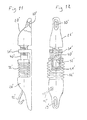
- FIG. 1 there are shown two individual implants, generally right and left designated by 1 and comprising a lower end rod 2 and an upper end rod 3 between which is interposed a deformable hydraulic element 4 which has been shown under form of a cylinder-piston assembly but which in reality would rather be realized in the form of a metal bellows to prevent hydraulic fluid from leaking.
- this element deformable can be of the telescopic or otherwise deformable type, for example an enclosure cylindrical elastic longitudinally, but not transversely.
- Rods 2 and 3 are guided in the extension of one another to move along the same vertical axis and adopt spread or close positions depending on the greater or lesser filling of the deformable element 4.
- the lower and upper ends 2, 3 have means for connection 5, 6 in the form of joints.
- Each element 1 is associated with a lower pedicle screw 10 and a upper pedicle screw 11, the threaded parts of which are fixed in the vertebral pedicles correspondents.
- the posterior end of the pedicle screws 10, 11 is received in the ends 5 and 6 in the manner of a joint allowing angular movement at least in the plane consisting of element 1 and connecting element 7.
- the articulation can have a additional degree of freedom or be realized in spherical form giving a degree of freedom rotating in all directions.
- the screws 10, 11 are fixed and articulated respectively at the ends 8 and 9, of the connecting element 7 by articulations allowing also an angular movement in the common plane, for example sagittal, of the element 1 and of its connecting element 7.
- the two deformable elements 4 of the pair of individual implants which form the implant complex shown in the drawing, are connected by a pipe 12 on which is disposed a hydraulic circuit element 13 shown, in the example, in the form of a slide valve.
- any variation in volume of liquid of one of the elements is offset by a change in volume in opposite directions in the other so that the rotation of the pedicle screws in one direction on one of the elements results in a rotation of the screws pedicle in the other direction and having substantially the same absolute angular value.
- the vertebrae can be left free to rotate in relation to each other in the plane frontal of the spine when the movements are slow and on the contrary immobilize the screws or brake strongly their rotation when the movements tend to be fast. We can thus obtain a damping effect in rotation while allowing freedom of rotation for slow movements.
- the element 13 is an element making it possible to impose the sending of the hydraulic fluid in one of the deformable elements 4 and the subtraction of the same volume of liquid in the other element 4, this sending then being followed by a closing of the communication, it is possible, after having implanted the two individual implants at given pedicle screw angles, cause, after a certain time, by external command, for example by command transcutaneous magnetic, a modification of the angle and thus cause, in small steps, a straightening of a vertebral deformation.
- Means may be provided for exerting a constant continuous pressure or intermittent in the bellows 4, so as to permanently stress the skeletal parts of which the position must be corrected.
- each implant can also be used individual with its connecting rod as a completely independent element and order separately each of the elements without any interconnection 12 to ensure some or all the functions of modification of length and therefore of angulation, as well as damping viscoelastic.
- the implant element is also associated with a device allowing to supply a deformable element 4 with high pressure liquid, if necessary, from a deformable bellows functioning for example as a pump actuated by the body, as described by the above request.
- a deformable bellows functioning for example as a pump actuated by the body, as described by the above request.
- this means of supply and discharge can be common to both implants.
- FIG. 2 shows a complex implant similar to that of claim 1 but in which the connecting rods 7 are articulated at the free ends or heads of the screws pedicle while the individual deformable implant is articulated in the intermediate position, this which gives an inversion of the rotational movement with respect to that represented in FIG. 1, and further away from the rear, the center of rotation of each pedicle screw.
- FIG. 3 shows an identical complex implant, for the implants individual 1, to that shown in Figure 2.
- the connecting element 7 which was a simple rigid rod, is replaced by a connecting element 14 formed in the manner of an implant individual and therefore comprising two ends 15, 16 capable of moving longitudinally relative to each other with the interposition of a hydraulic element deformable 17, which makes it possible to have a connecting element whose length can be modified if if desired or which can itself have a damping effect similar to that of the implant 1 proper if this function is present.
- the two elements 17 of the two individual implants shown are connected by a pipe 18 with the interposition of an element 19 of the hydraulic circuit.
- FIG. 4 there is shown schematically a practical embodiment of the device of FIG. 3 (in which the pipes and the elements of hydraulic circuits 13, 17).
- the individual implant shown has a hydraulic bellows 4 carrying on its upper face a part with an arm forming the rod 3, on its lower face a tray with an arm 2 forming the lower rod, said rods having joints 5 and 6 for pedicle screws 10, 11.
- the element 14 includes a hydraulic bellows 17, the lower plate carries an arm 15 and the upper end carries an arm 16, said bottom carrying, at their free end, the joints 8, 9 receiving the posterior ends of the screws 10, 11. It is possible optionally mechanically joining an arm of element 1 and another arm of element 14 or on the contrary leave all of these elements independent, the connection being effected only by screws 10, 11.
- FIG. 5 there is now shown a device similar to that of Figure 1 with the only difference that one of the deformable devices or bellows 4 has been replaced by a deformable device 20, which can also be produced in the form of a bellows, and in which the attachment points of the lower 2 and upper 3 arms have been reversed, so that an increase in the volume of the device 20 causes, unlike the increase in volume of the device 4, a shortening of the implant element instead of an elongation.
- this can be implemented either to cause a lordosis or reverse, depending on the desired goal, for example by acting in stages from a external control, i.e. to achieve a perfectly symmetrical damping effect in the event of spontaneous rotational movement between the vertebrae, i.e. again to simultaneously ensure the two functions thanks to more complex circuits.
- FIG 6 there is shown an assembly according to Figure 5 but in which the elements connecting 7 are arranged, as in Figure 2, so that the center of rotation of the screws pedicle is placed at the very ends of the screws.
- FIG. 7 a complex implant has been shown which also allows relationships symmetrical in the sagittal plane as shown in Figure 6 but in which the rod of link 7 of each of the individual implants has been replaced with link elements themselves of variable length, the one on the left being a connecting element 14 as shown in Figure 3 while the right connecting element also has a reversal of action at the bellows.
- the left and right rotational movements are symmetrical in the sagittal plane.
- Figure 8 there is shown schematically an embodiment similar to the Figure 4 but in which we see that by reversing the ends of bellows on which the arms are fixed, a movement in the opposite direction to that of FIG. 4 is obtained.
- the implant 26 on the right also has two end pieces arranged in the extension of one another, namely 27 and 28, the ends 29 and 30 of which are similar to ends 24 and 25 to receive the pedicle screws without possibility of movement of the screw by compared to the end which carries it.
- the end piece 27 has, from the end 29, a part in the form of an elongated threaded rod leading to the mobile part of a hydraulic element deformable 32 similar to element 23 or element 4. It is therefore understood that if the element deformable 32 deforms and causes a relative movement, for example of spacing or distraction between pieces 27 and 28, the movement of piece 27 relative to piece 28 will cause the part 27 to rotate because its threaded rod moves in the fixed nut 31.
- the element 20 is identical to that of Figure 9.
- the other implant 33 has an end piece 28 is ending with an end 30 allowing the fixing and blocking of an anchoring screw.
- the element 33 comprises a second end piece 34 with its end 35 for the receiving and blocking the anchor screws, this part 34 being connected to the element 28 so as to be immobilized in translation but free to rotate about the axis of the part 34.
- the movable part 36 of the deformable element 39 has a piece in the form of a threaded nut 37 through which passes a threaded portion 38 of the part 34. It is therefore understood that when the deformable element 39 is deformed, the movement of the moving part 36 will cause the part to rotate end 34 around its axis but without translation relative to the end piece 28, of so that the end 35 rotates without translational movement relative to the end 30.
- FIG. 11 and 12 there are shown embodiments of the plane 26 of Figure 9.
- the end pieces 25 and 28 have a tapered shape at the nose of dolphin and have transverse passages forming the ends 29 and 30 and allowing, in a completely conventional way, the fixing of a pedicle screw.
- the portion forming a nut 31 is carried by the lower part 27.
- This nut 31 is crossed by a rod threaded 40 rigidly carried by the upper end piece 28 so that the displacement axial of this rod causes the part 28 to rotate relative to the part 27.
- the threaded rod 40 enters a pot 41 received tightly inside of the hydraulic bellows 32 acting as a mobile element and the rod 40 can rotate in this pot around its axis being retained inside the pot by a circlip 42.
- FIG. 13 one sees an embodiment of an implant 33 according to the Figure 10 with an upper end 28 and a lower end piece 34 which has arms 43 leading to a bearing 44 inside which can freely rotate, while being retained axially by a circlip 45 a threaded rod 46 integral with the part 28 and capable of turning inside a nut 47 which has a pot 48 tightly fixed on the metal bellows 49 soft end secured to the end piece 34. It is understood that any movement of the bellows causes axial movement of nut 47, which causes rotation without axial movement of the part 28 relative to the part 34.
- the neutral point of the spine will have adapted thanks to the reorganization of skeletal and paraspinal tissues, which will reduce the burden of prosthesis in standing position.
- This implant 1 comprises two end pieces 51 and 52 in the shape of a dolphin head, having at their most extreme part, holes or eyelets 53 and 54 which can be arranged to be crossed by pedicle screws whose heads can be securely fixed at the holes of 53, 54. By varying, these holes can be arranged so as to allow articulation of the head of the pedicle screw and therefore an angular displacement between the end element and the screw which it door. Between the two end pieces 51 and 52 is disposed a third piece 55 movable relative to the two ends.
- the part 55 has the shape of a stirrup, one of the arms of which 56 supports a metal bellows 57 in a sealed manner, the free end of which is fixed in a sealed manner against a part 58 capable of sliding relative to the stirrup 55 and bearing, in a journalling manner, by means of a circlip, but axially non-movable relative to the part 58, a threaded rod 59 which passes through a complementary tapping of the second branch 60 of the part 55.
- a sealed cavity 61 serving to high pressure chamber and in which there is a hermetically sealed bellows 62 and in which has been vacuumed, the stiffness of this bellows being however sufficient for it to stretch spontaneously to expand and increase in volume even when surrounded by high pressure prevailing in chamber 61.
- Chamber 61 communicates via a non-deformable conduit 63, with the interior of the metal bellows 57 by means of a high pressure valve 64 housed in branch 56, this valve having a tubular soft iron drawer 65 normally pushed back by a spring in the position closing off the passage to the bellows 57.
- the interior of the bellows 57 communicates, moreover, by means of a low valve.
- pressure 66 provided with a plunger core identical to the core 65, located in room 58, with the volume 67, surrounding the various parts contained inside the deformable sleeve, waterproof 68, at the two ends of which the ends of the parts 51 and 52 emerge, this volume 67 forming the low pressure volume.
- the high pressure tank 61 is recharged by means of a bellows metal 69, of diameter significantly smaller than that of the bellows 57 and which is interposed between parts 51 and 55.
- This bellows 69 when parts 51 and 55 move away, expands and sucks liquid from the low pressure chamber 67 via a non-return valve back 70.
- the high pressure generated in the bellows 69 penetrates liquid, under very high pressure, into the upper chamber pressure 61 by means of a non-return valve 71.
- the deformation of the bellows 69 need not be of great amplitude; at on the contrary, it is preferable that the interval between the part 51 and the part 56 is small and that the stroke oscillation between parts 51 and 55 is limited, a multitude of oscillations, for example during of the subject's walking or changes in body position sufficient to generate high pressure to supply the chamber 61.
- the two parts 51 and 52 can only move, relative to each other, by a very small race, and it therefore ensures the maintenance in the chosen position of the two skeletal elements to which they are anchored, for example two vertebrae.
- implants By associating with an implant of this kind a connecting rod similar to the rods 7 and providing, at the ends of parts 51 and 52, spans of articulations allowing pivoting pedicle screws relative to said ends, implants can also be produced according to Figures 1,2, or 5, or 6.
- controllable valves such as valves 13, 19 or 64 or 66, instead to be ordered directly via a ferromagnetic plunger likely to be attracted to a magnet placed on the surface of the skin near the valve, could be controlled, in a manner known per se in hydraulics, by a small pilot valve, easier to operate because having a plunger of lower inertia, the pilot valve sending pressure to the actual shut-off valve to open it, closing the pilot valve, on the contrary causing the main valve to close.
- the implants according to the invention are delivered with a temporary element removable which keeps them in a desired spacing position between the two elements ends and the surgeon removes, once he has implanted the implant and fixed the screws pedicle or other means of anchoring to the ends of the implant.
- the invention also relates to a therapeutic surgical method consisting in ensure a modification of the position of two portions or elements of the skeleton, for example, two vertebrae, in which, at least one implant element according to the invention is implanted, one fixes one of the ends by means of anchoring to one of the skeletal portions or elements, and the other end by means of anchoring to the other portion or skeletal element, after having, possibly, a first correction of the relative position of said two portions or elements, we heal the path first and the tissues on which we intervened, then we control, preferably by non-invasive control means, movement or force correction by correspondingly biasing the two end pieces of the implant, or the anchoring means, one relative to the other.
- This displacement can be caused directly by the patient's body and, in this case, authorizes the displacement by an authorization of deformation of the mobile element, for example a hydraulic bellows, then the movement being completed, all movements are prohibited subsequent by blocking said deformable element.
- an authorization of deformation of the mobile element for example a hydraulic bellows
- one causes temporarily a deformation of the movable element by applying a force allowing to obtain the desired displacement, after which we block and prevent the movement from the deformable element.
- the mobile element is allowed to exert a permanent force, preferably constant or possibly gradually variable, between the two ends and therefore the two skeletal portions or elements with a insufficient force intensity to cause a sudden change in size and a damage to the tissue opposing this dimensional variation, but sufficient to cause, as it is known in the surgical field, slow deformation and adaptation of different fabrics until reaching the desired corrected position.
- a permanent force preferably constant or possibly gradually variable
- Such a process is particularly applicable to the correction of scoliosis or kypho-scoliosis.
- this force can advantageously be between a few daN at 25 or 30 daN.
- the device can advantageously include force or pressure sensors for limit or adjust the force to be exerted.
- force or pressure sensors for limit or adjust the force to be exerted.
- Such miniaturized sensors are available in the trade.
- the non-invasive control means can be magnets which, outside the body, can move or attract a ferromagnetic mass, such as a drawer valve, against a spring or elastic return means, which returns the mass to its position initial, once the magnet is removed.
- a ferromagnetic mass such as a drawer valve
Abstract
Description
La présente invention concerne un implant squelettique et notamment un implant destiné à
assurer des liaisons
entre au moins deux éléments du squelette humain, notamment deux vertèbres, ledit
implant pouvant être simple ou multiple et composé, par exemple, de deux ou plusieurs implants
individuels.The present invention relates to a skeletal implant and in particular an implant intended to provide connections
between at least two elements of the human skeleton, in particular two vertebrae, said implant being able to be single or multiple and composed, for example, of two or more individual implants.
Un nouvel implant squelettique, utilisable pour assurer une liaison entre au moins deux éléments du squelette humain, et notamment deux vertèbres, a été décrit dans la demande EP-A 0820731 et la demande US Serial number 08/897 673A new skeletal implant, usable to provide a link between at least two elements of the human skeleton, and in particular two vertebrae, has been described in application EP-A 0820731 and the request US Serial number 08/897 673
Ces demandes décrivent des implants qui se caractérisent, notamment, par le fait qu'ils possèdent une longueur ou dimension variable, les deux extrémités de l'implant étant susceptibles de s'éloigner ou de se rapprocher l'une de l'autre activement et/ou passivement, par exemple, suivant l'axe longitudinal de l'implant, grâce à l'interposition d'un élément déformable, par exemple un élément hydraulique, des moyens de commande et/ou de régulation étant prévus, de façon à permettre d'obtenir un changement de dimension de l'implant pour modifier la distance entre les deux éléments osseux et/ou pour assurer un amortissement visqueux ou viscoélastique ajustable autorisant un mouvement lent entre les deux éléments osseux et s'opposant davantage à un déplacement plus brusque.These applications describe implants which are characterized, in particular, by the fact that they have a variable length or dimension, the two ends of the implant being likely to move away or get closer to each other actively and / or passively, by example, along the longitudinal axis of the implant, thanks to the interposition of a deformable element, for example a hydraulic element, control and / or regulation means being provided, so as to allow a change in dimension of the implant to modify the distance between the two bony elements and / or to ensure viscous or viscoelastic damping adjustable allowing a slow movement between the two bony elements and opposing more to a more abrupt movement.
Si nécessaire, le maintien d'une haute pression hydraulique suffisante peut être assuré en utilisant un effet de pompe mécanique, actionné par les mouvements du corps, avec clapet de limitation de pression, coopérant avec un réservoir basse pression.If necessary, the maintenance of sufficient high hydraulic pressure can be ensured by using a mechanical pump effect, activated by body movements, with a check valve pressure limitation, cooperating with a low pressure tank.
Dans cette demande sont décrits, par exemple, des implants doubles, constitués de deux implants individuels susceptibles d'être disposés respectivement des deux côtés du rachis pour relier deux vertèbres, chacun des deux éléments étant ainsi fixé à une vertèbre inférieure par un moyen d'ancrage, tel qu'une vis pédiculaire, et à une vertèbre supérieure, adjacente ou plus éloignée, par également chaque fois un moyen d'ancrage, tel qu'une vis pédiculaire.In this application are described, for example, double implants, consisting of two individual implants which can be placed on both sides of the spine respectively connect two vertebrae, each of the two elements being thus fixed to a lower vertebra by a anchoring means, such as a pedicle screw, and to an upper, adjacent or more vertebra distant, also each time an anchoring means, such as a pedicle screw.
Dans le cas d'un implant double composé de deux implants individuels agissant sur les mêmes structures squelettiques, il a également déjà été prévu dans lesdites demandes EP-A-082031 et US 08/897 673 d'interconnecter de façon hydraulique les deux implants individuels de façon à autoriser des mouvements de pivotement des éléments osseux l'un par rapport à l'autre, à savoir un pivotement latéral dans le plan frontal du rachis, par augmentation de longueur de l'un des implants individuels et diminution concomitante de longueur de l'autre implant, pour une correction de déformation et/ou un amortissement de flexion latérale.In the case of a double implant composed of two individual implants acting on the same skeletal structures, it has also already been provided for in said applications EP-A-082031 and US 08/897 673 to hydraulically interconnect the two individual implants so as to allow pivoting movements of the bone elements, one with respect to the other, namely a lateral pivoting in the frontal plane of the spine, by increasing length of one of the individual implants and concomitant decrease in length of the other implant, for correction of deformation and / or lateral flexion damping.
Grâce à des moyens de commande, par exemple des moyens non invasifs de type magnétique, on peut assurer les modifications de dimension désirée des implants individuels et/ou les modifications du coefficient d'amortissement de l'élément jouant un rôle d'amortisseur. De plus, il peut être prévu des moyens modifiant automatiquement le coefficient d'amortissement ou la viscosité en fonction des mouvements corporels.By means of control, for example non-invasive means of the type magnetic, we can ensure the desired size changes of individual implants and / or modifications to the damping coefficient of the element acting as a damper. In addition, means may be provided which automatically modify the coefficient damping or viscosity depending on body movements.
L'intégralité du contenu des susdites demandes EP-A-0820731 et US 08/897 673 est incorporée par référence dans la présente demande pour faire partie constitutive de la description.The entire content of the above applications EP-A-0820731 and US 08/897 673 is incorporated by reference in this application to form part of the description.
En résumé la présente invention se propose de réaliser et de perfectionner un dispositif implantable comprenant au moins un implant muni de deux extrémités susceptibles d'être fixées, par des moyens d'ancrage, sur au moins deux portions ou parties de squelette et comprenant des moyens de déplacement, de préférence au moins partiellement réversible, entre lesdites deux extrémités, agencés pour provoquer/ou maintenir un déplacement entre lesdites portions ou éléments de squelette.In summary, the present invention proposes to produce and improve a device implantable comprising at least one implant provided with two ends capable of being fixed, by anchoring means, on at least two portions or parts of skeleton and comprising means of movement, preferably at least partially reversible, between said two ends, arranged to cause / or maintain movement between said portions or skeleton elements.
Ce déplacement peut un déplacement rectiligne et/ou courbe, par exemple être un déplacement d'allongement, encore appelé de distraction, ou un déplacement de raccourcissement, dit de compression, ou un déplacement en rotation, cette rotation pouvant être isolée ou au contraire associée à une distraction ou une compression.This displacement can a rectilinear and / or curved displacement, for example be a lengthening displacement, also called distraction, or a displacement of shortening, called compression, or a rotational displacement, this rotation being able to be isolated or on the contrary associated with a distraction or compression.
Dans la forme de réalisation la plus simple, dans laquelle lesdits moyens de déplacement sont capables de maintenir, mais non de provoquer le déplacement, ces moyens de déplacements sont contrôlés par des moyens de commande, de préférence non invasifs, qui permettent de les libérer de façon à permettre au patient, ou à un intervenant, de modifier la position relative des deux portions ou éléments de squelette, après quoi lesdits moyens de commande sont actionnés pour bloquer l'implant dans cette nouvelle position, un déplacement en sens inverse ou réversible restant possible si l'on agit à nouveau sur les moyens de commande, par exemple dans le cas où les déplacements auraient été trop importants.In the simplest embodiment, wherein said means for moving are able to maintain, but not cause displacement, these means of displacement are controlled by control means, preferably non-invasive, which allow them to be release to allow the patient, or a caregiver, to change the relative position of two skeleton portions or elements, after which said control means are actuated to block the implant in this new position, movement in the opposite direction or reversible remaining possible if one acts again on the control means, for example in the case where the displacements would have been too important.
Dans une autre forme de réalisation, préférée, de l'invention, lesdits moyens de déplacement comportent un moyen moteur permettant d'imposer un déplacement entre lesdites extrémités en exerçant une force entre elles.In another preferred embodiment of the invention, said means for displacement comprise a motor means making it possible to impose a displacement between the said ends by exerting a force between them.
Dans une forme de réalisation particulière, cette force peut être exercée temporairement, c'est-à-dire pendant un instant assez court, dans le but de provoquer un déplacement thérapeutiquement désirable entre les deux portions ou éléments de squelette, un tel déplacement étant souvent prévu pour une faible amplitude, car rapidement contrecarré par les structures anatomiques qu'il convient de pas traumatiser. A la fin de cet instant, les moyens de commande permettent de bloquer les deux extrémités l'une par rapport à l'autre et de maintenir l'implant dans sa nouvelle position.In a particular embodiment, this force can be temporarily exerted, that is to say for a fairly short time, in order to cause a displacement therapeutically desirable between the two skeleton portions or elements, such displacement being often planned for a weak amplitude, because quickly thwarted by the structures anatomical that should not be traumatized. At the end of this instant, the control means block the two ends relative to each other and hold the implant in its new position.
Dans une autre forme de réalisation, au contraire, lesdits moyens de déplacement sont capables d'exercer une force permanente anatomiquement active entre lesdites deux extrémités, cette force pouvant être constante ou variable, de façon à exercer, sur l'environnement anatomique, une contrainte qui va progressivement autoriser un déplacement anatomiquement souhaité entre lesdites deux portions ou éléments de squelette, ces moyens moteurs étant commandables par des moyens de commande permettant d'autoriser ou d'interrompre leur fonctionnement, et/ou d'ajuster l'intensité de la force.In another embodiment, on the contrary, said displacement means are capable of exerting an anatomically active permanent force between said two ends, this force can be constant or variable, so as to exert on the environment anatomical, a constraint that will gradually allow an anatomical displacement desired between said two portions or skeleton elements, these motor means being controllable by control means making it possible to authorize or interrupt their operation, and / or adjust the intensity of the force.
Eventuellement, l'implant peut également comprendre des moyens d'amortissement visqueux ou viscoélastiques pouvant être mis en oeuvre lorsque l'implant est bloqué dans sa dimension ou lorsque l'implant est libéré ou lorsqu'il exerce sa force active permanente. De tels moyens ont été décrits dans les demandes européenne et américaine précitées.Optionally, the implant may also include damping means viscous or viscoelastic that can be used when the implant is blocked in its dimension or when the implant is released or when it exerts its permanent active force. Such means have been described in the aforementioned European and American applications.
Lesdits moyens de déplacement et, s'il y a lieu, lesdits moyens moteurs peuvent être de type hydraulique, et/ou mécanique, et/ou électrique, une réalisation hydraulique étant préférée.Said displacement means and, if necessary, said motor means can be hydraulic, and / or mechanical, and / or electrical type, a hydraulic embodiment being preferred.
Dans une forme de réalisation utilisant des moyens hydrauliques, l'implant comporte
préférentiellement :
un circuit d'amortissement visqueux ou viscoélastique comprenant :
éventuellement un élément élastique opérationnellement interposé entre lesdits deux éléments d'extrémités d'implant, et un élément amortisseur hydraulique comprenant au moins un élément déformable sensible à la vitesse d'une variation dimensionnelle de l'implant et communiquant avec un réservoir de décharge par l'intermédiaire d'un moyen d'étranglement,
- et des moyens de commande, de préférence, actionnables depuis l'extérieur du corps du patient, pour modifier la dimension de l'implant, et/ou la force exercée par l'implant et/ou les propriétés d'amortissement.
a viscous or viscoelastic damping circuit comprising:
optionally an elastic element operatively interposed between said two implant end elements, and a hydraulic damping element comprising at least one deformable element sensitive to the speed of a dimensional variation of the implant and communicating with a discharge tank by the '' through a means of strangulation,
- and control means, preferably operable from outside the patient's body, to modify the size of the implant, and / or the force exerted by the implant and / or the damping properties.
Bien entendu une même pièce, par exemple un élément déformable, peut faire partie constitutive de plusieurs des constituants définis ci-dessus.Of course the same part, for example a deformable element, can be part constitutive of several of the constituents defined above.
Le circuit de recharge du réservoir haute pression est destinée à jouer, en fait un rôle de pompe très haute pression permettant d'établir et de maintenir une pression élevée dans un réservoir haute pression.The charging circuit of the high pressure tank is intended to play, in fact a role of very high pressure pump for establishing and maintaining high pressure in a high pressure tank.
De préférence, notamment dans le cas, préféré, où l'élément déformable du circuit de recharge haute pression est sensible à des mouvements ou des positions corporels du patient recevant l'implant, on prévoit que cet élément déformable ait une petite surface, comparé à la surface active de l'élément qui lui transmet la force en provenance de l'organisme, de façon à assurer un effet différentiel multiplicateur de pression, étant entendu que l'on peut admettre qu'à chaque sollicitation, seule une faible quantité de fluide sous très haute pression est adressée vers la chambre haute pression.Preferably, especially in the preferred case, where the deformable element of the circuit high pressure refill is sensitive to movements or body positions of the patient receiving the implant, it is expected that this deformable element has a small surface, compared to the active surface of the element which transmits force to it from the organism, so as to ensure a differential pressure multiplier effect, it being understood that it can be admitted that each request, only a small quantity of fluid under very high pressure is sent to the high pressure chamber.
L'élément déformable du circuit de recharge du réservoir haute pression peut aussi être actionné par des moyens extérieurs tout en restant implanté. Ainsi, par exemple, cet élément déformable peut se présenter sous forme d'une pompe, de préférence réalisée par un soufflet métallique, implanté sur une partie corporelle à un niveau où on peut lui appliquer une pression externe, par exemple implanté sur la face postérieure du sacrum, permettant à la main d'un intervenant, à travers les plans anatomiques externes, d'actionner cette pompe ou soufflet.The deformable element of the high pressure tank recharging circuit can also be operated by external means while remaining installed. So, for example, this element deformable can be in the form of a pump, preferably produced by a bellows metallic, implanted on a body part at a level where it can be applied pressure external, for example implanted on the posterior surface of the sacrum, allowing the hand of a intervening, through the external anatomical planes, to activate this pump or bellows.
En variante, cette pompe pourrait être de type magnétique ou électromagnétique, en possédant, par exemple, un noyau mobile actionnant un petit piston ou soufflet sous l'influence d'une force électromagnétique d'origine externe.As a variant, this pump could be of the magnetic or electromagnetic type, in having, for example, a movable core actuating a small piston or bellows under the influence electromagnetic force of external origin.
On comprend également que l'on incorpore, dans la présente demande, les variantes et équivalents utilisant des moyens moteurs et/ou amortisseurs, non-hydrauliques assurant les mêmes fonctions de modification durable et ajustable de dimension et/ou de force et/ou de modification ajustable ou variation de coefficient d'amortissement.It will also be understood that the variants and equivalents using non-hydraulic motor and / or damping means ensuring the same functions of durable and adjustable modification of dimension and / or strength and / or adjustable modification or variation of damping coefficient.
Uniquement à titre d'exemple, un implant de type uniquement mécanique peut comprendre une première extrémité, mobile en translation par rapport à la deuxième extrémité, et solidaire d'une tige immobilisée par un cliquet sensible à un moyen de commande magnétique externe pour bloquer ou libérer ladite tige, un moyen moteur étant interposé entre ladite tige et ladite deuxième extrémité, ce moyen moteur pouvant être réalisé sous forme d'un ressort ou d'un autre élément élastique préchargé tendant à déplacer l'une des extrémités par rapport à l'autre lorsque l'on libère le cliquet, le mouvement pouvant être réversible, au moins une fois, par exemple, en intercalant entre le ressort et ladite deuxième extrémité une pièce d'appui de ressort que l'on peut déplacer, grâce à d'autres moyens de commande magnétique, de façon à détendre au moins partiellement le ressort. En variante, l'implant peut comporter plusieurs ressorts disposés parallèlement et susceptibles d'être mis en oeuvre séparément par des moyens de libération sensibles à des moyens de commande.For example only, a purely mechanical implant can include a first end, movable in translation relative to the second end, and secured to a rod immobilized by a pawl sensitive to a magnetic control means external to block or release said rod, a motor means being interposed between said rod and said second end, this motor means being able to be produced in the form of a spring or a other preloaded elastic member tending to move one end relative to the other when the pawl is released, the movement can be reversible, at least once, by example, by inserting between the spring and said second end a spring support piece which can be moved, using other magnetic control means, so as to relax at least partially the spring. Alternatively, the implant may include several springs arranged in parallel and capable of being implemented separately by means of release sensitive to control means.
Dans une autre forme de réalisation, un implant peut comporter des moyens de déplacement de type électromagnétique, par exemple un solénoïde avec un noyau plongeur, le solénoïde étant solidaire d'une des extrémités d'un implant et le noyau plongeur de l'autre extrémité, des moyens de blocage étant, de préférence prévus pour immobiliser le noyau par rapport au solénoïde dans au moins deux postions différentes, le solénoïde étant susceptible d'être alimenté, par un moyen de commande, à partir d'une source d'énergie électrique, par exemple une pile implantée et/ou un accumulateur rechargeable par transmission d'antenne à couplage transcutané.In another embodiment, an implant may include means for electromagnetic displacement, for example a solenoid with a plunger, the solenoid being secured to one end of an implant and the plunger core to the other end, blocking means being preferably provided for immobilizing the core by relation to the solenoid in at least two different positions, the solenoid being susceptible to be supplied, by a control means, from a source of electrical energy, by example an implanted battery and / or an accumulator rechargeable by antenna transmission to transcutaneous coupling.
De telles réalisations sont réversibles au sens de l'invention car elles permettent, si on le souhaite, d'obtenir une modification en sens inverse, au moins en partie, de la modification dimensionnelle établie.Such embodiments are reversible within the meaning of the invention because they allow, if it is wishes to obtain a change in reverse, at least in part, from the change dimensional established.
La présente invention permet également de perfectionner les mouvements ou forces de rotation autorisés ou imposés par un implant ou un ensemble d'au moins deux implants individuels, dans le plan frontal et/ou sagittal et/ou horizontal.The present invention also makes it possible to perfect the movements or forces of rotation authorized or imposed by an implant or a set of at least two implants individual, in the frontal and / or sagittal and / or horizontal plane.
Par exemple l'invention permet de fournir des implants de ce type permettant d'imposer
des mouvements de rotation symétriques, c'est-à-dire de même sens et de même valeur de
rotation des vis pédiculaires ou moyens d'ancrage similaires des deux éléments d'implant
individuel, ou au contraire des mouvements antisymétriques, c'est-à-dire de sens opposés, ou
encore indépendants l'un de l'autre.
D'une façon générale, le mouvement ou force de rotation contrôlé entre les deux moyens
d'ancrage d'un implant selon l'invention, et le cas échéant la coordination des mouvements ou
forces de rotation des moyens d'ancrage de plusieurs implants, par exemple les implants
individuels d'un implant double, permettra, selon les besoins, de se rapprocher beaucoup plus du
mouvement naturel théoriquement possible ou souhaitable entre les deux parties osseuses
auxquelles sont fixées les moyens d'ancrage, pour imposer des déplacements progressifs, par
exemple pour des corrections, et/ou des amortissements progressivement modifiables, partant
par exemple de la rigidité pendant une phase de consolidation osseuse ou de cicatrisation vers
une mobilité progressive, permettant, par exemple, de sauvegarder une articulation.For example, the invention makes it possible to provide implants of this type making it possible to impose symmetrical rotational movements, that is to say of the same direction and of the same rotation value of the pedicle screws or similar anchoring means of the two individual implant elements, or on the contrary antisymmetric movements, that is to say in opposite directions, or even independent of each other.
In general, the movement or force of rotation controlled between the two anchoring means of an implant according to the invention, and where appropriate the coordination of the movements or forces of rotation of the anchoring means of several implants, for example the individual implants of a double implant, will make it possible, as necessary, to approach much more the theoretically possible or desirable natural movement between the two bony parts to which the anchoring means are fixed, in order to impose progressive displacements, by example for corrections and / or gradually modifiable cushioning, starting for example from rigidity during a bone consolidation or healing phase towards progressive mobility, allowing, for example, to save a joint.
L'implant squelettique présente un premier et un second élément d'extrémité, des moyens d'ancrage dans des parties osseuses reliés respectivement auxdits premier et second éléments d'extrémité, au moins un élément déformable relié respectivement auxdits premier et second moyens d'ancrage, et des moyens autorisant un mouvement non rectiligne, notamment une rotation entre lesdits moyens d'ancrageThe skeletal implant has first and second end members, means anchoring in bone parts connected respectively to said first and second elements end, at least one deformable element connected respectively to said first and second anchoring means, and means allowing non-rectilinear movement, in particular a rotation between said anchoring means
L'implant peut comporter des moyens autorisant une rotation entre lesdits éléments d'extrémité.The implant may include means allowing rotation between said elements end.
Ledit élément déformable peut être déformable en rotation.Said deformable element can be deformable in rotation.
L'implant peut comporter des moyens autorisant une rotation d'au moins un desdits moyens d'ancrage par rapport à la pièce d'extrémité à laquelle il est relié.The implant may include means allowing rotation of at least one of said anchoring means relative to the end piece to which it is connected.
Le mouvement de rotation précité peut aussi être associé à des mouvements en translation, de sorte que le mouvement résultant peut être un déplacement complexe non rectiligne.The aforementioned rotational movement can also be associated with translational movements, so that the resulting movement can be a complex non-rectilinear movement.
Selon un perfectionnement, l'implant squelettique, présentant un premier et un deuxième élément d'extrémité, des moyens d'ancrage dans des parties osseuses, par exemple par l'intermédiaire de vis, telles que par exemple des vis pédiculaires situées auxdites extrémités, au moins un élément déformable, par exemple, un élément hydraulique, contenant un fluide hydraulique indéformable, et interposé entre les deux éléments d'extrémité, et des moyens d'actionnement de l'élément déformable, par exemple, s'il y a lieu, des moyens de circuit hydraulique reliés audit au moins un élément déformable interposé entre lesdites extrémités, et susceptibles de permettre une modification durable, de préférence obtenue progressivement, de la distance ou de la force entre lesdites deux extrémités et/ou un amortissement viscoélastique des mouvements entre lesdites deux extrémités, lesdits moyens d'actionnement, par exemple lesdits moyens de circuit hydraulique, étant sensibles à des moyens de commande, de préférence, actionnables depuis l'extérieur du corps du patient, se caractérise en ce que lesdits moyens de fixation ou d'ancrage sont fixés auxdites deux extrémités par des moyens de connexion articulés et en ce que lesdits moyens de fixation ou d'ancrage sont en outre reliés l'un à l'autre par un élément de liaison rigide relativement parallèle à l'axe géométrique reliant lesdites deux extrémités de l'implant et situé à une certaine distance dudit axe, par des moyens de connexion également articulés, par exemple de façon à réaliser entre lesdits quatre points de connexion, un quadrilatère déformable, permettant un mouvement de rotation angulaire desdits moyens de fixation ou d'ancrage l'un par rapport à l'autre.According to an improvement, the skeletal implant, having a first and a second end element, means for anchoring in bone parts, for example by through screws, such as for example pedicle screws located at said ends, at the minus a deformable element, for example a hydraulic element, containing a fluid undeformable hydraulic, and interposed between the two end elements, and means actuating the deformable element, for example, if necessary, circuit means hydraulics connected to said at least one deformable element interposed between said ends, and likely to allow a lasting modification, preferably obtained gradually, of the distance or force between said two ends and / or viscoelastic damping movements between said two ends, said actuating means, for example said hydraulic circuit means, being sensitive to control means, preferably, operable from outside the patient's body, is characterized in that said means of fixing or anchoring are fixed to said two ends by articulated connection means and in that said fixing or anchoring means are further connected to each other by a rigid connecting element relatively parallel to the geometric axis connecting said two ends of the implant and located at a certain distance from said axis, by connection means also articulated, for example so as to achieve between said four connection points, a deformable quadrilateral, allowing angular rotational movement of said means of fixing or anchoring to each other.
Ces moyens de connexion articulée peuvent être constitués d'articulations mécaniques proprement dites, ou de moyens de liaison convenablement déformables.These articulated connection means may consist of mechanical joints proper, or suitably deformable connecting means.
Les articulations peuvent être, par exemple, des articulations utilisant une rotule reçue de façon rotative dans un siège de la pièce d'extrémité, cette rotule présentant un passage à travers lequel elle peut recevoir et maintenir une partie d'un moyen d'ancrage telle qu'une vis pédiculaire. Bien entendu, tous les autres principes d'articulation telle qu'articulation à pivot peuvent être utilisés.The joints can be, for example, joints using a ball joint received from rotatably in a seat of the end piece, this ball joint having a passage through which it can receive and hold part of an anchoring means such as a screw pedicular. Of course, all the other principles of articulation such as pivot articulation can be used.
Dans une forme de réalisation, ledit élément de liaison est situé entre l'axe de l'implant et les éléments osseux auxquels l'implant est fixé, mais dans une autre forme de réalisation, ledit élément de liaison est disposé de l'autre côté de l'axe de l'implant par rapport aux éléments osseux réunis par l'implant.In one embodiment, said connecting element is located between the axis of the implant and the bone elements to which the implant is attached, but in another embodiment, said connecting element is arranged on the other side of the axis of the implant relative to the elements bone joined by the implant.
Lesdits éléments de liaison peuvent être de simples liens rigides tels que des tiges ou barreaux de longueur invariable.Said connecting elements can be simple rigid links such as rods or invariable length bars.
Cependant dans une autre forme de réalisation ces éléments de liaison peuvent eux-mêmes comporter, entre leurs extrémités, au moins une zone déformable, ce qui permet alors d'assurer des déplacements, tels que par exemple un allongement de l'implant sans rotation relative des moyens de fixation, par modification de longueur simultanée de l'élément proprement dit et de l'élément de liaison et/ou d'assurer un amortissement viscoélastique entre les éléments osseux sans mouvement de rotation desdits moyens de fixation.However in another embodiment these connecting elements can themselves have, between their ends, at least one deformable zone, which then ensures displacements, such as for example an elongation of the implant without relative rotation of the fixing means, by simultaneous modification of the length of the element itself and of the connecting element and / or ensuring viscoelastic damping between the bone elements without rotational movement of said fixing means.
On peut réaliser un implant complexe conformément à l'invention en utilisant deux
implants individuels disposés, par exemple, côte à côte, par exemple de part et d'autres des
apophyses épineuses du rachis, en assurant une interconnexion hydraulique permettant d'assurer
l'une au moins des fonctions suivantes :
Bien entendu les deux éléments individuels d'un implant complexe peuvent, dans un but de simplicité, utiliser des éléments hydrauliques communs, tels que, par exemple, réservoir haute pression, collecteur basse pression, moyens d'établissement de la haute pression, moyens de commande de circuit hydraulique. Of course the two individual elements of a complex implant can, for one purpose simplicity, use common hydraulic elements, such as, for example, high tank pressure, low pressure manifold, means for establishing high pressure, means for hydraulic circuit control.
Dans une autre forme de réalisation, destinée à permettre une rotation dans un plan transversal ou éventuellement oblique, par rapport à la direction générale de l'implant, c'est-à-dire à la direction reliant les deux moyens ou vis d'ancrage, l'implant squelettique, présentant un premier et un deuxième élément d'extrémité, des moyens de fixation ou d'ancrage, dans des parties osseuses, par exemple par l'intermédiaire de vis, par exemple des vis pédiculaires situées aux extrémités, au moins un élément déformable, interposé entre les deux éléments d'extrémité, et ses moyens d'actionnement, pour permettre une modification durable, de préférence obtenue progressivement, de la distance entre une extrémité et un élément mobile par rapport à ladite une extrémité, et des moyens de commande, de préférence actionnables depuis l'extérieur du corps du patient, se caractérise en ce que, ledit élément mobile est agencé pour provoquer ou autoriser une rotation de l'autre des deux extrémités autour d'un axe sensiblement parallèle audit implant.In another embodiment, intended to allow rotation in a plane transverse or possibly oblique, in relation to the general direction of the implant, i.e. to the direction connecting the two anchoring means or screws, the skeletal implant, having a first and second end element, fixing or anchoring means, in bone parts, for example by means of screws, for example pedicle screws located at the ends, at least one deformable element, interposed between the two end elements, and its actuation means, to allow a lasting modification, preferably obtained progressively, the distance between one end and a movable element with respect to said one end, and control means, preferably operable from outside the body of the patient, is characterized in that, said movable element is arranged to provoke or authorize a rotation of the other of the two ends about an axis substantially parallel to said implant.
Les moyens par lesquels le déplacement dudit élément mobile par le mouvement de l'élément déformable, transforme ce mouvement en un mouvement de rotation de ladite autre extrémité et du moyen de fixation ou d'ancrage qu'elle supporte, peut-être un moyen associant une vis et un écrou de sorte que le mouvement de translation de l'un provoque un mouvement de rotation de l'autre.The means by which the displacement of said movable element by the movement of the deformable element, transforms this movement into a rotational movement of said other end and the fixing or anchoring means which it supports, perhaps a means associating a screw and a nut so that the translational movement of one causes a movement of rotation of the other.
Dans une forme de réalisation particulière, l'élément déformable est interposé entre les deux pièces d'extrémité dont l'une est susceptible de tourner, de sorte que la déformation de l'élément déformable entraíne à la fois une rotation et une translation de l'un des éléments d'extrémité, et donc des moyens d'ancrage qu'il porte, par rapport à l'autre pièce d'extrémité, se traduisant par un mouvement hélicoïdal de l'une des pièces d'extrémité par rapport à l'autre.In a particular embodiment, the deformable element is interposed between the two end pieces, one of which is capable of turning, so that the deformation of the deformable element causes both a rotation and a translation of one of the elements end, and therefore the anchoring means that it carries, relative to the other end piece, is resulting in a helical movement of one of the end pieces relative to the other.
Dans une autre forme de réalisation, les deux pièces d'extrémité peuvent être solidaires l'une de l'autre de façon à rester écartées d'une distance invariable, l'élément mobile étant alors interposé entre cet ensemble d'éléments d'extrémité et le moyen de transformation de la déformation de l'élément mobile, en rotation de l'un des éléments d'extrémité par rapport à l'autre.In another embodiment, the two end pieces may be integral one from the other so as to remain separated by an invariable distance, the movable element then being interposed between this set of end elements and the means for transforming the deformation of the movable element, in rotation of one of the end elements relative to the other.
Dans une autre forme de réalisation, c'est l'élément déformable lui-même qui est construit pour se déformer en rotation, par exemple en utilisant une chambre déformable à piston rotatif, selon les principes bien connus de la rotation hydraulique.In another embodiment, it is the deformable element itself which is constructed to deform in rotation, for example by using a deformable chamber with rotary piston, according to the well-known principles of hydraulic rotation.
Des dispositifs susceptibles de rotation, tels qu'ils viennent d'être décrits, peuvent être particulièrement utiles dans le cas des scolioses graves ou des déstablisations dégénératives graves du rachis. On pourra alors, par exemple, fixer deux dispositifs selon l'invention de part et d'autre de l'apophyse postérieure vertébrale, entre deux étages vertébraux, et provoquer la rotation entre les deux ancrages de l'un des deux dispositifs, ou une rotation associée à un déplacement longitudinal, l'autre dispositif étant susceptible alors d'un mouvement d'adaptation géométrique complémentaire des déplacements imposés par le premier.Devices capable of rotation, as just described, can be particularly useful in the case of severe scoliosis or degenerative disorders severe spine. We can then, for example, fix two devices according to the invention on the one hand and on the other side of the posterior vertebral process, between two vertebral stages, and cause rotation between the two anchors of one of the two devices, or a rotation associated with a longitudinal displacement, the other device then being susceptible to an adaptation movement geometric complementary to the displacements imposed by the first.
Toutes sortes de déplacements complexes non rectilignes peuvent être obtenus, grâce à l'intervention, par exemple, en assujetissant le déplacement d'un moyen d'ancrage, ou d'une pièce d'extrémité, à une came ou glissière ou autre guide incurvé.All kinds of complex non-rectilinear displacements can be obtained, thanks to the intervention, for example, by subjecting the displacement of an anchoring means, or of a part end, to a cam or slide or other curved guide.
De préférence, l'implant constitué par un dispositif selon l'invention possédera une forme extérieure bien adaptée à l'environnement corporel dans lequel il se trouve. Par exemple, notamment pour des implants vertébraux, il sera avantageux de donner à chacune des deux extrémités une forme fuselée de façon à ne pas gêner les tissus voisins, d'autant plus que, grâce aux implants selon l'invention on peut aboutir à une amélioration fonctionnelle à laquelle devront être associés les muscles et ligaments, contrairement aux arthrodèses, qui se traduisent par leur atrophie.Preferably, the implant constituted by a device according to the invention will have a shape exterior well suited to the bodily environment in which it is found. For example, especially for vertebral implants, it will be advantageous to give each of the two ends a tapered shape so as not to interfere with neighboring fabrics, especially since, thanks implants according to the invention can lead to a functional improvement which will have to be associated muscles and ligaments, unlike arthrodesis, which result in their atrophy.
Cette forme fuselée peut comprendre une enveloppe, de préférence déformable appliquée autour de l'implant, dont les deux extrémités, qui présentent les moyens de fixation pour les moyens d'ancrage, émergent de l'enveloppe, laquelle contient les différents autres constituants de l'implant. Le volume inteme libre dans cette enveloppe peut, de préférence, servir de réservoir de liquide basse pression. De préférence l'implant comporte à l'intérieur de cette enveloppe, l'élément mobile, qui peut être un moteur mécanique, ou, de préférence un moteur hydraulique, par exemple un soufflet hydraulique dont l'intérieur est relié, par une vanne basse pression, au volume basse pression formé dans l'enveloppe.This tapered shape may include an envelope, preferably deformable applied around the implant, including the two ends, which present the fixing means for the anchoring means emerge from the envelope, which contains the various other constituents of the implant. The free internal volume in this envelope can preferably serve as a reservoir for low pressure liquid. Preferably the implant comprises inside this envelope, the movable element, which can be a mechanical motor, or, preferably, a hydraulic motor, for example a hydraulic bellows, the interior of which is connected, by a low pressure valve, to the low pressure volume formed in the envelope.
De préférence, à l'intérieur de l'enveloppe, on trouve également un réservoir haute pression, de préférence un soufflet, et, également de préférence, un élément déformable différentiel pour envoyer du liquide sous très haute pression dans le réservoir haute pression, le réservoir haute pression étant relié à l'élément mobile également par une vanne haute pression, les deux vannes haute pression et basse pression étant, de préférence, relativement éloignées l'une de l'autre, afin de permettre facilement une commande sélective par des moyens de commande externes, tels que, par exemple, des aimants.Preferably, inside the envelope, there is also a high tank pressure, preferably a bellows, and also preferably a deformable element differential to send liquid under very high pressure into the high pressure tank, the high pressure tank being connected to the movable element also by a high pressure valve, the two high pressure and low pressure valves being preferably relatively distant one from the other, in order to easily allow selective control by means of external controls, such as, for example, magnets.
Cependant, dans une autre forme de réalisation, notamment, lorsque l'on prévoit une succession d'implants individuels à divers étages du rachis, on peut également prévoir un réservoir haute pression unique et/ou un moyen de recharge unique des réservoirs hautes pressions, situé à l'écart des différents implants individuels et relié à ceux-ci par des conduits inextensibles.However, in another embodiment, in particular, when provision is made for succession of individual implants on various stages of the spine, one can also provide a single high pressure tank and / or a single means of recharging the high tanks pressures, located away from the different individual implants and connected to them by conduits inextensible.
Le réservoir de haute pression peut être avantageusement conçu pour maintenir le liquide, qu'il contient, sous haute pression, même lorsque des quantités notables de ce liquide sont envoyées aux moyens moteurs de l'implant, provoquant une diminution sensible du volume de liquide. Ceci peut être assuré, par exemple, en réalisant le réservoir haute pression sous forme de réservoir déformable élastique de grande raideur, par exemple un soufflet métallique de grande raideur et qui est expansé lorsqu'il contient le liquide sous haute pression, ce soufflet tendant à se rétracter pour maintenir la haute pression pendant une partie importante de sa course de rétraction. En variante, ou en association avec un tel soufflet, on peut également prévoir, pour maintenir la valeur élevée de pression dans le réservoir, un accumulateur d'énergie sous forme d'une enceinte à paroi élastiquement déformable qui est comprimée, donc diminuée de volume, lorsque le liquide sous haute pression est introduit dans le réservoir haute pression, et qui se détend élastiquement en maintenant une pression élevée lorsque du liquide est soutiré hors du réservoir haute pression. Cet accumulateur d'énergie est, de préférence, formé par une capsule déformable, qui peut, par exemple, comprendre à son intérieur une matière facilement déformable ou un gaz, mais qui de façon particulièrement préférée présente un vide important de façon à supprimer tout risque de fuite de gaz.The high pressure tank can advantageously be designed to hold the liquid, that it contains, under high pressure, even when significant quantities of this liquid are sent to the motor means of the implant, causing a significant reduction in the volume of liquid. This can be ensured, for example, by making the high pressure tank in the form of elastic deformable reservoir of great stiffness, for example a metal bellows of great stiffness and which is expanded when it contains the liquid under high pressure, this bellows tending to retract to maintain high pressure during a significant part of its travel retraction. As a variant, or in combination with such a bellows, provision may also be made, for maintain the high pressure value in the tank, an energy accumulator in the form an enclosure with an elastically deformable wall which is compressed, therefore reduced in volume, when the high pressure liquid is introduced into the high pressure tank, and which elastically relaxes by maintaining high pressure when liquid is drawn out of the high pressure tank. This energy accumulator is preferably formed by a capsule deformable, which can, for example, easily include material inside deformable or a gas, but which in a particularly preferred manner presents a significant vacuum of in order to eliminate any risk of gas leakage.
D'autres avantages et caractéristiques de l'invention apparaítront à la lecture de la
description suivante, faite à titre d'exemple non limitatif et se référant au dessin annexé dans
lequel:
- la figure 9 représente une vue schématique d'une paire d'implants dont l'un permet un mouvement simultané axial et de rotation dans un plan transversal à la direction générale de l'implant.
- la figure 10 représente une vue schématique d'une paire d'implant dont l'un permet une rotation sans mouvement de translation, dans un plan perpendiculaire à la direction générale de l'implant,
- la figure 12 représente une vue en élévation avec section partielle de cet implant
- FIG. 9 represents a schematic view of a pair of implants, one of which allows simultaneous axial and rotational movement in a plane transverse to the general direction of the implant.
- FIG. 10 represents a schematic view of a pair of implant, one of which allows rotation without translational movement, in a plane perpendicular to the general direction of the implant,
- Figure 12 shows an elevational view with partial section of this implant
Sur les différentes figures 1 à 10 qui suivent, on suppose que le rachis s'étend dans une direction verticale et que les deux implants individuels sont disposés de part et d'autres de la succession des apophyses épineuses et que les vis pédiculaires inférieures sont vissées dans une première vertèbre et les vis pédiculaires supérieures dans une autre vertèbre, adjacente ou non, disposée au-dessus de la première. Les deux éléments individuels sont représentés dans un plan frontal, qui est le plan de la feuille du dessin. Il en résulte que les vis pédiculaires devraient être orientés dans un plan plus ou moins sagittal, donc plus ou moins perpendiculaire au plan de la feuille de dessin ou en tout cas incliné mais, pour des raisons de simplicité de représentation on les a représentées dans le même plan frontal. De même les éléments de liaison ont été représentés dans le même plan frontal alors qu'ils devraient être dans le plan perpendiculaire ou incliné qui contient les vis pédiculaires.In the various figures 1 to 10 which follow, it is assumed that the spine extends in a vertical direction and that the two individual implants are placed on either side of the succession of spinous processes and that the lower pedicle screws are screwed into a first vertebra and upper pedicle screws in another vertebra, adjacent or not, arranged above the first. The two individual elements are represented in a plane frontal, which is the plane of the drawing sheet. As a result, the pedicle screws should be oriented in a more or less sagittal plane, therefore more or less perpendicular to the plane of the drawing sheet or in any case inclined but, for reasons of simplicity of representation, has represented them in the same frontal plane. Similarly, the connecting elements have been represented in the same frontal plane when they should be in the perpendicular plane or inclined which contains the pedicle screws.
Sur la figure 1 on a représenté deux implants individuels droit et gauche généralement
désignés par 1 et comprenant une tige d'extrémité inférieure 2 et une tige d'extrémité supérieure
3 entre lesquelles est interposé un élément hydraulique déformable 4 qui a été représenté sous
forme d'un ensemble cylindre-piston mais qui dans la réalité serait plutôt réalisé sous forme d'un
soufflet métallique de façon à éviter les fuites de liquide hydraulique. En variante, cet élément
déformable peut être du type télescopique ou autrement déformable, par exemple une enceinte
cylindrique élastique longitudinalement, mais non transversalement. Les tiges 2 et 3 sont guidées
dans le prolongement l'une de l'autre pour se déplacer le long du même axe vertical et adopter
des positions écartées ou rapprochées en fonction du plus ou moins grand remplissage de
l'élément déformable 4. Les extrémités inférieure et supérieure 2, 3 présentent des moyens de
connexion 5, 6 sous forme d'articulations. Parallèlement à l'élément 1, s'étend une tige rigide de
liaison 7 se terminant par des moyens de connexion inférieurs 8 et supérieurs 9 sous forme
d'articulations. La tige 7 s'étend sensiblement parallèlement à l'élément individuel 1, mais
pourrait être plus inclinée, et peut être rendue solidaire de cet élément, sans que cela soit
toutefois une nécessité. A chaque élément 1 est associé une vis pédiculaire inférieure 10 et une
vis pédiculaire supérieure 11 dont les parties filetées sont fixées dans les pédicules vertébraux
correspondants. L'extrémité postérieure des vis pédiculaires 10, 11 est reçue dans les extrémités
5 et 6 à la façon d'une articulation autorisant un débattement angulaire au moins dans le plan
constitué par l'élément 1 et l'élément de liaison 7. Eventuellement, l'articulation peut avoir un
degré de liberté supplémentaire ou être réalisée sous forme sphérique donnant un degré de liberté
en rotation dans toutes les directions. In Figure 1 there are shown two individual implants, generally right and left
designated by 1 and comprising a
Dans un emplacement intermédiaire les vis 10, 11 se trouvent fixées et articulées
respectivement aux extrémités 8 et 9, de l'élément de liaison 7 par des articulations autorisant
également un débattement angulaire dans le plan commun, par exemple sagittal, de l'élément 1 et
de son élément de liaison 7.In an intermediate location the
Les deux éléments déformables 4 de la paire d'implants individuels qui forment l'implant
complexe représenté sur le dessin, sont reliés par une canalisation 12 sur laquelle est disposé un
élément de circuit hydraulique 13 représenté, dans l'exemple, sous forme d'une vanne-tiroir.The two
Le montage représenté sur la figure 1 permet des mouvements de rotation antisymétrique des vis pédiculaires.The assembly shown in Figure 1 allows asymmetric rotational movements pedicle screws.
On suppose que les vis pédiculaires ont été vissées dans les positions angulaires
représentées sur le dessin, que les circuits hydrauliques et les éléments 4 sont entièrement
remplis de liquide hydraulique et que la vanne 13 est en position fermée. Dans une telle situation
les vis pédiculaires sont bloquées dans leur position angulaire représentée sur le dessin. Dans
cette position le volume interne de l'élément 4 de gauche est inférieur à celui de l'élément 4 de
droite qui correspond à un angle plus fermé. Si maintenant l'on ouvre la vanne, on se rend
compte que les vis pédiculaires vont pouvoir pivoter autour du centre d'articulation des points 8
et 9 à l'extrémité de la tige de liaison, en fonction de l'accroissement ou de la diminution de
longueur de l'élément 1 correspondant, elle-même dictée par le volume de liquide présent dans
l'élément déformable associé 4. En raison de la communication 12 entre les deux éléments
déformables 4 on conçoit également que toute variation de volume de liquide de l'un des
éléments est compensée par une variation de volume en sens inverse dans l'autre de sorte que la
rotation des vis pédiculaires dans un sens sur l'un des éléments se traduits par une rotation des vis
pédiculaires dans l'autre sens et ayant sensiblement la même valeur angulaire absolue.It is assumed that the pedicle screws were screwed in the angular positions
shown in the drawing, that the hydraulic circuits and the
Cette propriété peut être mise à profit dans diverses applications décrites dans les demandes EP et US susmentionnées.This property can be used in various applications described in the EP and US applications mentioned above.
Si l'élément de circuit hydraulique 13 est un élément de réglage viscoélastique freinant
fortement le passage de liquide, ou l'interdisant en cas de mouvement angulaire brusque des vis
pédiculaires, on peut laisser les vertèbres libres de pivoter l'une par rapport à l'autre dans le plan
frontal du rachis lorsque les mouvements sont lents et au contraire immobiliser les vis ou freiner
fortement leur rotation lorsque les mouvements ont tendance à être rapides. On peut ainsi obtenir
un effet d'amortissement en rotation tout en autorisant une liberté de rotation pour des
mouvements lents.If the
Si l'élément 13 est un élément permettant d'imposer l'envoi du liquide hydraulique dans
l'un des éléments déformables 4 et la soustraction du même volume de liquide dans l'autre
élément 4, cet envoi étant suivi ensuite d'une fermeture de la communication, on peut, après
avoir implanté les deux implants individuels selon des angles de vis pédiculaires données,
provoquer, au bout d'un certain temps, par commande extérieure, par exemple par commande
magnétique transcutanée, une modification de l'angle et provoquer ainsi, par petits paliers, un
redressement d'une déformation vertébrale.If the
On peut prévoir des moyens permettant d'exercer une pression constante continue ou
intermittente dans le soufflet 4, de façon à solliciter en permanence les parties squelettiques dont
la position doit être corrigée.Means may be provided for exerting a constant continuous pressure or
intermittent in the
Bien entendu, on peut grâce à des circuits hydrauliques différents, assurer les deux fonctions qui viennent d'être décrites, comme cela est explicité dans les demandes susmentionnées.Of course, we can, thanks to different hydraulic circuits, ensure both functions which have just been described, as explained in the requests mentioned above.
Bien entendu, conformément à l'invention, on peut également utiliser chaque implant
individuel avec sa tige de liaison comme un élément totalement indépendant et commander
séparément chacun des éléments sans aucune interconnexion 12 afin d'assurer certaines ou toutes
les fonctions de modification de longueur et donc d'angulation, ainsi que d'amortissement
viscoélastique.Of course, in accordance with the invention, each implant can also be used
individual with its connecting rod as a completely independent element and order
separately each of the elements without any
De façon préférée l'élément d'implant est également associé à un dispositif permettant
d'alimenter un élément déformable 4 en liquide haute pression, si cela est nécessaire, à partir d'un
soufflet déformable fonctionnant par exemple comme une pompe actionnée par le corps, comme
décrit par la susdite demande. Dans le cas de l'utilisation de deux implants individuels pour
former un implant complexe comme représenté, ce moyen d'alimentation et de décharge peut
être commun aux deux implants.Preferably, the implant element is also associated with a device allowing
to supply a
Sur la figure 2 on a représenté un implant complexe similaire à celui de la revendication 1
mais dans lequel les tiges de liaison 7 sont articulées aux extrémités libres ou têtes des vis
pédiculaires alors que l'implant individuel déformable est articulé en position intermédiaire, ce
qui donne une inversion du mouvement de rotation par rapport à celui représenté sur la figure 1,
et éloigne en outre vers l'arrière, le centre de rotation de chaque vis pédiculaire.FIG. 2 shows a complex implant similar to that of claim 1
but in which the connecting
Sur la figure 3 on a représenté un implant complexe identique, pour les implants
individuels 1, à celui représenté sur la figure 2. Par contre l'élément de liaison 7 qui était une
simple tige rigide, est remplacé par un élément de liaison 14 formé à la façon d'un implant
individuel et comprenant donc deux extrémités 15, 16 susceptibles de se déplacer
longitudinalement l'une par rapport à l'autre avec interposition d'un élément hydraulique
déformable 17, ce qui permet d'avoir un élément de liaison dont on peut modifier la longueur si
on le désire ou qui peut présenter lui-même un effet d'amortissement analogue à celui de
l'implant 1 proprement dit si cette fonction est présente. FIG. 3 shows an identical complex implant, for the implants
individual 1, to that shown in Figure 2. On the other hand the connecting
De préférence, les deux éléments 17 des deux implants individuels représentés sont reliés
par une canalisation 18 avec interposition d'un élément 19 de circuit hydraulique.Preferably, the two
Les fonctions recherchées seront alors déterminées par la nature et la commande des
éléments de régulation hydraulique 13 et 19 et l'on conçoit, que dans une telle réalisation, on
peut, si on le souhaite, rendre interchangeable l'élément d'implant 1 et son élément de liaison 14
et ainsi fixer le centre de rotation de la vis pédiculaire soit à l'extrémité 5 (ou 6), soit à
l'extrémité 8 (ou 9), soit même en un autre point entre ces articulations.The functions sought will then be determined by the nature and the order of the
Sur la figure 4 on a représenté schématiquement une forme de réalisation pratique du
dispositif de la figure 3 (sur laquelle on n'a pas représenté les canalisations et les éléments de
circuits hydrauliques 13, 17). L'implant individuel représenté comporte un soufflet hydraulique 4
portant à sa face supérieure une pièce avec un bras formant la tige 3, à sa face inférieure un
plateau avec un bras 2 formant la tige inférieure, lesdites tiges présentant des articulations 5 et 6
pour les vis pédiculaires 10, 11. L'élément 14 comporte un soufflet hydraulique 17 dont le
plateau inférieur porte un bras 15 et l'extrémité supérieure un bras 16, lesdits bas portant, à leur
extrémité libre, les articulations 8, 9 recevant les extrémités postérieures des vis 10, 11. On peut
éventuellement rendre mécaniquement solidaire un bras de l'élément 1 et un autre bras de
l'élément 14 ou au contraire laisser tous ces éléments indépendants, la liaison ne s'effectuant que
par les vis 10, 11.In Figure 4 there is shown schematically a practical embodiment of the
device of FIG. 3 (in which the pipes and the elements of
On peut ainsi disposer spatialement les soufflets l'un sous l'autre et réaliser un implant selon l'invention avec un encombrement extrêmement réduit.We can thus place the bellows spatially one under the other and make an implant according to the invention with an extremely small footprint.
Sur la figure 5 on a maintenant représenté un dispositif analogue à celui de la figure 1
avec la seule différence que l'un des dispositifs déformables ou soufflets 4 a été remplacé par un
dispositif déformable 20, qui peut d'ailleurs également être réalisé sous forme d'un soufflet, et
dans lequel les points de fixation des bras inférieur 2 et supérieur 3 ont été inversés, de sorte
qu'une augmentation du volume du dispositif 20 entraíne, contrairement à l'augmentation de
volume du dispositif 4, un raccourcissement de l'élément d'implant au lieu d'un allongement.In Figure 5 there is now shown a device similar to that of Figure 1
with the only difference that one of the deformable devices or bellows 4 has been replaced by a
Il est ainsi possible, grâce à l'interconnexion par le conduit 12 et l'élément 13 d'obtenir non
pas des mouvements de rotation antisymétrique mais des mouvements de rotation symétriques.
En d'autres termes les rotations des vis 10, 1 1 du côté droit du rachis sont identiques aux
rotations des vis de l'élément gauche, et de même sens.It is thus possible, thanks to the interconnection by the
On peut ainsi autoriser des mouvements de flexion ou d'extension du rachis cette fois dans le plan sagittal.We can thus authorize flexion or extension movements of the spine this time in the sagittal plane.
Comme dans les autres cas, ceci peut être mis en oeuvre soit pour provoquer un effet de lordose ou inverse, selon le but recherché, par exemple en agissant par paliers à partir d'une commande externe, soit pour réaliser un effet d'amortissement parfaitement symétrique en cas de mouvement spontané de rotation entre les vertèbres, soit encore pour assurer simultanément les deux fonctions grâce à des circuits plus complexes.As in other cases, this can be implemented either to cause a lordosis or reverse, depending on the desired goal, for example by acting in stages from a external control, i.e. to achieve a perfectly symmetrical damping effect in the event of spontaneous rotational movement between the vertebrae, i.e. again to simultaneously ensure the two functions thanks to more complex circuits.
Sur la figure 6 on a représenté un montage selon la figure 5 mais dans lequel les éléments de liaison 7 sont disposés, comme sur la figure 2, de façon que le centre de rotation des vis pédiculaires soit disposé aux extrémités même des vis.In Figure 6 there is shown an assembly according to Figure 5 but in which the elements connecting 7 are arranged, as in Figure 2, so that the center of rotation of the screws pedicle is placed at the very ends of the screws.
On peut également, en variante, associer la solution de la figure 1 et de la figure 2, en mettant, par exemple à droite du rachis, 1, l'élément selon la figure 1, et à gauche un élément individuel selon la figure 2, étant entendu que dans ce cas, les variations angulaires des vis de droite seront toujours en sens inverse de celles des vis de gauche mais de valeur absolue plus différente.One can also, as a variant, associate the solution of FIG. 1 and of FIG. 2, by putting, for example to the right of the spine, 1, the element according to Figure 1, and to the left an element individual according to FIG. 2, it being understood that in this case, the angular variations of the screws right will always be in the opposite direction to those of the left screws but of absolute value more different.
Sur la figure 7 on a représenté un implant complexe permettant également des relations
symétriques dans le plan sagittal comme indiqué sur la figure 6 mais dans lequel la tige de
liaison 7 de chacun des implants individuels a été remplacé par des éléments de liaison eux-mêmes
de longueur variable, celui de gauche étant un élément de liaison 14 comme représenté
sur la figure 3 alors que l'élément de liaison de droite possède également une inversion d'action
au niveau du soufflet. En d'autres termes on obtient une disposition dans laquelle les
mouvements de rotation de gauche et de droite sont symétriques dans le plan sagittal.In FIG. 7 a complex implant has been shown which also allows relationships
symmetrical in the sagittal plane as shown in Figure 6 but in which the rod of
Sur la figure 8 on a représenté schématiquement une forme de réalisation analogue à la figure 4 mais dans laquelle on voit qu'en inversant les extrémités de soufflets sur lesquels les bras sont fixés, on obtient un mouvement de sens contraire à celui de la figure 4.In Figure 8 there is shown schematically an embodiment similar to the Figure 4 but in which we see that by reversing the ends of bellows on which the arms are fixed, a movement in the opposite direction to that of FIG. 4 is obtained.
En se référant à la figure 9, on voit un ensemble de deux implants individuels dont
l'implant de gauche, 20 comporte deux pièces d'extrémité 21, 22, susceptibles de se déplacer
dans le prolongement l'une de l'autre avec interposition d'un élément déformable 23 analogue à
l'élément déformable 4. Les extrémités 24 et 25 des pièces 21, 22 présentent des trous de
fixation permettant la solidarisation de moyens d'ancrage, par exemple, des vis pédiculaires.
Contrairement aux représentations des figures précédentes, ces moyens de fixation des
extrémités 24 et 25 ne permettent pas obligatoirement un pivotement des vis pédiculaires, telles
que les vis 10 et 11, et peuvent au contraire être réalisés par des perçages ou oeillets permettant
une solidarisation rigide sans possibilité de pivotement de la vis par rapport à son extrémité
correspondante 24 ou 25.Referring to Figure 9, we see a set of two individual implants of which
the left implant, 20 has two
L'implant 26 de droite présente également deux pièces d'extrémité disposées dans le
prolongement l'une de l'autre, à savoir 27 et 28, dont les extrémités 29 et 30 sont analogues aux
extrémités 24 et 25 pour recevoir les vis pédiculaire sans possibilité de mouvement de la vis par
rapport à l'extrémité qui la porte. La pièce d'extrémité 27 présente, depuis l'extrémité 29, une
partie en forme de tige filetée allongée aboutissant à la partie mobile d'un élément hydraulique
déformable 32 analogue à l'élément 23 ou à l'élément 4. On comprend donc que si l'élément
déformable 32 se déforme et provoque un mouvement relatif, par exemple d'écartement ou
distraction entre les pièces 27 et 28, le mouvement de la pièce 27 par rapport à la pièce 28 va
provoquer la rotation de la pièce 27 du fait que sa tige filetée se déplace dans l'écrou fixe 31. Il
en résulte que l'extrémité 29 est animée par rapport à l'extrémité 30 d'un mouvement de
déplacement à la fois en translation et en rotation. En conséquence, l'extrémité de la vis
pédiculaire (non représentée) portée par l'extrémité 29 de la pièce mobile 27 va décrire un
mouvement hélicoïdal dont l'axe est constitué par l'alignement des pièces 27 et 28.The implant 26 on the right also has two end pieces arranged in the
extension of one another, namely 27 and 28, the ends 29 and 30 of which are similar to
ends 24 and 25 to receive the pedicle screws without possibility of movement of the screw by
compared to the end which carries it. The
Si l'on relie les deux éléments 20 et 26 comme représentés sur la figure, par une vanne 13
dans un conduit 12, on comprend que, comme sur la figure 1, la diminution de volume de
l'élément mobile 23 se traduira par une augmentation du volume de l'élément mobile 32 et donc
des déplacements axiaux opposés des implants 20 et 26, avec en plus, le mouvement de rotation
de la pièce 27.If the two
On se réfère maintenant à la figure 10. Sur cette figure, l'élément 20 est identique à celui
de la figure 9. Comme l'implant 26, l'autre implant 33 possède une pièce d'extrémité 28 se
terminant par une extrémité 30 permettant la fixation et le blocage d'une vis d'ancrage. Par
contre, l'élément 33 comporte une deuxième pièce d'extrémité 34 avec son extrémité 35 pour la
réception et le blocage des vis d'ancrage, cette pièce 34 étant reliée à l'élément 28 de façon à être
immobilisée en translation mais libre en rotation autour de l'axe de la pièce 34. La partie mobile
36 de l'élément déformable 39 présente une pièce en forme d'écrou taraudée 37 à travers laquelle
passe une partie filetée 38 de la pièce 34. On comprend donc que lorsque l'élément déformable
39 se déforme, le mouvement de la pièce mobile 36 va provoquer une rotation de la pièce
d'extrémité 34 autour de son axe mais sans translation par rapport à la pièce d'extrémité 28, de
sorte que l'extrémité 35 tourne sans déplacement en translation par rapport à l'extrémité 30.We now refer to Figure 10. In this figure, the
Dans la forme de réalisation représentée sur la figure 10, grâce à vanne 13, une variation
de volume de l'élément déformable 20 va se traduire par une variation de volume inverse de
l'élément déformable 39, de sorte que l'allongement de l'élément 20 se traduit par une rotation
dans un sens de l'extrémité 35 alors que le raccourcissement de l'élément 20 produit une rotation
en sens inverse de l'extrémité 35.In the embodiment shown in Figure 10, through
Bien entendu, toutes les autres combinaisons de commande peuvent être réalisées, par
exemple dans le cas de la figure 9 pour provoquer des allongements identiques des éléments 20
et 26 tout en assurant la rotation de la pièce 27.Of course, all the other control combinations can be carried out, by
example in the case of FIG. 9 to cause identical elongations of the
En se référant aux figures 11 et 12, on a représenté des formes de réalisation de la plan 26
de la figure 9. On voit que les pièces d'extrémité 25 et 28 ont une forme fuselée en nez de
dauphin et présentent des passages transversaux formant les extrémités 29 et 30 et permettant,
d'une façon tout à fait classique, la fixation d'une vis pédiculaire. Sur cette figure, la portion
formant écrou 31 est portée par la pièce inférieure 27. Cette écrou 31 est traversée par une tige
filetée 40 rigidement portée par la pièce d'extrémité supérieure 28 de sorte que le déplacement
axial de cette tige provoque la rotation de la pièce 28 par rapport à la pièce 27. La tige filetée 40,
comme on le voit bien sur la figure 12, pénètre dans un pot 41 reçu de façon étanche à l'intérieur
du soufflet hydraulique 32 jouant le rôle d'élément mobile et la tige 40 peut tourner dans ce pot
autour de son axe en étant retenue à l'intérieur du pot par un circlips 42. On en voit qu'on peut en
plus donner à l'ensemble de l'implant une forme fuselée allongée particulièrement impropriée à
une bonne cohabitation avec le tissu environnant.Referring to Figures 11 and 12, there are shown embodiments of the plane 26
of Figure 9. It can be seen that the
En se référant à la figure 13, on voit une forme de réalisation d'un implant 33 selon la
figure 10 avec une extrémité supérieure 28 et une pièce d'extrémité inférieure 34 qui présente
des bras 43 aboutissant à un palier 44 à l'intérieur duquel peut librement tourner, en étant retenue
axiellement par un circlips 45 une tige filetée 46 solidaire de la pièce 28 et susceptible de tourner
à l'intérieur d'un écrou 47 que présente un pot 48 fixé de façon étanche sur le soufflet métallique
49 mollo extrémité solidaire de la pièce d'extrémité 34. On comprend que tout mouvement du
soufflet provoque un mouvement axial de l'écrou 47, ce qui provoque une rotation sans
mouvement axial de la pièce 28 par rapport à la pièce 34.Referring to FIG. 13, one sees an embodiment of an implant 33 according to the
Figure 10 with an
On va maintenant décrire la mise en oeuvre d'un implant double pour la correction d'une
scoliose chez un patient ayant, entre les deux étages vertébraux scoliotiques, un angle de scoliose
al. Pendant l'opération, le chirurgien par des moyens classiques, réalise une pré-correction
ramenant l'angle de scoliose à la valeur a2 < a1. Il pose ensuite les deux implants individuels de
part et d'autre de la colonne vertébrale entre les deux étages vertébraux considérés, la vanne 13
étant ouverte, ce qui permet le raccourcissement de l'un des implants individuels et
l'allongement compensateur de l'autre élément individuel et il fixe les deux éléments à l'aide de
leur vis pédiculaire. Il suffit ensuite de refermer la vanne 13 de sorte que les deux implants
individuels se trouvent bloqués dans leur position sans possibilité de mouvement et maintiennent
la partie scoliotique de la colonne vertébrale dans l'angle a2. A partir de ce moment, toutes les
charges sont portées par la prothèse constituée par l'implant double.We will now describe the implementation of a double implant for the correction of a
scoliosis in a patient with an angle of scoliosis between the two vertebral scoliotic stages
al. During the operation, the surgeon by conventional means, performs a pre-correction
reducing the scoliosis angle to the value a2 <a1. He then places the two individual implants of
on either side of the spine between the two vertebral stages considered, the
Après un délai raisonnable postopératoire, pendant laquelle les efforts sont supportés essentiellement par la prothèse, le point neutre de la colonne vertébrale se sera adapté grâce à la réorganisation des tissus squelettiques et para- vertébraux, ce qui diminuera la charge de la prothèse à la station debout. On peut soit estimer cette diminution de charge, soit prévoir dans la prothèse des capteurs de pression interrogeables, de préférence, de façon non invasive comme cela est déjà bien connu et qui indiqueront que la colonne vertébrale est arrivée à un état d'équilibre. After a reasonable postoperative period, during which efforts are supported essentially by the prosthesis, the neutral point of the spine will have adapted thanks to the reorganization of skeletal and paraspinal tissues, which will reduce the burden of prosthesis in standing position. We can either estimate this reduction in load, or predict in the prosthesis pressure sensors interrogable, preferably in a non-invasive manner as this is already well known and which will indicate that the spine has arrived at a state of balance.
On procédera alors à un nouveau réglage en demandant au patient de s'incliner du côté où
il fait diminuer la valeur de l'angle a de la scoliose à une valeur a2 < al, après avoir ouvert la
vanne 13, ce qui rend les deux implants mobiles. Une fois cet angle a2 obtenu, on referme la
vanne de sorte que les deux implants maintiennent cette nouvelle position et empêchent le retour
à un angle de scoliose plus grand. Ce blocage de la prothèse se traduit chez le patient par la
perception d'une sensation d'obstacle qui disparaítra progressivement jusqu'à l'obtention d'un
nouvel équilibre.We will then make a new adjustment by asking the patient to tilt to the side where
it decreases the value of the angle a of scoliosis to a value a2 <al, after opening the
Par une succession de ces manoeuvres, il est ainsi possible de réduire voire même de supprimer l'angle de scoliose et de retirer la prothèse.By a succession of these maneuvers, it is thus possible to reduce or even remove the scoliosis angle and remove the prosthesis.
On comprend que les mêmes principes peuvent être utilisés pour le rétablissement progressif d'une cyphose ou d'une lordose en utilisant des paires d'implants agencées par exemple selon les figures.It is understood that the same principles can be used for recovery progressive kyphosis or lordosis using pairs of implants arranged by example according to the figures.
De même, en utilisant par exemple d'une paire de prothèse selon la figure 9, il serait possible de procéder progressivement à la réduction d'une cypho-scoliose.Similarly, using for example a pair of prostheses according to FIG. 9, it would be possible to progressively reduce kyphoscoliosis.
On a représenté, sur la figure 14, une vue en coupe transversale d'un implant sous une forme de réalisation perfectionnée de l'invention.There is shown, in Figure 14, a cross-sectional view of an implant under a improved embodiment of the invention.
Cet implant 1 comporte deux pièces d'extrémités 51 et 52 en forme de tête de dauphin,
présentant à leur partie la plus extrême, des trous ou oeillets 53 et 54 qui peuvent être agencés
pour être traversés par des vis pédiculaires dont les têtes peuvent être solidement fixées au
niveau des trous de 53, 54. En variant, ces trous peuvent être agencés de façon à permettre une
articulation de la tête de la vis pédiculaire et donc un déplacement angulaire entre l'élément
d'extrémité et la vis qu'il porte.
Entre les deux pièces d'extrémités 51 et 52 est disposée une troisième pièce 55 mobile par
rapport aux deux extrémités. La pièce 55 présente une forme d'étrier dont l'une des branches, 56,
supporte de façon étanche un soufflet métallique 57 dont l'extrémité libre est fixée, de façon
étanche, contre une pièce 58 susceptible de coulisser par rapport à l'étrier 55 et portant, de façon
tourillonnante, grâce à un circlips, mais axialement non mobile par rapport à la pièce 58, une tige
filetée 59 qui traverse un taraudage complémentaire de la seconde branche 60 de la pièce 55. On
comprend donc que, lorsque l'élément déformable constitué par le soufflet 57 se déforme, le
déplacement axial ainsi provoqué de la tige 59 solidaire de l'extrémité supérieure 3 entraíne la
rotation de cette tige dans l'écrou fixe formé dans la branche 60, et par conséquent, un
mouvement simultané de translation et de rotation de la pièce d'extrémité 52 par rapport à la
pièce 60.This implant 1 comprises two end pieces 51 and 52 in the shape of a dolphin head, having at their most extreme part, holes or eyelets 53 and 54 which can be arranged to be crossed by pedicle screws whose heads can be securely fixed at the holes of 53, 54. By varying, these holes can be arranged so as to allow articulation of the head of the pedicle screw and therefore an angular displacement between the end element and the screw which it door.
Between the two end pieces 51 and 52 is disposed a third piece 55 movable relative to the two ends. The part 55 has the shape of a stirrup, one of the arms of which 56 supports a metal bellows 57 in a sealed manner, the free end of which is fixed in a sealed manner against a part 58 capable of sliding relative to the stirrup 55 and bearing, in a journalling manner, by means of a circlip, but axially non-movable relative to the part 58, a threaded
A l'intérieur de la pièce d'extrémité 51 est disposée une cavité étanche 61 servant de
chambre haute pression et dans laquelle se trouve un soufflet 62 hermétiquement scellé et dans
lequel on a fait le vide, la raideur de ce soufflet étant cependant suffisante pour qu'il tende
spontanément à se déployer et augmenter de volume même lorsqu'il est environné par la haute
pression régnant dans la chambre 61. La chambre 61 communique, par un conduit indéformable
63, avec l'intérieur du soufflet métallique 57 par l'intermédiaire d'une vanne haute pression 64
logée dans la branche 56, cette vanne possédant un tiroir tubulaire en fer doux 65 normalement
repoussé par un ressort dans la position obturant le passage vers le soufflet 57. On comprend
donc que lorsque l'on amène le noyau plongeur 65 dans une position d'ouverture à l'encontre du
ressort de vanne; du liquide se trouvant à haute pression dans la chambre 61 va parcourir le
conduit 63 et pénétrer dans le soufflet 57, le maintien de la haute pression de la chambre 61 étant
assuré par la déformation concomitante du soumet scellé 62. Cet afflux de liquide provoque le
déplacement de la pièce 58 vers la branche 60 et, par conséquent, la distraction et la rotation de
la pièce d'extrémité 52 par rapport à la pièce centrale 55.Inside the end piece 51 is disposed a sealed
L'intérieur du soufflet 57 communique, par ailleurs, par l'intermédiaire d'une vanne basse
pression 66 munie d'un noyau plongeur identique au noyau 65, située dans la pièce 58, avec le
volume 67, entourant les différentes pièces contenues à l'intérieur du manchon déformable,
imperméable 68, aux deux extrémités duquel émergent les extrémités des pièces 51 et 52, ce
volume 67 formant le volume basse pression. On comprend donc que lorsqu'on ouvre la vanne
66, du liquide contenu dans le soufflet 57 va sortir et se répandre dans le volume basse pression
67, permettant alors une rétraction ou compression du soufflet 57 et une rotation simultanée en
sens inverse de la pièce 52.The interior of the bellows 57 communicates, moreover, by means of a low valve.
La recharge du réservoir haute pression 61 s'effectue par l'intermédiaire d'un soufflet
métallique 69, de diamètre nettement plus faible que celui du soufflet 57 et qui est interposé
entre les pièces 51 et 55. Ce soufflet 69, lorsque les pièces 51 et 55 s'éloignent, s'expanse et
aspire du liquide depuis la chambre basse pression 67 par l'intermédiaire d'un clapet de non
retour 70. Au contraire lorsque les pièces 51 et 56 se rapprochent, la forte pression engendrée
dans le soufflet 69 fait pénétrer du liquide, sous très haute pression, dans la chambre haute
pression 61 par l'intermédiaire d'un clapet de non retour 71.The
Il n'est pas nécessaire que la déformation du soufflet 69 soit de grande amplitude ; au
contraire, on préfère que l'intervalle entre la pièce 51 et la pièce 56 soit faible et que, la course
d'oscillation entre les pièces 51 et 55 soit limitée, une multitude d'oscillations, par exemple lors
de la marche du sujet ou de changements de position corporelle suffisant à générer la haute
pression permettant d'alimenter la chambre 61.The deformation of the
Dans une telle forme de réalisation, tant qu'aucune des vannes 64 et 66 n'est ouverte, les
deux pièces 51 et 52 ne peuvent se déplacer, l'une par rapport à l'autre, que d'une très faible
course, et elle assure donc le maintien dans la position choisie des deux éléments squelettiques
auxquels elles sont ancrées, par exemple deux vertèbres. On peut même mettre à profit le
dispositif d'établissement de haute pression pour réaliser un certain amortissement visqueux des
petits déplacements autorisés entre les pièces 51 et 55.In such an embodiment, as long as none of the
On comprend, par ailleurs, qu'en ayant disposé les vannes haute pression et basse pression
64, 66 de part et d'autre du soufflet 67, on peut facilement actionner, au choix, l'une ou l'autre de
ces vannes, par exemple, au moyen d'un fort aimant placé sur la peau au regard de l'une des
vannes pour attirer le plongeur ferromagnétique tel que 65 vers la gauche du dessin et ouvrir la
vanne.It is understood, moreover, that having arranged the high pressure and
On comprend, bien entendu, que l'on pourrait réaliser un implant analogue à celui qui vient d'être décrit, mais agencé pour ne pas provoquer de rotation entre les deux pièces d'extrémités, mais simplement un mouvement de distraction ou de compression. On pourrait également réaliser un implant tel que celui de la figure 13 utilisant la plupart des dispositions constructives de la figure 14 pour réaliser un implant uniquement rotatif.We understand, of course, that we could make an implant similar to that which just described, but arranged not to cause rotation between the two parts of extremities, but simply a movement of distraction or compression. We could also make an implant like the one in figure 13 using most of the arrangements constructive of Figure 14 to achieve a rotary implant only.
En associant à un implant de ce genre une tige de liaison analogue aux tiges 7 et en
réalisant, aux extrémités des pièces 51 et 52, des portées d'articulations autorisant un pivotement
des vis pédiculaires par rapport audites extrémités, on peut également réaliser des implants selon
les figures 1,2, ou 5, ou 6.By associating with an implant of this kind a connecting rod similar to the
Dans le cas où l'on utilise un grand nombre d'implants selon l'invention disposés le long de la colonne vertébrale entre divers étages rachidiens, on peut également prévoir un réservoir haute pression et un réservoir basse pression uniques ainsi qu'un élément déformable d'établissement de haute pression unique, cet ensemble de réservoir étant disposé à l'écart des différents implants individuels et étant relié à chacun de ceux-ci par une conduite basse pression et une conduite haute pression, les implants ne possédant alors eux-mêmes aucun élément déformable hydraulique autre que le soufflet moteur jouant le rôle du soumet 57.In the case where a large number of implants according to the invention are used arranged along of the spine between various spinal stages, we can also provide a reservoir high pressure and a unique low pressure tank as well as a deformable element single high pressure establishment, this tank assembly being disposed away from different individual implants and being connected to each of them by a low pressure line and a high pressure line, the implants then having themselves no elements hydraulic deformable other than the engine bellows playing the role of submit 57.
Egalement les vannes commandables, telles que les vannes 13, 19 ou 64 ou 66, au lieu
d'être commandées directement par l'intermédiaire d'un plongeur ferromagnétique susceptible
d'être attiré par un aimant placé à la surface de la peau au voisinage de la vanne, pourraient être
commandées, d'une façon en soi connue en hydraulique, par une petite vanne pilote, plus facile à
actionner car ayant un plongeur d'une plus faible inertie, la vanne pilote adressant une pression
de commande à la vanne d'interruption proprement dite pour ouvrir celle-ci, la fermeture de la
vanne pilote provoquant au contraire la fermeture de la vanne principale.Also controllable valves, such as
On comprend, par ailleurs, qu'on peut limiter le mouvement de l'une des extrémités par rapport à l'autre en prévoyant des moyens de butée classique entre les deux pièces, qui viennent s'appliquer si la course de l'organe déformable ou du soufflet moteur dépasse une amplitude désirée. On obtient ainsi une sécurité, dans le cas d'un défaut de fonctionnement de l'implant qui l'empêche de maintenir exactement la position souhaitée, par exemple, fuite de liquide ou déformation de conduite ou déformation excessive d'un soufflet.We also understand that we can limit the movement of one of the ends by compared to the other by providing conventional stop means between the two parts, which come apply if the travel of the deformable member or the engine bellows exceeds an amplitude desired. This gives security, in the event of a malfunction of the implant which prevents it from maintaining exactly the desired position, for example, liquid leakage or pipe deformation or excessive deformation of a bellows.
De préférence, les implants, selon l'invention, sont livrés avec un élément provisoire amovible qui les maintient dans une position d'écartement désirée entre les deux éléments d'extrémités et que le chirurgien dépose, une fois qu'il a implanté l'implant et fixé les vis pédiculaires ou autres moyens d'ancrage aux extrémités de l'implant.Preferably, the implants according to the invention are delivered with a temporary element removable which keeps them in a desired spacing position between the two elements ends and the surgeon removes, once he has implanted the implant and fixed the screws pedicle or other means of anchoring to the ends of the implant.
L'invention a également pour objet un procédé chirurgical thérapeutique consistant à assurer une modification de la position de deux portions ou éléments du squelette, par exemple, deux vertèbres, dans lequel, on implante au moins un élément d'implant selon l'invention, on fixe l'une des extrémités par un moyen d'ancrage à l'une des portions ou éléments squelettiques, et l'autre extrémité par un moyen d'ancrage à l'autre portion ou élément squelettique, après avoir, éventuellement, procédé à une première correction de la position relative desdites deux portions ou éléments, on laisse cicatriser la voie d'abord et les tissus sur lesquels on est intervenu, puis on commande, de préférence par un moyen de commande non invasif, un déplacement ou une force de correction en sollicitant de façon correspondante les deux pièces d'extrémités de l'implant, ou les moyens d'ancrage, l'un par rapport à l'autre.The invention also relates to a therapeutic surgical method consisting in ensure a modification of the position of two portions or elements of the skeleton, for example, two vertebrae, in which, at least one implant element according to the invention is implanted, one fixes one of the ends by means of anchoring to one of the skeletal portions or elements, and the other end by means of anchoring to the other portion or skeletal element, after having, possibly, a first correction of the relative position of said two portions or elements, we heal the path first and the tissues on which we intervened, then we control, preferably by non-invasive control means, movement or force correction by correspondingly biasing the two end pieces of the implant, or the anchoring means, one relative to the other.
Ce déplacement peut être provoqué directement par le corps du patient et, dans ce cas, on autorise le déplacement par une autorisation de déformation de l'élément mobile, par exemple un soufflet hydraulique, puis le déplacement étant achevé, on interdit tous les déplacements ultérieurs par blocage dudit élément déformable.This displacement can be caused directly by the patient's body and, in this case, authorizes the displacement by an authorization of deformation of the mobile element, for example a hydraulic bellows, then the movement being completed, all movements are prohibited subsequent by blocking said deformable element.
Dans une autre forme de réalisation, pour provoquer le déplacement, on provoque temporairement une déformation de l'élément mobile en appliquant une force permettant d'obtenir le déplacement désiré, après quoi on rebloque et on empêche le mouvement de l'élément déformable.In another embodiment, to cause the displacement, one causes temporarily a deformation of the movable element by applying a force allowing to obtain the desired displacement, after which we block and prevent the movement from the deformable element.
Dans une troisième forme de réalisation au contraire, on permet à l'élément mobile d'exercer une force permanente, de préférence constante ou éventuellement progressivement variable, entre les deux extrémités et donc les deux portions ou éléments squelettiques avec une intensité de force insuffisante pour provoquer une modification brutale de dimension et une atteinte au tissu s'opposant à cette variation dimensionnelle, mais suffisante pour provoquer, comme cela étant soi connu dans le domaine chirurgical, une lente déformation et l'adaptation des différents tissus jusqu'à atteindre la position corrigée souhaitée.In a third embodiment, on the contrary, the mobile element is allowed to exert a permanent force, preferably constant or possibly gradually variable, between the two ends and therefore the two skeletal portions or elements with a insufficient force intensity to cause a sudden change in size and a damage to the tissue opposing this dimensional variation, but sufficient to cause, as it is known in the surgical field, slow deformation and adaptation of different fabrics until reaching the desired corrected position.
Un tel procédé est particulièrement applicable à la correction des scolioses ou des cypho-scolioses. Such a process is particularly applicable to the correction of scoliosis or kypho-scoliosis.
Lorsque l'on exerce une force, grâce à un implant selon l'invention, entre deux éléments squelettiques, cette force peut être avantageusement comprise entre quelques daN à 25 ou 30 daN.When a force is exerted, thanks to an implant according to the invention, between two elements skeletal, this force can advantageously be between a few daN at 25 or 30 daN.
Le dispositif peut avantageusement comporter des capteurs de force ou de pression pour limiter ou régler la force à exercer. De tels capteurs miniaturisés sont disponibles dans le commerce.The device can advantageously include force or pressure sensors for limit or adjust the force to be exerted. Such miniaturized sensors are available in the trade.
On a vu que les moyens de commande non invasifs peuvent être des aimants qui, de l'extérieur du corps, peuvent déplacer ou attirer une masse ferromagnétique, tel qu'un tiroir de vanne, à l'encontre d'un ressort ou moyen de rappel élastique, qui ramène la masse à sa position initiale, une fois l'aimant éloigné.We have seen that the non-invasive control means can be magnets which, outside the body, can move or attract a ferromagnetic mass, such as a drawer valve, against a spring or elastic return means, which returns the mass to its position initial, once the magnet is removed.
On peut aussi utiliser un dispositif externe qui crée un champ magnétique ou électromagnétique rotatif qui, à l'intérieur du corps, fait tourner une pièce rotative, par exemple un tiroir rotatif de vanne.You can also use an external device that creates a magnetic or electromagnetic field inside the body which rotates a rotating part, for example a drawer rotary valve.
Claims (21)
Applications Claiming Priority (2)
| Application Number | Priority Date | Filing Date | Title |
|---|---|---|---|
| FR9805549 | 1998-04-30 | ||
| FR9805549A FR2778085B1 (en) | 1998-04-30 | 1998-04-30 | SKELETAL IMPLANT |
Publications (2)
| Publication Number | Publication Date |
|---|---|
| EP0953317A1 true EP0953317A1 (en) | 1999-11-03 |
| EP0953317B1 EP0953317B1 (en) | 2004-04-07 |
Family
ID=9525946
Family Applications (1)
| Application Number | Title | Priority Date | Filing Date |
|---|---|---|---|
| EP19990401041 Expired - Lifetime EP0953317B1 (en) | 1998-04-30 | 1999-04-29 | Skeletal implant |
Country Status (3)
| Country | Link |
|---|---|
| EP (1) | EP0953317B1 (en) |
| DE (1) | DE69916159T2 (en) |
| FR (1) | FR2778085B1 (en) |
Cited By (18)
| Publication number | Priority date | Publication date | Assignee | Title |
|---|---|---|---|---|
| FR2803188A1 (en) * | 1999-12-29 | 2001-07-06 | Henry Graf | DEVICE AND INTERVERTEBRAL STABILIZATION ASSEMBLY |
| GB2364647A (en) * | 2000-04-13 | 2002-02-06 | Univ London | Magnetically driven internal distraction device |
| WO2002078554A1 (en) * | 2001-03-28 | 2002-10-10 | Imperial College Innovations Ltd. | Bone fixated, articulated joint load control device |
| US7066957B2 (en) | 1999-12-29 | 2006-06-27 | Sdgi Holdings, Inc. | Device and assembly for intervertebral stabilization |
| WO2009134436A3 (en) * | 2007-05-01 | 2009-12-23 | Moximed, Inc. | Adjustable absorber designs for implantable device |
| US7727258B2 (en) | 2000-12-01 | 2010-06-01 | Warsaw Orthopedic, Inc. | Intervertebral stabilizing device |
| US8172880B2 (en) | 1999-12-01 | 2012-05-08 | Warsaw Orthopedic, Inc. | Intervertebral stabilising device |
| US8597362B2 (en) | 2009-08-27 | 2013-12-03 | Cotera, Inc. | Method and apparatus for force redistribution in articular joints |
| US9168065B2 (en) | 2008-04-30 | 2015-10-27 | Moximed, Inc. | Ball and socket assembly |
| US9278004B2 (en) | 2009-08-27 | 2016-03-08 | Cotera, Inc. | Method and apparatus for altering biomechanics of the articular joints |
| US9655648B2 (en) | 2007-05-01 | 2017-05-23 | Moximed, Inc. | Femoral and tibial base components |
| US9700419B2 (en) | 2007-05-01 | 2017-07-11 | Moximed, Inc. | Extra-articular implantable mechanical energy absorbing systems and implantation method |
| US9814579B2 (en) | 2007-05-01 | 2017-11-14 | Moximed, Inc. | Unlinked implantable knee unloading device |
| US9907645B2 (en) | 2007-05-01 | 2018-03-06 | Moximed, Inc. | Adjustable absorber designs for implantable device |
| US10010421B2 (en) | 2007-05-01 | 2018-07-03 | Moximed, Inc. | Extra-articular implantable mechanical energy absorbing systems |
| US10349980B2 (en) | 2009-08-27 | 2019-07-16 | The Foundry, Llc | Method and apparatus for altering biomechanics of the shoulder |
| US10383736B2 (en) | 2007-05-01 | 2019-08-20 | Moximed, Inc. | Femoral and tibial base components |
| US11890202B2 (en) | 2007-06-20 | 2024-02-06 | 3Spine, Inc. | Spinal osteotomy |
Families Citing this family (8)
| Publication number | Priority date | Publication date | Assignee | Title |
|---|---|---|---|---|
| FR2799638B1 (en) | 1999-10-14 | 2002-08-16 | Fred Zacouto | FIXATOR AND VERTEBRAL JOINT |
| US8709090B2 (en) | 2007-05-01 | 2014-04-29 | Moximed, Inc. | Adjustable absorber designs for implantable device |
| US20110245928A1 (en) | 2010-04-06 | 2011-10-06 | Moximed, Inc. | Femoral and Tibial Bases |
| US8123805B2 (en) | 2007-05-01 | 2012-02-28 | Moximed, Inc. | Adjustable absorber designs for implantable device |
| US9668868B2 (en) | 2009-08-27 | 2017-06-06 | Cotera, Inc. | Apparatus and methods for treatment of patellofemoral conditions |
| US9861408B2 (en) | 2009-08-27 | 2018-01-09 | The Foundry, Llc | Method and apparatus for treating canine cruciate ligament disease |
| US9044270B2 (en) | 2011-03-29 | 2015-06-02 | Moximed, Inc. | Apparatus for controlling a load on a hip joint |
| US9468466B1 (en) | 2012-08-24 | 2016-10-18 | Cotera, Inc. | Method and apparatus for altering biomechanics of the spine |
Citations (8)
| Publication number | Priority date | Publication date | Assignee | Title |
|---|---|---|---|---|
| US4932975A (en) * | 1989-10-16 | 1990-06-12 | Vanderbilt University | Vertebral prosthesis |
| WO1994006364A1 (en) * | 1992-09-15 | 1994-03-31 | Dynastab Limited Partnership | Dynamic compensating stabilizer |
| EP0611554A1 (en) * | 1993-02-17 | 1994-08-24 | Psi | Extradiscal intravertebral prosthesis for the control of intervertebral distance variations by means of a double damper |
| GB2283178A (en) * | 1993-10-06 | 1995-05-03 | Biomet Ltd | External bone fixator |
| EP0820731A2 (en) | 1996-07-22 | 1998-01-28 | Fred Zacouto | Skeletal implant |
| EP0821917A1 (en) * | 1996-08-01 | 1998-02-04 | Henry Graf | Connecting and mechanical supporting device for vertebrae |
| US5720746A (en) * | 1994-11-16 | 1998-02-24 | Soubeiran; Arnaud Andre | Device for displacing two bodies relative to each other |
| FR2755844A1 (en) * | 1996-11-15 | 1998-05-22 | Stryker France Sa | ELASTICALLY DEFORMED OSTEOSYNTHESIS SYSTEM FOR SPINE |
Family Cites Families (1)
| Publication number | Priority date | Publication date | Assignee | Title |
|---|---|---|---|---|
| FR2516335B1 (en) | 1981-11-09 | 1985-06-07 | Labinal | DEVICE FOR CONTROLLING THE LIGHT INTENSITY OF A FLUORESCENT TUBE SUPPLIED ON A CONTINUOUS VOLTAGE |
-
1998
- 1998-04-30 FR FR9805549A patent/FR2778085B1/en not_active Expired - Fee Related
-
1999
- 1999-04-29 DE DE1999616159 patent/DE69916159T2/en not_active Expired - Fee Related
- 1999-04-29 EP EP19990401041 patent/EP0953317B1/en not_active Expired - Lifetime
Patent Citations (8)
| Publication number | Priority date | Publication date | Assignee | Title |
|---|---|---|---|---|
| US4932975A (en) * | 1989-10-16 | 1990-06-12 | Vanderbilt University | Vertebral prosthesis |
| WO1994006364A1 (en) * | 1992-09-15 | 1994-03-31 | Dynastab Limited Partnership | Dynamic compensating stabilizer |
| EP0611554A1 (en) * | 1993-02-17 | 1994-08-24 | Psi | Extradiscal intravertebral prosthesis for the control of intervertebral distance variations by means of a double damper |
| GB2283178A (en) * | 1993-10-06 | 1995-05-03 | Biomet Ltd | External bone fixator |
| US5720746A (en) * | 1994-11-16 | 1998-02-24 | Soubeiran; Arnaud Andre | Device for displacing two bodies relative to each other |
| EP0820731A2 (en) | 1996-07-22 | 1998-01-28 | Fred Zacouto | Skeletal implant |
| EP0821917A1 (en) * | 1996-08-01 | 1998-02-04 | Henry Graf | Connecting and mechanical supporting device for vertebrae |
| FR2755844A1 (en) * | 1996-11-15 | 1998-05-22 | Stryker France Sa | ELASTICALLY DEFORMED OSTEOSYNTHESIS SYSTEM FOR SPINE |
Cited By (37)
| Publication number | Priority date | Publication date | Assignee | Title |
|---|---|---|---|---|
| US8172880B2 (en) | 1999-12-01 | 2012-05-08 | Warsaw Orthopedic, Inc. | Intervertebral stabilising device |
| WO2001049192A1 (en) * | 1999-12-29 | 2001-07-12 | Henry Graf | Device and assembly for intervertebral stabilisation |
| FR2803188A1 (en) * | 1999-12-29 | 2001-07-06 | Henry Graf | DEVICE AND INTERVERTEBRAL STABILIZATION ASSEMBLY |
| AU782671B2 (en) * | 1999-12-29 | 2005-08-18 | Henry Graf | Device and assembly for intervertebral stabilisation |
| US7066957B2 (en) | 1999-12-29 | 2006-06-27 | Sdgi Holdings, Inc. | Device and assembly for intervertebral stabilization |
| AU782671C (en) * | 1999-12-29 | 2006-08-31 | Henry Graf | Device and assembly for intervertebral stabilisation |
| GB2364647A (en) * | 2000-04-13 | 2002-02-06 | Univ London | Magnetically driven internal distraction device |
| GB2364647B (en) * | 2000-04-13 | 2004-03-24 | Univ London | Surgical distraction device |
| US7727258B2 (en) | 2000-12-01 | 2010-06-01 | Warsaw Orthopedic, Inc. | Intervertebral stabilizing device |
| AU2002234756B2 (en) * | 2001-03-28 | 2006-04-27 | Moximed, Inc. | Bone fixated, articulated joint load control device |
| US9943336B2 (en) | 2001-03-28 | 2018-04-17 | Moximed, Inc. | Bone fixated, articulated joint load control device |
| US7763020B2 (en) | 2001-03-28 | 2010-07-27 | Moximed, Inc. | Bone fixated, articulated joint load control device |
| US9610103B2 (en) | 2001-03-28 | 2017-04-04 | Moximed, Inc. | Bone fixated, articulated joint load control device |
| WO2002078554A1 (en) * | 2001-03-28 | 2002-10-10 | Imperial College Innovations Ltd. | Bone fixated, articulated joint load control device |
| US9655648B2 (en) | 2007-05-01 | 2017-05-23 | Moximed, Inc. | Femoral and tibial base components |
| US9814579B2 (en) | 2007-05-01 | 2017-11-14 | Moximed, Inc. | Unlinked implantable knee unloading device |
| US10596007B2 (en) | 2007-05-01 | 2020-03-24 | Moximed, Inc. | Extra-articular implantable mechanical energy absorbing systems and implantation method |
| AU2009241763B2 (en) * | 2007-05-01 | 2015-04-16 | Moximed, Inc. | Adjustable absorber designs for implantable device |
| US11389298B2 (en) | 2007-05-01 | 2022-07-19 | Moximed, Inc. | Extra-articular implantable mechanical energy absorbing systems |
| US9700419B2 (en) | 2007-05-01 | 2017-07-11 | Moximed, Inc. | Extra-articular implantable mechanical energy absorbing systems and implantation method |
| US10736746B2 (en) | 2007-05-01 | 2020-08-11 | Moximed, Inc. | Extra-articular implantable mechanical energy absorbing systems |
| US10383736B2 (en) | 2007-05-01 | 2019-08-20 | Moximed, Inc. | Femoral and tibial base components |
| US9907645B2 (en) | 2007-05-01 | 2018-03-06 | Moximed, Inc. | Adjustable absorber designs for implantable device |
| US10639161B2 (en) | 2007-05-01 | 2020-05-05 | Moximed, Inc. | Extra-articular implantable load sharing systems |
| WO2009134436A3 (en) * | 2007-05-01 | 2009-12-23 | Moximed, Inc. | Adjustable absorber designs for implantable device |
| US10010421B2 (en) | 2007-05-01 | 2018-07-03 | Moximed, Inc. | Extra-articular implantable mechanical energy absorbing systems |
| US10022154B2 (en) | 2007-05-01 | 2018-07-17 | Moximed, Inc. | Femoral and tibial base components |
| US10070964B2 (en) | 2007-05-01 | 2018-09-11 | Moximed, Inc. | Extra-articular implantable mechanical energy absorbing systems and implantation method |
| US10327816B2 (en) | 2007-05-01 | 2019-06-25 | Moximed, Inc. | Adjustable absorber designs for implantable device |
| US11890202B2 (en) | 2007-06-20 | 2024-02-06 | 3Spine, Inc. | Spinal osteotomy |
| US10363139B2 (en) | 2008-04-30 | 2019-07-30 | Moximed, Inc. | Ball and socket assembly |
| US9168065B2 (en) | 2008-04-30 | 2015-10-27 | Moximed, Inc. | Ball and socket assembly |
| US10349980B2 (en) | 2009-08-27 | 2019-07-16 | The Foundry, Llc | Method and apparatus for altering biomechanics of the shoulder |
| US9931136B2 (en) | 2009-08-27 | 2018-04-03 | The Foundry, Llc | Method and apparatus for altering biomechanics of articular joints |
| US9795410B2 (en) | 2009-08-27 | 2017-10-24 | Cotera, Inc. | Method and apparatus for force redistribution in articular joints |
| US8597362B2 (en) | 2009-08-27 | 2013-12-03 | Cotera, Inc. | Method and apparatus for force redistribution in articular joints |
| US9278004B2 (en) | 2009-08-27 | 2016-03-08 | Cotera, Inc. | Method and apparatus for altering biomechanics of the articular joints |
Also Published As
| Publication number | Publication date |
|---|---|
| FR2778085B1 (en) | 2001-01-05 |
| DE69916159T2 (en) | 2005-03-17 |
| FR2778085A1 (en) | 1999-11-05 |
| EP0953317B1 (en) | 2004-04-07 |
| DE69916159D1 (en) | 2004-05-13 |
Similar Documents
| Publication | Publication Date | Title |
|---|---|---|
| EP0953317B1 (en) | Skeletal implant | |
| EP0820731B1 (en) | Skeletal implant | |
| CA2170276C (en) | Dynamic implanted vertebral orthesis | |
| CA2392868C (en) | Intervertebral stabilising device | |
| EP3086729B1 (en) | Expansible intravertebral implant system with posterior pedicle fixation | |
| CA2323706A1 (en) | Spinal column fastener and articulation | |
| EP2462901B1 (en) | Lower limb prosthesis | |
| BE1006283A3 (en) | Device support or suppleance knee. | |
| US6835207B2 (en) | Skeletal implant | |
| FR2828398A1 (en) | Spinal stabilization assembly, comprises posterior and inter-corporeal shock absorbing implants inserted by lateral and posterior-lateral access | |
| WO2007051924A1 (en) | Scoliosis correction device that can be adjusted during growth | |
| FR2844180A1 (en) | Connection element for spinal fixation system designed to link at least two implantable connection assemblies, is formed from a helicoidal spring part and a polymeric material support part | |
| FR2550935A1 (en) | METHOD AND DEVICE FOR OBTAINING THE PENIS ERECTION IN A MAN | |
| FR2556585A1 (en) | TOTALLY IMPLANTABLE VAPOR PRESSURE DRIVEN DEVICE AND METHOD | |
| WO2014016424A1 (en) | Hydraulic system for a knee-ankle assembly controlled by a microprocessor | |
| EP0066028A1 (en) | External upright position and walk apparatus for the lower-limbs motorically handicapped | |
| FR2913328A1 (en) | Intervertebral dynamic stabilization assembly for arthrodesis of adjacent vertebrae, has elastic units interacting until equilibrium point is found, where point is controlled by external forces e.g. patient weight of and muscle contraction | |
| WO2002071962A1 (en) | Device for moving one bone portion in relation to another in one direction along a given axis | |
| FR3087694A1 (en) | DEVICE FOR POSITIONING NEAR A JOINT AND GENERAL SYSTEM COMPRISING SUCH A DEVICE | |
| WO2002056777A1 (en) | Extension rod, in particular for implantable prostheses | |
| FR2919998A1 (en) | INTERVERTEBRAL STABILIZATION ASSEMBLY FOR ARTHRODESIS COMPRISING AN INFLATABLE INTRA-DISCAL ELEMENT AND CORRESPONDING ANCILLARY EQUIPMENT | |
| EP4094731A1 (en) | Orthopaedic device comprising at least one actuator | |
| WO2008043906A2 (en) | Intervertebral stabilization assembly | |
| FR2919997A1 (en) | INTERVERTEBRAL STABILIZATION ASSEMBLY FOR ARTHRODESIS | |
| BE512415A (en) |
Legal Events
| Date | Code | Title | Description |
|---|---|---|---|
| PUAI | Public reference made under article 153(3) epc to a published international application that has entered the european phase |
Free format text: ORIGINAL CODE: 0009012 |
|
| AK | Designated contracting states |
Kind code of ref document: A1 Designated state(s): BE CH DE ES FR GB IE IT LI NL |
|
| AX | Request for extension of the european patent |
Free format text: AL;LT;LV;MK;RO;SI |
|
| 17P | Request for examination filed |
Effective date: 20000426 |
|
| AKX | Designation fees paid | ||
| RBV | Designated contracting states (corrected) |
Designated state(s): AT BE CH DE ES FR GB IE LI |
|
| REG | Reference to a national code |
Ref country code: DE Ref legal event code: 8566 |
|
| RBV | Designated contracting states (corrected) |
Designated state(s): BE CH DE ES FR GB IE IT LI NL |
|
| 17Q | First examination report despatched |
Effective date: 20010725 |
|
| GRAP | Despatch of communication of intention to grant a patent |
Free format text: ORIGINAL CODE: EPIDOSNIGR1 |
|
| GRAS | Grant fee paid |
Free format text: ORIGINAL CODE: EPIDOSNIGR3 |
|
| GRAA | (expected) grant |
Free format text: ORIGINAL CODE: 0009210 |
|
| AK | Designated contracting states |
Kind code of ref document: B1 Designated state(s): BE CH DE ES FR GB IE IT LI NL |
|
| PG25 | Lapsed in a contracting state [announced via postgrant information from national office to epo] |
Ref country code: NL Free format text: LAPSE BECAUSE OF FAILURE TO SUBMIT A TRANSLATION OF THE DESCRIPTION OR TO PAY THE FEE WITHIN THE PRESCRIBED TIME-LIMIT Effective date: 20040407 Ref country code: IT Free format text: LAPSE BECAUSE OF FAILURE TO SUBMIT A TRANSLATION OF THE DESCRIPTION OR TO PAY THE FEE WITHIN THE PRESCRIBED TIME-LIMIT;WARNING: LAPSES OF ITALIAN PATENTS WITH EFFECTIVE DATE BEFORE 2007 MAY HAVE OCCURRED AT ANY TIME BEFORE 2007. THE CORRECT EFFECTIVE DATE MAY BE DIFFERENT FROM THE ONE RECORDED. Effective date: 20040407 Ref country code: IE Free format text: LAPSE BECAUSE OF FAILURE TO SUBMIT A TRANSLATION OF THE DESCRIPTION OR TO PAY THE FEE WITHIN THE PRESCRIBED TIME-LIMIT Effective date: 20040407 |
|
| REG | Reference to a national code |
Ref country code: GB Ref legal event code: FG4D Free format text: NOT ENGLISH |
|
| REG | Reference to a national code |
Ref country code: CH Ref legal event code: EP |
|
| REF | Corresponds to: |
Ref document number: 69916159 Country of ref document: DE Date of ref document: 20040513 Kind code of ref document: P |
|
| REG | Reference to a national code |
Ref country code: IE Ref legal event code: FG4D Free format text: FRENCH |
|
| PG25 | Lapsed in a contracting state [announced via postgrant information from national office to epo] |
Ref country code: ES Free format text: LAPSE BECAUSE OF FAILURE TO SUBMIT A TRANSLATION OF THE DESCRIPTION OR TO PAY THE FEE WITHIN THE PRESCRIBED TIME-LIMIT Effective date: 20040718 |
|
| GBT | Gb: translation of ep patent filed (gb section 77(6)(a)/1977) |
Effective date: 20040728 |
|
| NLV1 | Nl: lapsed or annulled due to failure to fulfill the requirements of art. 29p and 29m of the patents act | ||
| REG | Reference to a national code |
Ref country code: IE Ref legal event code: FD4D |
|
| PLBE | No opposition filed within time limit |
Free format text: ORIGINAL CODE: 0009261 |
|
| STAA | Information on the status of an ep patent application or granted ep patent |
Free format text: STATUS: NO OPPOSITION FILED WITHIN TIME LIMIT |
|
| 26N | No opposition filed |
Effective date: 20050110 |
|
| PGFP | Annual fee paid to national office [announced via postgrant information from national office to epo] |
Ref country code: CH Payment date: 20080317 Year of fee payment: 10 |
|
| PGFP | Annual fee paid to national office [announced via postgrant information from national office to epo] |
Ref country code: FR Payment date: 20080312 Year of fee payment: 10 Ref country code: DE Payment date: 20080411 Year of fee payment: 10 |
|
| PGFP | Annual fee paid to national office [announced via postgrant information from national office to epo] |
Ref country code: BE Payment date: 20080513 Year of fee payment: 10 |
|
| PGFP | Annual fee paid to national office [announced via postgrant information from national office to epo] |
Ref country code: GB Payment date: 20080408 Year of fee payment: 10 |
|
| BERE | Be: lapsed |
Owner name: *ZACOUTO FRED Effective date: 20090430 |
|
| REG | Reference to a national code |
Ref country code: CH Ref legal event code: PL |
|
| GBPC | Gb: european patent ceased through non-payment of renewal fee |
Effective date: 20090429 |
|
| REG | Reference to a national code |
Ref country code: FR Ref legal event code: ST Effective date: 20091231 |
|
| PG25 | Lapsed in a contracting state [announced via postgrant information from national office to epo] |
Ref country code: LI Free format text: LAPSE BECAUSE OF NON-PAYMENT OF DUE FEES Effective date: 20090430 Ref country code: DE Free format text: LAPSE BECAUSE OF NON-PAYMENT OF DUE FEES Effective date: 20091103 Ref country code: CH Free format text: LAPSE BECAUSE OF NON-PAYMENT OF DUE FEES Effective date: 20090430 |
|
| PG25 | Lapsed in a contracting state [announced via postgrant information from national office to epo] |
Ref country code: GB Free format text: LAPSE BECAUSE OF NON-PAYMENT OF DUE FEES Effective date: 20090429 Ref country code: FR Free format text: LAPSE BECAUSE OF NON-PAYMENT OF DUE FEES Effective date: 20091222 |
|
| PG25 | Lapsed in a contracting state [announced via postgrant information from national office to epo] |
Ref country code: BE Free format text: LAPSE BECAUSE OF NON-PAYMENT OF DUE FEES Effective date: 20090430 |