EP0952725A2 - Optical scanning of documents - Google Patents
Optical scanning of documents Download PDFInfo
- Publication number
- EP0952725A2 EP0952725A2 EP99303073A EP99303073A EP0952725A2 EP 0952725 A2 EP0952725 A2 EP 0952725A2 EP 99303073 A EP99303073 A EP 99303073A EP 99303073 A EP99303073 A EP 99303073A EP 0952725 A2 EP0952725 A2 EP 0952725A2
- Authority
- EP
- European Patent Office
- Prior art keywords
- sensor array
- medium
- sensor
- coordinates
- center
- Prior art date
- Legal status (The legal status is an assumption and is not a legal conclusion. Google has not performed a legal analysis and makes no representation as to the accuracy of the status listed.)
- Granted
Links
Images


Classifications
-
- B—PERFORMING OPERATIONS; TRANSPORTING
- B41—PRINTING; LINING MACHINES; TYPEWRITERS; STAMPS
- B41J—TYPEWRITERS; SELECTIVE PRINTING MECHANISMS, i.e. MECHANISMS PRINTING OTHERWISE THAN FROM A FORME; CORRECTION OF TYPOGRAPHICAL ERRORS
- B41J3/00—Typewriters or selective printing or marking mechanisms characterised by the purpose for which they are constructed
- B41J3/407—Typewriters or selective printing or marking mechanisms characterised by the purpose for which they are constructed for marking on special material
- B41J3/4071—Printing on disk-shaped media, e.g. CDs
-
- H—ELECTRICITY
- H04—ELECTRIC COMMUNICATION TECHNIQUE
- H04N—PICTORIAL COMMUNICATION, e.g. TELEVISION
- H04N1/00—Scanning, transmission or reproduction of documents or the like, e.g. facsimile transmission; Details thereof
- H04N1/04—Scanning arrangements, i.e. arrangements for the displacement of active reading or reproducing elements relative to the original or reproducing medium, or vice versa
- H04N1/19—Scanning arrangements, i.e. arrangements for the displacement of active reading or reproducing elements relative to the original or reproducing medium, or vice versa using multi-element arrays
-
- H—ELECTRICITY
- H04—ELECTRIC COMMUNICATION TECHNIQUE
- H04N—PICTORIAL COMMUNICATION, e.g. TELEVISION
- H04N2201/00—Indexing scheme relating to scanning, transmission or reproduction of documents or the like, and to details thereof
- H04N2201/04—Scanning arrangements
- H04N2201/0402—Arrangements not specific to a particular one of the scanning methods covered by groups H04N1/04 - H04N1/207
- H04N2201/0424—Scanning non-straight lines
Definitions
- the present invention relates to optical scanning techniques for documents, and more particularly to a method for continuous unidirectional scanning which reduces mechanical hysteresis and reduces the area of unscanned media to zero by scanning along a spiral locus path. This method produces data which exactly matches the data requirements of a spiral path locus ink-jet printer.
- Conventional optical scanners employ linear array optical sensors, and an apparatus for providing relative motion between the document or image to be scanned and the linear array sensor.
- the image is scanned by producing a series of scans of a given swath width, which are then assembled or processed by a processor in a rectilinear, Cartesian sense to provide the scanned data representing the image or document.
- This invention improves upon the typical, rectilinear Cartesian document scan in such a way as to produce sampled information from printed, drawn or photographic media which exactly matches a method of ink-jet printing along a spiral path locus.
- This invention also provides a way to capture the information present on the media all the way to the edges of the scanned media the same as in flat-bed scanners, and results in a simpler mechanical structure for the scanner.
- this conversion process could produce undesirable printing artifacts under some circumstances, and the purpose of this invention is to eliminate these arti-facts entirely.
- mechanical constraints do not allow the scanning sensors to view documents all the way to the document edges; hence information may be lost during a conventional non-flatbed scanning process.
- This invention also can result in a simplification of the mechanism required to move and house the scanner, since the scanning array nay be mounted either in place of, or radially co-lineda with, an ink-jet printing nozzle array, thus providing a printer and a scanner, both of which share electrical and mechanical parts to a large extent.
- a method for optically scanning a flat image is provided in accordance with one aspect of the invention.
- the method includes a sequence of the following steps;
- the step of providing relative motion is accomplished without causing the sensor array to stop and reverse its direction periodically during the scanning cycle.
- an optical scanning system comprises an optical sensor array comprising a plurality of sensor elements for collecting image data during an optical scanning cycle.
- a flat medium is positioned relative to the sensor array to permit optical sensing of an image carried by the flat medium during an optical scanning cycle.
- a relative, motion apparatus provides relative motion between the sensor array and the medium such that a spiral locus is defined by the sensor array relative to the media during an optical scanning cycle.
- the scanning system can further include, in a multi-function system, an ink jet pen having a nozzle array, and apparatus for providing relative motion between the nozzle array and the medium such that a spiral locus is defined by the nozzle array relative to a flat print medium during an ink jet printing cycle.
- FIG. 1 is a diagrammatic isometric view of an exemplary embodiment of an optical scanning system embodying the present invention.
- FIG. 2 is a graphical illustration of the spiral locus path of the relative motion between the optical sensor array and the flat medium, in accordance with an aspect of the invention.
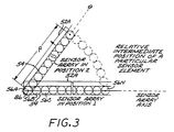
- FIG. 3 illustrates a simplified sensor array with a plurality of sensor elements for the sensor head of the scanning system of FIG. 1, in two positions relative to the surface of the flat medium.
- FIG. 4 is a simplified illustration of one exemplary path of the outermost sensor of the sensor array of FIG. 3 for a complete rotation (2 ⁇ radians) of the medium, for the case of a non-overlapped sensor array spiral.
- FIG. 5 is a simplified illustration of a first alternate path of the outermost sensor element of the sensor array of FIG. 3 for a complete rotation (2 ⁇ radians) of the medium, for the case of a partially-overlapped sensor array spiral.
- FIG. 6 is a simplified illustration of a second alternate path of the outermost sensor element of the sensor array of FIG. 3 for a complete rotation (2 ⁇ radians) of the medium, for the case of a partially-underlapped sensor array spiral.
- FIG. 7 is a graph of the angular speed of the flat medium as a function of radial distance for the embodiment of FIG. 2.
- FIG. 8 is a simplified schematic block diagram of the control system comprising the optical scanner system of FIG. 1.
- a technique of optical scanning involves providing relative motion between a flat medium bearing the image to be scanned and an array of light sensors along a spiral path, which preferably is the exact spiral path to be subsequently used in an ink-jet printing process.
- This scanning technique eliminates the need for any coordinate conversions whatsoever, and eliminates any printing artifacts introduced by such conversions or resampling when used with a printer designed for such data.
- the data produced may be easily re-sampled into commonly used rectangular coordinates using known techniques, such as a convolution technique.
- the spiral maximum diameter may be made equal to the diagonal dimension of a rectangular media, thus allowing information very close to or at the edges of the media to be captured, and so reducing the area of nonscanned margins to zero on both sides and the top and bottom of the media when it is subsequently rendered. Benefits resulting from uni-directional scanning and non start-stop motions of the scanning array will also reduce effects of mechanical hysteresis present in some scanning mechanisms.
- a spiral pattern of pixels so scanned in accordance with this aspect of this invention provides image data pixels located at physical media coordinates which may be exactly rendered or printed by a spiral printer whose nozzle arrays corre-spond in physical location to those of the array of light sensors comprising the light sensor array. This results from the characteristic of sensor arrays that pixels are sampled at some sample rate, and the sampling rate can be chosen in dependence on the firing rate of the ink jet printer nozzles.
- the spiral pattern can be accomplished, in one exemplary embodiment, by mounting the scanner array on an arm which radiates from a center of coordinates in RHO"- ( ⁇ ), THETA ( ⁇ ) coordinate space, where RHO is a measure of distance from a center of coordinates, and THETA is a measure of angle, most usually in radians.
- the scanner array can then be moved outward from this center, while at the same time the media may be rotated in a circle around the center of coordinates.
- the sensor array can be rotated and translated instead of the media to provide a spiral locus for the sensor elements relative to the print medium.
- FIGS. 1-8 illustrate an optical scanning system 50 which embodies this invention.
- An optical sensor head 52 is supported in a carriage 60.
- the sensor head includes a sensor array 54 comprising sensor elements 56A-56N, and an illumination source 52A (FIG. 3).
- An exemplary optical scanning head suitable for the purpose is described in European patent application EP-A-0831639.
- the carriage 60 is adapted for movement along a scan axis 62.
- a carriage drive system 70 is coupled to the carriage to drive the carriage in a path along the axis 62.
- the exemplary carriage drive system 70 includes a drive motor 72, belt drive 74, and encoder strip 76 with encoder sensor 78 (FIG. 4) for providing carriage position data.
- Other drive mechanisms can alternatively be employed, such as leadscrew drives.
- the medium 10 bearing the image to be scanned e.g. a sheet of a document, a drawing, or a photograph
- the turntable platen 80 is driven by a rotary turntable drive system 90 which includes a turnable motor 92 and a turntable encoder 94 (FIG. 8) for providing turntable position data.
- an apparatus for holding the medium 10 flat against the turntable platen 80.
- Such apparatus are well known in the art, e.g. a vacuum hold-down system, an electrostatic system, or a mechanical system with a fixture for holding the medium in place.
- the carriage axis 62 intersects the linear sensor array axis above the center of coordinates 86 (FIG. 3).
- a second device 40 held by the carriage can be an ink jet pen, so that the machine 50 is a multi-function machine capable of both optical scanning functions and ink jet printing function, e.g. as a copy machine for first scanning a document and then printing a copy. Motions of the carriage and the media turntable may be used to allow both devices to sweep over the same regions on the medium.
- the second device 40 is optional, and can be omitted for some applications requiring only an optical scanning function.
- FIG. 2 is a chart illustrating the relative motion path, a spiral locus, of the sensor array in relation to the medium 10 during a scanning operation in accordance with an aspect of the invention.
- LOCUS 1 is a trace of the path taken by the light sensor element of sensor array 54 which is mounted furthest from the center of coordinates 86, relative to the surface of the medium 10.
- REGION 1 is the circular region defined by the light sensor sweep which would occur with a stationary light sensor, when the center of the innermost light sensor is coincident vertically with the center of coordinates, such that the inner light sensor element is over the center of coordinates 86, and the light sensor element located at the position of LOCUS 1 is the furthest from this center.
- REGION 2 illustrates a rectangular scanning region, of dimensions W by H, of an exemplary rectangular image or document.
- REGION 3 is bounded by a circle indicating the outer limit of coverage for the spiral scanning process.
- FIG. 3 illustrates a simplified linear sensor array 54 with a plurality of sensor elements 56A.-56N and a linear illumination source 52A.
- the sensor array can provide monochromatic or color image data; both types of sensor heads are well known in the art.
- the illumination source can be an array of LEDs, and can include for full color applications red, blue and green LEDS. Typically, as is well known in the art, the illumination source is controlled by a controller to provide light flashes timed in accordance with the sampling of the sensor elements; however other illumination schemes may also be used.
- Position 1 shows the sensor array in a start position relative to the surface of the medium 10, with the sensor element 56A at the platen center of coordinates 86.
- Position 2 shows a relative rotation (by some angle ⁇ ) between the sensor array 54 and the medium 10.
- the carriage is stationary during the first complete rotation of the platen 80, to provide complete coverage, i.e. to sweep out, REGION 1 .
- This first complete relative rotation is circular, and the sensor element 56A remains at the center of coordinates 86, which is illustrated in FIG. 3.
- the carriage is put in motion, to provide a relative path as shown in FIG. 4.
- FIG. 2 also illustrates the condition that the radical motion of the light sensor array is constrained to linearly move one unit of distance for each 2 ⁇ radians (360 degrees) rotation of the media, where one unit of distance is equal to the maximum radial 'span' of the light sensor array.
- the spiral sweep does not overlap or underlap onto itself.
- REGION 1 In order to completely sample REGION 1 with potential light sensor events, when the light sensor array is located over REGION 1, it needs to maintain this position during one full revolution of the media, in order to completely scan this central region. Subsequently, as the light sensor array moves outward, all the remaining area of REGION 3 becomes the potential target of light sensor events, an event being the sampling of the light emanating from a particular RHO, THETA position on the media, that is, a sample of one pixel which is to subsequently be rendered by an ink-jet mechanism, as more particularly described in the co-pending application referenced above.
- REGION 3 is circular, but most of the common media which it is desired to scan and sample digitally is rectangular, as indicated by REGION 2. In order to completely cover this rectangular region, the innermost light sensor element of the light sensor array needs to travel from the center of coordinates outward, and the outermost sensor element must be able to just reach the furthest corners of the media.
- FIG. 4 is a simplified illustration of the path of the outermost sensor element 56N for a second complete rotation (2 ⁇ radians) of the medium 10, i.e. for the case of a given motion of the carriage along the carriage axis 62 as the platen 80 rotates.
- the printer controller is programmed to suppress collecting data from the overlapped sensor elements, for this second rotation, over the overlapped area to prevent duplicate pixel coverage.
- the sensed pixel elements are preferably spaced evenly along the spiral path in accordance with standard design practices.
- FIG. 5 illustrates an exemplary spiral locus for such an overlapped case.
- the carriage moves outwardly at a rate of .5 unit (sensor array width) per complete rotation of the sensor array.
- the sensor array can be moved more than a full sensor array width for each 2 ⁇ radian rotation of the medium 10, providing gaps in the sensor coverage as the sensor array moves outwardly.
- FIG. 6 illustrates an exemplary spiral locus for such an underlapped case.
- the carriage moves outwardly at a rate of 2 units (sensor array widths) per complete rotation of the sensor array.
- the light sensor elements sample pixels at a constant rate such that pixels are sampled at uniformly equal distances one from another along an axis, although it is not required by this invention.
- dTHETA/dt V/RHO, where RHO starts out as one unit sensor array width, and reaches (W 2 + H 2 ) 1/2 /2 at the point where full coverage of the media has occurred. Because RHO is a variable which occurs in the denominator position, this means the rotational velocity is a nonlinear function of the position of the light sensor array, if a constant tangential velocity of the array is desired.
- FIG. 7 is a graph plotting the angular speed of the head as a function of the radial distance from the center of coordinates.
- the maximum rotational rate of the media will be V radians per second, when the innermost light sensor element is located over the center cf rotation, and the minimum rotational velocity will be 2V/ (W 2 + H 2 ) 1/2 radians per second for a light sensor array of 1 unit length, or span.
- the total scan time can be approximated as the time it takes to sweep out the total circular area of REGION 3 at the constant rate of 10 square inches per second (the area swept out be the head in one second is the length of the light sensor array times the distance traveled in one second).
- FIG. 8 is a simplified schematic block diagram of the control system for the system illustrated in FIG. 1.
- a controller 100 is coupled to a memory 102 for storage of image data collected during a scan job.
- the controller generates the drive commands to the carriage scanning motor 72, which comprises the carriage drive, and receives position signals indicative of the carriage/sensor array position from carriage scanning encoder 78.
- the controller also generates turntable motor drive commands to control the turntable motor 92 which rotates the turntable platen, and receives encoder signals from the turntable encoder 94 to determine the position and angular velocity of the turntable platen.
- the controller thus can control the carriage drive to achieve a non-overlapping spiral locus of the sensor array with respect to the medium, or an overlapped spiral locus to prevent banding or other artifacts, or an underlapped locus to provide for other special scanning modes.
- Other exemplary scanning modes include skipping scanning (collecting data) on alternate rotations forming the spiral, and to reverse the direction of the carriage at the end, filling in the omitted pixel data in the alternate rotations.
- the controller also receives sensor data from the optical sensor array, and, in the event the system 50 includes a printing function, provides firing pulses to the pen 40 in dependence on the image to be generated and the position of the pen in relation to the center of coordinates.
- the image data can be stored in the memory 102, or transmitted to or received from a host computer 120.
- the controller also provides sampling control signals to the sensor elements 56A-56N of the array 54, and illumination source control signals to the illumination source 52A, in dependence on the scanning mode and the position of the sensor head 52 in relation to the center of coordi-nates.
- the image pixel data collected during the scanning process can be stored in the memory 102, or passed to a host computer 120.
- the controller can also set the sampling rates for the various sensor elements. While in many cases it is desirable to use a constant (maximum) sampling rate, for other jobs or applications, the controller can control the sampling rate to be non-constant over a particular scan job, or to use a slower constant sampling rate. Faster or slower sampling rates can be used to achieve higher or lower densities of pixel data in particular regions on the medium 10.
- Each sensor element in the sensor array 54 is at a different radial distance from the center of coordinates 86 than any other sensor element. The result of this is that sampling all sensor elements at a constant rate produces pixel spacing differences which will be readily apparent at small values of RHO, especially in REGION 1 of FIG. 2.
- the sensor element 56N (FIG. 3) at RHO furthest from the center of rotation must sample 300 times for every inch along the circumference. For a one inch sensor array, the circumference is 2 ⁇ inches.
- 1,885 pixels would actually be sampled if the sampling rate were to be the same as the outermost sensor element, and the pixels thus produced would be closer together than those produced by the outermost sensor element.
- pixels which have been sampled should not be re-sampled, and logic in the controller can easily determine which pixel is to be sampled by each sensor element, and sensor elements closer to the center of rotation can be sampled less frequently.
- the sensor element 56A when the sensor array has reached a RHO value of 2.0, after the second complete rotation of the medium, the sensor element 56A (closest to the center of rotation) is at a RHO value of 1.0, and will need to be sampled at one-half the rate of the outermost sensor element to maintain the same pixel spacing. Again, logic in the controller will adjust the sampling rate to not sample a pixel which has already been sampled once. However, it is desired to minimize total scan time by making the sensor element 56N, i.e. the outermost sensor element, sample at the maximum (constant) rate possible.
- the above-described embodiments are merely illustrative of the possible specific embodiments which may represent principles of the present invention.
- other arrangements can be employed to provide the desired relative motion between the sensor head and the medium to provide a spiral path.
- the sensor head can located on an arm mechanism which moves in a spiral path, with the medium located on a stationary platen.
- the sensor head can be located in a stationary position, and the medium located on a platen which provides the desired spiral movement locus.
- the motion of the sensor head has been described as commencing from a position at the center of coordinates and moving radially outwardly, the sensor head could alternatively be started at any other position, e.g., at the outermost position and spiraled inwardly to end at the center of coordinates.
- Other arrangements may readily be devised in accordance with these principles by those skilled in the art without departing from the scope of the invention.
Abstract
Description
- The present invention relates to optical scanning techniques for documents, and more particularly to a method for continuous unidirectional scanning which reduces mechanical hysteresis and reduces the area of unscanned media to zero by scanning along a spiral locus path. This method produces data which exactly matches the data requirements of a spiral path locus ink-jet printer.
- The present application is related to co-pending European patent application number , entitled "Ink Jet Printing" filed on even date and claiming priority from U.S. patent application 09/066,621.
- Conventional optical scanners employ linear array optical sensors, and an apparatus for providing relative motion between the document or image to be scanned and the linear array sensor. In a general sense, the image is scanned by producing a series of scans of a given swath width, which are then assembled or processed by a processor in a rectilinear, Cartesian sense to provide the scanned data representing the image or document.
- This invention improves upon the typical, rectilinear Cartesian document scan in such a way as to produce sampled information from printed, drawn or photographic media which exactly matches a method of ink-jet printing along a spiral path locus. This invention also provides a way to capture the information present on the media all the way to the edges of the scanned media the same as in flat-bed scanners, and results in a simpler mechanical structure for the scanner.
- In the above-mentioned co-pending application, a method is described which improves upon an ink-jet printing hysteresis problem, and an ink-jet printing margin problem. In this co-pending application, it is shown that, by printing in a uni-direc-tional manner along a spiral path, both of these printing problems are reduced or elimated. However, because document scanners typically scan information from text or photographic media in a raster or x-y Cartesian fashion, there then necessitates a re-sampling or conversion from rectangular coordinates to polar coordinates to effect the printing of the scanned data on a spiral path. It is realized that this conversion process could produce undesirable printing artifacts under some circumstances, and the purpose of this invention is to eliminate these arti-facts entirely. Also, in many non-flatbed scanners, mechanical constraints do not allow the scanning sensors to view documents all the way to the document edges; hence information may be lost during a conventional non-flatbed scanning process. This invention also can result in a simplification of the mechanism required to move and house the scanner, since the scanning array nay be mounted either in place of, or radially co-lineda with, an ink-jet printing nozzle array, thus providing a printer and a scanner, both of which share electrical and mechanical parts to a large extent.
- A method for optically scanning a flat image is provided in accordance with one aspect of the invention. The method includes a sequence of the following steps;
- providing an optical sensor array ;
- supporting a flat medium to be optically scanned by the sensor array during a scanning cycle;
- providing relative motion between the sensor array and the medium such that a spiral locus is defined by the sensor array relative to the media during an optical scanning cycle; and
- collecting sensor data representing the image during the optical scanning cycle.
- In a preferred embodiment, the step of providing relative motion is accomplished without causing the sensor array to stop and reverse its direction periodically during the scanning cycle.
- In a further aspect of the invention, an optical scanning system comprises an optical sensor array comprising a plurality of sensor elements for collecting image data during an optical scanning cycle. A flat medium is positioned relative to the sensor array to permit optical sensing of an image carried by the flat medium during an optical scanning cycle. A relative, motion apparatus provides relative motion between the sensor array and the medium such that a spiral locus is defined by the sensor array relative to the media during an optical scanning cycle.
- The scanning system can further include, in a multi-function system, an ink jet pen having a nozzle array, and apparatus for providing relative motion between the nozzle array and the medium such that a spiral locus is defined by the nozzle array relative to a flat print medium during an ink jet printing cycle.
- These and other features and advantages of the present invention will become more apparent from the following detailed description of an exemplary embodiment thereof, as illustrated in the accompanying drawings, in which:
- FIG. 1 is a diagrammatic isometric view of an exemplary embodiment of an optical scanning system embodying the present invention.
- FIG. 2 is a graphical illustration of the spiral locus path of the relative motion between the optical sensor array and the flat medium, in accordance with an aspect of the invention.
- FIG. 3 illustrates a simplified sensor array with a plurality of sensor elements for the sensor head of the scanning system of FIG. 1, in two positions relative to the surface of the flat medium.
- FIG. 4 is a simplified illustration of one exemplary path of the outermost sensor of the sensor array of FIG. 3 for a complete rotation (2π radians) of the medium, for the case of a non-overlapped sensor array spiral.
- FIG. 5 is a simplified illustration of a first alternate path of the outermost sensor element of the sensor array of FIG. 3 for a complete rotation (2π radians) of the medium, for the case of a partially-overlapped sensor array spiral.
- FIG. 6 is a simplified illustration of a second alternate path of the outermost sensor element of the sensor array of FIG. 3 for a complete rotation (2π radians) of the medium, for the case of a partially-underlapped sensor array spiral.
- FIG. 7 is a graph of the angular speed of the flat medium as a function of radial distance for the embodiment of FIG. 2.
- FIG. 8 is a simplified schematic block diagram of the control system comprising the optical scanner system of FIG. 1.
- In accordance with an aspect of the invention, a technique of optical scanning involves providing relative motion between a flat medium bearing the image to be scanned and an array of light sensors along a spiral path, which preferably is the exact spiral path to be subsequently used in an ink-jet printing process. This scanning technique eliminates the need for any coordinate conversions whatsoever, and eliminates any printing artifacts introduced by such conversions or resampling when used with a printer designed for such data. Alternatively, the data produced may be easily re-sampled into commonly used rectangular coordinates using known techniques, such as a convolution technique.
- Additionally, the spiral maximum diameter may be made equal to the diagonal dimension of a rectangular media, thus allowing information very close to or at the edges of the media to be captured, and so reducing the area of nonscanned margins to zero on both sides and the top and bottom of the media when it is subsequently rendered. Benefits resulting from uni-directional scanning and non start-stop motions of the scanning array will also reduce effects of mechanical hysteresis present in some scanning mechanisms.
- What is desired is to provide relative motion between a light sensor array and a flat media, without actually causing the light sensor array or media to stop and reverse direction periodically, and, according to a further aspect of the invention, to cause the information so scanned to match, in a one-to-one correspondence, that information subsequently required by an ink-jet rendering process. A spiral pattern of pixels so scanned in accordance with this aspect of this invention provides image data pixels located at physical media coordinates which may be exactly rendered or printed by a spiral printer whose nozzle arrays corre-spond in physical location to those of the array of light sensors comprising the light sensor array. This results from the characteristic of sensor arrays that pixels are sampled at some sample rate, and the sampling rate can be chosen in dependence on the firing rate of the ink jet printer nozzles.
- The spiral pattern can be accomplished, in one exemplary embodiment, by mounting the scanner array on an arm which radiates from a center of coordinates in RHO"- (ρ), THETA (θ) coordinate space, where RHO is a measure of distance from a center of coordinates, and THETA is a measure of angle, most usually in radians. The scanner array can then be moved outward from this center, while at the same time the media may be rotated in a circle around the center of coordinates. Alternatively, the sensor array can be rotated and translated instead of the media to provide a spiral locus for the sensor elements relative to the print medium.
- FIGS. 1-8 illustrate an
optical scanning system 50 which embodies this invention. Anoptical sensor head 52 is supported in acarriage 60. The sensor head includes asensor array 54 comprisingsensor elements 56A-56N, and anillumination source 52A (FIG. 3). An exemplary optical scanning head suitable for the purpose is described in European patent application EP-A-0831639. - The
carriage 60 is adapted for movement along ascan axis 62. Acarriage drive system 70 is coupled to the carriage to drive the carriage in a path along theaxis 62. The exemplarycarriage drive system 70 includes adrive motor 72,belt drive 74, andencoder strip 76 with encoder sensor 78 (FIG. 4) for providing carriage position data. Other drive mechanisms can alternatively be employed, such as leadscrew drives. - The
medium 10 bearing the image to be scanned, e.g. a sheet of a document, a drawing, or a photograph, is supported on aflat turntable platen 80 which is in turn mounted for rotation about a center axis 82, which at the plane ofmedium 10 defines the center ofcoordinates 86. Theturntable platen 80 is driven by a rotaryturntable drive system 90 which includes aturnable motor 92 and a turntable encoder 94 (FIG. 8) for providing turntable position data. - In an exemplary embodiment, an apparatus is provided for holding the
medium 10 flat against theturntable platen 80. Such apparatus are well known in the art, e.g. a vacuum hold-down system, an electrostatic system, or a mechanical system with a fixture for holding the medium in place. - The
carriage axis 62 intersects the linear sensor array axis above the center of coordinates 86 (FIG. 3). - Also shown in FIG. 1 is a
second device 40 held by the carriage. This device can be an ink jet pen, so that themachine 50 is a multi-function machine capable of both optical scanning functions and ink jet printing function, e.g. as a copy machine for first scanning a document and then printing a copy. Motions of the carriage and the media turntable may be used to allow both devices to sweep over the same regions on the medium. Thesecond device 40 is optional, and can be omitted for some applications requiring only an optical scanning function. - FIG. 2 is a chart illustrating the relative motion path, a spiral locus, of the sensor array in relation to the
medium 10 during a scanning operation in accordance with an aspect of the invention. LOCUS 1 is a trace of the path taken by the light sensor element ofsensor array 54 which is mounted furthest from the center ofcoordinates 86, relative to the surface of themedium 10. REGION 1 is the circular region defined by the light sensor sweep which would occur with a stationary light sensor, when the center of the innermost light sensor is coincident vertically with the center of coordinates, such that the inner light sensor element is over the center ofcoordinates 86, and the light sensor element located at the position of LOCUS 1 is the furthest from this center.REGION 2 illustrates a rectangular scanning region, of dimensions W by H, of an exemplary rectangular image or document.REGION 3 is bounded by a circle indicating the outer limit of coverage for the spiral scanning process. - FIG. 3 illustrates a simplified
linear sensor array 54 with a plurality of sensor elements 56A.-56N and alinear illumination source 52A. The sensor array can provide monochromatic or color image data; both types of sensor heads are well known in the art. The illumination source can be an array of LEDs, and can include for full color applications red, blue and green LEDS. Typically, as is well known in the art, the illumination source is controlled by a controller to provide light flashes timed in accordance with the sampling of the sensor elements; however other illumination schemes may also be used.Position 1 shows the sensor array in a start position relative to the surface of the medium 10, with thesensor element 56A at the platen center ofcoordinates 86.Position 2 shows a relative rotation (by some angle θ) between thesensor array 54 and the medium 10. In this exemplary embodiment, the carriage is stationary during the first complete rotation of theplaten 80, to provide complete coverage, i.e. to sweep out,REGION 1 . This first complete relative rotation is circular, and thesensor element 56A remains at the center ofcoordinates 86, which is illustrated in FIG. 3. On the second rotation, the carriage is put in motion, to provide a relative path as shown in FIG. 4. - FIG. 2 also illustrates the condition that the radical motion of the light sensor array is constrained to linearly move one unit of distance for each 2π radians (360 degrees) rotation of the media, where one unit of distance is equal to the maximum radial 'span' of the light sensor array. Thus, in FIG. 2, the spiral sweep does not overlap or underlap onto itself. For the third and all subsequent rotations of the
platen 30, there will be no overlapped coverage of the sensor array relative to earlier rotations/passes of the sensor array. - In order to completely sample
REGION 1 with potential light sensor events, when the light sensor array is located overREGION 1, it needs to maintain this position during one full revolution of the media, in order to completely scan this central region. Subsequently, as the light sensor array moves outward, all the remaining area ofREGION 3 becomes the potential target of light sensor events, an event being the sampling of the light emanating from a particular RHO, THETA position on the media, that is, a sample of one pixel which is to subsequently be rendered by an ink-jet mechanism, as more particularly described in the co-pending application referenced above.REGION 3 is circular, but most of the common media which it is desired to scan and sample digitally is rectangular, as indicated byREGION 2. In order to completely cover this rectangular region, the innermost light sensor element of the light sensor array needs to travel from the center of coordinates outward, and the outermost sensor element must be able to just reach the furthest corners of the media. - FIG. 4 is a simplified illustration of the path of the
outermost sensor element 56N for a second complete rotation (2π radians) of the medium 10, i.e. for the case of a given motion of the carriage along thecarriage axis 62 as theplaten 80 rotates. The path starts at position A of thesensor element 56N, at θ = 0, radius ρ = 1 unit (equal to the width of the sensor array), and ends at position E of thesensor element 56N, at θ = 2π, ρ = 2 units. Thesensor element 56N follows through the path illustrated relative to the medium, with position B occurring at θ= π/2, ρ = 1.25 unit, position C occuring at θ = π , ρ = 1.5 unit, and position D occurring at θ = 3π/2, ρ = 1,75 units. During this second complete rotation, i.e. the first rotation after the carriage is put into motion, there will be overlapped coverage of sensor elements with respect to the initial rotation withinREGION 1. Preferably, the printer controller is programmed to suppress collecting data from the overlapped sensor elements, for this second rotation, over the overlapped area to prevent duplicate pixel coverage. Also, the sensed pixel elements are preferably spaced evenly along the spiral path in accordance with standard design practices. - In many applications it may be desirable to overlap the path to prevent spiral banding, just as is presently done to prevent swath banding in known rectangular coordinate scanners by averaging several samples at the same pixel (ρ,θ) coordinate. In this case, then, the sensor array will be moved less than a full sensor array width (1 unit) for each 2π radians rotation of the medium 10. FIG. 5 illustrates an exemplary spiral locus for such an overlapped case. In this example, the carriage moves outwardly at a rate of .5 unit (sensor array width) per complete rotation of the sensor array. Alternatively, the sensor array can be moved more than a full sensor array width for each 2π radian rotation of the medium 10, providing gaps in the sensor coverage as the sensor array moves outwardly. These gaps can be filled in on a reverse spiral scan, moving the sensor array from an outside position back to the start position shown in FIG. 3. FIG. 6 illustrates an exemplary spiral locus for such an underlapped case. In this example, the carriage moves outwardly at a rate of 2 units (sensor array widths) per complete rotation of the sensor array.
- In many scanning cases, the light sensor elements sample pixels at a constant rate such that pixels are sampled at uniformly equal distances one from another along an axis, although it is not required by this invention. However, if this is a desired operation, then since the relative velocity of a given sensor element along the spiral will increase with radius RHO for a constant rotational speed, the circular rotational velocity of
platen 80 can be adjusted such that if S is a tangential distance alongLOCUS 1, and [1] dS = RHO∗dTHETA using 'd' to indicate "differential" as in calculus notation, then if t stands for time, [2] dS/dt = RHO * dTHETA/dt = V, where V is the desired constant velocity alongLCCUS 1. Solving [3] dTHETA/dt = V/RHO, where RHO starts out as one unit sensor array width, and reaches (W2 + H2)1/2/2 at the point where full coverage of the media has occurred. Because RHO is a variable which occurs in the denominator position, this means the rotational velocity is a nonlinear function of the position of the light sensor array, if a constant tangential velocity of the array is desired. FIG. 7 is a graph plotting the angular speed of the head as a function of the radial distance from the center of coordinates. - Put another way, the maximum rotational rate of the media will be V radians per second, when the innermost light sensor element is located over the center cf rotation, and the minimum rotational velocity will be 2V/ (W2 + H2) 1/2 radians per second for a light sensor array of 1 unit length, or span.
- By way of illustrative example, assume that it is desired to sample, or scan, edge-to-edge on an 8.5 x 11 inch media using a light sensor array which consists of 300 light sensors elements, each of which is spaced equally from its neighbors by 1/300th of an inch. This array then is 1.0 inches long. Suppose further that the maximum tangential velocity that this head supports, while sampling pixels at its maximum rate, is 10.0 inches per second. Thus, 10*300=3000 light samples are taken per second while the array moves over the media at this speed, and the "swath-width" is 1.0 inch wide.
- The maximum position the light sensor element furthest from the center of rotation needs to be away from this center, for this example, is (W2 - H2) 1/2 /2 = (8.52112)1/2/2 = 6.95 inches. When this light sensor element reaches this outer limit of RHO its rotational velocity will be dTHETA/dt = V/RHO = 10.0 inches per-second/6.95 inches = 1.44 radians per second, or about 13.75 RPM (rotations per minute) as in FIG. 7. The tangential velocity is the rotational velocity times the radius, which is 1.44*6.95 = 10 inches per second, as expected. Now when the light sensor element furthest from the center of rotation is at RHO = 1.0 inch, the rotational velocity is 10.0 inches-per-second/1.0 inches = 10.0 radian-per-second, or about 95.5 RPM as in FIG. 7.
- The total scan time can be approximated as the time it takes to sweep out the total circular area of
REGION 3 at the constant rate of 10 square inches per second (the area swept out be the head in one second is the length of the light sensor array times the distance traveled in one second). The "swept out" circular area is π(RADIUS)2 = 3.14159*(6.95)2 = 151.75 square inches. At 10 square inches per second, this is about 15.2 seconds. - FIG. 8 is a simplified schematic block diagram of the control system for the system illustrated in FIG. 1. A
controller 100 is coupled to amemory 102 for storage of image data collected during a scan job. The controller generates the drive commands to thecarriage scanning motor 72, which comprises the carriage drive, and receives position signals indicative of the carriage/sensor array position from carriage scanning encoder 78. The controller also generates turntable motor drive commands to control theturntable motor 92 which rotates the turntable platen, and receives encoder signals from theturntable encoder 94 to determine the position and angular velocity of the turntable platen. The controller thus can control the carriage drive to achieve a non-overlapping spiral locus of the sensor array with respect to the medium, or an overlapped spiral locus to prevent banding or other artifacts, or an underlapped locus to provide for other special scanning modes. Other exemplary scanning modes include skipping scanning (collecting data) on alternate rotations forming the spiral, and to reverse the direction of the carriage at the end, filling in the omitted pixel data in the alternate rotations. - The controller also receives sensor data from the optical sensor array, and, in the event the
system 50 includes a printing function, provides firing pulses to thepen 40 in dependence on the image to be generated and the position of the pen in relation to the center of coordinates. The image data can be stored in thememory 102, or transmitted to or received from ahost computer 120. - The controller also provides sampling control signals to the
sensor elements 56A-56N of thearray 54, and illumination source control signals to theillumination source 52A, in dependence on the scanning mode and the position of thesensor head 52 in relation to the center of coordi-nates. The image pixel data collected during the scanning process can be stored in thememory 102, or passed to ahost computer 120. The controller can also set the sampling rates for the various sensor elements. While in many cases it is desirable to use a constant (maximum) sampling rate, for other jobs or applications, the controller can control the sampling rate to be non-constant over a particular scan job, or to use a slower constant sampling rate. Faster or slower sampling rates can be used to achieve higher or lower densities of pixel data in particular regions on the medium 10. - Each sensor element in the
sensor array 54 is at a different radial distance from the center ofcoordinates 86 than any other sensor element. The result of this is that sampling all sensor elements at a constant rate produces pixel spacing differences which will be readily apparent at small values of RHO, especially inREGION 1 of FIG. 2. For example, inREGION 1 during the initial rotation of the media (which is not accompanied by a radial motion of the carriage), and for a 1/300th inch sensor element spacing, thesensor element 56N (FIG. 3) at RHO furthest from the center of rotation must sample 300 times for every inch along the circumference. For a one inch sensor array, the circumference is 2π inches. Hence there will be 1,885 pixels sampled at a spacing of 1/300th of an inch along this circumference. At thesecond nozzle 56B out from the center of coordinates, the circumference is only 2π/300 inches, or .0209 inch, and collecting 1,885 image pixels along this circular path is incorrect because it will produce too many pixels along that circular path. At the sensor element next to the outermost sensor element, i.e. 1/300 inch closer to the center of rotation thansensor element 56N, the number of pixels sampled to maintain 300 pixels per inch should be 2π(1.0-1/300)(300), which is 1,879. Instead, however, 1,885 pixels would actually be sampled if the sampling rate were to be the same as the outermost sensor element, and the pixels thus produced would be closer together than those produced by the outermost sensor element. During the sweep ofREGION 1, or at any other region of the medium, pixels which have been sampled should not be re-sampled, and logic in the controller can easily determine which pixel is to be sampled by each sensor element, and sensor elements closer to the center of rotation can be sampled less frequently. - As a further example, when the sensor array has reached a RHO value of 2.0, after the second complete rotation of the medium, the
sensor element 56A (closest to the center of rotation) is at a RHO value of 1.0, and will need to be sampled at one-half the rate of the outermost sensor element to maintain the same pixel spacing. Again, logic in the controller will adjust the sampling rate to not sample a pixel which has already been sampled once. However, it is desired to minimize total scan time by making thesensor element 56N, i.e. the outermost sensor element, sample at the maximum (constant) rate possible. FIG. 7 shows the relationship between the constant (maximum) rate of this outermost sensor element, while all other sensor elements will actually be sampled when the pixel over which they are to sample is at least 1/300th of an inch away from any adjacent pixel, and this will always be at a lower rate of sampling than the maximum possible. These differences in rate rapidly diminish with distance from the center of rotation. - It is understood that the above-described embodiments are merely illustrative of the possible specific embodiments which may represent principles of the present invention. For example, other arrangements can be employed to provide the desired relative motion between the sensor head and the medium to provide a spiral path. For example, the sensor head can located on an arm mechanism which moves in a spiral path, with the medium located on a stationary platen. Or conversely, the sensor head can be located in a stationary position, and the medium located on a platen which provides the desired spiral movement locus. Also, while the motion of the sensor head has been described as commencing from a position at the center of coordinates and moving radially outwardly, the sensor head could alternatively be started at any other position, e.g., at the outermost position and spiraled inwardly to end at the center of coordinates. Other arrangements may readily be devised in accordance with these principles by those skilled in the art without departing from the scope of the invention.
Claims (17)
- A method for optically scanning a flat image, comprising a sequence of the following steps;providing an optical sensor array (54) ;supporting a flat medium (10) to be optically scanned by the sensor array during a scanning cycle;providing relative motion between the sensor array and the medium such that a spiral locus is defined by the sensor array relative to the media during an optical scanning cycle; andcollecting sensor data representing the image during the optical scanning cycle.
- A method according to Claim 1, further character-ized in that said step of providing relative motion is accomplished without causing the sensor array (54) to stop and reverse its direction periodically during the scanning cycle.
- A method according to Claim 1 or Claim 2, further characterized in that said sensor array (54) is mounted on an arm which radiates from a center of coordinates, and wherein said step of providing relative motion includes moving the sensor array outwardly on the arm from the center of coordinates while rotating the medium about the center of coordinates.
- A method according to Claim 3, further characterized in that the sensor array (54) spans a first distance in a direction extending radially from the center of coordinates, and said step of providing relative motion includes moving the sensor array radially at a rate such that the sensor array is moved radially by a distance equal to the first distance for each complete rotation of the medium (10) about the center of coordinates.
- A method according to Claim 3, further characterized in that the sensor array (54) spans a first distance in a direction extending radially from the center of coordinates, and said step of providing relative motion includes moving the sensor array radially at a rate such that the sensor array is moved radially by a distance which is less than the first distance for each complete rotation of the medium (10) about the center of coordinates.
- A method according to any preceding claim, further characterized in that the sensor array (54) includes a plurality of sensor elements (56A-56N) including an outermost sensor (56N) relative to the center of coordinates, and the step of collecting sensor data includes sampling the sensor elements at a constant rate, and the step of providing relative motion includes varying the rotation rate of the medium to achieve a substantially constant tangential velocity of the outermost sensor element of the sensor array.
- A method according to any of Claims 1-3, further characterized in that said step of providing relative motion between the sensor array (54) and the medium (10) includes moving the sensor array radially at a rate selected to provide a partial overlap of the sensor array relative to the medium during the scanning cycle.
- A method according to any of Claims 1-3 further characterized in that said step of providing relative motion between the sensor array (54) and the medium (10) includes moving the sensor array radially at a rate selected to provide a partial underlap of the sensor array relative to the medium.
- A method according to any preceding claim, further characterized in that the step of providing relative movement includes moving the sensor array radially by a distance which is large enough to provide swept coverage of the sensor array (54) over the entire area of the medium (10) .
- An optical scanning system (50), comprising:an optical sensor array (54) comprising a plurality of sensor elements (56A-56N) for collecting image data during an optical scanning cycle;a flat medium (10) positioned relative to the sensor array to permit optical sensing of an image carried by the flat medium during an optical scanning cycle;apparatus (80,60, 72, 92) for providing relative motion between the sensor array and the medium such that a spiral locus is defined by the sensor array a relative to the media during an optical scanning cycle.
- A scanning system according to Claim 10 further characterized in that said apparatus (80,60, 72, 92) for providing relative motion between the sensor array (5.4) and the medium (10) is adapted to move the sensor array radial-ly at a rate which provides a partial overlap of the sensor array relative to the medium during the scanning cycle.
- A scanning system according to Claim 10 further characterized in that said apparatus (80,60, 72, 92) for providing relative motion between the sensor array (54) and the medium (10) is adapted to move the sensor array radially at a rate which provides a partial underlap of the sensor array relative to the medium.
- A scanning system according to any of Claims 10-12, further characterized by:a carriage (60) for holding the sensor array, said carriage mounted for movement along a carriage axis (62) extending through an center of coordinates; andan arm structure for supporting the carriage for said movement along said carriage axis; andwherein said apparatus for providing relative motion includes a carriage drive apparatus (72) for moving the optical sensor array outwardly on the arm from the center of coordinates and a turntable drive (92) for rotating the medium about the center of coordinates.
- A scanning system according to Claim 13 further characterized in that the sensor array (54) spans a first distance in a direction extending radially from the center of coordinates, and said carriage drive apparatus (72) is adapted to move the sensor array radially at a rate such that the sensor array is moved radially by a distance equal to the first distance for each complete rotation of the medium about the center of coordinates.
- A sensor system according to any of Claims 10-14, further characterized by a controller (100) for generating sampling commands to cause said sensor array (54) to sample pixels from a given sensor element comprising the sensor array at a constant rate for the scanning cycle, and the apparatus (92) for rotating the medium is adapted to vary the rotation rate of the medium to achieve a substantially constant tangential velocity of the given sensor element.
- A scanning system according to any of Claims 1014 further characterized by a controller (100) for generating sampling commands to cause said sensor array (54) to sample image pixels at a varying rate for the scanning cycle.
- A scanning system according to any of Claims 1016, further characterized in that the system is part of a multi-function scanner/printer system, which includes:an ink jet pen (40) having a nozzle array;apparatus (72, 92) for providing relative motion between the nozzle array and the medium such that a spiral locus is defined by the nozzle array relative to a flat print medium during an ink jet printing cycle.
Applications Claiming Priority (2)
| Application Number | Priority Date | Filing Date | Title |
|---|---|---|---|
| US09/066,622 US6310691B2 (en) | 1998-04-24 | 1998-04-24 | Technique for scanning documents using a spiral path locus |
| US66622 | 1998-04-24 |
Publications (3)
| Publication Number | Publication Date |
|---|---|
| EP0952725A2 true EP0952725A2 (en) | 1999-10-27 |
| EP0952725A3 EP0952725A3 (en) | 2000-06-14 |
| EP0952725B1 EP0952725B1 (en) | 2004-07-28 |
Family
ID=22070665
Family Applications (1)
| Application Number | Title | Priority Date | Filing Date |
|---|---|---|---|
| EP99303073A Expired - Lifetime EP0952725B1 (en) | 1998-04-24 | 1999-04-21 | Optical scanning of documents |
Country Status (4)
| Country | Link |
|---|---|
| US (1) | US6310691B2 (en) |
| EP (1) | EP0952725B1 (en) |
| JP (1) | JP3539888B2 (en) |
| DE (1) | DE69918888T2 (en) |
Cited By (7)
| Publication number | Priority date | Publication date | Assignee | Title |
|---|---|---|---|---|
| FR2819134A1 (en) * | 2001-01-02 | 2002-07-05 | Gerard Jean Paul Popineau | Digital image digitisation process uses radial scanning method in place of linear scan for higher resolution |
| WO2002098669A1 (en) * | 2001-06-01 | 2002-12-12 | Elesys, Inc. | Low-profile ink head cartridge with integrated movement mechanism and service station |
| US6786563B1 (en) | 2001-04-18 | 2004-09-07 | Elesys, Inc. | Interleaving apparatus and methods for radial printing |
| US6910750B2 (en) | 2000-06-02 | 2005-06-28 | Elesys, Inc. | Low-profile ink head cartridge with integrated movement mechanism and service station |
| US6986559B1 (en) | 2001-04-20 | 2006-01-17 | Elesys, Inc. | Position information apparatus and methods for radial printing |
| US7284804B2 (en) | 2001-04-18 | 2007-10-23 | Elesys, Inc. | Interleaving apparatus and methods for radial printing |
| EP1938980A1 (en) * | 2006-12-27 | 2008-07-02 | Andrea Mayrhofer | Printing device and method for printing |
Families Citing this family (8)
| Publication number | Priority date | Publication date | Assignee | Title |
|---|---|---|---|---|
| US7307649B2 (en) * | 2002-12-12 | 2007-12-11 | Hewlett-Packard Development Company, L.P. | Optical disc non-cartesian coordinate system |
| US7433090B2 (en) * | 2003-01-28 | 2008-10-07 | Murray David K | Print/scan assembly and printer apparatus and methods including the same |
| US6896355B2 (en) | 2003-06-02 | 2005-05-24 | Hewlett-Packard Development Company, Lp. | Printhead positioning mechanism |
| US7426064B2 (en) * | 2003-12-08 | 2008-09-16 | Lexmark International, Inc | Scan bar and method for scanning an image |
| US7377617B2 (en) * | 2004-10-12 | 2008-05-27 | Clarke Leo C | Printing apparatus and method |
| CN107147854B (en) * | 2017-07-07 | 2023-08-29 | 合肥芯福科技有限公司 | Pixel scanning method and pixel array |
| CN108872372B (en) * | 2018-07-27 | 2020-02-07 | 爱德森(厦门)电子有限公司 | Eddy current imaging detection device for spot welding quality of metal plate |
| CN109001301B (en) * | 2018-07-27 | 2020-02-07 | 爱德森(厦门)电子有限公司 | Ultrasonic imaging detection device for spot welding quality of metal plate |
Citations (6)
| Publication number | Priority date | Publication date | Assignee | Title |
|---|---|---|---|---|
| DE3444089A1 (en) * | 1983-12-05 | 1985-09-26 | Lothar 5300 Bonn Becker | Small optoelectronic duplicating machine |
| US4609818A (en) * | 1982-12-24 | 1986-09-02 | International Business Machines Corporation | Opto-electronic scanning apparatus with rotary plate scanning element |
| JPS6490433A (en) * | 1987-09-30 | 1989-04-06 | Fuji Photo Film Co Ltd | Image reading and reproducing method |
| EP0337812A2 (en) * | 1988-04-15 | 1989-10-18 | The Mead Corporation | Method and apparatus for creating a photomask for projecting an image |
| US5317337A (en) * | 1987-07-01 | 1994-05-31 | U.S. Philips Corporation | Printing method for disc-shaped information carriers |
| JPH09265760A (en) * | 1996-03-27 | 1997-10-07 | Seiko Epson Corp | Optical disk device |
Family Cites Families (11)
| Publication number | Priority date | Publication date | Assignee | Title |
|---|---|---|---|---|
| US2389408A (en) | 1944-04-28 | 1945-11-20 | Albert W Boyd | Attachment for typewriting machines |
| GB1406482A (en) | 1972-01-14 | 1975-09-17 | Marconi Co Ltd | Teleprinters |
| NL7413162A (en) * | 1974-10-07 | 1976-04-09 | Philips Nv | DEVICE FOR READING A DISK-SHAPED RECORDING CARRIER. |
| US4069484A (en) * | 1976-05-28 | 1978-01-17 | Rca Corporation | Defect plotting system |
| US4410968A (en) * | 1977-03-24 | 1983-10-18 | Thomas Lee Siwecki | Method and apparatus for recording on a disk supported deformable metallic film |
| US4276561A (en) * | 1979-04-06 | 1981-06-30 | Jon Friedman | Earth photo globe |
| JPS6423137A (en) * | 1987-07-17 | 1989-01-25 | Canon Kk | Far field image measuring instrument for light emitting element |
| JP2523948B2 (en) * | 1990-06-11 | 1996-08-14 | 松下電器産業株式会社 | Pyroelectric infrared detector |
| US5589952A (en) * | 1994-03-18 | 1996-12-31 | Sony/Tektronix Corporation | Disc high resolution scanner |
| US5935331A (en) | 1994-09-09 | 1999-08-10 | Matsushita Electric Industrial Co., Ltd. | Apparatus and method for forming films |
| JPH09265860A (en) | 1996-03-27 | 1997-10-07 | Matsushita Electric Ind Co Ltd | Push-switch-equipped rotary electronic component |
-
1998
- 1998-04-24 US US09/066,622 patent/US6310691B2/en not_active Expired - Fee Related
-
1999
- 1999-04-21 DE DE69918888T patent/DE69918888T2/en not_active Expired - Fee Related
- 1999-04-21 EP EP99303073A patent/EP0952725B1/en not_active Expired - Lifetime
- 1999-04-26 JP JP11788099A patent/JP3539888B2/en not_active Expired - Fee Related
Patent Citations (6)
| Publication number | Priority date | Publication date | Assignee | Title |
|---|---|---|---|---|
| US4609818A (en) * | 1982-12-24 | 1986-09-02 | International Business Machines Corporation | Opto-electronic scanning apparatus with rotary plate scanning element |
| DE3444089A1 (en) * | 1983-12-05 | 1985-09-26 | Lothar 5300 Bonn Becker | Small optoelectronic duplicating machine |
| US5317337A (en) * | 1987-07-01 | 1994-05-31 | U.S. Philips Corporation | Printing method for disc-shaped information carriers |
| JPS6490433A (en) * | 1987-09-30 | 1989-04-06 | Fuji Photo Film Co Ltd | Image reading and reproducing method |
| EP0337812A2 (en) * | 1988-04-15 | 1989-10-18 | The Mead Corporation | Method and apparatus for creating a photomask for projecting an image |
| JPH09265760A (en) * | 1996-03-27 | 1997-10-07 | Seiko Epson Corp | Optical disk device |
Cited By (9)
| Publication number | Priority date | Publication date | Assignee | Title |
|---|---|---|---|---|
| US6910750B2 (en) | 2000-06-02 | 2005-06-28 | Elesys, Inc. | Low-profile ink head cartridge with integrated movement mechanism and service station |
| FR2819134A1 (en) * | 2001-01-02 | 2002-07-05 | Gerard Jean Paul Popineau | Digital image digitisation process uses radial scanning method in place of linear scan for higher resolution |
| US6786563B1 (en) | 2001-04-18 | 2004-09-07 | Elesys, Inc. | Interleaving apparatus and methods for radial printing |
| US7284804B2 (en) | 2001-04-18 | 2007-10-23 | Elesys, Inc. | Interleaving apparatus and methods for radial printing |
| US6986559B1 (en) | 2001-04-20 | 2006-01-17 | Elesys, Inc. | Position information apparatus and methods for radial printing |
| WO2002098669A1 (en) * | 2001-06-01 | 2002-12-12 | Elesys, Inc. | Low-profile ink head cartridge with integrated movement mechanism and service station |
| EP1938980A1 (en) * | 2006-12-27 | 2008-07-02 | Andrea Mayrhofer | Printing device and method for printing |
| WO2008083764A2 (en) * | 2006-12-27 | 2008-07-17 | Andrea Mayrhofer | Print device and method for printing |
| WO2008083764A3 (en) * | 2006-12-27 | 2008-11-27 | Andrea Mayrhofer | Print device and method for printing |
Also Published As
| Publication number | Publication date |
|---|---|
| DE69918888D1 (en) | 2004-09-02 |
| EP0952725B1 (en) | 2004-07-28 |
| US6310691B2 (en) | 2001-10-30 |
| DE69918888T2 (en) | 2005-07-28 |
| US20010013956A1 (en) | 2001-08-16 |
| JP2000028950A (en) | 2000-01-28 |
| JP3539888B2 (en) | 2004-07-07 |
| EP0952725A3 (en) | 2000-06-14 |
Similar Documents
| Publication | Publication Date | Title |
|---|---|---|
| US6386667B1 (en) | Technique for media coverage using ink jet writing technology | |
| EP0952725B1 (en) | Optical scanning of documents | |
| US5446559A (en) | Method and apparatus for scanning and printing | |
| EP0399651B1 (en) | Apparatus and method of scanning image data | |
| AU749967B2 (en) | Radial printing system and methods | |
| WO2004091917A1 (en) | Device, system, and method for discharging liquid | |
| US6353481B1 (en) | Technique for correcting printing errors in a shuttle type multifunctional apparatus | |
| EP0952003B1 (en) | Ink jet printing | |
| JPH05212924A (en) | Device and method for minimizing scanning error of printer | |
| US20080008384A1 (en) | Method For Rotational Media Printing | |
| JPS5980061A (en) | Method and device for picture scan recording | |
| JPH06109096A (en) | Low-speed scanning stitch mechanism | |
| US20050093960A1 (en) | Method for correcting skewed recording when exposing printing originals | |
| JPH0720196B2 (en) | Document scanning device | |
| US20040207711A1 (en) | Device for setting the focus of exposure heads of a printing plate exposer | |
| US20090026265A1 (en) | Determining a position of a print carriage | |
| US6115130A (en) | Method of recognizing printing region | |
| EP0983864A3 (en) | Method of controlling a printhead movement based on a lead screw pitch to minimize swath-to-swath error in an image processing apparatus | |
| JP2002067284A (en) | Medium coverage technology using ink jet writing technology | |
| JPS6236090Y2 (en) | ||
| JPH08119533A (en) | Sheet carrying device and image formation device | |
| US7559711B2 (en) | Method for controlling media feed in an imaging apparatus | |
| JP2003029352A (en) | Bi-directional flatbed scanning and automatic document feed and optical scanner | |
| JP3276680B2 (en) | Image processing device | |
| JP2002283549A (en) | Printer controller and method for controlling printer |
Legal Events
| Date | Code | Title | Description |
|---|---|---|---|
| PUAI | Public reference made under article 153(3) epc to a published international application that has entered the european phase |
Free format text: ORIGINAL CODE: 0009012 |
|
| AK | Designated contracting states |
Kind code of ref document: A2 Designated state(s): DE FR GB |
|
| AX | Request for extension of the european patent |
Free format text: AL;LT;LV;MK;RO;SI |
|
| PUAL | Search report despatched |
Free format text: ORIGINAL CODE: 0009013 |
|
| AK | Designated contracting states |
Kind code of ref document: A3 Designated state(s): AT BE CH CY DE DK ES FI FR GB GR IE IT LI LU MC NL PT SE |
|
| AX | Request for extension of the european patent |
Free format text: AL;LT;LV;MK;RO;SI |
|
| 17P | Request for examination filed |
Effective date: 20000807 |
|
| AKX | Designation fees paid |
Free format text: DE FR GB |
|
| RAP1 | Party data changed (applicant data changed or rights of an application transferred) |
Owner name: HEWLETT-PACKARD COMPANY, A DELAWARE CORPORATION |
|
| 17Q | First examination report despatched |
Effective date: 20020814 |
|
| GRAP | Despatch of communication of intention to grant a patent |
Free format text: ORIGINAL CODE: EPIDOSNIGR1 |
|
| GRAS | Grant fee paid |
Free format text: ORIGINAL CODE: EPIDOSNIGR3 |
|
| GRAA | (expected) grant |
Free format text: ORIGINAL CODE: 0009210 |
|
| RIN1 | Information on inventor provided before grant (corrected) |
Inventor name: CARIFFE, ALAN E. |
|
| AK | Designated contracting states |
Kind code of ref document: B1 Designated state(s): DE FR GB |
|
| REG | Reference to a national code |
Ref country code: GB Ref legal event code: FG4D |
|
| REF | Corresponds to: |
Ref document number: 69918888 Country of ref document: DE Date of ref document: 20040902 Kind code of ref document: P |
|
| PGFP | Annual fee paid to national office [announced via postgrant information from national office to epo] |
Ref country code: GB Payment date: 20050413 Year of fee payment: 7 |
|
| PGFP | Annual fee paid to national office [announced via postgrant information from national office to epo] |
Ref country code: FR Payment date: 20050418 Year of fee payment: 7 |
|
| ET | Fr: translation filed | ||
| PGFP | Annual fee paid to national office [announced via postgrant information from national office to epo] |
Ref country code: DE Payment date: 20050531 Year of fee payment: 7 |
|
| PLBE | No opposition filed within time limit |
Free format text: ORIGINAL CODE: 0009261 |
|
| STAA | Information on the status of an ep patent application or granted ep patent |
Free format text: STATUS: NO OPPOSITION FILED WITHIN TIME LIMIT |
|
| 26N | No opposition filed |
Effective date: 20050429 |
|
| PG25 | Lapsed in a contracting state [announced via postgrant information from national office to epo] |
Ref country code: GB Free format text: LAPSE BECAUSE OF NON-PAYMENT OF DUE FEES Effective date: 20060421 |
|
| PG25 | Lapsed in a contracting state [announced via postgrant information from national office to epo] |
Ref country code: DE Free format text: LAPSE BECAUSE OF NON-PAYMENT OF DUE FEES Effective date: 20061101 |
|
| GBPC | Gb: european patent ceased through non-payment of renewal fee |
Effective date: 20060421 |
|
| REG | Reference to a national code |
Ref country code: FR Ref legal event code: ST Effective date: 20061230 |
|
| PG25 | Lapsed in a contracting state [announced via postgrant information from national office to epo] |
Ref country code: FR Free format text: LAPSE BECAUSE OF NON-PAYMENT OF DUE FEES Effective date: 20060502 |