EP0949619B1 - Data reproduction apparatus - Google Patents
Data reproduction apparatus Download PDFInfo
- Publication number
- EP0949619B1 EP0949619B1 EP99108324A EP99108324A EP0949619B1 EP 0949619 B1 EP0949619 B1 EP 0949619B1 EP 99108324 A EP99108324 A EP 99108324A EP 99108324 A EP99108324 A EP 99108324A EP 0949619 B1 EP0949619 B1 EP 0949619B1
- Authority
- EP
- European Patent Office
- Prior art keywords
- data
- controller
- video
- audio
- stc
- Prior art date
- Legal status (The legal status is an assumption and is not a legal conclusion. Google has not performed a legal analysis and makes no representation as to the accuracy of the status listed.)
- Expired - Lifetime
Links
Images


Classifications
-
- H—ELECTRICITY
- H04—ELECTRIC COMMUNICATION TECHNIQUE
- H04N—PICTORIAL COMMUNICATION, e.g. TELEVISION
- H04N9/00—Details of colour television systems
- H04N9/79—Processing of colour television signals in connection with recording
- H04N9/80—Transformation of the television signal for recording, e.g. modulation, frequency changing; Inverse transformation for playback
- H04N9/804—Transformation of the television signal for recording, e.g. modulation, frequency changing; Inverse transformation for playback involving pulse code modulation of the colour picture signal components
- H04N9/8042—Transformation of the television signal for recording, e.g. modulation, frequency changing; Inverse transformation for playback involving pulse code modulation of the colour picture signal components involving data reduction
-
- G—PHYSICS
- G11—INFORMATION STORAGE
- G11B—INFORMATION STORAGE BASED ON RELATIVE MOVEMENT BETWEEN RECORD CARRIER AND TRANSDUCER
- G11B20/00—Signal processing not specific to the method of recording or reproducing; Circuits therefor
- G11B20/00007—Time or data compression or expansion
-
- G—PHYSICS
- G11—INFORMATION STORAGE
- G11B—INFORMATION STORAGE BASED ON RELATIVE MOVEMENT BETWEEN RECORD CARRIER AND TRANSDUCER
- G11B20/00—Signal processing not specific to the method of recording or reproducing; Circuits therefor
- G11B20/00086—Circuits for prevention of unauthorised reproduction or copying, e.g. piracy
- G11B20/00681—Circuits for prevention of unauthorised reproduction or copying, e.g. piracy involving measures which prevent a specific kind of data access
- G11B20/00695—Circuits for prevention of unauthorised reproduction or copying, e.g. piracy involving measures which prevent a specific kind of data access said measures preventing that data are read from the recording medium
-
- G—PHYSICS
- G11—INFORMATION STORAGE
- G11B—INFORMATION STORAGE BASED ON RELATIVE MOVEMENT BETWEEN RECORD CARRIER AND TRANSDUCER
- G11B20/00—Signal processing not specific to the method of recording or reproducing; Circuits therefor
- G11B20/10—Digital recording or reproducing
- G11B20/10527—Audio or video recording; Data buffering arrangements
-
- G—PHYSICS
- G11—INFORMATION STORAGE
- G11B—INFORMATION STORAGE BASED ON RELATIVE MOVEMENT BETWEEN RECORD CARRIER AND TRANSDUCER
- G11B20/00—Signal processing not specific to the method of recording or reproducing; Circuits therefor
- G11B20/10—Digital recording or reproducing
- G11B20/12—Formatting, e.g. arrangement of data block or words on the record carriers
- G11B20/1217—Formatting, e.g. arrangement of data block or words on the record carriers on discs
- G11B20/1251—Formatting, e.g. arrangement of data block or words on the record carriers on discs for continuous data, e.g. digitised analog information signals, pulse code modulated [PCM] data
-
- G—PHYSICS
- G11—INFORMATION STORAGE
- G11B—INFORMATION STORAGE BASED ON RELATIVE MOVEMENT BETWEEN RECORD CARRIER AND TRANSDUCER
- G11B20/00—Signal processing not specific to the method of recording or reproducing; Circuits therefor
- G11B20/10—Digital recording or reproducing
- G11B20/18—Error detection or correction; Testing, e.g. of drop-outs
- G11B20/1806—Pulse code modulation systems for audio signals
- G11B20/1809—Pulse code modulation systems for audio signals by interleaving
-
- G—PHYSICS
- G11—INFORMATION STORAGE
- G11B—INFORMATION STORAGE BASED ON RELATIVE MOVEMENT BETWEEN RECORD CARRIER AND TRANSDUCER
- G11B20/00—Signal processing not specific to the method of recording or reproducing; Circuits therefor
- G11B20/10—Digital recording or reproducing
- G11B20/18—Error detection or correction; Testing, e.g. of drop-outs
- G11B20/1816—Testing
-
- G—PHYSICS
- G11—INFORMATION STORAGE
- G11B—INFORMATION STORAGE BASED ON RELATIVE MOVEMENT BETWEEN RECORD CARRIER AND TRANSDUCER
- G11B20/00—Signal processing not specific to the method of recording or reproducing; Circuits therefor
- G11B20/10—Digital recording or reproducing
- G11B20/18—Error detection or correction; Testing, e.g. of drop-outs
- G11B20/1833—Error detection or correction; Testing, e.g. of drop-outs by adding special lists or symbols to the coded information
-
- G—PHYSICS
- G11—INFORMATION STORAGE
- G11B—INFORMATION STORAGE BASED ON RELATIVE MOVEMENT BETWEEN RECORD CARRIER AND TRANSDUCER
- G11B20/00—Signal processing not specific to the method of recording or reproducing; Circuits therefor
- G11B20/10—Digital recording or reproducing
- G11B20/18—Error detection or correction; Testing, e.g. of drop-outs
- G11B20/1866—Error detection or correction; Testing, e.g. of drop-outs by interleaving
-
- G—PHYSICS
- G11—INFORMATION STORAGE
- G11B—INFORMATION STORAGE BASED ON RELATIVE MOVEMENT BETWEEN RECORD CARRIER AND TRANSDUCER
- G11B27/00—Editing; Indexing; Addressing; Timing or synchronising; Monitoring; Measuring tape travel
- G11B27/10—Indexing; Addressing; Timing or synchronising; Measuring tape travel
- G11B27/102—Programmed access in sequence to addressed parts of tracks of operating record carriers
- G11B27/105—Programmed access in sequence to addressed parts of tracks of operating record carriers of operating discs
-
- G—PHYSICS
- G11—INFORMATION STORAGE
- G11B—INFORMATION STORAGE BASED ON RELATIVE MOVEMENT BETWEEN RECORD CARRIER AND TRANSDUCER
- G11B27/00—Editing; Indexing; Addressing; Timing or synchronising; Monitoring; Measuring tape travel
- G11B27/10—Indexing; Addressing; Timing or synchronising; Measuring tape travel
- G11B27/19—Indexing; Addressing; Timing or synchronising; Measuring tape travel by using information detectable on the record carrier
- G11B27/28—Indexing; Addressing; Timing or synchronising; Measuring tape travel by using information detectable on the record carrier by using information signals recorded by the same method as the main recording
- G11B27/30—Indexing; Addressing; Timing or synchronising; Measuring tape travel by using information detectable on the record carrier by using information signals recorded by the same method as the main recording on the same track as the main recording
- G11B27/3027—Indexing; Addressing; Timing or synchronising; Measuring tape travel by using information detectable on the record carrier by using information signals recorded by the same method as the main recording on the same track as the main recording used signal is digitally coded
- G11B27/3036—Time code signal
-
- G—PHYSICS
- G11—INFORMATION STORAGE
- G11B—INFORMATION STORAGE BASED ON RELATIVE MOVEMENT BETWEEN RECORD CARRIER AND TRANSDUCER
- G11B27/00—Editing; Indexing; Addressing; Timing or synchronising; Monitoring; Measuring tape travel
- G11B27/10—Indexing; Addressing; Timing or synchronising; Measuring tape travel
- G11B27/19—Indexing; Addressing; Timing or synchronising; Measuring tape travel by using information detectable on the record carrier
- G11B27/28—Indexing; Addressing; Timing or synchronising; Measuring tape travel by using information detectable on the record carrier by using information signals recorded by the same method as the main recording
- G11B27/30—Indexing; Addressing; Timing or synchronising; Measuring tape travel by using information detectable on the record carrier by using information signals recorded by the same method as the main recording on the same track as the main recording
- G11B27/3027—Indexing; Addressing; Timing or synchronising; Measuring tape travel by using information detectable on the record carrier by using information signals recorded by the same method as the main recording on the same track as the main recording used signal is digitally coded
- G11B27/3063—Subcodes
-
- G—PHYSICS
- G11—INFORMATION STORAGE
- G11B—INFORMATION STORAGE BASED ON RELATIVE MOVEMENT BETWEEN RECORD CARRIER AND TRANSDUCER
- G11B27/00—Editing; Indexing; Addressing; Timing or synchronising; Monitoring; Measuring tape travel
- G11B27/10—Indexing; Addressing; Timing or synchronising; Measuring tape travel
- G11B27/19—Indexing; Addressing; Timing or synchronising; Measuring tape travel by using information detectable on the record carrier
- G11B27/28—Indexing; Addressing; Timing or synchronising; Measuring tape travel by using information detectable on the record carrier by using information signals recorded by the same method as the main recording
- G11B27/32—Indexing; Addressing; Timing or synchronising; Measuring tape travel by using information detectable on the record carrier by using information signals recorded by the same method as the main recording on separate auxiliary tracks of the same or an auxiliary record carrier
- G11B27/327—Table of contents
- G11B27/329—Table of contents on a disc [VTOC]
-
- G—PHYSICS
- G11—INFORMATION STORAGE
- G11B—INFORMATION STORAGE BASED ON RELATIVE MOVEMENT BETWEEN RECORD CARRIER AND TRANSDUCER
- G11B27/00—Editing; Indexing; Addressing; Timing or synchronising; Monitoring; Measuring tape travel
- G11B27/36—Monitoring, i.e. supervising the progress of recording or reproducing
-
- H—ELECTRICITY
- H04—ELECTRIC COMMUNICATION TECHNIQUE
- H04N—PICTORIAL COMMUNICATION, e.g. TELEVISION
- H04N5/00—Details of television systems
- H04N5/76—Television signal recording
- H04N5/91—Television signal processing therefor
- H04N5/92—Transformation of the television signal for recording, e.g. modulation, frequency changing; Inverse transformation for playback
- H04N5/9201—Transformation of the television signal for recording, e.g. modulation, frequency changing; Inverse transformation for playback involving the multiplexing of an additional signal and the video signal
- H04N5/9206—Transformation of the television signal for recording, e.g. modulation, frequency changing; Inverse transformation for playback involving the multiplexing of an additional signal and the video signal the additional signal being a character code signal
-
- H—ELECTRICITY
- H04—ELECTRIC COMMUNICATION TECHNIQUE
- H04N—PICTORIAL COMMUNICATION, e.g. TELEVISION
- H04N5/00—Details of television systems
- H04N5/76—Television signal recording
- H04N5/91—Television signal processing therefor
- H04N5/92—Transformation of the television signal for recording, e.g. modulation, frequency changing; Inverse transformation for playback
- H04N5/926—Transformation of the television signal for recording, e.g. modulation, frequency changing; Inverse transformation for playback by pulse code modulation
- H04N5/9261—Transformation of the television signal for recording, e.g. modulation, frequency changing; Inverse transformation for playback by pulse code modulation involving data reduction
-
- H—ELECTRICITY
- H04—ELECTRIC COMMUNICATION TECHNIQUE
- H04N—PICTORIAL COMMUNICATION, e.g. TELEVISION
- H04N5/00—Details of television systems
- H04N5/76—Television signal recording
- H04N5/91—Television signal processing therefor
- H04N5/93—Regeneration of the television signal or of selected parts thereof
- H04N5/937—Regeneration of the television signal or of selected parts thereof by assembling picture element blocks in an intermediate store
-
- G—PHYSICS
- G11—INFORMATION STORAGE
- G11B—INFORMATION STORAGE BASED ON RELATIVE MOVEMENT BETWEEN RECORD CARRIER AND TRANSDUCER
- G11B20/00—Signal processing not specific to the method of recording or reproducing; Circuits therefor
- G11B20/10—Digital recording or reproducing
- G11B20/12—Formatting, e.g. arrangement of data block or words on the record carriers
- G11B20/1217—Formatting, e.g. arrangement of data block or words on the record carriers on discs
- G11B2020/1218—Formatting, e.g. arrangement of data block or words on the record carriers on discs wherein the formatting concerns a specific area of the disc
- G11B2020/1232—Formatting, e.g. arrangement of data block or words on the record carriers on discs wherein the formatting concerns a specific area of the disc sector, i.e. the minimal addressable physical data unit
-
- G—PHYSICS
- G11—INFORMATION STORAGE
- G11B—INFORMATION STORAGE BASED ON RELATIVE MOVEMENT BETWEEN RECORD CARRIER AND TRANSDUCER
- G11B20/00—Signal processing not specific to the method of recording or reproducing; Circuits therefor
- G11B20/10—Digital recording or reproducing
- G11B20/12—Formatting, e.g. arrangement of data block or words on the record carriers
- G11B2020/1264—Formatting, e.g. arrangement of data block or words on the record carriers wherein the formatting concerns a specific kind of data
- G11B2020/1265—Control data, system data or management information, i.e. data used to access or process user data
- G11B2020/1285—Status of the record carrier, e.g. space bit maps, flags indicating a formatting status or a write permission
-
- G—PHYSICS
- G11—INFORMATION STORAGE
- G11B—INFORMATION STORAGE BASED ON RELATIVE MOVEMENT BETWEEN RECORD CARRIER AND TRANSDUCER
- G11B2220/00—Record carriers by type
- G11B2220/20—Disc-shaped record carriers
- G11B2220/21—Disc-shaped record carriers characterised in that the disc is of read-only, rewritable, or recordable type
- G11B2220/213—Read-only discs
-
- G—PHYSICS
- G11—INFORMATION STORAGE
- G11B—INFORMATION STORAGE BASED ON RELATIVE MOVEMENT BETWEEN RECORD CARRIER AND TRANSDUCER
- G11B2220/00—Record carriers by type
- G11B2220/20—Disc-shaped record carriers
- G11B2220/25—Disc-shaped record carriers characterised in that the disc is based on a specific recording technology
- G11B2220/2537—Optical discs
- G11B2220/2545—CDs
-
- G—PHYSICS
- G11—INFORMATION STORAGE
- G11B—INFORMATION STORAGE BASED ON RELATIVE MOVEMENT BETWEEN RECORD CARRIER AND TRANSDUCER
- G11B2220/00—Record carriers by type
- G11B2220/20—Disc-shaped record carriers
- G11B2220/25—Disc-shaped record carriers characterised in that the disc is based on a specific recording technology
- G11B2220/2537—Optical discs
- G11B2220/2562—DVDs [digital versatile discs]; Digital video discs; MMCDs; HDCDs
-
- G—PHYSICS
- G11—INFORMATION STORAGE
- G11B—INFORMATION STORAGE BASED ON RELATIVE MOVEMENT BETWEEN RECORD CARRIER AND TRANSDUCER
- G11B2220/00—Record carriers by type
- G11B2220/60—Solid state media
- G11B2220/65—Solid state media wherein solid state memory is used for storing indexing information or metadata
-
- G—PHYSICS
- G11—INFORMATION STORAGE
- G11B—INFORMATION STORAGE BASED ON RELATIVE MOVEMENT BETWEEN RECORD CARRIER AND TRANSDUCER
- G11B27/00—Editing; Indexing; Addressing; Timing or synchronising; Monitoring; Measuring tape travel
- G11B27/10—Indexing; Addressing; Timing or synchronising; Measuring tape travel
- G11B27/11—Indexing; Addressing; Timing or synchronising; Measuring tape travel by using information not detectable on the record carrier
-
- H—ELECTRICITY
- H04—ELECTRIC COMMUNICATION TECHNIQUE
- H04N—PICTORIAL COMMUNICATION, e.g. TELEVISION
- H04N5/00—Details of television systems
- H04N5/76—Television signal recording
- H04N5/78—Television signal recording using magnetic recording
- H04N5/782—Television signal recording using magnetic recording on tape
- H04N5/783—Adaptations for reproducing at a rate different from the recording rate
-
- H—ELECTRICITY
- H04—ELECTRIC COMMUNICATION TECHNIQUE
- H04N—PICTORIAL COMMUNICATION, e.g. TELEVISION
- H04N5/00—Details of television systems
- H04N5/76—Television signal recording
- H04N5/84—Television signal recording using optical recording
- H04N5/85—Television signal recording using optical recording on discs or drums
-
- H—ELECTRICITY
- H04—ELECTRIC COMMUNICATION TECHNIQUE
- H04N—PICTORIAL COMMUNICATION, e.g. TELEVISION
- H04N5/00—Details of television systems
- H04N5/76—Television signal recording
- H04N5/907—Television signal recording using static stores, e.g. storage tubes or semiconductor memories
-
- H—ELECTRICITY
- H04—ELECTRIC COMMUNICATION TECHNIQUE
- H04N—PICTORIAL COMMUNICATION, e.g. TELEVISION
- H04N9/00—Details of colour television systems
- H04N9/79—Processing of colour television signals in connection with recording
- H04N9/7921—Processing of colour television signals in connection with recording for more than one processing mode
-
- H—ELECTRICITY
- H04—ELECTRIC COMMUNICATION TECHNIQUE
- H04N—PICTORIAL COMMUNICATION, e.g. TELEVISION
- H04N9/00—Details of colour television systems
- H04N9/79—Processing of colour television signals in connection with recording
- H04N9/80—Transformation of the television signal for recording, e.g. modulation, frequency changing; Inverse transformation for playback
- H04N9/804—Transformation of the television signal for recording, e.g. modulation, frequency changing; Inverse transformation for playback involving pulse code modulation of the colour picture signal components
- H04N9/806—Transformation of the television signal for recording, e.g. modulation, frequency changing; Inverse transformation for playback involving pulse code modulation of the colour picture signal components with processing of the sound signal
- H04N9/8063—Transformation of the television signal for recording, e.g. modulation, frequency changing; Inverse transformation for playback involving pulse code modulation of the colour picture signal components with processing of the sound signal using time division multiplex of the PCM audio and PCM video signals
-
- H—ELECTRICITY
- H04—ELECTRIC COMMUNICATION TECHNIQUE
- H04N—PICTORIAL COMMUNICATION, e.g. TELEVISION
- H04N9/00—Details of colour television systems
- H04N9/79—Processing of colour television signals in connection with recording
- H04N9/80—Transformation of the television signal for recording, e.g. modulation, frequency changing; Inverse transformation for playback
- H04N9/82—Transformation of the television signal for recording, e.g. modulation, frequency changing; Inverse transformation for playback the individual colour picture signal components being recorded simultaneously only
- H04N9/8205—Transformation of the television signal for recording, e.g. modulation, frequency changing; Inverse transformation for playback the individual colour picture signal components being recorded simultaneously only involving the multiplexing of an additional signal and the colour video signal
- H04N9/8227—Transformation of the television signal for recording, e.g. modulation, frequency changing; Inverse transformation for playback the individual colour picture signal components being recorded simultaneously only involving the multiplexing of an additional signal and the colour video signal the additional signal being at least another television signal
-
- H—ELECTRICITY
- H04—ELECTRIC COMMUNICATION TECHNIQUE
- H04N—PICTORIAL COMMUNICATION, e.g. TELEVISION
- H04N9/00—Details of colour television systems
- H04N9/79—Processing of colour television signals in connection with recording
- H04N9/80—Transformation of the television signal for recording, e.g. modulation, frequency changing; Inverse transformation for playback
- H04N9/82—Transformation of the television signal for recording, e.g. modulation, frequency changing; Inverse transformation for playback the individual colour picture signal components being recorded simultaneously only
- H04N9/8205—Transformation of the television signal for recording, e.g. modulation, frequency changing; Inverse transformation for playback the individual colour picture signal components being recorded simultaneously only involving the multiplexing of an additional signal and the colour video signal
- H04N9/8233—Transformation of the television signal for recording, e.g. modulation, frequency changing; Inverse transformation for playback the individual colour picture signal components being recorded simultaneously only involving the multiplexing of an additional signal and the colour video signal the additional signal being a character code signal
-
- H—ELECTRICITY
- H04—ELECTRIC COMMUNICATION TECHNIQUE
- H04N—PICTORIAL COMMUNICATION, e.g. TELEVISION
- H04N9/00—Details of colour television systems
- H04N9/79—Processing of colour television signals in connection with recording
- H04N9/80—Transformation of the television signal for recording, e.g. modulation, frequency changing; Inverse transformation for playback
- H04N9/82—Transformation of the television signal for recording, e.g. modulation, frequency changing; Inverse transformation for playback the individual colour picture signal components being recorded simultaneously only
- H04N9/85—Transformation of the television signal for recording, e.g. modulation, frequency changing; Inverse transformation for playback the individual colour picture signal components being recorded simultaneously only the recorded brightness signal occupying a frequency band totally overlapping the frequency band of the recorded chrominance signal, e.g. frequency interleaving
-
- H—ELECTRICITY
- H04—ELECTRIC COMMUNICATION TECHNIQUE
- H04N—PICTORIAL COMMUNICATION, e.g. TELEVISION
- H04N9/00—Details of colour television systems
- H04N9/79—Processing of colour television signals in connection with recording
- H04N9/87—Regeneration of colour television signals
- H04N9/877—Regeneration of colour television signals by assembling picture element blocks in an intermediate memory
Definitions
- the present invention relates to a data reproduction apparatus and a data storage medium that can be preferably applied to, for example, those using a storage medium with digitalized moving picture stored therein.
- a conventional data reproduction apparatus that reproduces data from a disk as a storage medium with digitalized moving picture stored therein is described as a variable-rate-sensitive data reproduction apparatus as shown in FIG. 35 in the applicant's Japanese Patent Laid Open No.6-124,168 (publicized on May 6, 1994).
- This reproduction apparatus reproduces data stored on an optical disk 101 using a pickup 102.
- the pickup 102 irradiates the optical disk 101 with laser beams and uses light reflected from the optic disk 101 to reproduce the data stored therein.
- Signals reproduced by the pickup 102 are delivered to a demodulator 103.
- the demodulator 103 demodulates the reproduced signals output by the optic pickup 102 to output them to a sector detector 104.
- the sector detector 104 detects an address stored in each sector from the delivered data to output it to a ring buffer control circuit 106. It also outputs the data to an ECC circuit 105 located after the sector detector while maintaining sector synchronization. The sector detector 104 outputs a sector number error signal to a track jump determination circuit 118 via the ring buffer control circuit 106 if the detector fails to detect addresses or if detected addresses are not continuous.
- the ECC circuit 105 detects an error in data supplied by the sector detector 104, and uses redundant bits contained in the data to correct the error to output the corrected data to a ring buffer memory (FIFO) 107 for the ring jump. Furthermore, if the ECC circuit 105 fails to correct an error in data, it outputs an error generation signal to the track jump determination circuit 118.
- FIFO ring buffer memory
- the ring buffer control circuit 106 controls writes to and reads from the ring buffer memory 107, and monitors a code request signal requesting data output from a multiplexed data separation circuit 108.
- the track jump determination circuit 118 monitors the output of the ring buffer control circuit 106 to output a track jump signal to a tracking servo circuit 117 as required to track-jump the reproduction position of the pickup 102 relative to the optical disk 101.
- the track jump determination circuit 118 also detects a sector number error signal from the sector detector 104 or an error generation signal from the ECC circuit 105 to output the track jump signal to the tracking servo circuit 117 to track-jump the reproduction position of the pickup 102.
- the output of the ring buffer memory 107 is supplied to the multiplexed data separation circuit 108.
- a header separation circuit 109 in the multiplexed data separation circuit 108 separates pack headers and packet headers from data supplied from the ring buffer memory 107 to deliver them to a separator control 111, and supplies time-division-multiplexed data to the input terminal G of a switching circuit 110.
- the output terminals (switched terminals) H1, H2 of the switching circuit 110 are connected to the input terminals of a video code buffer 113 and an audio code buffer 115, respectively.
- the output of the video code buffer 115 is connected to the input of a video decoder 114, while the output of the audio code buffer 115 is connected to the input of an audio decoder 116.
- code request signals generated by a video decoder 114 are input to the video code buffer 113, while code request signals generated by the video code buffer 113 are input to the multiplexed data separation circuit 108.
- code request signals issued by an audio decoder 116 are input to the audio code buffer 115, while code request signals issued by the audio code buffer 115 are input to the multiplexed data separation circuit 108.
- the pickup 102 irradiates the optical disk 101 with laser beams, and uses light reflected from the optical disk to reproduce the data stored therein. Reproduced signals output by the pickup 102 are input to the demodulator 103 for demodulation.
- the data demodulated by the demodulator 103 is input to the ECC circuit 105 via the sector detector 104 to detect and correct an error.
- a sector number error signal is output to the track jump determination circuit 118 if the sector detector 104 fails to detect sector numbers (the addresses assigned to the sectors of the optical disk 101) correctly.
- the ECC circuit 105 outputs an error generation signal to the track jump determination circuit 118 if an uncorrectable error is occurring in the data. Corrected data is delivered from the ECC circuit 105 to the ring buffer memory 107 for storage.
- the ring buffer control circuit 106 reads the address of each sector from the output of the sector detector 104 to designate the write address (write point (WP)) on the ring buffer memory 107 corresponding to the address of the sector.
- the ring buffer control 106 also designates read addresses (reproduction points (RPs)) for the data written to the ring buffer memory 107 based on a code request signal from the multiplexed data separation circuit 108 located after the ring buffer control. It then reads data from the reproduction points (RP) to supply them to the multiplexed data separation circuit 108.
- RPs reproduction points
- the head separation circuit 109 in the multiplexed data separation circuit 108 separates pack headers and packet headers from the data delivered by the ring buffer memory 107 to supply them to the separation circuit control circuit 111.
- the separation circuit control circuit 111 sequentially connects the input terminal G of the switching circuit 110 to the output terminal (switched terminal) H1 or H2 thereof according to the stream ID information in the packet headers delivered from the header separation circuit 109 to separate the time-division-multiplexed data correctly. It then supplies the data to the corresponding data buffer 113 or 115.
- the video code buffer 113 issues a code request signal to the multiplexed data separation circuit 108 using the available section of its internal code buffer.
- the buffer 113 then stores received data. It also receives code request signals from the video decoder 114 to output data it contains.
- the video decoder 114 reproduces video signals from the supplied data to output them from the output terminal.
- the audio code buffer 115 issues a code request signal to the multiplexed data separation circuit 108 using the available section of its internal code buffer.
- the buffer 115 then stores received data. It also receives code request signals from the audio decoder 116 and outputs data it contains.
- the audio decoder 116 reproduces audio signals from the supplied data to output them from the output terminal.
- the video decoder 114 thus requests data from the video code buffer 113, while the video code buffer 113 requests data from the multiplexed data separation circuit 108.
- the multiplexed data separation circuit 108 in turn requests data from the ring buffer control circuit 106. In this case, data flows from the ring buffer memory 107 in the direction reverse to the request.
- the track jump determination circuit 118 uses write points (WPs) and reproduction points (RPs) to calculate the amount of data currently stored in the ring buffer memory 107 and, if the data exceeds a predetermined criteria, determines that the ring buffer memory may overflow to output a track jump instruction to the tracking servo circuit 117.
- WPs write points
- RPs reproduction points
- the track jump determination circuit 118 detects a selector number error signal from the sector detector 104 or an error generation signal from the ECC circuit 105, it uses write addresses (WPs) and read addresses (RPs) to calculate the amount of data remaining in the ring buffer memory 107 and the amount of data required to ensure reads from the ring buffer memory 107 to the multiplexed data separation circuit 108 while the optical disk 101 is making a single rotation from the current track position (that is, while waiting for the optical disk 101 to make a single rotation).
- WPs write addresses
- RPs read addresses
- the track jump determination circuit 118 determines that the error can be recovered by forcing the pickup 102 to retry to reproduce data from the position where the error has occurred and outputs a track jump instruction to the tracking servo circuit 117 because an underflow does not occur even if data is read from the ring buffer memory 107 at the maximum transfer rate.
- the tracking servo circuit 117 forces the pickup 102 to jump from position A to position B inner-circumferentially one track off from position A, as shown in FIG. 13.
- the ring buffer control circuit 106 inhibits new data from being written to the ring buffer memory 107 and the data stored in the ring buffer memory 107 is transferred to the multiplexed data separation circuit 108 as required until the optical disk makes another single rotation from position B to position A, that is, until the sector number obtained from the sector detector 104 becomes equal to that obtained before the track jump.
- This conventional data reproduction apparatus can be substantially improved by synchronously reproducing multiplexed data with video, audio, and superimposed dialogue data compressed at a variable rate in conformity with ISO11172 (MPEG1) or ISO13818 (MPEG2) while correcting synchronization errors and to perform a search, a halt, or a frame feed operation on errors.
- MPEG1 MPEG1
- MPEG2 ISO13818
- a data reproduction apparatus having an error correction device, a ring buffer, a video code buffer, an audio code buffer, and/or a superimposed dialogue code buffer tests the operation of the memory contained in one or more of the above devices when activated or at an arbitrary point in time.
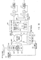
- FIG. 1 generally illustrates a data reproduction apparatus according to this invention wherein a data storage media (DSM) 1 comprises an optical disk that can be removed from a drive unit 2 that stores digital data such as video, audio, superimposed dialogue, and table of contents (TOC) information.
- DSM data storage media
- the DSM 1 may be a removable or detachable optical storage medium, magnetic storage medium, optoelectro medium or semiconductor storage element, or other digital data storage medium.
- the drive unit 2 has a mechanism section for mechanically loading and unloading the DSM 1 and a drive driving a pickup comprising an optical head for reading reproduction signals from the DSM 1.
- the pickup corresponds to the DSM 1, and may be a magnetic or an optoelectro head.
- the pickup also acts as an address pointer if the DSM 1 is a semiconductor element.
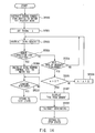
- the drive unit 2 has a demodulator that demodulates read-out reproduction signals to obtain subcode data, multiplexed data, error correction data (C1), and error correction data (C2), and sends it to the error correction device 3 in the format shown in FIG. 2.
- the error correction device 3 receives subcode data, multiplexed data, error correction data (C1), and error correction data (C2) sent from the drive unit 2 in the format shown in FIG. 2, and uses the error correction data to detect and correct errors. It also analyzes subcode data with an error corrected to obtain sector number data. It also appends sector number data and an error flag obtained from subcode data to multiplexed data with an error corrected, and transfers the multiplexed data to a ring buffer 4 in the format shown in FIG. 7A.
- FIG. 12 shows the configuration of an error correction device 3.
- a RAM 30 stores data supplied by the drive unit 2.
- a switch 31 switches to an error correction circuit 32 or a data addition circuit 34, the destination of data read from the RAM.
- the error correction circuit 32 uses error correction data (C1) and error correction data (C2) to correct errors.
- the data addition circuit adds sector number data and an error flag supplied by a controller 33 to multiplexed data read from the RAM 30.
- the controller 33 controls the addresses of the RAM and the switch 31, and analyzes subcode data. In the TOC readout state described below, the switch 31 can be continuously set to the error correction circuit 32 to carry out error correction for the same data a plurality of times.
- an error flag of "0" is added to the multiplexed data if the data involves no error or the error in the data is corrected completely, whereas an error flag of "1" is added to the data if the error is uncorrectable.
- the error correction device 3 sends subcode data to a subcode decoder 21 only if the data involves no error or if the error is corrected completely.
- the subcode decoder 21 decodes subcode data delivered from the error correction device 3 to pass the decoded data to a control circuit 16.
- the ring buffer 4 has a FIFO memory inside, and temporarily buffers multiplexed data, sector number data, and an error flag sent from the error correction device 3 in the format shown in FIG. 7A to transfer multiplexed data and the associated sector number data and error flag in the format shown in FIG. 7A in response to a read-out pointer indicated by a ring buffer control circuit 26.
- All data sent from the error correction device 3 may be buffered unconditionally; only a limited number of data may be selected and buffered starting with the sector number of a read start point specified by the controller 16; only a limited amount of data may be buffered ending with an end point specified by the controller; or only a limited amount of data may be buffered within the specific range between the sector number of a start point specified by the controller 16 and the sector number of an end point also specified by the controller 16. This can be switched via a ring buffer control circuit 26.
- the ring buffer control circuit 26 informs the controller 16 when the data at a buffer start or end point is detected. It also receives a TOC data load instruction to load TOC data sent from the error correction device 3 into a specific region for TOC data in a buffer memory, and detects the end of loading to communicate it to the controller 16. The ring buffer control circuit 26 transfers TOC data loaded and stored in the ring buffer 4 in response to a request from the controller 16. In addition, as with the ring buffer control circuit 106 and the track jump determination circuit 118 shown in FIG. 35, the ring buffer control circuit 26 monitors the amount of data stored in the ring buffer 4, and orders the drive section of the drive unit 2 to perform track jump as required.
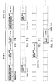
- the demultiplexer 5 divides multiplexed data sent from the ring buffer 4 and shown in FIG. 7A into a video bit stream, an audio bit stream, and a superimposed dialogue bit stream, and transfers video heads and data, audio heads and data, and superimposed dialogue heads and data to the video code buffer 6, the audio code buffer 9, and the superimposed dialogue code buffer 12, as shown in FIGS. 7B, 7C, and 7D respectively.
- the demultiplexer 5 sends an error flag corresponding to each of the video, the audio, or the superimposed dialogue data to the video code buffer 6, the audio code buffer 9, or the superimposed dialogue code buffer 12, respectively. However, it stops code requests to the ring buffer 26 and aborts data delivery to the video code buffer 6, the audio code buffer 9, and the superimposed dialogue code buffer 12 if it receives a signal meaning that the video code buffer 6, the audio code buffer 9, or the superimposed dialogue buffer 12 has overflowed.
- the demultiplexer 5 also detects sector number data, system clock references (SCR) stored in a system head, a video decoding time stamp (DTSV) stored in a video data head to show video data decoding start time, an audio decoding time stamp (DTSA) stored in an audio data head to show audio data decoding start time, and a superimposed dialogue decoding time stamp (DTSS) stored in a superimposed dialogue data head to show superimposed dialogue data decoding start time to send a signal to the controller 16 meaning that it has detected sector number data, an SCR, a DTSV, a DTSA, and a DTSS. It also retains detected sector number data, SCR, DTSV, DTSA, and DTSS, and communicates their contents to the controller 16 when ordered by the controller 16.
- SCR system clock references
- DTSV video decoding time stamp
- DTSA audio decoding time stamp
- DTSS superimposed dialogue decoding time stamp
- the demultiplexer 5 checks the continuity of sector numbers to find that data with discontinuous sector numbers has been delivered by the ring buffer 4, it inserts between the discontinuous sector dummy data containing an error flag of one or more byte, and passes the data to all of the video code buffer 6, the audio code buffer 9, and the superimposed dialogue code buffer 12 to inform them of the loss of data in that position or the presence of a discontinuous sector boundary created by search operation.
- the video code buffer 6 has a FIFO memory inside, and buffers video data heads and video data sent by the demultiplexer 5 to transfer them to a DTSV detector 7 when requested by the video decoder 8. It also issues a signal informing the demultiplexer 5 and the controller 16 of the overflow or the underflow of the video code buffer if the buffer memory overflows or underflows.
- the DTSV detector 7 enables only the video data of the video data head and video data sent from the video code buffer 6 to pass in order to transfer them to the video decoder 8. It also detects a DTSV in a video data head to issue a signal to the controller 16 meaning that the DTSV has been detected, and retains the detected DTSV in its internal register to inform the controller 16 of the retention when ordered by the controller 16.
- the video decoder 8 includes an MPEG decoder in conformity with ISO1172 (MPEG1) or ISO13818 (MPEG2), and decodes video data transferred from the DTSV detector 7 to send the results to a postprocessor 15. During decoding, it halts decoding, resumes decoding, searches for an I-picture head, and communicates the detection of an I-picture head to the controller 16.
- the MPEG decoder can detect a picture head, determine the type of picture head, that is, whether the picture head is an I-, a P-, or a B-picture head, and communicate the detection of the picture head and its type to the controller 16.
- the video decoder 8 temporarily replaces video data resulting from decoding with a black or blue screen to suppress output. It also sends a signal informing the controller 16 that an error is occurring if it finds that received compressed data contain syntactically inconsistent description or if it attempts to decode data with an error flag.
- the audio code buffer 9 has a FIFO memory inside, and buffers audio data heads and audio data sent by the demultiplexer 5 to transfer them to a DTSA detector 10 when requested by the audio decoder 11. It also issues a signal informing the demultiplexer 5 and the controller 16 of the overflow or the underflow of the audio code buffer if the buffer memory overflows or underflows.
- the DTSA detector 10 enables only the audio data of the audio data head and audio data sent from the audio code buffer 9 to pass in order to transfer them to the audio decoder 11. It also detects a DTSA in an audio data head to issue a signal to the controller 16 and the audio decoder 11, meaning that the DTSA has been detected. It also retains the detected DTSA in its internal register to inform the controller 16 of retention when ordered by the controller 16.
- the audio decoder 11 decodes compressed or noncompressed audio data transferred from the DTSA detector 10 to output the results to the audio output terminal. During decoding, it halts decoding, resumes decoding, repeats decoding of audio data for a specified duration, skips audio data for a specified duration.
- the specified duration refers to four levels of duration: 1 s, 100 ms, 10 ms, and 1 ms, and the minimum decoding unit for compressed data.
- the audio decoder 11 halts decoding when receiving a signal from the DTSA detector 10 meaning that a DTSA has been detected. It also has a half mute function for temporarily reducing the sound volume of decoded audio outputs by a specified level and a mute function for eliminating the sound volume.
- the superimposed dialogue code buffer 12 has a FIFO memory inside, and buffers superimposed dialogue data heads and superimposed dialogue data sent from the demultiplexer 5 to transfer them to a DTSS detector 13. It also issues a signal informing the demultiplexer 5 and the controller 16 of the overflow or the underflow of the superimposed dialogue code buffer if the buffer memory overflows or underflows.
- the DTSS detector 13 enables the passage of only the superimposed dialogue data of the superimposed dialogue data head and superimposed dialogue data sent from the superimposed dialogue code buffer 12 to transfer them to the superimposed dialogue decoder 14. It also detects a DTSS in superimposed dialogue data head and duration_time in superimposed dialogue data to issue a signal to the controller 16 meaning that they have been detected, and retains the detected DTSS and duration_time in its internal register to inform the controller 16 of the retention when ordered by the controller 16.
- the DTSS detector When a DTSS is detected during DTSS search operation, the DTSS detector issues a signal to the superimposed dialogue decoder 14 as well as the controller 16 meaning that the DTSS has been detected.
- the superimposed dialogue decoder 14 decodes superimposed dialogue data sent by the DTSS detector 13 to send the results to the postprocessor 15.
- the superimposed dialogue decoder 14 halts decoding, resumes decoding, and halts the output of the results of decoding.
- the superimposed dialogue decoder 14 skips superimposed dialogue data instead of decoding it until it receives a DTSS detection signal from the DTSS detector 13.
- the postprocessor 15 generates a video signal for displaying information showing the current state of the data reproduction apparatus in response to an instruction from the controller 16, and synthesizes a video signal sent from the video decoder 8, a video signal sent from the superimposed dialogue decoder 14, and a video signal issued to show the current state of the reproduction apparatus to output the synthesized video signal to the video output terminal.
- the controller 16 can receive information from each section and issue signals, and also can control the operation of the entire data reproduction apparatus shown in FIG. 1.
- An external interface 17 receives commands from computer equipment or editors to transmit them to the controller 16.
- a user input device 18 receives key inputs by users via pushbuttons or a remote commander to transmit them to the controller 16.
- An information display device 19 displays information showing the current state of the reproduction apparatus in response to an instruction from the controller 16 using, for example, lamps or a liquid crystal display.
- a vertical synchronizing signal generation circuit 22 generates vertical synchronizing signals to supply them to the video decoder 8, the superimposed dialogue data decoder 14, the postprocessor 15, and the controller 16.
- An STC register 23 is incremented in response to a signal from an STC countup circuit 24, and implements a reference clock for synchronously reproducing video, audio, and superimposed dialogue data.
- the controller 16 can set arbitrary values for the STC register 23.
- the STC register 23 in this embodiment is independent of the controller 16, while in another embodiment, it may be retained in the controller 16 as software.
- the STC countup circuit 24 generates signals such as pulse signals of a specified frequency to output them to the STC register 23. It also halts the output to the STC register 23 in response to an instruction from the controller 16.
- the STC countup circuit 24 and the STC register act as an internal clock STC.
- the STC countup register 24 in this embodiment is independent of the controller 16, while in another embodiment, it may be implemented as a count signal generator as software.
- the start position to read data from the DSM 1 is specified by the controller 16 using a sector number. Once a start position is specified, subsequent sectors are continuously read unless the controller 16 specifies a new position. For example, when sector 100 is specified as a start point, sectors are read out in the order of 100, 101, 102, 103, .... until a new readout position is specified.
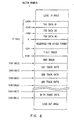
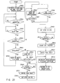
- FIG. 2 shows that each sector consists of 6,208 bytes and comprises four types of data: subcode data, multiplexed data, error correction data (C1) and error correction data (C2).
- the amount of these data in each sector is 64, 4096, 1024, and 1024 bytes, respectively.
- multiplexed data is reproduced, and the remaining three types of data, that is, subcode data, error correction data (C1), and error correction data (C2) are supplementary data for increasing the speed of multiplexing and the accuracy of reproduction.
- subcode data comprise sector number information, time code information, a subcode contents ID, and a reproduction inhibition flag.
- the sector number information contains the sector number of a sector
- the time code information contains information representing the time that the sector will be reproduced
- data contents contains information showing the contents of subcode data (for example, "01" if the data contains a reproduction inhibition flag)
- the reproduction inhibition flag contains a flag (for example, "FF") showing whether or not the sector is a lead-in area, a lead-out area, or an area where data such as TOC data that is not reproduced is stored.
- the remaining 59 bytes are reserved, and other information can be written to these bytes as subcode data.
- the multiplexed data includes multiplexed data comprising video, audio, and superimposed dialogue data to be reproduced and other data such as computer programs.
- C1 and C2 error correction data is correction information for detecting and correcting errors in subcode data and multiplexed data as well as the error correction data itself. Since C1 error correction data and C2 error correction data have different interleaving directions, repetition of corrections with both C1 and C2 improves the error correction ability.
- FIG. 3 shows the type of data stored in the multiplexed data section of each sector wherein the data are classified using sector numbers.
- the data stored in the multiplexed data essentially has video, audio, and superimposed dialogue data multiplexed therein, but exceptionally contain special data such as TOC data stored in sectors -3,000 to 1,023.
- Video, audio, and superimposed dialogue data to be reproduced is stored in sector 1,024 and subsequent sectors.
- An area called a TOC area is provided in sectors -3,000 to -1 of the DSM 1.
- the TOC area contains TOC data, that is, information for the contents of the stored in the DSM 1.
- the same TOC data are stored in three regions, that is, sectors -3,000 to -2,001, sectors -2,000 to -1,001, and sectors -1,000 to -1 to improve reliability for errors.
- the size of the TOC data must not exceed 1,000 sectors. Users can specify sector numbers via the user input device 18 or the ten keys in the external interface 17 to obtain desired images and voices.
- the TOC area is set with negative sector numbers that cannot be specified by ordinary ten-keypad keys.
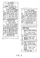
- FIG. 5 shows the configuration of TOC data.
- TOC data comprises a TOC header, a TOC size, number of tracks-information for each track, an entry point table header, an entry point table, and a TOC end mark.
- the TOC header contains a special data pattern showing that TOC starts in this position.
- the TOC size contains the length of TOC data in bytes.
- the information for each track comprises the track number of each track, a start sector number, an end sector number, a title track flag, an end track flag, a reproduction inhibition track flag, a video encoder flag, audio encoder flag, a superimposed dialogue encoder flag, and an encode flag valid information flag.
- the track number contains the serial number of a track.
- the normal range of the track number values must be 1 to 254.
- the start sector numnumber at the start point and the end sector number at the end point show the range of the track on the DSM 1.
- the title and the end track flags show that the track is a title or an end track, respectively.
- the reproduction inhibition flag is set to inhibit the reproduction of the track, and not set when the reproduction of the track is not inhibited.
- the video, audio, and superimposed dialogue multiplexing flag show whether or not video, audio, and superimposed dialogue data is multiplexed in the multiplexed data in the track, respectively.
- Each multiplexing flag may show the degree of multiplexing for each data type within the track.
- the multiplexing flag valid information flag shows whether or not the contents of the preceding video, audio, and superimposed dialogue multiplexing flags are valid. For example, each of the preceding three flags cannot be fixed to a single value if the state of multiplexing for video, audio, or superimposed dialogue data varies within a single track. In this case, an arbitrary value is written to the three flags, and a value showing invalidity is stored in the multiplexing flag valid information flag.
- an attribute indicating that the track is a title or an end track can be added to any of the tracks 1 to 254.
- the processing of the reproduction apparatus can be simplified by reducing the size of TOC data and ensuring that the DSM 1 contains only a single title track and a single end track by replacing the structure of the DSM in FIG. 3 with the structure shown in FIG. 4 and the structure of the TOC in FIG. 5 with the structure in FIG. 6 and providing special tracks with track numbers of 0 and 255 for a title and an end tracks and fixing their positions in the DSM 1.
- the entry point table header contains a special data pattern indicating that the entry point table starts in this position.
- the entry point table comprises the number of entry points and information for the entry points.
- the number of entry points comprises the number of entry points in the DSM 1, the positions of the entry points represented by sector numbers, and time code information stored in the subcode data in the sector.
- the entry point table is used during random access and search.
- the entry point table must be referenced when the video data are compressed at a variable rate in conformity with ISO11172 (MPEG1) or ISO13818 (MPEG2), because the increase in sector numbers is not proportional to the increase in time codes.
- the TOC end mark contains a special data pattern indicating that TOC ends in this position.
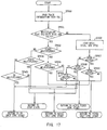
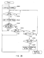
- FIG. 11 is a transition diagram of the operational state of the controller 16.
- the controller 16 enters the initialization state when the power source of the data reproduction apparatus shown in FIG. 1 is turned on.
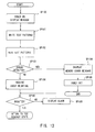
- FIG. 13 shows the flow of processing by the controller in its initialization state. In this state, the controller 16 instructs the information display device 19 to light a lamp indicating that the power source is turned on, and also instructs the postprocessor 15 to cause a display device such as CRT (not shown) to display a message showing that the power source is turned on (step SP100).
- a display device such as CRT (not shown)
- the controller subsequently reads the test patterns stored in the ROM 25 to write them into the corresponding memories installed in the error correction device 3, the ring buffer 4, the video code buffer 6, the audio code buffer 9, the superimposed dialogue code buffer 12, and the storage device 20, and then reads them from the memories (step SP102) to check whether or not these memories are operating accurately (memory check; step SP103).
- the controller instructs the information display device 19 to light a lamp indicating that an error is occurring, and also instructs the postprocessor 15 to cause a display device such as CRT (not shown) to display a message showing that an error is occurring in a memory (step SP104).
- the controller 16 subsequently ignores all input from the external interface 17 and the user input device 18 except a disk unload instruction. In addition, it reads no data or signal from the DSM 1.
- the controller 16 also turns off the power source for a specified period of time if an error is occurring in a memory (step SP105).
- the controller 16 sends a signal to the drive unit 2 inquiring whether or not the DSM 1 is loaded (step SP106).
- the drive unit 2 issues a signal to the controller 16 indicating whether or not DSM 1 is currently loaded. Whether or not the DSM 1 is loaded is determined by using for detection a microswitch installed in the mechanism section of the drive unit 2 or checking whether or not a focus can be applied in a predetermined part of the DSM 1. If the controller 16 receives a signal indicating that the DSM 1 is currently loaded, it enters the TOC readout state at step SP2 shown in FIG. 11 (step SP107).
- the controller 16 Conversely, if the controller 16 receives a signal indicating that the DSM 1 is not currently loaded, it instructs the information display device 19 to light a lamp indicating that the DSM 1 is not loaded, and also instructs the postprocessor 15 to display a message showing that the DSM 1 is not loaded (step SP108). The controller 16 subsequently waits until it receives a signal from the drive unit 2 indicating that the DSM 1 is loaded.
- the drive unit 2 detects the user's setting the DSM 1 into the drive unit 2 to perform mechanical loading such as the alignment of the DSM 1 in order to enable the pickup of the drive unit to read signals. Once loading is completed, the drive unit 2 sends a signal to the controller 16 indicating that the DSM 1 is loaded. The controller 16 enters the TOC readout state at step SP2 in FIG. 11 when receiving a signal indicating that loading is completed while waiting for a signal from the drive unit 2 indicating that the DSM 1 is loaded.
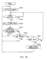
- FIG. 14 shows the flow of processing by the controller 16 in its TOC readout state.
- the controller 16 instructs the error correction device 3 to enter TOC readout mode (step SP200).
- the controller 16 also instructs the drive unit 2 to seek a section where the first TOC data is written, that is, sector -3,000 (steps SP201, SP202).
- the drive unit 2 reads out data from the DSM 1 to transfer it to the error correction device 3.
- the error correction device 3 detects and corrects any error in the data sent from the drive unit 2, and passes the multiplexed data to the ring buffer 4 and the subcode data to the subcode decoder 21.
- the number of possible repetitions of C1 and C2 corrections must be set larger than in normal reproduction because the controller 16 has instructed the drive unit to enter the TOC readout mode.
- both C1 and C2 error corrections executed by the error correction device 3 are carried out only once during normal data reproduction to reduce the time from the loading of data from the DSM 1 until video output from the postprocessor 15 or the audio decoder 11 and outputs from the audio output terminal.
- the error correction capability can be improved by repeating C1 and C2 error corrections a large number of times if the time from data loading until reproduction need not be reduced. Consequently, for the readout of TOC data which need not be fast but requires the high reliability of data, the error correction device 3 repeats error correction processing if the controller 16 has failed to correct an error despite its first attempt using a single C1 correction and a single C2 correction.
- the error correction device 3 may unconditionally repeat both C1 and C2 corrections several times, for example, four times.
- the controller 16 instructs the drive unit 2 to seek the position where the error is occurring, and reads data again from the DSM 1 to attempt to detect and correct the error in the loaded data. This rereadout processing is not performed during normal reproduction because it takes a large amount of time. In this TOC readout state, however, the controller 16 performs this operation.
- the controller 16 instructs the drive unit to seek the second of the TOC information stored in three different positions in the DSM 1 to load them, and then attempts to load the information into the ring buffer 4 as in the loading of the first TOC data.
- the controller 16 executes the same operation for the third TOC information if it has failed to read the second TOC information.
- Such readouts from different positions are possible because the same TOC data is stored in three positions, and impossible during normal reproduction. In this TOC readout state, however, the controller 16 carries out this operation (steps SP202, SP203, SP204, SP205, SP206).
- controller 16 If the controller 16 fails to read all TOC data stored in the three positions, it instructs the information display device 19 to light a lamp indicating that TOC readout has failed, and also instructs the postprocessor 15 to display a message on the screen showing a TOC readout error (step SP207). The controller 16 also instructs the drive unit 2 to unload the disk (step SP208), and enters the initialization state. The drive unit 2 unload the disk when receiving an unload instruction from the controller 16.
- the controller 16 instructs the ring buffer control circuit 26 to start TOC loading when TOC error correction is completed (step SP209).
- the ring buffer control circuit controls a write pointer to load the TOC data into a specific region for TOC data loading in the memory installed in the ring buffer 4.
- the ring buffer 4 writes into the region for TOC data in its memory, reproduction data transferred from the error correction device 3. In this case, all TOC data shown in FIG. 5 is loaded into the memory if the ring buffer 4 has a memory sufficient to store this amount, while, otherwise, the TOC data excluding the entry point table header and the entry point table are loaded.
- the ring buffer 4 can detect the loading of a TOC end mark to detect the end of loading of TOC data; when detecting the end of loading, the ring buffer 4 informs the controller 16 of this condition.
- the controller 16 receives a signal from the ring buffer 4 indicating the end of loading, and then enters the stop state (step SP210).
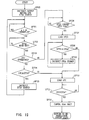
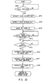
- FIG. 15 shows the flow of processing by the controller 16 in its stop state.
- the controller 16 determines whether or not the TOC has just been loaded (step SP300).
- the controller 16 reproduces the title track if TOC has just been loaded. Otherwise, for example, if the reproduction of all or part of the data from the DSM 1 has just been finished, the controller instructs reproduction of the end track.
- the controller 16 For the reproduction of a title track, the controller 16 references TOC data (step SP301), and if there is a track with a flag indicating that it is a title track, reproduces that track regardless of a reproduction instruction from the user (step SP302).
- the controller 16 For the reproduction of an end track, as in the reproduction of a title track, the controller 16 references TOC data (step SP303), and if there is a track with a flag indicating that it is an end track, reproduces that track regardless of a reproduction instruction from the user (step SP304).
- the controller 16 sends a stop instruction, an error correction halt instruction, a buffering halt instruction, and a demultiplexer stop instruction to the drive unit 2, the error correction device 3, the ring buffer 4, and the demultiplexer 5, respectively, if it cannot find a title or an end track to be reproduced or if the reproduction of a title or an end track is finished (step SP305). It also clears the video code buffer 6, the audio code buffer 9, and the superimposed dialogue code buffer 12 (step SP306).
- the controller 16 waits for an instruction to start reproduction sent by the user via the user input device 18 or the external interface 17 (step SP307). It also instructs the information display device 19 and the postprocessor 15 to light a lamp indicating the stop state and to display the associated message on the screen (step SP308).
- the user input device 18 sends a reproduction start signal to the controller 16 when the user carries out key inputs required to start reproduction. In this case, if the tracks to be reproduced have been specified by the user, the information for the track numbers is also transferred to the controller 16.
- the external interface 17 issues a reproduction start signal to the controller 16 when receiving the corresponding instruction from external equipment (not shown). In this case, or if the external equipment has specified the numbers of tracks to be reproduced, the track numbers are transferred to the controller 16.
- the controller 16 enters the reproduction ready state at step SP4 in FIG. 11 when receiving a reproduction start signal from the user input device 18 or the external interface circuit 17.
- the controller 16 starts reproduction with the track represented by track number "1" if the user input device 18 or the external interface circuit 17 has not specified the numbers of tracks to be reproduced.
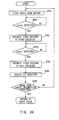
- FIG. 16 shows the flow of processing by the controller 16 in its reproduction ready state.
- the controller 16 instructs the information display device 19 and the postprocessor 15 to light a lamp indicating that reproduction is being prepared and to display the associated message on the screen (step SP400).
- the controller 16 then initializes the ring buffer 4, the demultiplexer 5, the video code buffer 6, the video decoder 8, the audio code buffer 9, the audio decoder 11, the superimposed dialogue code buffer 12, superimposed dialogue decoder 14, the postprocessor 15, and the storage device 20 (step SP401). However, it does not initialize the TOC data loaded and stored in the ring buffer 4.
- the controller 16 instructs the error correction device 3 to enter the normal reproduction mode (step SP402). This instruction causes the error correction device 3 to perform both C1 and C2 error corrections once when an error occurs.
- the controller 16 then references TOC data to obtain the sector number at the beginning of the tracks to be reproduced, and issues a seek instruction to the drive unit 2 using the sector number (step SP403).
- the controller 16 sends a demultiplexing start instruction to the demultiplexer 5 (step SP404).
- the demultiplexer 5 demultiplexes multiplexed bit streams passed from the ring buffer in the format shown in FIG. 7A, and then transfers them to the video code buffer 6, the audio code buffer 9, and the superimposed dialogue code buffer 12, as shown in FIGS. 7B, 7C, and 7D, respectively. It also detects the SCR stored in the system head, and retains it in its internal register.
- the video code buffer 6 stores data transferred from the demultiplexer 5 in its buffer memory, and then passes them to the DTSV detector 7.
- the audio code buffer 9 and the superimposed dialogue code buffer 12 stores data transferred from the demultiplexer 5 in their respective buffer memories, and then passes them to the DTSA detector 10 and the DTSS detector 13.
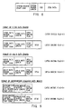
- the DTSV detector 7 selects only the video data of the data sent from the video code buffer 6 to transfer them to the video decoder 8. It also attempts to detect a DTSV in video header shown in FIG. 9, and when detecting a DTSV, communicates the detection to the controller 16 and retains the value of the DTSV. Similarly, the DTSA detector 10 and the DTSS detector 13 select only the audio and superimposed dialogue data of the data sent from the audio code buffer 9 and the superimposed dialogue buffer 12 to transfer them to the audio decoder 11 and the superimposed dialogue decoder 13, respectively. They also attempt to detect a DTSA in audio header shown in FIG. 9 and a DTSS in superimposed dialogue data header also shown in FIG. 9, and when detecting a DTSA and a DTSS, communicate the detection to the controller 16 and retains their values, respectively. After this processing is finished, the controller 16 enters the synchronized start method determination state at step SP5 in FIG. 11.
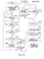
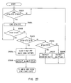
- FIG. 17 shows the flow of processing by the controller 16 in the synchronized start method determination state.
- the controller 16 executes processing required to start the reproduction of video, audio, and/or superimposed dialogue data. It selects a processing procedure used at the beginning of data reproduction using data contained in TOC and the detection state of a DTSV, a DTSA, or a DTSS to detect the presence of video, audio, and superimposed dialogue data in the data to be reproduced.
- the controller 16 references the video, the audio, and the superimposed dialogue multiplexing flags in the information for each track in the TOC data shown in FIG. 5 to detect the presence of video, audio, and superimposed dialogue data in the data to be reproduced.
- the controller 16 first loads from the TOC stored in the ring buffer 4, the track information corresponding to the tracks to be reproduced (step SP500). It then determines whether or not each of the multiplexing flags is valid based on the multiplexing flag valid information flag in the track information obtained (step SP501).
- the multiplexing flag valid information flag carries a value indicating invalidity, it executes the same determination based on the presence of a signal informing the detection of a DTSV, a DTSA, or a DTSS sent from the DTSV detector 7, the DTSA detector 10, or the DTSS detector 13 within a specified duration since the initiation of demultiplexing.
- the controller 16 enters the audio and video synchronized start state if it determines from the multiplexing flags in the TOC information that both video and audio data are present in the tracks to be reproduced or if both a DTSV and a DTSA are detected within a specified duration. It enters video-only synchronized start state if it determines from the multiplexing flags in the TOC information that video data are present in the tracks to be reproduced whereas audio data is not present in these tracks or if a DTSV has been detected within a specified duration whereas a DTSA has not been detected within the same duration.
- the controller 16 determines from the multiplexing flags in the TOC information that neither video nor audio data is present in the tracks to be reproduced or if neither a DTSV nor a DTSA is detected within a specified duration, it enters the superimposed dialogue synchronized start state if a DTSS has been detected by that point of time. Furthermore, the controller 16 enters the stop state if it determines from the TOC information that neither video nor audio nor superimposed dialogue data is present or if neither a DTSV nor a DTSA nor a DTSS has been detected within a specified duration (steps SP502 to SP510).
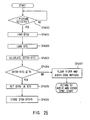
- FIG. 18 shows the flow of processing for video data executed by the controller 16 in its audio video synchronized start state.
- the controller 16 orders the video decoder 8 to halt decoding and to search for an I-picture header (step SP600). Since this causes an I-picture header to be searched for while decoding is halted, the video decoder 8 does not start decoding after detecting an I-picture header, and waits for a halt release instruction from the controller 16.
- the I-picture header is a particular data pattern placed at the beginning of intrapicture data in video data such as video bit streams defined by ISO11172 (MPEG1) or ISO13818 (MPEG2).
- Synchronization is started with I-pictures because the pictures, other than I-pictures, that is, P- and B-pictures are predictively encoded using pictures temporally located before and/or after these P- and the B-pictures and starting decoding with P- and B-pictures is thus impossible.
- the controller 16 determines whether or not the video code buffer 6 is underflowing (step SP601). If the video code buffer 6 is underflowing, the buffer has no data to be read out, so the controller 16 halts the reading of video data from the video code buffer 6. Next, when receiving a signal from the video decoder 8 indicating that an I-picture header has been read, the controller 16 loads the value of the DTSV from DTSV detector 16 (step SP602). The controller 16 then determines whether or not the STC countup circuit 24 is operating (step SP603).
- the controller performs the following processing for the video decoder 8 if the automatic countup of the STC has been turned on:
- the controller 16 first compares the STC stored in the STC register 23 with the DTSV detected by the DTSV detector 7 (step SP604). If DTSV ⁇ STC, it determines that it has missed the time to start decoding, instructs the video decoder 8 to search again for an I-picture header (step SP605), and loads from the DTSV detector 7, the DTSV corresponding to the next I-picture header on the video bit stream (step SP602).
- Error processing must usually be carried out when an underflow signal is detected in the video code buffer 6 or the audio code buffer 9.
- the controller 16 executes no special error processing even when receiving an underflow error signal from the video code buffer 6 after ordering the video decoder 8 to search for an I-picture header and before an I-picture is detected; the audio code buffer 9 waits until data is supplied from the demultiplexer 5 to clear the underflow state.
- the controller 16 must wait until a sufficient amount of data is stored in the video code buffer 6.
- the apparatus according to this invention fills the code buffer in the following manner if the STC fails to automatically count up, in order to obtain the predetermined fullness of code buffer specified in ISO11172 (MPEG1) or ISO13818 (MPEG2).
- the video decoder 8 If the video decoder 8 detects an I-picture, it can receive data from the demultiplexer 5 and store them in the video code buffer 5 until the buffer 6 overflows because the video decoder 8 has already halted decoding. Every time data is stored, the demultiplexer 5 attempts to detect a new SCR.
- the controller 16 loads a new SCR every specified duration which SCR updated every time data is stored in the video code buffer 6 (step SP606). It then compares this SCR with a DTSV loaded from the DTSV detector 7 (step SP607). At this point, if DTSV ⁇ SCR, it determines that a sufficient amount of data is stored in the code buffer. If DTSV > SCR, it waits until the demultiplexer 5 detects a new SCR. It also determines that a sufficient amount of data is stored in the code buffer if it receives a signal meaning overflow from the video code buffer 6, the audio code buffer 9, or the superimposed dialogue code buffer 12 while waiting for a new SCR to be detected (step SP608).
- the STC which is a system clock, must be started in synchronization with a vertical synchronization signal if the automatic countup of the STC has been turned off.
- the DTSV is encoded in synchronization with a vertical synchronization signal
- the DTSA is encoded independently of a vertical synchronization signal.
- the STC is thus started in synchronization with a vertical synchronization signal using the DTSV as an initial value.
- the decoding of audio data is started using the DTSA.
- the controller performs the following processing for the video decoder if the STC automatic countup has been turned off.
- the controller 16 sets a DTSV read from the DTSV detector 7 into the STC register 23 (step SP609).
- the controller 16 compares the DTSA read from the DTSA detector 10 with the DTSV read from the DTSV detector 7 (step SP610). If DTSA ⁇ DTSV, this means that audio data is decoded earlier than video data; the STC cannot thus be started in synchronization with a vertical synchronization signal. The controller 16 thus repeats issuance of a DTSA search instruction to the audio decoder 11 until DTSA > DTSV is met. The control of the audio decoder 11 is described below in detail.
- the controller 16 waits for a vertical synchronization signal from the vertical synchronization signal generation circuit 22, and causes the STC countup circuit 24 to operate in synchronization with a vertical synchronization signal to turn on the automatic countup of the STC (step SP612).
- the controller 16 sends a halt release instruction to the video decoder 8 to start decoding of video data while causing the STC countup circuit 24 to operate (step SP613).
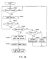
- FIG. 19 shows the flow of processing for audio data executed by the controller 16 in its audio and video synchronized start state.
- the controller 16 issues an output mute instruction and a DTSA search instruction to the audio decoder 11 (step SP700).
- the audio decoder 11 sends a code request to the audio code buffer 9, starts decoding, and waits for a signal from the DTSA detector 10 meaning that a DTSA signal has been detected. In this state, however, the audio decoder 11 does not actually output decode data due to the mute instruction that has been received.
- the controller 16 monitors the audio code buffer 9 for underflow (step SP701).
- the underflow of the audio code buffer 9 means that the audio code buffer 9 has no data to be delivered.
- the controller 16 causes the delivery of data from the audio code buffer 9 to be halted, and enables delivery again when underflow is resolved.
- the decoder 11 halts decoding when receiving a signal from the DTSA detector 10 meaning that a DTSA signal has been detected.
- the controller 16 can load the detected DTSA from the DTSA detector 10 (step SP702).
- the halt state of the audio decoder 11 can be released by the controller 16 as described below.
- the controller 16 determines the operational state of the STC (step SP703).
- the controller executes the same processing for the audio decoder 11 as for the video decoder 8 if the automatic countup of the STC has been turned on. That is, the controller 16 compares the most recent STC loaded from the STC register 23 with the most recent DTSA loaded from the DTSA detector 10 (step SP704), and repeats issuance of a DTSA search instruction to the audio decoder 11 until DTSA > STC is met (step SP705).
- the controller 16 performs the following processing for the audio decoder if the automatic countup of the STC has been turned off. That is, the controller determines that a DTSV has already been loaded during the synchronized start processing for the video decoder 8 in FIG. 18 (step SP706). If a DTSV has been loaded, the controller 16 loads it for synchronized start processing for the audio decoder 11 (step SP707). The controller 16 subsequently compares with the loaded DTSV with a DTSA (step SP708), and repeats issuance of a DTSA search instruction to the audio decoder 11 until DTSA > DTSV is met (step SP709).
- the controller 16 When DTSA > DTSV is met, the value of the STC can be loaded for synchronized start processing for the audio decoder 11 at this point because the STC countup circuit 24 has been operated to turn on the automatic countup of the STC during the synchronized start processing for the video decoder 8 in FIG. 18, as described above.
- FIG. 20 shows the flow of processing by the controller 16 in its video-only synchronized start state.
- the controller 16 executes processing required to start only video data in synchronization with a vertical synchronization signal.
- Processing by the controller 16 in the video-only synchronized start state is fundamentally the same as that in the audio video synchronized start state except for the absence of the comparison of the DTSV with the DTSA, that is, step SP610 in FIG. 18. Detailed description will therefore be omitted here.
- the controller 16 instructs the video decoder 8 to halt decoding and to search for an I-picture header (step SP800).
- the controller 16 If the video decode 18 detects an I-picture, that is, the controller 16 loads a DTSV (step SP 802) and the STC has been turned off, the controller 16 then waits for a sufficient amount of data to be stored in the video code buffer 6. That is, as in the audio video synchronized start, the controller 16 compares the detected DTSV with the most recent SCR read out from the demultiplexer 5, and waits until DTSV ⁇ SCR is met or it receives a signal indicating overflow from the video code buffer 6, the audio code buffer 9, or the superimposed dialogue code buffer 12 (step SP806, SP807, SP808).
- the controller 16 performs no processing if the audio decoder 11 has already started decoding and, otherwise, sends an output mute instruction and a DTSA search instruction to the audio decoder 11 to cause the decoder to wait for audio data to be transferred from the demultiplexer 5 to the audio code buffer 9.
- the controller 16 further executes the following processing. If the automatic countup of the STC has been turned on, it carries out the same processing as in the audio video synchronized start with the automatic countup of the STC turned on (step SP804, SP805, SP814, SP815, SP816, SP817, SP818). At this point, the controller 16 performs no processing for audio data.
- the controller 16 sends a decoding start instruction to the superimposed dialogue decoder, and enters the reproduction steady state.
- the controller 16 enters the audio-only synchronized start state at step 804 and subsequent steps shown in FIG. 21 if it receives a signal from the DTSA detector 10 indicating that a DTSA has been detected after starting reproduction in the video-only synchronized start state and then entering the reproduction steady state.
- FIG. 21 shows the flow of processing by the controller 16 in its audio-only synchronized start state.
- the controller 16 executes processing required to start only audio data in synchronization with the STC.
- the controller performs no processing if the video decoder 8 has already started decoding, and otherwise, sends an I-picture header search instruction to the video decoder 8.
- the controller 16 When entering the audio-only synchronized start state, the controller 16 sends an output mute instruction and a DTSA search instruction to the audio decoder 11 (step SP900).
- the audio decoder 11 delivers a code request to the audio code buffer 9, starts decoding, and waits for a signal from the DTSA detector 10 meaning that a DTSA signal has been detected. In this state, however, the audio decoder 11 does not actually output decoded data due to the mute instruction it has received.
- the controller 16 monitors the audio code buffer 9 for underflow (step SP901). The underflow of the audio code buffer 9 means that the audio code buffer 9 has no data to be delivered.
- the controller 16 when detecting this, the controller 16 causes the delivery of data from the audio code buffer 9 to be halted, and enables the delivery again when underflow is resolved.
- the audio decoder 11 halts decoding when receiving a signal from the DTSA detector 10 meaning that a DTSA signal has been detected.
- the controller 16 can load the detected DTSA from the DTSA detector 10 (step SP902).
- the halt state of the audio decoder 11 can be released by the controller 16 as described below.
- the controller 16 determines the operational state of the STC (step SP903).
- the controller executes the following processing if the automatic countup of the STC has been turned on: That is, the controller 16 compares the most recent STC loaded from the STC register 23 with the most recent DTSA loaded from the DTSA detector 10 (step SP904), and repeats issuance of a DTSA search instruction to the audio decoder 11 until DTSA > STC is met (step SP905).
- the controller 16 starts to wait until a sufficient amount of data is stored in the audio code buffer 9 when the DTSA detector 10 detects a DTSA. That is, as in the above process of waiting until a sufficient amount of data is stored in the video code buffer 6, the controller 16 reads the most recent SCR from the demultiplexer 5 (step SP906), compares this SCR with the readout DTSA (step SP907), and waits until DTSA ⁇ SCR is met or it receives a signal indicating overflow from the video code buffer 6, the audio code buffer 9, or the superimposed dialogue code buffer 12 (step SP908).
- the controller 16 then starts the automatic countup of the STC at the same time when the audio decoder starts decoding. That is, when detecting that a sufficient amount of data is stored in the audio code buffer 9, the controller 16 sets the value of DTSA detected by the DTSA detector into the STC register 23 (step SP909), and causes the STC countup circuit 24 to operate to turn on automatic countup of the STC (step SP910). While causing the STC countup circuit 24 to operate, the controller 16 issues a halt release instruction to the audio decoder 11 to start decoding audio data (step SP911).
- the controller 16 sends a decoding start instruction to the superimposed dialogue decoder (step SP912), and enters the reproduction steady state.
- the controller 16 enters the video-only synchronized start state at step 804 and subsequent steps shown in FIG. 20 if it receives a signal from the DTSV detector 7 indicating that a DTSV has been detected after starting reproduction in the audio-only synchronized start state and then entering the reproduction steady state.
- FIG. 22 shows the flow of processing by the controller 16 in its superimposed dialogue-only synchronized start state.
- the controller 16 executes processing required to start only superimposed dialogue data in synchronization with the STC.
- Superimposed dialogue data is among video data.
- video data 8 used by the video decoder of the present apparatus has a display duration on a single screen of about 1/25 to about 1/30 second
- superimposed dialogue data used by the present apparatus is image data wherein the same screen is displayed over a relatively long duration of about one second or more on a single screen as in superimposed dialogue synthesized or superimposed in movies or TV programs.
- superimposed dialogue data Since superimposed dialogue data has the above characteristic, an amount of superimposed dialogue data for a single screen must be stored in the DSM 1 at a lower transfer rate than video and audio data also stored on the DSM 1.
- the present apparatus that reproduces data stored in such a manner loads through the superimposed dialogue buffer 12 and the DTSS detector 13 superimposed dialogue data delivered at a low transfer rate, and after decoding them by the superimposed dialogue decoder 14, outputs them to the postprocessor 15.
- the controller performs no processing if the video decoder 8 has already started decoding and, otherwise, sends an I-picture header search instruction to the video decoder 8 to cause the decoder to wait for video data to be transferred from the demultiplexer 5 to the video code buffer 6.
- the controller performs no processing if the audio decoder 11 has already started decoding and, otherwise, sends an output mute instruction and a DTSA search instruction to the audio decoder 11 to cause the decoder to wait for audio data to be transferred from the demultiplexer 5 to the audio code buffer 9.
- the controller 16 For superimposed dialogue data, if the automatic countup of the STC has been turned on, the controller displays superimposed dialogue using the same processing procedure as in the reproduction steady state described below.
- the controller 16 first determines whether or not the countup of the STC has been turned on (step SP1000). If the automatic countup of the STC has been turned off, the controller, after executing the following processing, displays superimposed dialogue using the same processing procedure as in the reproduction steady state described below: If the automatic countup of the STC has been turned off, the controller 16 sends a DTSS search instruction to the superimposed dialogue decoder 14 (step SP1001), and waits for the DTSS detector 13 to detect a DTSS (step SP1002).
- the controller then loads a detected DTSS (step SP1003).
- the superimposed dialogue code buffer 12 may overflow because the STC has not been started, thereby preventing a decoding start instruction to be issued to the superimposed dialogue decoder 14. Consequently, when receiving a signal meaning overflow from the superimposed dialogue code buffer 12 (step SP1004), the controller 16 sets into the STC register 23 a DTSS read out from the DTSS detector 13 (step SP1005), waits for a vertical synchronization signal from the vertical synchronization signal generation circuit 22 (step SP1006), causes the STC countup circuit 24 to operate (step SP1007), and starts the superimposed dialogue decode (step SP1008). After the above processing is finished, the controller 16 enters the reproduction steady state.
- the controller 16 enters the video-only synchronized start state at step SP804 if it receives a signal from the DTSV detector 7 indicating that a DTSV has been detected after starting reproduction in the superimposed dialogue-only synchronized start state and then entering the reproduction steady state.
- the controller 16 enters the audio-only synchronized start state at step SP904 if it receives a signal from the DTSA detector 10 indicating that a DTSA has been detected after starting reproduction in the superimposed dialogue-only synchronized start state and then entering the reproduction steady state.
- the controller 16 enters the audio and video synchronized start state at steps SP604 and SP704 if it receives a signal from both the DTSV detector 7 and the DTSA detector 10 indicating that a DTSV and a DTSA have been detected after starting reproduction in the superimposed dialogue-only synchronized start state and then entering the reproduction steady state.
- the controller 16 When returning to the reproduction steady state, the controller 16 detects errors in video synchronization, detects and corrects errors in audio synchronization, detects other errors, controls the superimposed dialogue decoder, and checks the reproduction program.
- Possible errors in synchronization include the difference between the system clock STC and the video decoding start time DTSV and the difference between the system clock STC and the audio decoding start time DTSA.
- Two methods are available for the detection of synchronization errors. One method is to detect both differences to take corrective action such that both differences can be substantially eliminated. The other method is to treat one of the difference as a reference while detecting the other difference and taking action required to correct this difference.
- the former method is to adjust all the differences to a specified reference STC to correct errors in synchronization of video data with audio data.
- the latter method initializes the STC to the DTSV periodically or at a specified time interval to eliminate this difference in a mathematical sense.
- the difference between the system STC and the audio decoding start time DTSA is represented as its original value plus the value of the difference between the STC and the DTSV.
- Errors in the synchronization of video, audio, and superimposed dialogue data can thus be relatively corrected by eliminating only the difference associated with the DTSA.
- FIG. 23 shows the flow of processing executed by the controller 16 in the former video synchronization error detection method. That is, when receiving a signal from the video decoder 8 meaning that an I-picture header has been detected (step SP2000), the controller 16 loads the most recent DTSV from the DTSV detector 7 and an STC from the STC register 23 (steps SP2001, SP2002), and calculates the difference between the DTSV and STC, that is, (DTSV - STC) (step SP2003) to store the result in the storage device 20.
- FIG. 24 shows the flow of processing executed by the controller 16 in the former audio synchronization error detection method.
- the controller 16 loads the most recent DTSA from the DTSA detector 10 and an STC from the STC register 23 (steps SP3001, SP3002), and calculates the difference between the DTSA and STC, that is, (DTSA - STC) (step SP3003) to store the result in the storage device 20 (step SP3004).
- FIG. 25 shows the flow of processing executed by the controller 16 in the latter video synchronization error detection method.
- the controller 16 loads the most recent DTSV from the DTSV detector 7 and an STC from the STC register 23 (steps SP4001, SP4002), and calculates the absolute value of the difference between the DTSV and STC, that is,
- the controller then compares
- the controller determines that a serious synchronization error is occurring and that the DTSV cannot be used as a reference, and clears the video code buffer 6 and the audio code buffer 9 to enter the audio and video synchronized start state (step SP4007).
- the storage device 20 stores a value of "0" as (DTSV - STC) if
- FIG. 24 also shows the flow of processing by the controller 16 in the latter audio synchronization error detection method. That is, when receiving a signal from the DTSA detector 10 meaning that a DTSA has been detected, the controller 16 loads the most recent DTSA from the DTSA detector 10 and an STC from the STC register 23. It then calculates the difference between the DTSA and STC, that is, (DTSA - STC) to store the result in the storage device 20.
- Hardware such as an adder, a subtracter, and a comparator can also be used to cause the controller 16 to set the values of the STC, the DTSV, and the DTSA and to read out the results of calculation if the controller must spend a large amount of time calculating (DTSV - STC), (DTSA - STC), and
- FIG. 26 shows the flow of processing by the controller in correcting synchronization errors associated with the DTSV.
- step SP5004 determines that a serious synchronization error is occurring, and clears the video code buffer 6 and the audio code buffer 9 (step SP5004) to enter the audio and video synchronized start state. If the absolute value of (DTSV - STC) does not exceed the specified value, it determines whether the DTSV is positive or negative (step SP5,006). If (DTSV - STC) > 0, the decoding of video data has progressed relative to the STC. The controller 16 thus instructs the video decoder 8 to halt decoding for an appropriate number of pictures corresponding to the magnitude of
- FIG. 27 shows the flow of processing executed by the controller to correct synchronization errors associated with the DTSA.
- step SP6006 determines whether the DTSA is positive or negative. If (DTSA -STC) > 0, the decoding of audio data has advanced relative to the STC. The controller 16 thus instructs the audio decoder 11 to halt decoding for an appropriate number of pictures corresponding to the magnitude of
- the controller 16 may instruct the information display device 19 and the postprocessor 15 to light a lamp indicating that a substantial amount of video data may have been lost and to display this condition on the screen if it determines that a serious synchronization error is occurring (steps SP5006, SP6005).
- data read from the DSM 1 have errors corrected by the error correction device 3
- data containing a large amount of error data may be sent to the video decoder 8, the audio decoder 11, or the superimposed dialogue decoder 14 via the demultiplexer 5 without having the errors completely corrected.
- error flags contained in error data enable the video decoder 8, the audio decoder, 11, and the superimposed dialogue decoder 14 to detect the errors.
- both the video decoder 8 and the audio decoder 11 decode video or audio data in conformity with ISO11172 (MPEG1) or ISO13818 (MPEG2), they can detect errors by attempting to find data inconsistent with this syntax. In any case, when detecting an error, the video decoder 8, the audio decoder 11, and the superimposed dialogue decoder 14 send a signal to the controller 16 informing it of the presence of the error.
- a decoding error is detected in the video decoder 8 or the audio decoder 11, video or audio data may have been lost, and the synchronization of displayed images with output voices may thus fail if reproduction is continued.
- Such a synchronization error can be corrected by the above synchronization error detection and correction method.
- the controller 16 can count the frequency of errors to understand disk error generation conditions. This enables the error correction algorithm of the error correction device 3 to be modified or the error generation conditions to be notified to the user.
- the controller 16 calculates the frequency of errors occurring in the disk, or in the track, or within the past specified duration by counting the number of received signals informing the presence of an error.
- three error frequency storage regions are provided in the storage device 20: a disk error frequency storage region, an track error frequency storage region, and a three-second error frequency storage region, and these regions operate as counters.
- FIGS. 28, 29, and 30 show the flow of processing executed by the controller to detect errors using each of the counters.
- the disk error frequency storage region is reset when the stop state is shifted to the reproduction ready state, the track error frequency storage region is also reset when the stop state is shifted to the reproduction ready state and the new track reproduction, and the three-second error frequency storage region is also reset when the stop state is shifted to the reproduction ready state as well every three seconds (steps SP7000, SP7003, SP8000, SP8003, SP8004, SP9000, SP9003, SP9004).
- the controller 16 If the controller 16 receives an error signal from the video decoder 8, the audio decoder 11, or the superimposed dialogue decoder 14 (steps SP7001, SP8001, SP9001), it adds 1 to each of the values stored in the disk, the track, and the three-second error frequency storage regions (steps SP7002, SP8002, SP9002). After the addition, if the value in the disk error frequency storage region exceeds the predetermined threshold, the controller 16 determines that the DSM 1 being reproduced has a large number of defects (step SP7004) to enter the stop state.
- step SP8005 the controller 16 determines that this track has a large number of defects, and suspends the reproduction of the track to start the reproduction of the next track (steps SP8006, SP8007). However, it suspends reproduction to enter the stop state if it finds from the TOC data that the next data do not exist. If the value in the three-second error frequency storage region exceeds the predetermined threshold (step SP9005), the controller 16 instructs the video decoder 8 and the superimposed dialogue decoder 14 to halt the display of the screen and the audio decoder 11 to mute outputs for the next three seconds (step SP9006).
- the controller 16 loads sector number data from the demultiplexer 5 when receiving a signal from the demultiplexer 5 indicating that sector numbers have been detected.
- the controller compares the loaded sector number data with the start and the end sector numbers of each track in the TOC data shown in FIG. 5 to detect whether or not the sector numbers read from the demultiplexer 5 belong to that track. If the numbers do not belong to the track being currently reproduced, the controller 16 instructs the information display device 19 and the postprocessor 15 to light a lamp indicating the fact that the reproduced track has been changed and/or the number of the reproduced track and to display them on the screen.
- controller 16 instructs the demultiplexer 5 to stop demultiplexing if it detects that the reproduction of the final track is finished.
- the controller 16 subsequently waits for an underflow error signal indicating that all of the video code buffer 8, the audio code buffer 11, and the superimposed dialogue code buffer 12 have become empty, and then enters the stop state.
- the controller 16 loads subcode data from the subcode decoder 21 as when loading sector numbers from the demultiplexer 5. As in sector number data read from the demultiplexer 5, the controller 16 compares the loaded subcode data with the start and the end sector numbers of each track in the TOC data shown in FIG. 5 to identify the number of the track to which the data are currently being input to the error correction device 3. If the identified track differs from the track being currently reproduced and if the user has specified reproduction in an inconsecutive order, the controller enters the reproduction ready state to reproduce the next track to be reproduced in that order.
- the controller 16 enters the stop state if it receives a stop instruction from the user input device 18 or the external interface 17.
- the controller 16 enters the search state if it receives a search instruction from the user input device 18 or the external interface 17.
- the controller 16 enters the pause state if it receives a pause instruction from the user input device 18 or the external interface 17.
- Superimposed dialogue data are encoded in each screen.
- a DTSS indicating that decoding start time of each superimposed dialogue screen is stored in the superimposed dialogue data header contained in the leading data for the superimposed dialogue screen.
- a duration_time indicating the display duration of a superimposed dialogue screen is stored at the beginning of the superimposed dialogue screen in each superimposed dialogue data.
- the DTSS is stored in no superimposed dialogue data headers other than in the leading data for each superimposed dialogue screen.
- the leading data for a superimposed dialogue screen can be searched for by searching for the DTSS.
- FIG. 31 shows the flow of processing executed by the controller 16 to control the superimposed dialogue decoder in the reproduction steady state.
- the controller 16 checks the decoding start time when receiving a DTSS detection signal from the DTSS detector 25. It first reads the detected DTSS from the DTSS detector 25 and the current value of the STC from the STC register 23 (steps SP33, SP34). It then compares the readout DTSS with this STC (step SP35). If DTSS ⁇ STC, it determines that it has missed the decoding timing, and clears the superimposed dialogue buffer (step SP43). The controller then issues a DTSS search instruction to the DTSS detector 25 and the superimposed dialogue decoder 14 (step SP30). It then waits for a DTSS detection signal from the DTSS detector 25 (step SP31), and, if a DTSS is detected, checks the decoding start time for the next superimposed dialogue screen.
- DTSS STC
- the controller determines that decoding should be started and issues an instruction to decode data for a single screen.
- the superimposed dialogue decoder 14 decodes superimposed dialogue data for a single screen which are obtained from the superimposed dialogue code buffer 12 via the DTSS detector 25 and retains them in its internal frame memory. It then starts outputting the data to the postprocessor 15.
- the controller 16 waits until DTSS + duration_time > STC is met (steps SP40, SP41). During this operation, the superimposed dialogue screen continues to be displayed.
- the controller issues a display stop instruction to the superimposed dialogue decoder 14 (step SP42) to end the display of the superimposed dialogue screen.
- the DTSS corresponding to the leading data for the next superimposed dialogue screen may be detected while the controller 16 is waiting until DTSS + duration_time > STC. In this case, the controller carries out no processing until DTSS + duration_time > STC is met to cause the display of the superimposed dialogue screen to be finished.
- the controller reads out the DTSS for the next superimposed dialogue screen from the DTSS detector 25 to check the decoding start time if the DTSS corresponding to the leading data for the next superimposed dialogue screen is detected while the controller 16 is waiting for DTSS + duration_time > STC to be met.
- a threshold for example, duration_time
- the controller 16 determines that a serious synchronization error is occurring and issues a DTSS search instruction to the superimposed dialogue decoder 14 and the DTSS detector 25 (step SP30). When a DTSS is detected, it checks the decoding start time for this superimposed dialogue screen.
- the search state is an operation for reproducing only the I-pictures of video data which appear at a specified interval and skipping the P- and the B-pictures between the I-pictures instead of reproducing them to reproduce video data stored in the DSM 1 in a shorter time than in normal reproduction.
- Selective display of only I-pictures in the same direction as in normal reproduction is referred to as forward search, while selective display of I-pictures in the direction reverse to that of normal reproduction, that is, the direction in which the reproduction time becomes sequentially earlier.
- FIG. 32 shows the flow of processing by the controller 16 in its search state.
- the controller 16 sends a signal to the video coder 8 meaning that it has entered the search state (step SP50).
- the video decoder 8 decodes only the I-picture data of the data loaded from the DTSV detector 7 and skips the other data, that is, the P- and the B-picture data instead of decoding them.
- the decoded I-pictures are displayed immediately after decoding.
- the controller also instructs the audio decoder 11 to stop decoding and to mute output sounds, and also instructs the superimposed dialogue decoder 14 to stop decoding and to halt decoding outputs (steps SP51, SP52). This prevents audio and superimposed dialogue data from being reproduced during search.
- the controller 16 instructs the drive unit 2 to perform track jump in the forward direction of the pickup, whereas, for the reverse search, it instructs the drive unit 2 to execute reverse track jump (step SP53).
- the drive unit 2 causes the pickup to move in such a way that, for the forward track jump instruction, data can be read from a large sector number relative to the current position of the pickup whereas, for the reverse track jump instruction, data can be read from a small sector number relative to the same position.
- the amount of the movement of the pickup during track jump need not be specified accurately. That is, unlike a seek instruction wherein the number of the sector to which the pickup should move is rigidly specified, these instructions do not require the amount of jump to be specified accurately due to the combination of the DSM 1 and the drive unit 2 that can only designate an approximate movement direction and an approximate amount of movement when desired jump is fast and involves a very large amount of movement.
- subcode data in the format shown in FIG. 2 are loaded into the subcode decoder 21.
- the controller 16 loads sector number data and a reproduction inhibition flag from the subcode data loaded into the subcode decoder 21 (step SP54).
- step SP55 If the loaded reproduction inhibition flag is set (step SP55), that is, means that reproduction is inhibited, the controller 16 determines that, after track jump, the pickup has entered a lead in area, a lead out area, or a TOC area, and enters the stop state. Otherwise, the multiplexed data at the sector number read after track jump are supplied to the video decoder 8, the audio decoder 11, and the superimposed dialogue decoder 14.
- the video decoder 8 Since the video decoder 8 is in the search state, it searches for an I-picture header to reproduce only I-pictures. When detecting an I-picture header, the video decoder 8 sends a signal to the controller 16 informing that an I-picture header has been detected, and promptly decodes the I-picture to output it immediately after completing decoding. If it next detects a P- or a B-picture header, it informs the controller 16 of the detection, and starts searching for the next I-picture header instead of decoding the P- or the B-picture data.
- the controller 16 When entering the search state, the controller 16 starts to wait for a signal from the video decoder 8 informing an I-picture header has been detected (step SP56). When receiving an I-picture header detection signal, it starts to wait for a next P- or B-picture header detection signal (step SP58). When receiving a P- or B-picture header detection signal, the controller 16 determines that the decoding of the I-picture is finished. Again, for forward search, the controller 16 instructs the drive unit 2 to cause track jump of the pickup in the forward direction whereas for reverse search, it instructs the drive unit 2 to cause track jump of the pickup in the reverse direction in order to repeat the above search state (step SP53).
- audio and superimposed dialogue data are loaded into the audio code buffer 9 and the superimposed dialogue code buffer 12, respectively.
- the audio code buffer 9 and/or the superimposed dialogue code buffer 12 may overflow, thereby preventing the demultiplexer 5 from transferring data to the video code buffer 6, the audio code buffer 9, and the superimpozed dialogue code buffer 12.
- the controller 16 periodically clears the audio code buffer 9 and the superimposed dialogue code buffer 12. For example, it clears these buffers each time the controller receives an I-, a P-, or a B-picture header detection signal from the video decoder 8 (step SP57, SP58).
- the controller 16 enters the synchronized start method determination state if it receives a search operation release instruction from the user input device 18 or the external interface 17.
- the controller 16 enters the stop state if it receives a stop instruction from the user input device 18 or the external interface 17.
- FIG. 33 shows the flow of processing by the controller 16 in its pause state.
- the controller 16 starts to wait a vertical synchronization signal from the vertical synchronization generator (step SP70).
- a vertical synchronization signal When detecting a vertical synchronization signal, it issues a halt instruction to the video decoder 8 and a decoding stop instruction to the audio decoder 11, and simultaneously instructs the STC countup circuit to abort the automatic countup of the STC (step SP71, SP72, SP73).
- the video decoder 8 When receiving a halt instruction, the video decoder 8 halts decoding and continues to display the last decoded screen. In this case, if the image being decoded is an interlaced image wherein a single screen comprises two fields with a temporal difference, the video decoder 8 selects one of the odd and the even number fields constituting this image to display the selected field even when the other field should be displayed, thereby restraining flickering. When receiving a decoding stop instruction, the audio decoder 11 promptly aborts decoding.
- the controller 16 In the pause state, if a superimposed dialogue screen is displayed at the moment when the normal reproduction state is shifted to the pause state, this screen continues to be displayed. Otherwise, no superimposed dialogue screen is displayed.
- the controller 16 when receiving a pause release instruction from the user input device 18 or the external interface 17, the controller 16 starts to wait for a vertical synchronization signal from the vertical synchronization signal generator (steps SP74, SP75). When detecting a vertical synchronization signal, it issues a pause release instruction to the video decoder 8 and a decoding start instruction to the audio decoder 11, and simultaneously instructs the STC countup circuit to start the automatic countup of the STC (step SP76, SP77, SP78). The controller 16 subsequently enters the normal reproduction state.
- the controller 16 In the pause state, the controller 16 enters the frame feed state if it receives a frame feed instruction from the user input device 18 or the external interface 17.
- FIG. 34 show the flow of processing by the controller 16 in its frame feed state.
- the controller 16 When entering the frame feed state, the controller 16 first orders the audio code buffer 9 to be cleared (step SP90). This is to avoid the underflow of the audio code buffer during the next decoding of a single screen by the video decoder.
- the controller then forces the video decoder 8 to decode a single frame. That is, the controller waits for a vertical synchronization signal from the vertical synchronization generation circuit 22 (step SP91), sends a decoding start instruction to the video decoder 8 in response to a vertical synchronization signal (step SP92), and issues a halt instruction in response to the next vertical synchronization signal (steps SP93, SP94).
- the controller sets the STC forward by one frame (step SP95). That is, the controller 16 reads out an STC from the STC register 23 to add one frame of display time to this STC, and then sets the result back into the STC register 23.
- the controller 16 determines whether or not the user input device 18 or the external interface 17 is issuing a frame feed release instruction (step SP96), and if not, repeats the above processing.
- the controller performs the following processing for the superimposed dialogue screen as in the normal reproduction state: If a superimposed dialogue screen is currently displayed, it issues a display stop instruction to the superimposed dialogue decoder 14 when DTSS + duration_time > STC is met, thereby ending the display the superimposed dialogue screen. Otherwise, it instructs the superimposed dialogue decoder 14 to display the next superimposed dialogue screen when DTSS ⁇ STC is met. After finishing the above processing, the controller moves from the frame feed state to the pause state.
- this invention implements a data reproduction apparatus and a data storage medium for reproducing multiplexed data with video, audio, and superimposed dialogue data compressed at a variable rate and performing various functions.
- the data storage medium according to this invention is applicable to digital video disks (DVDS) wherein bit streams compressed using MPEG are stored.
- the data reproduction apparatus according to this invention is applicable to reproduction devices for reproducing such DVDs.
Abstract
Description
- The present invention relates to a data reproduction apparatus and a data storage medium that can be preferably applied to, for example, those using a storage medium with digitalized moving picture stored therein.
- A conventional data reproduction apparatus that reproduces data from a disk as a storage medium with digitalized moving picture stored therein is described as a variable-rate-sensitive data reproduction apparatus as shown in FIG. 35 in the applicant's Japanese Patent Laid Open No.6-124,168 (publicized on May 6, 1994). This reproduction apparatus reproduces data stored on an
optical disk 101 using apickup 102. Thepickup 102 irradiates theoptical disk 101 with laser beams and uses light reflected from theoptic disk 101 to reproduce the data stored therein. Signals reproduced by thepickup 102 are delivered to ademodulator 103. Thedemodulator 103 demodulates the reproduced signals output by theoptic pickup 102 to output them to asector detector 104. - The
sector detector 104 detects an address stored in each sector from the delivered data to output it to a ringbuffer control circuit 106. It also outputs the data to anECC circuit 105 located after the sector detector while maintaining sector synchronization. Thesector detector 104 outputs a sector number error signal to a trackjump determination circuit 118 via the ringbuffer control circuit 106 if the detector fails to detect addresses or if detected addresses are not continuous. - The
ECC circuit 105 detects an error in data supplied by thesector detector 104, and uses redundant bits contained in the data to correct the error to output the corrected data to a ring buffer memory (FIFO) 107 for the ring jump. Furthermore, if theECC circuit 105 fails to correct an error in data, it outputs an error generation signal to the trackjump determination circuit 118. - The ring
buffer control circuit 106 controls writes to and reads from thering buffer memory 107, and monitors a code request signal requesting data output from a multiplexeddata separation circuit 108. - The track
jump determination circuit 118 monitors the output of the ringbuffer control circuit 106 to output a track jump signal to atracking servo circuit 117 as required to track-jump the reproduction position of thepickup 102 relative to theoptical disk 101. The trackjump determination circuit 118 also detects a sector number error signal from thesector detector 104 or an error generation signal from theECC circuit 105 to output the track jump signal to thetracking servo circuit 117 to track-jump the reproduction position of thepickup 102. - The output of the
ring buffer memory 107 is supplied to the multiplexeddata separation circuit 108. Aheader separation circuit 109 in the multiplexeddata separation circuit 108 separates pack headers and packet headers from data supplied from thering buffer memory 107 to deliver them to aseparator control 111, and supplies time-division-multiplexed data to the input terminal G of aswitching circuit 110. The output terminals (switched terminals) H1, H2 of theswitching circuit 110 are connected to the input terminals of avideo code buffer 113 and anaudio code buffer 115, respectively. The output of thevideo code buffer 115 is connected to the input of avideo decoder 114, while the output of theaudio code buffer 115 is connected to the input of anaudio decoder 116. - In addition, code request signals generated by a
video decoder 114 are input to thevideo code buffer 113, while code request signals generated by thevideo code buffer 113 are input to the multiplexeddata separation circuit 108. Similarly, code request signals issued by anaudio decoder 116 are input to theaudio code buffer 115, while code request signals issued by theaudio code buffer 115 are input to the multiplexeddata separation circuit 108. - The operation of each component of this data reproduction apparatus is described next. The
pickup 102 irradiates theoptical disk 101 with laser beams, and uses light reflected from the optical disk to reproduce the data stored therein. Reproduced signals output by thepickup 102 are input to thedemodulator 103 for demodulation. The data demodulated by thedemodulator 103 is input to theECC circuit 105 via thesector detector 104 to detect and correct an error. - A sector number error signal is output to the track
jump determination circuit 118 if thesector detector 104 fails to detect sector numbers (the addresses assigned to the sectors of the optical disk 101) correctly. TheECC circuit 105 outputs an error generation signal to the trackjump determination circuit 118 if an uncorrectable error is occurring in the data. Corrected data is delivered from theECC circuit 105 to thering buffer memory 107 for storage. - The ring
buffer control circuit 106 reads the address of each sector from the output of thesector detector 104 to designate the write address (write point (WP)) on thering buffer memory 107 corresponding to the address of the sector. Thering buffer control 106 also designates read addresses (reproduction points (RPs)) for the data written to thering buffer memory 107 based on a code request signal from the multiplexeddata separation circuit 108 located after the ring buffer control. It then reads data from the reproduction points (RP) to supply them to the multiplexeddata separation circuit 108. - The
head separation circuit 109 in the multiplexeddata separation circuit 108 separates pack headers and packet headers from the data delivered by thering buffer memory 107 to supply them to the separationcircuit control circuit 111. The separationcircuit control circuit 111 sequentially connects the input terminal G of theswitching circuit 110 to the output terminal (switched terminal) H1 or H2 thereof according to the stream ID information in the packet headers delivered from theheader separation circuit 109 to separate the time-division-multiplexed data correctly. It then supplies the data to thecorresponding data buffer - The
video code buffer 113 issues a code request signal to the multiplexeddata separation circuit 108 using the available section of its internal code buffer. Thebuffer 113 then stores received data. It also receives code request signals from thevideo decoder 114 to output data it contains. Thevideo decoder 114 reproduces video signals from the supplied data to output them from the output terminal. - The
audio code buffer 115 issues a code request signal to the multiplexeddata separation circuit 108 using the available section of its internal code buffer. Thebuffer 115 then stores received data. It also receives code request signals from theaudio decoder 116 and outputs data it contains. Theaudio decoder 116 reproduces audio signals from the supplied data to output them from the output terminal. - The
video decoder 114 thus requests data from thevideo code buffer 113, while thevideo code buffer 113 requests data from the multiplexeddata separation circuit 108. The multiplexeddata separation circuit 108 in turn requests data from the ringbuffer control circuit 106. In this case, data flows from thering buffer memory 107 in the direction reverse to the request. - For example, reads from the
ring buffer memory 107 decrease with the decreasing amount of data consumed by thevideo decoder 114 per unit time due to continuous data processing for simple screens. In this case, the amount of data stored in thering buffer memory 107 may increase, resulting in overflow. The trackjump determination circuit 118 thus uses write points (WPs) and reproduction points (RPs) to calculate the amount of data currently stored in thering buffer memory 107 and, if the data exceeds a predetermined criteria, determines that the ring buffer memory may overflow to output a track jump instruction to thetracking servo circuit 117. - If the track
jump determination circuit 118 detects a selector number error signal from thesector detector 104 or an error generation signal from theECC circuit 105, it uses write addresses (WPs) and read addresses (RPs) to calculate the amount of data remaining in thering buffer memory 107 and the amount of data required to ensure reads from thering buffer memory 107 to the multiplexeddata separation circuit 108 while theoptical disk 101 is making a single rotation from the current track position (that is, while waiting for theoptical disk 101 to make a single rotation). - If a large amount of data remains in the
ring buffer memory 107, the trackjump determination circuit 118 determines that the error can be recovered by forcing thepickup 102 to retry to reproduce data from the position where the error has occurred and outputs a track jump instruction to thetracking servo circuit 117 because an underflow does not occur even if data is read from thering buffer memory 107 at the maximum transfer rate. - When the track jump instruction is output from the track
jump determination circuit 118, for example, thetracking servo circuit 117 forces thepickup 102 to jump from position A to position B inner-circumferentially one track off from position A, as shown in FIG. 13. The ringbuffer control circuit 106 inhibits new data from being written to thering buffer memory 107 and the data stored in thering buffer memory 107 is transferred to the multiplexeddata separation circuit 108 as required until the optical disk makes another single rotation from position B to position A, that is, until the sector number obtained from thesector detector 104 becomes equal to that obtained before the track jump. - Even when the sector number obtained from the
sector detector 104 becomes equal to that obtained before the track jump, writes to thering buffer memory 107 are not restarted and another track jump is performed if the amount of data stored in thering buffer memory 107 exceeds the predetermined criteria, that is, if thering buffer memory 107 may overflow. The data reproduction apparatus can thus use thering buffer memory 107 to address a variable rate and to carry out retries on errors. - The usefulness of this conventional data reproduction apparatus can be substantially improved by synchronously reproducing multiplexed data with video, audio, and superimposed dialogue data compressed at a variable rate in conformity with ISO11172 (MPEG1) or ISO13818 (MPEG2) while correcting synchronization errors and to perform a search, a halt, or a frame feed operation on errors.
- A data reproduction apparatus according to this invention having an error correction device, a ring buffer, a video code buffer, an audio code buffer, and/or a superimposed dialogue code buffer tests the operation of the memory contained in one or more of the above devices when activated or at an arbitrary point in time.
-
- FIG. 1 is a block diagram illustrating the configuration of a data reproduction apparatus according to this invention;
- FIG. 2 is a schematic diagram describing the sector format for reproduced data in the data reproduction apparatus;
- FIG. 3 is a schematic diagram describing the configuration of a DSM from which the data reproduction apparatus reproduces data;
- FIG. 4 is a schematic diagram describing the configuration of a DSM differing from the DSM in FIG. 3 from which the data reproduction apparatus reproduces data;
- FIG. 5 is a schematic diagram describing the structure of TOC data in the DSM;
- FIG. 6 is a schematic diagram describing the structure of TOC data in the DCM which differs from the TOC data in FIG. 5;
- FIGS. 7A to 7D are schematic diagrams describing the structure of a multiplexed bit stream input to a demultiplexer and the structure of a bit stream output to each code buffer;
- FIG. 8 is a schematic diagram describing the structure of a system header in the bit stream in FIGS. 7A to 7D;
- FIG. 9 is a schematic diagram describing the structures of video, audio, and superimposed dialogue data heads in the bit stream in FIGS. 7A to 7D;
- FIG. 10 is a schematic diagram describing the format of subcode data;
- FIG. 11 is a flowchart describing the transition of the state of a controller to explain the operation of the data reproduction apparatus;
- FIG. 12 is a block diagram illustrating the configuration of an
error correction device 3; - FIG. 13 is a flowchart illustrating processing by a
controller 16 in its initialization state; - FIG. 14 is a flowchart illustrating processing by the
controller 16 in its TOC readout state; - FIG. 15 is a flowchart illustrating processing by the
controller 16 in its stop state; - FIG. 16 is a flowchart illustrating processing by the
controller 16 in its reproduction ready state; - FIG. 17 is a flowchart illustrating processing by the
controller 16 in its synchronized start method determination state; - FIG. 18 is a flowchart illustrating video processing by the
controller 16 in its audio and video synchronized state; - FIG. 19 is a flowchart illustrating audio processing by the
controller 16 in the audio and video synchronized start state; - FIG. 20 is a flowchart illustrating processing by the
controller 16 in its video-only synchronized start state; - FIG. 21 is a flowchart illustrating processing by the
controller 16 in its audio-only synchronized start state; - FIG. 22 is a flowchart illustrating processing by the
controller 16 in its superimposed dialogue-only synchronized start state; - FIG. 23 is a flowchart illustrating processing executed by the
controller 16 to detect an error in synchronization in terms of video; - FIG. 24 is a flowchart illustrating processing executed by the
controller 16 to detect an error in synchronization in terms of audio; - FIG. 25 is a flowchart illustrating other processing executed by the
controller 16 to detect an error in synchronization in terms of video; - FIG. 26 is a flowchart illustrating processing executed by the
controller 16 to correct an error in the synchronization in terms of video; - FIG. 27 is a flowchart illustrating processing executed by the
controller 16 to correct an error in the synchronization in terms of audio; - FIG. 28 is a flowchart illustrating processing executed by the
controller 16 to detect an error; - FIG. 29 is a flowchart illustrating other processing executed by the
controller 16 to detect an error; - FIG. 30 is a flowchart illustrating other processing executed by the
controller 16 to detect an error; - FIG. 31 is a flowchart illustrating superimposed dialogue processing by the
controller 16; - FIG. 32 is a flowchart illustrating processing by the
controller 16 in its search state; - FIG. 33 is a flowchart illustrating processing by the
controller 16 in its halt state; - FIG. 34 is a flowchart illustrating processing by the
controller 16 in its frame feed state; - FIG. 35 is a block diagram illustrating the configuration of a conventional data reproduction apparatus; and
- FIG. 36 is a schematic diagram describing a track jump in the data reproduction apparatus in FIG. 35.
- An embodiment of this invention is described with reference to the drawings.
- FIG. 1 generally illustrates a data reproduction apparatus according to this invention wherein a data storage media (DSM) 1 comprises an optical disk that can be removed from a
drive unit 2 that stores digital data such as video, audio, superimposed dialogue, and table of contents (TOC) information. However, theDSM 1 may be a removable or detachable optical storage medium, magnetic storage medium, optoelectro medium or semiconductor storage element, or other digital data storage medium. - The
drive unit 2 has a mechanism section for mechanically loading and unloading theDSM 1 and a drive driving a pickup comprising an optical head for reading reproduction signals from theDSM 1. The pickup corresponds to theDSM 1, and may be a magnetic or an optoelectro head. The pickup also acts as an address pointer if theDSM 1 is a semiconductor element. Thedrive unit 2 has a demodulator that demodulates read-out reproduction signals to obtain subcode data, multiplexed data, error correction data (C1), and error correction data (C2), and sends it to theerror correction device 3 in the format shown in FIG. 2. - The
error correction device 3 receives subcode data, multiplexed data, error correction data (C1), and error correction data (C2) sent from thedrive unit 2 in the format shown in FIG. 2, and uses the error correction data to detect and correct errors. It also analyzes subcode data with an error corrected to obtain sector number data. It also appends sector number data and an error flag obtained from subcode data to multiplexed data with an error corrected, and transfers the multiplexed data to aring buffer 4 in the format shown in FIG. 7A. FIG. 12 shows the configuration of anerror correction device 3. ARAM 30 stores data supplied by thedrive unit 2. Aswitch 31 switches to anerror correction circuit 32 or adata addition circuit 34, the destination of data read from the RAM. Theerror correction circuit 32 uses error correction data (C1) and error correction data (C2) to correct errors. The data addition circuit adds sector number data and an error flag supplied by a controller 33 to multiplexed data read from theRAM 30. The controller 33 controls the addresses of the RAM and theswitch 31, and analyzes subcode data. In the TOC readout state described below, theswitch 31 can be continuously set to theerror correction circuit 32 to carry out error correction for the same data a plurality of times. - For data comprising eight bits of multiplexed data to which one bit is added as required, an error flag of "0" is added to the multiplexed data if the data involves no error or the error in the data is corrected completely, whereas an error flag of "1" is added to the data if the error is uncorrectable. The
error correction device 3 sends subcode data to asubcode decoder 21 only if the data involves no error or if the error is corrected completely. - The
subcode decoder 21 decodes subcode data delivered from theerror correction device 3 to pass the decoded data to acontrol circuit 16. - The
ring buffer 4 has a FIFO memory inside, and temporarily buffers multiplexed data, sector number data, and an error flag sent from theerror correction device 3 in the format shown in FIG. 7A to transfer multiplexed data and the associated sector number data and error flag in the format shown in FIG. 7A in response to a read-out pointer indicated by a ringbuffer control circuit 26. - All data sent from the
error correction device 3 may be buffered unconditionally; only a limited number of data may be selected and buffered starting with the sector number of a read start point specified by thecontroller 16; only a limited amount of data may be buffered ending with an end point specified by the controller; or only a limited amount of data may be buffered within the specific range between the sector number of a start point specified by thecontroller 16 and the sector number of an end point also specified by thecontroller 16. This can be switched via a ringbuffer control circuit 26. - If the start and/or end point has been specified by the
controller 16, the ringbuffer control circuit 26 informs thecontroller 16 when the data at a buffer start or end point is detected. It also receives a TOC data load instruction to load TOC data sent from theerror correction device 3 into a specific region for TOC data in a buffer memory, and detects the end of loading to communicate it to thecontroller 16. The ringbuffer control circuit 26 transfers TOC data loaded and stored in thering buffer 4 in response to a request from thecontroller 16. In addition, as with the ringbuffer control circuit 106 and the trackjump determination circuit 118 shown in FIG. 35, the ringbuffer control circuit 26 monitors the amount of data stored in thering buffer 4, and orders the drive section of thedrive unit 2 to perform track jump as required. - The
demultiplexer 5 divides multiplexed data sent from thering buffer 4 and shown in FIG. 7A into a video bit stream, an audio bit stream, and a superimposed dialogue bit stream, and transfers video heads and data, audio heads and data, and superimposed dialogue heads and data to thevideo code buffer 6, the audio code buffer 9, and the superimposeddialogue code buffer 12, as shown in FIGS. 7B, 7C, and 7D respectively. - The
demultiplexer 5 sends an error flag corresponding to each of the video, the audio, or the superimposed dialogue data to thevideo code buffer 6, the audio code buffer 9, or the superimposeddialogue code buffer 12, respectively. However, it stops code requests to thering buffer 26 and aborts data delivery to thevideo code buffer 6, the audio code buffer 9, and the superimposeddialogue code buffer 12 if it receives a signal meaning that thevideo code buffer 6, the audio code buffer 9, or the superimposeddialogue buffer 12 has overflowed. - The
demultiplexer 5 also detects sector number data, system clock references (SCR) stored in a system head, a video decoding time stamp (DTSV) stored in a video data head to show video data decoding start time, an audio decoding time stamp (DTSA) stored in an audio data head to show audio data decoding start time, and a superimposed dialogue decoding time stamp (DTSS) stored in a superimposed dialogue data head to show superimposed dialogue data decoding start time to send a signal to thecontroller 16 meaning that it has detected sector number data, an SCR, a DTSV, a DTSA, and a DTSS. It also retains detected sector number data, SCR, DTSV, DTSA, and DTSS, and communicates their contents to thecontroller 16 when ordered by thecontroller 16. - If the
demultiplexer 5 checks the continuity of sector numbers to find that data with discontinuous sector numbers has been delivered by thering buffer 4, it inserts between the discontinuous sector dummy data containing an error flag of one or more byte, and passes the data to all of thevideo code buffer 6, the audio code buffer 9, and the superimposeddialogue code buffer 12 to inform them of the loss of data in that position or the presence of a discontinuous sector boundary created by search operation. - The
video code buffer 6 has a FIFO memory inside, and buffers video data heads and video data sent by thedemultiplexer 5 to transfer them to a DTSV detector 7 when requested by thevideo decoder 8. It also issues a signal informing thedemultiplexer 5 and thecontroller 16 of the overflow or the underflow of the video code buffer if the buffer memory overflows or underflows. - The DTSV detector 7 enables only the video data of the video data head and video data sent from the
video code buffer 6 to pass in order to transfer them to thevideo decoder 8. It also detects a DTSV in a video data head to issue a signal to thecontroller 16 meaning that the DTSV has been detected, and retains the detected DTSV in its internal register to inform thecontroller 16 of the retention when ordered by thecontroller 16. - The
video decoder 8 includes an MPEG decoder in conformity with ISO1172 (MPEG1) or ISO13818 (MPEG2), and decodes video data transferred from the DTSV detector 7 to send the results to apostprocessor 15. During decoding, it halts decoding, resumes decoding, searches for an I-picture head, and communicates the detection of an I-picture head to thecontroller 16. The MPEG decoder can detect a picture head, determine the type of picture head, that is, whether the picture head is an I-, a P-, or a B-picture head, and communicate the detection of the picture head and its type to thecontroller 16. Thevideo decoder 8 temporarily replaces video data resulting from decoding with a black or blue screen to suppress output. It also sends a signal informing thecontroller 16 that an error is occurring if it finds that received compressed data contain syntactically inconsistent description or if it attempts to decode data with an error flag. - The audio code buffer 9 has a FIFO memory inside, and buffers audio data heads and audio data sent by the
demultiplexer 5 to transfer them to aDTSA detector 10 when requested by theaudio decoder 11. It also issues a signal informing thedemultiplexer 5 and thecontroller 16 of the overflow or the underflow of the audio code buffer if the buffer memory overflows or underflows. - Like the DTSV detector 7, the
DTSA detector 10 enables only the audio data of the audio data head and audio data sent from the audio code buffer 9 to pass in order to transfer them to theaudio decoder 11. It also detects a DTSA in an audio data head to issue a signal to thecontroller 16 and theaudio decoder 11, meaning that the DTSA has been detected. It also retains the detected DTSA in its internal register to inform thecontroller 16 of retention when ordered by thecontroller 16. - The
audio decoder 11 decodes compressed or noncompressed audio data transferred from theDTSA detector 10 to output the results to the audio output terminal. During decoding, it halts decoding, resumes decoding, repeats decoding of audio data for a specified duration, skips audio data for a specified duration. For example, the specified duration refers to four levels of duration: 1 s, 100 ms, 10 ms, and 1 ms, and the minimum decoding unit for compressed data. Theaudio decoder 11 halts decoding when receiving a signal from theDTSA detector 10 meaning that a DTSA has been detected. It also has a half mute function for temporarily reducing the sound volume of decoded audio outputs by a specified level and a mute function for eliminating the sound volume. - The superimposed
dialogue code buffer 12 has a FIFO memory inside, and buffers superimposed dialogue data heads and superimposed dialogue data sent from thedemultiplexer 5 to transfer them to aDTSS detector 13. It also issues a signal informing thedemultiplexer 5 and thecontroller 16 of the overflow or the underflow of the superimposed dialogue code buffer if the buffer memory overflows or underflows. - The
DTSS detector 13 enables the passage of only the superimposed dialogue data of the superimposed dialogue data head and superimposed dialogue data sent from the superimposeddialogue code buffer 12 to transfer them to the superimposeddialogue decoder 14. It also detects a DTSS in superimposed dialogue data head and duration_time in superimposed dialogue data to issue a signal to thecontroller 16 meaning that they have been detected, and retains the detected DTSS and duration_time in its internal register to inform thecontroller 16 of the retention when ordered by thecontroller 16. - When a DTSS is detected during DTSS search operation, the DTSS detector issues a signal to the superimposed
dialogue decoder 14 as well as thecontroller 16 meaning that the DTSS has been detected. The superimposeddialogue decoder 14 decodes superimposed dialogue data sent by theDTSS detector 13 to send the results to thepostprocessor 15. - During decoding, the superimposed
dialogue decoder 14 halts decoding, resumes decoding, and halts the output of the results of decoding. During DTSS search, it skips superimposed dialogue data instead of decoding it until it receives a DTSS detection signal from theDTSS detector 13. - The
postprocessor 15 generates a video signal for displaying information showing the current state of the data reproduction apparatus in response to an instruction from thecontroller 16, and synthesizes a video signal sent from thevideo decoder 8, a video signal sent from the superimposeddialogue decoder 14, and a video signal issued to show the current state of the reproduction apparatus to output the synthesized video signal to the video output terminal. - The
controller 16 can receive information from each section and issue signals, and also can control the operation of the entire data reproduction apparatus shown in FIG. 1. Anexternal interface 17 receives commands from computer equipment or editors to transmit them to thecontroller 16. Auser input device 18 receives key inputs by users via pushbuttons or a remote commander to transmit them to thecontroller 16. - An
information display device 19 displays information showing the current state of the reproduction apparatus in response to an instruction from thecontroller 16 using, for example, lamps or a liquid crystal display. A vertical synchronizingsignal generation circuit 22 generates vertical synchronizing signals to supply them to thevideo decoder 8, the superimposeddialogue data decoder 14, thepostprocessor 15, and thecontroller 16. - An STC register 23 is incremented in response to a signal from an
STC countup circuit 24, and implements a reference clock for synchronously reproducing video, audio, and superimposed dialogue data. Thecontroller 16 can set arbitrary values for theSTC register 23. The STC register 23 in this embodiment is independent of thecontroller 16, while in another embodiment, it may be retained in thecontroller 16 as software. - The
STC countup circuit 24 generates signals such as pulse signals of a specified frequency to output them to theSTC register 23. It also halts the output to theSTC register 23 in response to an instruction from thecontroller 16. TheSTC countup circuit 24 and the STC register act as an internal clock STC. Like theSTC register 23, the STC countup register 24 in this embodiment is independent of thecontroller 16, while in another embodiment, it may be implemented as a count signal generator as software. - In the
DSM 1, all data is stored in sectors, and the start position to read data from theDSM 1 is specified by thecontroller 16 using a sector number. Once a start position is specified, subsequent sectors are continuously read unless thecontroller 16 specifies a new position. For example, when sector 100 is specified as a start point, sectors are read out in the order of 100, 101, 102, 103, .... until a new readout position is specified. - FIG. 2 shows that each sector consists of 6,208 bytes and comprises four types of data: subcode data, multiplexed data, error correction data (C1) and error correction data (C2). The amount of these data in each sector is 64, 4096, 1024, and 1024 bytes, respectively. Among the four types of data, multiplexed data is reproduced, and the remaining three types of data, that is, subcode data, error correction data (C1), and error correction data (C2) are supplementary data for increasing the speed of multiplexing and the accuracy of reproduction.
- As shown in FIG. 10, subcode data comprise sector number information, time code information, a subcode contents ID, and a reproduction inhibition flag. The sector number information contains the sector number of a sector, the time code information contains information representing the time that the sector will be reproduced, data contents contains information showing the contents of subcode data (for example, "01" if the data contains a reproduction inhibition flag), and the reproduction inhibition flag contains a flag (for example, "FF") showing whether or not the sector is a lead-in area, a lead-out area, or an area where data such as TOC data that is not reproduced is stored. The remaining 59 bytes are reserved, and other information can be written to these bytes as subcode data. The multiplexed data includes multiplexed data comprising video, audio, and superimposed dialogue data to be reproduced and other data such as computer programs.
- C1 and C2 error correction data is correction information for detecting and correcting errors in subcode data and multiplexed data as well as the error correction data itself. Since C1 error correction data and C2 error correction data have different interleaving directions, repetition of corrections with both C1 and C2 improves the error correction ability.
- FIG. 3 shows the type of data stored in the multiplexed data section of each sector wherein the data are classified using sector numbers. The data stored in the multiplexed data essentially has video, audio, and superimposed dialogue data multiplexed therein, but exceptionally contain special data such as TOC data stored in sectors -3,000 to 1,023. Video, audio, and superimposed dialogue data to be reproduced is stored in sector 1,024 and subsequent sectors.
- An area called a TOC area is provided in sectors -3,000 to -1 of the
DSM 1. The TOC area contains TOC data, that is, information for the contents of the stored in theDSM 1. As shown in FIG. 3, the same TOC data are stored in three regions, that is, sectors -3,000 to -2,001, sectors -2,000 to -1,001, and sectors -1,000 to -1 to improve reliability for errors.
However, the size of the TOC data must not exceed 1,000 sectors. Users can specify sector numbers via theuser input device 18 or the ten keys in theexternal interface 17 to obtain desired images and voices. However, since the TOC data are for control and should not be accessed during normal reproduction, the TOC area is set with negative sector numbers that cannot be specified by ordinary ten-keypad keys. - The sectors in the
DSM 1 containing data with video, audio, and superimposed dialogue data multiplexed therein is grouped into one or more tracks according to the contents. This group comprising a plurality of continuous sectors is called a track. FIG. 5 shows the configuration of TOC data. TOC data comprises a TOC header, a TOC size, number of tracks-information for each track, an entry point table header, an entry point table, and a TOC end mark. - The TOC header contains a special data pattern showing that TOC starts in this position. The TOC size contains the length of TOC data in bytes. The information for each track comprises the track number of each track, a start sector number, an end sector number, a title track flag, an end track flag, a reproduction inhibition track flag, a video encoder flag, audio encoder flag, a superimposed dialogue encoder flag, and an encode flag valid information flag.
- The track number contains the serial number of a track. The normal range of the track number values must be 1 to 254. The start sector numnumber at the start point and the end sector number at the end point show the range of the track on the
DSM 1. The title and the end track flags show that the track is a title or an end track, respectively. - The reproduction inhibition flag is set to inhibit the reproduction of the track, and not set when the reproduction of the track is not inhibited. The video, audio, and superimposed dialogue multiplexing flag show whether or not video, audio, and superimposed dialogue data is multiplexed in the multiplexed data in the track, respectively. Each multiplexing flag may show the degree of multiplexing for each data type within the track.
- The multiplexing flag valid information flag shows whether or not the contents of the preceding video, audio, and superimposed dialogue multiplexing flags are valid. For example, each of the preceding three flags cannot be fixed to a single value if the state of multiplexing for video, audio, or superimposed dialogue data varies within a single track. In this case, an arbitrary value is written to the three flags, and a value showing invalidity is stored in the multiplexing flag valid information flag.
- In the above example of information in a track, an attribute indicating that the track is a title or an end track can be added to any of the
tracks 1 to 254. However, the processing of the reproduction apparatus can be simplified by reducing the size of TOC data and ensuring that theDSM 1 contains only a single title track and a single end track by replacing the structure of the DSM in FIG. 3 with the structure shown in FIG. 4 and the structure of the TOC in FIG. 5 with the structure in FIG. 6 and providing special tracks with track numbers of 0 and 255 for a title and an end tracks and fixing their positions in theDSM 1. - The entry point table header contains a special data pattern indicating that the entry point table starts in this position. The entry point table comprises the number of entry points and information for the entry points. The number of entry points comprises the number of entry points in the
DSM 1, the positions of the entry points represented by sector numbers, and time code information stored in the subcode data in the sector. - The entry point table is used during random access and search. The entry point table must be referenced when the video data are compressed at a variable rate in conformity with ISO11172 (MPEG1) or ISO13818 (MPEG2), because the increase in sector numbers is not proportional to the increase in time codes. The TOC end mark contains a special data pattern indicating that TOC ends in this position.
- FIG. 11 is a transition diagram of the operational state of the
controller 16. Thecontroller 16 enters the initialization state when the power source of the data reproduction apparatus shown in FIG. 1 is turned on. FIG. 13 shows the flow of processing by the controller in its initialization state. In this state, thecontroller 16 instructs theinformation display device 19 to light a lamp indicating that the power source is turned on, and also instructs thepostprocessor 15 to cause a display device such as CRT (not shown) to display a message showing that the power source is turned on (step SP100). The controller subsequently reads the test patterns stored in theROM 25 to write them into the corresponding memories installed in theerror correction device 3, thering buffer 4, thevideo code buffer 6, the audio code buffer 9, the superimposeddialogue code buffer 12, and thestorage device 20, and then reads them from the memories (step SP102) to check whether or not these memories are operating accurately (memory check; step SP103). - If an error is discovered during memory check, the controller instructs the
information display device 19 to light a lamp indicating that an error is occurring, and also instructs thepostprocessor 15 to cause a display device such as CRT (not shown) to display a message showing that an error is occurring in a memory (step SP104). In this state, thecontroller 16 subsequently ignores all input from theexternal interface 17 and theuser input device 18 except a disk unload instruction. In addition, it reads no data or signal from theDSM 1. Thecontroller 16 also turns off the power source for a specified period of time if an error is occurring in a memory (step SP105). - If no error is occurring in the memories, the
controller 16 sends a signal to thedrive unit 2 inquiring whether or not theDSM 1 is loaded (step SP106). When receiving this signal, thedrive unit 2 issues a signal to thecontroller 16 indicating whether or notDSM 1 is currently loaded. Whether or not theDSM 1 is loaded is determined by using for detection a microswitch installed in the mechanism section of thedrive unit 2 or checking whether or not a focus can be applied in a predetermined part of theDSM 1. If thecontroller 16 receives a signal indicating that theDSM 1 is currently loaded, it enters the TOC readout state at step SP2 shown in FIG. 11 (step SP107). Conversely, if thecontroller 16 receives a signal indicating that theDSM 1 is not currently loaded, it instructs theinformation display device 19 to light a lamp indicating that theDSM 1 is not loaded, and also instructs thepostprocessor 15 to display a message showing that theDSM 1 is not loaded (step SP108). Thecontroller 16 subsequently waits until it receives a signal from thedrive unit 2 indicating that theDSM 1 is loaded. - The
drive unit 2 detects the user's setting theDSM 1 into thedrive unit 2 to perform mechanical loading such as the alignment of theDSM 1 in order to enable the pickup of the drive unit to read signals. Once loading is completed, thedrive unit 2 sends a signal to thecontroller 16 indicating that theDSM 1 is loaded. Thecontroller 16 enters the TOC readout state at step SP2 in FIG. 11 when receiving a signal indicating that loading is completed while waiting for a signal from thedrive unit 2 indicating that theDSM 1 is loaded. - FIG. 14 shows the flow of processing by the
controller 16 in its TOC readout state. When entering the TOC readout state, thecontroller 16 instructs theerror correction device 3 to enter TOC readout mode (step SP200). Thecontroller 16 also instructs thedrive unit 2 to seek a section where the first TOC data is written, that is, sector -3,000 (steps SP201, SP202). - The
drive unit 2 reads out data from theDSM 1 to transfer it to theerror correction device 3. Theerror correction device 3 detects and corrects any error in the data sent from thedrive unit 2, and passes the multiplexed data to thering buffer 4 and the subcode data to thesubcode decoder 21. However, the number of possible repetitions of C1 and C2 corrections must be set larger than in normal reproduction because thecontroller 16 has instructed the drive unit to enter the TOC readout mode. - That is, both C1 and C2 error corrections executed by the
error correction device 3 are carried out only once during normal data reproduction to reduce the time from the loading of data from theDSM 1 until video output from thepostprocessor 15 or theaudio decoder 11 and outputs from the audio output terminal. - However, the error correction capability can be improved by repeating C1 and C2 error corrections a large number of times if the time from data loading until reproduction need not be reduced. Consequently, for the readout of TOC data which need not be fast but requires the high reliability of data, the
error correction device 3 repeats error correction processing if thecontroller 16 has failed to correct an error despite its first attempt using a single C1 correction and a single C2 correction. Theerror correction device 3 may unconditionally repeat both C1 and C2 corrections several times, for example, four times. - Although the number of error corrections is increased for TOC data to enhance the error correction capability, a burst error on the
DSM 1, that is, the loss of data over an extensive range cannot be completely corrected even by repeated error corrections. Thus, if an error cannot be corrected after a specified number of error corrections, thecontroller 16 instructs thedrive unit 2 to seek the position where the error is occurring, and reads data again from theDSM 1 to attempt to detect and correct the error in the loaded data. This rereadout processing is not performed during normal reproduction because it takes a large amount of time. In this TOC readout state, however, thecontroller 16 performs this operation. - If an error cannot be corrected after a predetermined number of data rereadouts from the
DSM 1, thecontroller 16 instructs the drive unit to seek the second of the TOC information stored in three different positions in theDSM 1 to load them, and then attempts to load the information into thering buffer 4 as in the loading of the first TOC data. Thecontroller 16 executes the same operation for the third TOC information if it has failed to read the second TOC information. Such readouts from different positions are possible because the same TOC data is stored in three positions, and impossible during normal reproduction. In this TOC readout state, however, thecontroller 16 carries out this operation (steps SP202, SP203, SP204, SP205, SP206). - If the
controller 16 fails to read all TOC data stored in the three positions, it instructs theinformation display device 19 to light a lamp indicating that TOC readout has failed, and also instructs thepostprocessor 15 to display a message on the screen showing a TOC readout error (step SP207). Thecontroller 16 also instructs thedrive unit 2 to unload the disk (step SP208), and enters the initialization state. Thedrive unit 2 unload the disk when receiving an unload instruction from thecontroller 16. - The
controller 16 instructs the ringbuffer control circuit 26 to start TOC loading when TOC error correction is completed (step SP209). The ring buffer control circuit controls a write pointer to load the TOC data into a specific region for TOC data loading in the memory installed in thering buffer 4. Thering buffer 4 writes into the region for TOC data in its memory, reproduction data transferred from theerror correction device 3. In this case, all TOC data shown in FIG. 5 is loaded into the memory if thering buffer 4 has a memory sufficient to store this amount, while, otherwise, the TOC data excluding the entry point table header and the entry point table are loaded. - The
ring buffer 4 can detect the loading of a TOC end mark to detect the end of loading of TOC data; when detecting the end of loading, thering buffer 4 informs thecontroller 16 of this condition. Thecontroller 16 receives a signal from thering buffer 4 indicating the end of loading, and then enters the stop state (step SP210). - FIG. 15 shows the flow of processing by the
controller 16 in its stop state. When entering the stop state, thecontroller 16 determines whether or not the TOC has just been loaded (step SP300). Thecontroller 16 reproduces the title track if TOC has just been loaded. Otherwise, for example, if the reproduction of all or part of the data from theDSM 1 has just been finished, the controller instructs reproduction of the end track. - For the reproduction of a title track, the
controller 16 references TOC data (step SP301), and if there is a track with a flag indicating that it is a title track, reproduces that track regardless of a reproduction instruction from the user (step SP302). For the reproduction of an end track, as in the reproduction of a title track, thecontroller 16 references TOC data (step SP303), and if there is a track with a flag indicating that it is an end track, reproduces that track regardless of a reproduction instruction from the user (step SP304). - In the stop state, the
controller 16 sends a stop instruction, an error correction halt instruction, a buffering halt instruction, and a demultiplexer stop instruction to thedrive unit 2, theerror correction device 3, thering buffer 4, and thedemultiplexer 5, respectively, if it cannot find a title or an end track to be reproduced or if the reproduction of a title or an end track is finished (step SP305). It also clears thevideo code buffer 6, the audio code buffer 9, and the superimposed dialogue code buffer 12 (step SP306). - In the stop state, the
controller 16 waits for an instruction to start reproduction sent by the user via theuser input device 18 or the external interface 17 (step SP307). It also instructs theinformation display device 19 and thepostprocessor 15 to light a lamp indicating the stop state and to display the associated message on the screen (step SP308). - The
user input device 18 sends a reproduction start signal to thecontroller 16 when the user carries out key inputs required to start reproduction. In this case, if the tracks to be reproduced have been specified by the user, the information for the track numbers is also transferred to thecontroller 16. Theexternal interface 17 issues a reproduction start signal to thecontroller 16 when receiving the corresponding instruction from external equipment (not shown). In this case, or if the external equipment has specified the numbers of tracks to be reproduced, the track numbers are transferred to thecontroller 16. - The
controller 16 enters the reproduction ready state at step SP4 in FIG. 11 when receiving a reproduction start signal from theuser input device 18 or theexternal interface circuit 17. Thecontroller 16 starts reproduction with the track represented by track number "1" if theuser input device 18 or theexternal interface circuit 17 has not specified the numbers of tracks to be reproduced. - FIG. 16 shows the flow of processing by the
controller 16 in its reproduction ready state. When entering the reproduction ready state, thecontroller 16 instructs theinformation display device 19 and thepostprocessor 15 to light a lamp indicating that reproduction is being prepared and to display the associated message on the screen (step SP400). Thecontroller 16 then initializes thering buffer 4, thedemultiplexer 5, thevideo code buffer 6, thevideo decoder 8, the audio code buffer 9, theaudio decoder 11, the superimposeddialogue code buffer 12, superimposeddialogue decoder 14, thepostprocessor 15, and the storage device 20 (step SP401). However, it does not initialize the TOC data loaded and stored in thering buffer 4. - The
controller 16 instructs theerror correction device 3 to enter the normal reproduction mode (step SP402). This instruction causes theerror correction device 3 to perform both C1 and C2 error corrections once when an error occurs. Thecontroller 16 then references TOC data to obtain the sector number at the beginning of the tracks to be reproduced, and issues a seek instruction to thedrive unit 2 using the sector number (step SP403). - The
controller 16 sends a demultiplexing start instruction to the demultiplexer 5 (step SP404). Thedemultiplexer 5 demultiplexes multiplexed bit streams passed from the ring buffer in the format shown in FIG. 7A, and then transfers them to thevideo code buffer 6, the audio code buffer 9, and the superimposeddialogue code buffer 12, as shown in FIGS. 7B, 7C, and 7D, respectively. It also detects the SCR stored in the system head, and retains it in its internal register. - The
video code buffer 6 stores data transferred from thedemultiplexer 5 in its buffer memory, and then passes them to the DTSV detector 7. Similarly, the audio code buffer 9 and the superimposeddialogue code buffer 12 stores data transferred from thedemultiplexer 5 in their respective buffer memories, and then passes them to theDTSA detector 10 and theDTSS detector 13. - The DTSV detector 7 selects only the video data of the data sent from the
video code buffer 6 to transfer them to thevideo decoder 8. It also attempts to detect a DTSV in video header shown in FIG. 9, and when detecting a DTSV, communicates the detection to thecontroller 16 and retains the value of the DTSV. Similarly, theDTSA detector 10 and theDTSS detector 13 select only the audio and superimposed dialogue data of the data sent from the audio code buffer 9 and the superimposeddialogue buffer 12 to transfer them to theaudio decoder 11 and the superimposeddialogue decoder 13, respectively. They also attempt to detect a DTSA in audio header shown in FIG. 9 and a DTSS in superimposed dialogue data header also shown in FIG. 9, and when detecting a DTSA and a DTSS, communicate the detection to thecontroller 16 and retains their values, respectively. After this processing is finished, thecontroller 16 enters the synchronized start method determination state at step SP5 in FIG. 11. - FIG. 17 shows the flow of processing by the
controller 16 in the synchronized start method determination state. When entering the synchronized start method determination state, thecontroller 16 executes processing required to start the reproduction of video, audio, and/or superimposed dialogue data. It selects a processing procedure used at the beginning of data reproduction using data contained in TOC and the detection state of a DTSV, a DTSA, or a DTSS to detect the presence of video, audio, and superimposed dialogue data in the data to be reproduced. - The
controller 16 references the video, the audio, and the superimposed dialogue multiplexing flags in the information for each track in the TOC data shown in FIG. 5 to detect the presence of video, audio, and superimposed dialogue data in the data to be reproduced. Thecontroller 16 first loads from the TOC stored in thering buffer 4, the track information corresponding to the tracks to be reproduced (step SP500). It then determines whether or not each of the multiplexing flags is valid based on the multiplexing flag valid information flag in the track information obtained (step SP501). If it fails in this operation because the multiplexing flag valid information flag carries a value indicating invalidity, it executes the same determination based on the presence of a signal informing the detection of a DTSV, a DTSA, or a DTSS sent from the DTSV detector 7, theDTSA detector 10, or theDTSS detector 13 within a specified duration since the initiation of demultiplexing. - The
controller 16 enters the audio and video synchronized start state if it determines from the multiplexing flags in the TOC information that both video and audio data are present in the tracks to be reproduced or if both a DTSV and a DTSA are detected within a specified duration. It enters video-only synchronized start state if it determines from the multiplexing flags in the TOC information that video data are present in the tracks to be reproduced whereas audio data is not present in these tracks or if a DTSV has been detected within a specified duration whereas a DTSA has not been detected within the same duration. It enters audio-only synchronized start state if it determines from the multiplexing flags in the TOC information that audio data is present in the tracks to be reproduced whereas video data is not present in these tracks or if a DTSA has been detected within a specified duration whereas a DTSV has not been detected within the same duration. - In addition, if the
controller 16 determines from the multiplexing flags in the TOC information that neither video nor audio data is present in the tracks to be reproduced or if neither a DTSV nor a DTSA is detected within a specified duration, it enters the superimposed dialogue synchronized start state if a DTSS has been detected by that point of time.
Furthermore, thecontroller 16 enters the stop state if it determines from the TOC information that neither video nor audio nor superimposed dialogue data is present or if neither a DTSV nor a DTSA nor a DTSS has been detected within a specified duration (steps SP502 to SP510). - FIG. 18 shows the flow of processing for video data executed by the
controller 16 in its audio video synchronized start state. When entering the audio and video synchronized start state, thecontroller 16 orders thevideo decoder 8 to halt decoding and to search for an I-picture header (step SP600). Since this causes an I-picture header to be searched for while decoding is halted, thevideo decoder 8 does not start decoding after detecting an I-picture header, and waits for a halt release instruction from thecontroller 16. The I-picture header is a particular data pattern placed at the beginning of intrapicture data in video data such as video bit streams defined by ISO11172 (MPEG1) or ISO13818 (MPEG2). - A rule specifies that a DTSV must be stored in the video data header in video data containing an I-picture header using the encoding method shown in the "case of DTSV encode flag = 1" in FIG. 9, when data is stored in the DSM in which multiplexed bit streams in conformity with ISO11172 (MPEG1) or ISO13818 (MPEG2) are stored. This enables the
controller 16 to load the DTSV corresponding to a detected I-picture header from the DTSV detector 7. Synchronization is started with I-pictures because the pictures, other than I-pictures, that is, P- and B-pictures are predictively encoded using pictures temporally located before and/or after these P- and the B-pictures and starting decoding with P- and B-pictures is thus impossible. - The
controller 16 then determines whether or not thevideo code buffer 6 is underflowing (step SP601). If thevideo code buffer 6 is underflowing, the buffer has no data to be read out, so thecontroller 16 halts the reading of video data from thevideo code buffer 6. Next, when receiving a signal from thevideo decoder 8 indicating that an I-picture header has been read, thecontroller 16 loads the value of the DTSV from DTSV detector 16 (step SP602). Thecontroller 16 then determines whether or not theSTC countup circuit 24 is operating (step SP603). - If the automatic countup of the
STC countup circuit 24 has been turned on, video and audio must be started in synchronization with the system clock STC, that is, the STC register, which has already started counting up. If the automatic countup of the STC has been turned off, both video and audio decoding and the automatic countup of the system clock STC must be started. - The controller performs the following processing for the
video decoder 8 if the automatic countup of the STC has been turned on: Thecontroller 16 first compares the STC stored in the STC register 23 with the DTSV detected by the DTSV detector 7 (step SP604). If DTSV ≦ STC, it determines that it has missed the time to start decoding, instructs thevideo decoder 8 to search again for an I-picture header (step SP605), and loads from the DTSV detector 7, the DTSV corresponding to the next I-picture header on the video bit stream (step SP602). - Since the STC has also been automatically counting up, the
controller 16 again loads the most recent STC value from theSTC register 23. It then compares the newly loaded DTSV with this STC (step SP604), and repeats this process until DTSV > STC. If a DTSV of a value that is larger than the value of the STC is loaded, thecontroller 16 waits until DTSV = STC is met (steps SP615, SP616). It then issues a decoding halt release instruction to thevideo decoder 8 in synchronization with the next vertical synchronization signal sent from the vertical synchronization signal generation circuit 22 (steps SP617, SP618). Thecontroller 16 sets the STC to the value of the DTSV because the STC automatically counts up during wait for a vertical synchronization signal (step SP619). - Error processing must usually be carried out when an underflow signal is detected in the
video code buffer 6 or the audio code buffer 9. In the audio and video synchronized start state, however, thecontroller 16 executes no special error processing even when receiving an underflow error signal from thevideo code buffer 6 after ordering thevideo decoder 8 to search for an I-picture header and before an I-picture is detected; the audio code buffer 9 waits until data is supplied from thedemultiplexer 5 to clear the underflow state. - If the
video decoder 8 detects an I-picture, thecontroller 16 must wait until a sufficient amount of data is stored in thevideo code buffer 6. The apparatus according to this invention fills the code buffer in the following manner if the STC fails to automatically count up, in order to obtain the predetermined fullness of code buffer specified in ISO11172 (MPEG1) or ISO13818 (MPEG2). - If the
video decoder 8 detects an I-picture, it can receive data from thedemultiplexer 5 and store them in thevideo code buffer 5 until thebuffer 6 overflows because thevideo decoder 8 has already halted decoding. Every time data is stored, thedemultiplexer 5 attempts to detect a new SCR. - The
controller 16 loads a new SCR every specified duration which SCR updated every time data is stored in the video code buffer 6 (step SP606). It then compares this SCR with a DTSV loaded from the DTSV detector 7 (step SP607). At this point, if DTSV ≦ SCR, it determines that a sufficient amount of data is stored in the code buffer. If DTSV > SCR, it waits until thedemultiplexer 5 detects a new SCR. It also determines that a sufficient amount of data is stored in the code buffer if it receives a signal meaning overflow from thevideo code buffer 6, the audio code buffer 9, or the superimposeddialogue code buffer 12 while waiting for a new SCR to be detected (step SP608). - The STC, which is a system clock, must be started in synchronization with a vertical synchronization signal if the automatic countup of the STC has been turned off. The DTSV is encoded in synchronization with a vertical synchronization signal, whereas the DTSA is encoded independently of a vertical synchronization signal. The STC is thus started in synchronization with a vertical synchronization signal using the DTSV as an initial value. After the STC is started and the decoding of video data is simultaneously started, the decoding of audio data is started using the DTSA. The controller performs the following processing for the video decoder if the STC automatic countup has been turned off. The
controller 16 sets a DTSV read from the DTSV detector 7 into the STC register 23 (step SP609). - The
controller 16 then compares the DTSA read from theDTSA detector 10 with the DTSV read from the DTSV detector 7 (step SP610). If DTSA ≦ DTSV, this means that audio data is decoded earlier than video data; the STC cannot thus be started in synchronization with a vertical synchronization signal. Thecontroller 16 thus repeats issuance of a DTSA search instruction to theaudio decoder 11 until DTSA > DTSV is met. The control of theaudio decoder 11 is described below in detail. - If a DTSV and a DTSA have been loaded and DTSA > DTSV, the
controller 16 waits for a vertical synchronization signal from the vertical synchronizationsignal generation circuit 22, and causes theSTC countup circuit 24 to operate in synchronization with a vertical synchronization signal to turn on the automatic countup of the STC (step SP612). Thecontroller 16 sends a halt release instruction to thevideo decoder 8 to start decoding of video data while causing theSTC countup circuit 24 to operate (step SP613). - FIG. 19 shows the flow of processing for audio data executed by the
controller 16 in its audio and video synchronized start state. When entering the audio video synchronized start state, thecontroller 16 issues an output mute instruction and a DTSA search instruction to the audio decoder 11 (step SP700). When receiving the DTSA search instruction, theaudio decoder 11 sends a code request to the audio code buffer 9, starts decoding, and waits for a signal from theDTSA detector 10 meaning that a DTSA signal has been detected. In this state, however, theaudio decoder 11 does not actually output decode data due to the mute instruction that has been received. Thecontroller 16 monitors the audio code buffer 9 for underflow (step SP701). The underflow of the audio code buffer 9 means that the audio code buffer 9 has no data to be delivered. Thus, when detecting this, thecontroller 16 causes the delivery of data from the audio code buffer 9 to be halted, and enables delivery again when underflow is resolved. Thedecoder 11 halts decoding when receiving a signal from theDTSA detector 10 meaning that a DTSA signal has been detected. At this point, thecontroller 16 can load the detected DTSA from the DTSA detector 10 (step SP702). The halt state of theaudio decoder 11 can be released by thecontroller 16 as described below. - The
controller 16 then determines the operational state of the STC (step SP703). The controller executes the same processing for theaudio decoder 11 as for thevideo decoder 8 if the automatic countup of the STC has been turned on. That is, thecontroller 16 compares the most recent STC loaded from the STC register 23 with the most recent DTSA loaded from the DTSA detector 10 (step SP704), and repeats issuance of a DTSA search instruction to theaudio decoder 11 until DTSA > STC is met (step SP705). When a DTSA of a value larger than the value of the STC is loaded, thecontroller 16 loads a new STC (step SP710), waits until DTSA = STC is met (step SP711), and issues a decoding halt release instruction to the audio decoder 11 (step SP712). - The
controller 16 performs the following processing for the audio decoder if the automatic countup of the STC has been turned off. That is, the controller determines that a DTSV has already been loaded during the synchronized start processing for thevideo decoder 8 in FIG. 18 (step SP706). If a DTSV has been loaded, thecontroller 16 loads it for synchronized start processing for the audio decoder 11 (step SP707). Thecontroller 16 subsequently compares with the loaded DTSV with a DTSA (step SP708), and repeats issuance of a DTSA search instruction to theaudio decoder 11 until DTSA > DTSV is met (step SP709). When DTSA > DTSV is met, the value of the STC can be loaded for synchronized start processing for theaudio decoder 11 at this point because theSTC countup circuit 24 has been operated to turn on the automatic countup of the STC during the synchronized start processing for thevideo decoder 8 in FIG. 18, as described above. Thecontroller 16 subsequently waits until STC = DTSA is met (step SP711), and sends a decoding halt release instruction to theaudio decoder 11 to start decoding when STC = DTSA is met (step SP712). When the above processing is finished, thecontroller 16 enters the reproduction steady state. - FIG. 20 shows the flow of processing by the
controller 16 in its video-only synchronized start state. When entering the video-only synchronized start state, thecontroller 16 executes processing required to start only video data in synchronization with a vertical synchronization signal. Processing by thecontroller 16 in the video-only synchronized start state is fundamentally the same as that in the audio video synchronized start state except for the absence of the comparison of the DTSV with the DTSA, that is, step SP610 in FIG. 18. Detailed description will therefore be omitted here. As in the audio video synchronized start, thecontroller 16 instructs thevideo decoder 8 to halt decoding and to search for an I-picture header (step SP800). - If the
video decode 18 detects an I-picture, that is, thecontroller 16 loads a DTSV (step SP 802) and the STC has been turned off, thecontroller 16 then waits for a sufficient amount of data to be stored in thevideo code buffer 6. That is, as in the audio video synchronized start, thecontroller 16 compares the detected DTSV with the most recent SCR read out from thedemultiplexer 5, and waits until DTSV ≦ SCR is met or it receives a signal indicating overflow from thevideo code buffer 6, the audio code buffer 9, or the superimposed dialogue code buffer 12 (step SP806, SP807, SP808). - For audio data, the
controller 16 performs no processing if theaudio decoder 11 has already started decoding and, otherwise, sends an output mute instruction and a DTSA search instruction to theaudio decoder 11 to cause the decoder to wait for audio data to be transferred from thedemultiplexer 5 to the audio code buffer 9. - For video data, the
controller 16 further executes the following processing. If the automatic countup of the STC has been turned on, it carries out the same processing as in the audio video synchronized start with the automatic countup of the STC turned on (step SP804, SP805, SP814, SP815, SP816, SP817, SP818). At this point, thecontroller 16 performs no processing for audio data. - If the automatic countup of the STC has been turned off, the controller carries out the same processing as in the audio video synchronized start with the automatic countup of the STC turned off. In this case, however, the controller does not perform processing for audio data, that is, does not repeat issuance of a decoding halt release instruction to the
audio decoder 11 until DTSA = STC is met after causing the video decoder to start decoding. - After the above processing is finished, the
controller 16 sends a decoding start instruction to the superimposed dialogue decoder, and enters the reproduction steady state. Thecontroller 16 enters the audio-only synchronized start state at step 804 and subsequent steps shown in FIG. 21 if it receives a signal from theDTSA detector 10 indicating that a DTSA has been detected after starting reproduction in the video-only synchronized start state and then entering the reproduction steady state. - FIG. 21 shows the flow of processing by the
controller 16 in its audio-only synchronized start state. When entering the audio-only synchronized start state, thecontroller 16 executes processing required to start only audio data in synchronization with the STC. For video data, the controller performs no processing if thevideo decoder 8 has already started decoding, and otherwise, sends an I-picture header search instruction to thevideo decoder 8. - When entering the audio-only synchronized start state, the
controller 16 sends an output mute instruction and a DTSA search instruction to the audio decoder 11 (step SP900). When receiving the DTSA search instruction, theaudio decoder 11 delivers a code request to the audio code buffer 9, starts decoding, and waits for a signal from theDTSA detector 10 meaning that a DTSA signal has been detected. In this state, however, theaudio decoder 11 does not actually output decoded data due to the mute instruction it has received. Thecontroller 16 monitors the audio code buffer 9 for underflow (step SP901). The underflow of the audio code buffer 9 means that the audio code buffer 9 has no data to be delivered. Thus, when detecting this, thecontroller 16 causes the delivery of data from the audio code buffer 9 to be halted, and enables the delivery again when underflow is resolved. Theaudio decoder 11 halts decoding when receiving a signal from theDTSA detector 10 meaning that a DTSA signal has been detected. At this point, thecontroller 16 can load the detected DTSA from the DTSA detector 10 (step SP902). The halt state of theaudio decoder 11 can be released by thecontroller 16 as described below. - The
controller 16 then determines the operational state of the STC (step SP903). The controller executes the following processing if the automatic countup of the STC has been turned on: That is, thecontroller 16 compares the most recent STC loaded from the STC register 23 with the most recent DTSA loaded from the DTSA detector 10 (step SP904), and repeats issuance of a DTSA search instruction to theaudio decoder 11 until DTSA > STC is met (step SP905). When a DTSA of a value larger than the value of the STC is loaded, thecontroller 16 loads a new STC (step SP913), waits until DTSA = STC is met (step SP914), and issues a decoding halt release instruction to the audio decoder 11 (step SP911). - If the automatic countup of the STC has been turned off, the
controller 16 starts to wait until a sufficient amount of data is stored in the audio code buffer 9 when theDTSA detector 10 detects a DTSA.
That is, as in the above process of waiting until a sufficient amount of data is stored in thevideo code buffer 6, thecontroller 16 reads the most recent SCR from the demultiplexer 5 (step SP906), compares this SCR with the readout DTSA (step SP907), and waits until DTSA ≦ SCR is met or it receives a signal indicating overflow from thevideo code buffer 6, the audio code buffer 9, or the superimposed dialogue code buffer 12 (step SP908). If the automatic countup of the STC has been turned off, thecontroller 16 then starts the automatic countup of the STC at the same time when the audio decoder starts decoding. That is, when detecting that a sufficient amount of data is stored in the audio code buffer 9, thecontroller 16 sets the value of DTSA detected by the DTSA detector into the STC register 23 (step SP909), and causes theSTC countup circuit 24 to operate to turn on automatic countup of the STC (step SP910). While causing theSTC countup circuit 24 to operate, thecontroller 16 issues a halt release instruction to theaudio decoder 11 to start decoding audio data (step SP911). - After the above processing is finished, the
controller 16 sends a decoding start instruction to the superimposed dialogue decoder (step SP912), and enters the reproduction steady state. Thecontroller 16 enters the video-only synchronized start state at step 804 and subsequent steps shown in FIG. 20 if it receives a signal from the DTSV detector 7 indicating that a DTSV has been detected after starting reproduction in the audio-only synchronized start state and then entering the reproduction steady state. - FIG. 22 shows the flow of processing by the
controller 16 in its superimposed dialogue-only synchronized start state. When entering the superimposed dialogue-only synchronized start state, thecontroller 16 executes processing required to start only superimposed dialogue data in synchronization with the STC. - Superimposed dialogue data is among video data. However, like ordinary TV image signals or video data encoded in conformity with ISO11172 (MPEG1) or ISO13818 (MPEG2),
video data 8 used by the video decoder of the present apparatus has a display duration on a single screen of about 1/25 to about 1/30 second, whereas superimposed dialogue data used by the present apparatus is image data wherein the same screen is displayed over a relatively long duration of about one second or more on a single screen as in superimposed dialogue synthesized or superimposed in movies or TV programs. - Since superimposed dialogue data has the above characteristic, an amount of superimposed dialogue data for a single screen must be stored in the
DSM 1 at a lower transfer rate than video and audio data also stored on theDSM 1. The present apparatus that reproduces data stored in such a manner loads through the superimposeddialogue buffer 12 and theDTSS detector 13 superimposed dialogue data delivered at a low transfer rate, and after decoding them by the superimposeddialogue decoder 14, outputs them to thepostprocessor 15. - During superimposed dialogue-only synchronized start, for video data, the controller performs no processing if the
video decoder 8 has already started decoding and, otherwise, sends an I-picture header search instruction to thevideo decoder 8 to cause the decoder to wait for video data to be transferred from thedemultiplexer 5 to thevideo code buffer 6. - For audio data, the controller performs no processing if the
audio decoder 11 has already started decoding and, otherwise, sends an output mute instruction and a DTSA search instruction to theaudio decoder 11 to cause the decoder to wait for audio data to be transferred from thedemultiplexer 5 to the audio code buffer 9. - For superimposed dialogue data, if the automatic countup of the STC has been turned on, the controller displays superimposed dialogue using the same processing procedure as in the reproduction steady state described below. During superimposed dialogue-only synchronized start, the
controller 16 first determines whether or not the countup of the STC has been turned on (step SP1000). If the automatic countup of the STC has been turned off, the controller, after executing the following processing, displays superimposed dialogue using the same processing procedure as in the reproduction steady state described below: If the automatic countup of the STC has been turned off, thecontroller 16 sends a DTSS search instruction to the superimposed dialogue decoder 14 (step SP1001), and waits for theDTSS detector 13 to detect a DTSS (step SP1002). The controller then loads a detected DTSS (step SP1003). At this point, the superimposeddialogue code buffer 12 may overflow because the STC has not been started, thereby preventing a decoding start instruction to be issued to the superimposeddialogue decoder 14. Consequently, when receiving a signal meaning overflow from the superimposed dialogue code buffer 12 (step SP1004), thecontroller 16 sets into the STC register 23 a DTSS read out from the DTSS detector 13 (step SP1005), waits for a vertical synchronization signal from the vertical synchronization signal generation circuit 22 (step SP1006), causes theSTC countup circuit 24 to operate (step SP1007), and starts the superimposed dialogue decode (step SP1008). After the above processing is finished, thecontroller 16 enters the reproduction steady state. - The
controller 16 enters the video-only synchronized start state at step SP804 if it receives a signal from the DTSV detector 7 indicating that a DTSV has been detected after starting reproduction in the superimposed dialogue-only synchronized start state and then entering the reproduction steady state. Thecontroller 16 enters the audio-only synchronized start state at step SP904 if it receives a signal from theDTSA detector 10 indicating that a DTSA has been detected after starting reproduction in the superimposed dialogue-only synchronized start state and then entering the reproduction steady state. In addition, thecontroller 16 enters the audio and video synchronized start state at steps SP604 and SP704 if it receives a signal from both the DTSV detector 7 and theDTSA detector 10 indicating that a DTSV and a DTSA have been detected after starting reproduction in the superimposed dialogue-only synchronized start state and then entering the reproduction steady state. - When returning to the reproduction steady state, the
controller 16 detects errors in video synchronization, detects and corrects errors in audio synchronization, detects other errors, controls the superimposed dialogue decoder, and checks the reproduction program. - While both the
video decoder 8 and theaudio decoder 11 are decoding data, a means is required for detecting and correcting the difference between the decoding start time of video data and the decoding start time of audio data, that is, an error in synchronization of displayed images with output voices which is called a "lip-sync." - Possible errors in synchronization include the difference between the system clock STC and the video decoding start time DTSV and the difference between the system clock STC and the audio decoding start time DTSA. Two methods are available for the detection of synchronization errors. One method is to detect both differences to take corrective action such that both differences can be substantially eliminated. The other method is to treat one of the difference as a reference while detecting the other difference and taking action required to correct this difference.
- The former method is to adjust all the differences to a specified reference STC to correct errors in synchronization of video data with audio data. In addition, if the difference between the system clock STC and the video decoding start time DTSV is treated as a reference, the latter method initializes the STC to the DTSV periodically or at a specified time interval to eliminate this difference in a mathematical sense.
- In the latter method, the difference between the system STC and the audio decoding start time DTSA is represented as its original value plus the value of the difference between the STC and the DTSV. Errors in the synchronization of video, audio, and superimposed dialogue data can thus be relatively corrected by eliminating only the difference associated with the DTSA.
- In the former method, the difference between the STC and the DTSV and the difference between the STC and the DTSA are detected as follows: FIG. 23 shows the flow of processing executed by the
controller 16 in the former video synchronization error detection method. That is, when receiving a signal from thevideo decoder 8 meaning that an I-picture header has been detected (step SP2000), thecontroller 16 loads the most recent DTSV from the DTSV detector 7 and an STC from the STC register 23 (steps SP2001, SP2002), and calculates the difference between the DTSV and STC, that is, (DTSV - STC) (step SP2003) to store the result in thestorage device 20. - FIG. 24 shows the flow of processing executed by the
controller 16 in the former audio synchronization error detection method. When receiving a signal from theDTSA detector 10 meaning that a DTSA has been detected (step SP3000), thecontroller 16 loads the most recent DTSA from theDTSA detector 10 and an STC from the STC register 23 (steps SP3001, SP3002), and calculates the difference between the DTSA and STC, that is, (DTSA - STC) (step SP3003) to store the result in the storage device 20 (step SP3004). - FIG. 25 shows the flow of processing executed by the
controller 16 in the latter video synchronization error detection method. When receiving a signal from thevideo decoder 8 meaning that an I-picture header has been detected (step SP4000), thecontroller 16 loads the most recent DTSV from the DTSV detector 7 and an STC from the STC register 23 (steps SP4001, SP4002), and calculates the absolute value of the difference between the DTSV and STC, that is, |DTSV - STC| (step SP4003). The controller then compares |DTSV - STC| with a specified value (step SP4004), and sets the value of the DTSV in theSTC register 23 if |DTSV - STC| is the specified value or smaller (step SP4005). If |DTSV - STC| exceeds the specified value, the controller determines that a serious synchronization error is occurring and that the DTSV cannot be used as a reference, and clears thevideo code buffer 6 and the audio code buffer 9 to enter the audio and video synchronized start state (step SP4007). Thestorage device 20 stores a value of "0" as (DTSV - STC) if |DTSV - STC| is the specified value or smaller (step SP4006). - FIG. 24 also shows the flow of processing by the
controller 16 in the latter audio synchronization error detection method. That is, when receiving a signal from theDTSA detector 10 meaning that a DTSA has been detected, thecontroller 16 loads the most recent DTSA from theDTSA detector 10 and an STC from theSTC register 23. It then calculates the difference between the DTSA and STC, that is, (DTSA - STC) to store the result in thestorage device 20. - Hardware such as an adder, a subtracter, and a comparator can also be used to cause the
controller 16 to set the values of the STC, the DTSV, and the DTSA and to read out the results of calculation if the controller must spend a large amount of time calculating (DTSV - STC), (DTSA - STC), and |DTSV - STC| using software. - The correction of synchronization errors associated with the DTSV and the DTSA which is commonly used in both synchronization error detection methods is described below. FIG. 26 shows the flow of processing by the controller in correcting synchronization errors associated with the DTSV. When a new (DTSV - STC) is stored in the storage device 20 (step SP5000), the
controller 16 loads this value (step SP5001). If (DTSV - STC) = 0, the controller takes no corrective action for the video decoder 8 (step SP5002). Thecontroller 16 then compares the absolute value of (DTSV - STC) with a specified value (step SP5003). If the absolute value of (DTSV - STC) is large and exceeds the specified value, thecontroller 16 determines that a serious synchronization error is occurring, and clears thevideo code buffer 6 and the audio code buffer 9 (step SP5004) to enter the audio and video synchronized start state. If the absolute value of (DTSV - STC) does not exceed the specified value, it determines whether the DTSV is positive or negative (step SP5,006). If (DTSV - STC) > 0, the decoding of video data has progressed relative to the STC. Thecontroller 16 thus instructs thevideo decoder 8 to halt decoding for an appropriate number of pictures corresponding to the magnitude of |DTSV - STC| and to repeat display of the same picture (step SP5007). If (DTSV - STC) < 0, the decoding of video data is delayed relative to the STC, so the controller instructs thevideo decoder 8 to skip an appropriate number of pictures corresponding to the magnitude of |DTSV - STC| (step SP5008). - In this case, if I- and P-pictures are skipped, picture data cannot be decoded properly until the next I-picture because the images are compressed using the interframe correlating method in conformity with ISO11172 (MPEG1) or ISO13818 (MPEG2). The controller thus instructs the
video decoder 8 to skip only B-pictures that are not used as reference images for decoding subsequent pictures and can thus be skipped safely. - FIG. 27 shows the flow of processing executed by the controller to correct synchronization errors associated with the DTSA. When a new (DTSA - STC) is stored in the storage device 20 (step SP6000), the
controller 16 loads this value (step SP6001). If (DTSA - STC) = 0, the controller takes no corrective action for the audio decoder 11 (step SP6002). Thecontroller 16 then compares the absolute value of (DTSA - STC) with a specified value (step SP6003). If the absolute value of (DTSA - STC) is large and exceeds the specified value, thecontroller 16 determines that a serious synchronization error is occurring, and clears thevideo code buffer 6 and the audio code buffer 9 (step SP6004) to enter the audio and video synchronized start state. If the absolute value of (DTSA - STC) does not exceed the specified value, it determines whether the DTSA is positive or negative (step SP6006). If (DTSA -STC) > 0, the decoding of audio data has advanced relative to the STC. Thecontroller 16 thus instructs theaudio decoder 11 to halt decoding for an appropriate number of pictures corresponding to the magnitude of |DTSA - STC| and to repeat decoding of audio data (step SP6007). If (DTSA - STC) < 0, the decoding of audio data is delayed relative to the STC, so the controller instructs theaudio decoder 11 to skip audio data for an appropriate duration corresponding to the magnitude of |DTSA - STC| (step SP6008). - In the above detection and correction of synchronization errors, the
controller 16 may instruct theinformation display device 19 and thepostprocessor 15 to light a lamp indicating that a substantial amount of video data may have been lost and to display this condition on the screen if it determines that a serious synchronization error is occurring (steps SP5006, SP6005). - Although data read from the
DSM 1 have errors corrected by theerror correction device 3, if any, data containing a large amount of error data may be sent to thevideo decoder 8, theaudio decoder 11, or the superimposeddialogue decoder 14 via thedemultiplexer 5 without having the errors completely corrected. In this case, error flags contained in error data enable thevideo decoder 8, the audio decoder, 11, and the superimposeddialogue decoder 14 to detect the errors. - In addition, since both the
video decoder 8 and theaudio decoder 11 decode video or audio data in conformity with ISO11172 (MPEG1) or ISO13818 (MPEG2), they can detect errors by attempting to find data inconsistent with this syntax. In any case, when detecting an error, thevideo decoder 8, theaudio decoder 11, and the superimposeddialogue decoder 14 send a signal to thecontroller 16 informing it of the presence of the error. - If a decoding error is detected in the
video decoder 8 or theaudio decoder 11, video or audio data may have been lost, and the synchronization of displayed images with output voices may thus fail if reproduction is continued. Such a synchronization error can be corrected by the above synchronization error detection and correction method. In addition to synchronization error correction, thecontroller 16 can count the frequency of errors to understand disk error generation conditions. This enables the error correction algorithm of theerror correction device 3 to be modified or the error generation conditions to be notified to the user. - The
controller 16 calculates the frequency of errors occurring in the disk, or in the track, or within the past specified duration by counting the number of received signals informing the presence of an error. Specifically, three error frequency storage regions are provided in the storage device 20: a disk error frequency storage region, an track error frequency storage region, and a three-second error frequency storage region, and these regions operate as counters. FIGS. 28, 29, and 30 show the flow of processing executed by the controller to detect errors using each of the counters. The disk error frequency storage region is reset when the stop state is shifted to the reproduction ready state, the track error frequency storage region is also reset when the stop state is shifted to the reproduction ready state and the new track reproduction, and the three-second error frequency storage region is also reset when the stop state is shifted to the reproduction ready state as well every three seconds (steps SP7000, SP7003, SP8000, SP8003, SP8004, SP9000, SP9003, SP9004). - If the
controller 16 receives an error signal from thevideo decoder 8, theaudio decoder 11, or the superimposed dialogue decoder 14 (steps SP7001, SP8001, SP9001), it adds 1 to each of the values stored in the disk, the track, and the three-second error frequency storage regions (steps SP7002, SP8002, SP9002). After the addition, if the value in the disk error frequency storage region exceeds the predetermined threshold, thecontroller 16 determines that theDSM 1 being reproduced has a large number of defects (step SP7004) to enter the stop state. - If the value in the track error frequency storage region exceeds the predetermined threshold (step SP8005), the
controller 16 determines that this track has a large number of defects, and suspends the reproduction of the track to start the reproduction of the next track (steps SP8006, SP8007). However, it suspends reproduction to enter the stop state if it finds from the TOC data that the next data do not exist. If the value in the three-second error frequency storage region exceeds the predetermined threshold (step SP9005), thecontroller 16 instructs thevideo decoder 8 and the superimposeddialogue decoder 14 to halt the display of the screen and theaudio decoder 11 to mute outputs for the next three seconds (step SP9006). - In the reproduction steady state, the
controller 16 loads sector number data from thedemultiplexer 5 when receiving a signal from thedemultiplexer 5 indicating that sector numbers have been detected. The controller compares the loaded sector number data with the start and the end sector numbers of each track in the TOC data shown in FIG. 5 to detect whether or not the sector numbers read from thedemultiplexer 5 belong to that track. If the numbers do not belong to the track being currently reproduced, thecontroller 16 instructs theinformation display device 19 and thepostprocessor 15 to light a lamp indicating the fact that the reproduced track has been changed and/or the number of the reproduced track and to display them on the screen. - In addition, the
controller 16 instructs thedemultiplexer 5 to stop demultiplexing if it detects that the reproduction of the final track is finished. Thecontroller 16 subsequently waits for an underflow error signal indicating that all of thevideo code buffer 8, theaudio code buffer 11, and the superimposeddialogue code buffer 12 have become empty, and then enters the stop state. - In the reproduction steady state, the
controller 16 loads subcode data from thesubcode decoder 21 as when loading sector numbers from thedemultiplexer 5. As in sector number data read from thedemultiplexer 5, thecontroller 16 compares the loaded subcode data with the start and the end sector numbers of each track in the TOC data shown in FIG. 5 to identify the number of the track to which the data are currently being input to theerror correction device 3. If the identified track differs from the track being currently reproduced and if the user has specified reproduction in an inconsecutive order, the controller enters the reproduction ready state to reproduce the next track to be reproduced in that order. - In the reproduction steady state, the
controller 16 enters the stop state if it receives a stop instruction from theuser input device 18 or theexternal interface 17. In the reproduction steady state, thecontroller 16 enters the search state if it receives a search instruction from theuser input device 18 or theexternal interface 17. In the reproduction steady state, thecontroller 16 enters the pause state if it receives a pause instruction from theuser input device 18 or theexternal interface 17. - Superimposed dialogue data are encoded in each screen. A DTSS indicating that decoding start time of each superimposed dialogue screen is stored in the superimposed dialogue data header contained in the leading data for the superimposed dialogue screen. A duration_time indicating the display duration of a superimposed dialogue screen is stored at the beginning of the superimposed dialogue screen in each superimposed dialogue data. The DTSS is stored in no superimposed dialogue data headers other than in the leading data for each superimposed dialogue screen.
The leading data for a superimposed dialogue screen can be searched for by searching for the DTSS. - FIG. 31 shows the flow of processing executed by the
controller 16 to control the superimposed dialogue decoder in the reproduction steady state. In the reproduction steady state, thecontroller 16 checks the decoding start time when receiving a DTSS detection signal from theDTSS detector 25. It first reads the detected DTSS from theDTSS detector 25 and the current value of the STC from the STC register 23 (steps SP33, SP34). It then compares the readout DTSS with this STC (step SP35). If DTSS < STC, it determines that it has missed the decoding timing, and clears the superimposed dialogue buffer (step SP43). The controller then issues a DTSS search instruction to theDTSS detector 25 and the superimposed dialogue decoder 14 (step SP30). It then waits for a DTSS detection signal from the DTSS detector 25 (step SP31), and, if a DTSS is detected, checks the decoding start time for the next superimposed dialogue screen. - If DTSS = STC, the controller determines that decoding should be started and issues an instruction to decode data for a single screen. In addition, if DTSS > STC, it performs the same operation when DTSS = STC is met after determining that it is too early to start decoding (steps SP36, SP37, SP38, SP39). When receiving the instruction to decode data for a single screen, the superimposed
dialogue decoder 14 decodes superimposed dialogue data for a single screen which are obtained from the superimposeddialogue code buffer 12 via theDTSS detector 25 and retains them in its internal frame memory. It then starts outputting the data to thepostprocessor 15. - Furthermore, the
controller 16 waits until DTSS + duration_time > STC is met (steps SP40, SP41). During this operation, the superimposed dialogue screen continues to be displayed. When DTSS + duration_time > STC is met, the controller issues a display stop instruction to the superimposed dialogue decoder 14 (step SP42) to end the display of the superimposed dialogue screen. The DTSS corresponding to the leading data for the next superimposed dialogue screen may be detected while thecontroller 16 is waiting until DTSS + duration_time > STC. In this case, the controller carries out no processing until DTSS + duration_time > STC is met to cause the display of the superimposed dialogue screen to be finished. - After the display of the superimposed dialogue screen is ended, the controller reads out the DTSS for the next superimposed dialogue screen from the
DTSS detector 25 to check the decoding start time if the DTSS corresponding to the leading data for the next superimposed dialogue screen is detected while thecontroller 16 is waiting for DTSS + duration_time > STC to be met. - If the
controller 16 is waiting for DTS = STC to be met after loading the DTSS and determining that DTSS > STC, an I-picture detection signal may be sent from thevideo decoder 8 and the DTSV corresponding to this I-picture may cause the STC register to be reset. The countup of the STC may then become discontinuous to lead to DTSS < STC, thereby preventing DTSS = STC from being established how long the controller waits. - Thus, if DTSS < STC is met (step SP37) with (STC - DTSS) smaller than a threshold, for example, duration_time, while the controller is waiting for DTSS = STC to be met after determining that DTSS > STC, this superimposed dialogue screen should still be displayed, and the superimposed
dialogue decoder 14 can be forced to start decoding for a single screen. However, if (STC - DTSS) is large, thecontroller 16 determines that a serious synchronization error is occurring and issues a DTSS search instruction to the superimposeddialogue decoder 14 and the DTSS detector 25 (step SP30). When a DTSS is detected, it checks the decoding start time for this superimposed dialogue screen. - The search state is an operation for reproducing only the I-pictures of video data which appear at a specified interval and skipping the P- and the B-pictures between the I-pictures instead of reproducing them to reproduce video data stored in the
DSM 1 in a shorter time than in normal reproduction. Selective display of only I-pictures in the same direction as in normal reproduction is referred to as forward search, while selective display of I-pictures in the direction reverse to that of normal reproduction, that is, the direction in which the reproduction time becomes sequentially earlier. - FIG. 32 shows the flow of processing by the
controller 16 in its search state. When entering the search state, thecontroller 16 sends a signal to thevideo coder 8 meaning that it has entered the search state (step SP50). When receiving the signal meaning that the search state has been entered, thevideo decoder 8 decodes only the I-picture data of the data loaded from the DTSV detector 7 and skips the other data, that is, the P- and the B-picture data instead of decoding them. The decoded I-pictures are displayed immediately after decoding. - The controller also instructs the
audio decoder 11 to stop decoding and to mute output sounds, and also instructs the superimposeddialogue decoder 14 to stop decoding and to halt decoding outputs (steps SP51, SP52). This prevents audio and superimposed dialogue data from being reproduced during search. - In the search state, for the forward search, the
controller 16 instructs thedrive unit 2 to perform track jump in the forward direction of the pickup, whereas, for the reverse search, it instructs thedrive unit 2 to execute reverse track jump (step SP53). In response to a forward or a reverse track jump instruction, thedrive unit 2 causes the pickup to move in such a way that, for the forward track jump instruction, data can be read from a large sector number relative to the current position of the pickup whereas, for the reverse track jump instruction, data can be read from a small sector number relative to the same position. - The amount of the movement of the pickup during track jump need not be specified accurately. That is, unlike a seek instruction wherein the number of the sector to which the pickup should move is rigidly specified, these instructions do not require the amount of jump to be specified accurately due to the combination of the
DSM 1 and thedrive unit 2 that can only designate an approximate movement direction and an approximate amount of movement when desired jump is fast and involves a very large amount of movement. - When the movement of the pickup is finished and the data at the position to which the pickup has moved are then loaded into the error correction device, subcode data in the format shown in FIG. 2 are loaded into the
subcode decoder 21. Thecontroller 16 loads sector number data and a reproduction inhibition flag from the subcode data loaded into the subcode decoder 21 (step SP54). - If the loaded reproduction inhibition flag is set (step SP55), that is, means that reproduction is inhibited, the
controller 16 determines that, after track jump, the pickup has entered a lead in area, a lead out area, or a TOC area, and enters the stop state. Otherwise, the multiplexed data at the sector number read after track jump are supplied to thevideo decoder 8, theaudio decoder 11, and the superimposeddialogue decoder 14. - Since the
video decoder 8 is in the search state, it searches for an I-picture header to reproduce only I-pictures. When detecting an I-picture header, thevideo decoder 8 sends a signal to thecontroller 16 informing that an I-picture header has been detected, and promptly decodes the I-picture to output it immediately after completing decoding. If it next detects a P- or a B-picture header, it informs thecontroller 16 of the detection, and starts searching for the next I-picture header instead of decoding the P- or the B-picture data. - When entering the search state, the
controller 16 starts to wait for a signal from thevideo decoder 8 informing an I-picture header has been detected (step SP56). When receiving an I-picture header detection signal, it starts to wait for a next P- or B-picture header detection signal (step SP58). When receiving a P- or B-picture header detection signal, thecontroller 16 determines that the decoding of the I-picture is finished. Again, for forward search, thecontroller 16 instructs thedrive unit 2 to cause track jump of the pickup in the forward direction whereas for reverse search, it instructs thedrive unit 2 to cause track jump of the pickup in the reverse direction in order to repeat the above search state (step SP53). - In the search state, audio and superimposed dialogue data are loaded into the audio code buffer 9 and the superimposed
dialogue code buffer 12, respectively. However, since theaudio decoder 11 and the superimposeddialogue decoder 14 has stopped decoding, the audio code buffer 9 and/or the superimposeddialogue code buffer 12 may overflow, thereby preventing thedemultiplexer 5 from transferring data to thevideo code buffer 6, the audio code buffer 9, and the superimpozeddialogue code buffer 12. - Consequently, in the search state, the
controller 16 periodically clears the audio code buffer 9 and the superimposeddialogue code buffer 12. For example, it clears these buffers each time the controller receives an I-, a P-, or a B-picture header detection signal from the video decoder 8 (step SP57, SP58). In the search state, thecontroller 16 enters the synchronized start method determination state if it receives a search operation release instruction from theuser input device 18 or theexternal interface 17. In the search state, thecontroller 16 enters the stop state if it receives a stop instruction from theuser input device 18 or theexternal interface 17. - FIG. 33 shows the flow of processing by the
controller 16 in its pause state. When entering the pause state, thecontroller 16 starts to wait a vertical synchronization signal from the vertical synchronization generator (step SP70). When detecting a vertical synchronization signal, it issues a halt instruction to thevideo decoder 8 and a decoding stop instruction to theaudio decoder 11, and simultaneously instructs the STC countup circuit to abort the automatic countup of the STC (step SP71, SP72, SP73). - When receiving a halt instruction, the
video decoder 8 halts decoding and continues to display the last decoded screen. In this case, if the image being decoded is an interlaced image wherein a single screen comprises two fields with a temporal difference, thevideo decoder 8 selects one of the odd and the even number fields constituting this image to display the selected field even when the other field should be displayed, thereby restraining flickering. When receiving a decoding stop instruction, theaudio decoder 11 promptly aborts decoding. - In the pause state, if a superimposed dialogue screen is displayed at the moment when the normal reproduction state is shifted to the pause state, this screen continues to be displayed. Otherwise, no superimposed dialogue screen is displayed. In the pause state, when receiving a pause release instruction from the
user input device 18 or theexternal interface 17, thecontroller 16 starts to wait for a vertical synchronization signal from the vertical synchronization signal generator (steps SP74, SP75). When detecting a vertical synchronization signal, it issues a pause release instruction to thevideo decoder 8 and a decoding start instruction to theaudio decoder 11, and simultaneously instructs the STC countup circuit to start the automatic countup of the STC (step SP76, SP77, SP78). Thecontroller 16 subsequently enters the normal reproduction state. - In the pause state, the
controller 16 enters the frame feed state if it receives a frame feed instruction from theuser input device 18 or theexternal interface 17. FIG. 34 show the flow of processing by thecontroller 16 in its frame feed state. When entering the frame feed state, thecontroller 16 first orders the audio code buffer 9 to be cleared (step SP90). This is to avoid the underflow of the audio code buffer during the next decoding of a single screen by the video decoder. - The controller then forces the
video decoder 8 to decode a single frame. That is, the controller waits for a vertical synchronization signal from the vertical synchronization generation circuit 22 (step SP91), sends a decoding start instruction to thevideo decoder 8 in response to a vertical synchronization signal (step SP92), and issues a halt instruction in response to the next vertical synchronization signal (steps SP93, SP94). The controller then sets the STC forward by one frame (step SP95). That is, thecontroller 16 reads out an STC from theSTC register 23 to add one frame of display time to this STC, and then sets the result back into theSTC register 23. Thecontroller 16 then determines whether or not theuser input device 18 or theexternal interface 17 is issuing a frame feed release instruction (step SP96), and if not, repeats the above processing. - In this case, the controller performs the following processing for the superimposed dialogue screen as in the normal reproduction state: If a superimposed dialogue screen is currently displayed, it issues a display stop instruction to the superimposed
dialogue decoder 14 when DTSS + duration_time > STC is met, thereby ending the display the superimposed dialogue screen. Otherwise, it instructs the superimposeddialogue decoder 14 to display the next superimposed dialogue screen when DTSS < STC is met. After finishing the above processing, the controller moves from the frame feed state to the pause state. - As described above, this invention implements a data reproduction apparatus and a data storage medium for reproducing multiplexed data with video, audio, and superimposed dialogue data compressed at a variable rate and performing various functions.
- The data storage medium according to this invention is applicable to digital video disks (DVDS) wherein bit streams compressed using MPEG are stored. In addition, the data reproduction apparatus according to this invention is applicable to reproduction devices for reproducing such DVDs.
Claims (4)
- The data reproduction apparatus having at least one of an error correction device, a ring buffer, a video code buffer, an audio code buffer, and a superimposed dialogue code buffer, comprising:means for testing the operation of the memory contained in at least one of said error correction device, said ring buffer, said video code buffer, said audio code buffer, and said superimposed dialogue code buffer; andcontrol means for switching subsequent processing according to the results of said memory operation test.
- The data reproduction apparatus according to claim 1 having a means for informing the user of an error when it is detected during said memory operation test.
- The data reproduction apparatus according to claim 1 wherein said control means accepts no subsequent instructions from the user and/or performs no data reproduction if an error is detected during said memory operation test.
- A data reproduction apparatus as defined in claim 1 and being energised by a power source wherein said :
control means for switching subsequent processing according to the results of said memory operation test are for turning off the power source of said apparatus for a specified period of time if an error is occurring in said memory and for rendering the reproduction apparatus unresponsive to all external inputs except a recording medium unload instruction.
Priority Applications (1)
| Application Number | Priority Date | Filing Date | Title |
|---|---|---|---|
| EP06075403.3A EP1667147B1 (en) | 1993-12-18 | 1994-12-19 | Data reproduction apparatus and data storage |
Applications Claiming Priority (4)
| Application Number | Priority Date | Filing Date | Title |
|---|---|---|---|
| JP34401293 | 1993-12-18 | ||
| JP34401293 | 1993-12-18 | ||
| EP95902984A EP0686973B1 (en) | 1993-12-18 | 1994-12-19 | Data reproducing device and data recording medium |
| PCT/JP1994/002133 WO1995016990A1 (en) | 1993-12-18 | 1994-12-19 | Data reproducing device and data recording medium |
Related Parent Applications (1)
| Application Number | Title | Priority Date | Filing Date |
|---|---|---|---|
| EP95902984A Division EP0686973B1 (en) | 1993-12-18 | 1994-12-19 | Data reproducing device and data recording medium |
Related Child Applications (1)
| Application Number | Title | Priority Date | Filing Date |
|---|---|---|---|
| EP06075403.3A Division EP1667147B1 (en) | 1993-12-18 | 1994-12-19 | Data reproduction apparatus and data storage |
Publications (3)
| Publication Number | Publication Date |
|---|---|
| EP0949619A2 EP0949619A2 (en) | 1999-10-13 |
| EP0949619A3 EP0949619A3 (en) | 2004-01-02 |
| EP0949619B1 true EP0949619B1 (en) | 2006-09-13 |
Family
ID=18365980
Family Applications (4)
| Application Number | Title | Priority Date | Filing Date |
|---|---|---|---|
| EP06075403.3A Expired - Lifetime EP1667147B1 (en) | 1993-12-18 | 1994-12-19 | Data reproduction apparatus and data storage |
| EP99108322A Expired - Lifetime EP0940814B1 (en) | 1993-12-18 | 1994-12-19 | Data reproduction apparatus and data storage medium |
| EP95902984A Expired - Lifetime EP0686973B1 (en) | 1993-12-18 | 1994-12-19 | Data reproducing device and data recording medium |
| EP99108324A Expired - Lifetime EP0949619B1 (en) | 1993-12-18 | 1994-12-19 | Data reproduction apparatus |
Family Applications Before (3)
| Application Number | Title | Priority Date | Filing Date |
|---|---|---|---|
| EP06075403.3A Expired - Lifetime EP1667147B1 (en) | 1993-12-18 | 1994-12-19 | Data reproduction apparatus and data storage |
| EP99108322A Expired - Lifetime EP0940814B1 (en) | 1993-12-18 | 1994-12-19 | Data reproduction apparatus and data storage medium |
| EP95902984A Expired - Lifetime EP0686973B1 (en) | 1993-12-18 | 1994-12-19 | Data reproducing device and data recording medium |
Country Status (15)
| Country | Link |
|---|---|
| US (5) | US6151441A (en) |
| EP (4) | EP1667147B1 (en) |
| JP (1) | JP3666021B2 (en) |
| KR (1) | KR100310548B1 (en) |
| CN (5) | CN1288655C (en) |
| AT (3) | ATE243880T1 (en) |
| AU (1) | AU697039B2 (en) |
| BR (1) | BR9406125A (en) |
| CA (1) | CA2154582C (en) |
| DE (3) | DE69432875T2 (en) |
| ES (4) | ES2180620T3 (en) |
| PL (1) | PL175247B1 (en) |
| RU (1) | RU2142167C1 (en) |
| TW (4) | TW274611B (en) |
| WO (1) | WO1995016990A1 (en) |
Families Citing this family (107)
| Publication number | Priority date | Publication date | Assignee | Title |
|---|---|---|---|---|
| ATE243880T1 (en) * | 1993-12-18 | 2003-07-15 | Sony Corp | DATA REPRODUCTION DEVICE AND DATA RECORDING MEDIUM |
| PL180006B1 (en) | 1994-02-28 | 2000-11-30 | Sony Corp | Method of and apparatus for recording data, data recording medium and method of and apparatus for reading recorded data |
| EP0674316B1 (en) | 1994-03-19 | 2006-05-31 | Sony Corporation | Optical disk and method and apparatus for recording and then playing information back from that disk |
| EP1336963B1 (en) * | 1994-03-19 | 2006-05-31 | Sony Corporation | Optical disk, method and apparatus for recording and reproducing information |
| USRE38802E1 (en) | 1994-03-19 | 2005-09-27 | Sony Corporation | Method for reproducing compressed information data from a disk using a spatial frequency less than the track pitch |
| TW293981B (en) | 1995-07-21 | 1996-12-21 | Philips Electronics Nv | |
| JP3493822B2 (en) | 1995-08-04 | 2004-02-03 | ソニー株式会社 | Data recording method and apparatus, and data reproducing method and apparatus |
| PL183167B1 (en) | 1995-12-07 | 2002-05-31 | Koninkl Philips Electronics Nv | Method of receiving encoded non-pcm phonic bit streams and multiplechannel reproducing equipment incorporating an apparatus receiving encoded non-pcm phonic bit streams |
| JP3405034B2 (en) * | 1995-12-27 | 2003-05-12 | ソニー株式会社 | Digital signal multiplexing method and apparatus, and digital signal recording medium |
| EP0790615A3 (en) * | 1996-02-19 | 1998-04-15 | Sony Corporation | Data decoding apparatus and method and data reproduction apparatus |
| JPH09251761A (en) * | 1996-03-15 | 1997-09-22 | Pioneer Electron Corp | Information recording medium and its recorder and reproducer |
| JP3761623B2 (en) * | 1996-03-18 | 2006-03-29 | パイオニア株式会社 | Information recording medium, information recording apparatus and method, and information reproducing apparatus and method |
| JP3717585B2 (en) * | 1996-03-19 | 2005-11-16 | パイオニア株式会社 | Information recording medium and information recording apparatus |
| US6757483B1 (en) * | 1996-03-19 | 2004-06-29 | Pioneer Electronic Corporation | Information recording medium with aggregate attribute information recorded in video manager, apparatus for recording the same and apparatus for reproducing the same |
| JP4059355B2 (en) | 1996-04-04 | 2008-03-12 | パイオニア株式会社 | Information recording apparatus, information recording method, information reproducing apparatus, and information reproducing method |
| JPH09282848A (en) * | 1996-04-05 | 1997-10-31 | Pioneer Electron Corp | Information recording medium, and recording apparatus and reproducing apparatus therefor |
| US5838873A (en) * | 1996-05-31 | 1998-11-17 | Thomson Consumer Electronics, Inc. | Packetized data formats for digital data storage media |
| US5844595A (en) * | 1996-05-31 | 1998-12-01 | Thomson Consumer Electronics, Inc. | Decoding of digital data including program specific information |
| JP4147592B2 (en) * | 1996-08-06 | 2008-09-10 | ソニー株式会社 | Packet processing method, recording method, and recording system |
| US6163521A (en) * | 1997-04-16 | 2000-12-19 | Matsushita Electric Industrial Co., Ltd. | Disk having read-only and read-write areas |
| JP3988172B2 (en) * | 1997-04-23 | 2007-10-10 | ソニー株式会社 | Information processing apparatus and method, and recording medium |
| JP3864401B2 (en) * | 1997-04-23 | 2006-12-27 | ソニー株式会社 | Authentication system, electronic device, authentication method, and recording medium |
| JP3058263B2 (en) * | 1997-07-23 | 2000-07-04 | 日本電気株式会社 | Data transmission device, data reception device |
| JP3450662B2 (en) * | 1997-08-14 | 2003-09-29 | パイオニア株式会社 | Information recording medium, reproducing apparatus and method thereof, and recording apparatus and method thereof |
| JP3185863B2 (en) * | 1997-09-22 | 2001-07-11 | 日本電気株式会社 | Data multiplexing method and apparatus |
| US6213880B1 (en) | 1997-11-14 | 2001-04-10 | Creative Technology, Ltd. | Game pad apparatus and method for navigation on a digital video disk (DVD) system |
| KR100301825B1 (en) * | 1997-12-29 | 2001-10-27 | 구자홍 | Mpeg video decoding system and method of processing overflow of mpeg video decoding system |
| JP2000089919A (en) * | 1998-05-19 | 2000-03-31 | Sony Corp | Data recording/reproducing device, data sending method and data sending system |
| US6370090B1 (en) * | 1998-06-10 | 2002-04-09 | U.S. Philips Corporation | Method, device, and information structure for storing audio-centered information with a multi-level table-of-contents (toc) mechanism and doubling of area-tocs, a device for use with such mechanism and a unitary storage medium having such mechanism |
| JP3422686B2 (en) * | 1998-06-12 | 2003-06-30 | 三菱電機株式会社 | Data decoding device and data decoding method |
| JP3094999B2 (en) * | 1998-10-15 | 2000-10-03 | 日本電気株式会社 | Audio / video synchronous playback device |
| US7352681B1 (en) * | 1998-10-26 | 2008-04-01 | Sony Corporation | Optical disc for data storage with invisible tracks and method of making same |
| DE19903266B4 (en) * | 1999-01-28 | 2005-09-29 | Harman Becker Automotive Systems (Xsys Division) Gmbh | Local network in a vehicle |
| JP3912922B2 (en) * | 1999-01-29 | 2007-05-09 | パイオニア株式会社 | Recording medium, recording apparatus and reproducing apparatus, recording method and reproducing method |
| KR20040018395A (en) * | 1999-01-29 | 2004-03-03 | 미쓰비시덴키 가부시키가이샤 | Method of image feature encoding and method of image feature decoding |
| JP3715533B2 (en) * | 1999-02-05 | 2005-11-09 | 株式会社東芝 | Information storage medium for stream information, recording method, reproducing method, recording apparatus, and reproducing apparatus |
| MY128112A (en) * | 1999-03-10 | 2007-01-31 | Matsushita Electric Ind Co Ltd | Optical disc, optical disc recording and reproducing apparatus, and optical disc recording and reproducing method |
| JP2000285595A (en) * | 1999-03-29 | 2000-10-13 | Sony Corp | Device and method for recording, and device and method for reproduction |
| WO2000062295A1 (en) | 1999-04-07 | 2000-10-19 | Kabushiki Kaisha Toshiba | System for recording digital information including audio information |
| US7184450B1 (en) * | 1999-04-28 | 2007-02-27 | National Semiconductor Corporation | System and method for decoding audio/video data such as DVD or/and DVB data |
| US6888951B1 (en) * | 1999-08-23 | 2005-05-03 | Nagaoka & Co., Ltd. | Methods and apparatus for analyzing operational and analyte data acquired from optical disc |
| US6690882B1 (en) * | 1999-09-27 | 2004-02-10 | Western Digital Technologies, Inc. | Method of operating a disk drive for reading and writing audiovisual data on an urgent basis |
| US7106946B1 (en) * | 1999-09-28 | 2006-09-12 | Sony Corporation | Transport stream processing device, and associated methodology of generating and aligning source data packets in a physical data structure |
| JP4066576B2 (en) * | 1999-10-26 | 2008-03-26 | ソニー株式会社 | Data reproducing apparatus and method |
| JP4421156B2 (en) * | 1999-10-29 | 2010-02-24 | 富士通株式会社 | Image reproducing apparatus and image recording / reproducing apparatus |
| JP2001211405A (en) * | 1999-11-16 | 2001-08-03 | Sony Corp | Data reproduction device and method |
| JP2001203977A (en) * | 2000-01-19 | 2001-07-27 | Pioneer Electronic Corp | Information reproducing device |
| JP3569191B2 (en) | 2000-02-24 | 2004-09-22 | 株式会社東芝 | Recording, editing and reproducing method of audio information and information storage medium |
| JP2002010210A (en) * | 2000-04-21 | 2002-01-11 | Matsushita Electric Ind Co Ltd | Method and device for processing image |
| US7099567B2 (en) * | 2000-04-21 | 2006-08-29 | Matsushita Electric Industrial Co., Ltd. | Video processing method and video processing apparatus |
| US6961879B1 (en) * | 2000-05-23 | 2005-11-01 | Zoran Corporation | Apparatus and method for counting error rates in an optical compact disc storage system |
| KR100769375B1 (en) * | 2001-05-12 | 2007-10-22 | 엘지전자 주식회사 | Medium on recorded script files, and method and apparatus for reproducing them |
| US7216288B2 (en) * | 2001-06-27 | 2007-05-08 | International Business Machines Corporation | Dynamic scene description emulation for playback of audio/visual streams on a scene description based playback system |
| US8238725B2 (en) * | 2001-08-20 | 2012-08-07 | Broadcom Corporation | System and method for providing personal video recording trick modes |
| US7274862B2 (en) * | 2001-09-27 | 2007-09-25 | Sony Corporation | Information processing apparatus |
| KR100972559B1 (en) * | 2002-04-25 | 2010-07-28 | 코닌클리케 필립스 일렉트로닉스 엔.브이. | Method and apparatus for defining entry points in a data stream |
| CN100380496C (en) | 2002-06-24 | 2008-04-09 | Lg电子株式会社 | Recording medium having data structure including navigation control information for managing reproduction of video data recorded thereon and recording and reproducing methods and apparatuses |
| KR20040000290A (en) | 2002-06-24 | 2004-01-03 | 엘지전자 주식회사 | Method for managing multi-path data stream of high density optical disc |
| US20100268125A9 (en) * | 2002-07-03 | 2010-10-21 | Epley Research, L.L.C. | Head-stabilized medical apparatus, system and methodology |
| US20040081433A1 (en) * | 2002-10-28 | 2004-04-29 | Stewart Phillip T. | DVD business system |
| US8009966B2 (en) * | 2002-11-01 | 2011-08-30 | Synchro Arts Limited | Methods and apparatus for use in sound replacement with automatic synchronization to images |
| US7892180B2 (en) * | 2002-11-18 | 2011-02-22 | Epley Research Llc | Head-stabilized medical apparatus, system and methodology |
| JP4039227B2 (en) * | 2002-12-13 | 2008-01-30 | 日本電気株式会社 | Decoding method and program, and decoding circuit using the same |
| JP2004215021A (en) * | 2003-01-06 | 2004-07-29 | Ricoh Co Ltd | Image processor, image processing method, program and recording medium |
| JP4153817B2 (en) * | 2003-03-28 | 2008-09-24 | 富士通株式会社 | Data encoding method and data encoding apparatus |
| US7620301B2 (en) | 2003-04-04 | 2009-11-17 | Lg Electronics Inc. | System and method for resuming playback |
| JP4228767B2 (en) | 2003-04-25 | 2009-02-25 | ソニー株式会社 | REPRODUCTION DEVICE, REPRODUCTION METHOD, REPRODUCTION PROGRAM, AND RECORDING MEDIUM |
| US7882510B2 (en) * | 2003-08-06 | 2011-02-01 | Microsoft Corporation | Demultiplexer application programming interface |
| KR100586669B1 (en) * | 2003-08-27 | 2006-06-08 | 닛뽕빅터 가부시키가이샤 | Transmission system |
| JP4466564B2 (en) * | 2003-09-08 | 2010-05-26 | 日本電気株式会社 | Document creation / viewing device, document creation / viewing robot, and document creation / viewing program |
| KR100966668B1 (en) | 2003-10-10 | 2010-06-29 | 샤프 가부시키가이샤 | Content reproducing apparatus, content recording medium, content reproducing method and recording medium thereof |
| US8406341B2 (en) | 2004-01-23 | 2013-03-26 | The Nielsen Company (Us), Llc | Variable encoding and detection apparatus and methods |
| KR101568899B1 (en) | 2004-04-22 | 2015-11-20 | 테크니컬러, 인크. | Context dependent multi-angle navigation technique for digital versatile discs |
| WO2005119676A1 (en) * | 2004-06-01 | 2005-12-15 | Matsushita Electric Industrial Co., Ltd. | Reproduction device, reproduction processing circuit, reproduction method, reproduction program, and computer-readable recording medium containing the reproduction program |
| JP4039417B2 (en) * | 2004-10-15 | 2008-01-30 | 株式会社日立製作所 | Recording / playback device |
| JP4562505B2 (en) * | 2004-12-02 | 2010-10-13 | ソニー株式会社 | Multiplexing separation device and multiplexing separation method |
| KR100782810B1 (en) * | 2005-01-07 | 2007-12-06 | 삼성전자주식회사 | Apparatus and method of reproducing an storage medium having metadata for providing enhanced search |
| TW200641804A (en) * | 2005-05-25 | 2006-12-01 | Benq Corp | Method for recovering data from optical disc with damaged TOC |
| US20070006238A1 (en) * | 2005-07-01 | 2007-01-04 | Microsoft Corporation | Managing application states in an interactive media environment |
| US7498883B2 (en) | 2005-10-07 | 2009-03-03 | University Of Rochester | Distributed amplifier with built-in filtering functions |
| KR101168612B1 (en) * | 2005-10-11 | 2012-07-30 | 삼성전자주식회사 | Device and method for synchronizing data in digital television receiver |
| US7861141B2 (en) * | 2005-10-21 | 2010-12-28 | Mediatek Inc. | Method and device for error analysis of optical disc |
| GB2441566A (en) | 2006-09-06 | 2008-03-12 | Sarantel Ltd | An antenna and its feed structure |
| KR100758301B1 (en) * | 2006-08-04 | 2007-09-12 | 삼성전자주식회사 | Memory card and method storing data thereof |
| CN100508603C (en) * | 2006-08-07 | 2009-07-01 | 黄山好视达通信技术有限公司 | Device and method for flow control of video image data |
| US7657668B2 (en) * | 2006-08-16 | 2010-02-02 | Qnx Software Systems (Wavemakers), Inc. | Clock synchronization of data streams |
| JP4642734B2 (en) * | 2006-11-07 | 2011-03-02 | ソニー株式会社 | Data recording apparatus and method |
| JP2007128641A (en) * | 2006-12-04 | 2007-05-24 | Sony Corp | Information processing device, information processing method and program, recording medium, and data structure |
| GB2444750B (en) | 2006-12-14 | 2010-04-21 | Sarantel Ltd | An antenna arrangement |
| GB2444749B (en) | 2006-12-14 | 2009-11-18 | Sarantel Ltd | A radio communication system |
| US10885543B1 (en) | 2006-12-29 | 2021-01-05 | The Nielsen Company (Us), Llc | Systems and methods to pre-scale media content to facilitate audience measurement |
| US7890834B2 (en) * | 2007-06-20 | 2011-02-15 | Motorola Mobility, Inc. | Apparatus comprising a circular buffer and method for assigning redundancy versions to a circular buffer |
| WO2009062182A1 (en) | 2007-11-09 | 2009-05-14 | Topia Technology | Architecture for management of digital files across distributed network |
| US20100238996A1 (en) * | 2007-11-16 | 2010-09-23 | Panasonic Corporation | Mobile terminal and video output method |
| KR101484783B1 (en) * | 2008-06-05 | 2015-01-20 | 엘지전자 주식회사 | Digital video recorder and hard disc management method |
| TWI395226B (en) * | 2008-11-07 | 2013-05-01 | Silicon Motion Inc | Method for testing storage apparatus and system thereof |
| JP4646160B2 (en) * | 2009-03-30 | 2011-03-09 | ソニー株式会社 | Transmission apparatus and method |
| JP4983977B2 (en) * | 2010-11-08 | 2012-07-25 | ソニー株式会社 | Data recording apparatus and method, and reproducing apparatus and method |
| CN102651225A (en) * | 2011-02-23 | 2012-08-29 | 鸿富锦精密工业(深圳)有限公司 | Film recording system and method |
| US8996788B2 (en) * | 2012-02-09 | 2015-03-31 | Densbits Technologies Ltd. | Configurable flash interface |
| US9148647B2 (en) * | 2013-02-06 | 2015-09-29 | Mediatek Inc. | Electronic devices and methods for processing video streams |
| EP2833628B1 (en) * | 2013-08-02 | 2017-10-11 | Application Solutions (Electronics and Vision) Limited | A video camera and a video receiver of a video monitoring system |
| US9931886B2 (en) | 2015-09-23 | 2018-04-03 | Joseph Borse | Artist palette and method of making same |
| WO2017077881A1 (en) * | 2015-11-05 | 2017-05-11 | ソニー株式会社 | Content reproducing device and content reproducing method |
| EP3376500B1 (en) * | 2015-11-09 | 2019-08-21 | Sony Corporation | Decoding device, decoding method, and program |
| CN114584794B (en) * | 2020-12-01 | 2023-09-22 | 青岛海信宽带多媒体技术有限公司 | Audio and video playing method and device, intelligent set top box and storage medium |
| CN113254475B (en) * | 2021-07-14 | 2021-09-28 | 武汉中原电子信息有限公司 | Historical data query and acquisition method for branch line monitoring terminal |
Family Cites Families (60)
| Publication number | Priority date | Publication date | Assignee | Title |
|---|---|---|---|---|
| US4211997A (en) * | 1978-11-03 | 1980-07-08 | Ampex Corporation | Method and apparatus employing an improved format for recording and reproducing digital audio |
| JPS5587260A (en) * | 1978-12-26 | 1980-07-01 | Nec Corp | Medium recording controller |
| JPS55115753A (en) * | 1979-02-27 | 1980-09-05 | Sony Corp | Pcm signal transmission method |
| JPS55157116A (en) * | 1979-05-24 | 1980-12-06 | Mitsubishi Electric Corp | Signal recording and reproducing device |
| JPS57158007A (en) * | 1981-03-23 | 1982-09-29 | Nf Kairo Sekkei Block:Kk | Pcm recording and reproducing device |
| JPS58198935A (en) * | 1982-05-15 | 1983-11-19 | Sony Corp | Data transmitting method |
| JPS6052964A (en) * | 1983-09-02 | 1985-03-26 | Matsushita Electric Ind Co Ltd | Error correcting method |
| JPH0634313B2 (en) * | 1983-10-21 | 1994-05-02 | ソニー株式会社 | Error correction method |
| JPS60143485A (en) * | 1983-12-29 | 1985-07-29 | Ricoh Co Ltd | Error correction system |
| GB2159020B (en) * | 1984-05-16 | 1987-11-18 | Sony Corp | Methods of and apparatus for use in decoding digital data |
| JPS613374A (en) * | 1984-06-15 | 1986-01-09 | Ricoh Co Ltd | Error correcting system |
| JPS6145474A (en) * | 1984-08-09 | 1986-03-05 | Nec Corp | Magnetic disc device |
| JPS61208676A (en) * | 1985-03-13 | 1986-09-17 | Ricoh Co Ltd | Data recording system |
| JPS61269208A (en) * | 1985-05-24 | 1986-11-28 | Tokyo Electric Co Ltd | Magnetic recorder |
| JP2604713B2 (en) * | 1985-10-22 | 1997-04-30 | ソニー株式会社 | Error correction method |
| JPS62119773A (en) * | 1985-11-19 | 1987-06-01 | Sanyo Electric Co Ltd | Error correcting method |
| JPS62154985A (en) * | 1985-12-27 | 1987-07-09 | Pioneer Electronic Corp | Video disk |
| JPS62159582A (en) * | 1986-01-06 | 1987-07-15 | Sony Corp | Television receiver |
| JPH0736224B2 (en) * | 1986-03-04 | 1995-04-19 | 松下電器産業株式会社 | Optical disc and its drive |
| JPS6442068A (en) | 1987-08-07 | 1989-02-14 | Nec Corp | Disk controller |
| JPH01282778A (en) * | 1987-10-20 | 1989-11-14 | Ricoh Co Ltd | Storing control method for optical disk |
| FR2623652A1 (en) * | 1987-11-20 | 1989-05-26 | Philips Nv | STATIC MEMORY UNIT WITH MULTIPLE TEST MODES AND COMPUTER PROVIDED WITH SUCH UNITS |
| JPH01236470A (en) * | 1988-03-16 | 1989-09-21 | Nec Eng Ltd | Disk controller |
| JPH0237572A (en) * | 1988-07-28 | 1990-02-07 | Casio Comput Co Ltd | Identification signal processor |
| JPH0828066B2 (en) * | 1988-08-31 | 1996-03-21 | 松下電器産業株式会社 | Playback device |
| JPH02185766A (en) * | 1989-01-11 | 1990-07-20 | Canon Inc | Information recording and reproducing device |
| JPH03128586A (en) * | 1989-10-13 | 1991-05-31 | Victor Co Of Japan Ltd | Recording and reproducing system for digital data of picture and digital data of sound related to picture |
| JPH03288360A (en) * | 1990-04-04 | 1991-12-18 | Pioneer Electron Corp | Composite disk playing method |
| JPH047884A (en) | 1990-04-25 | 1992-01-13 | Anritsu Corp | Semiconductor wavelength control element and semiconductor laser |
| JPH0428056A (en) * | 1990-05-23 | 1992-01-30 | Matsushita Electric Ind Co Ltd | Voice and image reproducing device |
| JPH0447884A (en) * | 1990-06-15 | 1992-02-18 | Aiwa Co Ltd | Recording and reproducing system for digital signal |
| JP2927913B2 (en) * | 1990-08-28 | 1999-07-28 | 日本電気ホームエレクトロニクス株式会社 | Image compression device |
| JPH0520798A (en) * | 1990-09-26 | 1993-01-29 | Matsushita Electric Ind Co Ltd | Video sound signal recording and reproducing device |
| JP2909239B2 (en) * | 1991-03-27 | 1999-06-23 | 株式会社東芝 | High-efficiency coded recording / reproducing device |
| JPH05252055A (en) * | 1992-03-06 | 1993-09-28 | Mitsubishi Electric Corp | Coder and decoder |
| US5715224A (en) * | 1991-07-05 | 1998-02-03 | Sony Corporation | Recording medium with synthesis method default value and reproducing device |
| JP3158370B2 (en) * | 1991-07-12 | 2001-04-23 | ソニー株式会社 | Disc data playback device |
| JPH0528648A (en) * | 1991-07-26 | 1993-02-05 | Hitachi Ltd | Electronic picture-card show |
| JP2827726B2 (en) * | 1991-07-30 | 1998-11-25 | 松下電器産業株式会社 | Digital audio signal recording / reproducing method and recording / reproducing apparatus |
| JPH05258028A (en) * | 1991-08-23 | 1993-10-08 | Fujitsu Ltd | Multi-media information processor |
| JPH0568226A (en) * | 1991-09-09 | 1993-03-19 | Pioneer Electron Corp | Signal recording method for video disk |
| JPH05159473A (en) * | 1991-12-02 | 1993-06-25 | Matsushita Electric Ind Co Ltd | Disk and disk reproducing device |
| US5473479A (en) * | 1992-01-17 | 1995-12-05 | Sharp Kabushiki Kaisha | Digital recording and/or reproduction apparatus of video signal rearranging components within a fixed length block |
| JP3393407B2 (en) * | 1992-01-28 | 2003-04-07 | ソニー株式会社 | Address recording method for disc-shaped recording medium, address discriminating circuit for disc-shaped recording medium, and disc recording / reproducing apparatus |
| JPH05225694A (en) * | 1992-02-07 | 1993-09-03 | Matsushita Electric Ind Co Ltd | Digital signal recording/reproducing device |
| JP3289733B2 (en) * | 1992-02-21 | 2002-06-10 | ソニー株式会社 | Video signal playback device |
| JPH05258533A (en) * | 1992-03-12 | 1993-10-08 | Sony Corp | Disk recorder |
| JP3287476B2 (en) * | 1992-04-09 | 2002-06-04 | 日本電信電話株式会社 | Multimedia information synchronization method |
| JP3052569B2 (en) * | 1992-05-15 | 2000-06-12 | 松下電器産業株式会社 | Signal processing device |
| JPH05325515A (en) * | 1992-05-25 | 1993-12-10 | Sony Corp | Disk reproducing device |
| KR0133505B1 (en) * | 1992-07-16 | 1998-04-22 | 구자홍 | Error control method of digital vcr |
| US5697004A (en) * | 1992-08-21 | 1997-12-09 | Nikon Corporation | Camera capable of storing photographing data and display device connectable thereto |
| JP2785220B2 (en) * | 1992-09-22 | 1998-08-13 | ソニー株式会社 | Data encoding device and method, and data decoding device and method |
| JPH06124168A (en) | 1992-10-13 | 1994-05-06 | Sony Corp | Data decoder |
| JP3496725B2 (en) * | 1992-10-16 | 2004-02-16 | ソニー株式会社 | Multiplexed data separation device |
| JP3002348B2 (en) * | 1992-11-30 | 2000-01-24 | シャープ株式会社 | Image communication system |
| JP3255308B2 (en) * | 1992-12-18 | 2002-02-12 | ソニー株式会社 | Data playback device |
| US5396497A (en) * | 1993-02-26 | 1995-03-07 | Sony Corporation | Synchronization of audio/video information |
| ES2155857T3 (en) * | 1993-10-29 | 2001-06-01 | Time Warner Entertainm Co Lp | SYSTEM TO CONTROL THE REPRODUCTION OF MULTIPLE VERSIONS OF A SAME CINEMATOGRAPHIC FILM STORED IN AN OPTICAL DISC. |
| ATE243880T1 (en) * | 1993-12-18 | 2003-07-15 | Sony Corp | DATA REPRODUCTION DEVICE AND DATA RECORDING MEDIUM |
-
1994
- 1994-12-19 AT AT99108322T patent/ATE243880T1/en active
- 1994-12-19 CN CNB021073414A patent/CN1288655C/en not_active Expired - Lifetime
- 1994-12-19 ES ES95902984T patent/ES2180620T3/en not_active Expired - Lifetime
- 1994-12-19 ES ES99108324T patent/ES2268815T3/en not_active Expired - Lifetime
- 1994-12-19 US US08/495,506 patent/US6151441A/en not_active Expired - Lifetime
- 1994-12-19 DE DE69432875T patent/DE69432875T2/en not_active Expired - Lifetime
- 1994-12-19 CN CNB021073406A patent/CN1266696C/en not_active Expired - Lifetime
- 1994-12-19 EP EP06075403.3A patent/EP1667147B1/en not_active Expired - Lifetime
- 1994-12-19 WO PCT/JP1994/002133 patent/WO1995016990A1/en active IP Right Grant
- 1994-12-19 EP EP99108322A patent/EP0940814B1/en not_active Expired - Lifetime
- 1994-12-19 AT AT99108324T patent/ATE339762T1/en active
- 1994-12-19 BR BR9406125A patent/BR9406125A/en not_active IP Right Cessation
- 1994-12-19 EP EP95902984A patent/EP0686973B1/en not_active Expired - Lifetime
- 1994-12-19 EP EP99108324A patent/EP0949619B1/en not_active Expired - Lifetime
- 1994-12-19 PL PL94310774A patent/PL175247B1/en unknown
- 1994-12-19 CA CA002154582A patent/CA2154582C/en not_active Expired - Lifetime
- 1994-12-19 KR KR1019950703521A patent/KR100310548B1/en not_active IP Right Cessation
- 1994-12-19 AT AT95902984T patent/ATE226351T1/en active
- 1994-12-19 DE DE69431558T patent/DE69431558T2/en not_active Expired - Lifetime
- 1994-12-19 AU AU12012/95A patent/AU697039B2/en not_active Expired
- 1994-12-19 CN CN94191733A patent/CN1122272C/en not_active Expired - Lifetime
- 1994-12-19 ES ES99108322T patent/ES2196668T3/en not_active Expired - Lifetime
- 1994-12-19 JP JP51667395A patent/JP3666021B2/en not_active Expired - Lifetime
- 1994-12-19 CN CNB2006100841407A patent/CN100442382C/en not_active Expired - Lifetime
- 1994-12-19 DE DE69434847T patent/DE69434847T2/en not_active Expired - Lifetime
- 1994-12-19 RU RU95117923A patent/RU2142167C1/en active
- 1994-12-19 ES ES06075403.3T patent/ES2456670T3/en not_active Expired - Lifetime
-
1995
- 1995-03-03 TW TW084112745A patent/TW274611B/zh not_active IP Right Cessation
- 1995-03-03 TW TW084112747A patent/TW274613B/zh not_active IP Right Cessation
- 1995-03-03 TW TW084112746A patent/TW274612B/zh not_active IP Right Cessation
- 1995-03-03 TW TW084112744A patent/TW276332B/zh not_active IP Right Cessation
-
1998
- 1998-11-19 US US09/196,260 patent/US6308004B2/en not_active Expired - Lifetime
- 1998-11-19 US US09/196,383 patent/US6314234B1/en not_active Expired - Lifetime
- 1998-12-09 US US09/207,717 patent/US6332057B1/en not_active Expired - Lifetime
-
2001
- 2001-04-03 US US09/825,106 patent/US6504994B2/en not_active Expired - Lifetime
-
2002
- 2002-03-12 CN CNB021073538A patent/CN1252712C/en not_active Expired - Lifetime
Also Published As
Similar Documents
| Publication | Publication Date | Title |
|---|---|---|
| EP0949619B1 (en) | Data reproduction apparatus | |
| KR100348672B1 (en) | Data reproducing apparatus | |
| JP2785220B2 (en) | Data encoding device and method, and data decoding device and method | |
| EP0727911B1 (en) | Apparatus and method for decoding data | |
| KR19980068409A (en) | Data decoding apparatus and method, and data reproducing apparatus | |
| EP1102483B1 (en) | Data reproduction apparatus and methods | |
| JPH10262208A (en) | Step-out controller and step-out control method | |
| CA2385422C (en) | Data reproduction apparatus and data storage medium | |
| AU708660B2 (en) | Data reproducing device and data recording medium | |
| KR100254612B1 (en) | Variable transmission rate buffer managing device of an optical disc reproducer and method for controlling the same | |
| JP3849944B2 (en) | Data playback device | |
| JP3846734B2 (en) | Data playback device | |
| JP3849943B2 (en) | Data playback device | |
| JP3978732B2 (en) | Data reproducing apparatus and method | |
| JPH11177581A (en) | Data transmitter, data receiver and data recorder | |
| KR19990033794A (en) | Data input / output control device and method of variable bit rate buffer | |
| JPH09288870A (en) | Data decoding device and method and data reproducing device | |
| KR19990059557A (en) | Stream control method when optical disk is damaged | |
| JPH09266564A (en) | Device and method for data decoding, and data reproducing device | |
| KR19980013820A (en) | Variable bit-rate digital video disc playback system with error handling |
Legal Events
| Date | Code | Title | Description |
|---|---|---|---|
| PUAI | Public reference made under article 153(3) epc to a published international application that has entered the european phase |
Free format text: ORIGINAL CODE: 0009012 |
|
| AC | Divisional application: reference to earlier application |
Ref document number: 686973 Country of ref document: EP |
|
| AK | Designated contracting states |
Kind code of ref document: A2 Designated state(s): AT DE ES FR GB IT NL |
|
| PUAL | Search report despatched |
Free format text: ORIGINAL CODE: 0009013 |
|
| AK | Designated contracting states |
Kind code of ref document: A3 Designated state(s): AT DE ES FR GB IT NL |
|
| RIC1 | Information provided on ipc code assigned before grant |
Ipc: 7G 11B 19/04 B Ipc: 7G 11B 20/10 B Ipc: 7G 11B 20/12 B Ipc: 7G 11B 20/18 A |
|
| 17P | Request for examination filed |
Effective date: 20040618 |
|
| GRAP | Despatch of communication of intention to grant a patent |
Free format text: ORIGINAL CODE: EPIDOSNIGR1 |
|
| RTI1 | Title (correction) |
Free format text: DATA REPRODUCTION APPARATUS |
|
| GRAS | Grant fee paid |
Free format text: ORIGINAL CODE: EPIDOSNIGR3 |
|
| GRAA | (expected) grant |
Free format text: ORIGINAL CODE: 0009210 |
|
| AC | Divisional application: reference to earlier application |
Ref document number: 0686973 Country of ref document: EP Kind code of ref document: P |
|
| AK | Designated contracting states |
Kind code of ref document: B1 Designated state(s): AT DE ES FR GB IT NL |
|
| REG | Reference to a national code |
Ref country code: GB Ref legal event code: FG4D |
|
| REF | Corresponds to: |
Ref document number: 69434847 Country of ref document: DE Date of ref document: 20061026 Kind code of ref document: P |
|
| REG | Reference to a national code |
Ref country code: ES Ref legal event code: FG2A Ref document number: 2268815 Country of ref document: ES Kind code of ref document: T3 |
|
| ET | Fr: translation filed | ||
| PLBE | No opposition filed within time limit |
Free format text: ORIGINAL CODE: 0009261 |
|
| STAA | Information on the status of an ep patent application or granted ep patent |
Free format text: STATUS: NO OPPOSITION FILED WITHIN TIME LIMIT |
|
| 26N | No opposition filed |
Effective date: 20070614 |
|
| PGFP | Annual fee paid to national office [announced via postgrant information from national office to epo] |
Ref country code: GB Payment date: 20131219 Year of fee payment: 20 Ref country code: DE Payment date: 20131220 Year of fee payment: 20 Ref country code: AT Payment date: 20131211 Year of fee payment: 20 |
|
| PGFP | Annual fee paid to national office [announced via postgrant information from national office to epo] |
Ref country code: IT Payment date: 20131218 Year of fee payment: 20 Ref country code: NL Payment date: 20131219 Year of fee payment: 20 Ref country code: ES Payment date: 20131220 Year of fee payment: 20 |
|
| PGFP | Annual fee paid to national office [announced via postgrant information from national office to epo] |
Ref country code: FR Payment date: 20131220 Year of fee payment: 20 |
|
| REG | Reference to a national code |
Ref country code: DE Ref legal event code: R071 Ref document number: 69434847 Country of ref document: DE |
|
| REG | Reference to a national code |
Ref country code: NL Ref legal event code: V4 Effective date: 20141219 |
|
| REG | Reference to a national code |
Ref country code: GB Ref legal event code: PE20 Expiry date: 20141218 |
|
| PG25 | Lapsed in a contracting state [announced via postgrant information from national office to epo] |
Ref country code: GB Free format text: LAPSE BECAUSE OF EXPIRATION OF PROTECTION Effective date: 20141218 |
|
| REG | Reference to a national code |
Ref country code: AT Ref legal event code: MK07 Ref document number: 339762 Country of ref document: AT Kind code of ref document: T Effective date: 20141219 |
|
| REG | Reference to a national code |
Ref country code: ES Ref legal event code: FD2A Effective date: 20150826 |
|
| PG25 | Lapsed in a contracting state [announced via postgrant information from national office to epo] |
Ref country code: ES Free format text: LAPSE BECAUSE OF EXPIRATION OF PROTECTION Effective date: 20141220 |