EP0949082B1 - Sheet-pressing member for sheet feeder mechanism - Google Patents
Sheet-pressing member for sheet feeder mechanism Download PDFInfo
- Publication number
- EP0949082B1 EP0949082B1 EP99106928A EP99106928A EP0949082B1 EP 0949082 B1 EP0949082 B1 EP 0949082B1 EP 99106928 A EP99106928 A EP 99106928A EP 99106928 A EP99106928 A EP 99106928A EP 0949082 B1 EP0949082 B1 EP 0949082B1
- Authority
- EP
- European Patent Office
- Prior art keywords
- sheet
- pressing
- pressing member
- printhead
- printer
- Prior art date
- Legal status (The legal status is an assumption and is not a legal conclusion. Google has not performed a legal analysis and makes no representation as to the accuracy of the status listed.)
- Expired - Lifetime
Links
Images


Classifications
-
- B—PERFORMING OPERATIONS; TRANSPORTING
- B41—PRINTING; LINING MACHINES; TYPEWRITERS; STAMPS
- B41J—TYPEWRITERS; SELECTIVE PRINTING MECHANISMS, i.e. MECHANISMS PRINTING OTHERWISE THAN FROM A FORME; CORRECTION OF TYPOGRAPHICAL ERRORS
- B41J13/00—Devices or arrangements of selective printing mechanisms, e.g. ink-jet printers or thermal printers, specially adapted for supporting or handling copy material in short lengths, e.g. sheets
- B41J13/02—Rollers
- B41J13/076—Construction of rollers; Bearings therefor
-
- B—PERFORMING OPERATIONS; TRANSPORTING
- B65—CONVEYING; PACKING; STORING; HANDLING THIN OR FILAMENTARY MATERIAL
- B65H—HANDLING THIN OR FILAMENTARY MATERIAL, e.g. SHEETS, WEBS, CABLES
- B65H5/00—Feeding articles separated from piles; Feeding articles to machines
- B65H5/06—Feeding articles separated from piles; Feeding articles to machines by rollers or balls, e.g. between rollers
- B65H5/062—Feeding articles separated from piles; Feeding articles to machines by rollers or balls, e.g. between rollers between rollers or balls
-
- B—PERFORMING OPERATIONS; TRANSPORTING
- B41—PRINTING; LINING MACHINES; TYPEWRITERS; STAMPS
- B41J—TYPEWRITERS; SELECTIVE PRINTING MECHANISMS, i.e. MECHANISMS PRINTING OTHERWISE THAN FROM A FORME; CORRECTION OF TYPOGRAPHICAL ERRORS
- B41J13/00—Devices or arrangements of selective printing mechanisms, e.g. ink-jet printers or thermal printers, specially adapted for supporting or handling copy material in short lengths, e.g. sheets
- B41J13/02—Rollers
-
- B—PERFORMING OPERATIONS; TRANSPORTING
- B65—CONVEYING; PACKING; STORING; HANDLING THIN OR FILAMENTARY MATERIAL
- B65H—HANDLING THIN OR FILAMENTARY MATERIAL, e.g. SHEETS, WEBS, CABLES
- B65H2402/00—Constructional details of the handling apparatus
- B65H2402/50—Machine elements
- B65H2402/54—Springs, e.g. helical or leaf springs
-
- B—PERFORMING OPERATIONS; TRANSPORTING
- B65—CONVEYING; PACKING; STORING; HANDLING THIN OR FILAMENTARY MATERIAL
- B65H—HANDLING THIN OR FILAMENTARY MATERIAL, e.g. SHEETS, WEBS, CABLES
- B65H2404/00—Parts for transporting or guiding the handled material
- B65H2404/10—Rollers
- B65H2404/11—Details of cross-section or profile
- B65H2404/112—Means for varying cross-section
- B65H2404/1122—Means for varying cross-section for rendering elastically deformable
- B65H2404/11221—Means for varying cross-section for rendering elastically deformable involving spring
Definitions
- the present invention relates to a pressing member as well as a sheet feeding mechanism and a printer using the pressing member as a sheet pressing member.
- the nozzle orifices of a printhead selectively eject ink drops onto a printing paper in accordance with print information and synchronized with a relative movement of a printhead relative to a printing paper.
- the printing paper is nipped by a pair of paper-feed rollers, and one of the paired rollers is rotated.
- characters for example, printed on the printing paper are not fixed. Accordingly, when the printed paper is pressed against the rollers, ink of the printed characters is still wet. The wet ink sticks onto the roller, and is transferred from the roller to the sheet or paper.
- JP-A-2-41277 An ink jet printer designed to solve the ink sticking problem is disclosed in JP-A-2-41277.
- the printing paper is pressed by an elastic pressing member against a paper feed roller. Therefore, the pressing member includes an elastic shaft portion and a spur gear like pressing portion with sharp teeth.
- the contact area between the pressing portion and the printing paper is small. Therefore, no ink transferred by the pressing portion to the printing paper.
- the pressing member has a large spring constant, and inevitably suffers from dimensional variations. For this reason, work to properly set a pressing force is very difficult. Where the pressing force is too large, an excessive load acts on the printing paper being fed. On the other hand, where it is too small, the paper feeding force is insufficient. Either case leads to degradation of print quality.
- GB-A-2 290 262 discloses a mechanism for paper handling in an ink jet printer in which pairs of sheet discharge rollers are provided and intermediate serrated rollers are provided between adjacent pairs.
- the intermediate rollers are each resiliently supported by a respective elastic shaft portion in the form of a rod spring.
- an object of the present invention is to provide a pressing member which imparts an optimum pressing force onto a sheet being transported.
- Another object of the invention is to provide a sheet feeding mechanism using the pressing member, and an ink jet printer using the sheet feeding mechanism.
- the pressing member is constructed such that a pressing portion (e.g., a flat spiral spring) of large diameter flexibly presses a slip sheet against a sheet feed roller.
- a pressing portion e.g., a flat spiral spring
- a spring constant of it measured in the pressing direction may be set to be small when comparing with the conventional one.
- an appropriate pressing force may stably be imparted onto the slip sheet by properly selecting such factors as the effective number of turns and the diameter of the shaft portion (also referred to as a coil portion hereinafter) of the pressing member, and the material of the pressing member.
- the pressing member takes an integral form.
- the feature of the integral form contributes to reduction of the number of required component parts and size reduction, and further easy assembling.
- the sheet feeding mechanism of the invention which is simple in construction, can stably impart a pressing force of an optimum magnitude onto the sheet while being free from external factors such as assembling accuracy and medium or paper thickness.
- the ink jet printer equipped with the thus constructed sheet feeding mechanism succeeds in solving the wet-ink transfer problem in which ink is transferred from the sheet feeding mechanism to a printing paper immediately after it is printed, viz., the paper bearing printed characters, for example, which are still wet since it is not fixed. Further, the printer is capable of stably feeding the printing paper and hence printing at high print quality.
- the sheet even if it is bent, does not come in contact with the nozzle face of the printhead since it is separated by the pressing members. Therefore, no ink is transferred to the slip sheet.
- the pressing portions do not come in contact with the printed characters being still wet on the sheet. Therefore, the printer is free from ink sticking problem arising from the rubbing of the sheet with the pressing members.
- the sheet is pressed down at a plurality of positions by use of the pressing portions, and hence the sheet is reliably held down.
- the thus constructed printer may include a wiper for wiping ink stuck onto the ink discharging orifices while moving relatively to the ink discharging orifices.
- the pressing members are located at positions out of a region including the ink discharging orifices when viewed in the wiping direction of the wiper. Therefore, there is no chance that the pairs of the pressing portions of the sheet-pressing members come in contact with the wiper means, and hence that the wiper is worn with those members. No degradation of the wiping ability of the wiper means results.
- a printing unit 4 is disposed in a front portion within a main body case 2.
- the printing unit 4 prints on a slip sheet S or a check sheet P referred to as a slip sheet S.
- the case 2 is made of resin.
- the printing unit 4 prints in a known ink jet printing manner.
- the printing unit 4 is movable along a guide shaft 6 within a limited range between both side ends of a main body frame 5 made of metal, for example.
- the guide shaft 6 is transversely mounted on the frame 5.
- Pulleys 8 and 9 are rotatably supported at both sides of the frame 5.
- An endless belt 7 is wound on the pulleys 8 and 9.
- the printing unit 4 is fastened to a part of the endless belt 7.
- the printing unit 4 is disposed such that a printhead 4a of the printing unit is directed to the inside of the case 2.
- a guide face 3 is disposed within the case 2 while confronting the printhead 4a of the printing unit 4.
- the guide face 3 is provided for guiding a slip sheet S.
- a platen 10 is located on the inner side of the guide face 3.
- a slip sheet S is moved through a gap between the platen 10 and the printhead 4a of the printing unit 4.
- the printhead 4a ejects ink drops onto the slip sheet S moving through the gap.
- a cap 4b is provided adjacent to the platen 10.
- the printing unit 4 is moved to the position of the cap 4b to cover the nozzle orifices of the printhead 4a with the cap 4b.
- the nozzles of the printhead 4a can be kept wet even when the printer is left not used for a long time.
- a wiper 4c is further provided at a position near the cap 4b.
- the wiper 4c is provided for wiping ink off the nozzie-orifice array 42 of the printhead 4a.
- the wiper 4c is formed with an elastic plate-like member made of resin, for example.
- a paper-insertion port 32 is formed in the front side of the main body of the printer 1. Slip sheets S are inserted through the paper-insertion port 32 into the printer inside.
- a rail-like guide member 33 is extended along one of side ends of the paper-insertion port 32. The rail-like guide member 33 guides a slip sheet S when it is inserted into the printer through the port 32.
- Paper transporting means 31 is provided within the main body of the printer 1.
- the paper transporting means 31 transports a slip sheet S, which comes in through the paper-insertion port 32, toward the printing unit 4.
- the paper transporting means 31 is constructed as follows: a couple of rotary shafts each having a plurality of rollers fixedly mounted thereon in a state that the rollers are spatially separated in the axial direction, are coupled such that the rollers of the shafts are aligned to form pairs of rollers each pair of rollers being in contact with each other.
- a couple of rotary shafts each having a plurality of rollers fixedly mounted thereon in a state that the rollers are spatially separated in the axial direction, are coupled such that the rollers of the shafts are aligned to form pairs of rollers each pair of rollers being in contact with each other.
- a couple of rollers 31 a mounted thereon is typically illustrated for simplicity of illustration.
- the roller shaft is oriented in a paper width direction, i.e., perpendicular to a sheet feeding direction A.
- a plurality of sheet feeding mechanisms 20, which will be described in detail later, are disposed in the upper portion of the printer main body, specifically at positions adjacent to the platen 10 and located downstream when viewed in the sheet feeding direction A.
- a discharge outlet 13 is located downstream of the sheet feeding mechanism 20 when viewed in the sheet feeding direction A.
- a printed slip sheet S is discharged through the discharge outlet 13.
- a roll paper R is located in the rear portion within the main body case 2 of the printer 1.
- a paper exit port 12 is provided in the upper portion within the case 2. The leading end of the roll paper R is led out of the paper exit port 12.
- the roll paper R passes through a paper transporting path, which is different from a transporting path of the slip sheet S, although when the printer prints on the roll paper R, the roll paper R passes through the gap between the printhead 4a of the printing unit 4 and the platen 10.
- each sheet feeding mechanism 20 includes a sheet feed roller 22 and a sheet-pressing member 23.
- the sheet feed roller 22 is coupled with a paper-feeding drive motor (not shown).
- the sheet-pressing member 23 holds the slip sheet S being transported by pressing it down onto the sheet feed roller 22.
- the sheet-pressing member 23 is supported by a guide member 21 for guiding a slip sheet S.
- the guide member 21 consists of a metal plate-like member shaped, by pressing, for example, to have an introducing portion 21 d and claw-like pieces 21 a.
- the introducing portion 21 d is provided for introducing the slip sheet S.
- the claw-like pieces 21a are for supporting and holding the sheet-pressing member 23.
- the guide member 21, which is mounted on the frame 5, is disposed along the guide face 3 of the printer 1 and facing the sheet feed roller 22 with a predetermined space being present therebetween.
- the introducing portion 21d which occupies an upstream end portion (when viewed in the sheet feeding direction A) of the guide member 21, is slanted in a direction in which its distance from the printer guide face 3 increases.
- Three holes 21A, 21B and 21C are formed in the guide member 21 while being arrayed in the paper width direction.
- Claw-like pieces 21a1 and 21a2, and 21c1 and 21c2 are extended from the peripheral edges of the holes 21A and 21C.
- the claw-like pieces 21a1 and 21a2, and 21c1 and 21c2 support the side and upper portions of the sheet-pressing member 23.
- Coupling supports 21b1 and 21b2 are formed at portions between the holes 21A and 21B and between the holes 21B and 21C, respectively.
- the sheet-pressing member 23 includes a spring body, which consists of a spring by spirally coiling a wire of stainless steel, for example.
- the spring body 23A of the sheet-pressing member 23 includes a disc-like pressing portion 23a and cylindrical shaft portions 23b and 23c contiguous to the ends of the pressing portion 23a.
- the pressing portion 23a occupying the central portion of the spring body, is formed like a spiral spring.
- the shaft portions 23b and 23c are each formed so that the wire rings formed are brought into close contact with one another by an initial tension. Those portions 23a, 23b and 23c are formed with a single wire in an integral form.
- the pressing portion 23a of the sheet-pressing member 23 is shaped like a disc when viewed from the side. It takes the form of a body formed by coupling together two cones together such that the bottom surfaces of them are in contact with each other.
- the outside diameter of the pressing portion 23a is larger than that of the cylindrical shaft portions 23b and 23c.
- a contact portion 23d as the outermost circumferential edge of the pressing portion 23a is formed with one or two wires so as to reduce the contact area where it contacts with the slip sheet S.
- the diameter of the cylindrical shaft portion 23b is selected to be equal to that of the shaft portion 23c.
- the sheet-pressing member 23 may be manufactured by a manufacturing method using an automatic coiling machine.
- the manufacturing process is a coiling method in which a wire for a coil spring travels tracing a predetermined path while being fed by a feed roller, and during the travel of the wire, it is curved at a predetermined curvature and twisted at a predetermined torsion.
- the diameter of a coil is varied by changing a position of a coiling pin set in the width of the wire traveling path.
- a coiling pin (not shown) is fixed to a predetermined position.
- One shaft portion 23b is first formed.
- pressing portion 23a larger in diameter than the shaft portion 23b, is formed in a manner that the coiling pin is gradually moved apart from the axial center of the coil, and then moved toward the axial center of the coil.
- the coiling pin is fixed at a predetermined position (the same position as the position used for forming the shaft portion 23b), and the other shaft portion 23c is formed in a similar manner.
- one shaft portion 23b of the sheet-pressing member 23 is grasped with the claw-like pieces 21a1 and 21a2, and the coupling support 21b1, while the other shaft portion 23c is grasped with the claw-like pieces 21c1 and 21c2, and the coupling support 21b2.
- the thus grasped sheet-pressing member 23, while being angularly immovable, is held with the guide member 21.
- the contact portion 23d of the pressing portion 23a of the sheet-pressing member 23 is protruded through the hole 21 B of the guide member 21 to be in contact with the sheet feed roller 22, so that the shaft portions 23b and 23c are somewhat bent.
- the sheet feeding mechanism for an ink jet printer is thus constructed.
- a slip sheet S is transported by the paper transporting means 31; guided by the introducing portion 21d of the guide member 21; and inserted into the space between the sheet feed roller 22 and the pressing portion 23a of the sheet-pressing member 23.
- the pressing portion 23a presses the slip sheet S against the sheet feed roller 22, and is transported to the discharge outlet 13 with rotation of the sheet feed roller 22.
- the contact portion 23d of the pressing portion 23a is designed so as to have a small contact area where it contacts with the slip sheet S. Because of this, little ink is transferred to the slip sheet S during the sheet feeding.
- the sheet-pressing member 23 is constructed such that the pressing portion 23a of large diameter flexibly presses the slip sheet S against the sheet feed roller.
- a spring constant of it, measured in the pressing direction may be set to be small when comparing with the conventional one.
- the sheet-pressing member of the invention is capable of stably imparting an appropriate pressing force on the slip sheet S through a designer's proper selection of such factors as the effective number of turns and the diameter of the shaft portion of the sheet-pressing member 23, and the material of the sheet-pressing member. In this respect, improved print quality results.
- the pressing portion 23a, and the cylindrical shaft portions 23b and 23c supporting the former, which are all used for the sheet-pressing by the sheet-pressing member 23, are integrally formed. This feature contributes to reduction of the number of required component parts and size reduction, and further easy assembling.
- the sheet feeding mechanism can stably feed slip sheets S of different width dimensions.
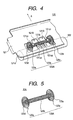
- Fig. 4 is a perspective view showing a key portion of another sheet feeding mechanism that is a second embodiment of the present invention.
- Fig. 5 is a perspective view showing another sheet-pressing member assembled into the sheet feeding mechanism constructed according to the third embodiment of the invention.
- a sheet feeding mechanism 120 as in the first embodiment, includes a sheet feed roller 122 and a sheet-pressing member 123.
- the sheet-pressing member 123 presses the slip sheet S against the sheet feed roller 122,
- the sheet-pressing member 123 is supported by a guide member 121 for guiding a slip sheet S.
- Two holes 121A and 121B are formed in the guide member 121 while being arrayed in the paper width direction.
- Claw-like pieces 121a1 and 121a2, and 121c1 and 121c2 are extended from the peripheral edges of the holes 121A and 121B.
- the claw-like pieces 121a1 and 121a2, and 121c1 and 121c2 support the side and upper portions of the sheet-pressing member 123.
- a coupling supports 121b is formed at a portion between the holes 121A and 121B.
- the sheet-pressing member 123 like the sheet-pressing member 23, includes a spring body 123A, which consists of a spring formed by spirally coiling a wire of stainless steel, for example.
- the sheet-pressing member 123 includes a cylindrical shaft portion 123b and pressing portions 123a and 123c, each shaped like a disc when viewed from the side, formed at both ends of the cylindrical shaft portion 123b.
- the shaft portion 23b is formed so that the wire rings formed are brought into close contact with one another by an initial tension.
- the pressing portions 123a and 123c are each formed like a spiral spring. Those portions 123a, 123b and 123c are formed with a single wire in an integral form.
- the pressing portions 123a and 123c of the sheet-pressing member 123 are each shaped like a cone of which the apex connects to the end of the cylindrical shaft portion 123b and the bottom surface is directed to the outside.
- the outside diameter of each of the pressing portions 123a and 123c is larger than that of the cylindrical shaft portion 123b.
- Contact portions 123d and 123e as the outermost circumferential edges of the pressing portions 123a and 123c are each formed with one or two wires so as to reduce the contact area where each of them contacts with the slip sheet S.
- the outer diameter of the pressing portion 123b is equal to that of the pressing portion 123c.
- the sheet-pressing member 123 may also be manufactured by a manufacturing method using an automatic coiling machine as in the above-mentioned embodiment.
- the shaft portion 123b of the sheet-pressing member 123 is grasped with the claw-like pieces 121a1 and 121a2, and 121c1 and 12c2, and the coupling support 121b1 of the guide member 121.
- the thus grasped sheet-pressing member 123 while being angularly immovable, is held with the guide member 121.
- the cylindrical shaft portion 123b of the sheet-pressing member 123 while being somewhat bent, are held between the claw-like pieces 121a1 and 121c1, whereby the sheet-pressing member 123 is immovable in the paper width direction.
- the contact portions 123d and 123e of the pressing portions 123a and 123bc of the sheet-pressing member 123 are protruded through the holes 121A and 121B of the guide member 121 to be in contact with the sheet feed roller 122, so that the shaft portion 123b is somewhat bent.
- the sheet-pressing member 123 of the second embodiment is also constructed such that the pressing portions 123a and 123c of large diameter flexibly press the slip sheet S against the sheet feed roller.
- their spring constant in the pressing direction may be set to be small when comparing with the conventional one. This fact implies that even if a dimensional variation of the manufactured sheet-pressing members 123, caused by their assembly accuracy difference and paper thickness difference, is relatively large, a variation of pressing forces of the sheet-pressing members, which impart onto the slip sheet S, is reduced.
- the pressing portions 123a and 123c, and the cylindrical shaft portion 23b supporting them, which are all used for the sheet-pressing by the sheet-pressing member 23, are integrally formed. This feature contributes to reduction of the number of required component parts and size reduction, and further easy assembling.
- the fourth embodiment is a printer incorporating a sheet-pressing member constructed according to the present invention.
- a printing unit 4 of the printer includes a carriage 40 which is movable along the guide shaft 6 in a direction X or in the direction opposite to the direction X.
- a printhead 4a is provided on the front side of the carriage 40.
- a nozzle face 41 occupies a central portion of the printhead 4a.
- Nozzle orifice array 42 is formed in this portion.
- the nozzle orifices eject ink drops at given timings in accordance with print information, and prints characters, for example, on a slip sheet S.
- a couple of sheet-pressing members 24 and 25 are respectively located upstream and downstream of the printhead 4a when viewed in the traveling direction X of the printhead 4a.
- the sheet-pressing members 24 and 25 are constructed with springs which are equal in construction.
- the sheet-pressing member 24 (25) includes a bar-like shaft portion 24a (25a), disc-like pressing portions 24b and 24c (25b and 25c) provided at both ends of the shaft portion 24a (25a) as in the embodiments already described, and a fixing portion 240 (250).
- the sheet-pressing member 24 (25) is fixedly attached, at its fixing portion 240 (250), to the carriage 40.
- each of the pressing portions 24b and 24c (25b and 25c) of the sheet-pressing member 24 (25) is larger than that of the shaft portion 24a (25a).
- the pressing portions 24b and 24c (25b and 25c) of the sheet-pressing member 24 (25) protrude beyond the nozzle face 41 of the printhead 4a so as to come in contact with the platen 10.
- the pressing portions 24b and 24c (25b and 25c) of the sheet-pressing member 24 (25) are respectively located at positions equally distanced from the nozzle orifice array 42.
- the sheet-pressing members 24 and 25 may also be manufactured by a manufacturing method using an automatic coiling machine, as in the embodiments mentioned above.
- the wiper 4c is provided while being oriented at a right angle to the guide shaft 6.
- the printing unit 4 is moved along the guide shaft 6 in the direction opposite to the direction X, while at the same time the wiper 4c is moved relatively to the printing unit 4 in the direction X, and wipes ink left on the nozzle orifice array 42 of the printhead 4a.
- the sheet-pressing members 24 and 25 are oriented in a direction Y perpendicular to the guide shaft 6.
- the pairs of the pressing portions 24b, 24c and 25b, 25c of the sheet-pressing members 24 and 25 are located on both sides of a region a including the nozzle orifice array 42 when viewed in the wiping direction (direction X) of the wiper 4c, viz., at positions out of the region a.
- the shaft portions 24a and 25a of the sheet-pressing members 24 and 25 are preferably selected so as to prevent those paired pressing portions 24b, 24c and 25b, 25c of the sheet-pressing members 24 and 25 from coming in contact with the wiper 4c when the wiper operates for wiping.
- the printer moves the slip sheet S in the direction Y while moving the printing unit 4 in the direction X.
- the slip sheet S is separated from the nozzle-orifice array 42 and pressed onto the platen 10 by the pressing portions 24b, 24c and 25b, 25c, which are located in the vicinity of the nozzle-orifice array 42.
- This structural feature prevents the slip sheet S, even if it is bent, from coming in contact with the nozzle face 41. As a result, no ink is transferred to the slip sheet S, and hence a high quality print is secured.
- the four pressing portions 24b, 24c and 25b, 25c are located at positions equally distanced from the nozzle-orifice array 42. This feature holds the slip sheet S in a well-balanced manner.
- pairs of the pressing portions 24b, 24c and 25b, 25c are located on both sides of the nozzle-orifice array 42 of the printhead 4a when viewed in the traveling direction (direction X) of the printhead 4a, and that those pairs of the pressing portions 24b, 24c and 25b, 25c are located on both sides of the slip sheet S when viewed in the sheet feeding direction Y.
- those pairs of the pressing portions 24b, 24c and 25b, 25c do not come in contact with the printed characters, for example, being still wet on the slip sheet S irrespective of the moving direction of the carriage 40. Therefore, the printer is free from the ink sticking problem arising from the rubbing of the printed slip sheet S with the sheet-pressing members 24 and 25.
- the nozzle face 41 is wiped with the wiper 4c in a manner that the carriage 40 is moved in the direction X and hence the wiper 4c is moved relatively to the printhead 4a.
- the pairs of the pressing portions 24b, 24c and 25b, 25c of the sheet-pressing members 24 and 25 are located at positions out of the region a including the nozzle-orifice array 42. Besides, there is no chance that the pairs of the pressing portions 24b, 24c and 25b, 25c of the sheet-pressing members 24 and 25 come into contact with the wiper 4c, and hence that the wiper 4c is worn with those members. No degradation of the wiping ability of the wiper 4c results.
- the present invention uses the sheet-pressing members 24 and 35 formed with spring members. Therefore, in design, their spring constant measured in the pressing direction may be set to be small when comparing with the conventional one. This entails reduction of a variation of pressing forces the sheet-pressing members impart onto the slip sheet S, and hence stable application of proper pressing forces to the slip sheet S and stable holding of the slip sheet S.
- the integrally formed sheet-pressing members 24 and 25 are fixed to the carriage 40. With this, a large space is not required, and the printer is simple in construction and reduced in size.
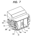
- FIG. 7 A fifth embodiment of the present invention will be described with reference to Fig. 7.
- like or equivalent portions are designated by like reference numerals in Fig. 6.
- a mounting member 260 is used for mounting sheet-pressing members 24 and 25 respectively on the upstream and downstream sides of the printhead 4a when viewed in the traveling direction X of the printhead 4a.
- the mounting member 260 is made of resin.
- two fins 262 and an arm 261 are formed at each end of the mounting member 260 when viewed in the longitudinal direction.
- the arm 261 is used for holding the central portion of the sheet-pressing member 24 (25).
- Each of the fins 262 includes a guide face slanted in the traveling direction of the printhead 4a. With provision of the guide faces of the fins 262, the printhead 4a may smoothly move to the slip sheet while not catching the end of the slip sheet. If the end of the slip sheet S is raised at a height longer than the radius of each of the pressing portions 24b and 24c, the end of the slip sheet is guided by the guide faces of the fins 262 and gradually held down on the platen 10 with the movement of the printhead 4a.
- Claw-like members 263 are provided on the other end of the mounting member 260. Holes 40a are formed in the carriage 40 at such locations as to receives the claw-like members 263 of the mounting member 260.
- the claw-like members 263 and the holes 40a form a so-called snap-fit construction.
- the sheet-pressing members 24 and 25 may easily be mounted on the printhead 4a.
- the guide portions for preventing the printhead 4a from catching the end of the slip sheet may be formed at both ends of the printhead 4a.
- a plurality of pressing portions may be provided at proper positions of the coil spring, which forms the shaft portion of the sheet-pressing member.
- the sheet-pressing members are held while being angularly immovable with respect to the guide member, it may be held while being angularly movable.
- the nozzle-orifice array 42 of the printhead is held at four points by use of two sheet-pressing members. So long as such a construction in which the pressing portions are provided at both ends of the region a is used, the sheet may be hold by use of two or a larger number of pressing portions. To hold down the recording member or sheet reliably and in a well-balanced manner, it is preferable to use the medium holding construction employed in the above-mentioned embodiments.
- sheet-pressing member constructed according to the invention may be applied to any mechanism requiring a stable pressure contact, in addition to the ink jet printer.
- the invention is most operant in particular when it is applied to a mechanism for transporting a sheet having printed characters, for example, being not yet fixed or still wet, as in the ink jet printer.
- the sheet feeding mechanism of the invention is able to impart an optimum pressing force onto a sheet being fed, and hence provides a printer of high quality printing.
Description
- The present invention relates to a pressing member as well as a sheet feeding mechanism and a printer using the pressing member as a sheet pressing member.
- To print by an ink jet printer, the nozzle orifices of a printhead selectively eject ink drops onto a printing paper in accordance with print information and synchronized with a relative movement of a printhead relative to a printing paper.
- Generally, to feed a printing paper in the printer, the printing paper is nipped by a pair of paper-feed rollers, and one of the paired rollers is rotated.
- In the case of the ink jet printer, characters, for example, printed on the printing paper are not fixed. Accordingly, when the printed paper is pressed against the rollers, ink of the printed characters is still wet. The wet ink sticks onto the roller, and is transferred from the roller to the sheet or paper.
- An ink jet printer designed to solve the ink sticking problem is disclosed in JP-A-2-41277. In this ink jet printer, the printing paper is pressed by an elastic pressing member against a paper feed roller. Therefore, the pressing member includes an elastic shaft portion and a spur gear like pressing portion with sharp teeth. The contact area between the pressing portion and the printing paper is small. Therefore, no ink transferred by the pressing portion to the printing paper. The pressing member has a large spring constant, and inevitably suffers from dimensional variations. For this reason, work to properly set a pressing force is very difficult. Where the pressing force is too large, an excessive load acts on the printing paper being fed. On the other hand, where it is too small, the paper feeding force is insufficient. Either case leads to degradation of print quality.
- GB-A-2 290 262 discloses a mechanism for paper handling in an ink jet printer in which pairs of sheet discharge rollers are provided and intermediate serrated rollers are provided between adjacent pairs. The intermediate rollers are each resiliently supported by a respective elastic shaft portion in the form of a rod spring.
- Accordingly, an object of the present invention is to provide a pressing member which imparts an optimum pressing force onto a sheet being transported. Another object of the invention is to provide a sheet feeding mechanism using the pressing member, and an ink jet printer using the sheet feeding mechanism.
- These objects are achieved with an pressing member as claimed in
claim 1, a sheet feeding mechanism as claimed inclaim 4, and a printer as claimed inclaim - The pressing member is constructed such that a pressing portion (e.g., a flat spiral spring) of large diameter flexibly presses a slip sheet against a sheet feed roller. With this feature, in design, a spring constant of it measured in the pressing direction may be set to be small when comparing with the conventional one.
- This fact implies that even if dimensional variation of the manufactured pressing members is relatively large, a variation of pressing forces which the pressing member imparts onto the slip sheet, is reduced.
- Thus, in the sheet feeding mechanism, an appropriate pressing force may stably be imparted onto the slip sheet by properly selecting such factors as the effective number of turns and the diameter of the shaft portion (also referred to as a coil portion hereinafter) of the pressing member, and the material of the pressing member.
- The pressing member takes an integral form. The feature of the integral form contributes to reduction of the number of required component parts and size reduction, and further easy assembling.
- Thus, the sheet feeding mechanism of the invention, which is simple in construction, can stably impart a pressing force of an optimum magnitude onto the sheet while being free from external factors such as assembling accuracy and medium or paper thickness.
- The ink jet printer equipped with the thus constructed sheet feeding mechanism succeeds in solving the wet-ink transfer problem in which ink is transferred from the sheet feeding mechanism to a printing paper immediately after it is printed, viz., the paper bearing printed characters, for example, which are still wet since it is not fixed. Further, the printer is capable of stably feeding the printing paper and hence printing at high print quality.
- Further with the ink jet printer according to the present invention the sheet, even if it is bent, does not come in contact with the nozzle face of the printhead since it is separated by the pressing members. Therefore, no ink is transferred to the slip sheet.
- The pressing portions do not come in contact with the printed characters being still wet on the sheet. Therefore, the printer is free from ink sticking problem arising from the rubbing of the sheet with the pressing members.
- Preferably the sheet is pressed down at a plurality of positions by use of the pressing portions, and hence the sheet is reliably held down.
- The thus constructed printer may include a wiper for wiping ink stuck onto the ink discharging orifices while moving relatively to the ink discharging orifices. The pressing members are located at positions out of a region including the ink discharging orifices when viewed in the wiping direction of the wiper. Therefore, there is no chance that the pairs of the pressing portions of the sheet-pressing members come in contact with the wiper means, and hence that the wiper is worn with those members. No degradation of the wiping ability of the wiper means results.
-
- Fig. 1
- is a perspective view showing an outline of an ink jet printer equipped with a sheet feeding mechanism that is a first embodiment of the present invention;
- Fig. 2
- is a perspective view showing a key portion of the sheet feeding mechanism of the first embodiment;
- Fig. 3
- is a perspective view showing a sheet-pressing member assembled into the sheet feeding mechanism of Fig. 2;
- Fig. 4
- is a perspective view showing a key portion of another sheet feeding mechanism that is a second embodiment of the invention;
- Fig. 5
- is a perspective view showing another sheet-pressing member assembled into the sheet feeding mechanism constructed according to a third embodiment of the invention;
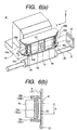
- Fig. 6
- is a perspective view showing a key portion of a fourth embodiment of a sheet-pressing member according to the present invention. Fig. 6A is a perspective view showing a printing unit of the printer of the fourth embodiment. Fig. 6B is a diagram showing a positional relationship between a nozzle face of a print head and a sheet-pressing member in the printer.
- Fig. 7
- is a perspective view showing a printing unit in a fifth embodiment of the invention.
- Preferred embodiments of the present invention will be described in detail with reference to the accompanying drawings.
- As shown in Fig. 1, in a
printer 1 constructed according to the invention, aprinting unit 4 is disposed in a front portion within amain body case 2. Theprinting unit 4 prints on a slip sheet S or a check sheet P referred to as a slip sheet S. Thecase 2 is made of resin. - The
printing unit 4 prints in a known ink jet printing manner. Theprinting unit 4 is movable along aguide shaft 6 within a limited range between both side ends of amain body frame 5 made of metal, for example. Theguide shaft 6 is transversely mounted on theframe 5. -
Pulleys frame 5. Anendless belt 7 is wound on thepulleys printing unit 4 is fastened to a part of theendless belt 7. - The
printing unit 4 is disposed such that aprinthead 4a of the printing unit is directed to the inside of thecase 2. - A
guide face 3 is disposed within thecase 2 while confronting theprinthead 4a of theprinting unit 4. Theguide face 3 is provided for guiding a slip sheet S. - A
platen 10 is located on the inner side of theguide face 3. A slip sheet S is moved through a gap between theplaten 10 and theprinthead 4a of theprinting unit 4. To print, theprinthead 4a ejects ink drops onto the slip sheet S moving through the gap. - A
cap 4b is provided adjacent to theplaten 10. When the printer rests for a predetermined time period or longer, theprinting unit 4 is moved to the position of thecap 4b to cover the nozzle orifices of theprinthead 4a with thecap 4b. With use of thecap 4b, the nozzles of theprinthead 4a can be kept wet even when the printer is left not used for a long time. - A
wiper 4c is further provided at a position near thecap 4b. Thewiper 4c is provided for wiping ink off the nozzie-orifice array 42 of theprinthead 4a. Thewiper 4c is formed with an elastic plate-like member made of resin, for example. - A paper-
insertion port 32 is formed in the front side of the main body of theprinter 1. Slip sheets S are inserted through the paper-insertion port 32 into the printer inside. A rail-like guide member 33 is extended along one of side ends of the paper-insertion port 32. The rail-like guide member 33 guides a slip sheet S when it is inserted into the printer through theport 32. - Paper transporting means 31 is provided within the main body of the
printer 1. The paper transporting means 31 transports a slip sheet S, which comes in through the paper-insertion port 32, toward theprinting unit 4. - The
paper transporting means 31 is constructed as follows: a couple of rotary shafts each having a plurality of rollers fixedly mounted thereon in a state that the rollers are spatially separated in the axial direction, are coupled such that the rollers of the shafts are aligned to form pairs of rollers each pair of rollers being in contact with each other. In Fig. 1, one roller shaft having a couple ofrollers 31 a mounted thereon is typically illustrated for simplicity of illustration. The roller shaft is oriented in a paper width direction, i.e., perpendicular to a sheet feeding direction A. - A plurality of
sheet feeding mechanisms 20, which will be described in detail later, are disposed in the upper portion of the printer main body, specifically at positions adjacent to theplaten 10 and located downstream when viewed in the sheet feeding direction A. Adischarge outlet 13 is located downstream of thesheet feeding mechanism 20 when viewed in the sheet feeding direction A. A printed slip sheet S is discharged through thedischarge outlet 13. - A roll paper R is located in the rear portion within the
main body case 2 of theprinter 1. Apaper exit port 12 is provided in the upper portion within thecase 2. The leading end of the roll paper R is led out of thepaper exit port 12. The roll paper R passes through a paper transporting path, which is different from a transporting path of the slip sheet S, although when the printer prints on the roll paper R, the roll paper R passes through the gap between theprinthead 4a of theprinting unit 4 and theplaten 10. - As shown in Figs. 1 and 2, each
sheet feeding mechanism 20 includes asheet feed roller 22 and a sheet-pressingmember 23. Thesheet feed roller 22 is coupled with a paper-feeding drive motor (not shown). The sheet-pressingmember 23 holds the slip sheet S being transported by pressing it down onto thesheet feed roller 22. The sheet-pressingmember 23 is supported by aguide member 21 for guiding a slip sheet S. - The
guide member 21 consists of a metal plate-like member shaped, by pressing, for example, to have an introducingportion 21 d and claw-like pieces 21 a. The introducingportion 21 d is provided for introducing the slip sheet S. The claw-like pieces 21a are for supporting and holding the sheet-pressingmember 23. Theguide member 21, which is mounted on theframe 5, is disposed along theguide face 3 of theprinter 1 and facing thesheet feed roller 22 with a predetermined space being present therebetween. - The introducing
portion 21d, which occupies an upstream end portion (when viewed in the sheet feeding direction A) of theguide member 21, is slanted in a direction in which its distance from theprinter guide face 3 increases. - Three
holes guide member 21 while being arrayed in the paper width direction. Claw-like pieces 21a1 and 21a2, and 21c1 and 21c2 are extended from the peripheral edges of theholes member 23. Coupling supports 21b1 and 21b2 are formed at portions between theholes holes - The sheet-pressing
member 23 includes a spring body, which consists of a spring by spirally coiling a wire of stainless steel, for example. Thespring body 23A of the sheet-pressingmember 23 includes a disc-likepressing portion 23a andcylindrical shaft portions pressing portion 23a. Thepressing portion 23a, occupying the central portion of the spring body, is formed like a spiral spring. Theshaft portions portions - As shown in Fig. 3, the
pressing portion 23a of the sheet-pressingmember 23 is shaped like a disc when viewed from the side. It takes the form of a body formed by coupling together two cones together such that the bottom surfaces of them are in contact with each other. The outside diameter of thepressing portion 23a is larger than that of thecylindrical shaft portions contact portion 23d as the outermost circumferential edge of thepressing portion 23a is formed with one or two wires so as to reduce the contact area where it contacts with the slip sheet S. In the embodiment, the diameter of thecylindrical shaft portion 23b is selected to be equal to that of theshaft portion 23c. - The sheet-pressing
member 23 may be manufactured by a manufacturing method using an automatic coiling machine. - The manufacturing process is a coiling method in which a wire for a coil spring travels tracing a predetermined path while being fed by a feed roller, and during the travel of the wire, it is curved at a predetermined curvature and twisted at a predetermined torsion. The diameter of a coil is varied by changing a position of a coiling pin set in the width of the wire traveling path.
- In the method for manufacturing the sheet-pressing member employed, a coiling pin (not shown) is fixed to a predetermined position. One
shaft portion 23b is first formed. Then, pressingportion 23a, larger in diameter than theshaft portion 23b, is formed in a manner that the coiling pin is gradually moved apart from the axial center of the coil, and then moved toward the axial center of the coil. Subsequently, the coiling pin is fixed at a predetermined position (the same position as the position used for forming theshaft portion 23b), and theother shaft portion 23c is formed in a similar manner. - As shown in Fig. 2, one
shaft portion 23b of the sheet-pressingmember 23 is grasped with the claw-like pieces 21a1 and 21a2, and the coupling support 21b1, while theother shaft portion 23c is grasped with the claw-like pieces 21c1 and 21c2, and the coupling support 21b2. The thus grasped sheet-pressingmember 23, while being angularly immovable, is held with theguide member 21. - The
cylindrical shaft portions member 23, which are thus held, are somewhat bent, by the coupling support 21b1, between the claw-like pieces 21a1 and 21c1, whereby the sheet-pressingmember 23 is immovable in the paper width direction. - The
contact portion 23d of thepressing portion 23a of the sheet-pressingmember 23 is protruded through thehole 21 B of theguide member 21 to be in contact with thesheet feed roller 22, so that theshaft portions - The sheet feeding mechanism for an ink jet printer is thus constructed. In operation, after subjected to printing by the
printhead 4a in theprinter 1, a slip sheet S is transported by thepaper transporting means 31; guided by the introducingportion 21d of theguide member 21; and inserted into the space between thesheet feed roller 22 and thepressing portion 23a of the sheet-pressingmember 23. - The
pressing portion 23a presses the slip sheet S against thesheet feed roller 22, and is transported to thedischarge outlet 13 with rotation of thesheet feed roller 22. - The
contact portion 23d of thepressing portion 23a is designed so as to have a small contact area where it contacts with the slip sheet S. Because of this, little ink is transferred to the slip sheet S during the sheet feeding. - The sheet-pressing
member 23 is constructed such that thepressing portion 23a of large diameter flexibly presses the slip sheet S against the sheet feed roller. With this feature, in design, a spring constant of it, measured in the pressing direction, may be set to be small when comparing with the conventional one. - This fact implies that even if a dimensional variation of the manufactured sheet-pressing
members 23, caused by their assembly accuracy difference and paper thickness difference, is relatively large, a variation of pressing forces, the sheet-pressing members impart onto the slip sheet S, is reduced. - Thus, the sheet-pressing member of the invention is capable of stably imparting an appropriate pressing force on the slip sheet S through a designer's proper selection of such factors as the effective number of turns and the diameter of the shaft portion of the sheet-pressing
member 23, and the material of the sheet-pressing member. In this respect, improved print quality results. - It is noted that the
pressing portion 23a, and thecylindrical shaft portions member 23, are integrally formed. This feature contributes to reduction of the number of required component parts and size reduction, and further easy assembling. - Further, a plurality of sheet-pressing
members 23 are arrayed in the paper width direction. Therefore, the sheet feeding mechanism can stably feed slip sheets S of different width dimensions. - Fig. 4 is a perspective view showing a key portion of another sheet feeding mechanism that is a second embodiment of the present invention. Fig. 5 is a perspective view showing another sheet-pressing member assembled into the sheet feeding mechanism constructed according to the third embodiment of the invention.
- As shown in Fig. 4, a
sheet feeding mechanism 120, as in the first embodiment, includes asheet feed roller 122 and a sheet-pressing member 123. The sheet-pressing member 123 presses the slip sheet S against thesheet feed roller 122, The sheet-pressing member 123 is supported by aguide member 121 for guiding a slip sheet S. - Two
holes guide member 121 while being arrayed in the paper width direction. Claw-like pieces 121a1 and 121a2, and 121c1 and 121c2 are extended from the peripheral edges of theholes holes - The sheet-pressing member 123, like the sheet-pressing
member 23, includes aspring body 123A, which consists of a spring formed by spirally coiling a wire of stainless steel, for example. - As shown in Fig. 5, the sheet-pressing member 123 includes a
cylindrical shaft portion 123b andpressing portions cylindrical shaft portion 123b. Theshaft portion 23b is formed so that the wire rings formed are brought into close contact with one another by an initial tension. - The
pressing portions portions - As shown in Fig. 5, the
pressing portions cylindrical shaft portion 123b and the bottom surface is directed to the outside. The outside diameter of each of thepressing portions cylindrical shaft portion 123b. -
Contact portions pressing portions pressing portion 123b is equal to that of thepressing portion 123c. - The sheet-pressing member 123 may also be manufactured by a manufacturing method using an automatic coiling machine as in the above-mentioned embodiment.
- As shown in Fig. 4, the
shaft portion 123b of the sheet-pressing member 123 is grasped with the claw-like pieces 121a1 and 121a2, and 121c1 and 12c2, and the coupling support 121b1 of theguide member 121. The thus grasped sheet-pressing member 123, while being angularly immovable, is held with theguide member 121. - The
cylindrical shaft portion 123b of the sheet-pressing member 123, while being somewhat bent, are held between the claw-like pieces 121a1 and 121c1, whereby the sheet-pressing member 123 is immovable in the paper width direction. - The
contact portions pressing portions 123a and 123bc of the sheet-pressing member 123 are protruded through theholes guide member 121 to be in contact with thesheet feed roller 122, so that theshaft portion 123b is somewhat bent. - The sheet-pressing member 123 of the second embodiment is also constructed such that the
pressing portions - The
pressing portions cylindrical shaft portion 23b supporting them, which are all used for the sheet-pressing by the sheet-pressingmember 23, are integrally formed. This feature contributes to reduction of the number of required component parts and size reduction, and further easy assembling. - A fourth embodiment of the present invention will be described with reference to Fig. 6. The fourth embodiment is a printer incorporating a sheet-pressing member constructed according to the present invention.
- As shown in Fig. 6A, a
printing unit 4 of the printer includes acarriage 40 which is movable along theguide shaft 6 in a direction X or in the direction opposite to the direction X. Aprinthead 4a is provided on the front side of thecarriage 40. Anozzle face 41 occupies a central portion of theprinthead 4a.Nozzle orifice array 42 is formed in this portion. To print, the nozzle orifices eject ink drops at given timings in accordance with print information, and prints characters, for example, on a slip sheet S. - A couple of sheet-pressing
members printhead 4a when viewed in the traveling direction X of theprinthead 4a. The sheet-pressingmembers like shaft portion 24a (25a), disc-likepressing portions shaft portion 24a (25a) as in the embodiments already described, and a fixing portion 240 (250). The sheet-pressing member 24 (25) is fixedly attached, at its fixing portion 240 (250), to thecarriage 40. - The outside diameter of each of the
pressing portions shaft portion 24a (25a). As shown in Fig. 6B, thepressing portions nozzle face 41 of theprinthead 4a so as to come in contact with theplaten 10. - The
pressing portions nozzle orifice array 42. - The sheet-pressing
members - As shown in Fig. 6A, the
wiper 4c is provided while being oriented at a right angle to theguide shaft 6. In operation, theprinting unit 4 is moved along theguide shaft 6 in the direction opposite to the direction X, while at the same time thewiper 4c is moved relatively to theprinting unit 4 in the direction X, and wipes ink left on thenozzle orifice array 42 of theprinthead 4a. - In the present embodiment, the sheet-pressing
members guide shaft 6. - As shown in Figs. 6A and 6B, the pairs of the
pressing portions members nozzle orifice array 42 when viewed in the wiping direction (direction X) of thewiper 4c, viz., at positions out of the region a. - In this case, the
shaft portions members pressing portions members wiper 4c when the wiper operates for wiping. - In a printing operation, the printer moves the slip sheet S in the direction Y while moving the
printing unit 4 in the direction X. - In this case, as shown in Fig. 6B, the slip sheet S is separated from the nozzle-
orifice array 42 and pressed onto theplaten 10 by thepressing portions orifice array 42. This structural feature prevents the slip sheet S, even if it is bent, from coming in contact with thenozzle face 41. As a result, no ink is transferred to the slip sheet S, and hence a high quality print is secured. - Further, it is noted that the four
pressing portions orifice array 42. This feature holds the slip sheet S in a well-balanced manner. - Furthermore, it is noted that the pairs of the
pressing portions orifice array 42 of theprinthead 4a when viewed in the traveling direction (direction X) of theprinthead 4a, and that those pairs of thepressing portions pressing portions carriage 40. Therefore, the printer is free from the ink sticking problem arising from the rubbing of the printed slip sheet S with the sheet-pressingmembers - Also in the embodiment, as shown Fig. 6A, the
nozzle face 41 is wiped with thewiper 4c in a manner that thecarriage 40 is moved in the direction X and hence thewiper 4c is moved relatively to theprinthead 4a. - In connection with this, the pairs of the
pressing portions members orifice array 42. Besides, there is no chance that the pairs of thepressing portions members wiper 4c, and hence that thewiper 4c is worn with those members. No degradation of the wiping ability of thewiper 4c results. - Additionally, the present invention uses the sheet-pressing
members 24 and 35 formed with spring members. Therefore, in design, their spring constant measured in the pressing direction may be set to be small when comparing with the conventional one. This entails reduction of a variation of pressing forces the sheet-pressing members impart onto the slip sheet S, and hence stable application of proper pressing forces to the slip sheet S and stable holding of the slip sheet S. - The integrally formed sheet-pressing
members carriage 40. With this, a large space is not required, and the printer is simple in construction and reduced in size. - A fifth embodiment of the present invention will be described with reference to Fig. 7. In the figure, like or equivalent portions are designated by like reference numerals in Fig. 6.
- A mounting
member 260 is used for mounting sheet-pressingmembers printhead 4a when viewed in the traveling direction X of theprinthead 4a. The mountingmember 260 is made of resin. As shown, twofins 262 and anarm 261 are formed at each end of the mountingmember 260 when viewed in the longitudinal direction. Thearm 261 is used for holding the central portion of the sheet-pressing member 24 (25). - Each of the
fins 262 includes a guide face slanted in the traveling direction of theprinthead 4a. With provision of the guide faces of thefins 262, theprinthead 4a may smoothly move to the slip sheet while not catching the end of the slip sheet. If the end of the slip sheet S is raised at a height longer than the radius of each of thepressing portions fins 262 and gradually held down on theplaten 10 with the movement of theprinthead 4a. - Claw-
like members 263 are provided on the other end of the mountingmember 260.Holes 40a are formed in thecarriage 40 at such locations as to receives the claw-like members 263 of the mountingmember 260. The claw-like members 263 and theholes 40a form a so-called snap-fit construction. With this construction of the mountingmember 260, the sheet-pressingmembers printhead 4a. Further, the guide portions for preventing theprinthead 4a from catching the end of the slip sheet may be formed at both ends of theprinthead 4a. - It should be understood by those skilled in the art that the present invention is not limited to the above-mentioned embodiments, but may variously be changed, modified and altered.
- For example, a plurality of pressing portions may be provided at proper positions of the coil spring, which forms the shaft portion of the sheet-pressing member.
- While in the above-mentioned embodiments, the sheet-pressing members are held while being angularly immovable with respect to the guide member, it may be held while being angularly movable.
- In the fourth and fifth embodiments, the nozzle-
orifice array 42 of the printhead is held at four points by use of two sheet-pressing members. So long as such a construction in which the pressing portions are provided at both ends of the region a is used, the sheet may be hold by use of two or a larger number of pressing portions. To hold down the recording member or sheet reliably and in a well-balanced manner, it is preferable to use the medium holding construction employed in the above-mentioned embodiments. - While two pressing members are formed at both ends of the coil spring of the sheet-pressing member in the fourth and fifth embodiments, three or a larger number of pressing portions may be formed on one spring coil.
- Additionally, it is evident that the sheet-pressing member constructed according to the invention may be applied to any mechanism requiring a stable pressure contact, in addition to the ink jet printer.
- The invention is most operant in particular when it is applied to a mechanism for transporting a sheet having printed characters, for example, being not yet fixed or still wet, as in the ink jet printer.
- As seen from the foregoing description, the sheet feeding mechanism of the invention is able to impart an optimum pressing force onto a sheet being fed, and hence provides a printer of high quality printing.
Claims (9)
- A pressing member for pressing an object being transported along a transport path, said pressing member (23; 123) including a cylindrical shaft portion (23b, 23c; 123b) formed by coiling an elastic wire into wire rings of substantially constant diameter about a central axis so that the wire rings are brought into close contact with one another, and a pressing portion (23a; 123a) formed by spirally coiling said wire to an outer diameter larger than the diameter of the shaft portion.
- The pressing member according to claim 1, wherein said pressing portion (23a) is provided at the middle of said shaft portion (23b, 23c) in the axial direction of the latter.
- The pressing member according to claim 1, wherein two pressing portions (123a) are provided, one at each end of said shaft portion (123b).
- A sheet feeding mechanism for feeding a sheet along a transport path, comprising:a sheet feed roller (22; 122); andthe pressing member (23; 123) as defined in any one of claims 1 to 3 disposed so that said pressing portion (23a; 123a) is pressed against said sheet feed roller.
- A printer for printing on a sheet set therein, said printer comprising:a printhead (4a); anda sheet feeding mechanism as defined in claim 4, wherein the sheet feed roller (22; 122) is disposed downward of said printhead when viewed in the sheet feeding direction, for feeding a sheet printed by said printhead in said sheet feeding direction.
- A printer according to claim 5, wherein said printhead (4a) is of an ink jet type.
- A printer comprising:a printhead (4a) for printing characters on a sheet moving relatively to the printhead by ejecting ink drops through ink discharging orifices (42); andpressing members (24, 25) as defined in any one of claims 1 to 3, wherein the pressing portions (24b, 24c, 25b, 25c) are located near to but spaced apart from said discharging orifices (42) for pressing on the sheet at positions where they do not get into contact with the ink of the just printed characters.
- A printer according to claim 7 using pressing members as defined in claim 3, wherein said pressing portions (24b, 24c, 25b, 25c) are arranged for pressing down both sides of a region on the sheet immediately after characters are printed on the sheet.
- A printer according to claim 7 or 8 using pressing members as defined in claim 3, further comprising: a wiper (4c) for wiping ink stuck onto said ink discharging orifices while moving relatively to said ink discharging orifices (42), wherein the pressing portions (24b, 24c, 25b, 25c) of said pressing members are located at positions out of a region including said ink discharging orifices when viewed in the wiping direction of said wiper.
Applications Claiming Priority (4)
| Application Number | Priority Date | Filing Date | Title |
|---|---|---|---|
| JP9776198 | 1998-04-09 | ||
| JP9776198 | 1998-04-09 | ||
| JP12377198A JP3653982B2 (en) | 1998-05-06 | 1998-05-06 | Inkjet printer |
| JP12377198 | 1998-05-06 |
Publications (2)
| Publication Number | Publication Date |
|---|---|
| EP0949082A1 EP0949082A1 (en) | 1999-10-13 |
| EP0949082B1 true EP0949082B1 (en) | 2002-09-04 |
Family
ID=26438911
Family Applications (1)
| Application Number | Title | Priority Date | Filing Date |
|---|---|---|---|
| EP99106928A Expired - Lifetime EP0949082B1 (en) | 1998-04-09 | 1999-04-08 | Sheet-pressing member for sheet feeder mechanism |
Country Status (7)
| Country | Link |
|---|---|
| US (1) | US6299367B1 (en) |
| EP (1) | EP0949082B1 (en) |
| KR (1) | KR100476830B1 (en) |
| CN (1) | CN1205049C (en) |
| CA (1) | CA2268471C (en) |
| DE (1) | DE69902710T2 (en) |
| HK (1) | HK1023315A1 (en) |
Cited By (1)
| Publication number | Priority date | Publication date | Assignee | Title |
|---|---|---|---|---|
| US7275742B2 (en) | 2003-07-24 | 2007-10-02 | Heidelberger Druckmaschinen Ag | Apparatus with springs for conveying sheets in a printing press |
Families Citing this family (13)
| Publication number | Priority date | Publication date | Assignee | Title |
|---|---|---|---|---|
| US6547464B1 (en) * | 1999-12-01 | 2003-04-15 | Diebòld, Incorporated | Automated transaction machine printer |
| JP2005247546A (en) * | 2004-03-05 | 2005-09-15 | Brother Ind Ltd | Eject roller, transporting device, and ink jet recording device |
| US7309357B2 (en) * | 2004-12-30 | 2007-12-18 | Infinesse, Corporation | Prosthetic spinal discs |
| JP4743428B2 (en) * | 2006-08-03 | 2011-08-10 | セイコーエプソン株式会社 | Recording device |
| CN101312477B (en) * | 2007-05-25 | 2010-06-02 | 东友科技股份有限公司 | Automatic paper feeding apparatus and transaction machine suitable for the same |
| DE102007043904A1 (en) * | 2007-09-14 | 2009-03-19 | Osram Gesellschaft mit beschränkter Haftung | Luminous device |
| US20090157185A1 (en) * | 2007-12-18 | 2009-06-18 | Chong Chol Kim | Prosthetic Monolithic Spinal Discs and Method of Customizing and Constructing Discs |
| JP5444621B2 (en) * | 2008-02-26 | 2014-03-19 | 株式会社リコー | Stencil printing machine |
| JP6383196B2 (en) * | 2014-07-02 | 2018-08-29 | グラフテック株式会社 | Cutting plotter |
| JP6520528B2 (en) * | 2015-07-29 | 2019-05-29 | セイコーエプソン株式会社 | Printing device |
| CN108001050B (en) * | 2016-10-28 | 2020-03-13 | 惠普发展公司有限责任合伙企业 | Adjusting print media acquisition |
| JP6874703B2 (en) * | 2018-01-31 | 2021-05-19 | ブラザー工業株式会社 | Sheet transfer device |
| JP7267774B2 (en) * | 2019-02-28 | 2023-05-02 | キヤノン株式会社 | image forming device |
Family Cites Families (16)
| Publication number | Priority date | Publication date | Assignee | Title |
|---|---|---|---|---|
| US274715A (en) * | 1883-03-27 | buckley | ||
| US653155A (en) * | 1900-03-26 | 1900-07-03 | Marshall Tilden | Coil-spring. |
| US1462925A (en) * | 1921-12-12 | 1923-07-24 | Wilburger William | Spring binder post |
| US1963053A (en) * | 1933-08-14 | 1934-06-12 | Powers Spring Corp | Wire spring |
| US2852801A (en) * | 1956-08-08 | 1958-09-23 | Christian F Kleinknecht | Door stop |
| DE2506420C3 (en) * | 1975-02-15 | 1982-03-11 | Gebrüder Ahle, 5253 Lindlar | Non-cylindrical, coiled compression spring made of wire with a circular cross-section, in particular for use in motor vehicles |
| JP2643963B2 (en) | 1987-12-29 | 1997-08-25 | キヤノン株式会社 | Printer recording member transporter |
| JP2821747B2 (en) * | 1988-08-01 | 1998-11-05 | キヤノン株式会社 | Inkjet printer |
| EP0732216B1 (en) * | 1989-09-18 | 2000-05-31 | Canon Kabushiki Kaisha | An ink jet recording apparatus |
| JPH06255119A (en) | 1993-03-09 | 1994-09-13 | Canon Inc | Ink jet recording apparatus |
| JP3320149B2 (en) | 1993-06-21 | 2002-09-03 | 株式会社東芝 | Paper ejection device |
| JPH07101588A (en) | 1993-10-01 | 1995-04-18 | Canon Inc | Recording device |
| GB2285777A (en) | 1994-01-25 | 1995-07-26 | Bride David James Mc | Spring wheel |
| GB2290262B (en) | 1994-02-10 | 1996-09-04 | Seiko Epson Corp | Ink jet printer |
| JPH08133545A (en) | 1994-11-14 | 1996-05-28 | Ricoh Co Ltd | Paper feeding roller |
| US5868383A (en) * | 1997-03-27 | 1999-02-09 | L&P Property Management Company | Multiple rate coil spring assembly |
-
1999
- 1999-04-08 EP EP99106928A patent/EP0949082B1/en not_active Expired - Lifetime
- 1999-04-08 CA CA002268471A patent/CA2268471C/en not_active Expired - Fee Related
- 1999-04-08 DE DE69902710T patent/DE69902710T2/en not_active Expired - Lifetime
- 1999-04-08 US US09/288,170 patent/US6299367B1/en not_active Expired - Fee Related
- 1999-04-09 CN CNB99106058XA patent/CN1205049C/en not_active Expired - Fee Related
- 1999-04-09 KR KR10-1999-0012444A patent/KR100476830B1/en not_active IP Right Cessation
-
2000
- 2000-04-27 HK HK00102550A patent/HK1023315A1/en not_active IP Right Cessation
Cited By (1)
| Publication number | Priority date | Publication date | Assignee | Title |
|---|---|---|---|---|
| US7275742B2 (en) | 2003-07-24 | 2007-10-02 | Heidelberger Druckmaschinen Ag | Apparatus with springs for conveying sheets in a printing press |
Also Published As
| Publication number | Publication date |
|---|---|
| CA2268471C (en) | 2007-12-04 |
| CA2268471A1 (en) | 1999-10-09 |
| DE69902710D1 (en) | 2002-10-10 |
| US6299367B1 (en) | 2001-10-09 |
| CN1205049C (en) | 2005-06-08 |
| EP0949082A1 (en) | 1999-10-13 |
| KR100476830B1 (en) | 2005-03-18 |
| DE69902710T2 (en) | 2003-08-07 |
| CN1235093A (en) | 1999-11-17 |
| HK1023315A1 (en) | 2000-09-08 |
| KR19990083066A (en) | 1999-11-25 |
Similar Documents
| Publication | Publication Date | Title |
|---|---|---|
| US5564847A (en) | Media handling in an ink-jet printer having guide ribs | |
| EP0949082B1 (en) | Sheet-pressing member for sheet feeder mechanism | |
| US5419644A (en) | Print medium handling system including cockle springs to control pen-to-print medium spacing during printing | |
| US5805176A (en) | Ink jet printer and device for insuring proper printing | |
| EP1661837B1 (en) | Sheet discharge system | |
| US7618139B2 (en) | Printer having improved recording medium feeding mechanism | |
| EP1595833B1 (en) | Recording device | |
| EP0729842B1 (en) | Media handling in an ink-jet printer | |
| US6786663B2 (en) | Recording apparatus | |
| JP3922336B2 (en) | Flap holding member and recording apparatus provided with the member | |
| JP3812643B2 (en) | Conveyor driven roller mounting device | |
| GB2290262A (en) | Paper handling in ink jet printer. | |
| JPH05124284A (en) | Ink jet printer | |
| JP3653982B2 (en) | Inkjet printer | |
| JPH11349178A (en) | Paper restraint member and paper feeding mechanism using the member and printer using it | |
| JP3775478B2 (en) | Discharged driven roller mounting device | |
| US20080251985A1 (en) | Driven roller, transport roller device, and liquid ejecting apparatus | |
| KR970006746Y1 (en) | Sheet bail apparatus | |
| JP3287212B2 (en) | Inkjet printer | |
| JPS6262782A (en) | Sheet conveyor for printer | |
| JP3574291B2 (en) | Printer paper holding mechanism | |
| JP2014124869A (en) | Printer | |
| JP4006586B2 (en) | Toothed roller support device and recording device | |
| KR20040087496A (en) | Feeding apparatus of printer | |
| JPH08217305A (en) | Ink jet printer |
Legal Events
| Date | Code | Title | Description |
|---|---|---|---|
| PUAI | Public reference made under article 153(3) epc to a published international application that has entered the european phase |
Free format text: ORIGINAL CODE: 0009012 |
|
| AK | Designated contracting states |
Kind code of ref document: A1 Designated state(s): CH DE FR GB IT LI |
|
| AX | Request for extension of the european patent |
Free format text: AL;LT;LV;MK;RO;SI |
|
| 17P | Request for examination filed |
Effective date: 20000330 |
|
| AKX | Designation fees paid |
Free format text: CH DE FR GB IT LI |
|
| 17Q | First examination report despatched |
Effective date: 20001005 |
|
| GRAG | Despatch of communication of intention to grant |
Free format text: ORIGINAL CODE: EPIDOS AGRA |
|
| GRAG | Despatch of communication of intention to grant |
Free format text: ORIGINAL CODE: EPIDOS AGRA |
|
| GRAH | Despatch of communication of intention to grant a patent |
Free format text: ORIGINAL CODE: EPIDOS IGRA |
|
| GRAH | Despatch of communication of intention to grant a patent |
Free format text: ORIGINAL CODE: EPIDOS IGRA |
|
| GRAA | (expected) grant |
Free format text: ORIGINAL CODE: 0009210 |
|
| AK | Designated contracting states |
Kind code of ref document: B1 Designated state(s): CH DE FR GB IT LI |
|
| REG | Reference to a national code |
Ref country code: GB Ref legal event code: FG4D |
|
| REG | Reference to a national code |
Ref country code: CH Ref legal event code: EP |
|
| REG | Reference to a national code |
Ref country code: CH Ref legal event code: NV Representative=s name: BOVARD AG PATENTANWAELTE |
|
| REF | Corresponds to: |
Ref document number: 69902710 Country of ref document: DE Date of ref document: 20021010 |
|
| ET | Fr: translation filed | ||
| PLBE | No opposition filed within time limit |
Free format text: ORIGINAL CODE: 0009261 |
|
| STAA | Information on the status of an ep patent application or granted ep patent |
Free format text: STATUS: NO OPPOSITION FILED WITHIN TIME LIMIT |
|
| 26N | No opposition filed |
Effective date: 20030605 |
|
| PGFP | Annual fee paid to national office [announced via postgrant information from national office to epo] |
Ref country code: CH Payment date: 20100414 Year of fee payment: 12 |
|
| REG | Reference to a national code |
Ref country code: CH Ref legal event code: PFA Owner name: SEIKO EPSON CORPORATION Free format text: SEIKO EPSON CORPORATION#4-1, NISHISHINJUKU 2-CHOME#SHINJUKU-KU, TOKYO 163-0811 (JP) -TRANSFER TO- SEIKO EPSON CORPORATION#4-1, NISHISHINJUKU 2-CHOME#SHINJUKU-KU, TOKYO 163-0811 (JP) |
|
| PGFP | Annual fee paid to national office [announced via postgrant information from national office to epo] |
Ref country code: FR Payment date: 20110426 Year of fee payment: 13 Ref country code: DE Payment date: 20110406 Year of fee payment: 13 |
|
| PGFP | Annual fee paid to national office [announced via postgrant information from national office to epo] |
Ref country code: GB Payment date: 20110406 Year of fee payment: 13 |
|
| PGFP | Annual fee paid to national office [announced via postgrant information from national office to epo] |
Ref country code: IT Payment date: 20110418 Year of fee payment: 13 |
|
| REG | Reference to a national code |
Ref country code: CH Ref legal event code: PL |
|
| PG25 | Lapsed in a contracting state [announced via postgrant information from national office to epo] |
Ref country code: LI Free format text: LAPSE BECAUSE OF NON-PAYMENT OF DUE FEES Effective date: 20110430 Ref country code: CH Free format text: LAPSE BECAUSE OF NON-PAYMENT OF DUE FEES Effective date: 20110430 |
|
| GBPC | Gb: european patent ceased through non-payment of renewal fee |
Effective date: 20120408 |
|
| REG | Reference to a national code |
Ref country code: FR Ref legal event code: ST Effective date: 20121228 |
|
| PG25 | Lapsed in a contracting state [announced via postgrant information from national office to epo] |
Ref country code: GB Free format text: LAPSE BECAUSE OF NON-PAYMENT OF DUE FEES Effective date: 20120408 |
|
| REG | Reference to a national code |
Ref country code: DE Ref legal event code: R119 Ref document number: 69902710 Country of ref document: DE Effective date: 20121101 |
|
| PG25 | Lapsed in a contracting state [announced via postgrant information from national office to epo] |
Ref country code: IT Free format text: LAPSE BECAUSE OF NON-PAYMENT OF DUE FEES Effective date: 20120408 Ref country code: FR Free format text: LAPSE BECAUSE OF NON-PAYMENT OF DUE FEES Effective date: 20120430 |
|
| PG25 | Lapsed in a contracting state [announced via postgrant information from national office to epo] |
Ref country code: DE Free format text: LAPSE BECAUSE OF NON-PAYMENT OF DUE FEES Effective date: 20121101 |