EP0948114A2 - Electrical switching apparatus - Google Patents
Electrical switching apparatus Download PDFInfo
- Publication number
- EP0948114A2 EP0948114A2 EP99302452A EP99302452A EP0948114A2 EP 0948114 A2 EP0948114 A2 EP 0948114A2 EP 99302452 A EP99302452 A EP 99302452A EP 99302452 A EP99302452 A EP 99302452A EP 0948114 A2 EP0948114 A2 EP 0948114A2
- Authority
- EP
- European Patent Office
- Prior art keywords
- control unit
- remote control
- switch
- switching
- control device
- Prior art date
- Legal status (The legal status is an assumption and is not a legal conclusion. Google has not performed a legal analysis and makes no representation as to the accuracy of the status listed.)
- Withdrawn
Links
- 241000220317 Rosa Species 0.000 claims description 2
- 239000004020 conductor Substances 0.000 claims description 2
- 238000005192 partition Methods 0.000 abstract description 7
- 238000010586 diagram Methods 0.000 description 3
- 229920003023 plastic Polymers 0.000 description 3
- 239000004033 plastic Substances 0.000 description 3
- 239000011800 void material Substances 0.000 description 3
- 230000000994 depressogenic effect Effects 0.000 description 2
- 230000000694 effects Effects 0.000 description 2
- 239000011521 glass Substances 0.000 description 2
- 230000007935 neutral effect Effects 0.000 description 2
- 238000010276 construction Methods 0.000 description 1
- 238000009434 installation Methods 0.000 description 1
- 230000000717 retained effect Effects 0.000 description 1
- 239000013589 supplement Substances 0.000 description 1
Images


Classifications
-
- H—ELECTRICITY
- H05—ELECTRIC TECHNIQUES NOT OTHERWISE PROVIDED FOR
- H05B—ELECTRIC HEATING; ELECTRIC LIGHT SOURCES NOT OTHERWISE PROVIDED FOR; CIRCUIT ARRANGEMENTS FOR ELECTRIC LIGHT SOURCES, IN GENERAL
- H05B47/00—Circuit arrangements for operating light sources in general, i.e. where the type of light source is not relevant
- H05B47/10—Controlling the light source
- H05B47/175—Controlling the light source by remote control
-
- G—PHYSICS
- G08—SIGNALLING
- G08C—TRANSMISSION SYSTEMS FOR MEASURED VALUES, CONTROL OR SIMILAR SIGNALS
- G08C19/00—Electric signal transmission systems
- G08C19/16—Electric signal transmission systems in which transmission is by pulses
- G08C19/28—Electric signal transmission systems in which transmission is by pulses using pulse code
-
- G—PHYSICS
- G08—SIGNALLING
- G08C—TRANSMISSION SYSTEMS FOR MEASURED VALUES, CONTROL OR SIMILAR SIGNALS
- G08C23/00—Non-electrical signal transmission systems, e.g. optical systems
- G08C23/04—Non-electrical signal transmission systems, e.g. optical systems using light waves, e.g. infrared
-
- G—PHYSICS
- G08—SIGNALLING
- G08C—TRANSMISSION SYSTEMS FOR MEASURED VALUES, CONTROL OR SIMILAR SIGNALS
- G08C2201/00—Transmission systems of control signals via wireless link
- G08C2201/20—Binding and programming of remote control devices
Definitions
- This invention relates to switching apparatus for controlling electrical loads, such as lights.
- Lights in dwellings and other buildings are generally controlled by a wall-mounted switch, which is arranged in the lighting circuit to physically connect or disconnect wires that extend between the mains supply and the light.
- wires are installed during construction of the dwelling etc., so that they are hidden from view.
- Another disadvantage of adding switches is that the existing switch needs to be wired in a special manner, otherwise the switches will work independently of each other, thereby creating the problem that the light cannot be turned off, except from the switch that was used to turn it on.
- an electrical switching apparatus comprising a remote control device which can be actuated to transmit a wireless control signal and a control unit having a receiver for receiving said signal, a switching device for connecting in series between a load to be switched and a current supply, a switch terminal for connecting to a conductor extending from a remote switch, and control means for changing the switching state of said switching device, either when a change is detected in a signal on said switch terminal or when said wireless control signal is received by said receiver.
- the apparatus can be configured to provide an additional switch point for an existing switched light by disconnecting the light from the remote existing switch and connecting the control unit, such that the switching device of the unit is arranged in series between the light and the mains supply.
- the wire from the existing remote switch can then be connected to the switch terminal of the control unit.
- the state of the switching device can be changed either by actuating the remote control device to transmit said wireless control signal or by actuating the existing remote switch. Accordingly, the light is turned on when either the remote control device or the existing switch are actuated.
- the state of the switching device can be changed back to its original state either by actuating the remote control device or the existing switch.
- the remote control device provides a further point at which the light can be turned on or off, either in addition to or instead of the existing switch.
- the apparatus enables the light to be turned off either by the existing switch or the remote control device, regardless of which device was used to turn the light on.
- the remote control device sends wireless control signals to control the light and thus the need to run additional wires down the wall to an additional switch is avoided.
- the remote control device can be a hand-held device.
- the remote control device comprises means for mounting it to a wall or other structure, the device preferably resembling a conventional wall switch.
- the remote control device is arranged to transmit wireless on and off control signals upon actuation of respective switches, the control device of the control unit being arranged to change the state of said switching device in accordance with the received wireless control signal.
- the remote control device is arranged to transmit a wireless control signal for a predetermined time period after actuation of a switch, the control device of the control unit being arranged to change the state of said switching device when said wireless control signal is received.
- control unit The most convenient place to situate the control unit is adjacent the connection point of the light, since at this point there are usually wires carrying a constant and a switched mains supply.
- the control unit may be installed in a void above the ceiling.
- the control unit may comprise a housing for attaching to the ceiling in place of a conventional ceiling lighting rose.
- the switching device can be controlled to vary the amount of power delivered to the load, so that loads such as lights can be dimmed.
- the remote control devices are preferably each arranged to transmit unique wireless control signals, the control unit being programmable to respond to selected control devices only.
- the control unit can be configured to respond to selected control devices only by selecting a LEARN mode of the unit, using a switch on the unit. In the LEARN mode, the control unit is arranged to store the identity of any remote control device that transmits a wireless control signal to it.
- control unit In an OPERATE mode of the control unit, the control unit will only respond to control signals received from remote control devices whose identities are stored in its memory.
- control unit is often installed in a ceiling void, once it has been programmed with the identity of the control devices which it is to respond to. Thus, following installation, it not possible to gain access to the mode selection switch on the control unit, to change the identities of the control devices which it is to respond to.
- an electrical switching apparatus comprising a control unit configured to respond to a plurality of remote control devices, wherein at least one of the remote control devices can remotely re-configure the control device to respond solely to it.
- control unit In use, if the control unit is to be re-configured to respond to different or additional remote control devices, one of the remote control devices can be used to initially re-configure the control unit to respond solely to it, so that the user then knows the exact configuration of the control unit. Following this, the control unit can be set in the LEARN mode, whereupon the control unit can be configured to respond to additional remote control devices.
- a switch assembly comprising a switching means connected to a transmitting device, said transmitting device being arranged to transmit wireless remote control signals upon actuation of said switching means, the switching means being actuable from either opposite side of the assembly.
- the assembly can be installed in an aperture through a wall or partition, with its opposite sides facing outwardly from respective opposite sides of the wall or partition.
- the assembly can thus be installed in glass partitions etc. since both sides of the assembly are intended to be visible.
- the assembly transmits remote control signals to operate lights etc. and thus no unsightly wires are required.
- the assembly also enables a light or other loads to be controlled from locations on either side of a wall or partition.
- the switching means comprises a pair of switching members electrically connected in parallel to said transmitting device, the switching members each having actuators respectively arranged on opposite sides of the assembly.
- the assembly comprises a single switching member having a pair of actuators respectively arranged on opposite sides of the assembly.
- the assembly comprises a pair of flat face-plates for respectively mounting on opposite sides of the assembly.
- the light 11 used to be connected Prior to installing the apparatus, the light 11 used to be connected, such that one of its wires 13 was connected to the neutral wires N, N' of a mains supply cables 14,15 of the lighting circuit.
- the other wire 16 of the light 11 was connected directly to a switched output wire from a single wall switch or to switched output wire 17 from a plurality of interconnected wall switches 18,19, which are configured as shown in Figure 1, so that they can each turn the light on or off, regardless of the state of any of the other switches.
- the live mains wires L,L' of the supply cables 14,15 were connected to a wire 20, which feeds live mains to the wall switch or switches.
- the light 11 would be energised, whenever the switched wire 17 from the wall switch or switches became live.
- the switching apparatus can be fitted in order to provide one or more extra switch points to supplement or replace any of the existing wall switches that control the light 11.
- the control unit 10 of the present invention comprises a switched terminal 21 and a sensing 22 terminal, as well as conventional live and neutral terminal blocks 23,24.
- the switched wire 17 is connected to the sensing terminal 22 of the control unit 10.
- the control unit 10 comprises a control circuit 25 incorporating a triac switching device (not shown), which is arranged to apply live mains from the live terminal block 23 to the switched output terminal 21.
- the gate of the triac is connected to a sensing circuit (not shown) of the control circuit 25.
- the control circuit 25 further comprises a radio receiver (not shown), which is arranged to receive radio remote control signals directly from the remote control device 12 or from a repeater device, which extends the range of the remote control device 12.
- the remote control device 12 comprises ON and OFF actuators, which cause the transmitter to respectively transmit control signals for turning the light 11 on and off.
- a test is performed at step 30, in order to see whether the triac is configured to apply power to the light 11. If power is applied to the light 11, the triac is controlled to remove power from terminal 21, so that the light 11 is always off when power is initially applied to the device 10.
- the sensing circuit of the control circuit 25 continuously monitors whether the receiver has received a remote control ON signal or whether the signal on sensing terminal 22 has changed from 'mains' to 'no mains' or vice-versa. If either of these conditions are detected, the triac is controlled to apply power to the light 11, so that the light 11 is turned on. However, if a remote control OFF signal is received at step 31, then the light remains off.
- the sensing circuit of the control circuit 25 continuously monitors whether the receiver has received a remote control OFF signal or whether the signal on sensing terminal 22 has changed from 'mains' to 'no mains' or vice-versa. If either of these conditions are detected, the triac is controlled to turn the light 11 off, otherwise the light remains on.
- the signal on the switched wire 17 from the switches 18,19 changes from 'mains' to 'no mains', or vice-versa whenever either switch is actuated.
- the light will be turned from on to off or vice-versa whenever either switch is activated or when an appropriate remote control signal is received from the remote control device 12.
- control unit can be configured to turn the light on and off whenever appropriate short duration control signals are received. However, if a long duration control signal is received, this has the effect of slowly dimming the light 11 from on to off or vice-versa.
- the remote control device 12 may be a hand-held device or a wall-mounted device. In the latter case, it will be appreciated that the apparatus has the effect of providing an extra wall switch without the requirement to route wires down the wall from the light 11.
- the control unit will preferably only respond to specified transmitters and the transmitters are arranged to transmit a unique address code within their control signal, so that they can be differentiated.
- its memory thus has to be programmed with the identities of the transmitters which it is to respond to. This is achieved, at step 50, by actuating a switch on the control unit to set it in a LEARN mode.
- the control unit will store the unique address code of any transmitters that are actuated to transmit their control signal within a predetermined time period n. The control unit then reverts automatically into its OPERATE mode.
- control unit When the receiver of the control unit receives a control signal, at step 51, this is decoded to check whether the address code corresponds with an address code programmed into the control unit's memory. At step 52, the control unit will then only act on control signals that are received from a transmitter whose address code corresponds with an address code programmed into its memory.
- each transmitter may be arranged to transmit a control signal to remotely put the control unit into the LEARN mode.
- each transmitter may be arranged to transmit a control signal to remotely put the control unit into an ERASE mode.
- the control unit erases all address codes from its memory, with the exception of the address code of the transmitter which gave the command to the control unit to enter the ERASE mode.
- the transmitter which gave the command to the control unit to enter the ERASE mode can then be used to set the control unit in the LEARN mode, whereupon the same or new address codes can be programmed into the control unit's memory, as hereinbefore described.
- the remote device 12 forms a wall switch which can be actuated from either side of a wall W.
- the device 12 comprises a double-sided printed circuit board 40 having a pair of ON switches 41,41' and a pair of OFF switches 42,42' arranged on its respective opposite sides.
- the switches of the same type are electrically connected in parallel with each other.
- a battery-powered radio transmitter is also mounted on the printed circuit board 40.
- the transmitter is arranged to transmit remote control ON and OFF signals, when the respective switch 41,41',42,42' is actuated.
- the printed circuit board 44 is enclosed inside a plastics housing 44.
- a pair of rocking actuators 42,42' are pivotally mounted to the housing 44 on respective opposite sides of the printed circuit board 40, such that the ON switches 41,41' are respectively actuated when the top of the respective actuator 43,43' is depressed and such that the OFF switches 42,42' are respectively actuated when the bottom of the respective actuator 43,43' is depressed.
- the remote device 12 is mounted in an aperture 47 in the wall W, where it is retained by apertured face plates 45,45' that are fitted to respective opposite sides of the wall W.
- the face plates 45,45' are connected to each other by means of screws 46.
- the remote control device 12 of Figure 3 resembles a conventional wall switch, when viewed from either side of the wall W.
- the device provides the advantage that the light can be controlled from either side of the wall, without the need to run wires to the light 11.
Abstract
Description
- This invention relates to switching apparatus for controlling electrical loads, such as lights.
- Lights in dwellings and other buildings are generally controlled by a wall-mounted switch, which is arranged in the lighting circuit to physically connect or disconnect wires that extend between the mains supply and the light. Typically such wires are installed during construction of the dwelling etc., so that they are hidden from view.
- It is often desirable to be able to add further light switches, so that a light can be controlled by more than one switch. It is also sometimes desirable to move light switches to another location.
- Hitherto, in order to add or move a light switch, additional wires have had to be routed through the ceiling cavity and then down the wall to the location of the new switch. The wires extending down the wall can be concealed by routing them through a channel formed in the wall. However, a disadvantage of this is that it is difficult, time consuming and messy to channel out the wall and then reinstate the wall afterwards. Furthermore, it is not always practical to channel out the wall, for example in situations where wallpaper has been applied to the wall.
- It has been proposed to overcome this problem by routing the wires through a plastic conduit attached to the wall. However, such plastics conduits are almost as unsightly as having bare wires extending down the wall.
- Another disadvantage of adding switches is that the existing switch needs to be wired in a special manner, otherwise the switches will work independently of each other, thereby creating the problem that the light cannot be turned off, except from the switch that was used to turn it on.
- We have now devised an electrical switching apparatus which alleviates the above-mentioned problems.
- In accordance with this invention as seen from a first aspect, there is provided an electrical switching apparatus comprising a remote control device which can be actuated to transmit a wireless control signal and a control unit having a receiver for receiving said signal, a switching device for connecting in series between a load to be switched and a current supply, a switch terminal for connecting to a conductor extending from a remote switch, and control means for changing the switching state of said switching device, either when a change is detected in a signal on said switch terminal or when said wireless control signal is received by said receiver.
- The apparatus can be configured to provide an additional switch point for an existing switched light by disconnecting the light from the remote existing switch and connecting the control unit, such that the switching device of the unit is arranged in series between the light and the mains supply. The wire from the existing remote switch can then be connected to the switch terminal of the control unit.
- In a first state of the switching device, no supply current flows and hence the light is off. However, the state of the switching device can be changed either by actuating the remote control device to transmit said wireless control signal or by actuating the existing remote switch. Accordingly, the light is turned on when either the remote control device or the existing switch are actuated.
- Correspondingly, the state of the switching device can be changed back to its original state either by actuating the remote control device or the existing switch.
- Thus, it will be appreciated that the remote control device provides a further point at which the light can be turned on or off, either in addition to or instead of the existing switch.
- The apparatus enables the light to be turned off either by the existing switch or the remote control device, regardless of which device was used to turn the light on.
- The remote control device sends wireless control signals to control the light and thus the need to run additional wires down the wall to an additional switch is avoided.
- In one embodiment, the remote control device can be a hand-held device.
- In an alternative embodiment, the remote control device comprises means for mounting it to a wall or other structure, the device preferably resembling a conventional wall switch.
- In one embodiment, the remote control device is arranged to transmit wireless on and off control signals upon actuation of respective switches, the control device of the control unit being arranged to change the state of said switching device in accordance with the received wireless control signal.
- In an alternative embodiment, the remote control device is arranged to transmit a wireless control signal for a predetermined time period after actuation of a switch, the control device of the control unit being arranged to change the state of said switching device when said wireless control signal is received.
- The most convenient place to situate the control unit is adjacent the connection point of the light, since at this point there are usually wires carrying a constant and a switched mains supply.
- The control unit may be installed in a void above the ceiling. Alternatively, the control unit may comprise a housing for attaching to the ceiling in place of a conventional ceiling lighting rose.
- Preferably the switching device can be controlled to vary the amount of power delivered to the load, so that loads such as lights can be dimmed.
- The remote control devices are preferably each arranged to transmit unique wireless control signals, the control unit being programmable to respond to selected control devices only.
- The control unit can be configured to respond to selected control devices only by selecting a LEARN mode of the unit, using a switch on the unit. In the LEARN mode, the control unit is arranged to store the identity of any remote control device that transmits a wireless control signal to it.
- In an OPERATE mode of the control unit, the control unit will only respond to control signals received from remote control devices whose identities are stored in its memory.
- A disadvantage of this arrangement is that the control unit is often installed in a ceiling void, once it has been programmed with the identity of the control devices which it is to respond to. Thus, following installation, it not possible to gain access to the mode selection switch on the control unit, to change the identities of the control devices which it is to respond to.
- It has been proposed to overcome this problem by providing a remote mode selection switch on each remote control devices. In use, the remote mode selection switch on one of the remote control devices can be actuated to set the control unit in the LEARN mode. However, a disadvantage of this is that it difficult to determine the identities of control devices that are to be removed from the memory of the control unit. Thus, the control unit may continue to respond to control devices that are no longer required or which have been assigned to other control units.
- Accordingly, in accordance with this invention as seen from a second aspect, there is provided an electrical switching apparatus comprising a control unit configured to respond to a plurality of remote control devices, wherein at least one of the remote control devices can remotely re-configure the control device to respond solely to it.
- In use, if the control unit is to be re-configured to respond to different or additional remote control devices, one of the remote control devices can be used to initially re-configure the control unit to respond solely to it, so that the user then knows the exact configuration of the control unit. Following this, the control unit can be set in the LEARN mode, whereupon the control unit can be configured to respond to additional remote control devices.
- It is sometimes desirable to be able to fit a light switch in a glass partition. However, a disadvantage of this is that the reverse side of the switch will look unsightly. Furthermore, the wires extending from the switch will also look unsightly.
- It is also sometimes desirable to be able to control lights from either of two regions separated by a wall or partition.
- Accordingly, in accordance with this invention as seen from a third aspect, there is provided a switch assembly comprising a switching means connected to a transmitting device, said transmitting device being arranged to transmit wireless remote control signals upon actuation of said switching means, the switching means being actuable from either opposite side of the assembly.
- In use, the assembly can be installed in an aperture through a wall or partition, with its opposite sides facing outwardly from respective opposite sides of the wall or partition. The assembly can thus be installed in glass partitions etc. since both sides of the assembly are intended to be visible.
- The assembly transmits remote control signals to operate lights etc. and thus no unsightly wires are required.
- The assembly also enables a light or other loads to be controlled from locations on either side of a wall or partition.
- In one embodiment, the switching means comprises a pair of switching members electrically connected in parallel to said transmitting device, the switching members each having actuators respectively arranged on opposite sides of the assembly.
- In an alternative embodiment, the assembly comprises a single switching member having a pair of actuators respectively arranged on opposite sides of the assembly.
- Preferably the assembly comprises a pair of flat face-plates for respectively mounting on opposite sides of the assembly.
- An embodiment of this invention will now be described by way of an example only and with reference to the accompanying drawings, in which:
- FIGURE 1 is a schematic diagram of an electrical switching apparatus in accordance with this invention, for controlling a light;
- FIGURE 2 is a flow diagram to explain the switching operation of the apparatus of Figure 1;
- FIGURE 3 is a flow diagram to explain the programming operation of the apparatus of Figure 1; and
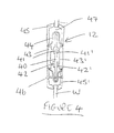
- FIGURE 4 is a sectional view through a remote control device of the assembly of Figure 1.
- Referring to Figure 1 of the drawings, there is shown
an electrical switching apparatus comprising a
control unit 10 for mounting above the ceiling, adjacent an existing lighting fixture for an electrical light 11 and aremote control device 12. -
- Prior to installing the apparatus, the light 11 used to be connected, such that one of its
wires 13 was connected to the neutral wires N, N' of amains supply cables 14,15 of the lighting circuit. - The
other wire 16 of the light 11 was connected directly to a switched output wire from a single wall switch or to switchedoutput wire 17 from a plurality of interconnectedwall switches supply cables 14,15 were connected to awire 20, which feeds live mains to the wall switch or switches. - Thus, it will be appreciated that the light 11 would be energised, whenever the switched
wire 17 from the wall switch or switches became live. - In accordance with this invention, the switching apparatus can be fitted in order to provide one or more extra switch points to supplement or replace any of the existing wall switches that control the light 11.
- The
control unit 10 of the present invention comprises a switched terminal 21 and asensing 22 terminal, as well as conventional live and neutral terminal blocks 23,24. The circuit connected substantially as the existing circuit, with the exception that thelive wire 16 to the light 11 is connected to the switchedterminal 21 of thecontrol unit 10, instead of to the switchedwire 17 from the wall switch or switches. - The switched
wire 17 is connected to thesensing terminal 22 of thecontrol unit 10. Thecontrol unit 10 comprises acontrol circuit 25 incorporating a triac switching device (not shown), which is arranged to apply live mains from the live terminal block 23 to the switchedoutput terminal 21. The gate of the triac is connected to a sensing circuit (not shown) of thecontrol circuit 25. Thecontrol circuit 25 further comprises a radio receiver (not shown), which is arranged to receive radio remote control signals directly from theremote control device 12 or from a repeater device, which extends the range of theremote control device 12. - The
remote control device 12 comprises ON and OFF actuators, which cause the transmitter to respectively transmit control signals for turning the light 11 on and off. - Referring to Figure 2 of the drawings, when power is first applied to the control device 10 a test is performed at
step 30, in order to see whether the triac is configured to apply power to the light 11. If power is applied to the light 11, the triac is controlled to remove power fromterminal 21, so that the light 11 is always off when power is initially applied to thedevice 10. - When the light 11 is off, at
step 31, the sensing circuit of thecontrol circuit 25 continuously monitors whether the receiver has received a remote control ON signal or whether the signal on sensingterminal 22 has changed from 'mains' to 'no mains' or vice-versa. If either of these conditions are detected, the triac is controlled to apply power to the light 11, so that the light 11 is turned on. However, if a remote control OFF signal is received atstep 31, then the light remains off. - When the light 11 is on, at
step 32, the sensing circuit of thecontrol circuit 25 continuously monitors whether the receiver has received a remote control OFF signal or whether the signal on sensingterminal 22 has changed from 'mains' to 'no mains' or vice-versa. If either of these conditions are detected, the triac is controlled to turn the light 11 off, otherwise the light remains on. - It will be appreciated that the signal on the switched
wire 17 from theswitches remote control device 12. - In an alternative embodiment, the control unit can be configured to turn the light on and off whenever appropriate short duration control signals are received. However, if a long duration control signal is received, this has the effect of slowly dimming the light 11 from on to off or vice-versa.
- The
remote control device 12 may be a hand-held device or a wall-mounted device. In the latter case, it will be appreciated that the apparatus has the effect of providing an extra wall switch without the requirement to route wires down the wall from the light 11. - Referring to Figure 3 of the drawings, the control unit will preferably only respond to specified transmitters and the transmitters are arranged to transmit a unique address code within their control signal, so that they can be differentiated. In use, before the control unit is installed, its memory thus has to be programmed with the identities of the transmitters which it is to respond to. This is achieved, at
step 50, by actuating a switch on the control unit to set it in a LEARN mode. In the LEARN mode, the control unit will store the unique address code of any transmitters that are actuated to transmit their control signal within a predetermined time period n. The control unit then reverts automatically into its OPERATE mode. - When the receiver of the control unit receives a control signal, at
step 51, this is decoded to check whether the address code corresponds with an address code programmed into the control unit's memory. Atstep 52, the control unit will then only act on control signals that are received from a transmitter whose address code corresponds with an address code programmed into its memory. - Once the control unit has been installed in a ceiling void, it is no longer possible to gain access to the control unit to put it back into the LEARN mode, say when further transmitters are to be added to the system. Thus, each transmitter may be arranged to transmit a control signal to remotely put the control unit into the LEARN mode.
- When removing transmitters from the system, it is often desirable to initially clear all address codes from the control unit's memory before the same or new address codes are programmed into the control unit's memory. However, this would mean that the control unit would no longer be able to respond to control signals to put it into the LEARN mode and thus the control unit would be rendered useless.
- In order to overcome this problem, each transmitter may be arranged to transmit a control signal to remotely put the control unit into an ERASE mode. In the ERASE mode, the control unit erases all address codes from its memory, with the exception of the address code of the transmitter which gave the command to the control unit to enter the ERASE mode.
- The transmitter which gave the command to the control unit to enter the ERASE mode can then be used to set the control unit in the LEARN mode, whereupon the same or new address codes can be programmed into the control unit's memory, as hereinbefore described.
- Referring to Figure 4 of the drawings, in one embodiment, the
remote device 12 forms a wall switch which can be actuated from either side of a wall W. Thedevice 12 comprises a double-sided printedcircuit board 40 having a pair of ON switches 41,41' and a pair of OFF switches 42,42' arranged on its respective opposite sides. The switches of the same type are electrically connected in parallel with each other. - A battery-powered radio transmitter is also mounted on the printed
circuit board 40. The transmitter is arranged to transmit remote control ON and OFF signals, when therespective switch - The printed
circuit board 44 is enclosed inside aplastics housing 44. A pair of rockingactuators 42,42' are pivotally mounted to thehousing 44 on respective opposite sides of the printedcircuit board 40, such that the ON switches 41,41' are respectively actuated when the top of therespective actuator 43,43' is depressed and such that the OFF switches 42,42' are respectively actuated when the bottom of therespective actuator 43,43' is depressed. - In use, the
remote device 12 is mounted in anaperture 47 in the wall W, where it is retained by apertured face plates 45,45' that are fitted to respective opposite sides of the wall W. The face plates 45,45' are connected to each other by means ofscrews 46. - It will be appreciated that the
remote control device 12 of Figure 3 resembles a conventional wall switch, when viewed from either side of the wall W. However, the device provides the advantage that the light can be controlled from either side of the wall, without the need to run wires to the light 11.
Claims (14)
- An electrical switching apparatus comprising a remote control device which can be actuated to transmit a wireless control signal and a control unit having a receiver for receiving said signal, a switching device for connecting in series between a load to be switched and a current supply, a switch terminal for connecting to a conductor extending from a remote switch, and control means for changing the switching state of said switching device, either when a change is detected in a signal on said switch terminal or when said wireless control signal is received by said receiver.
- An electrical switching apparatus as claimed in claim 1, in which the remote control device comprises a hand-held device.
- An electrical switching apparatus as claimed in claim 1, in which the remote control device comprises means for mounting it to a wall or other surface.
- An electrical switching apparatus as claimed in claim 3, in which the remote control device resembles a conventional wall switch.
- An electrical switching apparatus as claimed in any preceding claim, in which the remote control device is arranged to transmit wireless on and off control signals upon actuation of respective switches, the control device of the control unit being arranged to change the state of said switching device in accordance with the received wireless control signal
- An electrical switching apparatus as claimed in any of claims 1 to 4, in which the remote control device is arranged to transmit a wireless control signal after actuation of a switch, the control device of the control unit being arranged to change the state of said switching device when said wireless control signal is received.
- An electrical switching apparatus as claimed in any preceding claim, in which the control unit comprises a housing for attaching to a ceiling in place of a conventional ceiling lighting rose.
- An electrical switching apparatus as claimed in any preceding claim, in which the switching device can be controlled to vary the amount of power delivered to the load.
- An electrical switching apparatus as claimed in any preceding claim, in which the remote control device is arranged to transmit a unique wireless control signal, the control unit being programmable to respond to selected control devices only.
- A control system comprising a control unit configured to respond to a plurality of remote control devices, wherein at least one of the remote control devices can remotely re-configure the control device to respond solely to it.
- A switch assembly comprising a switching means connected to a transmitting device, said transmitting device being arranged to transmit wireless remote control signals upon actuation of said switching means, the switching means being actuable from either opposite side of the assembly.
- A switch assembly as claimed in claim 11, in which the switching means comprises a pair of switching members electrically connected in parallel to said transmitting device, the switching members each having actuators respectively arranged on opposite sides of the assembly.
- A switch assembly as claimed in claim 11, in which the assembly comprises a single switching member having a pair of actuators respectively arranged on opposite sides of the assembly.
- A switch assembly as claimed in any of claims 11 to 13, comprising a pair of flat face-plates for respectively mounting on opposite sides of the assembly.
Applications Claiming Priority (5)
| Application Number | Priority Date | Filing Date | Title |
|---|---|---|---|
| GB9806771 | 1998-03-31 | ||
| GBGB9806771.3A GB9806771D0 (en) | 1998-03-31 | 1998-03-31 | Electrical switching apparatus |
| GB9825805A GB2336045B (en) | 1998-03-31 | 1998-11-26 | Electrical switching apparatus |
| GB9825805 | 1998-11-26 | ||
| US09/676,221 US6650029B1 (en) | 1998-03-31 | 2000-09-29 | Remotely controllable electrical switching apparatus |
Publications (2)
| Publication Number | Publication Date |
|---|---|
| EP0948114A2 true EP0948114A2 (en) | 1999-10-06 |
| EP0948114A3 EP0948114A3 (en) | 2005-11-30 |
Family
ID=31998592
Family Applications (1)
| Application Number | Title | Priority Date | Filing Date |
|---|---|---|---|
| EP99302452A Withdrawn EP0948114A3 (en) | 1998-03-31 | 1999-03-29 | Electrical switching apparatus |
Country Status (3)
| Country | Link |
|---|---|
| US (1) | US6650029B1 (en) |
| EP (1) | EP0948114A3 (en) |
| GB (1) | GB2375241B (en) |
Cited By (1)
| Publication number | Priority date | Publication date | Assignee | Title |
|---|---|---|---|---|
| WO2017021799A1 (en) * | 2015-08-04 | 2017-02-09 | Khera Balbir Singh | Alternative means for actuation of electric loads connected to conventional switches |
Families Citing this family (26)
| Publication number | Priority date | Publication date | Assignee | Title |
|---|---|---|---|---|
| US7749089B1 (en) | 1999-02-26 | 2010-07-06 | Creative Kingdoms, Llc | Multi-media interactive play system |
| US6761637B2 (en) | 2000-02-22 | 2004-07-13 | Creative Kingdoms, Llc | Method of game play using RFID tracking device |
| US7445550B2 (en) | 2000-02-22 | 2008-11-04 | Creative Kingdoms, Llc | Magical wand and interactive play experience |
| US7878905B2 (en) | 2000-02-22 | 2011-02-01 | Creative Kingdoms, Llc | Multi-layered interactive play experience |
| DE10016712C5 (en) * | 2000-04-04 | 2004-09-16 | Pilz Gmbh & Co. | Safety switching device and method for setting an operating mode of a safety switching device |
| US7066781B2 (en) | 2000-10-20 | 2006-06-27 | Denise Chapman Weston | Children's toy with wireless tag/transponder |
| US20070066396A1 (en) | 2002-04-05 | 2007-03-22 | Denise Chapman Weston | Retail methods for providing an interactive product to a consumer |
| US6967566B2 (en) | 2002-04-05 | 2005-11-22 | Creative Kingdoms, Llc | Live-action interactive adventure game |
| GB2390204B (en) * | 2002-05-29 | 2005-08-31 | Exodus Electronic Ltd | Control systems |
| US7674184B2 (en) | 2002-08-01 | 2010-03-09 | Creative Kingdoms, Llc | Interactive water attraction and quest game |
| US9446319B2 (en) | 2003-03-25 | 2016-09-20 | Mq Gaming, Llc | Interactive gaming toy |
| US8313379B2 (en) | 2005-08-22 | 2012-11-20 | Nintendo Co., Ltd. | Video game system with wireless modular handheld controller |
| JP4805633B2 (en) | 2005-08-22 | 2011-11-02 | 任天堂株式会社 | Game operation device |
| US7927216B2 (en) | 2005-09-15 | 2011-04-19 | Nintendo Co., Ltd. | Video game system with wireless modular handheld controller |
| JP4262726B2 (en) | 2005-08-24 | 2009-05-13 | 任天堂株式会社 | Game controller and game system |
| US8870655B2 (en) | 2005-08-24 | 2014-10-28 | Nintendo Co., Ltd. | Wireless game controllers |
| US8308563B2 (en) | 2005-08-30 | 2012-11-13 | Nintendo Co., Ltd. | Game system and storage medium having game program stored thereon |
| US8157651B2 (en) | 2005-09-12 | 2012-04-17 | Nintendo Co., Ltd. | Information processing program |
| US7698448B2 (en) | 2005-11-04 | 2010-04-13 | Intermatic Incorporated | Proxy commands and devices for a home automation data transfer system |
| US7694005B2 (en) | 2005-11-04 | 2010-04-06 | Intermatic Incorporated | Remote device management in a home automation data transfer system |
| US7870232B2 (en) | 2005-11-04 | 2011-01-11 | Intermatic Incorporated | Messaging in a home automation data transfer system |
| JP4151982B2 (en) | 2006-03-10 | 2008-09-17 | 任天堂株式会社 | Motion discrimination device and motion discrimination program |
| JP5127242B2 (en) | 2007-01-19 | 2013-01-23 | 任天堂株式会社 | Acceleration data processing program and game program |
| US20100070100A1 (en) * | 2008-09-15 | 2010-03-18 | Finlinson Jan F | Control architecture and system for wireless sensing |
| US8508148B1 (en) | 2009-02-01 | 2013-08-13 | MagicLux, LLC | System for light and appliance remote control |
| US20110316453A1 (en) * | 2010-06-29 | 2011-12-29 | Ewing David B | Lighting control systems and methods |
Citations (3)
| Publication number | Priority date | Publication date | Assignee | Title |
|---|---|---|---|---|
| WO1992001968A1 (en) * | 1990-07-23 | 1992-02-06 | Alexander Leon | Multi-mode remote control system |
| US5237264A (en) * | 1987-07-30 | 1993-08-17 | Lutron Electronics Co., Inc. | Remotely controllable power control system |
| US5340954A (en) * | 1991-05-02 | 1994-08-23 | Heath Company | Wireless multiple position switching system |
Family Cites Families (17)
| Publication number | Priority date | Publication date | Assignee | Title |
|---|---|---|---|---|
| GB2051440A (en) * | 1979-06-14 | 1981-01-14 | Duckworth G H | Remote light switch |
| GB2099607A (en) | 1981-05-01 | 1982-12-08 | Thorn Emi Gas Appliances | Heating apparatus control system |
| US5099193A (en) | 1987-07-30 | 1992-03-24 | Lutron Electronics Co., Inc. | Remotely controllable power control system |
| EP0306598A3 (en) * | 1987-09-08 | 1989-08-23 | Clifford Electronics, Inc. | Electronically programmable remote control access systems |
| GB2218552A (en) * | 1988-04-09 | 1989-11-15 | Lawrence Vivian Penheiro | Electric light installation |
| US5189412A (en) * | 1990-05-11 | 1993-02-23 | Hunter Fan Company | Remote control for a ceiling fan |
| US5392454A (en) * | 1992-10-23 | 1995-02-21 | Moog Inc. | Method and apparatus for selectively enabling bi-directional communication only between a dedicated pair of transceivers |
| GB2294569A (en) * | 1994-10-17 | 1996-05-01 | Flecon Multi System Pte Ltd | Wireless control systems |
| US5559406A (en) | 1994-11-18 | 1996-09-24 | Chang; Chin-Hsiung | Ceiling fan and light assembly control circuit with remote controller/single-throw switch optional controls |
| CA2141064A1 (en) * | 1995-06-05 | 1996-12-06 | Luan C. Quach | Remote switched outlet with learning capability |
| US5767841A (en) * | 1995-11-03 | 1998-06-16 | Hartman; William M. | Two-sided trackball |
| AU7621396A (en) | 1995-11-23 | 1997-06-11 | Anne Kristine Henckel | Remote control transmitter and case for the same |
| US5969637A (en) | 1996-04-24 | 1999-10-19 | The Chamberlain Group, Inc. | Garage door opener with light control |
| GB2320119B (en) * | 1996-12-06 | 2000-08-09 | Ronald Mark Henderson | Control device |
| USD406847S (en) * | 1997-03-25 | 1999-03-16 | Corporate Media Partners | Two sided remote control |
| IT1297272B1 (en) * | 1997-07-03 | 1999-08-09 | Ferport S A S Di M Biassoni E | REMOTE CONTROL SYSTEM WITH CODE PROGRAMMING |
| US5895985A (en) * | 1997-11-19 | 1999-04-20 | Fischer; George | Switch remoting system |
-
1998
- 1998-11-26 GB GB0217218A patent/GB2375241B/en not_active Expired - Fee Related
-
1999
- 1999-03-29 EP EP99302452A patent/EP0948114A3/en not_active Withdrawn
-
2000
- 2000-09-29 US US09/676,221 patent/US6650029B1/en not_active Expired - Fee Related
Patent Citations (3)
| Publication number | Priority date | Publication date | Assignee | Title |
|---|---|---|---|---|
| US5237264A (en) * | 1987-07-30 | 1993-08-17 | Lutron Electronics Co., Inc. | Remotely controllable power control system |
| WO1992001968A1 (en) * | 1990-07-23 | 1992-02-06 | Alexander Leon | Multi-mode remote control system |
| US5340954A (en) * | 1991-05-02 | 1994-08-23 | Heath Company | Wireless multiple position switching system |
Cited By (1)
| Publication number | Priority date | Publication date | Assignee | Title |
|---|---|---|---|---|
| WO2017021799A1 (en) * | 2015-08-04 | 2017-02-09 | Khera Balbir Singh | Alternative means for actuation of electric loads connected to conventional switches |
Also Published As
| Publication number | Publication date |
|---|---|
| GB0217218D0 (en) | 2002-09-04 |
| GB2375241A (en) | 2002-11-06 |
| EP0948114A3 (en) | 2005-11-30 |
| GB2375241B (en) | 2003-03-19 |
| US6650029B1 (en) | 2003-11-18 |
Similar Documents
| Publication | Publication Date | Title |
|---|---|---|
| US6650029B1 (en) | Remotely controllable electrical switching apparatus | |
| EP2754165B1 (en) | Method and apparatus for switching on-off a group or all lights or appliances of premises | |
| US7671544B2 (en) | System and architecture for controlling lighting through a low-voltage bus | |
| AU2012243250B2 (en) | Method and apparatus for combining AC power relay and current sensors with AC wiring devices | |
| EP0872162B1 (en) | Lighting control | |
| WO2002035653A3 (en) | Distributed lighting control system | |
| US5867017A (en) | Energy control system with remote switching | |
| GB2336045A (en) | Remotely controllable electrical switching apparatus | |
| US20100039240A1 (en) | Method for Wiring Devices in a Structure Using a Wireless Network | |
| CN116439551A (en) | Mirror with human body induction wireless switch for adjusting light and color and bathroom mirror cabinet | |
| JPH10304467A (en) | Terminal equipment for load control and load control system | |
| EP0923060A2 (en) | Wireless remote control system for electrical devices | |
| JP6798570B2 (en) | Light source unit | |
| GB2365231A (en) | Method and apparatus for the control of lighting circuits | |
| GB2414100A (en) | A configurable marshalling box | |
| KR100604988B1 (en) | A switching device for remote control | |
| KR200263214Y1 (en) | Guidance broadcast system for using speaker | |
| JP3112281B2 (en) | Selector switch terminal | |
| KR200300082Y1 (en) | indoor use small switch with a bilateral power line communication circuit driven by an one-chip microprocessor | |
| CZ772U1 (en) | Remote control system | |
| AU2022244101A1 (en) | Method for configuring a luminaire system and device for use therein | |
| JPH0361399B2 (en) | ||
| EP1366645A1 (en) | Lighting unit | |
| KR20050037705A (en) | Method for connecting electric wiring | |
| JPH04154081A (en) | Illumination remote control system |
Legal Events
| Date | Code | Title | Description |
|---|---|---|---|
| PUAI | Public reference made under article 153(3) epc to a published international application that has entered the european phase |
Free format text: ORIGINAL CODE: 0009012 |
|
| AK | Designated contracting states |
Kind code of ref document: A2 Designated state(s): AT BE CH CY DE DK ES FI FR GB GR IE IT LI LU MC NL PT SE |
|
| AX | Request for extension of the european patent |
Free format text: AL;LT;LV;MK;RO;SI |
|
| RAP1 | Party data changed (applicant data changed or rights of an application transferred) |
Owner name: FITZGERALD LIGHTING LTD |
|
| PUAL | Search report despatched |
Free format text: ORIGINAL CODE: 0009013 |
|
| AK | Designated contracting states |
Kind code of ref document: A3 Designated state(s): AT BE CH CY DE DK ES FI FR GB GR IE IT LI LU MC NL PT SE |
|
| AX | Request for extension of the european patent |
Extension state: AL LT LV MK RO SI |
|
| AKX | Designation fees paid | ||
| REG | Reference to a national code |
Ref country code: DE Ref legal event code: 8566 |
|
| STAA | Information on the status of an ep patent application or granted ep patent |
Free format text: STATUS: THE APPLICATION IS DEEMED TO BE WITHDRAWN |
|
| 18D | Application deemed to be withdrawn |
Effective date: 20060830 |