EP0945926A2 - Armor stop for metal clad cable connector - Google Patents
Armor stop for metal clad cable connector Download PDFInfo
- Publication number
- EP0945926A2 EP0945926A2 EP99302349A EP99302349A EP0945926A2 EP 0945926 A2 EP0945926 A2 EP 0945926A2 EP 99302349 A EP99302349 A EP 99302349A EP 99302349 A EP99302349 A EP 99302349A EP 0945926 A2 EP0945926 A2 EP 0945926A2
- Authority
- EP
- European Patent Office
- Prior art keywords
- armor stop
- cable
- armor
- passageway
- connector
- Prior art date
- Legal status (The legal status is an assumption and is not a legal conclusion. Google has not performed a legal analysis and makes no representation as to the accuracy of the status listed.)
- Granted
Links
- 239000002184 metal Substances 0.000 title claims description 24
- 239000004020 conductor Substances 0.000 claims abstract description 56
- 238000005253 cladding Methods 0.000 claims description 19
- 238000003780 insertion Methods 0.000 claims description 4
- 230000037431 insertion Effects 0.000 claims description 4
- 238000007789 sealing Methods 0.000 description 15
- 210000004907 gland Anatomy 0.000 description 5
- 238000004382 potting Methods 0.000 description 4
- 150000001875 compounds Chemical class 0.000 description 3
- 239000004677 Nylon Substances 0.000 description 1
- 239000004743 Polypropylene Substances 0.000 description 1
- 230000004308 accommodation Effects 0.000 description 1
- 230000002411 adverse Effects 0.000 description 1
- 230000015572 biosynthetic process Effects 0.000 description 1
- 230000007613 environmental effect Effects 0.000 description 1
- 230000009969 flowable effect Effects 0.000 description 1
- 231100001261 hazardous Toxicity 0.000 description 1
- 238000009434 installation Methods 0.000 description 1
- 238000009413 insulation Methods 0.000 description 1
- 239000000463 material Substances 0.000 description 1
- 229920001778 nylon Polymers 0.000 description 1
- 239000004033 plastic Substances 0.000 description 1
- -1 polypropylene Polymers 0.000 description 1
- 229920001155 polypropylene Polymers 0.000 description 1
- 238000009877 rendering Methods 0.000 description 1
- 239000011800 void material Substances 0.000 description 1
Images


Classifications
-
- H—ELECTRICITY
- H01—ELECTRIC ELEMENTS
- H01R—ELECTRICALLY-CONDUCTIVE CONNECTIONS; STRUCTURAL ASSOCIATIONS OF A PLURALITY OF MUTUALLY-INSULATED ELECTRICAL CONNECTING ELEMENTS; COUPLING DEVICES; CURRENT COLLECTORS
- H01R9/00—Structural associations of a plurality of mutually-insulated electrical connecting elements, e.g. terminal strips or terminal blocks; Terminals or binding posts mounted upon a base or in a case; Bases therefor
- H01R9/03—Connectors arranged to contact a plurality of the conductors of a multiconductor cable, e.g. tapping connections
- H01R9/05—Connectors arranged to contact a plurality of the conductors of a multiconductor cable, e.g. tapping connections for coaxial cables
- H01R9/0524—Connection to outer conductor by action of a clamping member, e.g. screw fastening means
-
- H—ELECTRICITY
- H01—ELECTRIC ELEMENTS
- H01R—ELECTRICALLY-CONDUCTIVE CONNECTIONS; STRUCTURAL ASSOCIATIONS OF A PLURALITY OF MUTUALLY-INSULATED ELECTRICAL CONNECTING ELEMENTS; COUPLING DEVICES; CURRENT COLLECTORS
- H01R13/00—Details of coupling devices of the kinds covered by groups H01R12/70 or H01R24/00 - H01R33/00
- H01R13/46—Bases; Cases
- H01R13/52—Dustproof, splashproof, drip-proof, waterproof, or flameproof cases
- H01R13/5205—Sealing means between cable and housing, e.g. grommet
Definitions
- the present invention relates to the field of electrical connectors. More specifically, the present invention is directed to a removable armor stop for a range taking electrical connector for a metal clad cable.
- Electrical connectors have long been used to terminate and connect a variety of cables which carry electrical power or signals.
- Electrical cables such as those carrying power, are supplied in various configurations based upon a particular application or the location in which the cables are to be used.
- One type of electrical cable includes plural insulated conductors extending within an outer insulated jacket. Such cables may also include an inner metallic sheath or cladding between the outer jacket and the conductors.
- Connectors of the type used to terminate such cables must provide for field engagement between the outer jacket of the cable and the connector. These connectors must also provide for grounded electrical engagement between the cladding of the cable and the body of the connector.
- Connectors of this type may be designed to uniquely terminate one size of electrical cable or to terminate a range of sizes of electrical cables. These connectors typically include intricate components which must be employed to effectively seal the cable and the connector while also adequately establishing ground connection between the cladding of cable and the connector body. Consequently, these connectors must be able to precisely locate the cable within the connector to assure proper ground termination.
- the range taking feature of this connector is enhanced by the provision of a removable armor stop which inserts into one end of the connector body.
- the armor stop desirably takes the form of an elongate cylindrical wall having a given thickness and is threadingly received within a cable egress end of the connector body.
- the armor stop When inserted into the connector, the armor stop provides one transverse edge in substantially coplanar alignment with an annular internal shoulder of the connector. The annular edge of the metal cladding normally abuts against the internal shoulder of the connector when fully inserted therein.
- the thickness of the insertable armor stop at its transverse edge allows the connector to accommodate an even greater range of diameters of metal cladding of the cable which the connector may then accommodate.
- the armor stop further provides a positive position stop for ensuring correct positioning of the metal cladding within the connector so as to provide secure mechanical and electrical connection of the cable.
- the art has also seen other designs for armor stops which increase the range taking ability of a connector such as, for example, a washer type component employed against the internal shoulder and allowing the conductors of the cable to pass through a central aperture that is smaller than that defined by the internal shoulder.
- the conductors of the cable extend from the cladding adjacent the internal shoulder through an open sealing chamber which defines the exit end of the connector.
- the armor stops being about the conductors of the cable, are similarly positioned within this sealing chamber. For some applications in hazardous locations it is desirable to fill the vacant portion of the sealing chamber with a sealing or potting compound so as to seal the connector and prevent the formation of a flame path therethrough.
- the installer When using a cylindrical armor stop of the above-mentioned copending application, the installer must therefore cut the armor stop in order to remove it from about the conductors of the cable. Cutting through the armor stop poses a risk of the installer also cutting through an inner insulation covering or an internal conductor of the cable and adversely affecting the performance of the cable. Additionally, in order to remove a washer type armor stop of the prior art, it is necessary to disassemble the connector after the cable has been fixed with respect to one component of the connector. The disassembly operation can be time consuming and, in some workspaces or environmental conditions, difficult to perform. Such disassembly operations also present a risk of the connector being improperly re-assembled.
- the present invention provides a removable armor stop for a range taking electrical connector for a metal clad cable which provides a positive stop for cable being inserted into the connector so as to ensure correct and secure mechanical and electrical connection between the cable and the connector.
- the present invention further provides a removable armor stop for a range taking electrical connector which may be manually removed by an installer without requiring additional tools.
- the present invention still further provides a removable armor stop for a range taking electrical connector which reliably seats various sizes of metal clad cable within the electrical connector and which is removably insertably engagable with the electrical connector and removably receivable of the conductors of the metal clad cable through an elongate opening formed therein.
- the armor stop of the present invention is removably insertable into a range taking electrical connector used for terminating a first-sized multiconductor cable having a metal cladding of a diameter within a first range of diameters.
- the connector includes a connector housing defining a cable ingress opening, a conductor egress opening, and an elongate cable passageway extending therebetween.
- the connector further includes an internal annular shoulder extending into the cable passageway and providing for abutting engagement with the metal cladding of a first-sized cable.
- the removable armor stop is insertable into the conductor egress opening for providing abutting engagement with metal cladding of a second-sized multiconductor cable having a diameter smaller than the first-sized cable.
- the removable armor stop includes an elongate arcuate armor stop wall having opposed inner and outer surfaces.
- the inner surface defines a conductor receiving passageway for receiving one or more conductors of the second-sized cable.
- the armor stop wall includes a first end insertable into the connector passageway and has a thickness, defined between the inner and outer surfaces, which prevents the metal cladding of the second-sized cable from being inserted into the conductor receiving passageway.
- the armor stop wall is circumferentially discontinuous about the one or more conductors received in the conductor receiving passageway so as to allow the one or more conductors received therein to pass therethrough.
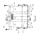
- Figure 1 shows a cross sectional view of a removable armor stop of the present invention and an associated range taking electrical connector.
- Figure 2 shows a cross sectional view of the removable armor stop of the present invention positioned within the range taking electrical connector of Figure 1.
- Figure 3a shows a side elevational view of a removable armor stop of the present invention in an open, uninserted configuration.
- Figure 3b shows a top elevational view of a the removable armor stop of Figure 3a.
- Figure 3c shows a cross-sectional view of the removable armor stop of Figure 3a taken through the line A-A.
- Figure 3d shows a cross-sectional view of the removable armor stop of Figure 3a taken through the line B-B.
- Figure 3e shows a cross-sectional view of the removable armor stop of Figure 3a taken through the line D-D.
- Figure 3f shows a cross-sectional partial view of the removable armor stop of Figure 3a.
- Figure 3g shows a cross-sectional view of the removable armor stop of Figure 3a taken through the line C-C.
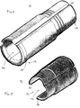
- Figure 4 shows an isometric view of a removable armor stop of the present invention in the closed configuration for insertion into a range taking electrical connector.
- Figure 5 shows the removable armor stop of Figure 4 in the open configuration for receivably engaging or removably disengaging the conductors of a metal clad cable.
- a removable armor stop 10 of the present invention is shown positioned adjacent to a range taking electrical connector 12. While connector 12 is shown and herein described as having similar components as provided in the commonly assigned and copending U.S. Patent Application Serial No. 08/939,258, incorporated by reference herein, it is contemplated that armor stop 10 may be employed with any range taking electrical connector which may accommodate armor stop 10.
- Connector 12 provides for mechanical and electrical securement of an elongate metal clad cable 14.
- Metal clad cable 14 includes an outer insulative jacket 16 surrounding a scroll type metallic cladding or sheath 18.
- Sheath 18 longitudinally encloses a number of conductors 19 extending through cable 14. These electrical conductors are contemplated as including individually insulated jackets themselves or may simply be uncoated. A portion of jacket 16 at one end of cable 14 may be stripped from its surrounding contact over sheath 18. Sheath 18 may then be cut to provide an annular edge 18a for abutting contact with an internal shoulder 20 of connector 12. Internal shoulder 20 defines an aperture 22 through which the plurality of electrical conductors 19 comprising the contents of cable sheath 18 may pass through so as to exit connector 12 through a cable egress opening 24.
- Connector 12 provides an elongate sealing cavity 26 defined by an internal gland wall 28 and an internal sealing sleeve wall 29. Sealing cavity 26 extends from an area adjacent annular edge 18a to cable egress opening 24.
- Internal shoulder 20 may abuttingly accommodate sheaths of a range of diameters but is generally limited to sheaths having an external diameter greater than the diameter of aperture 22.
- Armor stop 10 is formed to be removably insertable within sealing cavity 26 by threading engagement with threads formed on internal gland wall 28.
- Armor stop 10 is desirably formed of a suitable plastic material such as nylon, polypropylene, or the like.
- armor stop 10 is an elongate generally cylindrical member having a cylindrical wall 30, opposed first and second ends 30a and 30b, and a central bore 30c therethrough.
- End 30b includes an annularly enlarged collar 30d thereat.
- End 30b of armor stop 10 is externally screw threaded for screw accommodation with internal gland wall 28 as shown in Figures 1 and 4.
- the upper surface of collar 30d may include a slotted location 30e for accommodating a tool to permit screw insertion of armor stop 10 into cable egress opening 24 of connector 12.
- Elongate channel 32 may be formed as a substantially straight gap between opposing wall edges 34 and 36 as shown in Figures 3a-g and 5. Edges 34 and 36 are desirably formed to deflect if so required to allow conductors 19 to pass through channel 32 into or out of central bore 30c.
- wall 30 may include at least one elongate hinge 40 formed by the closed end of a notch opening towards major surface 31a. Opposing wall edges 34 and 36 are thereby formed on opposing sides, so as to more easily deflect about, of the at least one elongate hinge 40.
- Hinge 40 allows an installer to readily reconfigure armor stop 10 between an open position, shown in Figure 5, so as to allow conductors 19 to pass through channel 32, and a closed position, shown in Figure 4, so as to allow armor stop 10 to achieve a cylindrical configuration and to receive conductors 19 within central bore 30c. Furthermore, in the closed position, armor stop may be removably inserted in the sealing cavity 26 of connector 12. The readiness of the present invention to be opened or closed about conductors 19 of cable 14 provides for easier assembly and potting of a range taking electrical connector.
- Figures 3a-g provides details of another armor stop 110 of the present invention.
- Figures 3a and 3b show armor stop 110 in a fully open configuration in which a central bore 110c is accessible to the conductors 19 of cable 14.
- Armor stop 110 includes three elongate arcuate walls 112, 114, and 116 which define central bore 110c.
- Armor stop 110 desirably provides three longitudinally successive and distinct exterior diameters when in the closed configuration.
- the first distinct exterior diameter is provided by wall portions 112a, 114a, and 116a.
- Wall portion 114a may further include one or more elongate threads 115 so as to provide threading engagement between armor stop 110 and internal gland wall 28 of connector 12.
- the second distinct exterior diameter is provided by wall portions 112b, 114b, and 116b.
- the third distinct exterior diameter is provided by wall portions 112c, 114c, and 116c which define an annularly large collar providing an annular stop surface 134 which limits the insertion of armor stop 110 into connector
- Wall 114 connects to wall 112 across a first proximal hinge 118a and a first distal hinge 120a. Wall 114 similarly connects to wall 116 across a second proximal hinge 118b and a second distal hinge 120b.
- Armor stop 110 defines a first elongate window 122 between first hinges 118a and 120a and a second elongate window 124 between second hinges 118b and 120b.
- Wall 112 includes an elongate edge 126 and wall 116 includes an opposed elongate edge 128. Edges 126 and 128 define an elongate channel 132 therebetween through which conductors 19 of cable 14 are received and delivered from central bore 110c. The span of channel 132 between edges 126 and 128 changes as armor stop 110 is reconfigured between an closed configuration to an open configuration.
- armor stop 10 simply entails inserting the armor stop into sealing chamber 26 so that edge 31 is substantially co-planar with internal shoulder 20 so as to increase the range of sizes of cables connector 12 may accommodate. At least a portion of sheath edge 18a abuts armor stop edge 31 so as to properly position cable 14 within connector 12.
- armor stop 10 may be backed out of sealing connector 12 by rotating collar 30d about central bore 30c.
- armor stop 10 may be manually removed from about conductors 19 extending by passing conductors 19 through channel 32.
- conductors 19 of cable 14 may then be potted within sealing cavity 26 using a flowable sealing compound which may fill the void remaining between conductors 19 and internal gland wall 28.
- channel 32 may take other forms as well.
- channel 32 may be formed between overlapping deflectable edges 34 and 36 (not shown).
- channel 32 may be formed as a helical channel formed between opposed deflectable edges 34 and 36 (not shown) and may further include a frangible connecting seam (not shown) which may be opened by transversely pulling one end of edge 34 with respect to the opposed end of edge 36.
- the present invention provides an armor stop with a generally cylindrical configuration where an opening or passage may be established in the wall thereof to permit removal of the stop from its position about an extending electrical conductor without requiring cutting or the use of tools.
Abstract
Description
- The present invention relates to the field of electrical connectors. More specifically, the present invention is directed to a removable armor stop for a range taking electrical connector for a metal clad cable.
- Electrical connectors have long been used to terminate and connect a variety of cables which carry electrical power or signals. Electrical cables, such as those carrying power, are supplied in various configurations based upon a particular application or the location in which the cables are to be used. One type of electrical cable includes plural insulated conductors extending within an outer insulated jacket. Such cables may also include an inner metallic sheath or cladding between the outer jacket and the conductors. Connectors of the type used to terminate such cables must provide for field engagement between the outer jacket of the cable and the connector. These connectors must also provide for grounded electrical engagement between the cladding of the cable and the body of the connector.
- Connectors of this type may be designed to uniquely terminate one size of electrical cable or to terminate a range of sizes of electrical cables. These connectors typically include intricate components which must be employed to effectively seal the cable and the connector while also adequately establishing ground connection between the cladding of cable and the connector body. Consequently, these connectors must be able to precisely locate the cable within the connector to assure proper ground termination.
- It is generally difficult to properly locate cables of different sizes in a single connector. One such connector which may be used to terminate a metal clad electrical cable is shown and described in commonly signed U.S. Patent No. 5,059,747 and which is incorporated by reference herein for all purposes. The connector described in the '747 patent provides for field termination of the metal clad electrical cable by effectively establishing a seal between the connector body and the jacket of the cable. This connector also establishes ground connection between the connector body and the metallic jacket of the cable. The connector of the '747 patent provides the ability to accommodate cables of different diameters by providing a grounding element which accommodates metal cladding of different diameters. Thus the connector of the '747 patent provides a range taking feature with respect to the metal cladding of the cable.
- Another example of a range taking electrical connector is provided in the commonly assigned and copending U.S. Patent Application Serial No. 08/939,258 and which is incorporated by reference herein for all purposes. The range taking feature of this connector is enhanced by the provision of a removable armor stop which inserts into one end of the connector body. The armor stop desirably takes the form of an elongate cylindrical wall having a given thickness and is threadingly received within a cable egress end of the connector body. When inserted into the connector, the armor stop provides one transverse edge in substantially coplanar alignment with an annular internal shoulder of the connector. The annular edge of the metal cladding normally abuts against the internal shoulder of the connector when fully inserted therein. The thickness of the insertable armor stop at its transverse edge allows the connector to accommodate an even greater range of diameters of metal cladding of the cable which the connector may then accommodate. The armor stop further provides a positive position stop for ensuring correct positioning of the metal cladding within the connector so as to provide secure mechanical and electrical connection of the cable. The art has also seen other designs for armor stops which increase the range taking ability of a connector such as, for example, a washer type component employed against the internal shoulder and allowing the conductors of the cable to pass through a central aperture that is smaller than that defined by the internal shoulder.
- Once the metal clad cable is properly positioned within the connector, the conductors of the cable extend from the cladding adjacent the internal shoulder through an open sealing chamber which defines the exit end of the connector. The armor stops, being about the conductors of the cable, are similarly positioned within this sealing chamber. For some applications in hazardous locations it is desirable to fill the vacant portion of the sealing chamber with a sealing or potting compound so as to seal the connector and prevent the formation of a flame path therethrough.
- It is generally desirable to remove the armor stop from the connector so that the sealing compound may more fully flow into, and more fully occupy, the sealing chamber. The circumstances surrounding the installation, however, may complicate removal of the armor stop. For instance, it is common for an installer to insert the free ends of the conductors through a panel or wall prior to potting, rendering the free ends of the conductor inaccessible for the simple sliding of the armor stop thereover. Additionally, many installers prefer to terminate the free ends of the conductors prior to potting the conductors within the connector. Furthermore, the length of an exposed conductor extending from a connector can be quite long so that it is inconvenient for the installer to attempt to slide the armor stop off the free ends thereof.
- When using a cylindrical armor stop of the above-mentioned copending application, the installer must therefore cut the armor stop in order to remove it from about the conductors of the cable. Cutting through the armor stop poses a risk of the installer also cutting through an inner insulation covering or an internal conductor of the cable and adversely affecting the performance of the cable. Additionally, in order to remove a washer type armor stop of the prior art, it is necessary to disassemble the connector after the cable has been fixed with respect to one component of the connector. The disassembly operation can be time consuming and, in some workspaces or environmental conditions, difficult to perform. Such disassembly operations also present a risk of the connector being improperly re-assembled.
- The present invention provides a removable armor stop for a range taking electrical connector for a metal clad cable which provides a positive stop for cable being inserted into the connector so as to ensure correct and secure mechanical and electrical connection between the cable and the connector.
- The present invention further provides a removable armor stop for a range taking electrical connector which may be manually removed by an installer without requiring additional tools.
- The present invention still further provides a removable armor stop for a range taking electrical connector which reliably seats various sizes of metal clad cable within the electrical connector and which is removably insertably engagable with the electrical connector and removably receivable of the conductors of the metal clad cable through an elongate opening formed therein.
- The armor stop of the present invention is removably insertable into a range taking electrical connector used for terminating a first-sized multiconductor cable having a metal cladding of a diameter within a first range of diameters. The connector includes a connector housing defining a cable ingress opening, a conductor egress opening, and an elongate cable passageway extending therebetween. The connector further includes an internal annular shoulder extending into the cable passageway and providing for abutting engagement with the metal cladding of a first-sized cable. The removable armor stop is insertable into the conductor egress opening for providing abutting engagement with metal cladding of a second-sized multiconductor cable having a diameter smaller than the first-sized cable. The removable armor stop includes an elongate arcuate armor stop wall having opposed inner and outer surfaces. The inner surface defines a conductor receiving passageway for receiving one or more conductors of the second-sized cable. The armor stop wall includes a first end insertable into the connector passageway and has a thickness, defined between the inner and outer surfaces, which prevents the metal cladding of the second-sized cable from being inserted into the conductor receiving passageway. The armor stop wall is circumferentially discontinuous about the one or more conductors received in the conductor receiving passageway so as to allow the one or more conductors received therein to pass therethrough.
- The present invention will be more readily appreciated in a reading of the "Detailed Description of the Invention" with reference to the following drawings.
- Figure 1 shows a cross sectional view of a removable armor stop of the present invention and an associated range taking electrical connector.
- Figure 2 shows a cross sectional view of the removable armor stop of the present invention positioned within the range taking electrical connector of Figure 1.
- Figure 3a shows a side elevational view of a removable armor stop of the present invention in an open, uninserted configuration.
- Figure 3b shows a top elevational view of a the removable armor stop of Figure 3a.
- Figure 3c shows a cross-sectional view of the removable armor stop of Figure 3a taken through the line A-A.
- Figure 3d shows a cross-sectional view of the removable armor stop of Figure 3a taken through the line B-B.
- Figure 3e shows a cross-sectional view of the removable armor stop of Figure 3a taken through the line D-D.
- Figure 3f shows a cross-sectional partial view of the removable armor stop of Figure 3a.
- Figure 3g shows a cross-sectional view of the removable armor stop of Figure 3a taken through the line C-C.
- Figure 4 shows an isometric view of a removable armor stop of the present invention in the closed configuration for insertion into a range taking electrical connector.
- Figure 5 shows the removable armor stop of Figure 4 in the open configuration for receivably engaging or removably disengaging the conductors of a metal clad cable.
- Referring to Figure 1, a
removable armor stop 10 of the present invention is shown positioned adjacent to a range takingelectrical connector 12. Whileconnector 12 is shown and herein described as having similar components as provided in the commonly assigned and copending U.S. Patent Application Serial No. 08/939,258, incorporated by reference herein, it is contemplated thatarmor stop 10 may be employed with any range taking electrical connector which may accommodatearmor stop 10.Connector 12 provides for mechanical and electrical securement of an elongate metal cladcable 14. - Metal clad
cable 14 includes anouter insulative jacket 16 surrounding a scroll type metallic cladding orsheath 18.Sheath 18 longitudinally encloses a number ofconductors 19 extending throughcable 14. These electrical conductors are contemplated as including individually insulated jackets themselves or may simply be uncoated. A portion ofjacket 16 at one end ofcable 14 may be stripped from its surrounding contact oversheath 18.Sheath 18 may then be cut to provide an annular edge 18a for abutting contact with aninternal shoulder 20 ofconnector 12.Internal shoulder 20 defines anaperture 22 through which the plurality ofelectrical conductors 19 comprising the contents ofcable sheath 18 may pass through so as to exitconnector 12 through acable egress opening 24.Connector 12 provides an elongate sealingcavity 26 defined by an internal gland wall 28 and an internal sealing sleeve wall 29. Sealingcavity 26 extends from an area adjacent annular edge 18a tocable egress opening 24. -
Internal shoulder 20 may abuttingly accommodate sheaths of a range of diameters but is generally limited to sheaths having an external diameter greater than the diameter ofaperture 22.Armor stop 10 is formed to be removably insertable within sealingcavity 26 by threading engagement with threads formed on internal gland wall 28. -
Armor stop 10 is desirably formed of a suitable plastic material such as nylon, polypropylene, or the like. As shown particularly in Figures 1, 3a-g, and 4,armor stop 10 is an elongate generally cylindrical member having acylindrical wall 30, opposed first and second ends 30a and 30b, and a central bore 30c therethrough. End 30b includes an annularlyenlarged collar 30d thereat. End 30b ofarmor stop 10 is externally screw threaded for screw accommodation with internal gland wall 28 as shown in Figures 1 and 4. The upper surface ofcollar 30d may include a slotted location 30e for accommodating a tool to permit screw insertion ofarmor stop 10 intocable egress opening 24 ofconnector 12. - The present invention contemplates that armor stop 10
permits cable conductors 19 to pass through anelongate channel 32 formed bywall 30.Elongate channel 32 may be formed as a substantially straight gap between opposing wall edges 34 and 36 as shown in Figures 3a-g and 5.Edges conductors 19 to pass throughchannel 32 into or out of central bore 30c. As seen in Figure 5,wall 30 may include at least oneelongate hinge 40 formed by the closed end of a notch opening towards major surface 31a. Opposing wall edges 34 and 36 are thereby formed on opposing sides, so as to more easily deflect about, of the at least oneelongate hinge 40.Hinge 40 allows an installer to readily reconfigure armor stop 10 between an open position, shown in Figure 5, so as to allowconductors 19 to pass throughchannel 32, and a closed position, shown in Figure 4, so as to allow armor stop 10 to achieve a cylindrical configuration and to receiveconductors 19 within central bore 30c. Furthermore, in the closed position, armor stop may be removably inserted in the sealingcavity 26 ofconnector 12. The readiness of the present invention to be opened or closed aboutconductors 19 ofcable 14 provides for easier assembly and potting of a range taking electrical connector. - Figures 3a-g provides details of another
armor stop 110 of the present invention. Figures 3a and 3b showarmor stop 110 in a fully open configuration in which a central bore 110c is accessible to theconductors 19 ofcable 14.Armor stop 110 includes three elongatearcuate walls Armor stop 110 desirably provides three longitudinally successive and distinct exterior diameters when in the closed configuration. The first distinct exterior diameter is provided bywall portions 112a, 114a, and 116a. Wall portion 114a may further include one or moreelongate threads 115 so as to provide threading engagement betweenarmor stop 110 and internal gland wall 28 ofconnector 12. The second distinct exterior diameter is provided bywall portions 112b, 114b, and 116b. The third distinct exterior diameter is provided bywall portions 112c, 114c, and 116c which define an annularly large collar providing anannular stop surface 134 which limits the insertion ofarmor stop 110 intoconnector 12 so thatcable 14 may be properly positioned therein. -
Wall 114 connects to wall 112 across a first proximal hinge 118a and a firstdistal hinge 120a.Wall 114 similarly connects to wall 116 across a second proximal hinge 118b and a seconddistal hinge 120b.Armor stop 110 defines a firstelongate window 122 betweenfirst hinges 118a and 120a and a secondelongate window 124 betweensecond hinges 118b and 120b.Wall 112 includes anelongate edge 126 andwall 116 includes an opposedelongate edge 128.Edges elongate channel 132 therebetween through whichconductors 19 ofcable 14 are received and delivered from central bore 110c. The span ofchannel 132 betweenedges armor stop 110 is reconfigured between an closed configuration to an open configuration. - Operation of
armor stop 10 simply entails inserting the armor stop into sealingchamber 26 so that edge 31 is substantially co-planar withinternal shoulder 20 so as to increase the range of sizes ofcables connector 12 may accommodate. At least a portion of sheath edge 18a abuts armor stop edge 31 so as to properly positioncable 14 withinconnector 12. Once the connector components are fully assembled,armor stop 10 may be backed out of sealingconnector 12 by rotatingcollar 30d about central bore 30c. When the free ends of theconductors 19 are terminated in electrical connection,armor stop 10 may be manually removed from aboutconductors 19 extending by passingconductors 19 throughchannel 32.conductors 19 ofcable 14 may then be potted within sealingcavity 26 using a flowable sealing compound which may fill the void remaining betweenconductors 19 and internal gland wall 28. - It is also contemplated that
channel 32 may take other forms as well. For example,channel 32 may be formed between overlappingdeflectable edges 34 and 36 (not shown). Similarly,channel 32 may be formed as a helical channel formed between opposeddeflectable edges 34 and 36 (not shown) and may further include a frangible connecting seam (not shown) which may be opened by transversely pulling one end ofedge 34 with respect to the opposed end ofedge 36. - Thus the present invention provides an armor stop with a generally cylindrical configuration where an opening or passage may be established in the wall thereof to permit removal of the stop from its position about an extending electrical conductor without requiring cutting or the use of tools.
- Various changes to the foregoing described and shown structures would now be evident to those skilled in the art. Accordingly, the particularly disclosed scope of the invention is set forth in the following claims.
Claims (10)
- A removable armor stop for a range taking electrical connector for terminating a first-sized multiconductor cable having a metal cladding of a diameter within a first range of diameters, said connector including a connector housing defining a cable ingress opening, a conductor egress opening, and an elongate cable passageway extending therebetween, said connector further including an internal annular shoulder extending into said cable passageway and providing for abutting engagement with the metal cladding of the first-sized cable, which removable armor stop is insertable into the conductor egress opening for providing abutting engagement with metal cladding of a second-sized multiconductor cable having a diameter smaller than the first-sized cable, said removable armor stop comprising:an elongate arcuate armor stop wall having opposed inner and outer surfaces, said inner surface defining a conductor receiving passageway for receiving one or more conductors of the second-sized cable;said armor stop wall including a first end insertable into said connector passageway and having a thickness defined between said inner and outer surfaces which prevents the metal cladding of the second-sized cable from being inserted into said conductor receiving passageway; andsaid armor stop wall being circumferentially discontinuous about the one or more conductors received in said conductor receiving passageway so as to allow the one or more conductors received therein to pass therethrough.
- The removable armor stop of claim 1, wherein said outer surface of said armor stop wall engages an interior surface of the range taking electrical connector about cable passageway.
- The removable armor stop of claim 1 or claim 2, wherein said outer surface of said armor stop wall is screw threaded.
- The removable armor stop of any one of claims 1 to 3, further including an annularly-enlarged collar to limit insertion of said first end of said armor stop into said terminating passageway.
- The removable armor stop of any one of claims 1 to 4, wherein said armor stop wall further includes at least one notch having a closed end defining a flexible hinge about which said armor stop wall deflects between an open configuration allowing the one or more conductors received in said conductor receiving passageway to be removed through said armor stop wall and a closed configuration allowing said armor stop to be inserted into the range taking electrical connector.
- The removable armor stop of claim 5, wherein said armor stop wall defines at least one elongate longitudinal window bounded by flexible hinges about which said armor stop wall deflects between an open configuration allowing said one or more conductors received in said conductor receiving passageway to be removed through said armor stop wall and a closed configuration allowing said armor stop to be inserted into the range taking electrical connector.
- The removable armor stop of any one of claims 1 to 6, wherein said armor stop wall further includes opposed longitudinal edges extending in overlapping registry with each other so as to be deflectable to allow said cable in said cable passageway to pass therethrough.
- The removable armor stop of any one of claims 1 to 7, wherein said armor stop wall defines an elongate gap between opposed longitudinal edges thereof through which the one or more conductors in said conductor receiving passageway may pass.
- The removable armor stop of claim 8, wherein said armor stop wall defines an elongate helical gap between opposed longitudinal edges thereof.
- The removable armor stop of any one of claims 1 to 9, wherein said armor stop wall includes a first end positionable adjacent to the interior shoulder of the electrical connector for abutting engagement with the cladding of the second-sized cable.
Applications Claiming Priority (2)
| Application Number | Priority Date | Filing Date | Title |
|---|---|---|---|
| US7974498P | 1998-03-27 | 1998-03-27 | |
| US79744P | 1998-03-27 |
Publications (3)
| Publication Number | Publication Date |
|---|---|
| EP0945926A2 true EP0945926A2 (en) | 1999-09-29 |
| EP0945926A3 EP0945926A3 (en) | 2000-03-08 |
| EP0945926B1 EP0945926B1 (en) | 2004-12-01 |
Family
ID=22152526
Family Applications (1)
| Application Number | Title | Priority Date | Filing Date |
|---|---|---|---|
| EP99302349A Expired - Lifetime EP0945926B1 (en) | 1998-03-27 | 1999-03-26 | Armor stop for metal clad cable connector |
Country Status (7)
| Country | Link |
|---|---|
| US (1) | US6299485B1 (en) |
| EP (1) | EP0945926B1 (en) |
| JP (1) | JPH11341663A (en) |
| CN (1) | CN1134864C (en) |
| CA (1) | CA2266935C (en) |
| DE (1) | DE69922285T2 (en) |
| ES (1) | ES2234208T3 (en) |
Families Citing this family (8)
| Publication number | Priority date | Publication date | Assignee | Title |
|---|---|---|---|---|
| US7128619B1 (en) | 2004-11-05 | 2006-10-31 | Mcgraw-Edison Company | Connector system and method for securing a cable in a connector system |
| ES2360389T3 (en) * | 2007-07-10 | 2011-06-03 | Clipper Windpower, Inc. | SAFETY PLUG TO SEAL THE EXTREME CONNECTIONS OF A COLLECTOR BAR. |
| CN101599626B (en) * | 2008-06-04 | 2012-08-29 | 东亚贝斯特株式会社 | Cable joint for connecting a sheathed cable with sheathed part and fixation method of sheathed part |
| US20110053421A1 (en) * | 2009-08-31 | 2011-03-03 | Mostoller Matthew Edward | Electrical connector for terminating the end of an electrical cable |
| JP5638932B2 (en) * | 2010-12-21 | 2014-12-10 | 矢崎総業株式会社 | Electronic component built-in connector |
| USD771569S1 (en) | 2016-02-12 | 2016-11-15 | Bridgeport Fittings, Inc. | Electrical connector with cable armor stop |
| USD815604S1 (en) | 2016-02-12 | 2018-04-17 | Bridgeport Fittings, Inc. | Cable armor stop |
| US10367344B2 (en) | 2016-03-02 | 2019-07-30 | Bridgeport Fittings, Incorporated | Cable armor stop |
Citations (5)
| Publication number | Priority date | Publication date | Assignee | Title |
|---|---|---|---|---|
| US3671926A (en) * | 1970-08-03 | 1972-06-20 | Lindsay Specialty Prod Ltd | Coaxial cable connector |
| FR2655122A1 (en) * | 1989-11-30 | 1991-05-31 | Souriau & Cie | Seal for an electrical connector, and connector which is equipped therewith |
| EP0542102A1 (en) * | 1991-11-13 | 1993-05-19 | Contact GmbH Elektrische Bauelemente | Electrical connector for shielded cables |
| US5352134A (en) * | 1993-06-21 | 1994-10-04 | Cabel-Con, Inc. | RF shielded coaxial cable connector |
| US5458507A (en) * | 1993-09-10 | 1995-10-17 | Eft Interests, Ltd. | Fluid resistant electrical connector with boot-type seal assembly |
Family Cites Families (4)
| Publication number | Priority date | Publication date | Assignee | Title |
|---|---|---|---|---|
| US4963104A (en) * | 1989-05-01 | 1990-10-16 | Spark Innovations, Inc. | Shielded connector assembly |
| DE19529692A1 (en) * | 1995-08-11 | 1997-02-13 | Gore W L & Ass Gmbh | End housing for a connector |
| JPH1022001A (en) * | 1996-07-04 | 1998-01-23 | Sumitomo Wiring Syst Ltd | Processing structure for shielding layer of shielding wire |
| US5951327A (en) * | 1997-09-29 | 1999-09-14 | Thomas & Betts International, Inc. | Connector for use with multiple sizes of cables |
-
1999
- 1999-03-23 US US09/274,986 patent/US6299485B1/en not_active Expired - Lifetime
- 1999-03-25 CA CA002266935A patent/CA2266935C/en not_active Expired - Lifetime
- 1999-03-26 EP EP99302349A patent/EP0945926B1/en not_active Expired - Lifetime
- 1999-03-26 ES ES99302349T patent/ES2234208T3/en not_active Expired - Lifetime
- 1999-03-26 JP JP11083977A patent/JPH11341663A/en active Pending
- 1999-03-26 DE DE69922285T patent/DE69922285T2/en not_active Expired - Lifetime
- 1999-03-29 CN CNB991047435A patent/CN1134864C/en not_active Expired - Lifetime
Patent Citations (5)
| Publication number | Priority date | Publication date | Assignee | Title |
|---|---|---|---|---|
| US3671926A (en) * | 1970-08-03 | 1972-06-20 | Lindsay Specialty Prod Ltd | Coaxial cable connector |
| FR2655122A1 (en) * | 1989-11-30 | 1991-05-31 | Souriau & Cie | Seal for an electrical connector, and connector which is equipped therewith |
| EP0542102A1 (en) * | 1991-11-13 | 1993-05-19 | Contact GmbH Elektrische Bauelemente | Electrical connector for shielded cables |
| US5352134A (en) * | 1993-06-21 | 1994-10-04 | Cabel-Con, Inc. | RF shielded coaxial cable connector |
| US5458507A (en) * | 1993-09-10 | 1995-10-17 | Eft Interests, Ltd. | Fluid resistant electrical connector with boot-type seal assembly |
Also Published As
| Publication number | Publication date |
|---|---|
| CA2266935C (en) | 2007-03-20 |
| JPH11341663A (en) | 1999-12-10 |
| DE69922285D1 (en) | 2005-01-05 |
| CA2266935A1 (en) | 1999-09-27 |
| US6299485B1 (en) | 2001-10-09 |
| CN1134864C (en) | 2004-01-14 |
| ES2234208T3 (en) | 2005-06-16 |
| EP0945926A3 (en) | 2000-03-08 |
| DE69922285T2 (en) | 2005-12-22 |
| CN1230804A (en) | 1999-10-06 |
| EP0945926B1 (en) | 2004-12-01 |
Similar Documents
| Publication | Publication Date | Title |
|---|---|---|
| KR101327578B1 (en) | Connection article for a cable, holder for a connector of such a connection article, and kit for connecting cables | |
| KR100880051B1 (en) | Prepless coaxial cable connector | |
| US7568943B2 (en) | Sealing and retaining cable attachment for telecommunications closures | |
| US6817910B2 (en) | Thermoplastic molded set screw connector assembly | |
| EP3410543B1 (en) | Splice connector assemblies | |
| US6168455B1 (en) | Coaxial cable connector | |
| US20060042814A1 (en) | Sealing member for enclosures | |
| KR101765344B1 (en) | Cold-shrink separable connector | |
| CA2266935C (en) | Armor stop for metal clad cable connector | |
| US6007384A (en) | Casing for a plug for a cable having a drain wire | |
| AU2005305032B2 (en) | Electrical connector | |
| WO2010084343A2 (en) | Improvements in and relating to electrical connector housings | |
| US20020176674A1 (en) | Fiber optic cable shield bond system | |
| MXPA99002937A (en) | Armor stop for cable connector armored from me | |
| US20100178785A1 (en) | Wire connection unit | |
| EP3355426A1 (en) | Tubular insulating seal and corresponding insulating arrangement | |
| WO2021118813A1 (en) | Coaxial cable connector termination and splice unit requiring no cable preparation | |
| AU728278B2 (en) | Telephone test set line cord strain relief attachment assembly | |
| DE4338681A1 (en) | Cable plug for electrical connections | |
| CA1148880A (en) | Cable seal splice enclosure | |
| EP0129353A2 (en) | A cable gland | |
| US20060032047A1 (en) | Connector filler element insertion tool and method | |
| EP0782222A1 (en) | Electrical connector | |
| JPH09153382A (en) | Wiring connector for automatic transmission |
Legal Events
| Date | Code | Title | Description |
|---|---|---|---|
| PUAI | Public reference made under article 153(3) epc to a published international application that has entered the european phase |
Free format text: ORIGINAL CODE: 0009012 |
|
| AK | Designated contracting states |
Kind code of ref document: A2 Designated state(s): BE CH DE ES FR GB IT LI LU NL SE |
|
| AX | Request for extension of the european patent |
Free format text: AL;LT;LV;MK;RO;SI |
|
| PUAL | Search report despatched |
Free format text: ORIGINAL CODE: 0009013 |
|
| AK | Designated contracting states |
Kind code of ref document: A3 Designated state(s): AT BE CH CY DE DK ES FI FR GB GR IE IT LI LU MC NL PT SE |
|
| AX | Request for extension of the european patent |
Free format text: AL;LT;LV;MK;RO;SI |
|
| 17P | Request for examination filed |
Effective date: 20000516 |
|
| AKX | Designation fees paid |
Free format text: BE CH DE ES FR GB IT LI LU NL SE |
|
| RAP1 | Party data changed (applicant data changed or rights of an application transferred) |
Owner name: THOMAS & BETTS INTERNATIONAL, INC. |
|
| 17Q | First examination report despatched |
Effective date: 20030123 |
|
| GRAP | Despatch of communication of intention to grant a patent |
Free format text: ORIGINAL CODE: EPIDOSNIGR1 |
|
| GRAS | Grant fee paid |
Free format text: ORIGINAL CODE: EPIDOSNIGR3 |
|
| GRAA | (expected) grant |
Free format text: ORIGINAL CODE: 0009210 |
|
| AK | Designated contracting states |
Kind code of ref document: B1 Designated state(s): BE CH DE ES FR GB IT LI LU NL SE |
|
| REG | Reference to a national code |
Ref country code: GB Ref legal event code: FG4D |
|
| REG | Reference to a national code |
Ref country code: CH Ref legal event code: EP |
|
| REF | Corresponds to: |
Ref document number: 69922285 Country of ref document: DE Date of ref document: 20050105 Kind code of ref document: P |
|
| REG | Reference to a national code |
Ref country code: CH Ref legal event code: NV Representative=s name: BOVARD AG PATENTANWAELTE |
|
| REG | Reference to a national code |
Ref country code: SE Ref legal event code: TRGR |
|
| REG | Reference to a national code |
Ref country code: ES Ref legal event code: FG2A Ref document number: 2234208 Country of ref document: ES Kind code of ref document: T3 |
|
| ET | Fr: translation filed | ||
| PLBE | No opposition filed within time limit |
Free format text: ORIGINAL CODE: 0009261 |
|
| STAA | Information on the status of an ep patent application or granted ep patent |
Free format text: STATUS: NO OPPOSITION FILED WITHIN TIME LIMIT |
|
| 26N | No opposition filed |
Effective date: 20050902 |
|
| REG | Reference to a national code |
Ref country code: CH Ref legal event code: PFA Owner name: THOMAS & BETTS INTERNATIONAL, INC. Free format text: THOMAS & BETTS INTERNATIONAL, INC.#250 LILLARD DRIVE#SPARKS, NEVADA 89434 (US) -TRANSFER TO- THOMAS & BETTS INTERNATIONAL, INC.#250 LILLARD DRIVE#SPARKS, NEVADA 89434 (US) |
|
| REG | Reference to a national code |
Ref country code: FR Ref legal event code: PLFP Year of fee payment: 18 |
|
| REG | Reference to a national code |
Ref country code: FR Ref legal event code: PLFP Year of fee payment: 19 |
|
| REG | Reference to a national code |
Ref country code: FR Ref legal event code: PLFP Year of fee payment: 20 |
|
| PGFP | Annual fee paid to national office [announced via postgrant information from national office to epo] |
Ref country code: BE Payment date: 20171227 Year of fee payment: 20 |
|
| PGFP | Annual fee paid to national office [announced via postgrant information from national office to epo] |
Ref country code: GB Payment date: 20180321 Year of fee payment: 20 Ref country code: LU Payment date: 20180308 Year of fee payment: 20 Ref country code: DE Payment date: 20180313 Year of fee payment: 20 Ref country code: CH Payment date: 20180314 Year of fee payment: 20 Ref country code: NL Payment date: 20180314 Year of fee payment: 20 |
|
| PGFP | Annual fee paid to national office [announced via postgrant information from national office to epo] |
Ref country code: FR Payment date: 20180223 Year of fee payment: 20 Ref country code: IT Payment date: 20180321 Year of fee payment: 20 Ref country code: SE Payment date: 20180313 Year of fee payment: 20 |
|
| PGFP | Annual fee paid to national office [announced via postgrant information from national office to epo] |
Ref country code: ES Payment date: 20180402 Year of fee payment: 20 |
|
| REG | Reference to a national code |
Ref country code: DE Ref legal event code: R071 Ref document number: 69922285 Country of ref document: DE |
|
| REG | Reference to a national code |
Ref country code: NL Ref legal event code: MK Effective date: 20190325 |
|
| REG | Reference to a national code |
Ref country code: CH Ref legal event code: PL |
|
| REG | Reference to a national code |
Ref country code: GB Ref legal event code: PE20 Expiry date: 20190325 |
|
| PG25 | Lapsed in a contracting state [announced via postgrant information from national office to epo] |
Ref country code: GB Free format text: LAPSE BECAUSE OF EXPIRATION OF PROTECTION Effective date: 20190325 |
|
| REG | Reference to a national code |
Ref country code: BE Ref legal event code: MK Effective date: 20190326 |
|
| REG | Reference to a national code |
Ref country code: ES Ref legal event code: FD2A Effective date: 20200724 |
|
| PG25 | Lapsed in a contracting state [announced via postgrant information from national office to epo] |
Ref country code: ES Free format text: LAPSE BECAUSE OF EXPIRATION OF PROTECTION Effective date: 20190327 |