EP0945586A2 - Method and apparatus for forming a wellbore junction - Google Patents
Method and apparatus for forming a wellbore junction Download PDFInfo
- Publication number
- EP0945586A2 EP0945586A2 EP99302059A EP99302059A EP0945586A2 EP 0945586 A2 EP0945586 A2 EP 0945586A2 EP 99302059 A EP99302059 A EP 99302059A EP 99302059 A EP99302059 A EP 99302059A EP 0945586 A2 EP0945586 A2 EP 0945586A2
- Authority
- EP
- European Patent Office
- Prior art keywords
- opening
- wellbore
- tubular member
- blocking member
- flange
- Prior art date
- Legal status (The legal status is an assumption and is not a legal conclusion. Google has not performed a legal analysis and makes no representation as to the accuracy of the status listed.)
- Withdrawn
Links
Images


Classifications
-
- E—FIXED CONSTRUCTIONS
- E21—EARTH DRILLING; MINING
- E21B—EARTH DRILLING, e.g. DEEP DRILLING; OBTAINING OIL, GAS, WATER, SOLUBLE OR MELTABLE MATERIALS OR A SLURRY OF MINERALS FROM WELLS
- E21B7/00—Special methods or apparatus for drilling
- E21B7/04—Directional drilling
- E21B7/06—Deflecting the direction of boreholes
- E21B7/061—Deflecting the direction of boreholes the tool shaft advancing relative to a guide, e.g. a curved tube or a whipstock
Definitions
- the present invention relates generally to operations performed in conjunction with subterranean wells and, in an embodiment described herein, more particularly provides apparatus and methods for forming wellbore junctions. More specifically, the invention relates to a lateral wellbore junction having a displaceable casing blocking member.
- Wellbore junctions are formed when a second wellbore is drilled intersecting a first wellbore.
- the first wellbore may be designated a "parent" or “main” wellbore
- the second wellbore may be designated a "lateral” or “branch” wellbore.
- the casing, liners, or other conduits installed at or through the junction to be isolated from fluid communication with the formation surrounding the junction.
- a wellbore junction apparatus which includes a tubular member having an opening formed through a sidewall thereof.
- the opening is selectively blocked by a blocking member.
- the blocking member is shifted downhole to provide access through the opening, thereby permitting cutting tools to be passed through the opening for drilling a lateral wellbore.
- the blocking member is a sleeve externally disposed about a section of casing.
- the sleeve may be shifted relative to the casing by engaging one or more shifting profiles formed internally on the sleeve and accessible via the opening, by applying fluid pressure to a hydraulic actuator attached thereto, etc.
- a conduit may be installed through the opening and inserted into the lateral wellbore.
- a flange may be attached to the conduit. The flange may be sealingly engaged with the tubular member about a periphery of the opening, thereby providing fluid isolation between the tubular member and conduit, and the formation surrounding the wellbore junction.
- the flange may be biased into engagement with the tubular member.
- a biasing force may be applied by an anchoring device attached to the conduit, may be applied by the sleeve, etc.
- the sleeve may have a profile formed thereon which engages a complementarily shaped profile on a portion of the flange extending through the opening. Such engagement may provide the biasing force and/or may secure the flange relative to the tubular member.
- the sleeve may be shielded from contact with a sidewall of the parent wellbore, and/or from contact with cement placed in the parent wellbore, by an enclosure outwardly surrounding the sleeve.
- the enclosure may be an inflatable membrane attached externally to the tubular member. If inflatable, the membrane may be radially outwardly extended in response to fluid pressure within the tubular member.
- decentralizing devices may be attached to the tubular member, in order to provide increased clearance between the opening and the parent wellbore sidewall. The decentralizing devices may also be responsive to fluid pressure within the tubular member.
- a method of forming a wellbore junction comprising the steps of: drilling a first wellbore; providing a tubular member having an opening formed through a sidewall portion thereof, and a blocking member selectively positionable relative to the opening in a first position in which the blocking member blocks the opening and a second position in which the blocking member permits access through the opening; positioning the tubular member within the first wellbore; positioning the blocking member in the second position; and drilling a second wellbore by passing at least one cutting tool through the opening.
- the method further comprises the step of sealingly engaging the blocking member with the tubular member when the blocking member is in the first position, the blocking member thereby preventing fluid flow through the opening.
- the second wellbore drilling step further comprises installing a deflection device assembly including a deflection device within the tubular member, and deflecting the at least one cutting tool off of the deflection device.
- the installing step further may further comprise aligning a laterally inclined face of the deflection device with the opening.
- the installing step may further comprise engaging the deflection device assembly with an orienting profile.
- the method further comprises the step of underreaming a portion of the first wellbore, and wherein the tubular member positioning step further comprises positioning the tubular member within the underreamed portion.
- the method further comprises the step of shifting the blocking member between its first and second positions after the tubular member positioning step.
- the shifting step may be performed by engaging a shifting profile formed on the blocking member or by applying fluid pressure to the tubular member.
- the method further comprises the steps of attaching first and second packers axially straddling the tubular member, sealingly engaging the first and second packers with the first wellbore, and forcing cementitious material into the first wellbore on sides of the first and second packers opposite the opening.
- the method further comprises the step of engaging a flange with the tubular member about a periphery of the opening.
- the flange engaging step may further comprise sealingly engaging the flange with the tubular member.
- a conduit may be attached to the flange, and the conduit may be installed within the second wellbore.
- the conduit installing step may further comprise passing the conduit through the opening.
- the conduit installing step may further comprise biasing the conduit outwardly relative to the opening, thereby biasing the flange against an interior surface of the tubular member.
- the method may further comprise the step of engaging the blocking member with the conduit, thereby securing the conduit relative to the tubular member.
- the blocking member engaging step may further comprise biasing the flange against an interior surface of the tubular member.
- the blocking member engaging step may further comprise engaging a first profile formed on the blocking member with a second profile formed on the conduit.
- the first profile engaging step may further comprise biasing the flange against an interior surface of the tubular member.
- the tubular member further comprises an outwardly extendable membrane surrounding the blocking member.
- the method may further comprise the step of radially outwardly extending the membrane after the tubular member positioning step.
- the extending step may further comprise forcing fluid into the membrane.
- the fluid forcing step may further comprise forcing the fluid through the tubular member.
- the extending step may be performed after a step of depositing cementitious material into an annulus formed between the membrane and the first wellbore.
- the second wellbore drilling step may further comprise drilling through the membrane.
- the method further comprises the step of forcing the tubular member toward a sidewall of the first wellbore, thereby decentralizing the tubular member within the first wellbore.
- the tubular member forcing step may further comprise increasing a clearance between the opening and the first wellbore.
- the tubular member forcing step may further comprise applying fluid pressure to the interior of the tubular member.
- the method may further comprise the step of outwardly extending a membrane surrounding the blocking member, thereby engaging the membrane with the first wellbore.
- a method of forming a wellbore junction comprising the steps of: disposing a blocking member relative to a tubular member having an opening formed through a sidewall thereof, the blocking member being displaceable between a first position in which the blocking member prevents access through the opening, and a second position in which the blocking member permits access through the opening; disposing a shielding device externally relative to the blocking member; positioning the tubular member within a first wellbore; positioning the blocking member in the second position; and passing at least one cutting tool through the opening, thereby drilling through the shielding device and drilling a second wellbore intersecting the first wellbore.
- the method further comprises the step of radially outwardly extending the shielding device into contact with the first wellbore.
- the extending step may be performed by applying fluid pressure to the shielding device.
- the extending step may be performed after forcing cementitious material into an annulus formed between the shielding device and the first wellbore.
- the method further comprises the step of displacing the opening laterally away from a sidewall of the first wellbore before the drilling step.
- the displacing step may be performed by applying fluid pressure to the tubular member.
- the method further comprises the step of engaging a flange with the tubular member about a periphery of the opening.
- the flange engaging step may further comprise sealingly engaging the flange with the tubular member.
- the method may further comprise the steps of attaching a conduit to the flange, and installing the conduit within the second wellbore.
- the conduit installing step may further comprise passing the conduit through the opening.
- the conduit installing step may further comprise biasing the conduit outwardly relative to the opening, thereby biasing the flange against an interior surface of the tubular member.
- the method may further comprise the step of engaging the blocking member with the conduit, thereby securing the conduit relative to the tubular member.
- the blocking member engaging step may further comprise biasing the flange against an interior surface of the tubular member.
- the blocking member engaging step may further comprise engaging a first profile formed on the blocking member with a second profile formed on the conduit.
- the first profile engaging step may further comprise biasing the flange against an interior surface of the tubular member.
- apparatus for forming a wellbore junction comprising: a tubular member having an opening formed through a sidewall portion thereof; a blocking member selectively positionable relative to the opening in a first position in which the blocking member blocks the opening, and a second position in which the blocking member permits access through the opening; and a deflection device assembly including a deflection device having an inclined surface formed thereon, the surface being aligned relative to the opening.
- the deflection device assembly is engaged with an orienting profile attached to the tubular member.
- the blocking member is sealingly engageable with the tubular member in the first position, preventing fluid flow through the opening.
- the blocking member is a sleeve externally disposed and axially reciprocable relative to the tubular member.
- apparatus for forming a wellbore junction comprising: a tubular member having an opening formed through a sidewall thereof; a blocking member displaceable relative to the tubular member and selectively permitting and preventing access through the opening; and a flange sealingly engaged with the tubular member about a periphery of the opening.
- the flange is sealingly engaged with an inner side surface of the tubular member.
- the flange is sealingly attached to a conduit extending outwardly from the tubular member.
- the conduit may be in fluid communication with the interior of the tubular member via the flange.
- the flange is secured relative to the tubular member by engagement between the blocking member and a portion of the flange extending through the opening.
- a first profile formed on the blocking member may be engaged with a second profile formed on the flange portion.
- the blocking member is a sleeve externally disposed and axially reciprocable relative to the tubular member.
- apparatus for forming a wellbore junction comprising: a tubular member having an opening formed through a sidewall thereof; a blocking member displaceable relative to the tubular member and selectively permitting and preventing access through the opening; and an enclosure outwardly disposed relative to the blocking member.
- the enclosure is an outwardly extendable membrane.
- the membrane may have opposite ends, the opposite ends being attached to the tubular member axially straddling the blocking member.
- the enclosure is inflatable.
- the enclosure may be inflatable in response to fluid pressure within the tubular member.
- the apparatus further comprises a decentralizing device attached to the tubular member.
- the decentralizing device may be responsive to fluid pressure within the tubular member.
- FIGS. 1A-1D Representatively and schematically illustrated in FIGS. 1A-1D is a method 10 of forming a wellbore junction which embodies principles of the present invention.
- directional terms such as “above”, “below”, “upper”, “lower”, etc., are used for convenience in referring to the accompanying drawings. Additionally, it is to be understood that the various embodiments of the present invention described herein may be utilized in various orientations, such as inclined, inverted, horizontal, vertical, etc., without departing from the principles of the present invention.
- a first or parent wellbore 12 has been drilled intersecting an earth strata or formation 14.
- the parent wellbore 12 may optionally be underreamed or otherwise radially enlarged, as indicated by the dashed lines 16, but it is to be clearly understood that such underreaming is not necessary in the method 10.
- a casing string 18 is then installed in the parent wellbore 12.
- the casing string 18 may actually be segmented, may include multiple casing sections, may include other tools and/or equipment, may include conventional devices, such as a cementing shoe, float collar, etc.
- the casing string 18 as viewed in FIG. 1A includes spaced apart packers 20, 22 interconnected therein.
- the packers 20, 22 may be inflatable packers of the type well known to those skilled in the art, or may be other types of packers.
- the packers 20, 22 are set in the wellbore 12 prior to a cementing operation, for purposes that will be described more fully below.
- Cement 24 or another cementitious material is flowed into an annulus 26 formed radially between the casing string 18 and the wellbore 12.
- the cement 24 is forced into the annulus 26 above the upper packer 20 and below the lower packer 22. but not between the packers.
- a section 28 of the casing string 18 is disposed axially between the packers 20, 22.
- This section 28 is a part of an overall apparatus 30 embodying principles of the present invention.
- the casing section 28 may be integrally formed with other portions of the casing string 18, or may be separately attached thereto.
- An opening 32 is formed through a sidewall of the casing 28. As shown in FIGS. 1A-1D, the opening is oval-shaped and axially extended relative to the casing 28. However, it is to be clearly understood that the opening 32 may be otherwise-shaped and oriented without departing from the principles of the present invention. For example, the opening 32 could be rectangular or elliptical and could be circumferentially elongated. When installed in the wellbore 12, the opening 32 may be radially oriented relative to the wellbore by using a conventional gyroscope, highside indicator, or other means, so that the opening faces toward a desired point of intersection with a lateral wellbore 60 (see FIG. 1B).
- the apparatus 30 also includes a blocking member or sleeve 34.
- the sleeve 34 as shown in FIGS. 1A-1D is generally tubular, is externally disposed relative to the casing 28, and is axially reciprocable relative to the casing to block or permit access through the opening 32.
- the blocking member 34 it will be readily appreciated that it is not necessary for the blocking member 34 to be tubular, it could be internally disposed in the casing 28, and could be rotationally or otherwise displaceable relative to the casing.
- the sleeve 34 is blocking access through the opening 32.
- Circumferential seals 36 are carried internally on the sleeve 34, so that, in this position, the sleeve sealingly engages the casing 28 above and below the opening 32. Thus, fluid flow is prevented through the opening 32.
- This configuration of the apparatus 30 is advantageous during the cementing operation described above, in order to prevent cement from flowing outward through the opening 32.
- the sleeve 34 includes axially spaced apart shifting profiles 38 formed internally thereon.
- the profiles 38 are accessible via the opening 32 and may be engaged by a shifting tool (not shown) of the type well known to those skilled in the art. As described more fully below, the profiles 38 may be engaged by the shifting tool and a force applied thereto to shift the sleeve 34 relative to the opening 32. Any number of the profiles 38 may be provided. and it is to be clearly understood that the sleeve 34 may be otherwise displaced relative to the casing 28, such as by application of fluid pressure to a hydraulic actuator attached thereto (see FIG. 1D), without departing from the principles of the present invention.
- the apparatus 30 may further include an optional projection or key 40 formed externally on the casing 28.
- the key 40 is received in a axially extending optional recess or keyway 42 formed internally on the sleeve 34. Engagement between the key 40 and keyway 42 maintains alignment between the sleeve 34 and casing 28.
- Other means of maintaining alignment may be utilized, such.as splines, etc., and the means may be otherwise oriented, for example, if the blocking member 34 displaces circumferentially or rotates relative to the opening 32, the alignment means may be circumferentially oriented, etc.
- FIG. 1B it may be seen that the sleeve 34 has been shifted upward relative to the opening 32, so that access is now permitted through the opening. It will now be appreciated that the cement 24 is not placed between the packers 20, 22 as described above, so that the sleeve 34 is free to displace externally on the casing 28. In this view it may also be seen that the sleeve 34 has a profile 44 formed thereon, the profile including an inclined edge 46.
- the apparatus 30 now also includes a deflection device assembly 48, which has been installed in the casing 28, for example, by conveying it downwardly through the casing string 18 from the earth's surface.
- the deflection device assembly 48 includes a deflection device or whipstock 50, and an optional anchoring device or packer 52.
- an upper laterally inclined deflection surface 54 is radially oriented to face toward the opening 32. Such radial orientation may be accomplished by using a gyroscope, highside indicator, etc., according to conventional techniques.
- the deflection device assembly 48 may be engaged with a helical orienting profile 56 of the apparatus 30.
- a projection 58 of the assembly 48 may engage the profile 56 as the assembly is lowered into the casing 28, thereby automatically orienting the surface 54 to face toward the opening 32.
- the packer 52 may then be set in the casing 28 to anchor the assembly 48 therein and to aid in preventing debris from being trapped between the assembly 48 and the casing 28.
- the orienting profile 56 may be used to orient the shifting tool (not shown). so that the shifting tool may properly engage the profiles 38 through the opening 32 for displacing the sleeve 34 as described above.
- the profile 56 is formed at a reduction of the inner diameter of the casing 28, but other alignment profiles are commercially available which do not require a reduced inner diameter, and any of these may be used in place of the profile 56.
- one or more cutting tools such as drill bits, reamers, etc. (not shown), may be lowered through the casing string 18 and deflected laterally by the surface 54 through the opening 32. In this manner, a second or lateral wellbore 60 may be drilled intersecting the parent wellbore 12.
- the method 10 permits drilling the lateral wellbore 60 through the casing string 18, without the need to mill through the casing 28, and without the need to form the casing out of a relatively weak, brittle, and/or expensive drillable material, such as fiber-reinforced resin, plastic, or aluminum, etc.
- FIG. 1C it may be seen that the deflection device assembly 48 has been retrieved from within the apparatus 30.
- a flange 62 and attached conduit or liner 64 have been installed in the apparatus 30, so that the liner extends outwardly from the opening 32.
- the flange 62 and conduit 64 are shown as separate elements in FIG. 1C, however, it is to be clearly understood that they may be integrally formed, or may be made up of multiple elements, without departing from the principles of the present invention.
- the flange 62 and conduit 64 may also be conveyed into the casing string 18 attached as shown in FIG. 1 C, or may be separately conveyed.
- the flange 62 may be installed in the casing 28 initially and the conduit 64 later attached to the flange. This could be accomplished by providing a conventional polished bore receptacle (not shown) on the flange 62 and sealingly engaging the conduit 64 with the receptacle.
- the flange 62 is shown in FIG. 1C as being made of metal, but it is to be clearly understood that the flange may be made of other materials.
- the flange could be made of an elastomeric material so that it could be "folded” or otherwise deformed if need be, until it is appropriately positioned within the apparatus 30. Such "folding" or other deforming of the flange 62 could also be accomplished if the flange were made of a deformable steel or other material.
- a portion 66 extends outwardly through the opening 32.
- the portion may be a portion of the flange 62 as shown in FIG. 1C, a portion of the conduit 64, or a separately formed portion of the apparatus 30.
- the profile 44 of the sleeve 34 is complementarily shaped relative to the exterior of the portion 66, for purposes that will be more fully described below.
- the flange 62 is positioned so that it contacts the interior of the casing 28 sidewall about a periphery of the opening 32. Sealing engagement may be provided by a seal 68 carried on the flange 62. Alternatively, the flange 62 may be adhesively bonded to the periphery of the opening 32, otherwise engaged with the opening, etc.
- the sealing engagement between the flange 62 and the casing 28 as shown in FIG. 1 C provides fluid isolation between the interior of the casing and the annulus 26, and between the liner 64 and the annulus.
- flange 62 could additionally or alternatively sealingly engage the interior of the sleeve 34, for example, by appropriately positioning the seal 68 between the flange and the sleeve, adding another sealing device for this purpose, etc.
- the flange 62 may be biased into contact with the casing 28.
- an anchoring device or packer 70 attached to the liner 64 may be utilized to exert a downwardly biasing force on the liner, thereby biasing the flange 62 against the interior surface of the casing 28 and maintaining sealing engagement therebetween.
- Other methods of biasing the flange 62 are described below.
- FIG. 1D it may be seen that the sleeve 34 has been downwardly shifted relative to the casing 28, as compared to that shown in FIG. 1 C.
- the inclined edge 46 of the profile 44 on the sleeve 34 is now engaged with the portion 66.
- Such engagement secures the flange 62 relative to the casing 28, preventing relative movement therebetween, and may also bias the flange 62 into contact with the casing 28.
- This biasing is due to engagement between the inclined edge 46 and a complementarily shaped recess 72 formed on the portion 66.
- the edge 46 and recess 72 may be otherwise shaped without departing from the principles of the present invention.
- FIG. 1 D also shows an alternative configuration of the opening 32, in which a lower portion of the opening engages the flange 62, thereby supporting the flange and further restricting lateral movement of the flange relative to the casing 28.
- the lower portion of the opening 32 is shown in FIG. 1D as being generally tapered or wedge-shaped and complementarily engaging the portion 66, it is to be understood that other shapes and types of engagements may be utilized, without departing from the principles of the present invention.
- FIG. 1 D shows an optional projection 78 formed externally on the liner 64 opposite the casing 28 from the flange 62.
- the projection 78 operates to enhance the structural integrity of the flange-to-casing engagement by further restricting lateral displacement of the flange 62 relative to the casing 28, and by supporting the periphery of the opening 32.
- Additional projections 78 may be provided or may be continuously formed about the area where the portion 66 extends through the lower portion of the opening 32.
- the projection 78 is shown as having a generally semi-circular cross-section, but other shapes could be utilized, and the projection could be complementarily shaped relative to the exterior of the casing 28, in keeping with the principles of the present invention.
- FIG. 2 an enlarged cross-sectional view is shown of the interconnection between the sleeve 34, flange 62, portion 66, and casing 28.
- the profile 44 engages the recess 72 to either side of the portion 66, and that this engagement applies an outwardly biasing force to the flange 62.
- This biasing force may be utilized to compress the seal 68 (shown in FIG. 2 in an optional form) between the flange 62 and the inner side surface of the casing 28.
- an optional hydraulic actuator 76 is shown attached to the apparatus 30.
- the hydraulic actuator 76 is formed by differential piston areas on the casing 28 and sleeve 34, so that fluid pressure applied within the casing will cause the sleeve to be biased downwardly.
- fluid pressure could be otherwise applied, such as via a control line extending to another part of the well, additional differential piston areas could be provided to bias the sleeve upwardly, and other types of hydraulic actuators could be provided, without departing from the principles of the present invention.
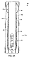
- FIGS. 3A & 3B another method 80 of forming a wellbore junction is schematically and representatively illustrated. Elements which are similar to those previously described are indicated in FIGS. 3A & 3B using the same reference numbers, with an added suffix "a".
- the casing string 18a includes one or more centralizers 82 and an apparatus 84 for forming the wellbore junction.
- the apparatus 84 includes a section of casing 86, a sleeve 88 and a shielding device or enclosure 90 outwardly surrounding the sleeve.
- the sleeve 88 may be shaped differently from that shown, may be displaceable relative to the casing 86 in any of a variety of manners, may be internally or externally disposed relative to the casing, may be sealingly engaged with the casing, may have an actuator attached thereto, may include other profiles formed thereon, etc.
- the sleeve 88 is in a position in which it blocks access through the opening 32a.
- the enclosure 90 may be a membrane, may be made of an elastomeric material, may be similar in many respects to an inflatable packer element, and is radially outwardly extendable relative to the casing 86.
- the enclosure 90 prevents the sleeve 88 from contacting cement 24a flowed into the annulus 26a, and provides radial clearance about the apparatus 84.
- the enclosure 90 is externally and sealingly attached at its opposite ends to the casing 86 above and below the sleeve 88.
- a port 92 provides fluid communication between the interior of the enclosure 90 and the interior of the casing 86.
- the enclosure 90 could be otherwise attached, made of different materials, such as metal, mechanically or otherwise extendable instead of inflatable. etc.. without departing from the principles of the present invention.
- the apparatus 84 is shown with the enclosure 90 outwardly extended into sealing engagement with the wellbore 12a.
- fluid pressure has been applied to the interior of the casing 86, thereby inflating the enclosure via the port 92.
- the enclosure 90 could extend only partially radially between the casing 86 and the wellbore.
- Cement 24a is flowed into the annulus 26a above and below the apparatus 84.
- the cement 24a may be flowed into the annulus before the enclosure 90 is outwardly extended, so that the cement does not need to be flowed separately above and below the enclosure or otherwise "staged". If the enclosure 90 is outwardly extended, but does not sealingly engage the wellbore 12a, the cement 24a may also flow radially between the enclosure 90 and the wellbore.
- the cement 24a is permitted to harden and the sleeve 88 is shifted upwardly relative to the casing 86 to permit access through the opening 32a.
- a lateral wellbore 60a is then drilled by deflecting one or more cutting tools laterally through the opening 32a.
- a deflection device assembly may be installed in the apparatus 84 and oriented with respect thereto using an orienting profile 56a.
- the cutting tool When the lateral wellbore 60a is drilled, the cutting tool will cut through the enclosure 90, since it is positioned between the opening 32a and the wellbore 12a.
- a flange and liner may be installed as described above for the method 10.
- the sleeve 88 may include a profile, such as the profile 44, for engaging, biasing and/or securing the flange or another portion as described above.
- the method 80 may be substantially similar to the method 10, and will not be further described herein. However, it is to be clearly understood that the method 80 may also differ in many respects from the method 10, without departing from the principles of the present invention.
- FIG. 4 another method 100 of forming a wellbore junction is representatively and schematically illustrated. Elements which are similar to those previously described are indicated in FIG. 4 using the same reference numbers, with an added suffix "b".
- the method 100 is in many respects similar to the method 80.
- the casing string 18b is decentralized in the wellbore 12b prior to flowing the cement 24b into the annulus 26b.
- decentralizers 102 are provided in an overall apparatus 104 above and below the enclosure 90b. Standoffs 106 are provided opposite the decentralizers 102, so that there is clearance about the sleeve 88b when the decentralizers are extended to decentralize the apparatus 104 within the wellbore 12b.
- the decentralizers 102 are made up of telescoping pistons which are radially outwardly extended by applying fluid pressure to the interior of the casing 86b. It is to be clearly understood, however, that the decentralizers 102 could be otherwise configured, for example, as hydraulically or mechanically actuated wedges, etc.
- fluid pressure may be applied to the interior of the casing 86b to extend the decentralizers 102, radially outwardly extend the enclosure 90b, and shift the sleeve 88b (if a hydraulic actuator is attached thereto). These may occur simultaneously or sequentially, for example, by utilizing shear members, such as shear pins, to delay actuation of one or more of these elements.
- the cement 24b is flowed into the annulus 26b and permitted to harden.
- the sleeve 88b shifted upward to permit access through the opening 32b, one or more cutting tools are deflected outwardly through the opening to cut through the enclosure 90b and drill the lateral wellbore 60b.
- a deflection device assembly may be used as described above for laterally deflecting the cutting tools. Decentralization of the apparatus 104 permits increased clearance between the apparatus and the wellbore 12b during this and subsequent operations.
- a flange and liner may be installed as described above for the method 10.
- the sleeve 88b may include a profile, such as the profile 44, for engaging, biasing and/or securing the flange or another portion as described above.
- the method 100 may be substantially similar to the method 10, and will not be further described herein. However. it is to be clearly understood that the method 100 may also differ in many respects from the method 10, without departing from the principles of the present invention.
Abstract
Description
- The present invention relates generally to operations performed in conjunction with subterranean wells and, in an embodiment described herein, more particularly provides apparatus and methods for forming wellbore junctions. More specifically, the invention relates to a lateral wellbore junction having a displaceable casing blocking member.
- Wellbore junctions are formed when a second wellbore is drilled intersecting a first wellbore. In a typical drilling program, the first wellbore may be designated a "parent" or "main" wellbore, and the second wellbore may be designated a "lateral" or "branch" wellbore. Depending upon the type of well, the type of formation surrounding the wellbore junction, etc., it is usually important for the completed wellbore junction to provide access to the parent wellbore above and below the junction, and to provide access to the lateral wellbore, and for the wellbore junction to prevent migration of fluids between formations intersected by the wellbores. It is also important for the casing, liners, or other conduits installed at or through the junction to be isolated from fluid communication with the formation surrounding the junction.
- Of course, it is additionally important for the wellbore junction formation operation to be convenient and efficient, in order to save valuable rig time. and for the resulting junction to be reliable and long-lasting. Unfortunately, most prior methods of forming wellbore junctions have required time-consuming milling operations, in which openings are formed laterally through casing positioned in the parent wellbores at the junctions. The openings are formed so that cutting tools, such as drill bits, reamers. etc.. may be passed through the openings in order to drill lateral wellbores extending outwardly from the parent wellbores. It would, therefore, be highly advantageous to provide apparatus and methods of forming a wellbore junction which do not require cutting through a casing sidewall downhole prior to drilling a lateral wellbore.
- It is accordingly an object of the present invention to provide such apparatus and methods. Other objects and advantages of the present invention are set forth below.
- In carrying out the principles of the present invention, in accordance with an embodiment thereof, a wellbore junction apparatus is provided which includes a tubular member having an opening formed through a sidewall thereof. The opening is selectively blocked by a blocking member. In a method provided by the present invention, the blocking member is shifted downhole to provide access through the opening, thereby permitting cutting tools to be passed through the opening for drilling a lateral wellbore.
- In one aspect of the present invention, the blocking member is a sleeve externally disposed about a section of casing. The sleeve may be shifted relative to the casing by engaging one or more shifting profiles formed internally on the sleeve and accessible via the opening, by applying fluid pressure to a hydraulic actuator attached thereto, etc.
- In another aspect of the present invention, a conduit may be installed through the opening and inserted into the lateral wellbore. A flange may be attached to the conduit. The flange may be sealingly engaged with the tubular member about a periphery of the opening, thereby providing fluid isolation between the tubular member and conduit, and the formation surrounding the wellbore junction.
- In another aspect of the present invention, the flange may be biased into engagement with the tubular member. A biasing force may be applied by an anchoring device attached to the conduit, may be applied by the sleeve, etc. Furthermore, the sleeve may have a profile formed thereon which engages a complementarily shaped profile on a portion of the flange extending through the opening. Such engagement may provide the biasing force and/or may secure the flange relative to the tubular member.
- In still another aspect of the present invention, the sleeve may be shielded from contact with a sidewall of the parent wellbore, and/or from contact with cement placed in the parent wellbore, by an enclosure outwardly surrounding the sleeve. The enclosure may be an inflatable membrane attached externally to the tubular member. If inflatable, the membrane may be radially outwardly extended in response to fluid pressure within the tubular member. Additionally, decentralizing devices may be attached to the tubular member, in order to provide increased clearance between the opening and the parent wellbore sidewall. The decentralizing devices may also be responsive to fluid pressure within the tubular member.
- According to another aspect of the invention there is provided a method of forming a wellbore junction, the method comprising the steps of: drilling a first wellbore; providing a tubular member having an opening formed through a sidewall portion thereof, and a blocking member selectively positionable relative to the opening in a first position in which the blocking member blocks the opening and a second position in which the blocking member permits access through the opening; positioning the tubular member within the first wellbore; positioning the blocking member in the second position; and drilling a second wellbore by passing at least one cutting tool through the opening.
- In an embodiment, the method further comprises the step of sealingly engaging the blocking member with the tubular member when the blocking member is in the first position, the blocking member thereby preventing fluid flow through the opening.
- In an embodiment, the second wellbore drilling step further comprises installing a deflection device assembly including a deflection device within the tubular member, and deflecting the at least one cutting tool off of the deflection device. The installing step further may further comprise aligning a laterally inclined face of the deflection device with the opening. The installing step may further comprise engaging the deflection device assembly with an orienting profile.
- In an embodiment, the method further comprises the step of underreaming a portion of the first wellbore, and wherein the tubular member positioning step further comprises positioning the tubular member within the underreamed portion.
- In an embodiment, the method further comprises the step of shifting the blocking member between its first and second positions after the tubular member positioning step. The shifting step may be performed by engaging a shifting profile formed on the blocking member or by applying fluid pressure to the tubular member.
- In an embodiment, the method further comprises the steps of attaching first and second packers axially straddling the tubular member, sealingly engaging the first and second packers with the first wellbore, and forcing cementitious material into the first wellbore on sides of the first and second packers opposite the opening.
- In an embodiment, the method further comprises the step of engaging a flange with the tubular member about a periphery of the opening. The flange engaging step may further comprise sealingly engaging the flange with the tubular member. A conduit may be attached to the flange, and the conduit may be installed within the second wellbore. The conduit installing step may further comprise passing the conduit through the opening. The conduit installing step may further comprise biasing the conduit outwardly relative to the opening, thereby biasing the flange against an interior surface of the tubular member. The method may further comprise the step of engaging the blocking member with the conduit, thereby securing the conduit relative to the tubular member. The blocking member engaging step may further comprise biasing the flange against an interior surface of the tubular member. The blocking member engaging step may further comprise engaging a first profile formed on the blocking member with a second profile formed on the conduit. The first profile engaging step may further comprise biasing the flange against an interior surface of the tubular member.
- In an embodiment, the tubular member further comprises an outwardly extendable membrane surrounding the blocking member. The method may further comprise the step of radially outwardly extending the membrane after the tubular member positioning step. The extending step may further comprise forcing fluid into the membrane. The fluid forcing step may further comprise forcing the fluid through the tubular member. The extending step may be performed after a step of depositing cementitious material into an annulus formed between the membrane and the first wellbore. The second wellbore drilling step may further comprise drilling through the membrane.
- In an embodiment, the method further comprises the step of forcing the tubular member toward a sidewall of the first wellbore, thereby decentralizing the tubular member within the first wellbore. The tubular member forcing step may further comprise increasing a clearance between the opening and the first wellbore. The tubular member forcing step may further comprise applying fluid pressure to the interior of the tubular member. The method may further comprise the step of outwardly extending a membrane surrounding the blocking member, thereby engaging the membrane with the first wellbore.
- According to another aspect of the invention there is provided a method of forming a wellbore junction, the method comprising the steps of: disposing a blocking member relative to a tubular member having an opening formed through a sidewall thereof, the blocking member being displaceable between a first position in which the blocking member prevents access through the opening, and a second position in which the blocking member permits access through the opening; disposing a shielding device externally relative to the blocking member; positioning the tubular member within a first wellbore; positioning the blocking member in the second position; and passing at least one cutting tool through the opening, thereby drilling through the shielding device and drilling a second wellbore intersecting the first wellbore.
- In an embodiment, the method further comprises the step of radially outwardly extending the shielding device into contact with the first wellbore. The extending step may be performed by applying fluid pressure to the shielding device. The extending step may be performed after forcing cementitious material into an annulus formed between the shielding device and the first wellbore.
- In an embodiment, the method further comprises the step of displacing the opening laterally away from a sidewall of the first wellbore before the drilling step. The displacing step may be performed by applying fluid pressure to the tubular member.
- In an embodiment, the method further comprises the step of engaging a flange with the tubular member about a periphery of the opening. The flange engaging step may further comprise sealingly engaging the flange with the tubular member. The method may further comprise the steps of attaching a conduit to the flange, and installing the conduit within the second wellbore. The conduit installing step may further comprise passing the conduit through the opening. The conduit installing step may further comprise biasing the conduit outwardly relative to the opening, thereby biasing the flange against an interior surface of the tubular member. The method may further comprise the step of engaging the blocking member with the conduit, thereby securing the conduit relative to the tubular member. The blocking member engaging step may further comprise biasing the flange against an interior surface of the tubular member. The blocking member engaging step may further comprise engaging a first profile formed on the blocking member with a second profile formed on the conduit. The first profile engaging step may further comprise biasing the flange against an interior surface of the tubular member.
- According to another aspect of the invention there is provided apparatus for forming a wellbore junction, the apparatus comprising: a tubular member having an opening formed through a sidewall portion thereof; a blocking member selectively positionable relative to the opening in a first position in which the blocking member blocks the opening, and a second position in which the blocking member permits access through the opening; and a deflection device assembly including a deflection device having an inclined surface formed thereon, the surface being aligned relative to the opening.
- In an embodiment, the deflection device assembly is engaged with an orienting profile attached to the tubular member.
- In an embodiment, the blocking member is sealingly engageable with the tubular member in the first position, preventing fluid flow through the opening.
- In an embodiment, the blocking member is a sleeve externally disposed and axially reciprocable relative to the tubular member.
- According to another aspect of the invention there is provided apparatus for forming a wellbore junction, the apparatus comprising: a tubular member having an opening formed through a sidewall thereof; a blocking member displaceable relative to the tubular member and selectively permitting and preventing access through the opening; and a flange sealingly engaged with the tubular member about a periphery of the opening.
- In an embodiment, the flange is sealingly engaged with an inner side surface of the tubular member.
- In an embodiment, the flange is sealingly attached to a conduit extending outwardly from the tubular member. The conduit may be in fluid communication with the interior of the tubular member via the flange.
- In an embodiment, the flange is secured relative to the tubular member by engagement between the blocking member and a portion of the flange extending through the opening. A first profile formed on the blocking member may be engaged with a second profile formed on the flange portion.
- In an embodiment, the blocking member is a sleeve externally disposed and axially reciprocable relative to the tubular member.
- According to another aspect of the invention there is provided apparatus for forming a wellbore junction, the apparatus comprising: a tubular member having an opening formed through a sidewall thereof; a blocking member displaceable relative to the tubular member and selectively permitting and preventing access through the opening; and an enclosure outwardly disposed relative to the blocking member.
- In an embodiment, the enclosure is an outwardly extendable membrane. The membrane may have opposite ends, the opposite ends being attached to the tubular member axially straddling the blocking member.
- In an embodiment, the enclosure is inflatable. The enclosure may be inflatable in response to fluid pressure within the tubular member.
- In an embodiment, the apparatus further comprises a decentralizing device attached to the tubular member. The decentralizing device may be responsive to fluid pressure within the tubular member.
- Reference is now made to the accompanying drawings, in which:
- FIGS. 1A-1D are schematic cross-sectional views of a first embodiment of a method and apparatus for forming a lateral wellbore junction according to the present invention;
- FIG. 2 is an enlarged scale cross-sectional view through the wellbore junction. taken along line 2-2 of FIG. 1D:
- FIGS. 3A & 3B are schematic cross-sectional views of a second embodiment of a method and apparatus for forming a lateral wellbore junction according to the present invention: and
- FIG. 4 is a schematic cross-sectional view of a third embodiment of a method and apparatus for forming a lateral wellbore junction according to the present invention.
-
- Representatively and schematically illustrated in FIGS. 1A-1D is a
method 10 of forming a wellbore junction which embodies principles of the present invention. In the following description of themethod 10 and other apparatus and methods described herein, directional terms, such as "above", "below", "upper", "lower", etc., are used for convenience in referring to the accompanying drawings. Additionally, it is to be understood that the various embodiments of the present invention described herein may be utilized in various orientations, such as inclined, inverted, horizontal, vertical, etc., without departing from the principles of the present invention. - As depicted in FIGS. 1A-1D, initial steps of the
method 10 have been performed. A first or parent wellbore 12 has been drilled intersecting an earth strata orformation 14. The parent wellbore 12 may optionally be underreamed or otherwise radially enlarged, as indicated by the dashed lines 16, but it is to be clearly understood that such underreaming is not necessary in themethod 10. - A
casing string 18 is then installed in theparent wellbore 12. Although shown schematically as a single tubular member in FIGS. 1A-1D, thecasing string 18 may actually be segmented, may include multiple casing sections, may include other tools and/or equipment, may include conventional devices, such as a cementing shoe, float collar, etc. For example, thecasing string 18 as viewed in FIG. 1A includes spaced apartpackers - The
packers method 10 as shown in FIGS. 1A-1D, thepackers wellbore 12 prior to a cementing operation, for purposes that will be described more fully below.Cement 24 or another cementitious material is flowed into anannulus 26 formed radially between thecasing string 18 and thewellbore 12. Using techniques well known to those skilled in the art, thecement 24 is forced into theannulus 26 above theupper packer 20 and below thelower packer 22. but not between the packers. - A
section 28 of thecasing string 18 is disposed axially between thepackers section 28 is a part of anoverall apparatus 30 embodying principles of the present invention. Thecasing section 28 may be integrally formed with other portions of thecasing string 18, or may be separately attached thereto. - An
opening 32 is formed through a sidewall of thecasing 28. As shown in FIGS. 1A-1D, the opening is oval-shaped and axially extended relative to thecasing 28. However, it is to be clearly understood that theopening 32 may be otherwise-shaped and oriented without departing from the principles of the present invention. For example, theopening 32 could be rectangular or elliptical and could be circumferentially elongated. When installed in thewellbore 12, theopening 32 may be radially oriented relative to the wellbore by using a conventional gyroscope, highside indicator, or other means, so that the opening faces toward a desired point of intersection with a lateral wellbore 60 (see FIG. 1B). - The
apparatus 30 also includes a blocking member orsleeve 34. Thesleeve 34 as shown in FIGS. 1A-1D is generally tubular, is externally disposed relative to thecasing 28, and is axially reciprocable relative to the casing to block or permit access through theopening 32. Of course, it will be readily appreciated that it is not necessary for the blockingmember 34 to be tubular, it could be internally disposed in thecasing 28, and could be rotationally or otherwise displaceable relative to the casing. - As shown in FIG. 1A, the
sleeve 34 is blocking access through theopening 32. Circumferential seals 36 are carried internally on thesleeve 34, so that, in this position, the sleeve sealingly engages thecasing 28 above and below theopening 32. Thus, fluid flow is prevented through theopening 32. This configuration of theapparatus 30 is advantageous during the cementing operation described above, in order to prevent cement from flowing outward through theopening 32. - The
sleeve 34 includes axially spaced apart shiftingprofiles 38 formed internally thereon. Theprofiles 38 are accessible via theopening 32 and may be engaged by a shifting tool (not shown) of the type well known to those skilled in the art. As described more fully below, theprofiles 38 may be engaged by the shifting tool and a force applied thereto to shift thesleeve 34 relative to theopening 32. Any number of theprofiles 38 may be provided. and it is to be clearly understood that thesleeve 34 may be otherwise displaced relative to thecasing 28, such as by application of fluid pressure to a hydraulic actuator attached thereto (see FIG. 1D), without departing from the principles of the present invention. - The
apparatus 30 may further include an optional projection or key 40 formed externally on thecasing 28. The key 40 is received in a axially extending optional recess orkeyway 42 formed internally on thesleeve 34. Engagement between the key 40 andkeyway 42 maintains alignment between thesleeve 34 andcasing 28. Other means of maintaining alignment may be utilized, such.as splines, etc., and the means may be otherwise oriented, for example, if the blockingmember 34 displaces circumferentially or rotates relative to theopening 32, the alignment means may be circumferentially oriented, etc. - In FIG. 1B it may be seen that the
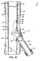
sleeve 34 has been shifted upward relative to theopening 32, so that access is now permitted through the opening. It will now be appreciated that thecement 24 is not placed between thepackers sleeve 34 is free to displace externally on thecasing 28. In this view it may also be seen that thesleeve 34 has aprofile 44 formed thereon, the profile including aninclined edge 46. - The
apparatus 30 now also includes adeflection device assembly 48, which has been installed in thecasing 28, for example, by conveying it downwardly through thecasing string 18 from the earth's surface. Thedeflection device assembly 48 includes a deflection device orwhipstock 50, and an optional anchoring device orpacker 52. When installed in thecasing 28, an upper laterallyinclined deflection surface 54 is radially oriented to face toward theopening 32. Such radial orientation may be accomplished by using a gyroscope, highside indicator, etc., according to conventional techniques. - Alternatively, the
deflection device assembly 48 may be engaged with ahelical orienting profile 56 of theapparatus 30. For example, aprojection 58 of theassembly 48 may engage theprofile 56 as the assembly is lowered into thecasing 28, thereby automatically orienting thesurface 54 to face toward theopening 32. If provided. thepacker 52 may then be set in thecasing 28 to anchor theassembly 48 therein and to aid in preventing debris from being trapped between theassembly 48 and thecasing 28. Note that the orientingprofile 56 may be used to orient the shifting tool (not shown). so that the shifting tool may properly engage theprofiles 38 through theopening 32 for displacing thesleeve 34 as described above. As representatively depicted herein, theprofile 56 is formed at a reduction of the inner diameter of thecasing 28, but other alignment profiles are commercially available which do not require a reduced inner diameter, and any of these may be used in place of theprofile 56. - In the configuration shown in FIG. 1B, one or more cutting tools, such as drill bits, reamers, etc. (not shown), may be lowered through the
casing string 18 and deflected laterally by thesurface 54 through theopening 32. In this manner, a second orlateral wellbore 60 may be drilled intersecting theparent wellbore 12. Of course, it is well known to deflect cutting tools off of a whipstock to drill a lateral wellbore, but themethod 10 permits drilling thelateral wellbore 60 through thecasing string 18, without the need to mill through thecasing 28, and without the need to form the casing out of a relatively weak, brittle, and/or expensive drillable material, such as fiber-reinforced resin, plastic, or aluminum, etc. - In FIG. 1C it may be seen that the
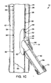
deflection device assembly 48 has been retrieved from within theapparatus 30. Aflange 62 and attached conduit orliner 64 have been installed in theapparatus 30, so that the liner extends outwardly from theopening 32. Theflange 62 andconduit 64 are shown as separate elements in FIG. 1C, however, it is to be clearly understood that they may be integrally formed, or may be made up of multiple elements, without departing from the principles of the present invention. - The
flange 62 andconduit 64 may also be conveyed into thecasing string 18 attached as shown in FIG. 1 C, or may be separately conveyed. For example, theflange 62 may be installed in thecasing 28 initially and theconduit 64 later attached to the flange. This could be accomplished by providing a conventional polished bore receptacle (not shown) on theflange 62 and sealingly engaging theconduit 64 with the receptacle. - The
flange 62 is shown in FIG. 1C as being made of metal, but it is to be clearly understood that the flange may be made of other materials. For example, to aid in passing theflange 62 through thecasing string 18. the flange could be made of an elastomeric material so that it could be "folded" or otherwise deformed if need be, until it is appropriately positioned within theapparatus 30. Such "folding" or other deforming of theflange 62 could also be accomplished if the flange were made of a deformable steel or other material. - A
portion 66 extends outwardly through theopening 32. The portion may be a portion of theflange 62 as shown in FIG. 1C, a portion of theconduit 64, or a separately formed portion of theapparatus 30. Theprofile 44 of thesleeve 34 is complementarily shaped relative to the exterior of theportion 66, for purposes that will be more fully described below. - The
flange 62 is positioned so that it contacts the interior of thecasing 28 sidewall about a periphery of theopening 32. Sealing engagement may be provided by aseal 68 carried on theflange 62. Alternatively, theflange 62 may be adhesively bonded to the periphery of theopening 32, otherwise engaged with the opening, etc. The sealing engagement between theflange 62 and thecasing 28 as shown in FIG. 1 C provides fluid isolation between the interior of the casing and theannulus 26, and between theliner 64 and the annulus. It will be readily appreciated that theflange 62 could additionally or alternatively sealingly engage the interior of thesleeve 34, for example, by appropriately positioning theseal 68 between the flange and the sleeve, adding another sealing device for this purpose, etc. - The
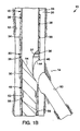
flange 62 may be biased into contact with thecasing 28. For example, an anchoring device orpacker 70 attached to theliner 64 may be utilized to exert a downwardly biasing force on the liner, thereby biasing theflange 62 against the interior surface of thecasing 28 and maintaining sealing engagement therebetween. Other methods of biasing theflange 62 are described below. - In FIG. 1D, it may be seen that the
sleeve 34 has been downwardly shifted relative to thecasing 28, as compared to that shown in FIG. 1 C. Theinclined edge 46 of theprofile 44 on thesleeve 34 is now engaged with theportion 66. Such engagement secures theflange 62 relative to thecasing 28, preventing relative movement therebetween, and may also bias theflange 62 into contact with thecasing 28. This biasing is due to engagement between theinclined edge 46 and a complementarily shapedrecess 72 formed on theportion 66. Of course, theedge 46 andrecess 72 may be otherwise shaped without departing from the principles of the present invention. - FIG. 1 D also shows an alternative configuration of the
opening 32, in which a lower portion of the opening engages theflange 62, thereby supporting the flange and further restricting lateral movement of the flange relative to thecasing 28. Although the lower portion of theopening 32 is shown in FIG. 1D as being generally tapered or wedge-shaped and complementarily engaging theportion 66, it is to be understood that other shapes and types of engagements may be utilized, without departing from the principles of the present invention. - In addition, note that FIG. 1 D shows an
optional projection 78 formed externally on theliner 64 opposite thecasing 28 from theflange 62. Theprojection 78 operates to enhance the structural integrity of the flange-to-casing engagement by further restricting lateral displacement of theflange 62 relative to thecasing 28, and by supporting the periphery of theopening 32.Additional projections 78 may be provided or may be continuously formed about the area where theportion 66 extends through the lower portion of theopening 32. Theprojection 78 is shown as having a generally semi-circular cross-section, but other shapes could be utilized, and the projection could be complementarily shaped relative to the exterior of thecasing 28, in keeping with the principles of the present invention. - Referring additionally now to FIG. 2, an enlarged cross-sectional view is shown of the interconnection between the
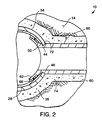
sleeve 34,flange 62,portion 66, andcasing 28. In this view it may be clearly seen that theprofile 44 engages therecess 72 to either side of theportion 66, and that this engagement applies an outwardly biasing force to theflange 62. This biasing force may be utilized to compress the seal 68 (shown in FIG. 2 in an optional form) between theflange 62 and the inner side surface of thecasing 28. - Note that this engagement also prevents relative motion between the
flange 62,portion 66 andliner 64. Thus,cement 74 forced into the space between theapparatus 30 and thewellbores - Referring again to FIG. 1D, note that an optional
hydraulic actuator 76 is shown attached to theapparatus 30. As representatively illustrated, thehydraulic actuator 76 is formed by differential piston areas on thecasing 28 andsleeve 34, so that fluid pressure applied within the casing will cause the sleeve to be biased downwardly. Of course, fluid pressure could be otherwise applied, such as via a control line extending to another part of the well, additional differential piston areas could be provided to bias the sleeve upwardly, and other types of hydraulic actuators could be provided, without departing from the principles of the present invention. - Referring additionally now to FIGS. 3A & 3B, another
method 80 of forming a wellbore junction is schematically and representatively illustrated. Elements which are similar to those previously described are indicated in FIGS. 3A & 3B using the same reference numbers, with an added suffix "a". - In the
method 80, thecasing string 18a includes one ormore centralizers 82 and anapparatus 84 for forming the wellbore junction. Theapparatus 84 includes a section ofcasing 86, asleeve 88 and a shielding device orenclosure 90 outwardly surrounding the sleeve. As with theapparatus 30 described above, thesleeve 88 may be shaped differently from that shown, may be displaceable relative to thecasing 86 in any of a variety of manners, may be internally or externally disposed relative to the casing, may be sealingly engaged with the casing, may have an actuator attached thereto, may include other profiles formed thereon, etc. In the configuration shown in FIG. 3A, thesleeve 88 is in a position in which it blocks access through theopening 32a. - The
enclosure 90 may be a membrane, may be made of an elastomeric material, may be similar in many respects to an inflatable packer element, and is radially outwardly extendable relative to thecasing 86. In themethod 80, theenclosure 90 prevents thesleeve 88 from contactingcement 24a flowed into theannulus 26a, and provides radial clearance about theapparatus 84. For this purpose, theenclosure 90 is externally and sealingly attached at its opposite ends to thecasing 86 above and below thesleeve 88. Aport 92 provides fluid communication between the interior of theenclosure 90 and the interior of thecasing 86. However, it is to be clearly understood that theenclosure 90 could be otherwise attached, made of different materials, such as metal, mechanically or otherwise extendable instead of inflatable. etc.. without departing from the principles of the present invention. - In FIG. 3B, the
apparatus 84 is shown with theenclosure 90 outwardly extended into sealing engagement with thewellbore 12a. To extend theenclosure 90. fluid pressure has been applied to the interior of thecasing 86, thereby inflating the enclosure via theport 92. Note, however, that it is not necessary in themethod 80 for theenclosure 90 to sealingly engage thewellbore 12a, for example, the enclosure could extend only partially radially between thecasing 86 and the wellbore. -
Cement 24a is flowed into theannulus 26a above and below theapparatus 84. Thecement 24a may be flowed into the annulus before theenclosure 90 is outwardly extended, so that the cement does not need to be flowed separately above and below the enclosure or otherwise "staged". If theenclosure 90 is outwardly extended, but does not sealingly engage thewellbore 12a, thecement 24a may also flow radially between theenclosure 90 and the wellbore. Thecement 24a is permitted to harden and thesleeve 88 is shifted upwardly relative to thecasing 86 to permit access through theopening 32a. Alateral wellbore 60a is then drilled by deflecting one or more cutting tools laterally through theopening 32a. For this purpose, and in a manner similar to that described above for themethod 10, a deflection device assembly may be installed in theapparatus 84 and oriented with respect thereto using an orienting profile 56a. - When the
lateral wellbore 60a is drilled, the cutting tool will cut through theenclosure 90, since it is positioned between theopening 32a and thewellbore 12a. After thelateral wellbore 60a has been drilled, a flange and liner may be installed as described above for themethod 10. Thesleeve 88 may include a profile, such as theprofile 44, for engaging, biasing and/or securing the flange or another portion as described above. In these respects, themethod 80 may be substantially similar to themethod 10, and will not be further described herein. However, it is to be clearly understood that themethod 80 may also differ in many respects from themethod 10, without departing from the principles of the present invention. - Referring additionally now to FIG. 4 another
method 100 of forming a wellbore junction is representatively and schematically illustrated. Elements which are similar to those previously described are indicated in FIG. 4 using the same reference numbers, with an added suffix "b". - The
method 100 is in many respects similar to themethod 80. However, in themethod 100, thecasing string 18b is decentralized in thewellbore 12b prior to flowing thecement 24b into theannulus 26b. For this purpose, decentralizers 102 are provided in anoverall apparatus 104 above and below theenclosure 90b.Standoffs 106 are provided opposite thedecentralizers 102, so that there is clearance about thesleeve 88b when the decentralizers are extended to decentralize theapparatus 104 within thewellbore 12b. - As depicted in FIG. 4, the
decentralizers 102 are made up of telescoping pistons which are radially outwardly extended by applying fluid pressure to the interior of thecasing 86b. It is to be clearly understood, however, that thedecentralizers 102 could be otherwise configured, for example, as hydraulically or mechanically actuated wedges, etc. - Note that fluid pressure may be applied to the interior of the
casing 86b to extend thedecentralizers 102, radially outwardly extend theenclosure 90b, and shift thesleeve 88b (if a hydraulic actuator is attached thereto). These may occur simultaneously or sequentially, for example, by utilizing shear members, such as shear pins, to delay actuation of one or more of these elements. - With the
decentralizers 102 andenclosure 90b extended, thecement 24b is flowed into theannulus 26b and permitted to harden. With thesleeve 88b shifted upward to permit access through theopening 32b, one or more cutting tools are deflected outwardly through the opening to cut through theenclosure 90b and drill thelateral wellbore 60b. A deflection device assembly may be used as described above for laterally deflecting the cutting tools. Decentralization of theapparatus 104 permits increased clearance between the apparatus and thewellbore 12b during this and subsequent operations. - After the
lateral wellbore 60b has been drilled, a flange and liner may be installed as described above for themethod 10. Thesleeve 88b may include a profile, such as theprofile 44, for engaging, biasing and/or securing the flange or another portion as described above. In these respects, themethod 100 may be substantially similar to themethod 10, and will not be further described herein. However. it is to be clearly understood that themethod 100 may also differ in many respects from themethod 10, without departing from the principles of the present invention. - It will be appreciated that the invention described above may be modified.
Claims (10)
- A method of forming a wellbore junction, comprising the steps of: drilling a first wellbore (12,12a,12b); positioning within the first wellbore (12,12a,12b) a tubular member (28,86,86b) having an opening (32,32a,32b) formed through a sidewall portion thereof; positioning a blocking member (34,88,88b) in a second position, the blocking member (34,88,88b) being selectively positionable relative to the opening (32,32a,32b) in a first position in which the blocking member (34,88,88b) blocks the opening (32,32a,32b) and in the second position in which the blocking member (34,88,88b) permits access to the opening (32,32a,32b); and drilling a second wellbore (60,60a,60b) by passing at least one cutting tool through the opening (32,32a,32b).
- A method according to Claim 1, further comprising the step of shifting the blocking member (34,88,88b) between its first and second positions after the tubular member positioning step.
- A method according to Claim 1 or 2, wherein the tubular member (88,88b) further comprises an outwardly extendable membrane (90,90b) surrounding the blocking member (88,88b).
- A method according to Claim 1, 2 or 3, further comprising the step of forcing the tubular member (86b) toward a sidewall of the first wellbore (12b), thereby decentralizing the tubular member (86b) within the first wellbore (12b).
- A method of forming a wellbore junction, comprising the steps of: disposing a blocking member (88,88b) relative to a tubular member (86,88a) having an opening (32a,32b) formed through a sidewall thereof, the blocking member (88,88b) being displaceable between a first position in which the blocking member (88,88b) prevents access through the opening (32a,32b), and a second position in which the blocking member (88,88b) permits access through the opening (32a,32b); disposing a shielding device externally relative to the blocking member (88,88b); positioning the tubular member (86,86b) within a first wellbore (12a,12b); positioning the blocking member (88,88b) in the second position; and passing at least one cutting tool through the opening (32a,32b), thereby drilling through the shielding device and drilling a second wellbore (60a,60b) intersecting the first wellbore (12a,12b).
- A method according to any preceding Claim, further comprising the step of engaging a flange (62) with the tubular member (28,86,86b) about a periphery of the opening (32,32a,32b).
- A method according to Claim 6, wherein the flange engaging step further comprises sealingly engaging the flange (62) with the tubular member (28,86,86b).
- Apparatus for forming a wellbore junction, comprising: a tubular member (28,86, 86b) having an opening (32,32a,32b) formed through a sidewall portion thereof; a blocking member (34,88,88b) selectively positionable relative to the opening (32,32a,32b) in a first position in which the blocking member (34,88,88b) blocks the opening (32,32a,32b), and a second position in which the blocking member (34,88,88b) permits access through the opening (32,32a,32b): and a deflection device assembly (48) including a deflection device (50) having an inclined surface (54) formed thereon. the surface being aligned relative to the opening (32.32a.32b).
- Apparatus for forming a wellbore junction, comprising: a tubular member (28,86,86b) having an opening (32,32a,32b) formed through a sidewall thereof; a blocking member (34,88,88b) displaceable relative to the tubular member (28,86,86b) and selectively permitting and preventing access through the opening (32,32a,32b); and a flange (62) sealingly engaged with the tubular member (28,86,86b) about a periphery of the opening (32,32a,32b).
- Apparatus for forming a wellbore junction, comprising: a tubular member (86,86b) having an opening (32a,32b) formed through a sidewall thereof; a blocking member (88,88b) displaceable relative to the tubular member (86,86b) and selectively permitting and preventing access through the opening (32a,32b); and an enclosure (90,90b) outwardly disposed relative to the blocking member (88,88b).
Applications Claiming Priority (2)
| Application Number | Priority Date | Filing Date | Title |
|---|---|---|---|
| US47042 | 1998-03-24 | ||
| US09/047,042 US6073697A (en) | 1998-03-24 | 1998-03-24 | Lateral wellbore junction having displaceable casing blocking member |
Publications (2)
| Publication Number | Publication Date |
|---|---|
| EP0945586A2 true EP0945586A2 (en) | 1999-09-29 |
| EP0945586A3 EP0945586A3 (en) | 2000-10-11 |
Family
ID=21946762
Family Applications (1)
| Application Number | Title | Priority Date | Filing Date |
|---|---|---|---|
| EP99302059A Withdrawn EP0945586A3 (en) | 1998-03-24 | 1999-03-17 | Method and apparatus for forming a wellbore junction |
Country Status (4)
| Country | Link |
|---|---|
| US (1) | US6073697A (en) |
| EP (1) | EP0945586A3 (en) |
| BR (1) | BR9901707A (en) |
| NO (1) | NO991402L (en) |
Cited By (5)
| Publication number | Priority date | Publication date | Assignee | Title |
|---|---|---|---|---|
| EP0961007A2 (en) * | 1998-05-28 | 1999-12-01 | Halliburton Energy Services, Inc. | Expandable wellbore junction |
| WO2001094746A1 (en) * | 2000-06-05 | 2001-12-13 | Weatherford/Lamb, Inc. | Wellbore liner system |
| GB2408761A (en) * | 2003-12-01 | 2005-06-08 | Halliburton Energy Serv Inc | Multilateral wellbore completion junction with an alternative passage to allow access to the bore below the junction |
| WO2014113012A1 (en) | 2013-01-18 | 2014-07-24 | Halliburton Energy Services, Inc. | Systems and methods of supporting a multilateral window |
| EP2286054A4 (en) * | 2008-05-21 | 2016-02-24 | Halliburton Energy Services Inc | Casing exit joint with easily milled, low density barrier |
Families Citing this family (28)
| Publication number | Priority date | Publication date | Assignee | Title |
|---|---|---|---|---|
| US6568469B2 (en) * | 1998-11-19 | 2003-05-27 | Schlumberger Technology Corporation | Method and apparatus for connecting a main well bore and a lateral branch |
| US6419026B1 (en) | 1999-12-08 | 2002-07-16 | Baker Hughes Incorporated | Method and apparatus for completing a wellbore |
| CA2409872C (en) * | 2000-05-22 | 2009-04-28 | Smith International, Inc. | Sealed lateral wellbore junction |
| US20020070027A1 (en) | 2000-12-08 | 2002-06-13 | Herve Ohmer | Method and apparatus for controlling well pressure in open-ended casing |
| US6868909B2 (en) | 2001-06-26 | 2005-03-22 | Baker Hughes Incorporated | Drillable junction joint and method of use |
| US6883611B2 (en) * | 2002-04-12 | 2005-04-26 | Halliburton Energy Services, Inc. | Sealed multilateral junction system |
| US6915847B2 (en) * | 2003-02-14 | 2005-07-12 | Schlumberger Technology Corporation | Testing a junction of plural bores in a well |
| US6913082B2 (en) * | 2003-02-28 | 2005-07-05 | Halliburton Energy Services, Inc. | Reduced debris milled multilateral window |
| US7793718B2 (en) | 2006-03-30 | 2010-09-14 | Schlumberger Technology Corporation | Communicating electrical energy with an electrical device in a well |
| US7712524B2 (en) * | 2006-03-30 | 2010-05-11 | Schlumberger Technology Corporation | Measuring a characteristic of a well proximate a region to be gravel packed |
| US8056619B2 (en) | 2006-03-30 | 2011-11-15 | Schlumberger Technology Corporation | Aligning inductive couplers in a well |
| US7992645B2 (en) * | 2008-02-20 | 2011-08-09 | Packers Plus Energy Services Inc. | Cut release sub and method |
| US9260921B2 (en) * | 2008-05-20 | 2016-02-16 | Halliburton Energy Services, Inc. | System and methods for constructing and fracture stimulating multiple ultra-short radius laterals from a parent well |
| US8430187B2 (en) * | 2009-02-27 | 2013-04-30 | Conocophillips Company | Directional sidetrack well drilling system |
| AU2010273790B2 (en) * | 2009-06-29 | 2015-04-02 | Halliburton Energy Services, Inc. | Wellbore laser operations |
| US8839850B2 (en) | 2009-10-07 | 2014-09-23 | Schlumberger Technology Corporation | Active integrated completion installation system and method |
| US8376054B2 (en) * | 2010-02-04 | 2013-02-19 | Halliburton Energy Services, Inc. | Methods and systems for orienting in a bore |
| US8505621B2 (en) | 2010-03-30 | 2013-08-13 | Halliburton Energy Services, Inc. | Well assembly with recesses facilitating branch wellbore creation |
| US8371368B2 (en) * | 2010-03-31 | 2013-02-12 | Halliburton Energy Services, Inc. | Well assembly with a millable member in an opening |
| US9234613B2 (en) | 2010-05-28 | 2016-01-12 | Halliburton Energy Services, Inc. | Well assembly coupling |
| US9200482B2 (en) | 2011-06-03 | 2015-12-01 | Halliburton Energy Services, Inc. | Wellbore junction completion with fluid loss control |
| US8701775B2 (en) | 2011-06-03 | 2014-04-22 | Halliburton Energy Services, Inc. | Completion of lateral bore with high pressure multibore junction assembly |
| US8967277B2 (en) | 2011-06-03 | 2015-03-03 | Halliburton Energy Services, Inc. | Variably configurable wellbore junction assembly |
| US9249559B2 (en) | 2011-10-04 | 2016-02-02 | Schlumberger Technology Corporation | Providing equipment in lateral branches of a well |
| US9644476B2 (en) | 2012-01-23 | 2017-05-09 | Schlumberger Technology Corporation | Structures having cavities containing coupler portions |
| US9175560B2 (en) | 2012-01-26 | 2015-11-03 | Schlumberger Technology Corporation | Providing coupler portions along a structure |
| US9938823B2 (en) | 2012-02-15 | 2018-04-10 | Schlumberger Technology Corporation | Communicating power and data to a component in a well |
| US10036234B2 (en) | 2012-06-08 | 2018-07-31 | Schlumberger Technology Corporation | Lateral wellbore completion apparatus and method |
Citations (6)
| Publication number | Priority date | Publication date | Assignee | Title |
|---|---|---|---|---|
| US5458209A (en) * | 1992-06-12 | 1995-10-17 | Institut Francais Du Petrole | Device, system and method for drilling and completing a lateral well |
| US5484017A (en) * | 1995-01-12 | 1996-01-16 | Baker Hughes Incorporated | Whipstock assembly for a sleeved casing |
| US5566763A (en) * | 1994-08-26 | 1996-10-22 | Halliburton Company | Decentralizing, centralizing, locating and orienting subsystems and methods for subterranean multilateral well drilling and completion |
| GB2316424A (en) * | 1996-08-13 | 1998-02-25 | Baker Hughes Inc | Pre-machined window for use in drilling lateral boreholes |
| WO1998009054A1 (en) * | 1996-08-30 | 1998-03-05 | Baker Hughes Incorporated | Cement reinforced inflatable seal for a junction of a multilateral |
| WO1998009053A2 (en) * | 1996-08-30 | 1998-03-05 | Baker Hughes Incorporated | Method and apparatus for sealing a junction on a multilateral well |
Family Cites Families (7)
| Publication number | Priority date | Publication date | Assignee | Title |
|---|---|---|---|---|
| US5474131A (en) * | 1992-08-07 | 1995-12-12 | Baker Hughes Incorporated | Method for completing multi-lateral wells and maintaining selective re-entry into laterals |
| GB2297779B (en) * | 1992-08-07 | 1996-10-09 | Baker Hughes Inc | Method & apparatus for sealing the juncture between a vertical and horizontal well |
| US5462120A (en) * | 1993-01-04 | 1995-10-31 | S-Cal Research Corp. | Downhole equipment, tools and assembly procedures for the drilling, tie-in and completion of vertical cased oil wells connected to liner-equipped multiple drainholes |
| US5564503A (en) * | 1994-08-26 | 1996-10-15 | Halliburton Company | Methods and systems for subterranean multilateral well drilling and completion |
| US5787987A (en) * | 1995-09-06 | 1998-08-04 | Baker Hughes Incorporated | Lateral seal and control system |
| US5918669A (en) * | 1996-04-26 | 1999-07-06 | Camco International, Inc. | Method and apparatus for remote control of multilateral wells |
| US5803178A (en) * | 1996-09-13 | 1998-09-08 | Union Oil Company Of California | Downwell isolator |
-
1998
- 1998-03-24 US US09/047,042 patent/US6073697A/en not_active Expired - Lifetime
-
1999
- 1999-03-17 EP EP99302059A patent/EP0945586A3/en not_active Withdrawn
- 1999-03-23 NO NO991402A patent/NO991402L/en not_active Application Discontinuation
- 1999-03-24 BR BR9901707-5A patent/BR9901707A/en not_active Application Discontinuation
Patent Citations (6)
| Publication number | Priority date | Publication date | Assignee | Title |
|---|---|---|---|---|
| US5458209A (en) * | 1992-06-12 | 1995-10-17 | Institut Francais Du Petrole | Device, system and method for drilling and completing a lateral well |
| US5566763A (en) * | 1994-08-26 | 1996-10-22 | Halliburton Company | Decentralizing, centralizing, locating and orienting subsystems and methods for subterranean multilateral well drilling and completion |
| US5484017A (en) * | 1995-01-12 | 1996-01-16 | Baker Hughes Incorporated | Whipstock assembly for a sleeved casing |
| GB2316424A (en) * | 1996-08-13 | 1998-02-25 | Baker Hughes Inc | Pre-machined window for use in drilling lateral boreholes |
| WO1998009054A1 (en) * | 1996-08-30 | 1998-03-05 | Baker Hughes Incorporated | Cement reinforced inflatable seal for a junction of a multilateral |
| WO1998009053A2 (en) * | 1996-08-30 | 1998-03-05 | Baker Hughes Incorporated | Method and apparatus for sealing a junction on a multilateral well |
Cited By (12)
| Publication number | Priority date | Publication date | Assignee | Title |
|---|---|---|---|---|
| US6547006B1 (en) | 1996-05-02 | 2003-04-15 | Weatherford/Lamb, Inc. | Wellbore liner system |
| US6766859B2 (en) | 1996-05-02 | 2004-07-27 | Weatherford/Lamb, Inc. | Wellbore liner system |
| US7025144B2 (en) | 1996-05-02 | 2006-04-11 | Weatherford/Lamb, Inc. | Wellbore liner system |
| EP0961007A2 (en) * | 1998-05-28 | 1999-12-01 | Halliburton Energy Services, Inc. | Expandable wellbore junction |
| EP0961007A3 (en) * | 1998-05-28 | 2000-08-02 | Halliburton Energy Services, Inc. | Expandable wellbore junction |
| WO2001094746A1 (en) * | 2000-06-05 | 2001-12-13 | Weatherford/Lamb, Inc. | Wellbore liner system |
| GB2408761A (en) * | 2003-12-01 | 2005-06-08 | Halliburton Energy Serv Inc | Multilateral wellbore completion junction with an alternative passage to allow access to the bore below the junction |
| US7159661B2 (en) | 2003-12-01 | 2007-01-09 | Halliburton Energy Services, Inc. | Multilateral completion system utilizing an alternate passage |
| GB2408761B (en) * | 2003-12-01 | 2007-10-17 | Halliburton Energy Serv Inc | Multilateral completion system utilizing an alternative passage |
| EP2286054A4 (en) * | 2008-05-21 | 2016-02-24 | Halliburton Energy Services Inc | Casing exit joint with easily milled, low density barrier |
| WO2014113012A1 (en) | 2013-01-18 | 2014-07-24 | Halliburton Energy Services, Inc. | Systems and methods of supporting a multilateral window |
| EP2912255A4 (en) * | 2013-01-18 | 2016-07-27 | Halliburton Energy Services Inc | Systems and methods of supporting a multilateral window |
Also Published As
| Publication number | Publication date |
|---|---|
| NO991402L (en) | 1999-09-27 |
| US6073697A (en) | 2000-06-13 |
| NO991402D0 (en) | 1999-03-23 |
| EP0945586A3 (en) | 2000-10-11 |
| BR9901707A (en) | 2000-01-18 |
Similar Documents
| Publication | Publication Date | Title |
|---|---|---|
| US6073697A (en) | Lateral wellbore junction having displaceable casing blocking member | |
| US5564503A (en) | Methods and systems for subterranean multilateral well drilling and completion | |
| EP1295011B1 (en) | Apparatus and method to complete a multilateral junction | |
| US7000703B2 (en) | Sealed multilateral junction system | |
| CA2272680C (en) | Expandable wellbore junction | |
| EP1042587B1 (en) | System for drilling and completing multilateral wells | |
| US7000704B2 (en) | Latch profile installation in existing casing | |
| US6786283B2 (en) | Methods and associated apparatus for drilling and completing a wellbore junction | |
| US6009949A (en) | Apparatus and methods for sealing a wellbore junction | |
| AU752761B2 (en) | Apparatus and methods for sealing a wellbore junction |
Legal Events
| Date | Code | Title | Description |
|---|---|---|---|
| PUAI | Public reference made under article 153(3) epc to a published international application that has entered the european phase |
Free format text: ORIGINAL CODE: 0009012 |
|
| AK | Designated contracting states |
Kind code of ref document: A2 Designated state(s): AT BE CH CY DE DK ES FI FR GB GR IE IT LI LU MC NL PT SE |
|
| AX | Request for extension of the european patent |
Free format text: AL;LT;LV;MK;RO;SI |
|
| RIN1 | Information on inventor provided before grant (corrected) |
Inventor name: LONGBOTTOM, JIM R. Inventor name: GANO, JOHN C. Inventor name: DALE, DANA R. Inventor name: FREEMAN, TOMMIE A. Inventor name: PARLIN, JOSEPH D. |
|
| PUAL | Search report despatched |
Free format text: ORIGINAL CODE: 0009013 |
|
| AK | Designated contracting states |
Kind code of ref document: A3 Designated state(s): AT BE CH CY DE DK ES FI FR GB GR IE IT LI LU MC NL PT SE |
|
| AX | Request for extension of the european patent |
Free format text: AL;LT;LV;MK;RO;SI |
|
| RIC1 | Information provided on ipc code assigned before grant |
Free format text: 7E 21B 7/06 A, 7E 21B 33/10 B |
|
| AKX | Designation fees paid | ||
| REG | Reference to a national code |
Ref country code: DE Ref legal event code: 8566 |
|
| STAA | Information on the status of an ep patent application or granted ep patent |
Free format text: STATUS: THE APPLICATION IS DEEMED TO BE WITHDRAWN |
|
| 18D | Application deemed to be withdrawn |
Effective date: 20010412 |