EP0945250A2 - Machine for making a sheet of single-face corrugated paperboard and a production line incorporating such a machine - Google Patents
Machine for making a sheet of single-face corrugated paperboard and a production line incorporating such a machine Download PDFInfo
- Publication number
- EP0945250A2 EP0945250A2 EP99105233A EP99105233A EP0945250A2 EP 0945250 A2 EP0945250 A2 EP 0945250A2 EP 99105233 A EP99105233 A EP 99105233A EP 99105233 A EP99105233 A EP 99105233A EP 0945250 A2 EP0945250 A2 EP 0945250A2
- Authority
- EP
- European Patent Office
- Prior art keywords
- sided
- strip
- corrugated cardboard
- paper
- strips
- Prior art date
- Legal status (The legal status is an assumption and is not a legal conclusion. Google has not performed a legal analysis and makes no representation as to the accuracy of the status listed.)
- Withdrawn
Links
Images


Classifications
-
- B—PERFORMING OPERATIONS; TRANSPORTING
- B31—MAKING ARTICLES OF PAPER, CARDBOARD OR MATERIAL WORKED IN A MANNER ANALOGOUS TO PAPER; WORKING PAPER, CARDBOARD OR MATERIAL WORKED IN A MANNER ANALOGOUS TO PAPER
- B31F—MECHANICAL WORKING OR DEFORMATION OF PAPER, CARDBOARD OR MATERIAL WORKED IN A MANNER ANALOGOUS TO PAPER
- B31F1/00—Mechanical deformation without removing material, e.g. in combination with laminating
- B31F1/20—Corrugating; Corrugating combined with laminating to other layers
- B31F1/24—Making webs in which the channel of each corrugation is transverse to the web feed
- B31F1/26—Making webs in which the channel of each corrugation is transverse to the web feed by interengaging toothed cylinders cylinder constructions
- B31F1/28—Making webs in which the channel of each corrugation is transverse to the web feed by interengaging toothed cylinders cylinder constructions combined with uniting the corrugated webs to flat webs ; Making double-faced corrugated cardboard
- B31F1/2813—Making corrugated cardboard of composite structure, e.g. comprising two or more corrugated layers
-
- B—PERFORMING OPERATIONS; TRANSPORTING
- B31—MAKING ARTICLES OF PAPER, CARDBOARD OR MATERIAL WORKED IN A MANNER ANALOGOUS TO PAPER; WORKING PAPER, CARDBOARD OR MATERIAL WORKED IN A MANNER ANALOGOUS TO PAPER
- B31F—MECHANICAL WORKING OR DEFORMATION OF PAPER, CARDBOARD OR MATERIAL WORKED IN A MANNER ANALOGOUS TO PAPER
- B31F1/00—Mechanical deformation without removing material, e.g. in combination with laminating
- B31F1/20—Corrugating; Corrugating combined with laminating to other layers
- B31F1/24—Making webs in which the channel of each corrugation is transverse to the web feed
- B31F1/26—Making webs in which the channel of each corrugation is transverse to the web feed by interengaging toothed cylinders cylinder constructions
- B31F1/28—Making webs in which the channel of each corrugation is transverse to the web feed by interengaging toothed cylinders cylinder constructions combined with uniting the corrugated webs to flat webs ; Making double-faced corrugated cardboard
- B31F1/2804—Methods
Definitions
- the present invention relates to a single-sided machine for the production of corrugated cardboard strips and a line of manufacturing comprising such a machine.
- corrugated cardboard For the manufacture of corrugated cardboard, generally used a machine known as single face to form corrugations on a first strip of paper and then after gluing the ridges of ripples, apply a strip of cover paper over them to give what is called a strip of single-sided corrugated cardboard.
- These single-sided machines generally include two cylinders fluted, an upper fluted cylinder and a lower fluted cylinder.
- the first strip of paper goes around part of the circumference of the upper grooved cylinder before being introduced into the area between the upper grooved cylinder and the cylinder lower grooved. This wavy strip then wraps around a part of the circumference of the lower grooved cylinder where the crests of ripples will be glued.
- a strip of paper cover will be applied, with pressure, on the crests of the undulations, previously glued, using a smooth cylinder, called a smooth press, around a part of the circumference of which the strip of winding cover paper.
- This corrugated cardboard manufacturing operation single-sided is effected by means of grooved cylinders and a cylinder smooth heated.
- the upper and lower grooved cylinders are in general arranged so as to be able to keep the corrugated strip applied in the grooves of the cylinders.
- Auxiliary heating devices are also provided for maintain the strip of single-sided corrugated cardboard thus produced at a sufficient temperature to ensure adequate drying of the adhesive that we deposited on the ridges ripples.
- the single-sided machines described in the various publications mentioned above are intended to produce cardboard single-sided corrugated at production speeds of around 300m / min and more. At these speeds, various problems arise for the manufacturer.
- One of these problems caused in particular by the speeds of high rotation of the different cylinders, lies in the appearance significant vibrations generating a sound level of very high functioning requiring important anti-noise protections.
- Another problem, from the same source, is wear and tear important fluted cylinders.
- An additional problem, always coming from the same source lies in the impossibility of using strips of corrugated paper as well as strips of paper relatively low grammage coverage due to the risk of rupture, by excessive traction and pressure on them during their passage between the lower grooved cylinder and the smooth cylinder of the press smooth.
- Another important problem also caused by high operating speeds, refers to the heat transfer time the strips of paper to be processed.
- a corrugated line is intended to produce corrugated cardboard in different forms, i.e. to produce single-sided corrugated cardboard, double-sided corrugated cardboard side, which is obtained by gluing together two strips of corrugated cardboard single sided, and possibly triple corrugated or quadruple sided.
- single-sided corrugated cardboard double-sided corrugated cardboard side
- two strips of corrugated cardboard single sided we use several single sided machines, one machine per single-sided tape, and the strips are superimposed by gluing produced to obtain the desired type of corrugated board.
- the strips of corrugated cardboard is then cut to the required size, and stacked to be issued to their user.
- the strip of single-sided corrugated cardboard emerging from a single-sided machine is treated individually when you want to obtain single-sided corrugated cardboard.
- the corrugations of the cardboard strip single-sided corrugated coming out of the single-sided machine are glued and covered with a second cover strip by means of a gluer, they are then dried in a drying device, then grooved and split longitudinally to the desired lateral format by a machine commonly called machine gun.
- a machine gun commonly called machine gun.
- slitting longitudinal of the cardboard strip produces two dimensional strips which are then separated and directed, on two levels, in direction of a cross cutter which will cut transversely each of the strips of cardboard in the desired longitudinal format.
- the plaques of corrugated cardboard thus obtained are then sent to two separate stackers, one for one of the plate sizes and the other for the second format of plates.
- the object of the present invention is to remedy the aforementioned drawbacks.
- the object of the invention is constituted by a machine single sided in accordance with claim 1 as well as the use of such a machine in a cardboard production line corrugated.
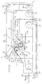
- Figure 1 is a schematic view of a first version a single-sided machine 1 which includes two lateral frames 2, 3 comprising bearings for supporting an upper grooved cylinder 4, a intermediate grooved cylinder 5 and a lower grooved cylinder 6.
- the upper grooved cylinder 4 is arranged to be able to apply, by means of a vaccine, the ripples formed in the meshing zone 7 between the upper grooved cylinder 4 and the intermediate grooved cylinder 5 against its grooves, this on at least part of its circumference.
- the lower grooved cylinder 6 is also arranged, like the cylinder upper grooved 4, in order to be able to apply, by means of a vaccine, the corrugations, formed in the meshing zone 8 between the cylinder lower grooved 6 and the intermediate grooved cylinder 5, against its grooves, this over at least part of its circumference.
- a first strip of paper waving 9 taking a coil 10 is conducted, after passing around deflection rollers 11, 12, between the lower grooved cylinder 6 and the intermediate grooved cylinder 5 in the engagement zone 8.
- a cover strip 14 taken from a reel 15 will be applied against the tips of the grooves by means of a smooth press 16.
- the smooth press shown here is a smooth press well known to machine builders. It is well understood that this smooth press could be of another type, also well known to machine builders, for example a smooth press using metal belts instead of a smooth cylinder.
- This strip of corrugated cardboard 19 is then routed towards the organs following the production line passing around the rollers return 20, 21, 22, 23 and 24.
- Return rollers 22 and 23 are located in a pit 36 arranged in the foundation supporting the machine single sided 1.
- Return rollers 20 to 23 are smooth rollers whereas roller 24 is a special roller, generally made of material plastic, called "non crush roll" by specialists.
- This roll 24 is so chosen to avoid crushing the corrugations of the cardboard strip corrugated 19 which are, in this place in contact with its circumference then that around the other return rollers 20 to 23, it is the paper strip cover 14 which is in contact with their circumference thus avoiding direct crushing of the grooves. It should be noted that, if necessary, the various idler rollers used could also be heated.
- a second strip of corrugating paper 25, taken from a coil 26 is driven, after passing around idler rollers 11, 12, between the upper grooved cylinder 4 and the grooved cylinder intermediate 5 in the meshing zone 7.
- This second strip of corrugating paper 25, having been corrugated during its passage in the zone meshing 7, wraps around part of the circumference of the upper grooved cylinder 4, part of the circumference in which the tips of the corrugations will be glued using a device sizing 26, which in this embodiment is a sizing device with a bubbler roller associated with an applicator roller.
- a device sizing 26 which in this embodiment is a sizing device with a bubbler roller associated with an applicator roller.
- the sizing device 13 for the strip of corrugating paper 9 can be made in the same way as the sizing device 26 for the second strip of corrugating paper 25.
- This corrugated strip 30 is then routed to the following organs of the line manufacturing by passing around a deflection roller 33.
- the roller reference 33 is a smooth roller. It should be noted that, if necessary, the various used idler rollers could also be heated.
- Figure 2 is a schematic view of a second version of a single-sided machine 1 in which the grooved cylinder intermediate 37 is much smaller in diameter than the cylinder intermediate grooved 5 in Figure 1.
- This choice is dictated by the desire to decrease in the best proportions the number of splines in engagement in mesh zones 7 and 8 so as to reduce stresses mechanical undergone by the strip of paper to be corrugated.
- the theory followed to come up with the solution of using a grooved cylinder small diameter intermediate is well known to manufacturers of machines that seek to decrease the length of the labyrinth formed by grooves of the cylinders in their engagement zone.
- the second strip of cover paper 25 passes around a roll of return 38 so as to guide it to the engagement zone 7 between the upper grooved cylinder 4 and the intermediate cylinder 37.
- Figure 3 is a schematic view, in the form of a block diagram, of a first version of a cardboard production line single-sided corrugated using a single-sided machine 1 identical to those previously described in Figures 1 or 2.
- the reference numbers 10, 15, 26 and 28 are relate to the paper reels.
- Reference numbers 9 and 27 are relate to the strips of paper to be corrugated.
- Reference numbers 14 and 25 relate to the strips of cover paper and the numbers references 19 and 30 relate to the strips of corrugated cardboard leaving the single-sided machine 1.
- the corrugated cardboard strips 19 and 30, represented graphically at 47 and 48 are routed to a preheater 39, which also receives strips of paper cover 40 and 41 taken from coils 42 and 43. These different strips 19, 30, 40 and 41 are then introduced into a gluing machine 44 in which the corrugated strips 19 and 30 will each be covered with a cover strip 40, respectively 41 to form two separate strips of single-sided corrugated cardboard 45 and 46 shown graphically at 49 and 50.
- each strip of single-sided corrugated cardboard 45 and 46 will be separated longitudinally to produce four strips 56, 57, 58, 59 of possibly different widths corresponding to one of the coordinates, width, desired format for cardboard plates corrugated harvested at the exit of the production line.
- Another advantage of the solution which has just been described resides in the fact that a speed reduction of a third compared to the speed conventional machines, for example, would already provide acceptable operating conditions and would allow an increase from production line production to values never before achieved.
- Figure 4 is a schematic view, in the form of a block diagram of a production line for double-sided corrugated cardboard using a single-sided machine 1 identical to those previously described in Figures 1 or 2.
- the reference numbers 10, 15, 26 and 28 are relate to the paper reels.
- Reference numbers 9 and 27 are relate to the strips of paper to be corrugated.
- Reference numbers 14 and 25 relate to the strips of cover paper and the numbers references 19 and 30 relate to the strips of corrugated cardboard leaving the single-sided machine 1.
- the corrugated cardboard strips 19 and 30, represented graphically at 47 and 48 are routed to a preheater 39, which also receives a strip of paper cover 41 taken from a coil 43.
- the double-sided corrugated cardboard strip 66 will be separated longitudinally to produce two strips 70 and 71 of widths possibly different corresponding to one of the coordinates, the width, of the desired format for the corrugated cardboard plates harvested by leaving the production line. These two bands 70 and 71 are then transferred to the cross cutter 55 two-stage. The band of double-sided corrugated cardboard 66 will be cut to length desired by the cross cutter 55. At the exit of the cross cutter 55, we obtain double-sided corrugated cardboard, of two formats different, on two passage levels 60 and 61. Finally, the passage level 60 double-sided corrugated sheets are stacked in stacker 64 and those of passage level 61 are stacked in a second stacker 65.
- Figure 5 is a schematic view, in the form of a block diagram, of a second version of a cardboard production line single-sided corrugated using a single-sided machine 1 identical to those previously described in Figures 1 or 2.
- the reference numbers 10, 15, 26 and 28 are relate to the paper reels.
- Reference numbers 9 and 27 are relate to the strips of paper to be corrugated.
- Reference numbers 14 and 25 relate to the strips of cover paper and the numbers references 19 and 30 relate to the strips of corrugated cardboard leaving the single-sided machine 1.
- the corrugated cardboard strips 19 and 30, represented graphically at 47 and 48 are routed to a preheater 39, which also receives strips of paper cover 40 and 41 taken from coils 42 and 43. These different strips 19, 30, 40 and 41 are then introduced into a gluing machine 44 in which the corrugated strips 19 and 30 will each be covered with a cover strip 40, respectively 41 to form two separate strips of single-sided corrugated cardboard 45 and 46 shown graphically at 49 and 50.
- each strip 45 and 46 represented graphically at 52 is introduced into a cutter rotary also comprising a first stage 53 and a second stage 53a, rotary cutter in which the lateral edges of each strip 45 and 46 will be cropped.
- the two strips of single-sided corrugated cardboard 45 and 46 will be introduced into a longitudinal cutting and grooving station comprising a first stage 54 and a second stage 54a.
- each strip of single-sided corrugated cardboard 45 and 46 will be separated longitudinally to produce four strips 56, 57, 58, 59 of width possibly different corresponding to one of the coordinates, the width, of the desired format for the corrugated cardboard plates harvested by leaving the production line. These four bands are then transferred to a two-stage cross cutter 55, respectively 55a. Single-sided corrugated cardboard strips 56 to 59 will be cut to the length of the format desired by the cross cutter. At the exit of the cross cutter we obtain cardboard plates corrugated single sided, in four different formats, on four levels of passage 60, 60a, 61 and 61a. The graphic representation of the plates of corrugated cardboard is shown in 63.
- the cardboard plates corrugated single sided passage level 60 are stacked in the stacker 64, those of passage level 60a are stacked in a second stacker 64a, those of passage level 61 are stacked in a third stacker 65 and those of passage level 61a are stacked in a fourth stacker 65a.
- Figure 6 is a schematic view, in the form of a block diagram, of a third version of a single-sided corrugated cardboard production line using a single-sided machine 1 identical to those previously described in Figures 1 or 2.
- the reference numbers 10, 15, 26 and 28 are relate to the paper reels.
- Reference numbers 9 and 27 are relate to the strips of paper to be corrugated.
- Reference numbers 14 and 25 relate to the strips of cover paper and the numbers references 19 and 30 relate to the strips of corrugated cardboard leaving the single-sided machine 1.
- the corrugated cardboard strips 19 and 30, represented graphically at 47 and 48 are routed to a preheater 39, which also receives strips of paper cover 40 and 41 taken from coils 42 and 43. These different strips 19, 30, 40 and 41 are then introduced into a gluing machine 44 in which the corrugated strips 19 and 30 will each be covered with a cover strip 40, respectively 41 to form two separate strips of single-sided corrugated cardboard 45 and 46.
- the strip of single-sided corrugated board 45 is introduced into a first station drying 51b while the strip 46 only crosses it without being dried.
- Band 46 is in turn introduced into a second station dryer 51c not treating the strip 45.
- each strip 45 and 46 is introduced into a first rotary cutter 53b and a second rotary cutter 53c, the first rotary cutter 53b working band 45 and the second rotary cutter working the band 46.
- the two strips of single-sided corrugated cardboard 45 and 46 will be introduced in a first longitudinal cutting station and grooving 54b and in a second longitudinal cutting station and grooving 54c.
- the strip of single-sided corrugated cardboard 45 will be separated longitudinally, to produce two bands 56 and 57, by the first rotary cutter 54b, this at possibly different widths corresponding to one of the coordinates, the width, of the desired format for the corrugated sheets harvested at the exit of the line manufacturing.
- the strip of single-sided corrugated cardboard 46 will be separated longitudinally, to produce two bands 58 and 59, by the second 54c rotary cutter, this at possibly different widths corresponding to one of the coordinates, the width, of the desired format for the corrugated sheets harvested at the exit of the line manufacturing.
- These four bands 56 to 59 are then transferred two to two in a first two-stage cross cutter 55b and in a second two-stage cross cutter 55c.
- Bands 56 and 57 will be cut to the length of the format desired by the first 55b rotary cutter and strips 58 and 59 will be cut to length of the format desired by the second cross cutter 55c.
- cross cutters we obtain single-sided corrugated cardboard sheets, in four different formats, on four passage levels 60b, 60c, 61b and 61c.
- the graphical representation of the corrugated sheets is shown in 63.
- the single-sided corrugated sheets of the passage level 60b are stacked in stacker 64b, those of passage level 60c are stacked in a second stacker 64c, those of passage level 61b are stacked in a third stacker 65b and those of passage level 61c are stacked in a fourth stacker 65c.
Abstract
Description
La présente invention se rapporte à une machine simple face pour la fabrication de bandes de carton ondulé et à une ligne de fabrication comportant une telle machine.The present invention relates to a single-sided machine for the production of corrugated cardboard strips and a line of manufacturing comprising such a machine.
Pour la fabrication du carton ondulé, on utilise généralement une machine dite simple face pour former des ondulations sur une première bande de papier et pour ensuite, après encollage des crêtes des ondulations, appliquer sur celles-ci une bande de papier de couverture pour donner ce que l'on appelle une bande de carton ondulé simple face. Ces machines simple face comprennent en général deux cylindres cannelés, un cylindre cannelé supérieur et un cylindre cannelé inférieur. La première bande de papier passe autour d'une partie de la circonférence du cylindre cannelé supérieur avant d'être introduite dans la zone d'engrènement située entre le cylindre cannelé supérieur et le cylindre cannelé inférieur. Cette bande ondulée s'enroule ensuite autour d'une partie de la circonférence du cylindre cannelé inférieur où les crêtes des ondulations seront encollées. Finalement, une bande de papier de couverture sera appliquée, avec pression, sur les crêtes des ondulations, préalablement encollées, à l'aide d'un cylindre lisse, appelé presse lisse, autour d'une partie de la circonférence duquel s'enroule la bande de papier de couverture. Cette opération de fabrication de carton ondulé simple face s'effectue au moyen de cylindres cannelés et d'un cylindre lisse chauffés. Les cylindres cannelés supérieur et inférieur sont en général agencés de façon à pouvoir maintenir la bande ondulée appliquée dans les cannelures des cylindres. A cet effet, on peut utiliser soit un dispositif d'aspiration de la bande cannelée contre les cannelures des cylindres, tel que celui décrit dans le brevet US 4,338,154, soit un dispositif de mise en pression de la bande cannelée contre les cannelures des cylindres tel que celui décrit dans le brevet US 4,261,784. For the manufacture of corrugated cardboard, generally used a machine known as single face to form corrugations on a first strip of paper and then after gluing the ridges of ripples, apply a strip of cover paper over them to give what is called a strip of single-sided corrugated cardboard. These single-sided machines generally include two cylinders fluted, an upper fluted cylinder and a lower fluted cylinder. The first strip of paper goes around part of the circumference of the upper grooved cylinder before being introduced into the area between the upper grooved cylinder and the cylinder lower grooved. This wavy strip then wraps around a part of the circumference of the lower grooved cylinder where the crests of ripples will be glued. Finally, a strip of paper cover will be applied, with pressure, on the crests of the undulations, previously glued, using a smooth cylinder, called a smooth press, around a part of the circumference of which the strip of winding cover paper. This corrugated cardboard manufacturing operation single-sided is effected by means of grooved cylinders and a cylinder smooth heated. The upper and lower grooved cylinders are in general arranged so as to be able to keep the corrugated strip applied in the grooves of the cylinders. For this purpose, either a device for suction of the grooved strip against the grooves of the cylinders, such as that described in US Patent 4,338,154, or a device for pressurizing the grooved strip against the grooves cylinders such as that described in US Pat. No. 4,261,784.
Des dispositifs auxiliaires de chauffage sont aussi prévus pour maintenir la bande de carton ondulé simple face ainsi réalisée à une température suffisante pour assurer un séchage adéquat de la colle que l'on a déposée sur les crêtes des ondulations. On connaít également des machines simple face dans lesquelles, pour améliorer la formation des ondulations, on utilise un jeu de trois, voir quatre, cylindres cannelés. De telles solutions ont été décrites dans les brevets US 2,429,482, US 5,419,796 et US 5,628,865.Auxiliary heating devices are also provided for maintain the strip of single-sided corrugated cardboard thus produced at a sufficient temperature to ensure adequate drying of the adhesive that we deposited on the ridges ripples. We also know single-sided machines in which, to improve the formation of corrugations, we use a set of three, see four, fluted cylinders. Of such solutions have been described in US Patents 2,429,482, US 5,419,796 and US 5,628,865.
Les machines simple face décrites dans les diverses publications mentionnées ci-avant sont destinées à produire du carton ondulé simple face à des vitesses de production de l'ordre de 300m/min et plus. A ces vitesses, différents problèmes se présentent au constructeur. L'un de ces problèmes, provoqués en particulier par les vitesses de rotation élevées des différents cylindres, réside dans l'apparition d'importantes vibrations génératrices d'un niveau sonore de fonctionnement très élévé nécessitant d'importantes protections anti-bruit. Un autre problème, provenant de la même source, est constitué par l'usure importante des cylindres cannelés. Un problème supplémentaire, provenant toujours de la même source, réside dans l'impossibilité d'utiliser des bandes de papier à onduler ainsi que des bandes de papier de couverture d'un grammage relativement faible en raison du risque de rupture, par traction et pression excessives sur ceux-ci lors de leur passage entre le cylindre cannelé inférieur et le cylindre lisse de la presse lisse. Un autre problème important, lui aussi provoqué par les hautes vitesses de fonctionnement, se rapporte au temps de transfert de chaleur aux bandes de papier devant être traitées.The single-sided machines described in the various publications mentioned above are intended to produce cardboard single-sided corrugated at production speeds of around 300m / min and more. At these speeds, various problems arise for the manufacturer. One of these problems, caused in particular by the speeds of high rotation of the different cylinders, lies in the appearance significant vibrations generating a sound level of very high functioning requiring important anti-noise protections. Another problem, from the same source, is wear and tear important fluted cylinders. An additional problem, always coming from the same source, lies in the impossibility of using strips of corrugated paper as well as strips of paper relatively low grammage coverage due to the risk of rupture, by excessive traction and pressure on them during their passage between the lower grooved cylinder and the smooth cylinder of the press smooth. Another important problem, also caused by high operating speeds, refers to the heat transfer time the strips of paper to be processed.
En raison des contraintes mécaniques engendrées par les vitesses de fonctionnement élevées, la construction des machines simple face, ainsi que celle des appareils utilisés conjointement avec celles-ci dans une ligne de production de carton ondulé est toujours une construction lourde et massive, par conséquent onéreuse. Due to the mechanical stresses caused by high operating speeds, simple machine construction face, as well as that of the devices used in conjunction with them in a corrugated board production line is always a heavy and massive construction, therefore expensive.
En général, une ligne de fabrication de carton ondulé est destinée à produire du carton ondulé sous différentes formes, c'est-à-dire qu'elle doit produire du carton ondulé simple face, du carton ondulé double face, qui est obtenu en collant ensemble deux bandes de carton ondulé simple face, et éventuellement du carton ondulé triple voir quadruple face. Pour obtenir des produits composés de plusieurs bandes de carton ondulé simple face, on utilise plusieurs machines simple face, une machine par bande simple face, et on superpose, par collage, les bandes ainsi produites pour obtenir le genre de carton ondulé désiré. Les bandes de carton ondulé sont ensuite coupées au format requis, et empilées pour être délivrées à leur utilisateur.In general, a corrugated line is intended to produce corrugated cardboard in different forms, i.e. to produce single-sided corrugated cardboard, double-sided corrugated cardboard side, which is obtained by gluing together two strips of corrugated cardboard single sided, and possibly triple corrugated or quadruple sided. To obtain products made up of several strips of corrugated cardboard single sided, we use several single sided machines, one machine per single-sided tape, and the strips are superimposed by gluing produced to obtain the desired type of corrugated board. The strips of corrugated cardboard is then cut to the required size, and stacked to be issued to their user.
L'utilisation de plusieurs machines simple face à des emplacements différents nécessite la fourniture, à chacun de ces emplacement, d'un moyen de chauffage généralement constitué par l'amenée de vapeur surchauffée ainsi que la fourniture d'air comprimé ou de vaccum suivant la solution choisie pour le maintien des ondulations contre les cannelures des cylindres cannelés. De plus, la machine simple face représente l'élément le plus complexe d'une ligne de fabrication de carton ondulé et l'utilisation, ne serait-ce que de seulement deux unités pour produire du carton ondulé double face conduit à un renchèrissement appréciable du coût de la ligne de fabrication.The use of several single-sided machines different locations requires supply, to each of these location, of a heating means generally constituted by the supply of superheated steam as well as the supply of compressed air or of vaccine according to the solution chosen for maintaining the ripples against the grooves of the grooved cylinders. In addition, the simple machine face represents the most complex element of a manufacturing line of corrugated cardboard and the use of just two units to produce double-sided corrugated cardboard leads to higher prices appreciable cost of the production line.
Dans les lignes de fabrication de carton ondulé que l'on connaít à ce jour, la bande de carton ondulé simple face sortant d'une machine simple face est traitée individuellement lorsque l'on désire obtenir du carton ondulé simple face. Les ondulations de la bande de carton ondulé simple face sortant de la machine simple face sont encollées et recouvertes d'une deuxième bande de couverture au moyen d'une colleuse, elle sont ensuite séchées dans un dispositif de séchage, puis rainurées et refendues longitudinalement au format latéral désiré par une machine appelée communément mitrailleuse. En règle générale, la refente longitudinale de la bande de carton produit deux bandes de dimensions différentes qui sont ensuite séparées et dirigées, sur deux niveaux, en direction d'une coupeuse en travers qui va couper transversalement chacune des bandes de carton au format longitudinal désiré. Les plaques de carton ondulé ainsi obtenues sont ensuite acheminées vers deux empileurs bien distinct, soit un pour l'un des format de plaques et l'autre pour le second format de plaques.In the corrugated cardboard production lines that we to date, the strip of single-sided corrugated cardboard emerging from a single-sided machine is treated individually when you want to obtain single-sided corrugated cardboard. The corrugations of the cardboard strip single-sided corrugated coming out of the single-sided machine are glued and covered with a second cover strip by means of a gluer, they are then dried in a drying device, then grooved and split longitudinally to the desired lateral format by a machine commonly called machine gun. Typically, slitting longitudinal of the cardboard strip produces two dimensional strips which are then separated and directed, on two levels, in direction of a cross cutter which will cut transversely each of the strips of cardboard in the desired longitudinal format. The plaques of corrugated cardboard thus obtained are then sent to two separate stackers, one for one of the plate sizes and the other for the second format of plates.
Lorsque l'on désire obtenir du carton ondulé double face, triple face ou plus, on utilise deux, trois, n machines simple face dont les bandes de carton ondulé simple face sont encollées par la colleuse puis assemblées et recouvertes d'une bande de couverture avant d'être introduites dans le dispositif de séchage. A la sortie du dispositif de séchage, la bande de carton ondulé à plusieurs faces sera traitée de la même manière qu'une bande de carton ondulé simple face par les mêmes dispositifs que ceux mentionnés précèdemment de façon à obtenir des plaques de carton ondulé double face, triple face, etc.When you want to obtain double-sided, triple corrugated cardboard side or more, we use two, three, n single-sided machines whose bands of single-sided corrugated cardboard are glued by the gluer then assembled and covered with a cover strip before being introduced into the drying device. At the exit of the drying, the multi-sided corrugated cardboard strip will be treated with same way as a strip of single-sided corrugated cardboard by the same devices than those mentioned above so as to obtain double-sided, triple-sided corrugated cardboard, etc.
Il est clair que pour chaque changement de format des plaques de carton ondulé il faudra procéder à des réglages des différents dispositifs de la ligne de fabrication. Les opérations de réglage sont très longues et par conséquent nuisibles au rendement de production de la ligne de fabrication. L'utilisation d'une machine simple face conforme à celle qui fait l'objet de la présente invention permet d'augmenter la production d'une ligne conventionnelle de fabrication de carton ondulé tout en autorisant une construction plus légère, donc moins coûteuse, de chaque dispositif composant la ligne de fabrication.It is clear that for each change of format of the plates corrugated cardboard it will be necessary to make adjustments to the different manufacturing line devices. The adjustment operations are very long and therefore detrimental to the production yield of the manufacturing line. The use of a single-sided machine in accordance with that which is the subject of the present invention makes it possible to increase the production of a conventional production line for corrugated cardboard by authorizing a lighter, and therefore less expensive, construction of each device making up the production line.
Ainsi que nous l'avons déjà mentionné ci-avant, les machines simple face connues à ce jour présentent plusieurs inconvénients liés, entre autres, à leur vitesse de fonctionnement élevée.As we have already mentioned above, the machines single sided known to date have several related drawbacks, among others, at their high operating speed.
Le but de la présente invention vise à remédier aux inconvénients précités.The object of the present invention is to remedy the aforementioned drawbacks.
A cet effet l'objet de l'invention est constitué par une machine simple face conforme à ce qu'énonce la revendication 1 ainsi qu'à l'utilisation d'une telle machine dans une ligne de production de carton ondulé. To this end the object of the invention is constituted by a machine single sided in accordance with claim 1 as well as the use of such a machine in a cardboard production line corrugated.
L'invention sera mieux comprise à la lecture de la description,
qui va suivre, d'une forme d'exécution, prise à titre d'exemple, d'une
machine simple face illustrée par les dessins annexés dans lesquels,
La figure 1 est une vue schématique d'une première version
d'une machine simple face 1 qui comprend deux bâtis latéraux 2, 3
comportant des paliers pour supporter un cylindre cannelé supérieur 4, un
cylindre cannelé intermédiaire 5 et un cylindre cannelé inférieur 6. Le
cylindre cannelé supérieur 4 est agencé pour pouvoir appliquer, au moyen
d'un vaccum, les ondulations formées dans la zone d'engrènement 7 entre
le cylindre cannelé supérieur 4 et le cylindre cannelé intermédiaire 5
contre ses cannelures, cela sur au moins une partie de sa circonférence.
Le cylindre cannelé inférieur 6 est lui aussi agencé, comme le cylindre
cannelé supérieur 4, pour pouvoir appliquer, au moyen d'un vaccum, les
ondulations, formées dans la zone d'engrènement 8 entre le cylindre
cannelé inférieur 6 et le cylindre cannelé intermédiaire 5, contre ses
cannelures, cela sur au moins une partie de sa circonférence. Dans la
machine simple face 1 de la figure 1, une première bande de papier à
onduler 9 prise d'une bobine 10 est conduite, après passage autour de
rouleaux de renvoi 11, 12, entre le cylindre cannelé inférieur 6 et le
cylindre cannelé intermédiaire 5 dans la zone d'engrènement 8. Cette
première bande de papier à onduler 9, ayant été ondulée lors de son
passage dans la zone d'engrènement 8, s'enroule autour d'une partie de la
circonférence du cylindre cannelé inférieur 6, partie de circonférence dans
laquelle les pointes des ondulations seront encollées au moyen d'un
dispositif d'encollage 13. Une bande de couverture 14 prise d'une bobine
15 sera appliquée contre les pointes des cannelures au moyen d'une
presse lisse 16. La presse lisse représentée ici est une presse lisse
conventionnelle bien connue des constructeurs de machines. Il est bien
entendu que cette presse lisse pourrait être d'un autre type, également
bien connu des constructeurs de machines, par exemple une presse lisse
utilisant des courroies métalliques en lieu et place d'un cylindre lisse. La
bande de carton ondulé 19 sortant de la zone 17, située entre le cylindre
cannelé inférieur 6 et la presse lisse 16, passe ensuite dans un dispositif
de chauffage 18 destiné à parfaire le séchage de la colle préalablement
déposée sur les pointes des ondulations de la bande de papier 9. Cette
bande de carton ondulé 19 est alors acheminée en direction des organes
suivants de la ligne de fabrication en passant autour des rouleaux de
renvoi 20, 21, 22, 23 et 24. Les rouleaux de renvoi 22 et 23 sont situés
dans une fosse 36 aménagée dans la fondation supportant la machine
simple face 1. Les rouleaux de renvoi 20 à 23 sont des rouleaux lisses
alors que le rouleau 24 est un rouleau spécial, généralement en matière
plastique, appelé "non crush roll" par les spécialistes. Ce rouleau 24 est
ainsi choisi pour éviter l'écrasement des ondulations de la bande de carton
ondulé 19 qui sont, à cet endroit en contact avec sa circonférence alors
qu'autour des autres rouleaux de renvoi 20 à 23, c'est la bande de papier
de couverture 14 qui est en contact avec leur circonférence évitant ainsi un
écrasement direct des cannelures. Il est à noter que, si besoin était, les
divers rouleaux de renvoi utilisés pourrait être eux-aussi chauffés. Figure 1 is a schematic view of a first version
a single-sided machine 1 which includes two
Une deuxième bande de papier à onduler 25, prise d'une
bobine 26 est conduite, après passage autour de rouleaux de renvoi 11,
12, entre le cylindre cannelé supérieur 4 et le cylindre cannelé
intermédiaire 5 dans la zone d'engrènement 7. Cette deuxième bande de
papier à onduler 25, ayant été ondulée lors de son passage dans la zone
d'engrènement 7, s'enroule autour d'une partie de la circonférence du
cylindre cannelé supérieur 4, partie de circonférence dans laquelle les
pointes des ondulations seront encollées au moyen d'un dispositif
d'encollage 26, qui, dans cette exécution est un dispositif d'encollage avec
un rouleau barboteur associé à un rouleau applicateur. De tels dispositifs
d'encollage sont bien connus des constructeurs de machines. Il est évident
que le dispositif d'encollage 13 pour la bande de papier à onduler 9 peut
être réalisé de la même façon que le dispositif d'encollage 26 pour la
deuxième bande de papier à onduler 25. Une deuxième bande de
couverture 27 prise d'une bobine 28, après avoir passé autour des
rouleaux de renvoi 34 et 35, sera appliquée contre les pointes des
cannelures au moyen d'une deuxième presse lisse 29 de construction
similaire à la première presse lisse 16. La bande de carton ondulé 30
sortant de la zone 31, située entre le cylindre cannelé supérieur 4 et la
presse lisse 29, passe ensuite dans un dispositif de chauffage 32 destiné à
parfaire le séchage de la colle préalablement déposée sur les pointes des
ondulations de la bande de papier 25. Cette bande de carton ondulé 30 est
alors acheminée en direction des organes suivants de la ligne de
fabrication en passant autour d'un rouleau de renvoi 33. Le rouleau de
renvoi 33 est un rouleau lisse. Il est à noter que, si besoin était, les divers
rouleaux de renvoi utilisés pourrait être eux-aussi chauffés. Dans l'exemple
représenté à la figure 1, les cylindres cannelés supérieur 4, intermédiaire 5
et inférieur 6 sont tous de même diamètre, ce choix permettant
d'augmenter la rentabilité de l'usinage en ayant des séries de rouleaux
pratiquement identiques. Cependant, ainsi que nous le verrons lors de la
description de la figure 2, qui reprendra les mêmes chiffres de référence
que ceux de la figure 1 pour les organes identiques, il sera judicieux
d'utiliser des diamètres de cylindres cannelés différents entre le cylindre
cannelé intermédiaire et les cylindres cannelés supérieur et inférieur.A second strip of corrugating
La figure 2 est une vue schématique d'une seconde version
d'une machine simple face 1 dans laquelle le cylindre cannelé
intermédiaire 37 est d'un diamètre beaucoup plus petit que le cylindre
cannelé intermédiaire 5 de la figure 1. Ce choix, est dicté par le désir de
diminuer dans les meilleures proportions le nombre de cannelures en prise
dans les zones d'engrènement 7 et 8 de façon à réduire les contraintes
mécaniques subies par la bande de papier à onduler. La théorie suivie
pour arriver à la solution consistant à utiliser un cylindre cannelé
intermédiaire de faible diamètre est bien connue des constructeurs de
machines qui cherchent à diminuer la longueur du labyrinthe formé par les
cannelures des cylindres dans leur zone d'engrènement. Sur la figure 2, la
deuxième bande de papier de couverture 25 passe autour d'un rouleau de
renvoi 38 de façon à la guider jusqu'à la zone d'engrènement 7 entre le
cylindre cannelé supérieur 4 et le cylindre intermédiaire 37.Figure 2 is a schematic view of a second version
of a single-sided machine 1 in which the grooved cylinder
intermediate 37 is much smaller in diameter than the cylinder
intermediate grooved 5 in Figure 1. This choice is dictated by the desire to
decrease in the best proportions the number of splines in engagement
in mesh zones 7 and 8 so as to reduce stresses
mechanical undergone by the strip of paper to be corrugated. The theory followed
to come up with the solution of using a grooved cylinder
small diameter intermediate is well known to manufacturers of
machines that seek to decrease the length of the labyrinth formed by
grooves of the cylinders in their engagement zone. In Figure 2, the
second strip of
La figure 3 est une vue schématique, sous forme d'un schéma-bloc, d'une première version d'une ligne de production de carton ondulé simple face utilisant une machine simple face 1 identique à celles précèdemment décrites aux figures 1 ou 2.Figure 3 is a schematic view, in the form of a block diagram, of a first version of a cardboard production line single-sided corrugated using a single-sided machine 1 identical to those previously described in Figures 1 or 2.
Pour mémoire, les chiffres de référence 10, 15, 26 et 28 se
rapportent aux bobines de papier. Les chiffres de référence 9 et 27 se
rapportent aux bandes de papier à onduler. Les chiffres de référence 14 et
25 se rapportent aux bandes de papier de couverture et les chiffres de
référence 19 et 30 se rapportent aux bandes de carton ondulé sortant de la
machine simple face 1. Les bandes de carton ondulé 19 et 30,
représentées graphiquement en 47 et 48 sont acheminées vers un
dispositif de préchauffage 39, qui reçoit également des bandes de papier
de couverture 40 et 41 prises des bobines 42 et 43. Ces différentes
bandes 19, 30, 40 et 41 sont ensuite introduites dans une colleuse 44
dans laquelle les bandes de carton ondulé 19 et 30 seront chacune
recouvertes d'une bande de couverture 40, respectivement 41 pour former
deux bandes distinctes de carton ondulé simple face 45 et 46 représentées
graphiquement en 49 et 50. Les bandes de carton ondulé simple face 45 et
46 sont alors superposées et introduites dans une station de séchage 51
de laquelle elles sortent toujours superposées comme cela est représenté
graphiquement en 52. Ces bandes superposées sont introduites dans une
coupeuse rotative 53 où leurs bords latéraux seront rognés. A la sortie de
la coupeuse rotative 53, les deux bandes de carton ondulé simple face
seront séparées l'une de l'autre avant d'être introduites dans une station
double de coupe en long et de rainurage 54. Dans cette station double de
coupe et de rainurage, chaque bande de carton ondulé simple face 45 et
46 sera séparée longitudinalement pour produire quatre bandes 56, 57,
58, 59 de largeurs éventuellement différentes correspondant à l'une des
coordonnées, la largeur, du format désiré pour les plaques de carton
ondulé récoltées à la sortie de la ligne de fabrication. Ces quatres bandes
sont ensuite transférées dans une coupeuse en travers 55 à deux étages.
Les bandes de carton ondulé simple face 56 à 59 sont superposées deux
par deux à l'entrée de la coupeuse en travers 55 qui va les couper
simultanément à la longueur du format désiré. A la sortie de la coupeuse
en travers on obtient des plaques de carton ondulé simple face, de deux
formats différents superposés, sur deux niveaux de passage 60 et 61. La
représentation graphique de la superposition des plaques est montrée en
62 et 63. Pour terminer, les plaques de carton ondulé simple face du
niveau de passage 60 sont empilées deux à deux dans l'empileur 64 et
celles du niveau de passage 61 sont empilées dans un deuxième empileur
65 On pourrait aisément imaginer d'utiliser une coupeuse en travers à
quatre étages pour traiter séparément chacune des bandes 56 à 59, ce qui
augmenterait encore la gamme de formats obtenus. Dans cette
éventualité, il faudrait prévoir l'utilisation de quatre empileurs.For the record, the
L'un des avantages de la solution qui vient d'être décrite réside dans le fait qu'avec l'utilisation d'une machine simple face 1, suivant les figure 1 ou 2, tournant à une vitesse réduite de moitié par rapport aux machines conventionnelles, il est possible d'obtenir une production identique, en réduisant dans une mesure importante les problèmes liés aux vitesses élevées.One of the advantages of the solution which has just been described resides in the fact that with the use of a single-sided machine 1, according to the figure 1 or 2, rotating at a speed reduced by half compared to conventional machines it is possible to get a production identical, significantly reducing related problems at high speeds.
Un autre avantage de la solution qui vient d'être décrite réside dans le fait qu'une réduction de vitesse d'un tiers par rapport à la vitesse des machines conventionnelles, par exemple, procurerait déjà des conditions de fonctionnement acceptables et permettrait une augmentation de la production de la ligne de fabrication à des valeurs encore jamais atteintes.Another advantage of the solution which has just been described resides in the fact that a speed reduction of a third compared to the speed conventional machines, for example, would already provide acceptable operating conditions and would allow an increase from production line production to values never before achieved.
Un autre avantage de la solution qui vient d'être décrite réside dans le fait que lors du choix d'une coupeuse en travers à quatre étages, la gamme des formats réalisable serait doublée.ce qui réduirait dans une large mesure les temps de réglage de la ligne de fabrication de carton ondulé simple face.Another advantage of the solution which has just been described resides in the fact that when choosing a four-stage cross cutter, the range of formats achievable would be doubled, which would reduce large measure the adjustment times of the cardboard manufacturing line wavy single sided.
La figure 4 est une vue schématique, sous forme d'un schéma-bloc, d'une ligne de production de carton ondulé double face utilisant une machine simple face 1 identique à celles précèdemment décrites aux figures 1 ou 2.Figure 4 is a schematic view, in the form of a block diagram of a production line for double-sided corrugated cardboard using a single-sided machine 1 identical to those previously described in Figures 1 or 2.
Pour mémoire, les chiffres de référence 10, 15, 26 et 28 se
rapportent aux bobines de papier. Les chiffres de référence 9 et 27 se
rapportent aux bandes de papier à onduler. Les chiffres de référence 14 et
25 se rapportent aux bandes de papier de couverture et les chiffres de
référence 19 et 30 se rapportent aux bandes de carton ondulé sortant de la
machine simple face 1. Les bandes de carton ondulé 19 et 30,
représentées graphiquement en 47 et 48 sont acheminées vers un
dispositif de préchauffage 39, qui reçoit également une bande de papier de
couverture 41 prise d'une bobine 43. Ces différentes bandes 19, 30 et 41
sont ensuite introduites dans une colleuse 44 dans laquelle les bandes de
carton ondulé 19 et 30 seront collées ensembles et la bande de couverture
41 sera collée sur les ondulations de la bande de carton ondulé 19 pour
former une bande de carton ondulé double face 66 représentée
graphiquement en 67. La bande de carton ondulé double face 66 est alors
introduite dans la station de séchage 51 de laquelle elle sort comme cela
est représenté graphiquement en 68. Cette bande est introduite dans la
coupeuse rotative 53 où ses bords latéraux seront rognés. A la sortie de la
coupeuse rotative 53, la bande de carton ondulé double face est introduite
dans une station de coupe en long et de rainurage 69. Dans cette station
de coupe et de rainurage, la bande de carton ondulé double face 66 sera
séparée longitudinalement pour produire deux bandes 70 et 71 de largeurs
éventuellement différentes correspondant à l'une des coordonnées, la
largeur, du format désiré pour les plaques de carton ondulé récoltées à la
sortie de la ligne de fabrication. Ces deux bandes 70 et 71 sont ensuite
transférées dans la coupeuse en travers 55 à deux étages. La bande de
carton ondulé double face 66 va être coupée à la longueur du format
désiré par la coupeuse en travers 55. A la sortie de la coupeuse en travers
55, on obtient des plaques de carton ondulé double face, de deux formats
différents, sur deux niveaux de passage 60 et 61. Pour terminer, les
plaques de carton ondulé double face du niveau de passage 60 sont
empilées dans l'empileur 64 et celles du niveau de passage 61 sont
empilées dans un deuxième empileur 65.For the record, the
L'un des avantages de la solution qui vient d'être décrite réside dans le fait qu'avec l'utilisation d'une machine simple face 1, suivant les figure 1 ou 2, tournant à une vitesse identique à celle des machines conventionnelles, il est possible d'obtenir une production identique, en évitant l'utilisation d'une deuxième machine simple face ce qui réduit dans une mesure importante les problèmes liés aux alimentations en vaccum et en vapeur de chaque machine simple face utilisée.One of the advantages of the solution which has just been described resides in the fact that with the use of a single-sided machine 1, according to the figure 1 or 2, rotating at a speed identical to that of the machines it is possible to obtain identical production, by avoiding the use of a second single-sided machine which reduces an important measure the problems related to vaccine supplies and in steam from each single-sided machine used.
La figure 5 est une vue schématique, sous forme d'un schéma-bloc, d'une seconde version d'une ligne de production de carton ondulé simple face utilisant une machine simple face 1 identique à celles précèdemment décrites aux figures 1 ou 2.Figure 5 is a schematic view, in the form of a block diagram, of a second version of a cardboard production line single-sided corrugated using a single-sided machine 1 identical to those previously described in Figures 1 or 2.
Pour mémoire, les chiffres de référence 10, 15, 26 et 28 se
rapportent aux bobines de papier. Les chiffres de référence 9 et 27 se
rapportent aux bandes de papier à onduler. Les chiffres de référence 14 et
25 se rapportent aux bandes de papier de couverture et les chiffres de
référence 19 et 30 se rapportent aux bandes de carton ondulé sortant de la
machine simple face 1. Les bandes de carton ondulé 19 et 30,
représentées graphiquement en 47 et 48 sont acheminées vers un
dispositif de préchauffage 39, qui reçoit également des bandes de papier
de couverture 40 et 41 prises des bobines 42 et 43. Ces différentes
bandes 19, 30, 40 et 41 sont ensuite introduites dans une colleuse 44
dans laquelle les bandes de carton ondulé 19 et 30 seront chacune
recouvertes d'une bande de couverture 40, respectivement 41 pour former
deux bandes distinctes de carton ondulé simple face 45 et 46 représentées
graphiquement en 49 et 50. Les bandes de carton ondulé simple face 45 et
46 sont alors introduites dans une station de séchage comportant un
premier étage 51 pour la bande 46 et un second étage 51a pour la bande
45. A la sortie de la station de séchage, chaque bande 45 et 46,
représentées graphiquement en 52 est introduite dans une coupeuse
rotative comprenant elle aussi un premier étage 53 et un second étage
53a, coupeuse rotative dans laquelle les bords latéraux de chaque bande
45 et 46 seront rognés. A la sortie de la coupeuse rotative, les deux
bandes de carton ondulé simple face 45 et 46 seront introduites dans une
station de coupe en long et de rainurage comprenant un premier étage 54
et un second étage 54a. Dans cette station de coupe et de rainurage,
chaque bande de carton ondulé simple face 45 et 46 sera séparée
longitudinalement pour produire quatre bandes 56, 57, 58, 59 de largeurs
éventuellement différentes correspondant à l'une des coordonnées, la
largeur, du format désiré pour les plaques de carton ondulé récoltées à la
sortie de la ligne de fabrication. Ces quatres bandes sont ensuite
transférées dans une coupeuse en travers à deux étages 55,
respectivement 55a. Les bandes de carton ondulé simple face 56 à 59
seront coupées à la longueur du format désiré par la coupeuse en travers.
A la sortie de la coupeuse en travers on obtient des plaques de carton
ondulé simple face, de quatre formats différents, sur quatre niveaux de
passage 60, 60a, 61 et 61a. La représentation graphique des plaques de
carton ondulé est montrée en 63. Pour terminer, les plaques de carton
ondulé simple face du niveau de passage 60 sont empilées dans l'empileur
64, celles du niveau de passage 60a sont empilées dans un deuxième
empileur 64a, celles du niveau de passage 61 sont empilées dans un
troisième empileur 65 et celles du niveau de passage 61a sont empilées
dans un quatrième empileur 65a.For the record, the
L'un des avantages majeur d'une telle configuration de la ligne de fabrication de carton ondulé simple face réside dans la réduction de sa longueur en raison du fait de l'utilisation d'une seule machine simple face. La figure 6 est une vue schématique, sous forme d'un schéma-bloc, d'une troisième version d'une ligne de production de carton ondulé simple face utilisant une machine simple face 1 identique à celles précèdemment décrites aux figures 1 ou 2.One of the major advantages of such a line configuration of manufacturing single-sided corrugated cardboard lies in the reduction of its length due to the use of a single single sided machine. Figure 6 is a schematic view, in the form of a block diagram, of a third version of a single-sided corrugated cardboard production line using a single-sided machine 1 identical to those previously described in Figures 1 or 2.
Pour mémoire, les chiffres de référence 10, 15, 26 et 28 se
rapportent aux bobines de papier. Les chiffres de référence 9 et 27 se
rapportent aux bandes de papier à onduler. Les chiffres de référence 14 et
25 se rapportent aux bandes de papier de couverture et les chiffres de
référence 19 et 30 se rapportent aux bandes de carton ondulé sortant de la
machine simple face 1. Les bandes de carton ondulé 19 et 30,
représentées graphiquement en 47 et 48 sont acheminées vers un
dispositif de préchauffage 39, qui reçoit également des bandes de papier
de couverture 40 et 41 prises des bobines 42 et 43. Ces différentes
bandes 19, 30, 40 et 41 sont ensuite introduites dans une colleuse 44
dans laquelle les bandes de carton ondulé 19 et 30 seront chacune
recouvertes d'une bande de couverture 40, respectivement 41 pour former
deux bandes distinctes de carton ondulé simple face 45 et 46. La bande de
carton ondulé simple face 45 est introduite dans une première station de
séchage 51b alors que la bande 46 ne fait que la traverser sans être
séchée. La bande 46 est à son tour introduite dans une deuxième station
de séchage 51c ne traitant pas la bande 45. A la sortie des stations de
séchage 51b, 51c, chaque bande 45 et 46 est introduite dans une
première coupeuse rotative 53b et une seconde coupeuse rotative 53c, la
première coupeuse rotative 53b travaillant la bande 45 et la seconde
coupeuse rotative travaillant la bande 46. A la sortie de la seconde
coupeuse rotative 53c, les deux bandes de carton ondulé simple face 45 et
46 seront introduites dans une première station de coupe en long et de
rainurage 54b et dans une seconde station de coupe en long et de
rainurage 54c. La bande de carton ondulé simple face 45 sera séparée
longitudinalement, pour produire deux bandes 56 et 57, par la première
coupeuse rotative 54b, cela à des largeurs éventuellement différentes
correspondant à l'une des coordonnées, la largeur, du format désiré pour
les plaques de carton ondulé récoltées à la sortie de la ligne de
fabrication. La bande de carton ondulé simple face 46 sera séparée
longitudinalement, pour produire deux bandes 58 et 59, par la seconde
coupeuse rotative 54c, cela à des largeurs éventuellement différentes
correspondant à l'une des coordonnées, la largeur, du format désiré pour
les plaques de carton ondulé récoltées à la sortie de la ligne de
fabrication. Ces quatres bandes 56 à 59 sont ensuite transférées deux à
deux dans une première coupeuse en travers à deux étages 55b et dans
une seconde coupeuse en travers à deux étages 55c. Les bandes 56 et
57, seront coupées à la longueur du format désiré par la première
coupeuse rotative 55b et les bandes 58 et 59 seront coupées à la longueur
du format désiré par la seconde coupeuse en travers 55c. A la sortie des
coupeuses en travers on obtient des plaques de carton ondulé simple face,
de quatre formats différents, sur quatre niveaux de passage 60b, 60c, 61b
et 61c. La représentation graphique des plaques de carton ondulé est
montrée en 63. Pour terminer, les plaques de carton ondulé simple face du
niveau de passage 60b sont empilées dans l'empileur 64b, celles du
niveau de passage 60c sont empilées dans un deuxième empileur 64c,
celles du niveau de passage 61b sont empilées dans un troisième
empileur 65b et celles du niveau de passage 61c sont empilées dans un
quatrième empileur 65c.For the record, the
Claims (10)
Applications Claiming Priority (2)
| Application Number | Priority Date | Filing Date | Title |
|---|---|---|---|
| CH71998A CH692550A5 (en) | 1998-03-26 | 1998-03-26 | Single face machine for manufacturing corrugated cardboard strips and manufacturing line having such a machine. |
| CH71998 | 1998-03-26 |
Publications (2)
| Publication Number | Publication Date |
|---|---|
| EP0945250A2 true EP0945250A2 (en) | 1999-09-29 |
| EP0945250A3 EP0945250A3 (en) | 2001-09-12 |
Family
ID=4193592
Family Applications (1)
| Application Number | Title | Priority Date | Filing Date |
|---|---|---|---|
| EP99105233A Withdrawn EP0945250A3 (en) | 1998-03-26 | 1999-03-13 | Machine for making a sheet of single-face corrugated paperboard and a production line incorporating such a machine |
Country Status (2)
| Country | Link |
|---|---|
| EP (1) | EP0945250A3 (en) |
| CH (1) | CH692550A5 (en) |
Cited By (1)
| Publication number | Priority date | Publication date | Assignee | Title |
|---|---|---|---|---|
| CN113580653A (en) * | 2021-07-16 | 2021-11-02 | 马鞍山市康辉纸箱纸品有限公司 | Laminating production process of preprinted roll paper of corrugated carton |
Citations (4)
| Publication number | Priority date | Publication date | Assignee | Title |
|---|---|---|---|---|
| US4338154A (en) * | 1979-09-14 | 1982-07-06 | S. A. Martin | Machine for producing single-face corrugated board |
| EP0229338A2 (en) * | 1985-12-19 | 1987-07-22 | Europa Carton Aktiengesellschaft | Method for making blanks of corrugated cardboard having a decorative surface |
| US5628865A (en) * | 1996-03-26 | 1997-05-13 | Marquip, Inc. | Single facer with small intermediate corrugating roll |
| US5659976A (en) * | 1995-05-01 | 1997-08-26 | Inland Paperboard And Packaging, Inc. | Automated fabrication of corrugated paper products |
-
1998
- 1998-03-26 CH CH71998A patent/CH692550A5/en not_active IP Right Cessation
-
1999
- 1999-03-13 EP EP99105233A patent/EP0945250A3/en not_active Withdrawn
Patent Citations (4)
| Publication number | Priority date | Publication date | Assignee | Title |
|---|---|---|---|---|
| US4338154A (en) * | 1979-09-14 | 1982-07-06 | S. A. Martin | Machine for producing single-face corrugated board |
| EP0229338A2 (en) * | 1985-12-19 | 1987-07-22 | Europa Carton Aktiengesellschaft | Method for making blanks of corrugated cardboard having a decorative surface |
| US5659976A (en) * | 1995-05-01 | 1997-08-26 | Inland Paperboard And Packaging, Inc. | Automated fabrication of corrugated paper products |
| US5628865A (en) * | 1996-03-26 | 1997-05-13 | Marquip, Inc. | Single facer with small intermediate corrugating roll |
Cited By (1)
| Publication number | Priority date | Publication date | Assignee | Title |
|---|---|---|---|---|
| CN113580653A (en) * | 2021-07-16 | 2021-11-02 | 马鞍山市康辉纸箱纸品有限公司 | Laminating production process of preprinted roll paper of corrugated carton |
Also Published As
| Publication number | Publication date |
|---|---|
| EP0945250A3 (en) | 2001-09-12 |
| CH692550A5 (en) | 2002-07-31 |
Similar Documents
| Publication | Publication Date | Title |
|---|---|---|
| EP0025759B1 (en) | Machine for manufacturing single-faced corrugated board | |
| EP0679504B1 (en) | Method and apparatus for making dunnage by crumpling paper | |
| US8652283B2 (en) | Method and device for closing the tail end of a log of web material and log obtained | |
| EP3003703B1 (en) | Processing unit of a continuous-strip support and machine for producing packaging provided therewith | |
| EP0662045B2 (en) | Machine and method for making a sheet of single face corrugated cardboard | |
| FR2484328A1 (en) | MACHINE FOR MANUFACTURING CORRUGATED CARDBOARD | |
| EP0758295B1 (en) | Machine and method of manufacture of single-face corrugated board by traction glueing | |
| WO2002026481A1 (en) | Method for making a multiply absorbent paper sheet and resulting product | |
| EP0945250A2 (en) | Machine for making a sheet of single-face corrugated paperboard and a production line incorporating such a machine | |
| EP1625012A1 (en) | Machine and method for forming helically wound paper tubes having improved mechanical resistance | |
| CH694183A5 (en) | Installation for manufacturing a multilayer mat'riau and mat'riau thus obtained. | |
| FR2751267A1 (en) | MATERIAL FOR SUPPLY OF MACHINE FOR MANUFACTURE OF UPHOLSTERY | |
| EP1529629A1 (en) | Method of packaging rolled products and embossing roll | |
| FI68156C (en) | PROCEDURE FOR THE MEASUREMENT OF BRAKING AV ETT DEGSTRAENGAEMNE | |
| EP0921938B1 (en) | Machine and method for making a sheet of single-face corrugated paperboard using traction feed prior to rolls | |
| EP0893242B2 (en) | Method for manufacture of fibrous cellulosic products, in particular handkerchiefs or towels | |
| CH512892A (en) | Process for the manufacture of filters, in particular for cigarettes, and device for implementing this process | |
| CH363296A (en) | Package comprising a stack of folded sheets of creped tissue paper, and method of making such package | |
| FR2481619A1 (en) | MACHINE FOR THE CONTINUOUS PRODUCTION OF SPIRAL TUBES FROM A BANDED SHEET | |
| CH403461A (en) | Method of manufacturing a material with a honeycomb structure and apparatus for its implementation | |
| JPH05177748A (en) | Device for manufacture of single faced corrugated fiberboard sheet | |
| BE510680A (en) | ||
| EP0448444A1 (en) | Folding and glueing machine for precut blanks adaptable for making boxes of different dimensions | |
| BE538848A (en) | ||
| BE431224A (en) |
Legal Events
| Date | Code | Title | Description |
|---|---|---|---|
| PUAI | Public reference made under article 153(3) epc to a published international application that has entered the european phase |
Free format text: ORIGINAL CODE: 0009012 |
|
| 17P | Request for examination filed |
Effective date: 19990313 |
|
| AK | Designated contracting states |
Kind code of ref document: A2 Designated state(s): AT BE CH CY DE DK ES FI FR GB GR IE IT LI LU MC NL PT SE Kind code of ref document: A2 Designated state(s): DE ES FR GB IT |
|
| AX | Request for extension of the european patent |
Free format text: AL;LT;LV;MK;RO;SI |
|
| PUAL | Search report despatched |
Free format text: ORIGINAL CODE: 0009013 |
|
| AK | Designated contracting states |
Kind code of ref document: A3 Designated state(s): AT BE CH CY DE DK ES FI FR GB GR IE IT LI LU MC NL PT SE |
|
| AX | Request for extension of the european patent |
Free format text: AL;LT;LV;MK;RO;SI |
|
| AKX | Designation fees paid |
Free format text: DE ES FR GB IT |
|
| 17Q | First examination report despatched |
Effective date: 20031202 |
|
| STAA | Information on the status of an ep patent application or granted ep patent |
Free format text: STATUS: THE APPLICATION HAS BEEN WITHDRAWN |
|
| 18W | Application withdrawn |
Effective date: 20040406 |