EP0942496A2 - Coaxial connector - Google Patents
Coaxial connector Download PDFInfo
- Publication number
- EP0942496A2 EP0942496A2 EP99104965A EP99104965A EP0942496A2 EP 0942496 A2 EP0942496 A2 EP 0942496A2 EP 99104965 A EP99104965 A EP 99104965A EP 99104965 A EP99104965 A EP 99104965A EP 0942496 A2 EP0942496 A2 EP 0942496A2
- Authority
- EP
- European Patent Office
- Prior art keywords
- plug
- insulating
- tube
- pin
- leaf spring
- Prior art date
- Legal status (The legal status is an assumption and is not a legal conclusion. Google has not performed a legal analysis and makes no representation as to the accuracy of the status listed.)
- Granted
Links
Images


Classifications
-
- H—ELECTRICITY
- H01—ELECTRIC ELEMENTS
- H01R—ELECTRICALLY-CONDUCTIVE CONNECTIONS; STRUCTURAL ASSOCIATIONS OF A PLURALITY OF MUTUALLY-INSULATED ELECTRICAL CONNECTING ELEMENTS; COUPLING DEVICES; CURRENT COLLECTORS
- H01R24/00—Two-part coupling devices, or either of their cooperating parts, characterised by their overall structure
- H01R24/38—Two-part coupling devices, or either of their cooperating parts, characterised by their overall structure having concentrically or coaxially arranged contacts
- H01R24/40—Two-part coupling devices, or either of their cooperating parts, characterised by their overall structure having concentrically or coaxially arranged contacts specially adapted for high frequency
- H01R24/50—Two-part coupling devices, or either of their cooperating parts, characterised by their overall structure having concentrically or coaxially arranged contacts specially adapted for high frequency mounted on a PCB [Printed Circuit Board]
-
- H—ELECTRICITY
- H01—ELECTRIC ELEMENTS
- H01R—ELECTRICALLY-CONDUCTIVE CONNECTIONS; STRUCTURAL ASSOCIATIONS OF A PLURALITY OF MUTUALLY-INSULATED ELECTRICAL CONNECTING ELEMENTS; COUPLING DEVICES; CURRENT COLLECTORS
- H01R13/00—Details of coupling devices of the kinds covered by groups H01R12/70 or H01R24/00 - H01R33/00
- H01R13/02—Contact members
- H01R13/10—Sockets for co-operation with pins or blades
- H01R13/11—Resilient sockets
-
- H—ELECTRICITY
- H01—ELECTRIC ELEMENTS
- H01R—ELECTRICALLY-CONDUCTIVE CONNECTIONS; STRUCTURAL ASSOCIATIONS OF A PLURALITY OF MUTUALLY-INSULATED ELECTRICAL CONNECTING ELEMENTS; COUPLING DEVICES; CURRENT COLLECTORS
- H01R2103/00—Two poles
Definitions
- the invention relates to a coaxial connector, consisting of a plug with a socket connector on the front and a mating connector with a front Male-male part, in which the plug and mating connector Inner conductor held in the outer conductor in an insulating body is and in the combined state of the socket plug part of the connector with the male-male part of the mating connector their free inner conductor ends on the one hand and their free outer conductor ends, on the other hand, each under spring tension are connected in a contacting manner.
- Coaxial connectors of this type are known, for example, from DE 3701471 C2. With regard to their dimensioning, such coaxial connectors are internationally standardized by the "Cenelec Electronic Components Committee", or CECC for short.
- CECC 22230 defines a ratio 1.0 / 2.3 of outer conductor diameter / inner conductor diameter for the connector.
- a ratio 1.6 / 5.6 of outer conductor diameter / inner conductor diameter is defined for the plug connection by CECC 22241.
- compliance with these standards is no longer possible if the connector is to be designed for a characteristic impedance of 75 O for the transmission of electromagnetic waves at very high frequencies in the GHz range.
- the characteristic impedance of the connector results from the formula Z.
- the value "1.0" stands for the outside diameter of the socket receiving the plug pin of the mating connector at the free end of the inner conductor of the plug.
- This task is the introductory one for a coaxial connector described type according to the invention solved by that at least the part of the inner conductor of the plug in the area of its socket plug part one within one to Outer conductor of concentrically oriented insulating tube arranged leaf spring is, together with the insulating tube whose resilient plug socket represents that Insulating tube into the female connector part of the connector protruding finger-like pipe neck of the insulating body is that the leaf spring is perpendicular to its length
- Leaf spring plane is curved one, two or more times and that when the connector and mating connector are joined together Plug pin when reaching into the pipe opening at the free end of the insulating tube using the leaf spring curved design against the close wall of the insulating tube presses and tensions while contacting.
- the invention is based on the essential finding that the resilient plug socket on the part of the plug for the inner conductor plug connection in a coaxial connector can also be realized by a leaf spring representing the inner conductor in an insulating tube into which the plug pin is joined when the plug and mating plug are joined together of the mating connector is inserted.
- the spring connector socket of the connector designed in this way on the inner conductor side allows the effective outside diameter of this connector to be reduced in an extremely advantageous manner without mechanical problems to such an extent that the desired characteristic impedance Z L of 75 ° can be achieved for the connector.
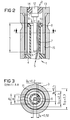
- the socket plug part 1 shows in FIGS. 1 and 2 short piece of the bracing against the outer conductor 3 Isolierstoff Sciences 4, in which the plug-side inner conductor 5 is supported. At least the part of the inner conductor 5 that extends within the socket plug part 1 is one Leaf spring 6.
- the leaf spring 6 is located in an insulating tube 7, which is arranged concentrically to the outer conductor 3, finger-like protruding into the socket plug part Pipe approach of the insulating body 4 is.
- the insulating tube 7 has an annular flange 8 at its free end and is here in its tube opening 9 in the form of a pre-centering funnel 10 expanded.
- the pre-centering funnel 10 serves to pre-center the its free end designed as a plug pin 11 inner conductor 12 of the male connector part 2.
- the outer conductor 13 of the pin plug part 2 goes in the area of its pin connector part 2 a spring bushing 15 which, as can be seen in FIG. 2, when the plug and mating connector are connected a spring contact with the inner wall of the outer conductor 3 of the connector in the area of its socket connector part 1.
- the tube opening 16 of the outer conductor 3 is at his free end expanded, also in the form of a pre-centering funnel 17 for the spring bushing at its free end 15 designed outer conductor 3 of the pin plug part 2.
- the inner conductor 5 in the area of the socket plug part 1 leaf spring 6 has a slightly S-shaped curvature with two centers of curvature 18 and 19.
- the mutual Distance a between the two centers of curvature 18 and 19 of the leaf spring 6 is approximately equal to half the insertion depth s of the connector pin 11 in the insulating tube 7 in the manufactured State of the plug connection.
- the leaf spring 6 also projects its free end via the precentering funnel 10 of the insulating tube 7 outwards. Is located starting from its free end, its first center of curvature 18 still within the insulating tube 7, namely below the pre-centering funnel 10.
- the leaf spring can be dimensioned as provided here without impairing its mechanical stability.
- a value of ⁇ 0.7 and thus a characteristic impedance Z L of> 70 O is achieved.
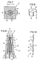
- FIGS. 4 to 10 show two further exemplary embodiments the invention. Those corresponding to the first embodiment Features are provided with the same reference symbols.
- the embodiment shown in Fig. 4 for an angle connector WS has a conductive housing 21 attached to its Front 22 in the outer conductor 3 of the socket plug part 1 transforms.
- the resilient plug socket of the socket plug part 1 consists of an insulating tube 7 with a S-shaped curved leaf spring 6 on the sides the female connector part 1, the free end of the one-piece Inner conductor 5 is.
- the inner conductor 5 is over its entire The length is in the form of a band, so it is a stamped sheet metal part
- the insulating material tube 7 is a finger-like tube attachment of the insulating body 4, the inner tube diameter D2 is equal to the inner diameter D1 of the insulating tube 7.
- the insulating body 4 including the insulating tube 7 is in the extension of the socket plug part 1 in the housing 21 arranged.
- the housing 21 has a cover on its rear side 24 closable opening 25 for the assembly of the angled, a horizontal angle arm 26 and a vertical one Angled arm 27 having inner conductor 5.
- the inner conductor 5 is in the region of its horizontal angle arm 26 in the insulating body 4 and in the area of its vertical angle arm 27 held in an additional insulating support 28.
- the Insulating material support 28 is on the underside 29 of the Housing 21, which directly adjoins the rear side 23 thereof, inserted into the housing 21.
- At its free end is the vertical angle arm 27 of the inner conductor 5 as a pin-shaped Soldering foot 30 designed.
- the underside 29 has on the edge side their circumference evenly distributed four pin-shaped solder feet 31, which are each provided with an offset 32.
- the cross-sectional width B1 the curved leaf spring 6, which is the free end of the horizontal Angular arm 26 of the inner conductor 5 forms is approximately two thirds of the inner diameter D1 of the insulating tube 7.
- the section of the horizontal angle arm 26 of the inner conductor 5, which is located inside the insulating body 4, is B2 in its cross-sectional width at its pipe inside diameter D2 adjusted and points opposite to each other Sides each have a locking hook 33. With With the help of this locking hook 33 is the inner conductor 5, as well the section shown in Fig. 6 and shown in Fig. 4 AA clarifies with its horizontal angle arm 26 in the insulating body 4 fixed or anchored.
- this line section 34 In the transition area between the horizontal angle arm 26 of the Inner conductor 5 and its vertical angle arm 27 forms the Inner conductor 5 together with the housing 21 an insulating material-free Line section 34.
- this line section 34 to the other coaxial line sections of the angled connector WS has the inner conductor 5 an enlarged cross-sectional width in the transition area mentioned B3.
- For fixing or anchoring the inner conductor 5 with its vertical angle arm 27 in the insulating support 28 has the vertical angle arm 27 in the area this insulating support 28 also on opposite one another Sides each have a locking hook 33.
- the insulating material support 23 shown in FIG. 8 also has their rectangular center channel 35 for the engagement of the inner conductor 5 with its vertical angle arm 27 on its circumference Pointed outer webs 36 parallel to the axis.
- the outer webs 36 are the insulating material support 23, like the one in FIG. 7 shown in Fig. 4 section CC still recognize lets in the associated opening in the bottom 29th of the housing 21 held in the press fit.
- the embodiment shown in Fig. 9 in longitudinal section for a straight connector GS differs from Angular connector WS in Fig. 4 actually only in that the Bottom side 37 of its housing 38 here its front side 39 is opposite.
- the band-shaped inner conductor 5 is here, apart from the S-shaped curved spring 6, on his a free end on the part of the female connector part 1, a straight inner conductor 5, whose other free end, that emerges from the housing 38 on the underside 37, and parallel to the soldering feet provided on the housing 31 with offset 32, also a pin-shaped soldering foot 30 is.
- the inner conductor 5 of the straight connector shown in FIG. 10 GS in FIG. 9 has the same extension as the inner conductor 5 corresponding to FIGS. 4 and 5 several sections different Cross-sectional width.
- the one through the S-shaped curved band spring 6 given section again has the Cross-sectional width B1 and that within the insulating body 4 running section again the cross-sectional width B2 attached to the inner tube diameter D2 of the insulating body 4 is adjusted.
- the housing 38 also takes the insulating body here 4 including its insulating tube 7 with the band-shaped inner conductor 5 held here Formation of a non-insulating line section 40 in itself on, which adjoins the underside 37 of the housing 38.
- the inner conductor 5 has wave impedance matching this line section 40 to the rest coaxial line sections an enlarged cross-sectional width B3.
- the pipe inside diameter is D2 of the insulating body 4 is equal to the inner diameter D1 of the Insulating tube 7.
- the cross-sectional width B1 of the S-shaped band spring 6 of the inner conductor 5, which, as already stated, is approximately two thirds of the value of the inner diameter D1 of the insulating tube 7, is due to the fact that the insulating tube 7 when making the plug connection still the plug pin 11 of the mating connector while ensuring adequate Wave resistance adjustment must take in itself.
- the plug can be an angled plug WS according to FIG. 4 or a straight connector GS according to FIG. 9.
Abstract
Description
Die Erfindung bezieht sich auf einen Koaxial-Steckverbinder, bestehend aus einem Stecker mit einem frontseitigen Buchsen-Steckerteil und einem Gegenstecker mit einem frontseitigen Stift-Steckerteil, bei dem beim Stecker und Gegenstecker der Innenleiter im Außenleiter in einem Isolierstoffkörper gehaltert ist und bei dem im vereinigten Zustand des Buchsen-Steckerteils des Steckers mit dem Stift-Steckerteil des Gegensteckers deren freien Innenleiterenden einerseits und deren freien Außenleiterenden andererseits jeweils unter Federspannung kontaktgebend miteinander verbunden sind.The invention relates to a coaxial connector, consisting of a plug with a socket connector on the front and a mating connector with a front Male-male part, in which the plug and mating connector Inner conductor held in the outer conductor in an insulating body is and in the combined state of the socket plug part of the connector with the male-male part of the mating connector their free inner conductor ends on the one hand and their free outer conductor ends, on the other hand, each under spring tension are connected in a contacting manner.
Koaxial-Steckverbinder dieser Art sind beispielsweise durch
die Literaturstelle DE 3701471 C2 bekannt. Hinsichtlich ihrer
Bemessung sind solche Koaxial-Steckverbinder international
durch "Cenelec Electronic Components Committee", kurz CECC
genannt, genormt. Durch CECC 22230 ist für die Steckverbindung
ein Verhältnis 1,0/2,3 von Außenleiterdurchmesser/Innenleiterdurchmesser
festgelegt. In entsprechender Weise ist
durch CECC 22241 für die Steckverbindung ein Verhältnis
1,6/5,6 von Außenleiterdurchmesser/Innenleiterdurchmesser
festgelegt. Wie die Praxis zeigt, ist die Einhaltung dieser
Normen dann nicht mehr möglich, wenn der Steckverbinder für
einen Wellenwiderstand von 75 O zur Übertragung elektromagnetischer
Wellen bei sehr hohen Frequenzen im GHz-Bereich ausgelegt
werden soll. Bezogen auf die Norm CECC 22230 ergibt
sich für den Wellenwiderstand des Steckverbinders nach der
Formel
Der Erfindung liegt die Aufgabe zugrunde, für einen Koaxial-Steckverbinder eine neue konstruktive Lösung anzugeben, die in einfacher Weise auch eine Ausführung mit einem ZL = 75 O unter Einhaltung der oben angegebenen CECC-Norm ermöglicht.The invention has for its object to provide a new constructive solution for a coaxial connector, which also allows a design with a Z L = 75 O in compliance with the above-mentioned CECC standard.
Diese Aufgabe wird für einen Koaxial-Steckverbinder der einleitend beschriebenen Art gemäß der Erfindung dadurch gelöst, daß wenigstens der Teil des Innenleiters des Steckers im Bereich seines Buchsen-Steckerteils eine innerhalb eines zum Außenleiter konzentrisch ausgerichteten Isolierstoffrohres angeordnete Blattfeder ist, die gemeinsam mit dem Isolierstoffrohr dessen federnde Steckerbuchse darstellt, daß das Isolierstoffrohr ein in das Buchsen-Steckerteil des Steckers hineinragender fingerartiger Rohransatz des Isolierstoffkörpers ist, daß die Blattfeder über ihre Länge senkrecht zu ihrer Blattfederebene ein-, zwei- oder mehrfach gekrümmt ist und daß beim Zusammenfügen von Stecker und Gegenstecker der Steckerstift beim Eingreifen in die Rohröffung am freien Ende des Isolierstoffrohres die Blattfeder unter Ausnutzung ihrer gekrümmten Gestaltung gegen die nahe Wandung des Isolierstoffrohres drückt und dabei kontaktgebend spannt.This task is the introductory one for a coaxial connector described type according to the invention solved by that at least the part of the inner conductor of the plug in the area of its socket plug part one within one to Outer conductor of concentrically oriented insulating tube arranged leaf spring is, together with the insulating tube whose resilient plug socket represents that Insulating tube into the female connector part of the connector protruding finger-like pipe neck of the insulating body is that the leaf spring is perpendicular to its length Leaf spring plane is curved one, two or more times and that when the connector and mating connector are joined together Plug pin when reaching into the pipe opening at the free end of the insulating tube using the leaf spring curved design against the close wall of the insulating tube presses and tensions while contacting.
Der Erfindung liegt die wesentliche Erkenntnis zugrunde, daß die federnde Steckerbuchse auf seiten des Steckers für die Innenleiter-Steckverbindung bei einem Koaxial-Steckverbinder auch durch eine den Innenleiter darstellende Blattfeder in einem Isolierstoffrohr realisiert werden kann, in das beim Zusammenfügen von Stecker und Gegenstecker der Steckerstift des Gegensteckers eingeführt wird. Durch die so gestaltete innenleiterseitige federnde Steckerbuchse des Steckers läßt sich in außerordentlich vorteilhafter Weise der wirksame Außendurchmesser dieser Steckerbuchse ohne mechanische Probleme soweit erniedrigen, daß für die Steckverbindung der gewünschte Wellenwiderstand ZL von 75 O realisiert werden kann.The invention is based on the essential finding that the resilient plug socket on the part of the plug for the inner conductor plug connection in a coaxial connector can also be realized by a leaf spring representing the inner conductor in an insulating tube into which the plug pin is joined when the plug and mating plug are joined together of the mating connector is inserted. The spring connector socket of the connector designed in this way on the inner conductor side allows the effective outside diameter of this connector to be reduced in an extremely advantageous manner without mechanical problems to such an extent that the desired characteristic impedance Z L of 75 ° can be achieved for the connector.
Zweckmäßige Ausgestaltungen des Gegenstandes nach dem Patentanspruch 1 sind in den weiteren Patentansprüchen 2 bis 15 angegeben.Appropriate configurations of the subject matter according to the patent claim 1 are specified in the further claims 2 to 15.
Anhand in der Zeichnung dargestellter Ausführungsbeispiele, soll die Erfindung im folgenden noch näher erläutert werden. In der Zeichnung bedeuten
- Fig. 1
- das Buchsen-Steckerteil eines Steckers im Schnitt,
- Fig. 2
- das Buchsen-Steckerteil des Steckers und das Stift-Steckerteil des Gegensteckers im miteinander verbundenen Zustand von Stecker und Gegenstecker im Schnitt,
- Fig. 3
- der Schnitt AA der in Fig. 2 dargestellten Steckverbindung.
- Fig. 4
- ein einen Winkelstecker darstellendes Ausführungsbeispiel im Längsschnitt,
- Fig. 5
- der Innenleiter des Winkelsteckers nach Fig. 4 in perspektivischer Darstellung,
- Fig. 6
- der in Fig. 4 angegebene Schnitt AA des WinkelSteckers,
- Fig. 7
- der in Fig. 4 angegebene Schnitt BB des WinkelSteckers,
- Fig. 8
- das den abgewinkelten Teil des Innenleiters im Gehäuse des Winkelsteckers nach Fig. 4 halternde Isolierstoffteil,
- Fig. 9
- ein einen geraden Stecker darstellendes Ausführungsbeispiel im Längsschnitt,
- Fig. 10
- der Innenleiter des geraden Steckers nach Fig. 9 in perspektivischer Darstellung,
- Fig. 1
- the socket-plug part of a plug in section,
- Fig. 2
- the female connector part of the connector and the male connector part of the mating connector in the interconnected state of the connector and mating connector in section,
- Fig. 3
- the section AA of the connector shown in Fig. 2.
- Fig. 4
- an embodiment of an angled connector in longitudinal section,
- Fig. 5
- 4 in a perspective view,
- Fig. 6
- the section AA of the angled plug shown in FIG. 4,
- Fig. 7
- the section BB of the angled connector shown in FIG. 4,
- Fig. 8
- the insulating part holding the angled part of the inner conductor in the housing of the angled plug according to FIG. 4,
- Fig. 9
- an embodiment of a straight connector in longitudinal section,
- Fig. 10
- 9 is a perspective view of the inner conductor of the straight plug according to FIG. 9,
Bei dem in der Zeichnung in Schnitten dargestellten Ausführungsbeispiel ist aus Gründen der Einfachheit in Fig. 1 vom Stecker lediglich das Buchsen-Steckerteil 1 und in Fig. 2 vom Stecker und vom Gegenstecker lediglich das Buchsen-Steckerteil 1 und das Stift-Steckerteil 2 im ineinandergeschobenen Zustand dargestellt. Entsprechendes gilt hinsichtlich des in Fig. 3 dargestellten Schnitts AA der Fig. 2.In the embodiment shown in the drawing in sections is for simplicity in Fig. 1 from Plug only the socket plug part 1 and in Fig. 2 from Plug and from the mating connector only the female connector part 1 and the male connector part 2 in the nested State shown. The same applies to the in 3 shown section AA of FIG. 2nd
Das Buchsen-Steckerteil 1 zeigt in den Fig. 1 und 2 noch ein
kurzes Stück des sich gegen den Außenleiter 3 abstützenden
Isolierstoffkörpers 4, in dem der steckerseitige Innenleiter
5 gehaltert ist. Wenigstens der Teil des Innenleiters 5, der
sich innerhalb des Buchsen-Steckerteils 1 erstreckt, ist eine
Blattfeder 6. Die Blattfeder 6 befindet sich in einem Isolierstoffrohr
7, das ein konzentrisch zum Außenleiter 3 angeordneter,
in das Buchsen-Steckerteil hineinragender fingerartigen
Rohransatz des Isolierstoffkörpers 4 ist. Das Isolierstoffrohr
7 weist an seinem freien Ende eine Ringflansch 8
auf und ist hier in seiner Rohröffnung 9 in Form eines Vorzentriertrichters
10 erweitert.The socket plug part 1 shows in FIGS. 1 and 2
short piece of the bracing against the
Der Vorzentriertrichter 10 dient der Vorzentrierung des an
seinem freien Ende als Steckerstift 11 gestalteten Innenleiters
12 des Stift-Steckerteils 2. Entsprechend der Ausführung
des Steckers mit dem Buchsen-Steckerteil 1 ist beim Gegenstecker
mit dem Stift-Steckerteil 2 der Innenleiter 12 innerhalb
eines sich gegen dessen Außenleiter 13 abstützenden Isolierstoffkörpers
14 gehaltert. Der Außenleiter 13 des Stift-Steckerteils
2 geht im Bereich seines Stift-Steckerteils 2 in
eine Federbuchse 15 über, die sich, wie Fig. 2 erkennen läßt,
im miteinander verbundenen Zustand von Stecker und Gegenstekker
einen Federkontakt mit der Innenwand des Außenleiters 3
des Steckers im Bereich seines Buchsen-Steckerteils 1 herstellt.
Die Rohröffnung 16 des Außenleiters 3 ist an seinem
freien Ende erweitert, und zwar ebenfalls in Form eines Vorzentriertrichters
17 für den an seinem freien Ende als Federbuchse
15 gestalteten Außenleiter 3 des Stift-Steckerteils 2.The
Die den Innenleiter 5 im Bereich des Buchsen-Steckerteils 1
darstellende Blattfeder 6 weist eine leicht S-förmige Krümmung
mit zwei Krümmungsschwerpunkten 18 und 19 auf. Der gegenseitige
Abstand a der beiden Krümmungsschwerpunkte 18 und
19 der Blattfeder 6 ist etwa gleich der halben Stecktiefe s
des Steckerstifts 11 im Isolierstoffrohr 7 im hergestellten
Zustand der Steckverbindung. Die Blattfeder 6 ragt ferner an
ihrem freien Ende über den Vorzentriertrichter 10 des Isolierstoffrohres
7 hinaus nach außen. Dabei befindet sich,
ausgehend von ihrem freien Ende, ihr erster Krümmungsschwerpunkt
18 noch innerhalb des Isolierstoffrohres 7, und zwar
unterhalb des Vorzentriertrichters 10. Das freie Ende der
Blattfeder 6, das unter einem Winkel a zwischen 30 und 5o°zur
Rohrachse RA aus dem Isolierstoffrohr 7 herausragt, stellt
für den Steckerstift 11 des Stift-Steckerteils 2 eine schräge
Kontaktzunge 20 dar, über die hinweg der Steckerstift 11 beim
Herstellen der Steckverbindung an der Blattfeder 6 angreift
und diese unter Ausnutzung ihrer S-förmigen Krümmung gegen
die nahe Wandung des Isolierstoffrohres 7 drückt und diese
dabei kontaktgebend, wie das Fig. 2 zeigt, spannt.The
Abschließend soll anhand des in Fig. 3 dargestellten Schnitts AA der Fig. 2 noch auf die Bemessung des dargestellten Ausführungsbeispiels für einen Wellenwiderstand ZL der Steckverbindung von 75 O unter Einhaltung der Norm CECC 22230 kurz eingegangen werden.Finally, with reference to the section AA of FIG. 2 shown in FIG. 3, the dimensioning of the exemplary embodiment shown for a characteristic impedance Z L of the plug connection of 75 O in compliance with the standard CECC 22230 will be briefly discussed.
In Fig. 3 sind die durch die Norm vorgegebenen Werte wie
folgt angegeben.
Bei der so vorgegebenen Bemessung der Steckverbindung kann
die Blattfeder ohne eine Beeinträchtigung ihrer mechanischen
Stabilität wie hier vorgesehen bemessen werden.
Damit wird für den wirksamen Durchmesser des Innenleiters der
Steckverbindung ein Wert von ∼ 0,7 und damit ein Wellenwiderstand
ZL von > 70 O erreicht. Die genaue Anpassung der Steckverbindung
an ZL = 75 O wird durch die entsprechende Bemessung
des Isolierstoffrohres 7 hinsichtlich seiner Wandstärke
durch entsprechende Wahl seines Außendurchmessers da und seines
Innendurchmessers di unter Berücksichtigung der Dielektrizitätskonstante
e des verwendeten Isoliermaterials erreicht.For the effective diameter of the inner conductor of the plug connection, a value of ∼ 0.7 and thus a characteristic impedance Z L of> 70 O is achieved. The exact adaptation of the plug connection to Z L = 75 O is achieved by appropriately dimensioning the insulating
Die Figuren 4 bis 10 zeigen zwei weitere Ausführungsbeispiele der Erfindung. Die mit dem ersten Ausführungsbeispiel übereinstimmenden Merkmale sind mit gleichen Bezugszeichen versehen.Figures 4 to 10 show two further exemplary embodiments the invention. Those corresponding to the first embodiment Features are provided with the same reference symbols.
Das in Fig. 4 dargestellte Ausführungsbeispiel für einen Winkelstecker
WS hat ein leitendes Gehäuse 21, das an seiner
Frontseite 22 in den Außenleiter 3 des Buchsen-Steckerteils 1
übergeht. Die federnde Steckerbuchse des Buchsen-Steckerteils
1 besteht aus einem Isolierstoffrohr 7 mit einer hierin angeordneten,
S-förmig gekrümmten Blattfeder 6, die auf seiten
des Buchsen-Steckerteils 1 das freie Ende des einstückigen
Innenleiters 5 ist. Der Innenleiter 5 ist über seine gesamte
Länge bandförmig ausgeführt, stellt also ein Blech-Stanzteil
dar. Das Isolierstoffrohr 7 ist ein fingerartiger Rohransatz
des Isolierstoffkörpers 4, dessen Rohr-Innendurchmesser D2
gleich dem Innendurchmesser D1 des Isolierstoffrohres 7 ist.
Der Isolierstoffkörper 4 einschließlich des Isolierstoffrohres
7 ist in Erstreckung des Buchsen-Steckerteils 1 im Gehäuse
21 angeordnet.The embodiment shown in Fig. 4 for an angle connector
WS has a
Das Gehäuse 21 hat an seiner Rückseite eine mit einer Abdekkung
24 verschließbare Öffnung 25 für die Montage des abgewinkelten,
einen waagrechten Winkelarm 26 und einen senkrechten
Winkelarm 27 aufweisenden Innenleiters 5. Der Innenleiter
5 ist im Bereich seines waagrechten Winkelarms 26 im Isolierstoffkörper
4 und im Bereich seines senkrechten Winkelarms 27
in einer zusätzlichen Isolierstoffstütze 28 gehaltert. Die
Isolierstoffstütze 28 ist hierbei an der Unterseite 29 des
Gehäuses 21, die unmittelbar an dessen Rückseite 23 angrenzt,
in das Gehäuse 21 eingesetzt. An seinem freien Ende ist der
senkrechte Winkelarm 27 des Innenleiters 5 als stiftförmiger
Lötfuß 30 gestaltet. Randseitig weist die Unterseite 29 über
ihren Umfang gleichmäßig verteilt vier stiftförmige Lötfüße
31 auf, die jeweils mit einem Offset 32 versehen sind. Durch
den Offset 32 ergibt sich beim Aufsetzen des Winkelsteckers
WS auf eine Leiterplatte ein kleiner Zwischenraum zwischen
seiner Unterseite 29 und der Leiterplattenoberfläche, die für
ein einwandfreies Verlöten der Lötfüße 31 des Gehäuses 21 und
des Lötfußes 30 des Innenleiters 5 in den ihnen zugeordneten
kontaktierten Montagelöchern in der in den Figuren nicht dargestellten
Leiterplatte erforderlich ist.The
Auf die Gestaltung des bandförmigen abgewinkelten Innenleiters
5 soll nun anhand der Fig. 5 in Verbindung mit der Fig.
4 noch näher eingegangen werden. Die Querschnittsbreite B1
der gekrümmtem Blattfeder 6, die das freie Ende des waagrechten
Winkelarms 26 des Innenleiters 5 bildet, beträgt etwa
zwei Drittel des Innendurchmessers D1 des Isolierstoffrohres
7. Das Teilstück des waagrechten Winkelarms 26 des Innenleiters
5, das sich innerhalb des Isolierstoffkörpers 4 befindet,
ist in seiner Querschnittsbreite B2 an dessen Rohr-Innendurchmessser
D2 angepaßt und weist auf einander gegenüberliegenden
Seiten jeweils einen Sperrhaken 33 auf. Mit
Hilfe dieser Sperrhaken 33 ist der Innenleiter 5, wie auch
der in Fig. 6 dargestellte und in Fig. 4 angegebene Schnitt
AA verdeutlicht, mit seinem waagrechten Winkelarm 26 im Isolierstoffkörper
4 fixiert bzw. verankert.On the design of the ribbon-shaped angled
Im Übergangsbereich zwischen dem waagrechten Winkelarm 26 des
Innenleiters 5 und dessen senkrechten Winkelarm 27 bildet der
Innenleiter 5 zusammen mit dem Gehäuse 21 einen isolierstoffreien
Leitungsabschnitt 34. Zur Wellenwiderstandsanpassung
dieses Leitungsabschnitts 34 an die übrigen koaxialen Leitungsabschnitte
des Winkelsteckers WS hat der Innenleiter 5
in dem genannten Übergangsbereich eine vergrößerte Querschnittsbreite
B3. Für die Fixierung bzw. Verankerung des Innenleiters
5 mit seinem senkrechten Winkelarm 27 in der Isolierstoffstütze
28 weist der senkrechte Winkelarm 27 im Bereich
dieser Isolierstoffstütze 28 ebenfalls auf einander gegenüberliegenden
Seiten jeweils einen Sperrhaken 33 auf.In the transition area between the
Die in Fig. 8 dargestellte Isolierstoffstütze 23 weist neben
ihrem rechteckigen Mittenkanal 35 für den Eingriff des Innenleiters
5 mit seinem senkrechten Winkelarm 27 an ihrem Umfang
achsenparallele spitzkantige Außenstege 36 auf. Mit diesen
Außenstegen 36 ist die Isolierstoffstütze 23, wie der in Fig.
7 dargestellte, in Fig. 4 angegebene Schnitt CC noch erkennen
läßt, in der ihr zugeordneten Öffnung in der Unterseite 29
des Gehäuses 21 im Preßsitz gehaltert.The insulating
Das in Fig. 9 im Längsschnitt dargestellte Ausführungsbeispiel
für einen geraden Stecker GS unterscheidet sich vom
Winkelstecker WS in Fig. 4 eigentlich nur dadurch, daß die
Unterseite 37 seines Gehäuses 38 hier seiner Frontseite 39
gegenüber liegt. Der bandförmige Innenleiter 5 ist hier, abgesehen
von der s-förmig gekrümmten Bandfeder 6, an seinem
einen freien Ende auf seiten des Buchsen-Steckerteils 1, ein
in sich gerader Innenleiter 5 ist, dessen anderes freies Ende,
das an der Unterseite 37 aus dem Gehäuse 38 austritt, und
zwar parallel zu den hier vorgesehenen gehäuseseitigen Lötfüßen
31 mit Offset 32, ebenfalls ein stiftförmiger Lötfuß 30
ist.The embodiment shown in Fig. 9 in longitudinal section
for a straight connector GS differs from
Angular connector WS in Fig. 4 actually only in that the
Bottom side 37 of its housing 38 here its
Der in Fig. 10 dargestellte Innenleiter 5 des geraden Stekkers
GS in Fig. 9 hat in seiner Erstreckung, wie der Innenleiter
5 entsprechend den Fig. 4 und 5 mehrere Abschnitte unterschiedlicher
Querschnittsbreite. Der durch die S-förmig
gekrümmte Bandfeder 6 gegebene Abschnitt hat wiederum die
Querschnittsbreite B1 und der innerhalb des Isolierstoffkörpers
4 verlaufende Abschnitt wiederum die Querschnittsbreite
B2, die an den Rohr-Innendurchmesser D2 des Isolierstoffkörpers
4 angepaßt ist. Das Gehäuse 38 nimmt auch hier den Isolierstoffkörper
4 einschließlich seines Isolierstoffrohres 7
mit dem hierin gehalterten bandförmigen Innenleiter 5 unter
Bildung eines isolierstoffreien Leitungsabschnitts 40 in sich
auf, der hierbei an die Unterseite 37 des Gehäuses 38 angrenzt.
In diesem Abschnitt hat der Innenleiter 5 zur Wellenwiderstandsanpassung
dieses Leitungsabschnittes 40 an die übrigen
koaxialen Leitungsabschnitte eine vergrößerte Querschnittsbreite
B3. Auch hier ist der Rohr-Innendurchmesser D2
des Isolierstoffkörpers 4 gleich dem Innendurchmesser D1 des
Isolierstoffrohres 7.The
Die Querschnittsbreite B1 der S-förmig gekrümmten Bandfeder 6
des Innenleiters 5, die, wie bereits ausgeführt wurde, etwa
zwei Drittel des Wertes des Innendurchmessers D1 des Isolierstoffrohres
7 hat, ist dadurch bedingt, daß das Isolierstoffrohr
7 bei Herstellung der Steckverbindung noch den Steckerstift
11 des Gegensteckers unter Gewährleistung einer ausreichenden
Wellenwiderstandanpassung in sich aufnehmen muß.The cross-sectional width B1 of the S-shaped
Bei der in den Figuren 1 bis 3 dargestellten Steckverbindungen kann der Stecker ein Winkelstecker WS entsprechend Fig. 4 oder ein gerader Stecker GS entsprechend Fig. 9 sein. In the plug connections shown in Figures 1 to 3 the plug can be an angled plug WS according to FIG. 4 or a straight connector GS according to FIG. 9.
- 11
- = Buchsen-Steckerteil= Socket plug part
- 22nd
- = Stift-Steckerteil= Male-male part
- 3, 133, 13
- = Außenleiter= Outer conductor
- 4, 144, 14
- = Isolierstoffkörper= Insulating body
- 5, 125, 12
- = Innenleiter= Inner conductor
- 66
- = Blattfeder= Leaf spring
- 77
- = Isolierstoffrohr= Insulating tube
- 88th
- = Ringflansch= Ring flange
- 9, 169, 16
- = Rohröffnung= Pipe opening
- 10, 1710, 17
- = Vorzentriertrichter= Pre-centering funnel
- 1111
- = Steckerstift= Plug pin
- 1515
- = Federbuchse= Spring bush
- 18, 1918, 19
- = Krümmungsschwerpunkt= Center of curvature
- 2020th
- = Kontaktzunge= Contact tongue
- 21, 3821, 38
- = Gehäuse= Housing
- 22, 3922, 39
- = Frontseite= Front
- 2323
- = Rückseite= Back
- 2424th
- = Abdeckung= Cover
- 2525th
- = Öffnung= Opening
- 26, 2726, 27
- = Winkelarm= Angle arm
- 2828
- = Isolierstoffstütze= Insulation support
- 29, 3729, 37
- = Unterseite= Underside
- 30, 3130, 31
- = Lötfuß= Solder foot
- 3232
- = Offset= Offset
- 3333
- = Sperrhaken= Locking hook
- 34, 4034, 40
- = Leitungsabschnitt= Line section
- 3535
- = Mittenkanal= Center channel
- 3636
- = Außensteg= Outer web
- ZL Z L
- = Wellenwiderstand= Characteristic impedance
- aa
- = Abstand= Distance
- ss
- = Stecktiefe= Insertion depth
- RARA
- = Rohrachse= Pipe axis
- aa
- = Winkel = Angle
- Dib D ib
- = Innendurchmesser Außenleiter SteckerBuchsenteil= Inner diameter outer conductor plug socket part
- Dis D is
- = Innendurchmesser Außenleiter Stift-Steckerteil= Inner diameter outer conductor pin-plug part
- Ds D s
- = Durchmesser Steckerstift= Connector pin diameter
- Qb Q b
- = Querschnittsbreite Blattfeder= Cross-sectional width of leaf spring
- Qh Q h
- = Querschnittshöhe Blattfeder= Cross-sectional height of leaf spring
- di d i
- = Innendurchmesser Isolierstoffrohr= Inner diameter of insulating tube
- da d a
- = Außendurchmesser Isolierstoffrohr= Outer diameter of insulating tube
- Ds D s
- = Durchmesser Steckerstift= Connector pin diameter
- WSWS
- = Winkelstecker= Angle plug
- GSGS
- = gerader Stecker= straight plug
- D1D1
- = Innendurchmesser= Inside diameter
- D2D2
- = Rohr-Innendurchmesser= Inner tube diameter
Claims (15)
dadurch gekennzeichnet, daß
die Rohröffnung (9) am freien Ende des Isolierstoffrohrs (7) erweitert ist, und zwar zu einem Vorzentriertrichter (10) für den Steckerstift (11) des Gegensteckers.Coaxial connector according to claim 1,
characterized in that
the tube opening (9) at the free end of the insulating tube (7) is widened to a precentering funnel (10) for the plug pin (11) of the mating connector.
dadurch gekennzeichnet, daß
die Blattfeder (6) mit ihrem freien Ende über den Vorzentriertrichter (10) des Isolierrohres (7) hinaus unter einem solchen Winkel (a) zur Rohrachse (RA) des Isolierstoffrohres (7) nach außen übersteht, daß sie dem Steckerstift (11) beim Zusammenfügen von Stecker und Gegenstecker für ihr Spannen gegen die Innenwandung des Isolierstoffrohres (7) an diesem ihrem freien Ende eine schräge Kontaktzunge (20) bietet, die den Steckvorgang leicht und sicher gestaltet.Coaxial connector according to claim 1 or 2,
characterized in that
the leaf spring (6) with its free end over the pre-centering funnel (10) of the insulating tube (7) at such an angle (a) to the tube axis (RA) of the insulating tube (7) that it protrudes from the connector pin (11) Joining the plug and mating connector for their tensioning against the inner wall of the insulating tube (7) at this free end provides an oblique contact tongue (20), which makes the plugging process easy and safe.
dadurch gekennzeichnet, daß
die Blattfeder (6) an ihrem freien Ende eine leicht S-förmige Krümmung mit zwei Krümmungsschwerpunkten (18, 19) aufweist, deren Länge in erster Näherung gleich der Stecktiefe (s) des Steckerstiftes (11) im Isolierstoffrohr (7) im zusammengefügten Zustand von Stecker und Gegenstecker ist.Coaxial connector according to one of the preceding claims,
characterized in that
the leaf spring (6) has at its free end a slightly S-shaped curvature with two centers of curvature (18, 19), the length of which, in a first approximation, is equal to the insertion depth (s) of the plug pin (11) in the insulating tube (7) in the assembled state of Plug and mating connector is.
dadurch gekennzeichnet, daß
characterized in that
dadurch gekennzeichnet, daß
characterized in that
dadurch gekennzeichnet, daß
das Isolierstoffrohr (7) des Steckers an seinem freien Ende mit einem Ringflansch (8) versehen ist.Coaxial connector according to one of the preceding claims,
characterized in that
the insulating tube (7) of the plug is provided with an annular flange (8) at its free end.
gekennzeichnet durch
seine Bemessung für einen Wellenwiderstand von 75 O unter Einhaltung der Dimensionierung entsprechend Normung nach CECC 22230 für "RADIO FREQUENCY COAXIAL CONNECTORS Series 1,0/2,3" bzw. CECC 22241 "RADIO FREQUENCY COAXIAL CONNECTORS Series 1,6 /5,6".Coaxial connector according to one of the preceding claims,
marked by
its dimensioning for a characteristic impedance of 75 O while observing the dimensioning in accordance with standardization according to CECC 22230 for "RADIO FREQUENCY COAXIAL CONNECTORS Series 1.0 / 2.3" or CECC 22241 "RADIO FREQUENCY COAXIAL CONNECTORS Series 1.6 / 5.6" .
dadurch gekennzeichnet, daß
characterized in that
gekennzeichnet durch
marked by
dadurch gekennzeichnet, daß
characterized in that
gekennzeichnet durch
marked by
dadurch gekennzeichnet, daß
characterized in that
dadurch gekennzeichnet, daß
der bandförmige Innenleiter (5) an seinem eine gekrümmte Blattfeder (6) darstellenden freien Ende auf seiten des Buchsen-Steckerteils (1) mit einer Oberflächenveredelung, z.B. in Form einer Goldauflage, versehen ist.Coaxial connector according to one of the preceding claims,
characterized in that
the band-shaped inner conductor (5) is provided on its free end, which is a curved leaf spring (6), on the side of the socket connector part (1) with a surface finish, for example in the form of a gold plating.
dadurch gekennzeichnet, daß
der Innendurchmesser (D1, di) des einen fingerartigen Rohransatz des Isolierstoffkörpers (4) darstellenden Isolierstoffrohres (7) und der Rohr-Innendurchmesser (D2) des Isolierstoffkörpers (4) gleich groß sind.Coaxial connector according to one of the preceding claims,
characterized in that
the inside diameter (D1, d i ) of the insulating tube (7), which represents a finger-like tube extension of the insulating body (4), and the inside diameter of the tube (D2) of the insulating body (4) are the same size.
Applications Claiming Priority (4)
| Application Number | Priority Date | Filing Date | Title |
|---|---|---|---|
| DE19810799 | 1998-03-12 | ||
| DE19810799 | 1998-03-12 | ||
| DE19815627 | 1998-04-07 | ||
| DE19815627 | 1998-04-07 |
Publications (3)
| Publication Number | Publication Date |
|---|---|
| EP0942496A2 true EP0942496A2 (en) | 1999-09-15 |
| EP0942496A3 EP0942496A3 (en) | 2001-08-01 |
| EP0942496B1 EP0942496B1 (en) | 2004-06-16 |
Family
ID=26044581
Family Applications (1)
| Application Number | Title | Priority Date | Filing Date |
|---|---|---|---|
| EP99104965A Expired - Lifetime EP0942496B1 (en) | 1998-03-12 | 1999-03-12 | Coaxial connector |
Country Status (3)
| Country | Link |
|---|---|
| EP (1) | EP0942496B1 (en) |
| AT (1) | ATE269593T1 (en) |
| DE (1) | DE59909711D1 (en) |
Citations (5)
| Publication number | Priority date | Publication date | Assignee | Title |
|---|---|---|---|---|
| DE3341356A1 (en) * | 1983-11-15 | 1985-05-23 | Kathrein-Werke Kg, 8200 Rosenheim | Coaxial-cable connecting device |
| US4633048A (en) * | 1984-12-30 | 1986-12-30 | Hosiden Electronics Co., Ltd. | Jack with a switch |
| EP0279359A1 (en) * | 1987-02-12 | 1988-08-24 | Hosiden Corporation | Pin jack with an optical element holder |
| US5267871A (en) * | 1992-07-02 | 1993-12-07 | The Whitaker Corporation | Switching electrical connector |
| US5413502A (en) * | 1994-02-01 | 1995-05-09 | Wang; Tsan-Chi | Auto termination type electrical connector |
-
1999
- 1999-03-12 DE DE59909711T patent/DE59909711D1/en not_active Expired - Fee Related
- 1999-03-12 EP EP99104965A patent/EP0942496B1/en not_active Expired - Lifetime
- 1999-03-12 AT AT99104965T patent/ATE269593T1/en not_active IP Right Cessation
Patent Citations (5)
| Publication number | Priority date | Publication date | Assignee | Title |
|---|---|---|---|---|
| DE3341356A1 (en) * | 1983-11-15 | 1985-05-23 | Kathrein-Werke Kg, 8200 Rosenheim | Coaxial-cable connecting device |
| US4633048A (en) * | 1984-12-30 | 1986-12-30 | Hosiden Electronics Co., Ltd. | Jack with a switch |
| EP0279359A1 (en) * | 1987-02-12 | 1988-08-24 | Hosiden Corporation | Pin jack with an optical element holder |
| US5267871A (en) * | 1992-07-02 | 1993-12-07 | The Whitaker Corporation | Switching electrical connector |
| US5413502A (en) * | 1994-02-01 | 1995-05-09 | Wang; Tsan-Chi | Auto termination type electrical connector |
Also Published As
| Publication number | Publication date |
|---|---|
| ATE269593T1 (en) | 2004-07-15 |
| EP0942496B1 (en) | 2004-06-16 |
| DE59909711D1 (en) | 2004-07-22 |
| EP0942496A3 (en) | 2001-08-01 |
Similar Documents
| Publication | Publication Date | Title |
|---|---|---|
| DE69421798T2 (en) | Modular Jack connector | |
| DE60104328T2 (en) | COAXIAL CONNECTOR | |
| DE69826608T2 (en) | Coax connector | |
| DE60131793T2 (en) | antenna device | |
| DE60036250T2 (en) | Modular jack connector with filter cartridge and contact for it | |
| DE2404669A1 (en) | ELECTRIC PLUG | |
| EP0921609A2 (en) | Right angled HF coaxial connector | |
| EP3635814A1 (en) | Dual-polarised crossed dipole and antenna arrangement having two such dual-polarised crossed dipoles | |
| EP1671401A1 (en) | Coaxial plug-and-socket connector | |
| EP0867978A2 (en) | Angled coaxial connector | |
| DE60118268T2 (en) | Substrate mount connector | |
| DE2806616A1 (en) | ELECTRIC SOCKET CONNECTOR FOR PRINTED CIRCUIT PANELS | |
| EP0924809B1 (en) | High frequency right angle coaxial connector device | |
| DE19724581A1 (en) | Socket for printed circuit boards | |
| EP0942496B1 (en) | Coaxial connector | |
| DE10104863A1 (en) | Planar antenna | |
| EP2093838A1 (en) | Yagi Antenna | |
| DE4132214C2 (en) | Terminal block especially for printed circuit boards | |
| EP0725987B1 (en) | Filter plug connector with screened casing | |
| EP0772253A1 (en) | Angled connector | |
| DE19851790C2 (en) | coaxial | |
| DE602005003682T2 (en) | antenna unit | |
| WO2000046882A1 (en) | Hf right-angle coaxial connector element | |
| WO2006092280A9 (en) | Electronic device for a vehicle, especially an antenna amplifier or a tv tuner, comprising a receiving space for a plug-in connector | |
| EP0290827A2 (en) | Electrical connector for printed circuit boards |
Legal Events
| Date | Code | Title | Description |
|---|---|---|---|
| PUAI | Public reference made under article 153(3) epc to a published international application that has entered the european phase |
Free format text: ORIGINAL CODE: 0009012 |
|
| AK | Designated contracting states |
Kind code of ref document: A2 Designated state(s): AT BE CH DE FR GB IT LI NL SE |
|
| AX | Request for extension of the european patent |
Free format text: AL;LT;LV;MK;RO;SI |
|
| PUAL | Search report despatched |
Free format text: ORIGINAL CODE: 0009013 |
|
| AK | Designated contracting states |
Kind code of ref document: A3 Designated state(s): AT BE CH CY DE DK ES FI FR GB GR IE IT LI LU MC NL PT SE |
|
| AX | Request for extension of the european patent |
Free format text: AL;LT;LV;MK;RO;SI |
|
| RAP1 | Party data changed (applicant data changed or rights of an application transferred) |
Owner name: TYCO ELECTRONICS LOGISTICS AG |
|
| 17P | Request for examination filed |
Effective date: 20020121 |
|
| AKX | Designation fees paid |
Free format text: AT BE CH DE DK ES FI FR GB LI |
|
| RBV | Designated contracting states (corrected) |
Designated state(s): AT BE CH DE FR GB IT LI NL SE |
|
| 17Q | First examination report despatched |
Effective date: 20030627 |
|
| GRAP | Despatch of communication of intention to grant a patent |
Free format text: ORIGINAL CODE: EPIDOSNIGR1 |
|
| RIC1 | Information provided on ipc code assigned before grant |
Ipc: 7H 01R 13/646 A |
|
| RIC1 | Information provided on ipc code assigned before grant |
Ipc: 7H 01R 13/646 A |
|
| GRAS | Grant fee paid |
Free format text: ORIGINAL CODE: EPIDOSNIGR3 |
|
| GRAA | (expected) grant |
Free format text: ORIGINAL CODE: 0009210 |
|
| AK | Designated contracting states |
Kind code of ref document: B1 Designated state(s): AT BE CH DE FR GB IT LI NL SE |
|
| PG25 | Lapsed in a contracting state [announced via postgrant information from national office to epo] |
Ref country code: NL Free format text: LAPSE BECAUSE OF FAILURE TO SUBMIT A TRANSLATION OF THE DESCRIPTION OR TO PAY THE FEE WITHIN THE PRESCRIBED TIME-LIMIT Effective date: 20040616 Ref country code: FR Free format text: LAPSE BECAUSE OF NON-PAYMENT OF DUE FEES Effective date: 20040616 |
|
| REG | Reference to a national code |
Ref country code: GB Ref legal event code: FG4D Free format text: NOT ENGLISH |
|
| REG | Reference to a national code |
Ref country code: CH Ref legal event code: EP |
|
| REG | Reference to a national code |
Ref country code: CH Ref legal event code: NV Representative=s name: RITSCHER & PARTNER AG |
|
| REF | Corresponds to: |
Ref document number: 59909711 Country of ref document: DE Date of ref document: 20040722 Kind code of ref document: P |
|
| PG25 | Lapsed in a contracting state [announced via postgrant information from national office to epo] |
Ref country code: SE Free format text: LAPSE BECAUSE OF FAILURE TO SUBMIT A TRANSLATION OF THE DESCRIPTION OR TO PAY THE FEE WITHIN THE PRESCRIBED TIME-LIMIT Effective date: 20040916 |
|
| GBT | Gb: translation of ep patent filed (gb section 77(6)(a)/1977) |
Effective date: 20040922 |
|
| NLV1 | Nl: lapsed or annulled due to failure to fulfill the requirements of art. 29p and 29m of the patents act | ||
| PG25 | Lapsed in a contracting state [announced via postgrant information from national office to epo] |
Ref country code: AT Free format text: LAPSE BECAUSE OF NON-PAYMENT OF DUE FEES Effective date: 20050312 |
|
| PGFP | Annual fee paid to national office [announced via postgrant information from national office to epo] |
Ref country code: CH Payment date: 20050321 Year of fee payment: 7 |
|
| PG25 | Lapsed in a contracting state [announced via postgrant information from national office to epo] |
Ref country code: BE Free format text: LAPSE BECAUSE OF NON-PAYMENT OF DUE FEES Effective date: 20050331 |
|
| PLBE | No opposition filed within time limit |
Free format text: ORIGINAL CODE: 0009261 |
|
| STAA | Information on the status of an ep patent application or granted ep patent |
Free format text: STATUS: NO OPPOSITION FILED WITHIN TIME LIMIT |
|
| 26N | No opposition filed |
Effective date: 20050317 |
|
| EN | Fr: translation not filed | ||
| BERE | Be: lapsed |
Owner name: *TYCO ELECTRONICS LOGISTICS A.G. Effective date: 20050331 |
|
| PG25 | Lapsed in a contracting state [announced via postgrant information from national office to epo] |
Ref country code: LI Free format text: LAPSE BECAUSE OF NON-PAYMENT OF DUE FEES Effective date: 20060331 Ref country code: CH Free format text: LAPSE BECAUSE OF NON-PAYMENT OF DUE FEES Effective date: 20060331 |
|
| REG | Reference to a national code |
Ref country code: CH Ref legal event code: PL |
|
| BERE | Be: lapsed |
Owner name: *TYCO ELECTRONICS LOGISTICS A.G. Effective date: 20050331 |
|
| PGFP | Annual fee paid to national office [announced via postgrant information from national office to epo] |
Ref country code: IT Payment date: 20090330 Year of fee payment: 11 Ref country code: DE Payment date: 20090327 Year of fee payment: 11 |
|
| PGFP | Annual fee paid to national office [announced via postgrant information from national office to epo] |
Ref country code: GB Payment date: 20090403 Year of fee payment: 11 |
|
| GBPC | Gb: european patent ceased through non-payment of renewal fee |
Effective date: 20100312 |
|
| PG25 | Lapsed in a contracting state [announced via postgrant information from national office to epo] |
Ref country code: DE Free format text: LAPSE BECAUSE OF NON-PAYMENT OF DUE FEES Effective date: 20101001 |
|
| PG25 | Lapsed in a contracting state [announced via postgrant information from national office to epo] |
Ref country code: GB Free format text: LAPSE BECAUSE OF NON-PAYMENT OF DUE FEES Effective date: 20100312 Ref country code: IT Free format text: LAPSE BECAUSE OF NON-PAYMENT OF DUE FEES Effective date: 20100312 |