EP0942486A2 - Glass antenna device for vehicle - Google Patents
Glass antenna device for vehicle Download PDFInfo
- Publication number
- EP0942486A2 EP0942486A2 EP99104554A EP99104554A EP0942486A2 EP 0942486 A2 EP0942486 A2 EP 0942486A2 EP 99104554 A EP99104554 A EP 99104554A EP 99104554 A EP99104554 A EP 99104554A EP 0942486 A2 EP0942486 A2 EP 0942486A2
- Authority
- EP
- European Patent Office
- Prior art keywords
- antenna
- window glass
- glass
- vehicle
- receiver
- Prior art date
- Legal status (The legal status is an assumption and is not a legal conclusion. Google has not performed a legal analysis and makes no representation as to the accuracy of the status listed.)
- Granted
Links
Images


Classifications
-
- H—ELECTRICITY
- H01—ELECTRIC ELEMENTS
- H01Q—ANTENNAS, i.e. RADIO AERIALS
- H01Q1/00—Details of, or arrangements associated with, antennas
- H01Q1/27—Adaptation for use in or on movable bodies
- H01Q1/32—Adaptation for use in or on road or rail vehicles
-
- H—ELECTRICITY
- H01—ELECTRIC ELEMENTS
- H01Q—ANTENNAS, i.e. RADIO AERIALS
- H01Q1/00—Details of, or arrangements associated with, antennas
- H01Q1/12—Supports; Mounting means
- H01Q1/1271—Supports; Mounting means for mounting on windscreens
- H01Q1/1278—Supports; Mounting means for mounting on windscreens in association with heating wires or layers
Landscapes
- Details Of Aerials (AREA)
- Input Circuits Of Receivers And Coupling Of Receivers And Audio Equipment (AREA)
- Fittings On The Vehicle Exterior For Carrying Loads, And Devices For Holding Or Mounting Articles (AREA)
Abstract
Description
- The present invention relates generally to a glass antenna device for use on vehicles having a rear window in a hinged rear hatch or a hatchback which is widely used in recreational vehicles, station wagons and so on. More particularly, this invention relates to a vehicle window glass antenna device having a first antenna arranged in a rear window glass for the reception of FM and TV broadcasts, and a second antenna arranged in a window glass of a fixed side window, such as an opera window or a quarter window, for the reception of AM broadcasts.
- Glass antenna devices including antenna strips provided, together with a plurality of defogging heater elements (forming a defogger), on a rear window glass of a vehicle for the reception of radio waves are known. In the known glass antenna devices, a choke coil is inserted in a power supply line to the heater elements so that the defogging heater elements can be utilized as a receiving antenna. Additionally, the configuration, arrangement and position of the antenna strips are adjusted so that radio waves at a AM broadcast band and a FM broadcast band (as well as a TV broadcast band when the need arises) can be received at high sensitivity.
- Some known vehicle window glass antenna devices for the reception of AM-FM broadcasts include a preamplifier provided between a feed terminal of the antenna strips and an input terminal of the radio set or receiver so as to improve the reception performance.
- However, use of the preamplifier poses a problem that a waveform distortion or a cross modulation distortion is likely to occur during the reception in a strong electric field, and noise mixed in the glass antenna is amplified. To cope with this problem, various improvements have been proposed for the glass antenna devices to obtain a sufficient degree of reception sensitivity without any preamplifier.
- One such proposed improvement is disclosed in Japanese Patent Laid-open Publication No. (HEI) 6-268422, which provides a glass antenna device having a loop-shaped main antenna strip and a feeding point provided on a vehicle rear window glass. Plural returning strips extending toward the center of the main antenna strip are provided in the neighborhood of the both sides of the main antenna strip, with the top ends of the returning strips used as open ends, so as to obtain a sufficient reception sensitivity at an FM broadcast band without using a preamplifier.
- Japanese Patent Laid-open Publication No. (HEI) 7-111412 discloses another improved known vehicle glass antenna device which comprises a defogger composed of a plurality of defogging heater elements of electric conductor provided on a vehicle rear window glass, an antenna conductor arranged in a predetermined pattern in the neighborhood of the defogger so as to form a capacitive coupling together with the defogger, a reactance circuit inserted between the defogger and a DC power source, and a matching circuit inserted between a feeding point of the antenna conductor and a receiver. To receive a broadcast at high sensitivity without using a preamplifier, an anti-resonance point is set to frequencies at the outside of the broadcast band by the stray capacitance of defogger and the reactance circuit, and a resonance point is set between a minimum frequency of the broadcast band and a frequency being a multiple of 1.5 of a highest frequency of the broadcast band by the impedance of matching circuit, the impedance of receiver, and the impedance when viewing the antenna conductor from the matching circuit.
- Still another improved vehicle glass antenna device known from Japanese Patent Laid-open Publication No. (HEI) 8-162826 includes plural heating conductor strips provided on a vehicle rear window glass in the horizontal direction, and plural antenna conductor strips arranged in the horizontal direction. An auxiliary strip is provided close to a conductor strip at the lowest part of the antenna between a lowest antenna strip and an uppermost heating conductor strip arranged in the horizontal direction. A coil or a coil and a capacitor are inserted between the auxiliary strop and the uppermost heating conductor strip. This arrangement can suppress a leakage current to the vehicle body during the reception of an AM or an FM broadcast wave, and also realize an optimum tuning without any restriction onto an antenna pattern for the reception of FM broadcast waves.
- In a vehicle glass antenna device disclosed in Japanese Patent Laid-open Publication No. (HEI) 9-107218, a defogger, an antenna conductor for AM band, and an antenna conductor for FM band are provided on a vehicle rear window glass. The AM antenna conductor is capacitively coupled to the defogger. The AM antenna conductor and the FM antenna conductor are connected by a circuit component including the inductance component, and a low pass filter is inserted between the defogger and a DC power source. This arrangement can eliminate the need for a choke coil and improves the S/N ratio.
- A vehicle glass antenna device proposed by the present assignee by way of Japanese Patent Laid-open Publication No. (HEI) 9-18222 includes an exclusive antenna and a compatible antenna (defogging heater conductor) formed on a window glass. A transformer has a primary winding connected at its one end to the exclusive antenna and at its middle point to the compatible antenna, and a secondary winding connected to a feeder cable to perform the impedance conversion. With this arrangement, a choke coil is no longer needed, the capacity of the feeder cable is reduced when viewed from the antennas, and the transmission loss is also reduced to such an extent that a practically sufficient reception sensitivity can be obtained.
- Somewhat different vehicle glass antenna devices disclosed in, for example, Japanese Patent Laid-open Publications Nos. (HEI) 2-39702, 6-224611 and 6-224612 have an antenna strip for the reception of FM broadcast waves and another antenna strip for the reception of AM broadcast waves, both antenna strips being provided on a vehicle side window glass.
- It appears clear from the foregoing description that for the reception of an AM broadcast at high sensitivity without use of a preamplifier, an AM broadcast receiving antenna formed on a vehicle rear window glass requires a choke coil or a low pass filter inserted in a feed path or line to a defogging heater or defogger which is used in combination with a matching circuit or an impedance conversion transformer inserted between an antenna strip and a feeding point, or with a circuit including an inductance component or a capacitor between the antenna strip and the defogger or between the antenna strip and an auxiliary strip. Thus, a space must be provided in the vicinity of the rear window glass or on a surface of the rear window glass for the installation of the circuit including the choke coil, inductance component, capacitor and so on.
- However, some types of vehicle, due to a structure peculiar thereto, are sometimes unable to provide a sufficient space available for installation of the circuit components. Particularly, most vehicles having a hinged rear hatch (hereinafter referred to, for brevity, as "hatchback vehicles") have an insufficient circuit-components installation space.
- The hatchback vehicles further require the circuit to have circuit components and a packing structure which are strong enough to withstand shock or impact force produced when the hatchback is opened and closed. This requirement renders the packaging process uneasy to achieve and induces additional cost.
- Furthermore, for the antenna formed on the rear window glass for the reception of AM broadcasts, noises generated from various electric equipments such as a rear wiper, rear lamps and indicators are likely to be mixed in, and an appropriate countermeasure to the noises is in many cases difficult to taken.
- In the case where an antenna conductor for AM band and an antenna conductor for FM band are provided on a vehicle rear window glass, separate adjustment of the reception characteristics of the respective antenna conductors is difficult to achieve. This problem may be overcome by arranging the FM antenna conductor in a vehicle side window glass rather than in the rear window glass. In this instance, there still remains a problem that noises generated from the electric equipments are mixed in the AM antenna arranged in the rear window glass.
- It is accordingly an object of the present invention to provide a glass antenna device for a vehicle, which includes an antenna for AM band (i.e., a medium-wave band receiving antenna) provided on a fixed side window glass of the vehicle so that interference with noise generated from electric equipments of the vehicle can be suppressed and also the need for various electric circuit components conventionally disposed on or in the vicinity of a vehicle rear window glass can be eliminated.
- According to the present invention, there is provided a glass antenna device for use with window glasses of a vehicle, comprising: a defogging heater provided on a rear window glass of the vehicle for defogging the rear window glass; a first receiving antenna provided on the rear window glass for the reception of radio waves in a frequency range above a shortwave band; and a second receiving antenna provided on a fixed side window glass of the vehicle for the reception of radio waves at a medium wave band, the fixed side window glass being located at a different position from the rear window glass.
- The first antenna provided on the rear window glass may include an FM antenna for the reception of FM broadcasts, and the second antenna provided on the fixed side window glass may be an AM antenna for the reception of AM broadcasts. The fixed side window glass may include a window panel of an opera window or of a fixed rear quarter window.
- In the glass antenna device of the present invention, because the FM antenna (receiving antenna for shortwave band) and the AM antenna (receiving antenna for medium wave band) are provided on the rear window glass and the fixed side window glass, respectively, it becomes possible to hold the AM antenna relatively distant from a wire harness connected to electrical equipments, such as a rear wiper, rear lamps and indicators. This arrangement can suppress interference with noise generated from the electric equipments.
- Since the AM antenna is provided on the fixed side window glass other than the rear window glass, the rear window glass has enough room for installation of an FM exclusive antenna, an FM antenna for a frequency range above the shortwave band, a TV antenna, or an antenna for mobile operation. By virtue of a relatively large area provided in the rear window glass, an antenna-pattern design work and an adjustment of frequency response of the antenna can be achieved with ease. Additionally, since the defogging heater is not used as a part of the antenna, no choke coil is required.
- In the case of a conventional glass antenna device having a defogger, an antenna for FM broadcast band and an antenna for AM broadcast band all provided on a rear window glass, an antenna component such as a matching circuit composed of a choke coil, an inductance component, a capacitor and so on must be provided in the vicinity of the rear window glass so as to obtain a sufficient reception level without use of a preamplifier. By contrast, according to the glass antenna device of the present invention, since the rear window glass is used exclusively for installation of an FM exclusive antenna or an antenna other than the AM antenna, the antenna component disposed in the vicinity of the rear window glass is not needed any more.
- In the glass antenna device of the present invention, a signal received at the AM antenna is transmitted through a transformer to a receiver. Use of the transformer insures the reception of AM signal at high sensitivity even though the fixed side window glass, such as a window panel of an opera window or of a fixed rear quarter window, can provide only a small area available for installation of the AM antenna. In other words, the smaller the area of the fixed side window glass, the shorter the length of the AM antenna pattern. However, since transmitting the signal received at the AM antenna through the transformer to the receiver can compensate for a reduction in the reception sensitivity of the AM antenna, the AM antenna can receive AM broadcasts at high sensitivity without any filter circuit to remove noise generated from the electric equipments.
- In the glass antenna device of the present invention, a coaxial cable connected to the FM antenna is connected to the receiver via an AM signal leakage preventing capacitor. The AM signal received at the AM antenna is prevented from passing around into the FM antenna, so that the receiver can receive the FM reception signal at high sensitivity.
- The glass antenna device further includes an AM-antenna-side impedance converter connected to the FM antenna and the AM antenna through respective transmission lines for performing the impedance conversion of the transmission lines, and a receiver-side impedance converter electrically connected to the AM-antenna-side impedance converter, and a receiver connected by a cable to the receiver-side impedance converter. The cable has a distributed capacitance below 10 pF. With this arrangement, the glass antenna device can receive AM broadcasts at high sensitivity with little attenuation of AM reception signals.
- Certain preferred embodiments of the present invention will hereinafter be described in detail, by way of example only, with reference to the accompanying drawings, in which:
- FIG. 1 is a diagrammatical view showing the general arrangement of a glass antenna device for a vehicle having a relatively large side window glass;
- FIG. 2 is a view similar to FIG. 1, but showing a vehicle glass antenna device according to another embodiment in which the vehicle has a relatively small side window glass;
- FIG. 3 is a circuit diagram showing an equivalent circuit of the AM stage of the glass antenna device shown in FIG. 2;
- FIG. 4 is a diagrammatical view showing the pattern of an AM antenna arranged in a vehicle side window glass;
- FIG. 5 is a diagrammatical view showing the pattern of an FM antenna and a defogging heater element arranged in a vehicle rear window glass;
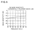
- FIG. 6 is a graph showing the frequency response of the FM band sensitivity of the glass antenna device;
- FIG. 7 is a graph showing the relationship between the AM reception sensitivity and the distributed capacitance of a third coaxial cable;
- FIG. 8 is a diagrammatical view showing the general arrangement of a vehicle glass antenna device according to still another embodiment in which two coaxial cables are used exclusively for an FM antenna and an AM antenna, respectively; and
- FIG. 9 is a diagrammatical view showing the general arrangement of a vehicle glass antenna device according to yet another embodiment in which an AM antenna is arranged in right and left side window glasses.
-
- The following description is merely exemplary in nature and is in no way intended to limit the invention or its application or uses.
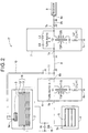
- Referring now to FIG. 1, there is shown a
glass antenna device 1 for a vehicle according to a first embodiment of the present invention. Theglass antenna device 1 includes anAM antenna 18 having a relatively wide antenna pattern which enables the reception of AM broadcasts at high sensitivity. - The vehicle
glass antenna device 1 generally comprises aFM antenna 2 provided on arear window glass 3 of the vehicle for the reception of radio waves in a frequency band above a short-wave band, anAM antenna 18 provided on a fixed window glass, such as aside window glass 4, at a different position from therear window glass 2 for the reception of radio waves in a medium-wave band, areceiver 8, acoaxial cable 10 connected at one end to afeeding point 3a of theFM antenna 3, an FMantenna connection capacitor 11 connected at the other end of thecoaxial cable 10 for connection of theFM antenna 3 to thereceiver 8, a choke coil L4 connected between afeeding point 18a of theAM antenna 18 and thecapacitor 11, and a similarcoaxial cable 9 connected at one end to the junction between thecapacitor 11 and the choke coil L4 and at the other end to thereceiver 8. - The
rear window glass 2 is provided with adefogger 14 composed of a plurality ofdefogging heater elements 12 and a pair of bus bars 13. - When a defogger switch (not shown) is turned on, an electric current from a
battery power source 15 is supplied through the bus bars 13 to theheater elements 12. Acapacitor 16 for absorbing high-frequency noise is connected in parallel with thebattery power source 15 so that high-frequency noises, such as engine ignition noise, are prevented from being mixed into the defogger side. - The choke coil L4 connected to a pattern extending from the
feeding point 18a of theAM antenna 18 and thereceiver 8 are connected together by means of thecoaxial cable 9. The choke coil L4 has an inductance of the order of 2 microhenry (µH) so as to prevent an FM signal from passing from theFM antenna 3 side into theAM antenna 18 side. Thecoaxial cable 9 used in the illustrated embodiment is a 1.5C2V coaxial cable stipulated by Japanese Industrial Standards (JIS), the coaxial cable being hereinafter referred to as JIS1.5C2V coaxial cable. - The choke coil L4 and the
feeding point 3a of theFM antenna 3 are connected together through thecoaxial cable 10 and thecapacitor 11. Thecoaxial cable 10 is also a JIS 1.5C2V coaxial cable. The distance between thefeeding point 3a of theFM antenna 3 and the choke coil L4 is set to be about 2 meters. - The choke coil L4 and a center conductor of the
coaxial cable 10 are connected together via thecapacitor 11. Thecapacitor 11 serves to prevent reduction of the sensitivity (a drop in the reception signal level in the AM broadcast band) which would otherwise occur due to the distributing capacitance of thecoaxial cable 10. Thecapacitor 11 used in the illustrated embodiment has a capacitance of about 56 picofarad (pF). - A reception signal at an FM broadcast band, which is received at the
FM antenna 3 provided on therear window glass 2, is supplied to aninput terminal 8a of thereceiver 8 successively through thefeed pint 3a, thecoaxial cable 10, thecapacitor 11 and thecoaxial cable 9. - A reception signal at an AM broadcast band, which is received at the
AM antenna 18 provided on the fixedside window glass 4, is supplied to theinput terminal 8a of thereceiver 8 successively through thefeeding point 18a, the choke coil L4 and thecoaxial cable 9. - FIG. 2 shows a vehicle
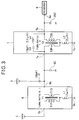
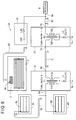
glass antenna device 17 according to a second embodiment of the present invention. Thisantenna device 17 is particularly suitable for an application where a fixedside window glass 4 is relatively small in size and, hence, high AM reception sensitivity is not expected due to a limited area available for arrangement of the antenna pattern of anAM antenna 5. The vehicleglass antenna device 17 differs from the vehicleglass antenna device 1 of the first embodiment shown in FIG. 1 in that it further includes a first impedance conversion circuit or converter (transformer) 6 provided between thefeeding point 5a of theAM antenna 5 and a firstcoaxial cable 9, and a second impedance conversion circuit or converter (transformer) 7 provided between thecoaxial cable 9 an thereceiver 8. The first andsecond impedance converters - The
feeding point 5a of theAM antenna 5 is connected to aninput terminal 6a of the AM-antenna-side impedance converter 6. - The AM-antenna-
side impedance converter 6 includes a transformer T1 for transmitting reception signals at AM broadcast band, and a choke coil L1 that presents a high impedance to frequencies in the FM broadcast band to compensate for or offset a reduction in the FM reception sensitivity resulting from distributed capacitances of the transformer T1 and the secondcoaxial cable 10. - The transformer T1 used in the illustrated embodiment includes a primary winding T1P and a secondary winding T2S which are wound to provide a turn ratio of 9:1. The primary winding T1P has one end connected to an
input terminal 6a of the AM-antenna-side impedance converter 6. One end of the secondary winding T1S is connected to anoutput terminal 6b of the AM-antenna-side impedance converter 6. The other end of the primary winding T1P and the other end of the secondary winding T1S are connected in common to aground terminal 6c through the choke coil L1. The choke coil L1 used in the illustrated embodiment has an inductance of the order of 2 microhenry (2µH). Theground terminal 6c is connected to, for example, a body earth of the vehicle. - A transformer T2 of the receiver-
side impedance converter 7 is the same in construction as the transformer T1 of the AM-antenna-side impedance transformer 6, but the transformer T2 is connected in reverse to the transformer T1 such that the turn ratio of the transformer T2 (the ratio of the number of turns in a primary winding T2P to that in a secondary winding T2S) is 1:9. - The
output terminal 6b of the AM-antenna-side impedance converter 6 (from which the reception signal from theAM antenna 5 is output) and thefeeding point 3a of theFM antenna 3 are connected together by the secondcoaxial cable 10 and the FMantenna connection capacitor 11. Use of the secondcoaxial cable 10 enables the FM reception signal from theFM antenna 3 to be transmitted to thereceiver 8 without attenuation. The secondcoaxial cable 10 used in the illustrated embodiment is a JIS 1.5C2V coaxial cable. The length of thecoaxial cable 10 which extends between thefeeding point 3a of theFM antenna 3 and theoutput terminal 6b of the AM-antenna-side impedance converter 6 is approximately 2 meters (2 m). The center conductor of the secondcoaxial cable 10 and theoutput terminal 6b of the AM-antenna-side impedance converter 6 are interconnected via thecapacitor 11. Thecapacitor 11 serves to prevent desensitization (drop in AM reception signal level) which would otherwise occur due to the capacitance of the secondcoaxial cable 10. Thecapacitor 11 used in the illustrated embodiment has a capacitance of the order of 56 picofarad (56 pF) - The AM-antenna-
side impedance converter 6 is disposed in the vicinity of theside window glass 4 on which the AM antenna is provided. Theoutput terminal 6b of the AM-antenna-side impedance converter 6 and aninput terminal 7a of the receiver-side impedance converter 7 are connected together by the firstcoaxial cable 9. The firstcoaxial cable 9 used in the illustrated embodiment has a length of about 4 m. - A reception signal at AM broadcast band received by the
AM antenna 5 on theside window glass 4 is supplied to aninput terminal 8a of thereceiver 8 successively through the transformer T1, the firstcoaxial cable 9, the transformer T2 and a thirdcoaxial cable 25. - In the vehicle
glass antenna devices AM antennas AM antennas - In the embodiment shown in FIG. 1, owing to a relatively large area of the fixed
window glass 4, theAM antenna 18 is able to receive signals at high sensitivity using the AM antenna pattern only. In the embodiment shown in FIG. 2, the fixed window glass has a relatively small area available for installation of theAM antenna 5. However, the AM-antenna-side impedance converter 6 associated with theAM antenna 5 enables highly sensitive reception of AM broadcast signals. - FIG. 3 shows an equivalent circuit of an AM stage of the vehicle
glass antenna device 17 shown in FIG. 2. - In FIG. 3,
reference character 9C denotes a distributed capacitance of the first coaxial cable (FIG. 2) interconnecting the AM-antenna-side impedance converter 6 and the receiver-side impedance converter 7. In the case of the firstcoaxial cable 9 consisting of a JIS 1.5C2V coaxial cable, its distributed capacitance is 70 pF per unit meter. Giving that the length of the firstcoaxial cable 9 is 4 m, the distributed capacitance of the 4-m-length firstcoaxial cable 9 should be 280 pF (70 pF/m x 4 m). - When reception signals at AM band received at the
AM antenna 5 is transmitted to thereceiver 8, the transformer T1 reduces the impedance at the firstcoaxial cable 9 side, and thereafter the transformer T2 increases the impedance so that the transmission loss at a transmission line is reduced. - In FIG. 3, denoted by 25C is a distributed capacitance of the third coaxial cable 25 (FIG. 2) extending between the receiver-
side impedance converter 7 and thereceiver 8. The AM reception sensitivity decreases with an increase in the distributedcapacitance 25C. - In the case of the third
coaxial cable 25 consisting of a JIS 1.5C2V coaxial cable, the length of thiscoaxial cable 25 should preferably be below 15 cm (approximately corresponding to the distributed capacitance of 10 pF) so that a reduction in the AM reception sensitivity can be maintained within -6 dB, as evidenced from the graph shown in FIG. 7. A sensitivity reduction not exceeding -6 dB is allowable because it does not hinder clear reception of signals in the AM broadcast band with no preamplifier used. An excessively long thirdcoaxial cable 25 will cause undue reduction in the AM reception sensitivity due to its correspondingly increasing distributed capacitance even though the transformers T1 and T2 undertake impedance matching of the AM broadcast signal to avoid desensitization. - FIG. 4 diagrammatically shows an antenna pattern of the
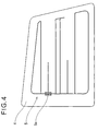
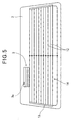
AM antenna 5 when viewed from the room interior of the vehicle. As shown in this figure, the antenna pattern of theAM antenna 5 is arranged substantially over the entire area of the fixedside window glass 4 to provide high sensitivity for the reception of AM broadcast signals. - FIG. 5 diagrammatically shows an antenna pattern of the
FM antenna 3 when viewed from the room interior of the vehicle. As shown in this figure, theFM antenna 3 is located above the defogger 14 (including the defogging heater elements 12) arranged in therear window glass 2. TheFM antenna 3 is offset from a vertical center line of therear window glass 2 but positioned close to thedefogger 14. - The reception sensitivity of a inventive transmission system and the reception sensitivity of a conventional transmission system with respect to frequencies of signals received at the AM antenna are shown in Table 1 below.
Sensitivity at AM band (unit: dB) Frequency (kHz) Transmission System 666 1035 1458 Inventive Transmission System with Impedance-matching Transformers -3.3 -2.0 -1.4 Conventional Transmission System with Low Capacitance Cable -13.4 -12.8 -11.2 - The inventive transmission system is constructed by the glass antenna device shown in FIGS. 2 and 3 and the
AM antenna 5 shown in FIG. 4, wherein reception signal received at theAM antenna 4 are transmitted through theimpedance converters - In the conventional transmission system, reception signal received at the
AM antenna 5 shown in FIG. 4 are transmitted to thereceiver 8 through a conventional low capacitance cable (capacitance=30 pF/m, length=4 m) without using theimpedance converters 6, 7 (this transmission system is hereinafter referred to as "Low-capacitance Cable Transmission System"). The reception sensitivities of the low-capacitance cable transmission system at respective measured frequencies are -13.4 dB at 666 kHz, -12.8 dB at 1035 kHz and -11.2 dB at 1458 kHz. - It appears clear from Table 1 that use of the transformer transmission system according to the present invention increases the reception sensitivity by about 10 dB as compared to the conventional low-capacitance cable transmission.
- The sensitivities shown in Table 1 are values as compared to the sensitivity of a 900-mm-length reference antenna attached to a fender of the vehicle. Stated in other words, the sensitivities shown in Table 1 are indicated in terms of the ratio of the receiver's input level of the reference antenna to the receiver's input level of the inventive transformer transmission system or of the conventional low-capacitance cable transmission system.
- FIG. 6 is a graphical representation of the FM band sensitivity plotted at frequencies using a horizontally polarized wave. The sensitivity shown in FIG. 6 is indicated in terms of the ratio of the receiver's input level of a antenna device using a dipole antenna as a reference antenna to the receiver's input level of a antenna device including the
FM antenna 3 shown in FIG. 5. - As evidenced from the graph shown in FIG. 6, the average FM band sensitivity of the inventive antenna device using the
FM antenna 3 of FIG. 5 is -12.8 dB which is sufficient for practical use. - In the embodiment described above, the
FM antenna 3 is provided on the vehiclerear window glass 2. The FM antenna may be arranged in the vehiclerear window glass 2 together with a TV antenna (not shown). Additionally, an antenna for mobile operation may be provided on therear window glass 2. Furthermore, an antenna for shortwave broadcast band may be provided on the rear window glass. - FIG. 7 is a graph showing the AM reception sensitivity versus distributed capacitance characteristics of the antenna device measured at a frequency of 1458 kHz.
- As evidenced from FIG. 7, the AM reception sensitivity increases with a reduction of the distributed capacitance, and in order to maintain the reception sensitivity within -6dB, the distribution capacitance shown be below 10 pF.
- The AM reception sensitivity shown in FIG. 7 is indicated in terms of values as compared to the sensitivity of a 900-mm-length reference antenna attached to a fender of the vehicle. Stated in other words, the sensitivity shown in FIG. 7 is indicated by way of the ratio of the receiver's input level of the reference antenna to the receiver's input level of the inventive antenna device.
- FIG. 8 shows a vehicle
glass antenna device 21 according to another embodiment of the present invention. - The
antenna device 21 shown in FIG. 8 is featured in that a firstcoaxial cable 9 for transmission of AM broadcast reception signals and a secondcoaxial cable 22 for transmission of FM broadcast reception signals are provided separately. - The reception signals at FM band received at an
FM antenna 3 are transmitted through the second coaxial cable (JIS 1.5C2V coaxial cable) to the proximity of areceiver 8, then supplied through an FM-pass and AMleakage prevention circuit 23 to an input terminal (antenna connecting terminal) 8a of thereceiver 8. The FM-pass and AMleakage prevention circuit 23 shown in the illustrated embodiment is comprised of a capacitor C23 and a choke coil L23 connected in series with each other. As an alternative, thiscircuit 23 may be comprised of thecapacitor 23 only. - A receiver-side impedance conversion circuit or
converter 27 is composed of a transformer T2 and a choke coil L2. - A third
coaxial cable 25 interconnects anoutput terminal 7b of the receiver-side impedance converter 27 and theinput terminal 8a of thereceiver 8. - FIG. 9 shows a vehicle glass antenna device according still another embodiment of the present invention.
- The
antenna device 31 shown in FIG. 9 differs from the antenna devices of the foregoing embodiments in that twoAM antennas window glass 4R and a vehicle left side fixedwindow glass 4L so as to further improve the AM reception sensitivity. - An AM-antenna-side impedance conversion circuit or
converter 6 is disposed adjacent to one of the right and left side fixedwindow glasses input terminal 6a of the AM-antenna-side impedance converter 6 are connected together by a low-capacitance coaxial cable 32 which is used to reduce attenuation of the reception signal (received at theAM antenna 5L shown in FIG. 9).
Claims (6)
- A glass antenna device for use with window glasses of a vehicle, comprising:a defogging heater (14) provided on a rear window glass (2) of the vehicle for defogging the rear window glass (2);a first receiving antenna (3) provided on the rear window glass (2) for the reception of radio waves in a frequency range above a shortwave band; anda second receiving antenna (5; 18) provided on a fixed side window glass (4) of the vehicle for the reception of radio waves at a medium wave band, the fixed side window glass (4) being located at a different position from the rear window glass (2).
- The glass antenna device of claim 1, wherein said first antenna (3) provided on the rear window glass (2) is an FM antenna for the reception of FM broadcasts, and said second antenna (5; 18) provided on the fixed side window glass (4) is an AM antenna for the reception of AM broadcasts.
- The glass antenna device of claim 1 or 2, wherein a signal received at said second antenna (5; 18) is transmitted through transformers (T1, T2) to a receiver (8).
- The glass antenna device of claim 2 or 3, wherein a signal received at said AM antenna (5; 18) is transmitted through transformers (T1, T2) to a receiver.
- The glass antenna device of claim 2, 3 or 4 wherein said FM antenna (3) is electrically connected by a coaxial cable (22) to a receiver (8) with an AM signal leakage preventing capacitor(C23) inserted between said coaxial cable (22) and said receiver (8).
- The glass antenna device of claim 2, 3, 4 or 5 further including an AM-antenna-side impedance converter (6) connected to said FM antenna (3) and said AM antenna (5, 18) through respective transmission lines for performing the impedance conversion of said transmission lines, and a receiver-side impedance converter (7) electrically connected to said AM-antenna-side impedance converter (6), and a receiver (8) connected by a cable (25) to said receiver-side impedance converter (7), wherein said cable (25) has a distributed capacitance below 10 pF.
Applications Claiming Priority (4)
| Application Number | Priority Date | Filing Date | Title |
|---|---|---|---|
| JP5993198 | 1998-03-11 | ||
| JP5993198 | 1998-03-11 | ||
| JP32531898 | 1998-11-16 | ||
| JP32531898A JP3562980B2 (en) | 1998-03-11 | 1998-11-16 | Glass antenna device for vehicles |
Publications (3)
| Publication Number | Publication Date |
|---|---|
| EP0942486A2 true EP0942486A2 (en) | 1999-09-15 |
| EP0942486A3 EP0942486A3 (en) | 2000-02-23 |
| EP0942486B1 EP0942486B1 (en) | 2005-08-24 |
Family
ID=26401001
Family Applications (1)
| Application Number | Title | Priority Date | Filing Date |
|---|---|---|---|
| EP99104554A Expired - Lifetime EP0942486B1 (en) | 1998-03-11 | 1999-03-08 | Glass antenna device for vehicle |
Country Status (5)
| Country | Link |
|---|---|
| US (1) | US6121934A (en) |
| EP (1) | EP0942486B1 (en) |
| JP (1) | JP3562980B2 (en) |
| KR (1) | KR19990077757A (en) |
| DE (1) | DE69926826T2 (en) |
Cited By (4)
| Publication number | Priority date | Publication date | Assignee | Title |
|---|---|---|---|---|
| EP1001485A2 (en) * | 1998-11-16 | 2000-05-17 | Nippon Sheet Glass Co., Ltd. | Glass antenna device for vehicle |
| EP1763105A1 (en) * | 2004-06-29 | 2007-03-14 | Nippon Sheet Glass Company, Limited | Hot-wire pattern structure of defogger formed on vehicle-use rear glass and vehicle-use rear glass |
| CN110998970A (en) * | 2017-08-02 | 2020-04-10 | 奥迪股份公司 | Antenna device for vehicle |
| CN111755796A (en) * | 2019-03-28 | 2020-10-09 | 中国航天科工飞航技术研究院(中国航天海鹰机电技术研究院) | Short wave antenna device based on metal road facility and implementation method |
Families Citing this family (10)
| Publication number | Priority date | Publication date | Assignee | Title |
|---|---|---|---|---|
| DE10010226A1 (en) * | 1999-08-31 | 2001-03-01 | Lindenmeier Heinz | Antenna arrangement for fixing to window of motor vehicle, has antenna connection terminal provided in free-field formed with window closed between sealing strip and window control device |
| KR20020078286A (en) * | 2001-04-09 | 2002-10-18 | 현대자동차주식회사 | Glass ant module |
| KR20030041319A (en) * | 2001-11-19 | 2003-05-27 | 기아자동차주식회사 | glass antenna for vehicles |
| JP2005026954A (en) * | 2003-07-01 | 2005-01-27 | Sharp Corp | Converter for receiving radio waves and antenna assembly |
| ATE519249T1 (en) * | 2007-03-27 | 2011-08-15 | Honda Motor Co Ltd | STRUCTURE FOR A RECTANGULAR FRAME ANTENNA |
| DE102008011131A1 (en) * | 2008-02-26 | 2009-09-10 | Bayerische Motoren Werke Aktiengesellschaft | Antenna arrangement for a motor vehicle |
| KR101736995B1 (en) | 2015-12-09 | 2017-05-17 | 현대자동차주식회사 | Method of removing common mode noise, avn system using the mothod, and vehicle including the same |
| EA202090403A1 (en) * | 2017-08-02 | 2020-04-29 | ЭйДжиСи Инк. | ANTENNA BLOCK FOR GLASS, GLASS SHEET WITH ANTENNA AND METHOD FOR PRODUCING ANTENNA BLOCK FOR GLASS |
| JP7138658B2 (en) * | 2017-12-06 | 2022-09-16 | 日本板硝子株式会社 | rear glass |
| JP2023023135A (en) * | 2021-08-04 | 2023-02-16 | Agc株式会社 | Window glass for vehicle |
Citations (7)
| Publication number | Priority date | Publication date | Assignee | Title |
|---|---|---|---|---|
| JPH0239702A (en) | 1988-07-29 | 1990-02-08 | Central Glass Co Ltd | Window glass antenna for automobile |
| JPH06224612A (en) | 1993-01-27 | 1994-08-12 | Central Glass Co Ltd | Glass antenna for vehicle |
| JPH06224611A (en) | 1993-01-27 | 1994-08-12 | Central Glass Co Ltd | Glass antenna for vehicle |
| JPH06268422A (en) | 1993-03-10 | 1994-09-22 | Asahi Glass Co Ltd | Glass antenna for automobile |
| JPH07111412A (en) | 1993-08-20 | 1995-04-25 | Asahi Glass Co Ltd | Glass antenna system for automobile |
| JPH0918222A (en) | 1995-06-28 | 1997-01-17 | Nippon Sheet Glass Co Ltd | Window glass antenna device |
| JPH09107218A (en) | 1995-08-08 | 1997-04-22 | Asahi Glass Co Ltd | Glass antenna system for vehicle |
Family Cites Families (14)
| Publication number | Priority date | Publication date | Assignee | Title |
|---|---|---|---|---|
| JPS61210705A (en) * | 1985-03-15 | 1986-09-18 | Asahi Glass Co Ltd | Diversity antenna system of automobile |
| JPH032975Y2 (en) * | 1985-05-30 | 1991-01-25 | ||
| CA1258705A (en) * | 1985-06-21 | 1989-08-22 | Hiroshi Kondo | Automobile antenna system |
| US5258728A (en) * | 1987-09-30 | 1993-11-02 | Fujitsu Ten Limited | Antenna circuit for a multi-band antenna |
| EP0367555A3 (en) * | 1988-11-02 | 1991-10-30 | Nippon Sheet Glass Co., Ltd. | Reception system on window glass |
| DE4003385C2 (en) * | 1990-02-05 | 1996-03-28 | Hirschmann Richard Gmbh Co | Antenna arrangement |
| JP3206912B2 (en) * | 1990-07-16 | 2001-09-10 | 日本板硝子株式会社 | Automotive window glass antenna |
| JPH0486102A (en) * | 1990-07-30 | 1992-03-18 | Central Glass Co Ltd | Glass antenna for vehicle |
| DE69326271T2 (en) * | 1992-03-27 | 1999-12-30 | Asahi Glass Co Ltd | Diversity window antenna for motor vehicles |
| JPH08162826A (en) * | 1994-12-02 | 1996-06-21 | Central Glass Co Ltd | Glass antenna for vehicle |
| JP3541979B2 (en) * | 1995-03-22 | 2004-07-14 | マツダ株式会社 | Glass antenna for vehicle and design method thereof |
| US5905470A (en) * | 1996-12-20 | 1999-05-18 | Central Glass Company, Limited | Vehicle side window glass antenna for radio broadcast waves |
| US5883599A (en) * | 1997-01-16 | 1999-03-16 | Ford Motor Company | Antenna system for a motor vehicle |
| US5940042A (en) * | 1997-09-05 | 1999-08-17 | Northrop Grumman Corporation | Windshield slot antenna for vehicle transmissions |
-
1998
- 1998-11-16 JP JP32531898A patent/JP3562980B2/en not_active Expired - Fee Related
-
1999
- 1999-03-08 DE DE69926826T patent/DE69926826T2/en not_active Expired - Lifetime
- 1999-03-08 EP EP99104554A patent/EP0942486B1/en not_active Expired - Lifetime
- 1999-03-10 KR KR1019990007992A patent/KR19990077757A/en not_active Application Discontinuation
- 1999-03-10 US US09/266,412 patent/US6121934A/en not_active Expired - Fee Related
Patent Citations (7)
| Publication number | Priority date | Publication date | Assignee | Title |
|---|---|---|---|---|
| JPH0239702A (en) | 1988-07-29 | 1990-02-08 | Central Glass Co Ltd | Window glass antenna for automobile |
| JPH06224612A (en) | 1993-01-27 | 1994-08-12 | Central Glass Co Ltd | Glass antenna for vehicle |
| JPH06224611A (en) | 1993-01-27 | 1994-08-12 | Central Glass Co Ltd | Glass antenna for vehicle |
| JPH06268422A (en) | 1993-03-10 | 1994-09-22 | Asahi Glass Co Ltd | Glass antenna for automobile |
| JPH07111412A (en) | 1993-08-20 | 1995-04-25 | Asahi Glass Co Ltd | Glass antenna system for automobile |
| JPH0918222A (en) | 1995-06-28 | 1997-01-17 | Nippon Sheet Glass Co Ltd | Window glass antenna device |
| JPH09107218A (en) | 1995-08-08 | 1997-04-22 | Asahi Glass Co Ltd | Glass antenna system for vehicle |
Cited By (8)
| Publication number | Priority date | Publication date | Assignee | Title |
|---|---|---|---|---|
| EP1001485A2 (en) * | 1998-11-16 | 2000-05-17 | Nippon Sheet Glass Co., Ltd. | Glass antenna device for vehicle |
| EP1001485A3 (en) * | 1998-11-16 | 2000-09-13 | Nippon Sheet Glass Co., Ltd. | Glass antenna device for vehicle |
| US6229493B1 (en) | 1998-11-16 | 2001-05-08 | Nippon Sheet Glass Co., Ltd. | Glass antenna device for vehicle |
| EP1763105A1 (en) * | 2004-06-29 | 2007-03-14 | Nippon Sheet Glass Company, Limited | Hot-wire pattern structure of defogger formed on vehicle-use rear glass and vehicle-use rear glass |
| EP1763105A4 (en) * | 2004-06-29 | 2008-01-16 | Nippon Sheet Glass Co Ltd | Hot-wire pattern structure of defogger formed on vehicle-use rear glass and vehicle-use rear glass |
| US7671298B2 (en) | 2004-06-29 | 2010-03-02 | Fujitsu Ten Limited | Heating line pattern structure of defogger formed on rear window glass panel of motor vehicle and rear glass panel |
| CN110998970A (en) * | 2017-08-02 | 2020-04-10 | 奥迪股份公司 | Antenna device for vehicle |
| CN111755796A (en) * | 2019-03-28 | 2020-10-09 | 中国航天科工飞航技术研究院(中国航天海鹰机电技术研究院) | Short wave antenna device based on metal road facility and implementation method |
Also Published As
| Publication number | Publication date |
|---|---|
| EP0942486B1 (en) | 2005-08-24 |
| US6121934A (en) | 2000-09-19 |
| DE69926826T2 (en) | 2006-03-09 |
| DE69926826D1 (en) | 2005-09-29 |
| JPH11330832A (en) | 1999-11-30 |
| EP0942486A3 (en) | 2000-02-23 |
| JP3562980B2 (en) | 2004-09-08 |
| KR19990077757A (en) | 1999-10-25 |
Similar Documents
| Publication | Publication Date | Title |
|---|---|---|
| KR100287566B1 (en) | Automotive glass antenna device | |
| KR100386994B1 (en) | Automotive glass antenna device | |
| US5289197A (en) | Pane antenna having an amplifier | |
| EP0942486B1 (en) | Glass antenna device for vehicle | |
| CA2287452C (en) | Glass antenna device for vehicle | |
| US6130645A (en) | Combination wide band antenna and heating element on a window of a vehicle | |
| US5610619A (en) | Backlite antenna for AM/FM automobile radio having broadband FM reception | |
| US5285048A (en) | Automobile windshield antenna incorporating windshield heater | |
| EP0963002A1 (en) | Glass window antenna system for motor vehicles | |
| EP0367225B1 (en) | A glass window antenna for use in a motor vehicle | |
| US6064345A (en) | Glass antenna device for an automobile | |
| US5790079A (en) | Backlite antenna for AM/FM automobile radio | |
| US6201505B1 (en) | Glass antenna device for an automobile | |
| EP1100144A2 (en) | Vehicle glass antenna | |
| JPH03108903A (en) | Wideband loop antenna | |
| JP3700372B2 (en) | Glass antenna device for vehicle | |
| JPH04249405A (en) | Automobile glass antenna | |
| JP3508217B2 (en) | Automotive glass antenna device | |
| US4352107A (en) | Matching cable for automobile antennas for receiving FM broadcasts | |
| JP3648910B2 (en) | Vehicle antenna | |
| JP2000101323A (en) | On-glass antenna system for automobile | |
| JPH02256303A (en) | Glass antenna system for automobile | |
| JP2000059124A (en) | Glass antenna system for automobile | |
| KR200289601Y1 (en) | Glass antenna for automobiles | |
| JPH0865025A (en) | Fm-tv glass antenna device for automobile |
Legal Events
| Date | Code | Title | Description |
|---|---|---|---|
| PUAI | Public reference made under article 153(3) epc to a published international application that has entered the european phase |
Free format text: ORIGINAL CODE: 0009012 |
|
| AK | Designated contracting states |
Kind code of ref document: A2 Designated state(s): DE GB |
|
| AX | Request for extension of the european patent |
Free format text: AL;LT;LV;MK;RO;SI |
|
| PUAL | Search report despatched |
Free format text: ORIGINAL CODE: 0009013 |
|
| AK | Designated contracting states |
Kind code of ref document: A3 Designated state(s): AT BE CH CY DE DK ES FI FR GB GR IE IT LI LU MC NL PT SE |
|
| AX | Request for extension of the european patent |
Free format text: AL;LT;LV;MK;RO;SI |
|
| 17P | Request for examination filed |
Effective date: 20000321 |
|
| AKX | Designation fees paid |
Free format text: DE GB |
|
| 17Q | First examination report despatched |
Effective date: 20030505 |
|
| GRAP | Despatch of communication of intention to grant a patent |
Free format text: ORIGINAL CODE: EPIDOSNIGR1 |
|
| GRAS | Grant fee paid |
Free format text: ORIGINAL CODE: EPIDOSNIGR3 |
|
| GRAA | (expected) grant |
Free format text: ORIGINAL CODE: 0009210 |
|
| AK | Designated contracting states |
Kind code of ref document: B1 Designated state(s): DE GB |
|
| REG | Reference to a national code |
Ref country code: GB Ref legal event code: FG4D |
|
| REF | Corresponds to: |
Ref document number: 69926826 Country of ref document: DE Date of ref document: 20050929 Kind code of ref document: P |
|
| PG25 | Lapsed in a contracting state [announced via postgrant information from national office to epo] |
Ref country code: GB Free format text: LAPSE BECAUSE OF NON-PAYMENT OF DUE FEES Effective date: 20060308 |
|
| PLBE | No opposition filed within time limit |
Free format text: ORIGINAL CODE: 0009261 |
|
| STAA | Information on the status of an ep patent application or granted ep patent |
Free format text: STATUS: NO OPPOSITION FILED WITHIN TIME LIMIT |
|
| 26N | No opposition filed |
Effective date: 20060526 |
|
| GBPC | Gb: european patent ceased through non-payment of renewal fee |
Effective date: 20060308 |
|
| PGFP | Annual fee paid to national office [announced via postgrant information from national office to epo] |
Ref country code: DE Payment date: 20100318 Year of fee payment: 12 |
|
| PG25 | Lapsed in a contracting state [announced via postgrant information from national office to epo] |
Ref country code: DE Free format text: LAPSE BECAUSE OF NON-PAYMENT OF DUE FEES Effective date: 20111001 |
|
| REG | Reference to a national code |
Ref country code: DE Ref legal event code: R119 Ref document number: 69926826 Country of ref document: DE Effective date: 20111001 |