EP0940501A2 - Gloss control system using air jets - Google Patents
Gloss control system using air jets Download PDFInfo
- Publication number
- EP0940501A2 EP0940501A2 EP99103196A EP99103196A EP0940501A2 EP 0940501 A2 EP0940501 A2 EP 0940501A2 EP 99103196 A EP99103196 A EP 99103196A EP 99103196 A EP99103196 A EP 99103196A EP 0940501 A2 EP0940501 A2 EP 0940501A2
- Authority
- EP
- European Patent Office
- Prior art keywords
- roll
- gloss
- control system
- web
- calender roll
- Prior art date
- Legal status (The legal status is an assumption and is not a legal conclusion. Google has not performed a legal analysis and makes no representation as to the accuracy of the status listed.)
- Withdrawn
Links
Images

Classifications
-
- D—TEXTILES; PAPER
- D21—PAPER-MAKING; PRODUCTION OF CELLULOSE
- D21G—CALENDERS; ACCESSORIES FOR PAPER-MAKING MACHINES
- D21G1/00—Calenders; Smoothing apparatus
- D21G1/02—Rolls; Their bearings
- D21G1/0253—Heating or cooling the rolls; Regulating the temperature
- D21G1/0286—Regulating the axial or circumferential temperature profile of the roll
-
- D—TEXTILES; PAPER
- D21—PAPER-MAKING; PRODUCTION OF CELLULOSE
- D21G—CALENDERS; ACCESSORIES FOR PAPER-MAKING MACHINES
- D21G1/00—Calenders; Smoothing apparatus
- D21G1/02—Rolls; Their bearings
- D21G1/0253—Heating or cooling the rolls; Regulating the temperature
- D21G1/0266—Heating or cooling the rolls; Regulating the temperature using a heat-transfer fluid
- D21G1/0273—Heating or cooling the rolls; Regulating the temperature using a heat-transfer fluid on the exterior surface of the rolls
Definitions
- the present invention is directed to a gloss system using air jets and more specifically where the air jets are directed toward the uncovered surface of an associated calender roll.
- a surface gloss is produced depending on the type of paper; for example, magazine or newsprint.
- calendering rolls impart a gloss to the surface of the moving paper web.
- the surface of the calender roll is a hard cylindrical material (steel) and by the use of heat and pressure, the range of gloss development is controlled.
- the surface of the polished metal calender roll is replicated.
- the application of steam creates too much moisture which affects other parameters of the paper, such as thickness, basic weight, moisture content, etc.
- the oil or inductive coil technique is very slow.
- the steel rolls which may be 8 or 10 stacked on top of each other commingled with pressure and idler rolls, do not have internal access.
- a specific object of the invention is to provide a gloss control system where the cross direction thickness of the web is unaffected by the gloss control.
- a gloss control system having at least one calender roll rotatable about its axis having a hard cylindrical surface for storing heat and where a moving web of calenderable material is in contact with a segment of said cylindrical surface and pressed against such surface by an adjacent roll. The width of the web is less than the axial length of the calender roll to leave the two ends of the calender roll not covered by the web.
- the system comprises a plurality of air jet means in close proximity to a segment of the cylindrical surface of the calender roll, not in contact with the moving web, arranged along a plurality of zones in the direction of the roll axis, for directing air at said roll surface along its entire axis including means for selectively heating or cooling the air jets from zone to zone.
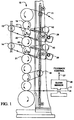
- Figure 1 illustrates what is termed in the paper industry a super calender system of rolls.
- a web of calenderable material such as paper 11 is fed into the vertical stack of rolls 12, and the paper passes between the rolls in a general S-path configuration being interrupted by idler rolls 13, 14 and 16.
- the vertical roll stack 12 consists of two types of rolls - first are normal calender rolls such as 17 and 18 having a hard highly polished cylindrical surface generally of steel, which effectively stores heat, and then adjacent rolls to the steel rolls such as 19, 20 and 21, which are softer rolls, for example, being made of an artificial substance such as nomex.
- normal calender rolls such as 17 and 18 having a hard highly polished cylindrical surface generally of steel, which effectively stores heat
- adjacent rolls to the steel rolls such as 19, 20 and 21, which are softer rolls, for example, being made of an artificial substance such as nomex.
- the rolls 12 have no internal access.
- heat is applied to the paper web 11 adjacent to the roll by a separate steam unit such as disclosed in the above '529 patent. Where inductive heating or hot oil is used, this would be another calendering segment of the paper making process normally upstream from the present super calender system.
- the gloss sensor unit 26 provides a feedback control signal 27 to indicate whether the heat supplied to the system must be increased or decreased to change the gloss level. And, of course, normally such heat control would in a super calender system control steam units or in an upstream mode the more normal calender gloss unit having internal heating.
- heat is applied to the segment of both rolls 17 and 18 (not in contact with paper web 11) indicated by 17' and 18' , by a pair of air jet units 28 and 29 mounted in close proximity to the segments 17' and 18'.
- FIG 2 is a simplified end view of the air jet units which are disclosed and claimed fully in U.S. patent 4,573,402, assigned to the present assignee.
- the air jet units are sold under the trademark THERMA-JET.
- THERMA-JET Generally such units are used for controlling the caliper of the web of paper by controlling the temperature of air impinging on an adjacent calender roll.
- the expansion of the calender roll is changed to directly affect the thickness or caliper of the paper.
- the air jet unit has a plenum chamber 31 where air from an ambient source is taken in and then passed through individually controlled electrical heating elements 32 mounted in close proximity to a curved apertured faceplate 33. This is then placed adjacent the uncontacted segments 17' or 18' of the calender roll indicated in Figure 1.
- Figure 3 illustrates the longitudinal arrangement of the air jet unit 28 which extends along a plurality of zones in the direction of the roll axis 17' of roll 17.
- Each zone depending on the design of the air jet unit, may be, for example, 1-1/2 inches wide and contain 1 or 2 individually controlled heating elements 32.
- the ambient air supply at 34 is indicated. The air is directed along the entire axis 17' of the roll including ends 36 and 37 not covered by the paper web.
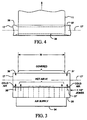
- Figure 4 shows the paper web 11 as having a width W as it would contact another segment of roll 17. This is looking down on the roll as it is shown in Figure 1.
- the paper web 11 tends to cool steel roll 17 to thus cause a contraction in its diameter, except at the uncovered ends 36 and 37, to produce an hourglass shape indicated by the dashed lines 38. As discussed above, this is undesirable in causing larger diameter ends of the roll to affect the paper thickness making the profile uneven and also the gloss. It is desired to equalize expansion or contraction of the diameter of the roll along its entire axis 17' both covered and uncovered.
- the air jet units 28 for the uncovered end sections 36 and 37 provide relatively cold air indicated by the arrows 36' and 37' to thus simulate the cooling effect of the paper web 11.
- the air jet units 28 because of the individually controlled heating elements 32, shown in Figure 2, can easily accommodate this temperature difference.
- the cold air supplied at 36' and 37' is actually unheated air (or minimally heated) and the remainder of the air designated hot air 41, heats the surface of the calender roll 17 to a desired temperature to produce the desired gloss.
- This can either be done on a cross direction zone by zone basis or in a more typical case the hot air 41 temperature would be the same along the entire width W of the web 11.
- the feedback control is used to control the surface temperature and heat stored by the roll to thereby control the transfer of heat from the calender roll to the web to control its gloss. Gloss is controlled, for example, by plasticizing the surface at approximately a temperature of 160°F.
- the width, W, of paper web 11 may be typically 95% of the entire axial length of roll 17. However, depending on the paper being produced, the width may be as little as 50% of the axial length. Nevertheless, the air jet units 28 may easily compensate in the same manner since the air jets are divided into individually controlled heating zones. And the relatively cold air at the uncovered ends may be precisely controlled on an axial basis.
- the present system especially in the context of super calender rolls where no internal access of a calender roll is available, allows more effective control of gloss in general either with or without specific cross direction control. This is an improvement over steam units which have moisture problems. In addition it is an improvement where access is available over internally heated rolls heated either by internal induction or oil which is very slow. Finally the hourglass problem is corrected.
Abstract
Description
A specific object of the invention is to provide a gloss control system where the cross direction thickness of the web is unaffected by the gloss control.
In accordance with the above object there is provided a gloss control system having at least one calender roll rotatable about its axis having a hard cylindrical surface for storing heat and where a moving web of calenderable material is in contact with a segment of said cylindrical surface and pressed against such surface by an adjacent roll. The width of the web is less than the axial length of the calender roll to leave the two ends of the calender roll not covered by the web. The system comprises a plurality of air jet means in close proximity to a segment of the cylindrical surface of the calender roll, not in contact with the moving web, arranged along a plurality of zones in the direction of the roll axis, for directing air at said roll surface along its entire axis including means for selectively heating or cooling the air jets from zone to zone.
Claims (7)
- A gloss control system having at least one calender roll rotatable about its axis having a hard cylindrical surface for storing heat and where a moving web of calenderable material is in contact with a segment of said cylindrical surface and pressed against said surface by an adjacent roll, the width of said web being less than the axial length of said calender roll to leave the two ends of the calender roll not covered by said web, said system comprising:a plurality of air jet means in close proximity to a segment of said cylindrical surface of said calender roll, not in contact with said moving web, arranged along a plurality of zones in the direction of said roll axis, for directing air at said roll surface along its entire axis including means for selectively heating or cooling said air jets from zone to zone.
- A gloss control system as in Claim 1 including feedback control means where said air jet means heat said roll surface to control the transfer of heat to said calenderable web to control its gloss.
- A gloss control system as in Claim 1 where said air jet means for zones of said uncovered ends of said roll provide relatively cool air compared to the covered segment of such roll to equalize expansion or contraction of the diameter of said roll along its entire axis.
- A gloss control system as in Claim 1 where said air jet means include a plurality of electrical heating elements in close proximity to said calender roll.
- A gloss control system as in Claim 1 where said calender roll has no internal access.
- A gloss control system as in Claim 2 where said feedback control means provides cross direction control of gloss.
- A gloss control system as in Claim 1 where the cross direction thickness of said web is unaffected by said gloss control.
Applications Claiming Priority (2)
| Application Number | Priority Date | Filing Date | Title |
|---|---|---|---|
| US35693 | 1998-03-05 | ||
| US09/035,693 US6000328A (en) | 1998-03-05 | 1998-03-05 | Gloss control system using air jets |
Publications (2)
| Publication Number | Publication Date |
|---|---|
| EP0940501A2 true EP0940501A2 (en) | 1999-09-08 |
| EP0940501A3 EP0940501A3 (en) | 2000-05-10 |
Family
ID=21884258
Family Applications (1)
| Application Number | Title | Priority Date | Filing Date |
|---|---|---|---|
| EP99103196A Withdrawn EP0940501A3 (en) | 1998-03-05 | 1999-02-18 | Gloss control system using air jets |
Country Status (4)
| Country | Link |
|---|---|
| US (1) | US6000328A (en) |
| EP (1) | EP0940501A3 (en) |
| JP (1) | JPH11286888A (en) |
| CA (1) | CA2264405A1 (en) |
Cited By (1)
| Publication number | Priority date | Publication date | Assignee | Title |
|---|---|---|---|---|
| US7423758B1 (en) | 2007-07-27 | 2008-09-09 | Voith Patent Gmbh | Gloss sensor for a paper machine |
Citations (6)
| Publication number | Priority date | Publication date | Assignee | Title |
|---|---|---|---|---|
| US4768433A (en) * | 1985-01-25 | 1988-09-06 | Measurex Corporation | Hot air calender roll controller |
| US4823688A (en) * | 1987-08-10 | 1989-04-25 | Beloit Corporation | Calendering apparatus using inductive heating for hot-calendering a paper web |
| DE9207957U1 (en) * | 1991-08-29 | 1992-08-13 | Sulzer-Escher Wyss Gmbh, 7980 Ravensburg, De | |
| EP0554698A1 (en) * | 1992-02-01 | 1993-08-11 | Voith Sulzer Finishing GmbH | Cylinder machine |
| DE19528833A1 (en) * | 1994-08-19 | 1996-02-22 | Abb Ind Systems Inc | Controlling the throttling valves on a calender roll operating device |
| US5673616A (en) * | 1993-06-24 | 1997-10-07 | Sulzer Escher-Wyss Gmbh | Apparatus for influencing the thickness and gloss and/or smoothness in the treatment of fiber material webs |
Family Cites Families (4)
| Publication number | Priority date | Publication date | Assignee | Title |
|---|---|---|---|---|
| US3190212A (en) * | 1963-05-27 | 1965-06-22 | Beloit Corp | Gloss calender |
| US3770578A (en) * | 1971-05-12 | 1973-11-06 | Midland Ross Corp | Method for controlling caliper |
| US4114528A (en) * | 1976-03-02 | 1978-09-19 | Midland-Ross Corporation | Apparatus for web caliper control |
| US4748906A (en) * | 1986-03-21 | 1988-06-07 | Accuray Corporation | Air shower apparatus and method |
-
1998
- 1998-03-05 US US09/035,693 patent/US6000328A/en not_active Expired - Fee Related
-
1999
- 1999-02-18 EP EP99103196A patent/EP0940501A3/en not_active Withdrawn
- 1999-03-04 CA CA002264405A patent/CA2264405A1/en not_active Abandoned
- 1999-03-04 JP JP11057059A patent/JPH11286888A/en active Pending
Patent Citations (6)
| Publication number | Priority date | Publication date | Assignee | Title |
|---|---|---|---|---|
| US4768433A (en) * | 1985-01-25 | 1988-09-06 | Measurex Corporation | Hot air calender roll controller |
| US4823688A (en) * | 1987-08-10 | 1989-04-25 | Beloit Corporation | Calendering apparatus using inductive heating for hot-calendering a paper web |
| DE9207957U1 (en) * | 1991-08-29 | 1992-08-13 | Sulzer-Escher Wyss Gmbh, 7980 Ravensburg, De | |
| EP0554698A1 (en) * | 1992-02-01 | 1993-08-11 | Voith Sulzer Finishing GmbH | Cylinder machine |
| US5673616A (en) * | 1993-06-24 | 1997-10-07 | Sulzer Escher-Wyss Gmbh | Apparatus for influencing the thickness and gloss and/or smoothness in the treatment of fiber material webs |
| DE19528833A1 (en) * | 1994-08-19 | 1996-02-22 | Abb Ind Systems Inc | Controlling the throttling valves on a calender roll operating device |
Cited By (1)
| Publication number | Priority date | Publication date | Assignee | Title |
|---|---|---|---|---|
| US7423758B1 (en) | 2007-07-27 | 2008-09-09 | Voith Patent Gmbh | Gloss sensor for a paper machine |
Also Published As
| Publication number | Publication date |
|---|---|
| CA2264405A1 (en) | 1999-09-05 |
| EP0940501A3 (en) | 2000-05-10 |
| JPH11286888A (en) | 1999-10-19 |
| US6000328A (en) | 1999-12-14 |
Similar Documents
| Publication | Publication Date | Title |
|---|---|---|
| US4653395A (en) | Method and apparatus in the calendering of a web | |
| US5074019A (en) | Roll with induction heating arrangement | |
| JP4008504B2 (en) | Calendaring method and calendar using the method | |
| US5524532A (en) | Method and apparatus for calendering a paper or board web | |
| US4823688A (en) | Calendering apparatus using inductive heating for hot-calendering a paper web | |
| EP0672785B1 (en) | Paper calendering apparatus | |
| US6182564B1 (en) | Apparatus and process for the smoothing of a material web | |
| US6689993B2 (en) | Method and device for induction heating a roll | |
| US6000328A (en) | Gloss control system using air jets | |
| EP0840821B1 (en) | Method of calendering of a paper web and a calender that makes use of the method | |
| US5932069A (en) | Paper machine roll with heated ends in a soft calender or supercalender and method for calendering a web | |
| EP1330573A1 (en) | Method and arrangement for calendering a web comprising a long-nip calender | |
| US5673616A (en) | Apparatus for influencing the thickness and gloss and/or smoothness in the treatment of fiber material webs | |
| US6368458B1 (en) | Calender press for a paper-making machine with thermally compensated top and bottom rolls and low nip load | |
| US5240564A (en) | Method for the control of the nip-pressure profile in a paper making machine | |
| US7662262B2 (en) | Supercalendering optimization using a steam shower | |
| CN201924229U (en) | Calendar | |
| US3359643A (en) | Production of paper | |
| WO1990014216A1 (en) | Calendering control system | |
| JP3949259B2 (en) | Heating roller device | |
| JPH0771443A (en) | Hollow roll for travelling of raw material web | |
| WO2001042562A2 (en) | Thermoroll | |
| JP2000220089A (en) | Shoe roll |
Legal Events
| Date | Code | Title | Description |
|---|---|---|---|
| PUAI | Public reference made under article 153(3) epc to a published international application that has entered the european phase |
Free format text: ORIGINAL CODE: 0009012 |
|
| 17P | Request for examination filed |
Effective date: 19990218 |
|
| AK | Designated contracting states |
Kind code of ref document: A2 Designated state(s): DE FI GB |
|
| AX | Request for extension of the european patent |
Free format text: AL;LT;LV;MK;RO;SI |
|
| PUAL | Search report despatched |
Free format text: ORIGINAL CODE: 0009013 |
|
| AK | Designated contracting states |
Kind code of ref document: A3 Designated state(s): AT BE CH CY DE DK ES FI FR GB GR IE IT LI LU MC NL PT SE |
|
| AX | Request for extension of the european patent |
Free format text: AL;LT;LV;MK;RO;SI |
|
| RIC1 | Information provided on ipc code assigned before grant |
Free format text: 7D 21G 1/00 A, 7D 21G 1/02 B |
|
| AKX | Designation fees paid |
Free format text: DE FI GB |
|
| STAA | Information on the status of an ep patent application or granted ep patent |
Free format text: STATUS: THE APPLICATION IS DEEMED TO BE WITHDRAWN |
|
| 18D | Application deemed to be withdrawn |
Effective date: 20000511 |