EP0938975A2 - Apparatus and method for image fusing - Google Patents
Apparatus and method for image fusingInfo
- Publication number
- EP0938975A2 EP0938975A2 EP99301400A EP99301400A EP0938975A2 EP 0938975 A2 EP0938975 A2 EP 0938975A2 EP 99301400 A EP99301400 A EP 99301400A EP 99301400 A EP99301400 A EP 99301400A EP 0938975 A2 EP0938975 A2 EP 0938975A2
- Authority
- EP
- European Patent Office
- Prior art keywords
- nip
- receiving substrate
- final receiving
- ink
- fuser roller
- Prior art date
- Legal status (The legal status is an assumption and is not a legal conclusion. Google has not performed a legal analysis and makes no representation as to the accuracy of the status listed.)
- Granted
Links
Images

Classifications
-
- B—PERFORMING OPERATIONS; TRANSPORTING
- B41—PRINTING; LINING MACHINES; TYPEWRITERS; STAMPS
- B41J—TYPEWRITERS; SELECTIVE PRINTING MECHANISMS, i.e. MECHANISMS PRINTING OTHERWISE THAN FROM A FORME; CORRECTION OF TYPOGRAPHICAL ERRORS
- B41J2/00—Typewriters or selective printing mechanisms characterised by the printing or marking process for which they are designed
- B41J2/005—Typewriters or selective printing mechanisms characterised by the printing or marking process for which they are designed characterised by bringing liquid or particles selectively into contact with a printing material
- B41J2/01—Ink jet
- B41J2/135—Nozzles
- B41J2/14—Structure thereof only for on-demand ink jet heads
- B41J2/14016—Structure of bubble jet print heads
-
- B—PERFORMING OPERATIONS; TRANSPORTING
- B41—PRINTING; LINING MACHINES; TYPEWRITERS; STAMPS
- B41J—TYPEWRITERS; SELECTIVE PRINTING MECHANISMS, i.e. MECHANISMS PRINTING OTHERWISE THAN FROM A FORME; CORRECTION OF TYPOGRAPHICAL ERRORS
- B41J11/00—Devices or arrangements of selective printing mechanisms, e.g. ink-jet printers or thermal printers, for supporting or handling copy material in sheet or web form
- B41J11/0015—Devices or arrangements of selective printing mechanisms, e.g. ink-jet printers or thermal printers, for supporting or handling copy material in sheet or web form for treating before, during or after printing or for uniform coating or laminating the copy material before or after printing
- B41J11/002—Curing or drying the ink on the copy materials, e.g. by heating or irradiating
- B41J11/0024—Curing or drying the ink on the copy materials, e.g. by heating or irradiating using conduction means, e.g. by using a heated platen
- B41J11/00242—Controlling the temperature of the conduction means
-
- B—PERFORMING OPERATIONS; TRANSPORTING
- B41—PRINTING; LINING MACHINES; TYPEWRITERS; STAMPS
- B41J—TYPEWRITERS; SELECTIVE PRINTING MECHANISMS, i.e. MECHANISMS PRINTING OTHERWISE THAN FROM A FORME; CORRECTION OF TYPOGRAPHICAL ERRORS
- B41J2/00—Typewriters or selective printing mechanisms characterised by the printing or marking process for which they are designed
- B41J2/005—Typewriters or selective printing mechanisms characterised by the printing or marking process for which they are designed characterised by bringing liquid or particles selectively into contact with a printing material
- B41J2/01—Ink jet
- B41J2/135—Nozzles
- B41J2/145—Arrangement thereof
- B41J2/155—Arrangement thereof for line printing
-
- B—PERFORMING OPERATIONS; TRANSPORTING
- B41—PRINTING; LINING MACHINES; TYPEWRITERS; STAMPS
- B41J—TYPEWRITERS; SELECTIVE PRINTING MECHANISMS, i.e. MECHANISMS PRINTING OTHERWISE THAN FROM A FORME; CORRECTION OF TYPOGRAPHICAL ERRORS
- B41J2/00—Typewriters or selective printing mechanisms characterised by the printing or marking process for which they are designed
- B41J2/005—Typewriters or selective printing mechanisms characterised by the printing or marking process for which they are designed characterised by bringing liquid or particles selectively into contact with a printing material
- B41J2/01—Ink jet
- B41J2/17—Ink jet characterised by ink handling
- B41J2/175—Ink supply systems ; Circuit parts therefor
- B41J2/17593—Supplying ink in a solid state
-
- B—PERFORMING OPERATIONS; TRANSPORTING
- B41—PRINTING; LINING MACHINES; TYPEWRITERS; STAMPS
- B41J—TYPEWRITERS; SELECTIVE PRINTING MECHANISMS, i.e. MECHANISMS PRINTING OTHERWISE THAN FROM A FORME; CORRECTION OF TYPOGRAPHICAL ERRORS
- B41J2/00—Typewriters or selective printing mechanisms characterised by the printing or marking process for which they are designed
- B41J2/005—Typewriters or selective printing mechanisms characterised by the printing or marking process for which they are designed characterised by bringing liquid or particles selectively into contact with a printing material
- B41J2/01—Ink jet
- B41J2002/012—Ink jet with intermediate transfer member
-
- B—PERFORMING OPERATIONS; TRANSPORTING
- B41—PRINTING; LINING MACHINES; TYPEWRITERS; STAMPS
- B41J—TYPEWRITERS; SELECTIVE PRINTING MECHANISMS, i.e. MECHANISMS PRINTING OTHERWISE THAN FROM A FORME; CORRECTION OF TYPOGRAPHICAL ERRORS
- B41J25/00—Actions or mechanisms not otherwise provided for
- B41J2025/008—Actions or mechanisms not otherwise provided for comprising a plurality of print heads placed around a drum
Definitions
- This invention relates generally to an apparatus and method for image fusing in an ink jet printing system and, more specifically, to an apparatus and method that utilize separate image transfer and image fusing operations for improved fusing of an ink image into media.
- Ink jet printing involves ejecting ink droplets from orifices in a print head onto a receiving surface to form an image.
- the image is made up of a grid-like pattern of potential drop locations, commonly referred to as pixels.
- the resolution of the image is expressed by the number of ink drops or dots per inch (dpi), with common resolutions being 300 dpi and 600dpi.
- Ink-jet printing systems commonly utilize either direct printing or offset printing architecture.
- ink is ejected from jets in the print head directly onto the final receiving substrate.
- offset printing system the image is formed on an intermediate transfer surface and subsequently transferred to the final receiving substrate.
- the intermediate transfer surface may take the form of a liquid layer that is applied to a support surface, such as a drum.
- the print head jets the ink onto the intermediate transfer surface to form an ink image thereon. Once the ink image has been fully deposited, the final receiving substrate is then brought into contact with the intermediate transfer surface and the ink image is transferred to the final receiving substrate.
- U.S. Patent 5,389,958 entitled IMAGING PROCESS and assigned to the assignee of the present application is an example of an indirect or offset printing architecture that utilizes phase change ink.
- the intermediate transfer surface is applied by a wicking pad that is housed within an applicator apparatus. Prior to imaging, the applicator is raised into contact with the rotating drum to apply or replenish the liquid intermediate transfer surface.
- the applicator is retracted and the print head ejects drops of ink to form the ink image on the liquid intermediate transfer surface.
- the ink is applied in molten form, having been melted from its solid state form.
- the ink image solidifies on the liquid intermediate transfer surface by cooling to a malleable solid intermediate state as the drum continues to rotate.
- a transfer roller is moved into contact with the drum to form a pressurized transfer nip between the roller and the curved surface of the intermediate transfer surface/drum.
- a final receiving substrate such as a sheet of media, is then fed into the transfer nip and the ink image is transferred to the final receiving substrate.
- US Patent No 5,777,650 entitled PRESSURE ROLLER and assigned to the assignee of the present application discloses a roller for fixing an ink image on a final receiving substrate.
- the preferred embodiment of the roller is described in the context of an offset ink jet printing apparatus similar to the one described in the '958 patent.
- the final receiving medium is preheated to a preferred temperature of about 63° C and the pressure in the transfer nip is preferably about 1150 psi (7,929 kPa). Additionally, the speed of the final receiving medium through the transfer nip is approximately five inches/sec. (13cm./sec.).
- the ink image on the final receiving surface is composed of individual drops of ink that form primary and secondary colors.
- the primary and/or secondary colors may include two or more drops of ink placed on top of one another.
- the ink image is transferred from the drum to the final receiving substrate. A portion of the ink image is fused or pressed into the final receiving substrate. The height of the remaining ink that lays above the surface of the final receiving substrate is referred to as the "ink pile height.”
- the ink pile height of an image affects the "look and feel" of the image. In general, a lower ink pile height is preferred, as the appearance of the image will more closely resemble an image created by a commercial web press.
- the ink pile height also affects the ability of a user to write on the image. In images having ink pile heights approaching 1 x 10 -3 in., and higher, the tip of a writing instrument will often furrow through the ink "pile.” This can hinder the flow of writing ink through a ball point pen, or prevent the graphite writing surface of a pencil from contacting and marking the receiving substrate. Additionally, depending upon the composition of the ink used in the printer, ink pile height can hinder media from being transported through an automatic document feeder in a photocopier.
- the ink pile height of images on the final receiving surface ranges from about 1 x 10 -5 inch for a single pixel primary color to about 1 x 10 -3 in. for a solid fill secondary color.
- a liquid ink jet printer using a direct printing process and an aqueous-based ink produces images having a negligible ink pile height of less than 1 x 10 -5 inch.
- the apparatus and method utilize separate image transfer and fusing operations for improved fusing of an ink image into media.
- the apparatus and method allow faster print speeds by utilizing separate image transfer and fusing operations.
- the fusing operation may be utilized to apply a coating to the final receiving substrate.
- the apparatus and method are capable of producing images having an ink pile height of 7 x 10 -4 inch and less.
- the apparatus and method are capable of reducing the ink pile height in images for better image durability and improved writability.
- an apparatus and related method for improved image fusing in an ink jet printing system are provided.
- An ink image is transferred to a final receiving substrate by passing the substrate through a transfer nip.
- the substrate and ink image are then passed through a fusing nip that fuses the ink image into the final receiving substrate.
- improved image fusing is possible without compromising print speed.
- the secondary fusing operation enables the image transfer process to use reduced pressures, whereby the load on the drum and transfer roller is reduced. Additionally, the secondary fusing operation may be utilized to apply a supplemental coating to the transferred image.
- Nip pressures that may be utilised in the image transfer step are generally less than about 13.79 x 10 6 Pa (2000psi), preferably less than about 5.52 x 10 6 Pa (800psi), more preferably about 69 x 10 3 Pa (10 psi) to about 4.83 x 10 6 Pa (700 psi), still more preferably about 689 x 10 3 Pa (100 psi) to 4.14 x 10 6 Pa (600 psi), and most preferably about 1.38 x 10 6 Pa (200 psi) to about 4.14 x 10 6 Pa (600psi)
- Nip pressures that may be utilised in the image fusing step are generally less than about 27.58 x 10 6 Pa (4000psi), preferably about 2.76 x 10 6 Pa (400psi) to about 13.79 x 10 6 Pa (2000psi), more preferably about 3.45 x 10 6 Pa (500psi) to about 6.89 x 10 6 Pa (1000psi), and most preferably about 4.14 x 10 6 Pa (600psi) to about 6.89 x 10 6 Pa (1000 psi).
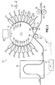
- Fig. 1 is a diagrammatic illustration of a multiple print head offset ink jet printing apparatus that utilizes the apparatus and method of the present invention.
- Fig. 2 is an enlarged diagrammatic illustration of the transfer of the inked image from the liquid intermediate transfer surface to a final receiving substrate.
- Fig. 3 is a diagrammatic illustration of the secondary fusing operation of the present invention showing the final receiving substrate passing through the fusing nip.
- Fig. 1 is a schematic illustration of a multiple print head, offset or indirect ink jet printing apparatus 10 that utilizes the secondary fusing method and apparatus of the present invention.
- the printing apparatus 10 is more fully disclosed in copending European Patent Application No (not yet assigned; attorney reference APEP98048) entitled PHASE CHANGE INK PRINTING ARCHITECTURE SUITABLE FOR HIGH SPEED IMAGING and assigned to the assignee of the present application. This Application is hereby specifically incorporated by reference in pertinent part.
- the imaging apparatus 10 in Fig. 1 utilizes an offset printing process to place a plurality of ink drops in imagewise fashion on a final receiving substrate.
- the apparatus 10 includes 16 print head modules 12A - 12N, 12P and 12Q positioned around a support surface or drum 14.
- the print head modules jet drops of ink 23, 25 in a molten or liquid state onto an intermediate transfer surface 9 on the drum 14.
- the intermediate transfer surface 9 is preferably a liquid layer that is applied to the drum 14 by contacting the drum with an applicator assembly 16 (See Fig. 1).
- Suitable liquids that may be used as the intermediate transfer surface include water, fluorinated oils, glycol, surfactants, mineral oil, silicone oil, functional oils and combinations thereof.
- the preferred liquid is amino silicone oil.
- the applicator assembly 16 includes a reservoir 18, a wicking pad 20 for applying the liquid and a metering blade 22 for consistently metering the liquid on the surface of the drum 14.
- Wicking pad 20 is preferably formed from any appropriate nonwoven synthetic textile with a relatively smooth surface.
- a preferred configuration can employ the smooth wicking pad 20 mounted atop a porous supporting material, such as a polyester felt. Both materials are available from BMP Corporation as BMP products NR 90 and PE 1100-UL, respectively.
- the metering blade meters the liquid to have a thickness of from about 0.025 microns to about 60 microns, and more preferably from about 0.05 to about 10 microns.
- the reservoir 18 may also be supplied by a separate liquid supply system (not shown) to insure an uninterrupted supply of liquid.
- the support surface may take the form of a drum 14 as shown in Fig. 1, or alternatively may be a belt, web, platen, or other suitable design.
- the support surface 14 may be formed from any appropriate material, such as metals including, but not limited to, aluminum, nickel or iron phosphate, elastomers, including but not limited to, fluoroelastomers, per fluoroelastomers, silicone rubber and polybutadiene, plastics, including but not limited to, polytetrafluoroethylene loaded with polyphenylene sulfide, thermoplastics such as polyethylene, nylon, arid FEP thermosets such as acetals or ceramics.
- the preferred material is anodized aluminum.
- liquid or molten ink is ejected from the print head modules 12A - 12N, 12P and 12Q onto the intermediate transfer surface 9 on the drum 14 to form an ink image thereon.
- a final receiving substrate or media 11 is fed through a preheater 30 and into a transfer nip 32 formed between the drum 14 and a transfer roller 34.
- the preheater 30 preheats the media 11 to a temperature of between about 50° C to about 100° C and preferably to about 70° C.
- the transfer roller 34 has a metallic core, preferably steel, with an elastomeric covering 15 having a 40 - 45 Shore D rating (see Fig. 2).
- Suitable elastomeric covering materials include silicones, urethanes, nitriles, EPDM and other appropriately resilient materials.
- the elastomeric covering 15 on roller 34 engages the media 11 on the side opposite to the side to which the ink image is transferred from the exposed surface of the intermediate transfer surface 9. As explained in more detail below, as the media 11 passes through the nip 32, it is pressed against the deposited ink image to transfer the ink image to the media.
- FIG. 2 diagrammatically illustrates the sequence involved when drops of ink 23, 25, 27 and 29 forming a portion of the ink image are transferred to the final receiving substrate 11.
- the drum 14 and the transfer roller 34 have a length of about 14 inches (35 cm.), and the width of the transfer nip is between about 0.020 in. (0.508 mm.) and about 0.140 inch (3.553 mm.), and more preferably between about 0.070 in.
- the force urging the transfer roller 34 into contact with the drum 14 is between about 100 lbf. (445 N.) and about 800 lbf. (3558 N.), and preferably about 700 lbf. (3114 N.).
- the preferred nip pressure is about 556 psi (3.83 X 10 6 Pa.).
- the liquid intermediate transfer surface 9 on the surface of drum 14 and the ink image deposited thereon are maintained within a predetermined temperature range by an appropriate heater device 28.
- Heater device 28 may be a radiant heater positioned as shown or, alternatively, positioned internally within the drum 14. Heater device 28 increases the temperature of the drum 14/ liquid intermediate transfer surface 9 from ambient temperature to between about 25° C and about 100° C or higher. This temperature is dependent upon the exact nature of the liquid employed in the intermediate transfer surface 9, the composition of the ink forming the ink image and other parameters of the printing process. Using amino silicone oil as the intermediate transfer surface and the preferred ink described below, a more preferred temperature range for the drum 14/liquid intermediate transfer surface 9 is between about 45° C to about 90° C, with the most preferable temperature being about 65° C.
- a phase change ink is utilized in the printing apparatus 10.
- the phase change ink is initially in solid form and is then changed to a molten state by the application of heat energy to raise the temperature to between about 85° C and about 150° C.
- the molten ink is then applied in raster fashion from the nozzles 42 in the print head modules 12A-12N, 12P and 12Q to the exposed surface of the liquid intermediate transfer surface 9.
- the ink cools to an intermediate temperature and solidifies to a malleable state in which it is transferred to the final receiving substrate 11 via the transfer nip 32.
- This intermediate temperature where the ink is maintained in its malleable state is between about 30° C and about 80° C, and preferably about 65° C.
- the ink used to form the ink image preferably has fluidic and mechanical properties that meet the parameters needed for high speed indirect printing at speeds of 100 ppm and higher.
- the viscosity of the ink in a molten state must be matched to the requirements of the print head modules utilized to apply it to the intermediate transfer surface 9.
- the viscosity of the molten ink must also be optimized relative to other physical and rheological properties of the ink as a solid, such as yield strength, hardness, elastic modulus, loss modulus, ratio of the loss modulus to the elastic modulus, and ductility.
- the hardening time required for the molten ink drops on the intermediate transfer surface 9/drum 14 to reach a malleable state suitable for transfer must be sufficiently short to support the desired printing speed.
- a preferred phase change ink is comprised of a phase change ink carrier composition admixed with a phase change ink compatible colorant. More specifically, the preferred phase change ink carrier composition comprises an admixture of (1) at least one urethane resin; and/or (2) at least one mixed urethane/urea resin; and (3) at least one mono-amide; and (4) at least one polyethylene wax.
- the preferred phase change ink carrier composition comprises an admixture of (1) at least one urethane resin; and/or (2) at least one mixed urethane/urea resin; and (3) at least one mono-amide; and (4) at least one polyethylene wax.
- phase change inks having various compositions may be utilized with the printing apparatus 10 in practicing the method and apparatus of the present invention as described herein.
- suitable alternative phase change inks are described in U.S. Patent Nos. 4,889,560 (the '560 patent) and 5,372,852 (the '852 patent).
- the '560 patent and '852 patent are hereby specifically incorporated by reference in pertinent part.
- the inks disclosed in these patents consist of a phase change ink carrier composition
- a phase change ink carrier composition comprising one or more fatty amide-containing materials, preferably consisting of a mono-amide wax and a tetra-amide resin, one or more tackifiers, one or more plasticizers and one or more antioxidants, in combination with compatible colorants.
- the ink image is fused into the media by passing the media through a secondary fusing nip 39 downstream from the transfer nip.
- the media 11 and ink image are first heated by a fusing preheater 50 to a temperature of between about 50° C and about 100° C, and more preferably to between about 65° C and about 70° C. The media 11 then passes through the secondary fusing nip 39.
- the secondary fusing nip 39 is formed by a first fuser roller 36 and a second fuser roller 38.
- First and second radiant heaters 37, 41 are used to maintain the first and second fuser rollers 36, 38, respectively, within a predetermined temperature range.
- First and second IR thermocouples 35, 55 monitor the temperature of the first and second fuser rollers 36, 38, respectively.
- the first and second fuser rollers 36, 38 are maintained between about 50° C and about 100° C, and more preferably between about 65° C and about 70° C.
- the first fuser roller 36 is driven to rotate at the same speed as the drum 14.
- the first fuser roller 36 is fabricated from a metal, such as steel, to provide a sufficiently hard contact area within the fusing nip 39.
- the second fuser roller 38 is a passive roller that is driven by contact with the powered first fuser roller 36.
- the second fuser roller 38 includes a hard inner core 52 and an elastomeric outer layer 54 having a durometer of about 85 Shore A.
- the outer elastomeric layer 54 gives the second fuser roller 38 a measure of compliance and allows for the creation of a wider fusing nip 39, as described below.
- Suitable elastomeric covering materials include silicones, urethanes, nitriles, EPDM and other appropriately resilient materials.
- the second fuser roller 38 is biased into contact with the first fuser roller 36 to create the fusing nip 39.
- each end of the second fuser roller 38 is attached to a moving linkage that is actuated by two pneumatic cylinders.
- a portion 56 of the linkage and a pneumatic cylinder 58 are schematically shown in Fig. 3. It will be appreciated that other means for biasing the second fuser roller 38 into contact with the first fuser roller 36 may be utilized, including, but not limited to, solenoids, motors and hydraulic cylinders.
- the pressure and temperature in the secondary fusing nip 39 combines with the pressure and temperature in the transfer nip 32 to fuse the ink image into the media 11 and achieve an improved ink pile height in the final image.
- the force urging the second fusing roller 38 into contact with the first fusing roller 36 is between about 400 lbf (1779 N.) and about 2000 lbf (8896 N.), and is preferably about 720 lbf. (3203 N.).
- the preferred width of the fusing nip 39 is between about 0.035 in. (0.888 mm.) and about 0.150 in. (3.807 mm.), and more preferably between about 0.085 in.
- the first and second fusing rollers 36, 38 have a preferred length of about 14 in. (35 cm.).
- the preferred nip pressure is about 605 psi (4.17 X 10 6 Pa.).
- the fusing preheater 50 heats the media 11 and ink image to a preferred temperature of between about 65° C and about 70° C.
- the speed of the media 11 through the transfer nip 32 and secondary fusing nip 39 is preferably about 15 in./sec. (ips) (38 mm./sec.).
- the preferred combination of the pressures, temperatures and media speed recited above allow the secondary fusing nip 39 to fuse the ink image into the media 11 to achieve an ink pile height of about 7 x 10 -4 in. (0.0178 mm.) or less. It has been observed that images having ink pile heights of 7 x 10 -4 in.
- images having ink pile heights of 7 x 10 -4 inch and less embody improved writability and travel more effectively through an automatic document feeder.
- utilizing separate nips for transferring and fusing the ink image allows the transfer nip to utilize a lower pressure and temperature.
- a lower pressure within the transfer nip 32 less force is exerted by the transfer roller 34 on the drum 14 during the imaging process. This reduces the possibility of the transfer roller 34 introducing position errors resulting in misalignment between the drum 14 and the print head modules 12A-12N, 12P and 12Q, particularly in the Y-axis direction.
- the present invention allows for greater consistency in image quality.
- This advantage is especially important in printing systems that image, transfer and fuse simultaneously and continuously, such as the apparatus 10 described in the present application. In these systems the drum 14 is under constant load from the transfer roller 34, and reducing the load on the drum substantially reduces wear on the drum components and the power required to rotate the drum.
- a release agent may be applied to the first fuser roller to prevent the ink image from adhering to the first fuser roller.
- the release agent is applied by contacting the first fuser roller with a liquid impregnated surface.
Abstract

Description
- This invention relates generally to an apparatus and method for image fusing in an ink jet printing system and, more specifically, to an apparatus and method that utilize separate image transfer and image fusing operations for improved fusing of an ink image into media.
- Ink jet printing involves ejecting ink droplets from orifices in a print head onto a receiving surface to form an image. The image is made up of a grid-like pattern of potential drop locations, commonly referred to as pixels. The resolution of the image is expressed by the number of ink drops or dots per inch (dpi), with common resolutions being 300 dpi and 600dpi.
- Ink-jet printing systems commonly utilize either direct printing or offset printing architecture. In a typical direct printing system, ink is ejected from jets in the print head directly onto the final receiving substrate. In an offset printing system, the image is formed on an intermediate transfer surface and subsequently transferred to the final receiving substrate. The intermediate transfer surface may take the form of a liquid layer that is applied to a support surface, such as a drum. The print head jets the ink onto the intermediate transfer surface to form an ink image thereon. Once the ink image has been fully deposited, the final receiving substrate is then brought into contact with the intermediate transfer surface and the ink image is transferred to the final receiving substrate.
- U.S. Patent 5,389,958 entitled IMAGING PROCESS and assigned to the assignee of the present application (the '958 patent) is an example of an indirect or offset printing architecture that utilizes phase change ink. The intermediate transfer surface is applied by a wicking pad that is housed within an applicator apparatus. Prior to imaging, the applicator is raised into contact with the rotating drum to apply or replenish the liquid intermediate transfer surface.
- Once the liquid intermediate transfer surface has been applied, the applicator is retracted and the print head ejects drops of ink to form the ink image on the liquid intermediate transfer surface. The ink is applied in molten form, having been melted from its solid state form. The ink image solidifies on the liquid intermediate transfer surface by cooling to a malleable solid intermediate state as the drum continues to rotate. When the imaging has been completed, a transfer roller is moved into contact with the drum to form a pressurized transfer nip between the roller and the curved surface of the intermediate transfer surface/drum. A final receiving substrate, such as a sheet of media, is then fed into the transfer nip and the ink image is transferred to the final receiving substrate.
- To provide acceptable image transfer and final image quality, an appropriate combination of pressure and temperature must be applied to the ink image on the final receiving substrate. US Patent No 5,777,650 entitled PRESSURE ROLLER and assigned to the assignee of the present application discloses a roller for fixing an ink image on a final receiving substrate. The preferred embodiment of the roller is described in the context of an offset ink jet printing apparatus similar to the one described in the '958 patent. In this embodiment, the final receiving medium is preheated to a preferred temperature of about 63° C and the pressure in the transfer nip is preferably about 1150 psi (7,929 kPa). Additionally, the speed of the final receiving medium through the transfer nip is approximately five inches/sec. (13cm./sec.).
- In a color printing system, the ink image on the final receiving surface is composed of individual drops of ink that form primary and secondary colors. The primary and/or secondary colors may include two or more drops of ink placed on top of one another. In the image transfer process, the ink image is transferred from the drum to the final receiving substrate. A portion of the ink image is fused or pressed into the final receiving substrate. The height of the remaining ink that lays above the surface of the final receiving substrate is referred to as the "ink pile height."
- The ink pile height of an image affects the "look and feel" of the image. In general, a lower ink pile height is preferred, as the appearance of the image will more closely resemble an image created by a commercial web press. The ink pile height also affects the ability of a user to write on the image. In images having ink pile heights approaching 1 x 10⁻³ in., and higher, the tip of a writing instrument will often furrow through the ink "pile." This can hinder the flow of writing ink through a ball point pen, or prevent the graphite writing surface of a pencil from contacting and marking the receiving substrate. Additionally, depending upon the composition of the ink used in the printer, ink pile height can hinder media from being transported through an automatic document feeder in a photocopier.
- In the prior art offset phase change ink printers, such as the printer described in the '958 patent, the ink pile height of images on the final receiving surface ranges from about 1 x 10⁻⁵ inch for a single pixel primary color to about 1 x 10⁻³ in. for a solid fill secondary color. By comparison, a liquid ink jet printer using a direct printing process and an aqueous-based ink produces images having a negligible ink pile height of less than 1 x 10⁻⁵ inch.
- In the image transfer process described above for the '958 patent, higher temperatures and pressures in the transfer process will generally yield lower ink pile heights. However, higher pressures in the transfer process also increase the loadings on the pressure roller, support surface or drum and other printer components. This accelerates wear on these components and tends to limit the maximum printing speed of the apparatus. Increased nip temperatures can inhibit duplex printing and cause the ink image to partially liquify and smear. These undesirable effects are magnified in an offset printing system in which the image transfer process is performed continuously; that is, the support surface or drum is under continuous loading and a high nip temperature is maintained. Thus, a need remains for an image fusing system that reduces ink image pile height, allows faster print speeds, reduces the transfer nip pressure and overcomes the other drawbacks of the prior art.
- It is an aspect of the present invention to provide an apparatus and related method for image fusing in an ink jet printing system.
- It is another aspect of the present invention that the apparatus and method utilize separate image transfer and fusing operations for improved fusing of an ink image into media.
- It is a feature of the present invention that the apparatus and method allow faster print speeds by utilizing separate image transfer and fusing operations.
- It is another feature of the present invention that the fusing operation may be utilized to apply a coating to the final receiving substrate.
- It is yet another feature of the present invention that the apparatus and method are capable of producing images having an ink pile height of 7 x 10⁻⁴ inch and less.
- It is an advantage of the present invention that the apparatus and method reduce the loading on the drum and transfer roller by using lower pressures in the image transfer operation.
- It is another advantage of the present invention that the apparatus and method are capable of reducing the ink pile height in images for better image durability and improved writability.
- To achieve the foregoing and other aspects, features and advantages, and in accordance with the purposes of the present invention as described herein, an apparatus and related method for improved image fusing in an ink jet printing system are provided. An ink image is transferred to a final receiving substrate by passing the substrate through a transfer nip. The substrate and ink image are then passed through a fusing nip that fuses the ink image into the final receiving substrate. By utilizing separate image transfer and fusing operations, improved image fusing is possible without compromising print speed. The secondary fusing operation enables the image transfer process to use reduced pressures, whereby the load on the drum and transfer roller is reduced. Additionally, the secondary fusing operation may be utilized to apply a supplemental coating to the transferred image.
- Nip pressures that may be utilised in the image transfer step are generally less than about 13.79 x 10⁶ Pa (2000psi), preferably less than about 5.52 x 10⁶ Pa (800psi), more preferably about 69 x 103 Pa (10 psi) to about 4.83 x 10⁶ Pa (700 psi), still more preferably about 689 x 103 Pa (100 psi) to 4.14 x 10⁶ Pa (600 psi), and most preferably about 1.38 x 10⁶ Pa (200 psi) to about 4.14 x 10⁶ Pa (600psi)
- Nip pressures that may be utilised in the image fusing step are generally less than about 27.58 x 10⁶ Pa (4000psi), preferably about 2.76 x 10⁶ Pa (400psi) to about 13.79 x 10⁶ Pa (2000psi), more preferably about 3.45 x 10⁶ Pa (500psi) to about 6.89 x 10⁶ Pa (1000psi), and most preferably about 4.14 x 10⁶ Pa (600psi) to about 6.89 x 10⁶ Pa (1000 psi).
- The following description is intended to illustrate the invention, by way of example only, reference being made to the accompanying drawings in which:
- Fig. 1 is a diagrammatic illustration of a multiple print head offset ink jet printing apparatus that utilizes the apparatus and method of the present invention.
- Fig. 2 is an enlarged diagrammatic illustration of the transfer of the inked image from the liquid intermediate transfer surface to a final receiving substrate.
- Fig. 3 is a diagrammatic illustration of the secondary fusing operation of the present invention showing the final receiving substrate passing through the fusing nip.
- Fig. 1 is a schematic illustration of a multiple print head, offset or indirect ink
jet printing apparatus 10 that utilizes the secondary fusing method and apparatus of the present invention. Theprinting apparatus 10 is more fully disclosed in copending European Patent Application No (not yet assigned; attorney reference APEP98048) entitled PHASE CHANGE INK PRINTING ARCHITECTURE SUITABLE FOR HIGH SPEED IMAGING and assigned to the assignee of the present application. This Application is hereby specifically incorporated by reference in pertinent part. - The following description of a preferred embodiment of the fusing method and apparatus of the present invention refers to its use in this type of printing apparatus. It will be appreciated, however, that the method and apparatus of the present invention may be used with various other printing apparatus that utilize different imaging technologies and/or architectures, such as direct ink jet printing in which ink drops are ejected directly onto a receiving substrate. Accordingly, the following description will be regarded as merely illustrative of one embodiment of the present invention.
- The
imaging apparatus 10 in Fig. 1 utilizes an offset printing process to place a plurality of ink drops in imagewise fashion on a final receiving substrate. In the preferred embodiment, theapparatus 10 includes 16print head modules 12A - 12N, 12P and 12Q positioned around a support surface ordrum 14. With reference now to Fig. 2, the print head modules jet drops ofink intermediate transfer surface 9 on thedrum 14. Theintermediate transfer surface 9 is preferably a liquid layer that is applied to thedrum 14 by contacting the drum with an applicator assembly 16 (See Fig. 1). Suitable liquids that may be used as the intermediate transfer surface include water, fluorinated oils, glycol, surfactants, mineral oil, silicone oil, functional oils and combinations thereof. The preferred liquid is amino silicone oil. - As shown in Fig. 1, the
applicator assembly 16 includes areservoir 18, awicking pad 20 for applying the liquid and ametering blade 22 for consistently metering the liquid on the surface of thedrum 14. Wickingpad 20 is preferably formed from any appropriate nonwoven synthetic textile with a relatively smooth surface. A preferred configuration can employ thesmooth wicking pad 20 mounted atop a porous supporting material, such as a polyester felt. Both materials are available from BMP Corporation as BMP products NR 90 and PE 1100-UL, respectively. The metering blade meters the liquid to have a thickness of from about 0.025 microns to about 60 microns, and more preferably from about 0.05 to about 10 microns. To allow continuous imaging and printing, thewicking pad 20 andblade 22 are continuously in contact with thedrum 14. Thereservoir 18 may also be supplied by a separate liquid supply system (not shown) to insure an uninterrupted supply of liquid. - The support surface may take the form of a
drum 14 as shown in Fig. 1, or alternatively may be a belt, web, platen, or other suitable design. Thesupport surface 14 may be formed from any appropriate material, such as metals including, but not limited to, aluminum, nickel or iron phosphate, elastomers, including but not limited to, fluoroelastomers, per fluoroelastomers, silicone rubber and polybutadiene, plastics, including but not limited to, polytetrafluoroethylene loaded with polyphenylene sulfide, thermoplastics such as polyethylene, nylon, arid FEP thermosets such as acetals or ceramics. The preferred material is anodized aluminum. - With continued reference to Figs. 1 and 2, liquid or molten ink is ejected from the
print head modules 12A - 12N, 12P and 12Q onto theintermediate transfer surface 9 on thedrum 14 to form an ink image thereon. A final receiving substrate ormedia 11 is fed through apreheater 30 and into a transfer nip 32 formed between thedrum 14 and atransfer roller 34. Thepreheater 30 preheats themedia 11 to a temperature of between about 50° C to about 100° C and preferably to about 70° C. In the preferred embodiment, thetransfer roller 34 has a metallic core, preferably steel, with anelastomeric covering 15 having a 40 - 45 Shore D rating (see Fig. 2). Suitable elastomeric covering materials include silicones, urethanes, nitriles, EPDM and other appropriately resilient materials. With reference now to Fig. 2, the elastomeric covering 15 onroller 34 engages themedia 11 on the side opposite to the side to which the ink image is transferred from the exposed surface of theintermediate transfer surface 9. As explained in more detail below, as themedia 11 passes through thenip 32, it is pressed against the deposited ink image to transfer the ink image to the media. - The pressure exerted on the ink image/
media 11 within the transfer nip 32, in combination with the temperature of the ink image andmedia 11 and the residence time of the media within the nip, should be sufficient to insure that the ink image is fully transferred to themedia 11. Figure 2 diagrammatically illustrates the sequence involved when drops ofink final receiving substrate 11. In the preferred embodiment, thedrum 14 and thetransfer roller 34 have a length of about 14 inches (35 cm.), and the width of the transfer nip is between about 0.020 in. (0.508 mm.) and about 0.140 inch (3.553 mm.), and more preferably between about 0.070 in. (1.777 mm) and about 0.090 inch (2.28 mm.). The force urging thetransfer roller 34 into contact with thedrum 14 is between about 100 lbf. (445 N.) and about 800 lbf. (3558 N.), and preferably about 700 lbf. (3114 N.). Thus, for a transfer nip width of 0.090 in. (2.28 mm.), the preferred nip pressure is about 556 psi (3.83 X 10⁶ Pa.). - With reference now to Figure 1, the liquid
intermediate transfer surface 9 on the surface ofdrum 14 and the ink image deposited thereon are maintained within a predetermined temperature range by anappropriate heater device 28.Heater device 28 may be a radiant heater positioned as shown or, alternatively, positioned internally within thedrum 14.Heater device 28 increases the temperature of thedrum 14/ liquidintermediate transfer surface 9 from ambient temperature to between about 25° C and about 100° C or higher. This temperature is dependent upon the exact nature of the liquid employed in theintermediate transfer surface 9, the composition of the ink forming the ink image and other parameters of the printing process. Using amino silicone oil as the intermediate transfer surface and the preferred ink described below, a more preferred temperature range for thedrum 14/liquidintermediate transfer surface 9 is between about 45° C to about 90° C, with the most preferable temperature being about 65° C. - In the preferred embodiment, a phase change ink is utilized in the
printing apparatus 10. The phase change ink is initially in solid form and is then changed to a molten state by the application of heat energy to raise the temperature to between about 85° C and about 150° C. The molten ink is then applied in raster fashion from the nozzles 42 in theprint head modules 12A-12N, 12P and 12Q to the exposed surface of the liquidintermediate transfer surface 9. The ink cools to an intermediate temperature and solidifies to a malleable state in which it is transferred to thefinal receiving substrate 11 via the transfer nip 32. This intermediate temperature where the ink is maintained in its malleable state is between about 30° C and about 80° C, and preferably about 65° C. - The ink used to form the ink image preferably has fluidic and mechanical properties that meet the parameters needed for high speed indirect printing at speeds of 100 ppm and higher. In particular, the viscosity of the ink in a molten state must be matched to the requirements of the print head modules utilized to apply it to the
intermediate transfer surface 9. The viscosity of the molten ink must also be optimized relative to other physical and rheological properties of the ink as a solid, such as yield strength, hardness, elastic modulus, loss modulus, ratio of the loss modulus to the elastic modulus, and ductility. Additionally, the hardening time required for the molten ink drops on theintermediate transfer surface 9/drum 14 to reach a malleable state suitable for transfer must be sufficiently short to support the desired printing speed. - A preferred phase change ink is comprised of a phase change ink carrier composition admixed with a phase change ink compatible colorant. More specifically, the preferred phase change ink carrier composition comprises an admixture of (1) at least one urethane resin; and/or (2) at least one mixed urethane/urea resin; and (3) at least one mono-amide; and (4) at least one polyethylene wax. A more detailed description of the preferred phase change ink is found in European Patent Application No 99 300521.4.
- This application is hereby specifically incorporated by reference in pertinent part.
- It will be appreciated that many other types of phase change inks having various compositions may be utilized with the
printing apparatus 10 in practicing the method and apparatus of the present invention as described herein. Examples of suitable alternative phase change inks are described in U.S. Patent Nos. 4,889,560 (the '560 patent) and 5,372,852 (the '852 patent). The '560 patent and '852 patent are hereby specifically incorporated by reference in pertinent part. The inks disclosed in these patents consist of a phase change ink carrier composition comprising one or more fatty amide-containing materials, preferably consisting of a mono-amide wax and a tetra-amide resin, one or more tackifiers, one or more plasticizers and one or more antioxidants, in combination with compatible colorants. - Returning to Fig. 1 and in an important aspect of the present invention, after the
media 11 passes through the transfer nip 32 and the ink image is transferred to the media, the ink image is fused into the media by passing the media through a secondary fusing nip 39 downstream from the transfer nip. With reference now to Fig. 3, after passing through the transfer nip 32, themedia 11 and ink image are first heated by a fusingpreheater 50 to a temperature of between about 50° C and about 100° C, and more preferably to between about 65° C and about 70° C. Themedia 11 then passes through the secondary fusing nip 39. - The secondary fusing nip 39 is formed by a
first fuser roller 36 and asecond fuser roller 38. First and secondradiant heaters second fuser rollers second IR thermocouples second fuser rollers second fuser rollers - The
first fuser roller 36 is driven to rotate at the same speed as thedrum 14. In the preferred embodiment, thefirst fuser roller 36 is fabricated from a metal, such as steel, to provide a sufficiently hard contact area within the fusing nip 39. Thesecond fuser roller 38 is a passive roller that is driven by contact with the poweredfirst fuser roller 36. Preferably, thesecond fuser roller 38 includes a hardinner core 52 and an elastomericouter layer 54 having a durometer of about 85 Shore A. The outerelastomeric layer 54 gives the second fuser roller 38 a measure of compliance and allows for the creation of a wider fusing nip 39, as described below. Suitable elastomeric covering materials include silicones, urethanes, nitriles, EPDM and other appropriately resilient materials. - The
second fuser roller 38 is biased into contact with thefirst fuser roller 36 to create the fusing nip 39. In the preferred embodiment, each end of thesecond fuser roller 38 is attached to a moving linkage that is actuated by two pneumatic cylinders. Aportion 56 of the linkage and apneumatic cylinder 58 are schematically shown in Fig. 3. It will be appreciated that other means for biasing thesecond fuser roller 38 into contact with thefirst fuser roller 36 may be utilized, including, but not limited to, solenoids, motors and hydraulic cylinders. - In an important aspect of the present invention, the pressure and temperature in the secondary fusing nip 39 combines with the pressure and temperature in the transfer nip 32 to fuse the ink image into the
media 11 and achieve an improved ink pile height in the final image. In the preferred embodiment, the force urging thesecond fusing roller 38 into contact with thefirst fusing roller 36 is between about 400 lbf (1779 N.) and about 2000 lbf (8896 N.), and is preferably about 720 lbf. (3203 N.). The preferred width of the fusing nip 39 is between about 0.035 in. (0.888 mm.) and about 0.150 in. (3.807 mm.), and more preferably between about 0.085 in. (2.157 mm.) and about 0.100 in. (2.538 mm.). The first andsecond fusing rollers - As described above, the fusing
preheater 50 heats themedia 11 and ink image to a preferred temperature of between about 65° C and about 70° C. In the preferred operation of theprinting apparatus 10, the speed of themedia 11 through the transfer nip 32 and secondary fusing nip 39 is preferably about 15 in./sec. (ips) (38 mm./sec.). Advantageously, and in an important aspect of the present invention, the preferred combination of the pressures, temperatures and media speed recited above allow the secondary fusing nip 39 to fuse the ink image into themedia 11 to achieve an ink pile height of about 7 x 10⁻⁴ in. (0.0178 mm.) or less. It has been observed that images having ink pile heights of 7 x 10⁻⁴ in. and less have an improved appearance as compared with images from prior art ink jet printers that produce ink pile heights of greater than 7 x 10⁻⁴ in. Additionally, images having ink pile heights of 7 x 10⁻⁴ inch and less embody improved writability and travel more effectively through an automatic document feeder. - In another important advantage of the present invention, utilizing separate nips for transferring and fusing the ink image allows the transfer nip to utilize a lower pressure and temperature. Advantageously, by utilizing a lower pressure within the transfer nip 32, less force is exerted by the
transfer roller 34 on thedrum 14 during the imaging process. This reduces the possibility of thetransfer roller 34 introducing position errors resulting in misalignment between thedrum 14 and theprint head modules 12A-12N, 12P and 12Q, particularly in the Y-axis direction. In this manner, the present invention allows for greater consistency in image quality. This advantage is especially important in printing systems that image, transfer and fuse simultaneously and continuously, such as theapparatus 10 described in the present application. In these systems thedrum 14 is under constant load from thetransfer roller 34, and reducing the load on the drum substantially reduces wear on the drum components and the power required to rotate the drum. - While the invention has been described above with references to specific embodiments thereof, it is apparent that many changes, modifications and variations in the materials, arrangements of parts and steps can be made without departing from the inventive concept disclosed herein. For example, while the preferred embodiment is described in connection with a multiple print head ink jet printer that utilizes phase change ink, it is to be understood that the invention may be practiced with other ink jet printing architectures and with other types of inks, such as aqueous-based and solvent-based inks.
- A release agent may be applied to the first fuser roller to prevent the ink image from adhering to the first fuser roller. Preferably, the release agent is applied by contacting the first fuser roller with a liquid impregnated surface.
- Using the method and apparatus of the present invention, it is also possible to apply a coating to the final receiving substrate when it passes through the second nip.
Claims (25)
- A method of offset printing in an ink jet printer (10), the method comprising the steps of:(a) forming an ink image on a preliminary receiving surface (9);(b) passing a final receiving substrate (11) through a first nip (32) where it comes into contact with the preliminary receiving surface (9);(c) exerting a first pressure on the final receiving substrate (11) in the first nip (32) to transfer the ink image from the preliminary receiving surface (9) to the final receiving substrate (11);(d) passing the final receiving substrate (11) through a second nip (39); and(e) exerting a second pressure on the final receiving substrate (11) in the second nip (39) to fuse the ink image into the final receiving substrate (11).
- A method as claimed in claim 1 wherein the pressure exerted on the final receiving substrate (11) in the second nip (39) is sufficient to achieve an ink pile height of about 0.0178mm (0.0007inch) or less.
- A method as claimed in claim 1 or claim 2 wherein the pressure exerted on the final receiving substrate (11) in the first nip (32) is less than about 5.52 x 10⁶ Pa (800 psi).
- A method as claim in any preceding claim wherein the pressure exerted on the final receiving substrate (11) in the second nip (39) is between about 2.76 x 10⁶ Pa (400 psi) and about 13.79 x 10⁶ Pa (2000 psi).
- A method as claimed in any preceding claim wherein the final receiving substrate (11) is preheated to a temperature of between about 50°C and about 100°C before it is passed through the first nip (32).
- A method as claimed in any preceding claim wherein the final receiving substrate (11) is heated to a temperature of between about 50°C and about 100°C after the ink image is transferred to the final receiving substrate (11) and prior to passing the final receiving substrate (11) through the second nip (39).
- A method as claimed in any preceding claim wherein the step of passing the final receiving substrate (11) through a first nip (32) comprises the step of passing the final receiving substrate between the preliminary receiving surface (9) and a transfer roller (34).
- A method as claimed in any preceding claim wherein the step of passing the final receiving substrate (11) through a second nip (39) comprises the step of passing the final receiving substrate (11) between a first fuser roller (36) and a second fuser roller (38).
- A method as claimed in claim 8 wherein the second fuser roller (38) has an elastomeric outer layer (54).
- A method as claimed in claim 8 or claim 9 wherein the first fuser roller (36) has a metallic outer surface.
- A method as claimed in any of claims 8 to 10 further including the step of applying a release agent to the first fuser roller (36) to prevent the ink image from adhering to the first fuser roller (36).
- A method as claimed in claim 11 wherein the step of applying a release agent to the first fuser roller (36) further comprises the step of contacting the first fuser roller (36) with a liquid impregnated surface.
- A method as claimed in any of claims 8 to 12 further including the step of maintaining the first fuser roller (36) at a temperature of between about 50°C and about 100°C.
- A method as claimed in any preceding claim wherein the step of passing the final receiving substrate (11) through a second nip (39) further comprises the step of applying a coating to the final receiving substrate (11) in the second nip (39).
- An ink jet printing system (10) for forming an ink image on a final receiving substrate (11) comprising:a print head (12) for ejecting drops of ink onto a preliminary receiving surface (9) to form an ink image thereon;a first nip (32) formed by the preliminary receiving surface (9) and an opposing surface, the first nip (32) receiving the final receiving substrate (11) and exerting a first pressure on the final receiving substrate (11) to transfer the ink image to the final receiving substrate (11); anda second nip (39) for receiving the final receiving substrate (11) after the final receiving substrate (11) passes through the first nip (32), the second nip (39), exerting a second pressure on the final receiving substrate to fuse the ink image into the final receiving substrate (11).
- An ink jet printing system as claimed in claim 15 wherein the pressure exerted on the final receiving substrate (11) in the second nip (39) is sufficient to achieve an ink pile height of about 0.0178mm (0.0007 inch) or less.
- An ink jet printing system (10) as claimed in claim 15 or claim 16 wherein the pressure exerted on the final receiving substrate (11) in the second nip (39) is between about 2.76 x 10⁶ Pa (400 psi) and about 13.79 x 10⁶ Pa (2000 psi).
- An ink jet printing system (10) as claimed in any of claims 15 to 17 wherein the pressure exerted on the final receiving substrate (11) in the first nip (32) is less than about 5.52 x 10⁶ Pa (800 psi).
- An ink jet printing system as claimed in any of claims 15 to 18 further including a media heater (50) between the first nip (32) and the second nip (39) for heating the final receiving substrate (11) to a temperature of between about 50°C and about 100°C prior to the final receiving substrate (11) entering the second nip (39).
- An ink jet printing system (10) as claimed in any of claims 15 to 19 wherein the second nip (39) comprises a first fuser roller (36) and a second fuser roller (38), the second fuser roller (38) being biased into contact with the first fuser roller (36).
- An ink jet printing system (10) as claimed in claim 20 wherein the first fuser roller (36) has a metallic outer surface.
- An ink jet printing system (20) as claimed in claim 21 wherein the second fuser roller (38) has an elastomeric outer layer (54) forming an outer surface.
- An ink jet printing system as claimed in any of claims 20 to 22 further comprising an applicator in contact with the outer surface of the first fuser roller (36), the applicator applying a coating to the outer surface of the first fuser roller (36).
- An ink jet printing system (10) as claimed in claim 23 wherein the coating comprises a release agent for preventing the ink image from adhering to the outer surface of the first fuser roller (36).
- An ink jet printing system (10) as claimed in any of claims 20 to 24 further comprising a roller heater (37) for maintaining the first fuser roller (36) at a temperature of between about 50°C and about 100°C.
Applications Claiming Priority (6)
| Application Number | Priority Date | Filing Date | Title |
|---|---|---|---|
| US62521 | 1987-06-12 | ||
| US30672 | 1998-02-25 | ||
| US09/030,672 US6213580B1 (en) | 1998-02-25 | 1998-02-25 | Apparatus and method for automatically aligning print heads |
| US09/045,216 US6113231A (en) | 1998-02-25 | 1998-03-19 | Phase change ink printing architecture suitable for high speed imaging |
| US09/062,521 US6196675B1 (en) | 1998-02-25 | 1998-04-17 | Apparatus and method for image fusing |
| US45216 | 2001-11-07 |
Publications (3)
| Publication Number | Publication Date |
|---|---|
| EP0938975A2 true EP0938975A2 (en) | 1999-09-01 |
| EP0938975A3 EP0938975A3 (en) | 2000-02-23 |
| EP0938975B1 EP0938975B1 (en) | 2007-12-19 |
Family
ID=27363692
Family Applications (1)
| Application Number | Title | Priority Date | Filing Date |
|---|---|---|---|
| EP99301400A Expired - Lifetime EP0938975B1 (en) | 1998-02-25 | 1999-02-25 | Apparatus and method for image fusing |
Country Status (2)
| Country | Link |
|---|---|
| EP (1) | EP0938975B1 (en) |
| DE (1) | DE69937767T2 (en) |
Cited By (3)
| Publication number | Priority date | Publication date | Assignee | Title |
|---|---|---|---|---|
| NL1021010C2 (en) * | 2002-07-05 | 2004-01-06 | Oce Tech Bv | Method for printing a receiving material with hot melt ink and an inkjet printer suitable for applying this method. |
| US7419230B2 (en) | 2002-03-29 | 2008-09-02 | Olympus Corporation | Test chart geometrical characteristic analysis system geometrical characteristic analysis method printer and ink-jet printer |
| BE1017612A5 (en) * | 2005-12-16 | 2009-02-03 | Manroland Ag | INKJET PRINTING DEVICE. |
Citations (4)
| Publication number | Priority date | Publication date | Assignee | Title |
|---|---|---|---|---|
| US4889560A (en) | 1988-08-03 | 1989-12-26 | Tektronix, Inc. | Phase change ink composition and phase change ink produced therefrom |
| US5372852A (en) | 1992-11-25 | 1994-12-13 | Tektronix, Inc. | Indirect printing process for applying selective phase change ink compositions to substrates |
| US5389958A (en) | 1992-11-25 | 1995-02-14 | Tektronix, Inc. | Imaging process |
| US5777650A (en) | 1996-11-06 | 1998-07-07 | Tektronix, Inc. | Pressure roller |
Family Cites Families (4)
| Publication number | Priority date | Publication date | Assignee | Title |
|---|---|---|---|---|
| JPH04239653A (en) * | 1991-01-24 | 1992-08-27 | Matsushita Electric Ind Co Ltd | Thermal transfer recording method and apparatus |
| JP2778331B2 (en) * | 1992-01-29 | 1998-07-23 | 富士ゼロックス株式会社 | Ink jet recording device |
| WO1994001283A1 (en) * | 1992-07-02 | 1994-01-20 | Seiko Epson Corporation | Intermediate transfer type ink jet recording method |
| US5805191A (en) * | 1992-11-25 | 1998-09-08 | Tektronix, Inc. | Intermediate transfer surface application system |
-
1999
- 1999-02-25 DE DE69937767T patent/DE69937767T2/en not_active Expired - Lifetime
- 1999-02-25 EP EP99301400A patent/EP0938975B1/en not_active Expired - Lifetime
Patent Citations (4)
| Publication number | Priority date | Publication date | Assignee | Title |
|---|---|---|---|---|
| US4889560A (en) | 1988-08-03 | 1989-12-26 | Tektronix, Inc. | Phase change ink composition and phase change ink produced therefrom |
| US5372852A (en) | 1992-11-25 | 1994-12-13 | Tektronix, Inc. | Indirect printing process for applying selective phase change ink compositions to substrates |
| US5389958A (en) | 1992-11-25 | 1995-02-14 | Tektronix, Inc. | Imaging process |
| US5777650A (en) | 1996-11-06 | 1998-07-07 | Tektronix, Inc. | Pressure roller |
Cited By (5)
| Publication number | Priority date | Publication date | Assignee | Title |
|---|---|---|---|---|
| US7419230B2 (en) | 2002-03-29 | 2008-09-02 | Olympus Corporation | Test chart geometrical characteristic analysis system geometrical characteristic analysis method printer and ink-jet printer |
| NL1021010C2 (en) * | 2002-07-05 | 2004-01-06 | Oce Tech Bv | Method for printing a receiving material with hot melt ink and an inkjet printer suitable for applying this method. |
| EP1378357A1 (en) * | 2002-07-05 | 2004-01-07 | Océ-Technologies B.V. | A method of printing a receiving material with hot melt ink and an inkjet printer suitable for applying this method |
| US6905203B2 (en) | 2002-07-05 | 2005-06-14 | Océ-Technologies B.V. | Method of printing a receiving material with hot melt ink and an inkjet printer suitable for applying such a method |
| BE1017612A5 (en) * | 2005-12-16 | 2009-02-03 | Manroland Ag | INKJET PRINTING DEVICE. |
Also Published As
| Publication number | Publication date |
|---|---|
| EP0938975A3 (en) | 2000-02-23 |
| EP0938975B1 (en) | 2007-12-19 |
| DE69937767T2 (en) | 2008-04-30 |
| DE69937767D1 (en) | 2008-01-31 |
Similar Documents
| Publication | Publication Date | Title |
|---|---|---|
| US6196675B1 (en) | Apparatus and method for image fusing | |
| EP0938974B1 (en) | Phase change ink printing architecture suitable for high speed imaging | |
| US5777650A (en) | Pressure roller | |
| US7322689B2 (en) | Phase change ink transfix pressure component with dual-layer configuration | |
| US7828423B2 (en) | Ink-jet printer using phase-change ink printing on a continuous web | |
| US7407278B2 (en) | Phase change ink transfix pressure component with single layer configuration | |
| US6494570B1 (en) | Controlling gloss in an offset ink jet printer | |
| US5389958A (en) | Imaging process | |
| EP0694388B1 (en) | Method and apparatus for controlling phase-change ink jet print quality factors | |
| US7682014B2 (en) | Apparatus for media preheating in an ink jet printer | |
| US7874664B2 (en) | Electrically conductive pressure roll surfaces for phase-change ink-jet printer for direct on paper printing | |
| US20090141110A1 (en) | Ink-jet printer using phase-change ink for direct on paper printing | |
| US20090142112A1 (en) | Phase change ink imaging component having composite outer layer | |
| US7325917B2 (en) | Phase change ink transfix pressure component with three-layer configuration | |
| EP0604025B1 (en) | Imaging process | |
| JP2005096468A (en) | Offset printing method for ink jet printer, and ink jet printer | |
| US5821956A (en) | Method to improve solid ink output resolution | |
| EP0938975B1 (en) | Apparatus and method for image fusing | |
| US7401912B2 (en) | Phase change ink imaging component with thermoset layer | |
| US6527386B1 (en) | Compliant imaging surface for offset printing | |
| US8337009B2 (en) | Method for skewing printer transfix roll | |
| US7845783B2 (en) | Pressure roller two-layer coating for phase-change ink-jet printer for direct on paper printing | |
| JPH11334057A (en) | Ink jet printer and offset printing method thereby | |
| JP2552110B2 (en) | Inkjet recording device | |
| US7014897B2 (en) | Imaging member having a textured imaging surface and a phase change ink image producing machine having same |
Legal Events
| Date | Code | Title | Description |
|---|---|---|---|
| PUAI | Public reference made under article 153(3) epc to a published international application that has entered the european phase |
Free format text: ORIGINAL CODE: 0009012 |
|
| AK | Designated contracting states |
Kind code of ref document: A2 Designated state(s): DE FR GB NL |
|
| AX | Request for extension of the european patent |
Free format text: AL;LT;LV;MK;RO;SI |
|
| RAP1 | Party data changed (applicant data changed or rights of an application transferred) |
Owner name: TEKTRONIX, INC. |
|
| PUAL | Search report despatched |
Free format text: ORIGINAL CODE: 0009013 |
|
| AK | Designated contracting states |
Kind code of ref document: A3 Designated state(s): AT BE CH CY DE DK ES FI FR GB GR IE IT LI LU MC NL PT SE |
|
| AX | Request for extension of the european patent |
Free format text: AL;LT;LV;MK;RO;SI |
|
| RIC1 | Information provided on ipc code assigned before grant |
Free format text: 7B 41J 2/01 A, 7B 41J 2/005 B |
|
| RAP1 | Party data changed (applicant data changed or rights of an application transferred) |
Owner name: XEROX CORPORATION |
|
| 17P | Request for examination filed |
Effective date: 20000823 |
|
| AKX | Designation fees paid |
Free format text: DE FR GB NL |
|
| 17Q | First examination report despatched |
Effective date: 20040604 |
|
| GRAP | Despatch of communication of intention to grant a patent |
Free format text: ORIGINAL CODE: EPIDOSNIGR1 |
|
| GRAS | Grant fee paid |
Free format text: ORIGINAL CODE: EPIDOSNIGR3 |
|
| GRAA | (expected) grant |
Free format text: ORIGINAL CODE: 0009210 |
|
| AK | Designated contracting states |
Kind code of ref document: B1 Designated state(s): DE FR GB NL |
|
| REG | Reference to a national code |
Ref country code: GB Ref legal event code: FG4D |
|
| REF | Corresponds to: |
Ref document number: 69937767 Country of ref document: DE Date of ref document: 20080131 Kind code of ref document: P |
|
| ET | Fr: translation filed | ||
| PLBE | No opposition filed within time limit |
Free format text: ORIGINAL CODE: 0009261 |
|
| STAA | Information on the status of an ep patent application or granted ep patent |
Free format text: STATUS: NO OPPOSITION FILED WITHIN TIME LIMIT |
|
| 26N | No opposition filed |
Effective date: 20080922 |
|
| PGFP | Annual fee paid to national office [announced via postgrant information from national office to epo] |
Ref country code: NL Payment date: 20120217 Year of fee payment: 14 |
|
| REG | Reference to a national code |
Ref country code: NL Ref legal event code: V1 Effective date: 20130901 |
|
| PG25 | Lapsed in a contracting state [announced via postgrant information from national office to epo] |
Ref country code: NL Free format text: LAPSE BECAUSE OF NON-PAYMENT OF DUE FEES Effective date: 20130901 |
|
| PGFP | Annual fee paid to national office [announced via postgrant information from national office to epo] |
Ref country code: DE Payment date: 20140122 Year of fee payment: 16 |
|
| PGFP | Annual fee paid to national office [announced via postgrant information from national office to epo] |
Ref country code: FR Payment date: 20140221 Year of fee payment: 16 |
|
| PGFP | Annual fee paid to national office [announced via postgrant information from national office to epo] |
Ref country code: GB Payment date: 20140127 Year of fee payment: 16 |
|
| REG | Reference to a national code |
Ref country code: DE Ref legal event code: R119 Ref document number: 69937767 Country of ref document: DE |
|
| GBPC | Gb: european patent ceased through non-payment of renewal fee |
Effective date: 20150225 |
|
| REG | Reference to a national code |
Ref country code: FR Ref legal event code: ST Effective date: 20151030 |
|
| PG25 | Lapsed in a contracting state [announced via postgrant information from national office to epo] |
Ref country code: DE Free format text: LAPSE BECAUSE OF NON-PAYMENT OF DUE FEES Effective date: 20150901 Ref country code: GB Free format text: LAPSE BECAUSE OF NON-PAYMENT OF DUE FEES Effective date: 20150225 |
|
| PG25 | Lapsed in a contracting state [announced via postgrant information from national office to epo] |
Ref country code: FR Free format text: LAPSE BECAUSE OF NON-PAYMENT OF DUE FEES Effective date: 20150302 |