EP0938276B1 - Vascular filter - Google Patents
Vascular filter Download PDFInfo
- Publication number
- EP0938276B1 EP0938276B1 EP98903877A EP98903877A EP0938276B1 EP 0938276 B1 EP0938276 B1 EP 0938276B1 EP 98903877 A EP98903877 A EP 98903877A EP 98903877 A EP98903877 A EP 98903877A EP 0938276 B1 EP0938276 B1 EP 0938276B1
- Authority
- EP
- European Patent Office
- Prior art keywords
- filter membrane
- guidewire
- filter
- vascular
- fibers
- Prior art date
- Legal status (The legal status is an assumption and is not a legal conclusion. Google has not performed a legal analysis and makes no representation as to the accuracy of the status listed.)
- Expired - Lifetime
Links
Images


Classifications
-
- A—HUMAN NECESSITIES
- A61—MEDICAL OR VETERINARY SCIENCE; HYGIENE
- A61F—FILTERS IMPLANTABLE INTO BLOOD VESSELS; PROSTHESES; DEVICES PROVIDING PATENCY TO, OR PREVENTING COLLAPSING OF, TUBULAR STRUCTURES OF THE BODY, e.g. STENTS; ORTHOPAEDIC, NURSING OR CONTRACEPTIVE DEVICES; FOMENTATION; TREATMENT OR PROTECTION OF EYES OR EARS; BANDAGES, DRESSINGS OR ABSORBENT PADS; FIRST-AID KITS
- A61F2/00—Filters implantable into blood vessels; Prostheses, i.e. artificial substitutes or replacements for parts of the body; Appliances for connecting them with the body; Devices providing patency to, or preventing collapsing of, tubular structures of the body, e.g. stents
- A61F2/01—Filters implantable into blood vessels
- A61F2/0108—Both ends closed, i.e. legs gathered at both ends
-
- A—HUMAN NECESSITIES
- A61—MEDICAL OR VETERINARY SCIENCE; HYGIENE
- A61F—FILTERS IMPLANTABLE INTO BLOOD VESSELS; PROSTHESES; DEVICES PROVIDING PATENCY TO, OR PREVENTING COLLAPSING OF, TUBULAR STRUCTURES OF THE BODY, e.g. STENTS; ORTHOPAEDIC, NURSING OR CONTRACEPTIVE DEVICES; FOMENTATION; TREATMENT OR PROTECTION OF EYES OR EARS; BANDAGES, DRESSINGS OR ABSORBENT PADS; FIRST-AID KITS
- A61F2/00—Filters implantable into blood vessels; Prostheses, i.e. artificial substitutes or replacements for parts of the body; Appliances for connecting them with the body; Devices providing patency to, or preventing collapsing of, tubular structures of the body, e.g. stents
- A61F2/01—Filters implantable into blood vessels
- A61F2/0105—Open ended, i.e. legs gathered only at one side
-
- A—HUMAN NECESSITIES
- A61—MEDICAL OR VETERINARY SCIENCE; HYGIENE
- A61F—FILTERS IMPLANTABLE INTO BLOOD VESSELS; PROSTHESES; DEVICES PROVIDING PATENCY TO, OR PREVENTING COLLAPSING OF, TUBULAR STRUCTURES OF THE BODY, e.g. STENTS; ORTHOPAEDIC, NURSING OR CONTRACEPTIVE DEVICES; FOMENTATION; TREATMENT OR PROTECTION OF EYES OR EARS; BANDAGES, DRESSINGS OR ABSORBENT PADS; FIRST-AID KITS
- A61F2/00—Filters implantable into blood vessels; Prostheses, i.e. artificial substitutes or replacements for parts of the body; Appliances for connecting them with the body; Devices providing patency to, or preventing collapsing of, tubular structures of the body, e.g. stents
- A61F2/01—Filters implantable into blood vessels
- A61F2/013—Distal protection devices, i.e. devices placed distally in combination with another endovascular procedure, e.g. angioplasty or stenting
-
- A—HUMAN NECESSITIES
- A61—MEDICAL OR VETERINARY SCIENCE; HYGIENE
- A61B—DIAGNOSIS; SURGERY; IDENTIFICATION
- A61B17/00—Surgical instruments, devices or methods, e.g. tourniquets
- A61B17/22—Implements for squeezing-off ulcers or the like on the inside of inner organs of the body; Implements for scraping-out cavities of body organs, e.g. bones; Calculus removers; Calculus smashing apparatus; Apparatus for removing obstructions in blood vessels, not otherwise provided for
-
- A—HUMAN NECESSITIES
- A61—MEDICAL OR VETERINARY SCIENCE; HYGIENE
- A61F—FILTERS IMPLANTABLE INTO BLOOD VESSELS; PROSTHESES; DEVICES PROVIDING PATENCY TO, OR PREVENTING COLLAPSING OF, TUBULAR STRUCTURES OF THE BODY, e.g. STENTS; ORTHOPAEDIC, NURSING OR CONTRACEPTIVE DEVICES; FOMENTATION; TREATMENT OR PROTECTION OF EYES OR EARS; BANDAGES, DRESSINGS OR ABSORBENT PADS; FIRST-AID KITS
- A61F2/00—Filters implantable into blood vessels; Prostheses, i.e. artificial substitutes or replacements for parts of the body; Appliances for connecting them with the body; Devices providing patency to, or preventing collapsing of, tubular structures of the body, e.g. stents
- A61F2/01—Filters implantable into blood vessels
- A61F2/011—Instruments for their placement or removal
-
- A—HUMAN NECESSITIES
- A61—MEDICAL OR VETERINARY SCIENCE; HYGIENE
- A61F—FILTERS IMPLANTABLE INTO BLOOD VESSELS; PROSTHESES; DEVICES PROVIDING PATENCY TO, OR PREVENTING COLLAPSING OF, TUBULAR STRUCTURES OF THE BODY, e.g. STENTS; ORTHOPAEDIC, NURSING OR CONTRACEPTIVE DEVICES; FOMENTATION; TREATMENT OR PROTECTION OF EYES OR EARS; BANDAGES, DRESSINGS OR ABSORBENT PADS; FIRST-AID KITS
- A61F2/00—Filters implantable into blood vessels; Prostheses, i.e. artificial substitutes or replacements for parts of the body; Appliances for connecting them with the body; Devices providing patency to, or preventing collapsing of, tubular structures of the body, e.g. stents
- A61F2/01—Filters implantable into blood vessels
- A61F2002/018—Filters implantable into blood vessels made from tubes or sheets of material, e.g. by etching or laser-cutting
-
- A—HUMAN NECESSITIES
- A61—MEDICAL OR VETERINARY SCIENCE; HYGIENE
- A61F—FILTERS IMPLANTABLE INTO BLOOD VESSELS; PROSTHESES; DEVICES PROVIDING PATENCY TO, OR PREVENTING COLLAPSING OF, TUBULAR STRUCTURES OF THE BODY, e.g. STENTS; ORTHOPAEDIC, NURSING OR CONTRACEPTIVE DEVICES; FOMENTATION; TREATMENT OR PROTECTION OF EYES OR EARS; BANDAGES, DRESSINGS OR ABSORBENT PADS; FIRST-AID KITS
- A61F2230/00—Geometry of prostheses classified in groups A61F2/00 - A61F2/26 or A61F2/82 or A61F9/00 or A61F11/00 or subgroups thereof
- A61F2230/0002—Two-dimensional shapes, e.g. cross-sections
- A61F2230/0004—Rounded shapes, e.g. with rounded corners
- A61F2230/0006—Rounded shapes, e.g. with rounded corners circular
-
- A—HUMAN NECESSITIES
- A61—MEDICAL OR VETERINARY SCIENCE; HYGIENE
- A61F—FILTERS IMPLANTABLE INTO BLOOD VESSELS; PROSTHESES; DEVICES PROVIDING PATENCY TO, OR PREVENTING COLLAPSING OF, TUBULAR STRUCTURES OF THE BODY, e.g. STENTS; ORTHOPAEDIC, NURSING OR CONTRACEPTIVE DEVICES; FOMENTATION; TREATMENT OR PROTECTION OF EYES OR EARS; BANDAGES, DRESSINGS OR ABSORBENT PADS; FIRST-AID KITS
- A61F2230/00—Geometry of prostheses classified in groups A61F2/00 - A61F2/26 or A61F2/82 or A61F9/00 or A61F11/00 or subgroups thereof
- A61F2230/0063—Three-dimensional shapes
- A61F2230/0067—Three-dimensional shapes conical
-
- A—HUMAN NECESSITIES
- A61—MEDICAL OR VETERINARY SCIENCE; HYGIENE
- A61F—FILTERS IMPLANTABLE INTO BLOOD VESSELS; PROSTHESES; DEVICES PROVIDING PATENCY TO, OR PREVENTING COLLAPSING OF, TUBULAR STRUCTURES OF THE BODY, e.g. STENTS; ORTHOPAEDIC, NURSING OR CONTRACEPTIVE DEVICES; FOMENTATION; TREATMENT OR PROTECTION OF EYES OR EARS; BANDAGES, DRESSINGS OR ABSORBENT PADS; FIRST-AID KITS
- A61F2230/00—Geometry of prostheses classified in groups A61F2/00 - A61F2/26 or A61F2/82 or A61F9/00 or A61F11/00 or subgroups thereof
- A61F2230/0063—Three-dimensional shapes
- A61F2230/0093—Umbrella-shaped, e.g. mushroom-shaped
Definitions
- the present invention relates to a vascular filter device according to the pre-characterising portion of claim 1.
- a vascular filter device is known from US-A-4 723 549.
- Balloon angioplasty utilizes a balloon-tipped catheter which may be inserted within a stenosed region of the blood vessel. By inflation of the balloon, the stenosed region is dilated.
- Surgery involves either removing the plaque from the artery or attaching a graft to the artery so as to bypass the obstructing plaque.
- Other techniques, such as atherectomy have also been proposed. In atherectomy, a rotating blade is used to shave plaque from an arterial wall.
- emboli which can lodge elsewhere in the vascular system.
- emboli are, of course, extremely dangerous to the patient, frequently causing severe impairment of the distal circulatory bed. Depending upon the vessel being treated, this may result in a stroke or myocardial infarction or limb ischemia.
- Vascular filters or embolism traps for implantation into the vena cava of a patient are well known, being illustrated by, for example, U.S. Patents. Nos. 4,727,873 and 4,688,553. Additionally, there is a substantial amount of medical literature describing various designs of vascular filters and reporting the results of the clinical and experimented use thereof. See, for example, the article by Eichelter & Schenk entitled “Prophylaxis of Pulmonary Embolism," Archives of Surgery, Vol. 97, August 1968, pp. 348 et seq. See, also, the article by Greenfield, et al., entitled “A New Intracaval Filter Permitting Continued flow and Resolution of Emboli", Surgery, vol. 73, No. 4, pp. 599-606 (1973).
- Vascular filters are used, often during a postoperative period, when there is a perceived risk of a patient encountering a pulmonary embolus resulting from clots generated at the surgical site or the like.
- the filter is mounted in the vena cava to catch large emboli passing from the surgical site to the lungs.
- U.S. Pat. No. 4,723,549 teaches a catheter for dilating occluded or stenotic blood vessels including a collapsible filter device disposed between a dilatation balloon and the distal end of the catheter.
- the inflation of the dilatation balloon serves to expand the collapsible filter and the reverse action of resilient ribs in the filter member serves to retract the filter upon deflation of the balloon.
- U.S. Pat. No. 5,053,008 teaches a multi-sheathed catheter with umbrella filter positioned on its exterior sheath, which is specifically sized to fit a patient's pulmonary artery and a means for biasing the umbrella to an open position.
- the therein described suffers from having a low flexibility. Moreover, there is no recess in the catheter.
- SU-A-764 684 discloses a catheter having a filter attached to a complicated umbrella-like mechanism.
- vascular filters of the prior art are usually permanently implanted in the venous system of the patient, so that even after the need for the filter has abated, the filter remains in place for the lifetime of the patient, absent surgical removal.
- U.S. Pat. No. 3,952,747 describes a stainless steel filtering device which is permanently implanted transvenously within the inferior vena cava. The filtering device is intended to treat recurrent pulmonary embolism.
- U.S. Pat. No. 4,873,978 describes a catheter device comprising a catheter body having a strainer mounted at it distal end. The strainer is shiftable between an opened configuration where it extends substantially across the blood vessel to entrap passing emboli, and a closed configuration where it retains the captured emboli during removal of the catheter.
- a mechanism actuable at the proximate end of the catheter body allows selective opening and closing of the strainer.
- the strainer is a collapsible cone having an apex attached to a wire running from the distal end to the proximate end of the catheter body.
- Permanent implantation is often deemed medically undesirable, but it has been done because vascular filters are implanted in patients primarily in response to potentially life threatening situations. Accordingly, the disadvantages of permanent implantations of a vascular filter are often accepted.
- the present invention generally relates to the surgical and interventional treatment of vascular disease.
- vascular disease For example, during angioplasty and stenting of carotid stenosis, there is occurrence of macro- and micro-embolism, which increases the risk of a minor or major stroke.
- the object to be solved by the device of the present invention is to prevent the risk of stroke.
- Another object is to present embolization, a risk in any angioplasty or surgical procedure.
- vascular filter device as initially defined, wherein it further comprises the features of the characterising portion of claim 1.
- the filters of the present invention will decrease embolism while allowing brain, or other distal tissue, perfusion.
- the filters are incorporated into a guidewire which is used for the entire procedure from crossing a lesion to deploying a stent.
- the filter consists of a thin membrane attached to the guidewire and supported by fine metal spines.
- the filter membrane has a pore size such that blood flow is not impeded when the filter membrane is expanded but micro- and macro-emboli are blocked.
- the attachments of the filter membrane to the guidewire allow expansion of the filter membrane with a firm fit inside the artery. Expansion of the filter membrane is aided by the forward flow of blood against the filter.
- the attachments also allow for collapse of the filter membrane at the end of the procedure so it fits tightly against the guidewire and can be withdrawn through the guide catheter.
- the filter design results in a very low profile so that the initial crossing of the lesion is minimally traumatic. Also, the small diameter and small profile facilitate use of the device in small or larger arteries with minimal or no obstruction of blood flow.
- the present invention relates to a vascular filter for use in percutaneous angioplasty and stenting and provides for the prevention of distal embolism during endovascular procedures. Further, the filter device of the invention allows for distal perfusion while preventing embolism.
- the device consists of a thin, perforated filter membrane which is capable of blocking emboli and which is attached to the distal end of a guidewire.
- the device preferably uses thin fibers which are moveable and are attached to the filter membrane to deploy and collapse the filter membrane.
- the invention also contemplates the use of metal spines or inflatable spines attached to the filter membrane to deploy the filter membrane.
- the fibers or spines can also be attached to a moveable core which is slidable within the guidewire and is used to deploy and collapse the filter membrane.
- the filter membrane deploys in an umbrella-like fashion with the unattached edge of the membrane moving upward, i.e., distally, and outward until it is in firm contact with an artery wall.
- the filter membrane When the filter membrane is deployed, it spans the cross-sectional area of the vessel lumen being treated for a stenosis such as carotid stenosis, or another condition likely to produce emboli.
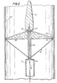
- Fig. 1 illustrates a lateral, cross-sectional view of a distal end of a guidewire 10 with a filter membrane 20 attached thereto.
- Fig. 1 shows guidewire 10 with a shapeable, tapered soft tip 15 at its extreme distal end which provides flexibility and maneuverability to guidewire 10.
- the filter membrane in Fig. 1 is in a collapsed position.
- Filter membrane 20 has a fixed portion 24 which is movably attached to guidewire 10, and filter membrane 20 lies adjacent guidewire 10 proximal to fixed portion 24 when filter membrane 20 is in the collapsed state.
- a moveable core 40 runs through a center lumen 11 of guidewire 10 and preferably extends distally a short distance beyond fixed portion 24 of filter membrane 20.
- Deploying wires or fibers 30 are each firmly attached at one end 27 to moveable core 40 distal to fixed portion 21 of filter membrane 20. The deploying fibers 30 are attached at their other ends to filter membrane 20 at attachment points 22.
- Collapsing fibers 35 are each firmly attached at one end 12 to the portion of moveable core wire 40 which is interior to filter membrane 20 when it is in the collapsed state. Collapsing fibers 35 are each attached at their other end 13 to filter membrane 20 at attachment points 22. Accordingly, collapsing fibers 35 lie interior to filter membrane 20 when filter membrane 20 is in the collapsed state.
- Filter membrane 20 is deployed when the operator pulls moveable core 40 proximally through the interior of guidewire 10. Prior to retraction of moveable core 40, deploying fibers 30 are sufficiently relaxed so as not to create any tension at filter membrane attachment points 22. Upon retraction of moveable core 40, tension is created in deploying fibers 30.
- the deploying fibers 30 and collapsing fibers 35 can be made of any flexible, medically acceptable material, including stainless steel, nitinol, or another metal or metallic alloy or a non-metallic substance such as graphite or a suitable polymer.
- guidewire 10 and moveable core 40 can be made from similar materials, as would be appreciated by those skilled in the art.
- guidewire 10 could have an external diameter of from about 0.014 mm to about 0.035 mm, a wall thickness of from about 0.002 mm to about 0.010 mm, and a length of from about 25 cm to about 300 cm.
- moveable core 40 could have a diameter of from about 0.003 mm to about 0.010 mm and a length of from about 30 cm to about 350 cm.
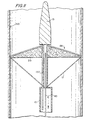
- Fig. 2 illustrates the filter device of the invention in a deployed position on the inside of an artery wall 60.
- Moveable core 40 is in a retracted state, i.e., pulled proximally through the interior of guidewire 10.
- Tension is created in deploying fibers 30, and filter membrane 20 extends to a deployed position where the outer edge 14 of filter membrane 20 contacts artery wall 60.
- collapsing fibers 35 are in a relaxed state and extend from filter membrane attachment points 22 to fixed attachment points 28 on moveable core 40.
- the flow of blood in Fig. 2 is toward the distal end of guidewire 10. As such, the force of the flow of blood pushes on deployed filter membrane 20 and helps to maintain filter membrane 20 in the deployed position.
- filter membrane 20 is collapsed so that it sits tightly against guidewire 10. This is accomplished by extending moveable core 40 distally through guidewire 10, thus relaxing deploying fibers 30 and creating tension in collapsing fibers 35. The tension in collapsing fibers 35 collapses the filter membrane 20, allowing it to fit tightly against guidewire 10 in recess 16 as depicted in FIG. 1.
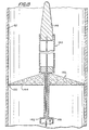
- Fig. 3 illustrates the filter device of the invention from a distal end view in Fig. 2 with filter membrane 20 deployed.
- Guidewire 10 is centrally located, and structural wires 50 are seen extending from guidewire 10 to the outer edge 14 of filter membrane 20. These wires 50 provide structural integrity and rigidity to filter membrane 20.
- Fig. 3 depicts four, evenly-spaced structural wires 50, but there can be more or less structural wires 50. Preferably there are from two to six structural wires 50, which may be spaced regularly or irregularly.
- the wires 50 may preferably be comprised of stainless steel or another medically acceptable metal or alloy.
- Filter membrane 20 of the invention is preferably a mesh such as that depicted in Fig. 3.
- the mesh should have pores of a size sufficient to block and capture any micro- and macro-emboli which may flow downstream from the site where the stenosis is being treated, but large enough such that blood flow is not impeded.
- the mesh used in the filter device of the invention can have a pore size of from about 20 to about 300 microns, preferably from about 30 to about 100 microns, more preferably from about 40 to 60 microns.
- the size of filter membrane 20, i.e., the distance from guidewire 10 to free ends 22, is such as to allow a firm fit between filter membrane 20 and artery wall 60.
- the diameter of filter membrane 20 will be directly related to the artery being treated, with typical diameters ranging from about 2 mm to about 40 mm, most preferably from about 2 mm to about 20 mm.
- the membrane can be comprised of fabric or non-fabric meshes, such as those used in known hemodialysis filters or heart-lung bypass machine filters. Suitable materials include polymers or physiologically acceptable metals or alloys.
- filter membrane 20 will be suspended between from two to six, preferably three or four, thin metal wires 51 which serve as spines for filter membrane 20.
- Wires 51 may be comprised of stainless steel or another metallic alloy, nitinol, or another shape-memory material. Wires 51 will be constructed so that they assume a 90° angle with guidewire 10 when they are in an unconstrained state. This will result in expansion of the filter membrane 20 to a position normal to guidewire 10.
- a set of thin fibers 17 are attached at attachment points 18 to filter membrane outer edge 14 and are used to collapse filter membrane 20.
- Fig. 4 shows an embodiment of this invention in which metal wires 51 are allowed to regain their 90° angle unconstrained state by use of a moveable core 40 that runs through guidewire 10.
- fibers 17 Prior to retraction of moveable core 40, fibers 17 are sufficiently tensed so as to restrain wires 51.
- tension in fibers 17 is released and wires 51 are allowed to revert to their relaxed shape, which will result in expansion of filter membrane 20 to a position normal to guidewire 10.
- Figs. 5A and 5B show an embodiment of the invention wherein wires 51 are restrained by fibers 17 that run through guidewire 10 and that are controlled at a remote location.
- Fig. 5A there is sufficient tension in fibers 17 to maintain wires 51 in a constrained position.
- Fig. 5B tension in fibers 17 has been relaxed such that wires 51 are allowed to revert to their relaxed shape, which will result in expansion of filter membrane 20 to a position normal to guidewire 10.
- Fig. 6 depicts a control handle especially suitable for the embodiment of the invention shown in Figs. 5A and 5B.
- the proximal end 32 of guidewire 10 is rotatably attached to handle 33, such that rotation of handle 33 causes handle 33 to move distally or proximally relative to proximal guidewire end 32.
- handle 33 may have threads 34 which engage threads 35 on guidewire proximal end 32.
- Fibers 17 attached to filter membrane 20 are secured in a base 36 of handle 33. Then, as handle 33 is turned, the fibers 17 move distally or proximally to open or close filter membrane 20.
- filter membrane 20 can be supported by inflatable spines 135 supporting the filter membrane 20.
- Spines 135 supporting the filter membrane 20 are from two to six hollow plastic tubes which are inflatable using, for example, a standard ballon angioplasty inflation device or endoflator in fluid connection through channel 137 with spines 135. Inflation of spines 135 causes them to become rigid and deploys filter membrane 20.
- the underside of the filter membrane is attached to very thin fibers 17 which are attached to moveable core 40 inside hollow guidewire 10.
- Filter membrane 20 is collapsed by deflating the spines 135 and withdrawing the moveable core 40 in the direction of arrow E until the membrane 20 fits tightly against guidewire 10.
- a catheter-based configuration is also possible, as shown in FIG. 7.
- the guidewire is not part of the filter catheter; the guidewire and filter catheter are two separate components.
- the filter catheter has an entry hole for the guidewire below the attachment of the filter membrane and the guidewire exits out the end of the filter catheter.
- the filter catheter could be designed to accommodate a variety of guidewire sizes, most commonly a 0.0356 cm (0.014 inch) guidewire. The advantages of this design are that a variety of guidewires could be used; the lesion could be crossed with the guidewire prior to crossing with the filter catheter; the filter catheter could be removed from the artery without removing the guidewire; and the filter catheter could be made smaller.
- a catheter 101 comprises a longitudinally extending lumen 103, which has an annular recess 105 adjacent the distal end of catheter 101.
- a filter 107 Positioned within recess 105 is a filter 107 comprised of structural wires 109 and a filter membrane 111. The distal end of each of wires 109 is attached at point 113 in recess 105. Fibers 117 extend from the proximal ends 119 of wires 109 proximally to a control means such as described in Fig. 6.
- Catheter 101 contains guidewire port 125 located proximal the recess 105. It is intended that in use the distal portion 128 of a guidewire 127 will be threaded into the distal end 129 of catheter 101 and out through port 125.
- a catheter 101 could comprise a longitudinally extending lumen and a shorter tracking lumen that extends from distal end 129 to a point proximal to recess 105. The distal end of guidewire 127 would then be threaded into the distal opening of the tracking lumen and out the proximal end of the tracking lumen.
- Spiral or curved structural wires may be used to deploy the filter membrane instead of straight wires.
- Fig. 8 illustrates the use of four curved wires 120.
- the angulation of the filter attachment point of wires 120 relative to their guidewire attachment has the effect of wrapping the filter fabric around the guidewire in the undeployed state. This leads to a lower profile for the undeployed filter.
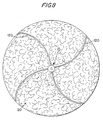
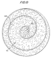
- Figs. 9 and 10 illustrate the use of a single spiral structural wire 130 which is attached to the filter 107.
- wire 130 unwinds and deploys filter 107 in a conical configuration.
- This configuration has the simplicity of using a single wire and, when the tension on the fiber 131 is increased, allows filter 107 to be wrapped very tightly around the guidewire shaft 131, resulting in filter 107 having a low profile in its undeployed state.
- FIG. 12 and 13 Another modification shown in Figs. 12 and 13 comprises a retractable sheath 140 at the distal end of guidewire 142 which covers filter membrane 144 in the collapsed state.
- Sheath 140 the distal portion of which is affixed to guidewire tip 146, which is affixed to the distal end of moveable core 148, would prevent an edge 150 of filter membrane 144 from becoming entangled in an artery or guide catheter as it was being withdrawn from a patient.
- sheath 140 covers collapsed filter membrane 144.
- moveable core 148 is pushed distally to cause sheath 140 to "release" filter membrane 144, which has spines 152, to cause filter membrane 144 to deploy, as shown in Fig. 13.
Description
| No. | |
| 10 | Guidewire |
| 11 | |
| 12 | End of collapsing |
| 13 | End of collapsing |
| 14 | Filter membrane |
| 15 | Guidewire |
| 17 | Collapsing |
| 18 | |
| 20 | |
| 22 | Filter |
| 24 | Filter membrane fixed |
| 27 | |
| 28 | |
| 30 | Deploying |
| 32 | Guidewire |
| 33 | |
| 34 | |
| 35 | Guidewire |
| 36 | |
| 40 | |
| 50 | Structural wires |
| 51 | Deploying |
| 60 | |
| 101 | Catheter |
| 103 | |
| 105 | |
| 107 | |
| 109 | Filter wire |
| 111 | |
| 113 | |
| 117 | |
| 120 | Curved filter |
| 125 | |
| 127 | |
| 128 | Guidewire |
| 129 | |
| 131 | |
| 132 | |
| 135 | |
| 137 | |
| 140 | |
| 142 | |
| 144 | |
| 146 | |
| 148 | |
| 150 | |
| 152 | Filter membrane spine |
Claims (11)
- A vascular filter device for blocking micro- and macro-emboli in a lumen of a relatively small diameter artery, while allowing continued perfusion of blood, comprising:a removable guidewire having distal and proximal portions,a filter membrane having a free outer portion,
and a fixed inner portion (24), wherein a deploying means (12) connected to the filter membrane is adapted to cause the filter membrane to move from a collapsed position wherein it is substantially parallel to the guidewire to an expanded position removed from the longitudinal axis of the guidewire to cause the filter membrane to form a substantially conical shape to form a sealing relationship with the wall of the vessel (Figs. 2, 5B, 7, 9, 11, 13) characterized in that there is a recess in the distal portion, the recess having distal and proximal ends, and the free outer portion of the filter membrane is positioned in the recess when the filter membrane is in a collapsed state (Figs. 1, 4, 5A ,12), the fixed inner portion is movably attached toward the distal end of the guidewire recess, the recess having a predetermined depth for providing space for the filter membrane. - A vascular filter according to Claim 1, wherein the guidewire is hollow and wherein the deploying means comprises a movable core (40), the movable core being slidably positioned in the interior of the guidewire.
- A vascular filter according to Claim 2, wherein the deploying means further comprises deploying fibers (30) each having first and second ends and said filter membrane further comprises an outer edge, and wherein said deploying fibers are each attached at a first end to a moveable core (40) and are attached at a second end to the outer edge of the filter membrane.
- A vascular filter according to Claim 2 or 3, wherein the movable core (40) is adapted to slide towards said proximal end during deployment, and the filter membrane is adapted to expand outwardly until the outer edge of the filter membrane is in firm contact with the lumen.
- A vascular filter according to any one of claims 2 to 4, wherein it comprises a collapsing means for collapsing the filter membrane from a deployed state to a collapsed state.
- A vascular filter according to Claim 5, wherein the collapsing means further comprises collapsing fibers (35) each having first and second ends, wherein said collapsing fibers are each attached at a first end to the movable core and are further attached at a second end to the outer edge of the filter membrane.
- A vascular filter according to Claim 5 or 6, wherein the movable core (40) is adapted to slide towards said distal end during collapsing, and the filter membrane is adapted to collapse tightly around the guidewire.
- A vascular filter according to any one of the preceding Claims, wherein the guidewire has a lumen extending distally from the proximal portion of the guidewire to at least the recess.
- A vascular filter according to any one of the preceding Claims, wherein the guidewire has a tapered distal tip.
- A vascular filter according to any one of the preceding Claims, wherein the filter membrane is comprised of a porous mesh.
- A vascular filter according to Claim 10, wherein the pore size of the porous mesh is from about 40 to about 300 microns.
Priority Applications (2)
| Application Number | Priority Date | Filing Date | Title |
|---|---|---|---|
| EP02006579A EP1226797B1 (en) | 1997-02-03 | 1998-02-03 | Vascular filter |
| EP02006578A EP1226796B1 (en) | 1997-02-03 | 1998-02-03 | Vascular filter |
Applications Claiming Priority (3)
| Application Number | Priority Date | Filing Date | Title |
|---|---|---|---|
| US79401197A | 1997-02-03 | 1997-02-03 | |
| US794011 | 1997-02-03 | ||
| PCT/US1998/001894 WO1998033443A1 (en) | 1997-02-03 | 1998-02-03 | Vascular filter |
Related Child Applications (2)
| Application Number | Title | Priority Date | Filing Date |
|---|---|---|---|
| EP02006578A Division EP1226796B1 (en) | 1997-02-03 | 1998-02-03 | Vascular filter |
| EP02006579A Division EP1226797B1 (en) | 1997-02-03 | 1998-02-03 | Vascular filter |
Publications (3)
| Publication Number | Publication Date |
|---|---|
| EP0938276A1 EP0938276A1 (en) | 1999-09-01 |
| EP0938276A4 EP0938276A4 (en) | 2000-04-19 |
| EP0938276B1 true EP0938276B1 (en) | 2003-08-13 |
Family
ID=25161414
Family Applications (3)
| Application Number | Title | Priority Date | Filing Date |
|---|---|---|---|
| EP02006578A Expired - Lifetime EP1226796B1 (en) | 1997-02-03 | 1998-02-03 | Vascular filter |
| EP02006579A Expired - Lifetime EP1226797B1 (en) | 1997-02-03 | 1998-02-03 | Vascular filter |
| EP98903877A Expired - Lifetime EP0938276B1 (en) | 1997-02-03 | 1998-02-03 | Vascular filter |
Family Applications Before (2)
| Application Number | Title | Priority Date | Filing Date |
|---|---|---|---|
| EP02006578A Expired - Lifetime EP1226796B1 (en) | 1997-02-03 | 1998-02-03 | Vascular filter |
| EP02006579A Expired - Lifetime EP1226797B1 (en) | 1997-02-03 | 1998-02-03 | Vascular filter |
Country Status (8)
| Country | Link |
|---|---|
| US (1) | US6755846B1 (en) |
| EP (3) | EP1226796B1 (en) |
| JP (2) | JP2000504263A (en) |
| AU (1) | AU742712B2 (en) |
| CA (1) | CA2250777C (en) |
| DE (3) | DE69830431T2 (en) |
| ES (3) | ES2245386T3 (en) |
| WO (1) | WO1998033443A1 (en) |
Families Citing this family (173)
| Publication number | Priority date | Publication date | Assignee | Title |
|---|---|---|---|---|
| US6736843B1 (en) | 1994-07-25 | 2004-05-18 | Advanced Cardiovascular Systems, Inc. | Cylindrically-shaped balloon-expandable stent |
| US5636641A (en) | 1994-07-25 | 1997-06-10 | Advanced Cardiovascular Systems, Inc. | High strength member for intracorporeal use |
| US6168604B1 (en) | 1995-10-06 | 2001-01-02 | Metamorphic Surgical Devices, Llc | Guide wire device for removing solid objects from body canals |
| US6544276B1 (en) | 1996-05-20 | 2003-04-08 | Medtronic Ave. Inc. | Exchange method for emboli containment |
| US6391044B1 (en) * | 1997-02-03 | 2002-05-21 | Angioguard, Inc. | Vascular filter system |
| EP0934092A4 (en) | 1997-03-06 | 2008-03-26 | Boston Scient Scimed Inc | Distal protection device and method |
| US5814064A (en) * | 1997-03-06 | 1998-09-29 | Scimed Life Systems, Inc. | Distal protection device |
| US6152946A (en) * | 1998-03-05 | 2000-11-28 | Scimed Life Systems, Inc. | Distal protection device and method |
| US5911734A (en) * | 1997-05-08 | 1999-06-15 | Embol-X, Inc. | Percutaneous catheter and guidewire having filter and medical device deployment capabilities |
| US6059814A (en) * | 1997-06-02 | 2000-05-09 | Medtronic Ave., Inc. | Filter for filtering fluid in a bodily passageway |
| US6761727B1 (en) | 1997-06-02 | 2004-07-13 | Medtronic Ave, Inc. | Filter assembly |
| US6461370B1 (en) | 1998-11-03 | 2002-10-08 | C. R. Bard, Inc. | Temporary vascular filter guide wire |
| BR9813935A (en) | 1997-11-07 | 2000-09-19 | Salviac Ltd | Vascular filtration devices for removing embolic material from body fluids |
| WO1999062432A1 (en) * | 1998-06-04 | 1999-12-09 | New York University | Endovascular thin film devices and methods for treating and preventing stroke |
| US7569062B1 (en) * | 1998-07-15 | 2009-08-04 | St. Jude Medical, Inc. | Mitral and tricuspid valve repair |
| US6231588B1 (en) | 1998-08-04 | 2001-05-15 | Percusurge, Inc. | Low profile catheter for angioplasty and occlusion |
| US7314477B1 (en) | 1998-09-25 | 2008-01-01 | C.R. Bard Inc. | Removable embolus blood clot filter and filter delivery unit |
| US20020138094A1 (en) * | 1999-02-12 | 2002-09-26 | Thomas Borillo | Vascular filter system |
| US6171327B1 (en) * | 1999-02-24 | 2001-01-09 | Scimed Life Systems, Inc. | Intravascular filter and method |
| AU3844799A (en) * | 1999-05-07 | 2000-11-21 | Salviac Limited | A filter element with retractable guidewire tip |
| AU3844199A (en) | 1999-05-07 | 2000-11-21 | Salviac Limited | An embolic protection device |
| WO2000067670A1 (en) * | 1999-05-07 | 2000-11-16 | Salviac Limited | An embolic protection device |
| FR2794653B1 (en) * | 1999-06-14 | 2001-12-21 | Sarl Aln | KIT FOR THE REMOVAL OF A BLADDER VESSEL FILTER OF THE UMBRELLA TYPE |
| US6203561B1 (en) | 1999-07-30 | 2001-03-20 | Incept Llc | Integrated vascular device having thrombectomy element and vascular filter and methods of use |
| US6544279B1 (en) | 2000-08-09 | 2003-04-08 | Incept, Llc | Vascular device for emboli, thrombus and foreign body removal and methods of use |
| US6530939B1 (en) * | 1999-07-30 | 2003-03-11 | Incept, Llc | Vascular device having articulation region and methods of use |
| US6179861B1 (en) | 1999-07-30 | 2001-01-30 | Incept Llc | Vascular device having one or more articulation regions and methods of use |
| CA2378715C (en) * | 1999-07-30 | 2011-09-06 | Incept Llc | Vascular device for emboli, thrombus and foreign body removal and methods of use |
| US6214026B1 (en) | 1999-07-30 | 2001-04-10 | Incept Llc | Delivery system for a vascular device with articulation region |
| US6346116B1 (en) | 1999-08-03 | 2002-02-12 | Medtronic Ave, Inc. | Distal protection device |
| US6142987A (en) * | 1999-08-03 | 2000-11-07 | Scimed Life Systems, Inc. | Guided filter with support wire and methods of use |
| FR2797390B1 (en) * | 1999-08-10 | 2001-12-28 | Braun Celsa Sa | DEVICE FOR TREATING A BODY DUCT THAT HAS AT LEAST ONE PARTIAL OBSTRUCTION |
| DE29916162U1 (en) | 1999-09-14 | 2000-01-13 | Cormedics Gmbh | Vascular filter system |
| US6264672B1 (en) | 1999-10-25 | 2001-07-24 | Biopsy Sciences, Llc | Emboli capturing device |
| US6217589B1 (en) | 1999-10-27 | 2001-04-17 | Scimed Life Systems, Inc. | Retrieval device made of precursor alloy cable and method of manufacturing |
| US6425909B1 (en) | 1999-11-04 | 2002-07-30 | Concentric Medical, Inc. | Methods and devices for filtering fluid flow through a body structure |
| US6575997B1 (en) | 1999-12-23 | 2003-06-10 | Endovascular Technologies, Inc. | Embolic basket |
| US6402771B1 (en) | 1999-12-23 | 2002-06-11 | Guidant Endovascular Solutions | Snare |
| US6660021B1 (en) | 1999-12-23 | 2003-12-09 | Advanced Cardiovascular Systems, Inc. | Intravascular device and system |
| US6406471B1 (en) * | 1999-12-28 | 2002-06-18 | Embol-X, Inc. | Arterial filter with aspiration and methods of use |
| US7918820B2 (en) | 1999-12-30 | 2011-04-05 | Advanced Cardiovascular Systems, Inc. | Device for, and method of, blocking emboli in vessels such as blood arteries |
| US6702834B1 (en) | 1999-12-30 | 2004-03-09 | Advanced Cardiovascular Systems, Inc. | Embolic protection devices |
| US6695813B1 (en) | 1999-12-30 | 2004-02-24 | Advanced Cardiovascular Systems, Inc. | Embolic protection devices |
| US6540768B1 (en) * | 2000-02-09 | 2003-04-01 | Cordis Corporation | Vascular filter system |
| GB2369575A (en) * | 2000-04-20 | 2002-06-05 | Salviac Ltd | An embolic protection system |
| US6602271B2 (en) | 2000-05-24 | 2003-08-05 | Medtronic Ave, Inc. | Collapsible blood filter with optimal braid geometry |
| US6645221B1 (en) | 2000-05-30 | 2003-11-11 | Zuli, Holdings Ltd. | Active arterial embolization filter |
| US6939362B2 (en) * | 2001-11-27 | 2005-09-06 | Advanced Cardiovascular Systems, Inc. | Offset proximal cage for embolic filtering devices |
| US6964670B1 (en) | 2000-07-13 | 2005-11-15 | Advanced Cardiovascular Systems, Inc. | Embolic protection guide wire |
| EP1172073A1 (en) * | 2000-07-13 | 2002-01-16 | Cordis Corporation | Vascular filter system with guidewire and capture mechanism |
| US6679902B1 (en) | 2000-07-19 | 2004-01-20 | Advanced Cardiovascular Systems, Inc. | Reduced profile delivery sheath for use in interventional procedures |
| US20020016597A1 (en) | 2000-08-02 | 2002-02-07 | Dwyer Clifford J. | Delivery apparatus for a self-expanding stent |
| US6485501B1 (en) | 2000-08-11 | 2002-11-26 | Cordis Corporation | Vascular filter system with guidewire and capture mechanism |
| US6558405B1 (en) | 2000-08-29 | 2003-05-06 | Advanced Cardiovascular Systems, Inc. | Embolic filter |
| US6511496B1 (en) | 2000-09-12 | 2003-01-28 | Advanced Cardiovascular Systems, Inc. | Embolic protection device for use in interventional procedures |
| US6616681B2 (en) * | 2000-10-05 | 2003-09-09 | Scimed Life Systems, Inc. | Filter delivery and retrieval device |
| US6537294B1 (en) | 2000-10-17 | 2003-03-25 | Advanced Cardiovascular Systems, Inc. | Delivery systems for embolic filter devices |
| US6893451B2 (en) | 2000-11-09 | 2005-05-17 | Advanced Cardiovascular Systems, Inc. | Apparatus for capturing objects beyond an operative site utilizing a capture device delivered on a medical guide wire |
| US6726703B2 (en) | 2000-11-27 | 2004-04-27 | Scimed Life Systems, Inc. | Distal protection device and method |
| US6506203B1 (en) | 2000-12-19 | 2003-01-14 | Advanced Cardiovascular Systems, Inc. | Low profile sheathless embolic protection system |
| US6663651B2 (en) | 2001-01-16 | 2003-12-16 | Incept Llc | Systems and methods for vascular filter retrieval |
| US6689151B2 (en) * | 2001-01-25 | 2004-02-10 | Scimed Life Systems, Inc. | Variable wall thickness for delivery sheath housing |
| US6840950B2 (en) * | 2001-02-20 | 2005-01-11 | Scimed Life Systems, Inc. | Low profile emboli capture device |
| US6569184B2 (en) | 2001-02-27 | 2003-05-27 | Advanced Cardiovascular Systems, Inc. | Recovery system for retrieving an embolic protection device |
| US6562058B2 (en) | 2001-03-02 | 2003-05-13 | Jacques Seguin | Intravascular filter system |
| US8182527B2 (en) | 2001-05-07 | 2012-05-22 | Cordis Corporation | Heparin barrier coating for controlled drug release |
| US20020188314A1 (en) * | 2001-06-07 | 2002-12-12 | Microvena Corporation | Radiopaque distal embolic protection device |
| US7780693B2 (en) * | 2001-06-27 | 2010-08-24 | Salviac Limited | Catheter |
| US7789860B2 (en) * | 2001-06-27 | 2010-09-07 | Salviac Limited | Catheter for delivery and/or retrieval of a medical device |
| US7338510B2 (en) | 2001-06-29 | 2008-03-04 | Advanced Cardiovascular Systems, Inc. | Variable thickness embolic filtering devices and method of manufacturing the same |
| US6599307B1 (en) | 2001-06-29 | 2003-07-29 | Advanced Cardiovascular Systems, Inc. | Filter device for embolic protection systems |
| US6962598B2 (en) * | 2001-07-02 | 2005-11-08 | Rubicon Medical, Inc. | Methods, systems, and devices for providing embolic protection |
| US6951570B2 (en) * | 2001-07-02 | 2005-10-04 | Rubicon Medical, Inc. | Methods, systems, and devices for deploying a filter from a filter device |
| US6878153B2 (en) | 2001-07-02 | 2005-04-12 | Rubicon Medical, Inc. | Methods, systems, and devices for providing embolic protection and removing embolic material |
| US6638294B1 (en) | 2001-08-30 | 2003-10-28 | Advanced Cardiovascular Systems, Inc. | Self furling umbrella frame for carotid filter |
| US6592606B2 (en) | 2001-08-31 | 2003-07-15 | Advanced Cardiovascular Systems, Inc. | Hinged short cage for an embolic protection device |
| US20030060843A1 (en) * | 2001-09-27 | 2003-03-27 | Don Boucher | Vascular filter system with encapsulated filter |
| US8262689B2 (en) | 2001-09-28 | 2012-09-11 | Advanced Cardiovascular Systems, Inc. | Embolic filtering devices |
| US6887257B2 (en) | 2001-10-19 | 2005-05-03 | Incept Llc | Vascular embolic filter exchange devices and methods of use thereof |
| EP1441666B1 (en) | 2001-11-09 | 2008-01-23 | Rubicon Medical, Inc. | Stent delivery device with embolic protection |
| US7241304B2 (en) | 2001-12-21 | 2007-07-10 | Advanced Cardiovascular Systems, Inc. | Flexible and conformable embolic filtering devices |
| US9204956B2 (en) | 2002-02-20 | 2015-12-08 | C. R. Bard, Inc. | IVC filter with translating hooks |
| US7169170B2 (en) | 2002-02-22 | 2007-01-30 | Cordis Corporation | Self-expanding stent delivery system |
| US6989024B2 (en) * | 2002-02-28 | 2006-01-24 | Counter Clockwise, Inc. | Guidewire loaded stent for delivery through a catheter |
| US20030187495A1 (en) | 2002-04-01 | 2003-10-02 | Cully Edward H. | Endoluminal devices, embolic filters, methods of manufacture and use |
| US7331973B2 (en) | 2002-09-30 | 2008-02-19 | Avdanced Cardiovascular Systems, Inc. | Guide wire with embolic filtering attachment |
| US7252675B2 (en) | 2002-09-30 | 2007-08-07 | Advanced Cardiovascular, Inc. | Embolic filtering devices |
| US8468678B2 (en) | 2002-10-02 | 2013-06-25 | Boston Scientific Scimed, Inc. | Expandable retrieval device |
| US20040093012A1 (en) | 2002-10-17 | 2004-05-13 | Cully Edward H. | Embolic filter frame having looped support strut elements |
| US20040088000A1 (en) | 2002-10-31 | 2004-05-06 | Muller Paul F. | Single-wire expandable cages for embolic filtering devices |
| US6859986B2 (en) | 2003-02-20 | 2005-03-01 | Cordis Corporation | Method system for loading a self-expanding stent |
| JP2004261235A (en) * | 2003-02-20 | 2004-09-24 | Kaneka Medix Corp | Medical wire device |
| US6878291B2 (en) | 2003-02-24 | 2005-04-12 | Scimed Life Systems, Inc. | Flexible tube for cartridge filter |
| US7740644B2 (en) | 2003-02-24 | 2010-06-22 | Boston Scientific Scimed, Inc. | Embolic protection filtering device that can be adapted to be advanced over a guidewire |
| US8591540B2 (en) | 2003-02-27 | 2013-11-26 | Abbott Cardiovascular Systems Inc. | Embolic filtering devices |
| US7131981B2 (en) * | 2003-03-25 | 2006-11-07 | Angiodynamics, Inc. | Device and method for converting a balloon catheter into a cutting balloon catheter |
| US7527632B2 (en) | 2003-03-31 | 2009-05-05 | Cordis Corporation | Modified delivery device for coated medical devices |
| US7780611B2 (en) | 2003-05-01 | 2010-08-24 | Boston Scientific Scimed, Inc. | Medical instrument with controlled torque transmission |
| IL156115A (en) * | 2003-05-26 | 2009-12-24 | Hadasit Med Res Service | Stent positioning system |
| US9301829B2 (en) | 2003-07-30 | 2016-04-05 | Boston Scientific Scimed, Inc. | Embolic protection aspirator |
| US7056286B2 (en) | 2003-11-12 | 2006-06-06 | Adrian Ravenscroft | Medical device anchor and delivery system |
| US7892251B1 (en) | 2003-11-12 | 2011-02-22 | Advanced Cardiovascular Systems, Inc. | Component for delivering and locking a medical device to a guide wire |
| US7651514B2 (en) * | 2003-12-11 | 2010-01-26 | Boston Scientific Scimed, Inc. | Nose rider improvement for filter exchange and methods of use |
| US8652502B2 (en) | 2003-12-19 | 2014-02-18 | Cordis Corporation | Local vascular delivery of trichostatin A alone or in combination with sirolimus to prevent restenosis following vascular injury |
| US8747881B2 (en) | 2003-12-19 | 2014-06-10 | Cordis Corporation | Intraluminal medical devices in combination with therapeutic agents |
| US7303758B2 (en) | 2004-01-20 | 2007-12-04 | Cordis Corporation | Local vascular delivery of mycophenolic acid in combination with rapamycin to prevent restenosis following vascular injury |
| US7806924B2 (en) | 2004-02-18 | 2010-10-05 | Cordis Corporation | Implantable structures for local vascular delivery of cladribine in combination with rapamycin for restenosis |
| US8828416B2 (en) | 2004-03-09 | 2014-09-09 | Cordis Corporation | Local vascular delivery of topotecan in combination with rapamycin to prevent restenosis following vascular injury |
| US7678129B1 (en) | 2004-03-19 | 2010-03-16 | Advanced Cardiovascular Systems, Inc. | Locking component for an embolic filter assembly |
| US7875282B2 (en) | 2004-03-22 | 2011-01-25 | Cordis Corporation | Coated medical device for local vascular delivery of Panzem® in combination with rapamycin to prevent restenosis following vascular injury |
| US7695731B2 (en) | 2004-03-22 | 2010-04-13 | Cordis Corporation | Local vascular delivery of etoposide in combination with rapamycin to prevent restenosis following vascular injury |
| US7686825B2 (en) | 2004-03-25 | 2010-03-30 | Hauser David L | Vascular filter device |
| US7846940B2 (en) | 2004-03-31 | 2010-12-07 | Cordis Corporation | Solution formulations of sirolimus and its analogs for CAD treatment |
| US8003122B2 (en) | 2004-03-31 | 2011-08-23 | Cordis Corporation | Device for local and/or regional delivery employing liquid formulations of therapeutic agents |
| US8007737B2 (en) | 2004-04-14 | 2011-08-30 | Wyeth | Use of antioxidants to prevent oxidation and reduce drug degradation in drug eluting medical devices |
| US20050232965A1 (en) | 2004-04-15 | 2005-10-20 | Robert Falotico | Local administration of a combination of rapamycin and 17 beta-estradiol for the treatment of vulnerable plaque |
| US7704267B2 (en) | 2004-08-04 | 2010-04-27 | C. R. Bard, Inc. | Non-entangling vena cava filter |
| US7621904B2 (en) | 2004-10-21 | 2009-11-24 | Boston Scientific Scimed, Inc. | Catheter with a pre-shaped distal tip |
| US7794473B2 (en) | 2004-11-12 | 2010-09-14 | C.R. Bard, Inc. | Filter delivery system |
| US8480629B2 (en) | 2005-01-28 | 2013-07-09 | Boston Scientific Scimed, Inc. | Universal utility board for use with medical devices and methods of use |
| US8267954B2 (en) | 2005-02-04 | 2012-09-18 | C. R. Bard, Inc. | Vascular filter with sensing capability |
| US20080262467A1 (en) | 2005-02-16 | 2008-10-23 | Humphrey Joseph A C | Blood Flow Bypass Catheters and Methods for the Delivery of Medium to the Vasculature and Body Ducts |
| US9259305B2 (en) | 2005-03-31 | 2016-02-16 | Abbott Cardiovascular Systems Inc. | Guide wire locking mechanism for rapid exchange and other catheter systems |
| CA2946470C (en) | 2005-05-12 | 2019-02-19 | C.R. Bard Inc. | Removable embolus blood clot filter |
| JP4851522B2 (en) | 2005-08-09 | 2012-01-11 | シー・アール・バード・インコーポレーテッド | Insertion type thrombus filter and delivery system |
| US20070048350A1 (en) | 2005-08-31 | 2007-03-01 | Robert Falotico | Antithrombotic coating for drug eluting medical devices |
| US8182508B2 (en) * | 2005-10-04 | 2012-05-22 | Cook Medical Technologies Llc | Embolic protection device |
| US8784860B2 (en) | 2005-10-27 | 2014-07-22 | Cordis Corporation | Local administration of a combination of rapamycin and cilostazol for the treatment of vascular disease |
| JP2009519731A (en) | 2005-11-18 | 2009-05-21 | シー・アール・バード・インコーポレイテツド | Vena cava filter with filament |
| US20070116736A1 (en) | 2005-11-23 | 2007-05-24 | Argentieri Dennis C | Local vascular delivery of PI3 kinase inhibitors alone or in combination with sirolimus to prevent restinosis following vascular injury |
| EP1954341A2 (en) * | 2005-12-02 | 2008-08-13 | C.R.Bard, Inc. | Helical vena cava filter |
| US7837702B2 (en) * | 2005-12-21 | 2010-11-23 | Nexeon Medsystems, Inc. | Interventional catheter for retrograde use having embolic protection capability and methods of use |
| US9107733B2 (en) | 2006-01-13 | 2015-08-18 | W. L. Gore & Associates, Inc. | Removable blood conduit filter |
| US20070198076A1 (en) * | 2006-02-13 | 2007-08-23 | Stephen Hebert | System for delivering a stent |
| US10188496B2 (en) | 2006-05-02 | 2019-01-29 | C. R. Bard, Inc. | Vena cava filter formed from a sheet |
| WO2007143602A2 (en) | 2006-06-05 | 2007-12-13 | C.R. Bard Inc. | Embolus blood clot filter utilizable with a single delivery system or a single retrieval system in one of a femoral or jugular access |
| US8506984B2 (en) | 2006-07-26 | 2013-08-13 | Cordis Corporation | Therapeutic agent elution control process |
| US20080241215A1 (en) | 2007-03-28 | 2008-10-02 | Robert Falotico | Local vascular delivery of probucol alone or in combination with sirolimus to treat restenosis, vulnerable plaque, aaa and stroke |
| US8216209B2 (en) | 2007-05-31 | 2012-07-10 | Abbott Cardiovascular Systems Inc. | Method and apparatus for delivering an agent to a kidney |
| US7867273B2 (en) | 2007-06-27 | 2011-01-11 | Abbott Laboratories | Endoprostheses for peripheral arteries and other body vessels |
| US9144508B2 (en) | 2007-07-19 | 2015-09-29 | Back Bay Medical Inc. | Radially expandable stent |
| US20090074831A1 (en) | 2007-09-18 | 2009-03-19 | Robert Falotico | LOCAL VASCULAR DELIVERY OF mTOR INHIBITORS IN COMBINATION WITH PEROXISOME PROLIFERATORS-ACTIVATED RECEPTOR STIMULATORS |
| US9603980B2 (en) | 2008-02-26 | 2017-03-28 | CARDINAL HEALTH SWITZERLAND 515 GmbH | Layer-by-layer stereocomplexed polymers as drug depot carriers or coatings in medical devices |
| US8420110B2 (en) | 2008-03-31 | 2013-04-16 | Cordis Corporation | Drug coated expandable devices |
| US8409601B2 (en) | 2008-03-31 | 2013-04-02 | Cordis Corporation | Rapamycin coated expandable devices |
| US8273404B2 (en) | 2008-05-19 | 2012-09-25 | Cordis Corporation | Extraction of solvents from drug containing polymer reservoirs |
| US7927350B2 (en) | 2008-09-16 | 2011-04-19 | Salviac Limited | Plaque liberating device |
| US8444669B2 (en) | 2008-12-15 | 2013-05-21 | Boston Scientific Scimed, Inc. | Embolic filter delivery system and method |
| WO2011014703A1 (en) | 2009-07-29 | 2011-02-03 | C.R. Bard, Inc. | Tubular filter |
| WO2011056981A2 (en) | 2009-11-04 | 2011-05-12 | Nitinol Devices And Components, Inc. | Alternating circumferential bridge stent design and methods for use thereof |
| WO2012047308A1 (en) | 2010-10-08 | 2012-04-12 | Nitinol Devices And Components, Inc. | Alternating circumferential bridge stent design and methods for use thereof |
| EP2663355B1 (en) * | 2011-01-11 | 2019-08-28 | Symetis SA | Apparatus useful for transcatheter aortic valve implantation |
| US8821478B2 (en) | 2011-03-04 | 2014-09-02 | Boston Scientific Scimed, Inc. | Catheter with variable stiffness |
| US9204887B2 (en) | 2012-08-14 | 2015-12-08 | W. L. Gore & Associates, Inc. | Devices and systems for thrombus treatment |
| US8784434B2 (en) | 2012-11-20 | 2014-07-22 | Inceptus Medical, Inc. | Methods and apparatus for treating embolism |
| US10813663B2 (en) * | 2013-03-15 | 2020-10-27 | National University Of Ireland, Galway | Device suitable for removing matter from inside the lumen and the wall of a body lumen |
| US10231751B2 (en) | 2013-05-29 | 2019-03-19 | Thomas A. Sos | Thrombus removal and intravascular distal embolic protection device |
| US9439664B2 (en) * | 2013-05-29 | 2016-09-13 | Thomas A. Sos | Thrombus removal and intravascular distal embolic protection device |
| WO2014193989A1 (en) | 2013-05-29 | 2014-12-04 | Sos Thomas A | Thrombus removal and intravascular distal embolic protection device |
| US10238406B2 (en) | 2013-10-21 | 2019-03-26 | Inari Medical, Inc. | Methods and apparatus for treating embolism |
| PL233561B1 (en) | 2014-10-07 | 2019-10-31 | Balton Spolka Z Ograniczona Odpowiedzialnoscia | Intravascular system for protection of blood vessels |
| CN108472052B (en) | 2015-10-23 | 2021-10-01 | 伊纳里医疗公司 | Intravascular treatment of vascular occlusions and related devices, systems, and methods |
| US10098651B2 (en) | 2017-01-10 | 2018-10-16 | Inari Medical, Inc. | Devices and methods for treating vascular occlusion |
| WO2019050765A1 (en) | 2017-09-06 | 2019-03-14 | Inari Medical, Inc. | Hemostasis valves and methods of use |
| US20220104839A1 (en) | 2017-10-16 | 2022-04-07 | Retriever Medical, Inc. | Clot Removal Methods and Devices with Multiple Independently Controllable Elements |
| AU2021362245A1 (en) | 2017-10-16 | 2023-05-25 | Retriever Medical, Inc. | Clot removal methods and devices with multiple independently controllable elements |
| US10258357B1 (en) | 2017-10-16 | 2019-04-16 | Michael Bruce Horowitz | Catheter based retrieval device with proximal body having axial freedom of movement |
| US11154314B2 (en) | 2018-01-26 | 2021-10-26 | Inari Medical, Inc. | Single insertion delivery system for treating embolism and associated systems and methods |
| WO2019217666A1 (en) | 2018-05-09 | 2019-11-14 | Boston Scientific Scimed, Inc. | Pedal access embolic filtering sheath |
| AU2019321256B2 (en) | 2018-08-13 | 2023-06-22 | Inari Medical, Inc. | System for treating embolism and associated devices and methods |
| AU2020368528A1 (en) | 2019-10-16 | 2022-04-21 | Inari Medical, Inc. | Systems, devices, and methods for treating vascular occlusions |
| CN111821535B (en) * | 2020-07-23 | 2023-06-02 | 中国人民解放军总医院第八医学中心 | Virus filter tube for blood and virus filter device for blood |
| CN114748210B (en) * | 2022-04-12 | 2022-11-29 | 武汉亚心总医院有限公司 | Vena cava filter |
Citations (6)
| Publication number | Priority date | Publication date | Assignee | Title |
|---|---|---|---|---|
| SU764684A1 (en) * | 1978-01-31 | 1980-09-25 | Челябинский государственный медицинский институт | Trap filter |
| FR2606642A1 (en) * | 1986-11-14 | 1988-05-20 | Michel Camus | Element to be implanted in a vein, and device carrying this element |
| FR2652267A1 (en) * | 1989-09-27 | 1991-03-29 | Prothia Sarl | Catheter device and filter for vena cava |
| WO1997017100A1 (en) * | 1995-11-07 | 1997-05-15 | Embol-X, Inc. | Cannula with associated filter and methods of use during cardiac surgery |
| US5632760A (en) * | 1994-10-20 | 1997-05-27 | Cordis Corporation | Balloon catheter for stent implantation |
| EP0791340A1 (en) * | 1996-02-22 | 1997-08-27 | Cordis Corporation | Temporary filter catheter |
Family Cites Families (88)
| Publication number | Priority date | Publication date | Assignee | Title |
|---|---|---|---|---|
| US3435824A (en) | 1966-10-27 | 1969-04-01 | Herminio Gamponia | Surgical apparatus and related process |
| US3889685A (en) | 1973-11-02 | 1975-06-17 | Cutter Lab | Tubular unit with vessel engaging cuff structure |
| US3952747A (en) | 1974-03-28 | 1976-04-27 | Kimmell Jr Garman O | Filter and filter insertion instrument |
| DE2821048C2 (en) | 1978-05-13 | 1980-07-17 | Willy Ruesch Gmbh & Co Kg, 7053 Kernen | Medical instrument |
| US4230119A (en) | 1978-12-01 | 1980-10-28 | Medical Engineering Corp. | Micro-hemostat |
| US4349029A (en) | 1980-06-16 | 1982-09-14 | Mott Patricia A | Drainage balloon catheter system |
| US4425908A (en) | 1981-10-22 | 1984-01-17 | Beth Israel Hospital | Blood clot filter |
| US4545390A (en) | 1982-09-22 | 1985-10-08 | C. R. Bard, Inc. | Steerable guide wire for balloon dilatation procedure |
| US4494531A (en) | 1982-12-06 | 1985-01-22 | Cook, Incorporated | Expandable blood clot filter |
| US5190546A (en) | 1983-10-14 | 1993-03-02 | Raychem Corporation | Medical devices incorporating SIM alloy elements |
| US4727873A (en) | 1984-04-17 | 1988-03-01 | Mobin Uddin Kazi | Embolus trap |
| US4842579B1 (en) | 1984-05-14 | 1995-10-31 | Surgical Systems & Instr Inc | Atherectomy device |
| DK151404C (en) | 1984-05-23 | 1988-07-18 | Cook Europ Aps William | FULLY FILTER FOR IMPLANTATION IN A PATIENT'S BLOOD |
| US4926858A (en) | 1984-05-30 | 1990-05-22 | Devices For Vascular Intervention, Inc. | Atherectomy device for severe occlusions |
| FR2573646B1 (en) | 1984-11-29 | 1988-11-25 | Celsa Composants Electr Sa | PERFECTED FILTER, PARTICULARLY FOR THE RETENTION OF BLOOD CLOTS |
| US4790813A (en) | 1984-12-17 | 1988-12-13 | Intravascular Surgical Instruments, Inc. | Method and apparatus for surgically removing remote deposits |
| US4619274A (en) | 1985-04-18 | 1986-10-28 | Advanced Cardiovascular Systems, Inc. | Torsional guide wire with attenuated diameter |
| US4706671A (en) | 1985-05-02 | 1987-11-17 | Weinrib Harry P | Catheter with coiled tip |
| US4790812A (en) | 1985-11-15 | 1988-12-13 | Hawkins Jr Irvin F | Apparatus and method for removing a target object from a body passsageway |
| US4723549A (en) * | 1986-09-18 | 1988-02-09 | Wholey Mark H | Method and apparatus for dilating blood vessels |
| US4793348A (en) | 1986-11-15 | 1988-12-27 | Palmaz Julio C | Balloon expandable vena cava filter to prevent migration of lower extremity venous clots into the pulmonary circulation |
| FR2606641B1 (en) | 1986-11-17 | 1991-07-12 | Promed | FILTERING DEVICE FOR BLOOD CLOTS |
| US4794928A (en) | 1987-06-10 | 1989-01-03 | Kletschka Harold D | Angioplasty device and method of using the same |
| US4873978A (en) | 1987-12-04 | 1989-10-17 | Robert Ginsburg | Device and method for emboli retrieval |
| FR2632864B2 (en) | 1987-12-31 | 1990-10-19 | Biomat Sarl | ANTI-EMBOLIC ELASTIC FILTERING SYSTEM FOR CELLAR VEIN AND ASSEMBLY OF MEANS FOR ITS PLACEMENT |
| US4884573A (en) | 1988-03-07 | 1989-12-05 | Leocor, Inc. | Very low profile angioplasty balloon catheter with capacity to use steerable, removable guidewire |
| FR2632848A1 (en) | 1988-06-21 | 1989-12-22 | Lefebvre Jean Marie | FILTER FOR MEDICAL USE |
| US4832055A (en) | 1988-07-08 | 1989-05-23 | Palestrant Aubrey M | Mechanically locking blood clot filter |
| US4921484A (en) | 1988-07-25 | 1990-05-01 | Cordis Corporation | Mesh balloon catheter device |
| US5011488A (en) | 1988-12-07 | 1991-04-30 | Robert Ginsburg | Thrombus extraction system |
| US5152777A (en) | 1989-01-25 | 1992-10-06 | Uresil Corporation | Device and method for providing protection from emboli and preventing occulsion of blood vessels |
| US4969891A (en) | 1989-03-06 | 1990-11-13 | Gewertz Bruce L | Removable vascular filter |
| US5242462A (en) | 1989-09-07 | 1993-09-07 | Boston Scientific Corp. | Percutaneous anti-migration vena cava filter |
| US5059205A (en) | 1989-09-07 | 1991-10-22 | Boston Scientific Corporation | Percutaneous anti-migration vena cava filter |
| US5092839A (en) | 1989-09-29 | 1992-03-03 | Kipperman Robert M | Coronary thrombectomy |
| US5531788A (en) | 1989-10-09 | 1996-07-02 | Foundation Pour L'avenir Pour La Recherche Medicale Appliquee | Anti-Pulmonary embolism filter |
| GB2238485B (en) | 1989-11-28 | 1993-07-14 | Cook William Europ | A collapsible filter for introduction in a blood vessel of a patient |
| US5421832A (en) | 1989-12-13 | 1995-06-06 | Lefebvre; Jean-Marie | Filter-catheter and method of manufacturing same |
| US5095915A (en) | 1990-03-19 | 1992-03-17 | Target Therapeutics | Guidewire with flexible distal tip |
| US5221261A (en) | 1990-04-12 | 1993-06-22 | Schneider (Usa) Inc. | Radially expandable fixation member |
| US5190540A (en) | 1990-06-08 | 1993-03-02 | Cardiovascular & Interventional Research Consultants, Inc. | Thermal balloon angioplasty |
| US5279546A (en) | 1990-06-27 | 1994-01-18 | Lake Region Manufacturing Company, Inc. | Thrombolysis catheter system |
| CA2048307C (en) | 1990-08-14 | 1998-08-18 | Rolf Gunther | Method and apparatus for filtering blood in a blood vessel of a patient |
| US5108419A (en) | 1990-08-16 | 1992-04-28 | Evi Corporation | Endovascular filter and method for use thereof |
| US5053008A (en) | 1990-11-21 | 1991-10-01 | Sandeep Bajaj | Intracardiac catheter |
| DE69222156T2 (en) | 1991-03-14 | 1998-04-02 | Ethnor | Pulmonary embolism filter and kit for presenting and inserting the same |
| US6059825A (en) | 1992-03-05 | 2000-05-09 | Angiodynamics, Inc. | Clot filter |
| US5201757A (en) | 1992-04-03 | 1993-04-13 | Schneider (Usa) Inc. | Medial region deployment of radially self-expanding stents |
| US5324304A (en) | 1992-06-18 | 1994-06-28 | William Cook Europe A/S | Introduction catheter set for a collapsible self-expandable implant |
| DE69433064T2 (en) | 1993-10-01 | 2004-06-17 | Boston Scientific Corp., Natick | VENA-CAVA FILTER |
| US5709704A (en) | 1994-11-30 | 1998-01-20 | Boston Scientific Corporation | Blood clot filtering |
| US6214025B1 (en) | 1994-11-30 | 2001-04-10 | Boston Scientific Corporation | Self-centering, self-expanding and retrievable vena cava filter |
| US6013093A (en) | 1995-11-28 | 2000-01-11 | Boston Scientific Corporation | Blood clot filtering |
| US5549626A (en) | 1994-12-23 | 1996-08-27 | New York Society For The Ruptured And Crippled Maintaining The Hospital For Special Surgery | Vena caval filter |
| NL1000105C2 (en) | 1995-04-10 | 1996-10-11 | Cordis Europ | Catheter with filter and thrombi draining device. |
| US5807398A (en) | 1995-04-28 | 1998-09-15 | Shaknovich; Alexander | Shuttle stent delivery catheter |
| US5681347A (en) | 1995-05-23 | 1997-10-28 | Boston Scientific Corporation | Vena cava filter delivery system |
| US5779716A (en) | 1995-10-06 | 1998-07-14 | Metamorphic Surgical Devices, Inc. | Device for removing solid objects from body canals, cavities and organs |
| US6168604B1 (en) | 1995-10-06 | 2001-01-02 | Metamorphic Surgical Devices, Llc | Guide wire device for removing solid objects from body canals |
| US5695519A (en) | 1995-11-30 | 1997-12-09 | American Biomed, Inc. | Percutaneous filter for carotid angioplasty |
| US5662671A (en) | 1996-07-17 | 1997-09-02 | Embol-X, Inc. | Atherectomy device having trapping and excising means for removal of plaque from the aorta and other arteries |
| US5662631A (en) | 1996-08-13 | 1997-09-02 | Marx; Sherwood D. | Male external catheter assembly with vacuum retention |
| US5749890A (en) | 1996-12-03 | 1998-05-12 | Shaknovich; Alexander | Method and system for stent placement in ostial lesions |
| US5876367A (en) | 1996-12-05 | 1999-03-02 | Embol-X, Inc. | Cerebral protection during carotid endarterectomy and downstream vascular protection during other surgeries |
| US5882329A (en) | 1997-02-12 | 1999-03-16 | Prolifix Medical, Inc. | Apparatus and method for removing stenotic material from stents |
| US5814064A (en) | 1997-03-06 | 1998-09-29 | Scimed Life Systems, Inc. | Distal protection device |
| US5827324A (en) | 1997-03-06 | 1998-10-27 | Scimed Life Systems, Inc. | Distal protection device |
| US6152946A (en) | 1998-03-05 | 2000-11-28 | Scimed Life Systems, Inc. | Distal protection device and method |
| WO1998047447A1 (en) | 1997-04-23 | 1998-10-29 | Dubrul William R | Bifurcated stent and distal protection system |
| US5957929A (en) | 1997-05-02 | 1999-09-28 | Micro Therapeutics, Inc. | Expandable stent apparatus and method |
| US5911734A (en) | 1997-05-08 | 1999-06-15 | Embol-X, Inc. | Percutaneous catheter and guidewire having filter and medical device deployment capabilities |
| US6059814A (en) | 1997-06-02 | 2000-05-09 | Medtronic Ave., Inc. | Filter for filtering fluid in a bodily passageway |
| US5848964A (en) | 1997-06-06 | 1998-12-15 | Samuels; Shaun Lawrence Wilkie | Temporary inflatable filter device and method of use |
| JP3645399B2 (en) | 1997-06-09 | 2005-05-11 | 住友金属工業株式会社 | Endovascular stent |
| BR9813935A (en) | 1997-11-07 | 2000-09-19 | Salviac Ltd | Vascular filtration devices for removing embolic material from body fluids |
| US6241746B1 (en) | 1998-06-29 | 2001-06-05 | Cordis Corporation | Vascular filter convertible to a stent and method |
| US6051014A (en) | 1998-10-13 | 2000-04-18 | Embol-X, Inc. | Percutaneous filtration catheter for valve repair surgery and methods of use |
| US6068621A (en) | 1998-11-20 | 2000-05-30 | Embol X, Inc. | Articulating cannula |
| US6277138B1 (en) | 1999-08-17 | 2001-08-21 | Scion Cardio-Vascular, Inc. | Filter for embolic material mounted on expandable frame |
| US6080178A (en) | 1999-04-20 | 2000-06-27 | Meglin; Allen J. | Vena cava filter |
| US6267776B1 (en) | 1999-05-03 | 2001-07-31 | O'connell Paul T. | Vena cava filter and method for treating pulmonary embolism |
| US6179859B1 (en) | 1999-07-16 | 2001-01-30 | Baff Llc | Emboli filtration system and methods of use |
| US6179861B1 (en) | 1999-07-30 | 2001-01-30 | Incept Llc | Vascular device having one or more articulation regions and methods of use |
| US6203561B1 (en) | 1999-07-30 | 2001-03-20 | Incept Llc | Integrated vascular device having thrombectomy element and vascular filter and methods of use |
| US6346116B1 (en) | 1999-08-03 | 2002-02-12 | Medtronic Ave, Inc. | Distal protection device |
| US6280432B1 (en) | 1999-08-04 | 2001-08-28 | Embol-X, Inc. | Clip-on access port and methods of use |
| US6290710B1 (en) | 1999-12-29 | 2001-09-18 | Advanced Cardiovascular Systems, Inc. | Embolic protection device |
| US6485501B1 (en) | 2000-08-11 | 2002-11-26 | Cordis Corporation | Vascular filter system with guidewire and capture mechanism |
-
1998
- 1998-02-03 EP EP02006578A patent/EP1226796B1/en not_active Expired - Lifetime
- 1998-02-03 DE DE69830431T patent/DE69830431T2/en not_active Expired - Lifetime
- 1998-02-03 EP EP02006579A patent/EP1226797B1/en not_active Expired - Lifetime
- 1998-02-03 WO PCT/US1998/001894 patent/WO1998033443A1/en active IP Right Grant
- 1998-02-03 US US09/155,753 patent/US6755846B1/en not_active Expired - Lifetime
- 1998-02-03 ES ES02006578T patent/ES2245386T3/en not_active Expired - Lifetime
- 1998-02-03 AU AU60527/98A patent/AU742712B2/en not_active Expired
- 1998-02-03 ES ES02006579T patent/ES2245387T3/en not_active Expired - Lifetime
- 1998-02-03 JP JP10533151A patent/JP2000504263A/en active Pending
- 1998-02-03 ES ES98903877T patent/ES2202809T3/en not_active Expired - Lifetime
- 1998-02-03 EP EP98903877A patent/EP0938276B1/en not_active Expired - Lifetime
- 1998-02-03 DE DE69817146T patent/DE69817146T2/en not_active Expired - Lifetime
- 1998-02-03 CA CA002250777A patent/CA2250777C/en not_active Expired - Lifetime
- 1998-02-03 DE DE69830340T patent/DE69830340T2/en not_active Expired - Lifetime
-
2001
- 2001-11-29 JP JP2001364978A patent/JP4318880B2/en not_active Expired - Fee Related
Patent Citations (6)
| Publication number | Priority date | Publication date | Assignee | Title |
|---|---|---|---|---|
| SU764684A1 (en) * | 1978-01-31 | 1980-09-25 | Челябинский государственный медицинский институт | Trap filter |
| FR2606642A1 (en) * | 1986-11-14 | 1988-05-20 | Michel Camus | Element to be implanted in a vein, and device carrying this element |
| FR2652267A1 (en) * | 1989-09-27 | 1991-03-29 | Prothia Sarl | Catheter device and filter for vena cava |
| US5632760A (en) * | 1994-10-20 | 1997-05-27 | Cordis Corporation | Balloon catheter for stent implantation |
| WO1997017100A1 (en) * | 1995-11-07 | 1997-05-15 | Embol-X, Inc. | Cannula with associated filter and methods of use during cardiac surgery |
| EP0791340A1 (en) * | 1996-02-22 | 1997-08-27 | Cordis Corporation | Temporary filter catheter |
Also Published As
| Publication number | Publication date |
|---|---|
| DE69830340D1 (en) | 2005-06-30 |
| DE69830431T2 (en) | 2006-08-03 |
| EP1226796A2 (en) | 2002-07-31 |
| JP4318880B2 (en) | 2009-08-26 |
| EP0938276A4 (en) | 2000-04-19 |
| JP2002165886A (en) | 2002-06-11 |
| CA2250777C (en) | 2002-11-19 |
| EP1226796A3 (en) | 2004-02-04 |
| ES2202809T3 (en) | 2004-04-01 |
| WO1998033443A1 (en) | 1998-08-06 |
| ES2245387T3 (en) | 2006-01-01 |
| EP1226797B1 (en) | 2005-05-25 |
| EP1226797A2 (en) | 2002-07-31 |
| DE69830431D1 (en) | 2005-07-07 |
| DE69817146D1 (en) | 2003-09-18 |
| JP2000504263A (en) | 2000-04-11 |
| US6755846B1 (en) | 2004-06-29 |
| CA2250777A1 (en) | 1998-08-06 |
| EP0938276A1 (en) | 1999-09-01 |
| ES2245386T3 (en) | 2006-01-01 |
| DE69817146T2 (en) | 2004-06-03 |
| DE69830340T2 (en) | 2005-11-17 |
| AU742712B2 (en) | 2002-01-10 |
| AU6052798A (en) | 1998-08-25 |
| EP1226797A3 (en) | 2004-02-04 |
| EP1226796B1 (en) | 2005-06-01 |
Similar Documents
| Publication | Publication Date | Title |
|---|---|---|
| EP0938276B1 (en) | Vascular filter | |
| EP1043954B1 (en) | Vascular filter system | |
| US6540768B1 (en) | Vascular filter system | |
| US6485501B1 (en) | Vascular filter system with guidewire and capture mechanism | |
| US20020123766A1 (en) | Intravascular filter system | |
| WO1998033443A9 (en) | Vascular filter | |
| CA2411229C (en) | Vascular filter system | |
| US7229462B2 (en) | Vascular filter system for carotid endarterectomy | |
| CA2415978C (en) | Releasable and retrievable vascular filter system | |
| EP1853197B1 (en) | Shape memory thin film embolic protection device | |
| EP1172073A1 (en) | Vascular filter system with guidewire and capture mechanism | |
| EP1149566A2 (en) | Vascular filter systems with guidewire and capture mechanism | |
| MXPA99007082A (en) | Disposal of vascu filter |
Legal Events
| Date | Code | Title | Description |
|---|---|---|---|
| PUAI | Public reference made under article 153(3) epc to a published international application that has entered the european phase |
Free format text: ORIGINAL CODE: 0009012 |
|
| 17P | Request for examination filed |
Effective date: 19981006 |
|
| AK | Designated contracting states |
Kind code of ref document: A1 Designated state(s): BE CH DE ES FR GB IT LI NL SE |
|
| A4 | Supplementary search report drawn up and despatched |
Effective date: 20000303 |
|
| AK | Designated contracting states |
Kind code of ref document: A4 Designated state(s): BE CH DE ES FR GB IT LI NL SE |
|
| RIC1 | Information provided on ipc code assigned before grant |
Free format text: 7A 61B 17/22 A, 7A 61F 2/01 B |
|
| 17Q | First examination report despatched |
Effective date: 20000620 |
|
| GRAH | Despatch of communication of intention to grant a patent |
Free format text: ORIGINAL CODE: EPIDOS IGRA |
|
| GRAH | Despatch of communication of intention to grant a patent |
Free format text: ORIGINAL CODE: EPIDOS IGRA |
|
| GRAA | (expected) grant |
Free format text: ORIGINAL CODE: 0009210 |
|
| AK | Designated contracting states |
Designated state(s): BE CH DE ES FR GB IT LI NL SE |
|
| REG | Reference to a national code |
Ref country code: GB Ref legal event code: FG4D |
|
| REG | Reference to a national code |
Ref country code: CH Ref legal event code: EP |
|
| REG | Reference to a national code |
Ref country code: SE Ref legal event code: TRGR |
|
| REG | Reference to a national code |
Ref country code: CH Ref legal event code: NV Representative=s name: ARNOLD & SIEDSMA AG |
|
| REF | Corresponds to: |
Ref document number: 69817146 Country of ref document: DE Date of ref document: 20030918 Kind code of ref document: P |
|
| REG | Reference to a national code |
Ref country code: ES Ref legal event code: FG2A Ref document number: 2202809 Country of ref document: ES Kind code of ref document: T3 |
|
| ET | Fr: translation filed | ||
| PLBE | No opposition filed within time limit |
Free format text: ORIGINAL CODE: 0009261 |
|
| STAA | Information on the status of an ep patent application or granted ep patent |
Free format text: STATUS: NO OPPOSITION FILED WITHIN TIME LIMIT |
|
| 26N | No opposition filed |
Effective date: 20040514 |
|
| PGFP | Annual fee paid to national office [announced via postgrant information from national office to epo] |
Ref country code: SE Payment date: 20090206 Year of fee payment: 12 |
|
| EUG | Se: european patent has lapsed | ||
| PG25 | Lapsed in a contracting state [announced via postgrant information from national office to epo] |
Ref country code: SE Free format text: LAPSE BECAUSE OF NON-PAYMENT OF DUE FEES Effective date: 20100204 |
|
| REG | Reference to a national code |
Ref country code: FR Ref legal event code: PLFP Year of fee payment: 19 |
|
| REG | Reference to a national code |
Ref country code: FR Ref legal event code: PLFP Year of fee payment: 20 |
|
| PGFP | Annual fee paid to national office [announced via postgrant information from national office to epo] |
Ref country code: CH Payment date: 20170227 Year of fee payment: 20 Ref country code: FR Payment date: 20170223 Year of fee payment: 20 Ref country code: DE Payment date: 20170227 Year of fee payment: 20 |
|
| PGFP | Annual fee paid to national office [announced via postgrant information from national office to epo] |
Ref country code: NL Payment date: 20170226 Year of fee payment: 20 Ref country code: GB Payment date: 20170227 Year of fee payment: 20 Ref country code: BE Payment date: 20170227 Year of fee payment: 20 |
|
| PGFP | Annual fee paid to national office [announced via postgrant information from national office to epo] |
Ref country code: IT Payment date: 20170223 Year of fee payment: 20 Ref country code: ES Payment date: 20170227 Year of fee payment: 20 |
|
| REG | Reference to a national code |
Ref country code: DE Ref legal event code: R071 Ref document number: 69817146 Country of ref document: DE |
|
| REG | Reference to a national code |
Ref country code: NL Ref legal event code: MK Effective date: 20180202 |
|
| REG | Reference to a national code |
Ref country code: CH Ref legal event code: PL |
|
| REG | Reference to a national code |
Ref country code: GB Ref legal event code: PE20 Expiry date: 20180202 |
|
| REG | Reference to a national code |
Ref country code: BE Ref legal event code: MK Effective date: 20180203 |
|
| PG25 | Lapsed in a contracting state [announced via postgrant information from national office to epo] |
Ref country code: GB Free format text: LAPSE BECAUSE OF EXPIRATION OF PROTECTION Effective date: 20180202 |
|
| REG | Reference to a national code |
Ref country code: ES Ref legal event code: FD2A Effective date: 20180525 |
|
| PG25 | Lapsed in a contracting state [announced via postgrant information from national office to epo] |
Ref country code: ES Free format text: LAPSE BECAUSE OF EXPIRATION OF PROTECTION Effective date: 20180204 |