EP0936831A1 - Cdma mobile station and cdma transmission method - Google Patents
Cdma mobile station and cdma transmission method Download PDFInfo
- Publication number
- EP0936831A1 EP0936831A1 EP98932553A EP98932553A EP0936831A1 EP 0936831 A1 EP0936831 A1 EP 0936831A1 EP 98932553 A EP98932553 A EP 98932553A EP 98932553 A EP98932553 A EP 98932553A EP 0936831 A1 EP0936831 A1 EP 0936831A1
- Authority
- EP
- European Patent Office
- Prior art keywords
- transmission
- data
- burst
- station apparatus
- transmission power
- Prior art date
- Legal status (The legal status is an assumption and is not a legal conclusion. Google has not performed a legal analysis and makes no representation as to the accuracy of the status listed.)
- Granted
Links
Images


Classifications
-
- H—ELECTRICITY
- H04—ELECTRIC COMMUNICATION TECHNIQUE
- H04W—WIRELESS COMMUNICATION NETWORKS
- H04W52/00—Power management, e.g. TPC [Transmission Power Control], power saving or power classes
- H04W52/04—TPC
- H04W52/54—Signalisation aspects of the TPC commands, e.g. frame structure
-
- Y—GENERAL TAGGING OF NEW TECHNOLOGICAL DEVELOPMENTS; GENERAL TAGGING OF CROSS-SECTIONAL TECHNOLOGIES SPANNING OVER SEVERAL SECTIONS OF THE IPC; TECHNICAL SUBJECTS COVERED BY FORMER USPC CROSS-REFERENCE ART COLLECTIONS [XRACs] AND DIGESTS
- Y02—TECHNOLOGIES OR APPLICATIONS FOR MITIGATION OR ADAPTATION AGAINST CLIMATE CHANGE
- Y02D—CLIMATE CHANGE MITIGATION TECHNOLOGIES IN INFORMATION AND COMMUNICATION TECHNOLOGIES [ICT], I.E. INFORMATION AND COMMUNICATION TECHNOLOGIES AIMING AT THE REDUCTION OF THEIR OWN ENERGY USE
- Y02D30/00—Reducing energy consumption in communication networks
- Y02D30/70—Reducing energy consumption in communication networks in wireless communication networks
Definitions
- the present invention relates to CDMA mobile station apparatuses and CDMA transmission methods such as digital car telephones and portable telephones used for cellular radio communication systems.
- a multiple access system is used in which multiple mobile station apparatuses perform communications with a single base station apparatus simultaneously.
- a CDMA (Code Division Multiple Access) system is used because of its high frequency utilization efficiency.
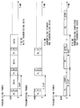
- FIG.1A is a timing chart showing data transmission timing during data transmission. Pilot symbols (hereafter referred to as "PL”) and transmission power control symbols (hereafter referred to as "TPC”) are periodically inserted into data, forming a frame. When a portion from the start of a PL to the start of the next PL is calculated as one slot, one frame generally consists of 16 slots, 10 ms.
- PL Pilot symbols
- TPC transmission power control symbols
- FIG.1B is a timing chart showing data transmission timing during transmission on transmission standby.
- "During transmission on transmission standby" means a time corresponding to less than K frames after completion of data transmission or a time corresponding to less than L frames in which a CRC detection of received data resulted in NG (K and L are predetermined constants).
- the CDMA mobile station apparatus transmits burst data in which only a PL and TPC are written and other bits are left in blank for each slot.
- the CRC (Cyclic Redundancy Check) detection means processing for detecting errors in received data by judgment by a comparison between a received CRC bit which is given with a coefficient of a remainder polynomial obtained by dividing an information bit by an n-th degree generating function, and a CRC bit generated from the received data.
- a complete match between the two means that the received data have been received correctly (OK) and mismatch of at least one element means that the received data contain errors (NG).
- FIG.1C is a timing chart showing the data transmission timing at the end of transmission.
- the end of transmission means a state in which at least K frames are detected after data transmission is completed and at least L frames in which a CRC detection of the received data resulted in NG are detected.
- the conventional CDMA mobile station apparatus stops transmission of burst data in a certain time after the end of communication in order to reduce power consumption of batteries by a transmission amplifier.
- the conventional CDMA mobile station apparatus above takes time to establish synchronization when restarting communication, and it has to send a dummy signal, an unnecessary signal, instead of data in the meantime until synchronization is established, resulting in a problem of reducing the transmission efficiency.
- a first objective of the present invention is to provide a CDMA mobile station apparatus and CDMA transmission method which can maintain established synchronization with a base station apparatus while reducing power consumption when there are no data to be transmitted.
- This objective is achieved by controlling the transmission interval of burst data to N slots (N: a natural number) when a certain time has elapsed after the end of data transmission.
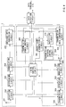
- FIG.2 is a block diagram showing the configuration of a CDMA mobile station apparatus in Embodiment 1 of the present invention.
- the CDMA mobile station apparatus shown in FIG.2 mainly comprises data detection circuit 1 that carries out data transmission/reception with a data terminal, data reception section 2 that processes a received radio signal, data transmission section 3 that processes data to be transmitted by radio, and timing control circuit 4 that controls whole timing and sequence of signal processing.
- Data reception section 2 comprises reception antenna 201 that receives a radio signal, reception circuit 202 that converts the frequency of the received signal to a baseband signal despreading circuit 203 that performs the correlation detection on the baseband signal and extracts data directed to the own station, demodulation circuit 204 that demodulates the data directed to the own station, and received data conversion circuit 205 that separates the demodulated data into a control signal and voice data or data terminal data and performs a CRC detection.
- Data transmission section 3 comprises transmission data conversion circuit 301 that inserts PLs and TPCs into data to be transmitted by radio forming a frame and carries out CRC coding, modulation circuit 302 that modulates the data combined into frames according to various modulation methods, spreading circuit 303 that spreads the modulated data, conversion/transmission circuit 304 that converts the spread signal to a signal with a desired carrier frequency, transmission antenna 305 that transmits the frequency-converted signal by radio, and transmission power control circuit 306 that determines transmission power and TPC according to the received signal and reception level, etc.
- data transmission section 3 comprises burst frame generation circuit 307 that generates burst frames consisting solely of PLs and TPCs, transmission interval control circuit 308 that controls transmission intervals of burst data, and switch 309 that switches connections based on the control signal of data detection circuit 1.
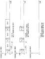
- FIG.3 is a timing chart showing the transmission timing of data in the CDMA mobile station apparatus in Embodiment 1.
- the time is plotted on the horizontal axis and transmission power is plotted on the vertical axis.
- FIG.3A is a timing chart showing the transmission timing of data during data transmission.
- PLs and TPCs are periodically inserted into the data output from data detection circuit 1 in transmission data conversion circuit 301, combined into a frame.
- Data combined into a frame are output to modulation circuit 302 via changeover switch 309.
- Data detection circuit 1 controls switch 309 during data transmission so that transmission data conversion circuit 301 and modulation circuit 302 are connected.
- the data input to modulation circuit 302 are modulated according to various modulation methods, spread by spreading circuit 303, converted to a signal with a desired carrier frequency by transmission circuit 304 with transmission power controlled and transmitted by radio from transmission antenna 305.
- data detection circuit 1 controls switch 309 so that transmission interval control circuit 308 and modulation circuit 302 are connected when there are no data to be transmitted.
- Burst frame generation circuit 307 generates burst data in which only PLs and TPCs are written and other bits are left in blank when there are no data to be transmitted.
- Transmission interval control circuit 308 controls the burst data transmission interval to one slot on transmission standby.
- "Transmission standby” means a time corresponding to less than K frames after completion of data transmission or a time corresponding to less than L frames in which a CRC detection of received data resulted in NG (K and L are predetermined constants).
- FIG.3B is a timing chart showing the transmission timing of data on transmission standby.
- Transmitting burst data when there are no data to be transmitted allows synchronization with the base station apparatus to be maintained, making it possible to restart communication immediately.
- transmission interval control circuit 308 controls the transmission interval of burst data to N times one slot (N: a natural number) at the end of transmission.
- the end of transmission means at least K frames after data transmission is completed and the time at which at least L frames are detected in each of which a CRC detection of received data resulted in NG.
- FIG.3C is a timing chart showing the transmission timing of data at the end of transmission.
- Burst data are output to modulation circuit 302 via changeover switch 309.
- the data input to modulation circuit 302 are modulated according to various modulation methods, spread by spreading circuit 303, converted to a signal with a desired carrier frequency by transmission circuit 304 with transmission power controlled and transmitted by radio from transmission antenna 305.
- controlling the transmission interval of burst data to N times one slot makes it possible to reduce power consumption of batteries by a transmission amplifier, shorten the time until synchronization is established when restarting transmission, reduce transmission of a dummy signal, an unnecessary signal, thus improving the transmission efficiency. Furthermore, transmitting burst data in a slot with a free space makes it possible to reduce interference with other stations.
- the transmission interval of burst data may be non-cyclic. Using a non-cyclic transmission interval of burst data makes it possible to avoid hearing aid problems, eliminating the danger of affecting through resonance heart pacemakers.
- Embodiment 2 is explained using FIG.4 and FIG.5.
- Embodiment 2 is an embodiment which performs repetition processing on burst data at the end of transmission.
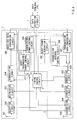
- FIG.4 is a block diagram showing the configuration of a CDMA mobile station apparatus in Embodiment 2.
- the same components as those in FIG.2 are assigned the same numbers and their explanations are omitted.
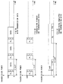
- FIG.5 is a timing chart showing the transmission timing of data of the CDMA mobile station apparatus in Embodiment 2.
- FIG.5A is a timing chart showing the transmission timing of data during data transmission
- FIG.5B is a timing chart showing the transmission timing of data on transmission standby. Since the transmission timing of data during data transmission and on transmission standby is the same as in FIG.3, its explanation is omitted.
- the CDMA mobile station apparatus shown in FIG.4 is provided with repetition processing circuit 310 added to data transmission section 3.
- Repetition processing circuit 310 performs repetition processing on PLs and TPCs of burst data input from burst frame generation circuit 307 at the end of transmission and outputs them to transmission interval control circuit 308.
- the repetition processing means processing of arranging the same information n times (n: a natural number) in series for PLs and TPCs.
- Transmission interval control circuit 308 sets the transmission interval of burst data subjected to repetition processing N times (N: a natural number) one slot.
- FIG.5C shows the transmission timing of data at the end of transmission.
- Burst data are output to modulation circuit 302 via changeover switch 309.
- the data input to modulation circuit 302 are modulated according to various modulation methods, spread by spreading circuit 303 and output to transmission circuit 304.
- Transmission circuit 304 controls the transmission power of burst data to 1/n of that prior to the repetition processing, converts the burst data to a signal with a desired carrier frequency and transmits it by radio from transmission antenna 305.
- n times (n: a natural number) and arranging them in series at the end of transmission can maintain synchronization even if the transmission power is reduced to 1/n of that prior to the repetition processing by transmission circuit 304, reducing interference with other stations.
- the transmission interval of burst data at the end of transmission may be non-cyclic.
- Embodiment 3 is explained using FIG.6 and FIG.7.
- Embodiment 3 is an embodiment which transmits burst data with a transmission power value extracted from the received data when the base station apparatus cannot transmit TPCs during non-cyclic transmission.
- FIG.6 is a block diagram showing the configuration of a CDMA mobile station apparatus in Embodiment 3 of the present invention.
- the same components as those in FIG.2 are assigned the same numbers as in FIG.2 and their explanations are omitted.
- FIG.7 is a timing chart showing the transmission timing of data of the CDMA mobile station apparatus in Embodiment 3.
- FIG.7A is a timing chart showing the transmission timing of data during data transmission.
- FIG.7B is a timing chart showing the transmission timing of data on transmission standby. Since the transmission timing of data during data transmission and on transmission standby is the same as in FIG.3, its explanation is omitted.
- the CDMA mobile station apparatus shown in FIG.6 is provided with burst transmission power control circuit 311 that controls the transmission power value of burst data using the transmission power value extracted from the received data instead of TPCs and switch 312 that switches connections based on the control signal of data detection circuit 1 added to data transmission section 3.
- Data detection circuit 1 controls switch 309 at the end of transmission so that transmission interval control circuit 308 and modulation circuit 302 are connected. It also controls switch 312 so that transmission circuit 304 and burst transmission power control circuit 311 are connected.
- Burst frame generation circuit 307 generates burst frames only from PLs and burst transmission power control symbols (hereafter referred to as "BTPC") at the end of transmission and outputs the burst data to transmission interval control circuit 308.
- BTPC burst transmission power control symbols
- Information indicating the transmission power value is written to the BTPC and the base station transmits the signal with the transmission power value written to the BTPC.
- Transmission interval control circuit 308 sets the burst data transmission interval to N times (N: a natural number) one slot at the end of transmission and sets it non-cyclic. Setting the burst data transmission interval non-cyclic can avoid hearing aid problems, eliminating the danger of affecting through resonance heart pacemakers.
- Burst data are output to modulation circuit 302 via changeover switch 309.
- the data input to modulation circuit 302 are modulated according to various modulation methods, spread by spreading circuit 303 and output to transmission circuit 304.
- Transmission circuit 304 inputs the transmission power value extracted from the received data from burst transmission power control circuit 311 at the end of transmission, controls the transmission power of the burst data to the same value as the transmission power value extracted from the received data, converts it to a signal with a desired carrier frequency and transmits it by radio from transmission antenna 305.
- FIG.7C is a timing chart showing the transmission timing of data at the end of transmission and transmission power value BdB at the end of transmission is the same as the transmission power value extracted from the received data.
- transmission circuit 304 sets the data transmission power to the same value as the transmission power value extracted from the received data, preventing it from interfering other stations by transmitting too high a power value and preventing it from failing to maintain synchronization by transmitting too low a power value.
- FIG.8 is a block diagram showing a 2nd configuration of the CDMA mobile station apparatus in Embodiment 3 and repetition processing circuit 310 is added to FIG.6.
- FIG.9 is a 2nd timing chart showing the data transmission timing of the CDMA mobile station apparatus in Embodiment 3 which performs repetition processing on FIG.7 at the end of transmission.
- Carrying out repetition processing allows synchronization to be maintained even if the transmission power value is reduced by transmission circuit 304, making it possible to reduce interference with other stations.
- the burst data transmission interval can be controlled when there are no data to be transmitted, making it possible to maintain synchronization while reducing power consumption.
Abstract
Description
- The present invention relates to CDMA mobile station apparatuses and CDMA transmission methods such as digital car telephones and portable telephones used for cellular radio communication systems.
- For radio communication systems such as digital car telephones and portable telephones, a multiple access system is used in which multiple mobile station apparatuses perform communications with a single base station apparatus simultaneously. Recently, as one of these line switching systems using this multiple access system, a CDMA (Code Division Multiple Access) system is used because of its high frequency utilization efficiency.
- Data transmission timing in a conventional CDMA mobile station apparatus is explained using a timing chart shown in FIG. 1.
- FIG.1A is a timing chart showing data transmission timing during data transmission. Pilot symbols (hereafter referred to as "PL") and transmission power control symbols (hereafter referred to as "TPC") are periodically inserted into data, forming a frame. When a portion from the start of a PL to the start of the next PL is calculated as one slot, one frame generally consists of 16 slots, 10 ms.
- FIG.1B is a timing chart showing data transmission timing during transmission on transmission standby. "During transmission on transmission standby" means a time corresponding to less than K frames after completion of data transmission or a time corresponding to less than L frames in which a CRC detection of received data resulted in NG (K and L are predetermined constants). On transmission standby, the CDMA mobile station apparatus transmits burst data in which only a PL and TPC are written and other bits are left in blank for each slot.
- Here, the CRC (Cyclic Redundancy Check) detection means processing for detecting errors in received data by judgment by a comparison between a received CRC bit which is given with a coefficient of a remainder polynomial obtained by dividing an information bit by an n-th degree generating function, and a CRC bit generated from the received data. A complete match between the two means that the received data have been received correctly (OK) and mismatch of at least one element means that the received data contain errors (NG).
- FIG.1C is a timing chart showing the data transmission timing at the end of transmission. The end of transmission means a state in which at least K frames are detected after data transmission is completed and at least L frames in which a CRC detection of the received data resulted in NG are detected.
- As shown in FIG.1C, the conventional CDMA mobile station apparatus stops transmission of burst data in a certain time after the end of communication in order to reduce power consumption of batteries by a transmission amplifier.
- Because of this, the conventional CDMA mobile station apparatus above takes time to establish synchronization when restarting communication, and it has to send a dummy signal, an unnecessary signal, instead of data in the meantime until synchronization is established, resulting in a problem of reducing the transmission efficiency.
- A first objective of the present invention is to provide a CDMA mobile station apparatus and CDMA transmission method which can maintain established synchronization with a base station apparatus while reducing power consumption when there are no data to be transmitted.
- This objective is achieved by controlling the transmission interval of burst data to N slots (N: a natural number) when a certain time has elapsed after the end of data transmission.
-
- FIG.1 is a timing chart showing the transmission timing of data in a conventional CDMA mobile station apparatus;
- FIG.2 is a block diagram showing the configuration
of a CDMA mobile station apparatus in
Embodiment 1 of the present invention; - FIG.3 is a timing chart showing the transmission
timing of data in the CDMA mobile station apparatus in
Embodiment 1 of the present invention; - FIG.4 is a block diagram showing the configuration
of a CDMA mobile station apparatus in
Embodiment 2 of the present invention; - FIG.5 is a timing chart showing the transmission
timing of data in the CDMA mobile station apparatus in
Embodiment 2 of the present invention; - FIG.6 is a 1st block diagram showing the
configuration of a CDMA mobile station apparatus in
Embodiment 3 of the present invention; - FIG.7 is a 1st timing chart showing the transmission
timing of data in the CDMA mobile station apparatus in
Embodiment 3 of the present invention; - FIG.8 is a 2nd block diagram showing the
configuration of the CDMA mobile station apparatus in
Embodiment 3 of the present invention; - FIG.9 is a 2nd timing chart showing the transmission
timing of data in the CDMA mobile station apparatus in
Embodiment 3 of the present invention. -
- With reference now to the attached drawings, the best modes for carrying out the present invention are explained in detail.
- FIG.2 is a block diagram showing the configuration of a CDMA mobile station apparatus in
Embodiment 1 of the present invention. - The CDMA mobile station apparatus shown in FIG.2 mainly comprises
data detection circuit 1 that carries out data transmission/reception with a data terminal,data reception section 2 that processes a received radio signal,data transmission section 3 that processes data to be transmitted by radio, andtiming control circuit 4 that controls whole timing and sequence of signal processing. -
Data reception section 2 comprisesreception antenna 201 that receives a radio signal,reception circuit 202 that converts the frequency of the received signal to a baseband signal despreadingcircuit 203 that performs the correlation detection on the baseband signal and extracts data directed to the own station,demodulation circuit 204 that demodulates the data directed to the own station, and receiveddata conversion circuit 205 that separates the demodulated data into a control signal and voice data or data terminal data and performs a CRC detection. -
Data transmission section 3 comprises transmissiondata conversion circuit 301 that inserts PLs and TPCs into data to be transmitted by radio forming a frame and carries out CRC coding,modulation circuit 302 that modulates the data combined into frames according to various modulation methods, spreadingcircuit 303 that spreads the modulated data, conversion/transmission circuit 304 that converts the spread signal to a signal with a desired carrier frequency,transmission antenna 305 that transmits the frequency-converted signal by radio, and transmissionpower control circuit 306 that determines transmission power and TPC according to the received signal and reception level, etc. - Furthermore,
data transmission section 3 comprises burstframe generation circuit 307 that generates burst frames consisting solely of PLs and TPCs, transmissioninterval control circuit 308 that controls transmission intervals of burst data, andswitch 309 that switches connections based on the control signal ofdata detection circuit 1. - FIG.3 is a timing chart showing the transmission timing of data in the CDMA mobile station apparatus in Embodiment 1. In the following timing charts, the time is plotted on the horizontal axis and transmission power is plotted on the vertical axis.
- FIG.3A is a timing chart showing the transmission timing of data during data transmission. As shown in FIG.3A, PLs and TPCs are periodically inserted into the data output from
data detection circuit 1 in transmissiondata conversion circuit 301, combined into a frame. Data combined into a frame are output tomodulation circuit 302 viachangeover switch 309. -
Data detection circuit 1 controls switch 309 during data transmission so that transmissiondata conversion circuit 301 andmodulation circuit 302 are connected. The data input tomodulation circuit 302 are modulated according to various modulation methods, spread by spreadingcircuit 303, converted to a signal with a desired carrier frequency bytransmission circuit 304 with transmission power controlled and transmitted by radio fromtransmission antenna 305. - On the other hand,
data detection circuit 1 controls switch 309 so that transmissioninterval control circuit 308 andmodulation circuit 302 are connected when there are no data to be transmitted. - Burst
frame generation circuit 307 generates burst data in which only PLs and TPCs are written and other bits are left in blank when there are no data to be transmitted. - Transmission
interval control circuit 308 controls the burst data transmission interval to one slot on transmission standby. "Transmission standby" means a time corresponding to less than K frames after completion of data transmission or a time corresponding to less than L frames in which a CRC detection of received data resulted in NG (K and L are predetermined constants). FIG.3B is a timing chart showing the transmission timing of data on transmission standby. - Transmitting burst data when there are no data to be transmitted allows synchronization with the base station apparatus to be maintained, making it possible to restart communication immediately.
- However, continuing transmission of burst data for a long time after the end of data transmission results in an increase of power consumption of batteries by a transmission amplifier.
- On the other hand, if transmission of burst data is completely stopped, it takes time to establish synchronization with the base station apparatus when restarting transmission.
- Therefore, transmission
interval control circuit 308 controls the transmission interval of burst data to N times one slot (N: a natural number) at the end of transmission. The end of transmission means at least K frames after data transmission is completed and the time at which at least L frames are detected in each of which a CRC detection of received data resulted in NG. FIG.3C is a timing chart showing the transmission timing of data at the end of transmission. - Burst data are output to
modulation circuit 302 viachangeover switch 309. The data input tomodulation circuit 302 are modulated according to various modulation methods, spread by spreadingcircuit 303, converted to a signal with a desired carrier frequency bytransmission circuit 304 with transmission power controlled and transmitted by radio fromtransmission antenna 305. - As described above, controlling the transmission interval of burst data to N times one slot makes it possible to reduce power consumption of batteries by a transmission amplifier, shorten the time until synchronization is established when restarting transmission, reduce transmission of a dummy signal, an unnecessary signal, thus improving the transmission efficiency. Furthermore, transmitting burst data in a slot with a free space makes it possible to reduce interference with other stations.
- Here, the transmission interval of burst data may be non-cyclic. Using a non-cyclic transmission interval of burst data makes it possible to avoid hearing aid problems, eliminating the danger of affecting through resonance heart pacemakers.
- Then, Embodiment 2 is explained using FIG.4 and FIG.5.
-
Embodiment 2 is an embodiment which performs repetition processing on burst data at the end of transmission. - FIG.4 is a block diagram showing the configuration of a CDMA mobile station apparatus in
Embodiment 2. In the CDMA mobile station apparatus shown in FIG.4, the same components as those in FIG.2 are assigned the same numbers and their explanations are omitted. - FIG.5 is a timing chart showing the transmission timing of data of the CDMA mobile station apparatus in
Embodiment 2. FIG.5A is a timing chart showing the transmission timing of data during data transmission and FIG.5B is a timing chart showing the transmission timing of data on transmission standby. Since the transmission timing of data during data transmission and on transmission standby is the same as in FIG.3, its explanation is omitted. - In comparison with FIG.2, the CDMA mobile station apparatus shown in FIG.4 is provided with
repetition processing circuit 310 added todata transmission section 3. -
Repetition processing circuit 310 performs repetition processing on PLs and TPCs of burst data input from burstframe generation circuit 307 at the end of transmission and outputs them to transmissioninterval control circuit 308. The repetition processing means processing of arranging the same information n times (n: a natural number) in series for PLs and TPCs. - Transmission
interval control circuit 308 sets the transmission interval of burst data subjected to repetition processing N times (N: a natural number) one slot. FIG.5C shows the transmission timing of data at the end of transmission. - Burst data are output to
modulation circuit 302 viachangeover switch 309. The data input tomodulation circuit 302 are modulated according to various modulation methods, spread by spreadingcircuit 303 and output totransmission circuit 304. -
Transmission circuit 304 controls the transmission power of burst data to 1/n of that prior to the repetition processing, converts the burst data to a signal with a desired carrier frequency and transmits it by radio fromtransmission antenna 305. - Repeating the same information n times (n: a natural number) and arranging them in series at the end of transmission can maintain synchronization even if the transmission power is reduced to 1/n of that prior to the repetition processing by
transmission circuit 304, reducing interference with other stations. The transmission interval of burst data at the end of transmission may be non-cyclic. - Then,
Embodiment 3 is explained using FIG.6 and FIG.7. -
Embodiment 3 is an embodiment which transmits burst data with a transmission power value extracted from the received data when the base station apparatus cannot transmit TPCs during non-cyclic transmission. - FIG.6 is a block diagram showing the configuration of a CDMA mobile station apparatus in
Embodiment 3 of the present invention. In the CDMA mobile station apparatus shown in FIG. 6, the same components as those in FIG.2 are assigned the same numbers as in FIG.2 and their explanations are omitted. - FIG.7 is a timing chart showing the transmission timing of data of the CDMA mobile station apparatus in
Embodiment 3. FIG.7A is a timing chart showing the transmission timing of data during data transmission. FIG.7B is a timing chart showing the transmission timing of data on transmission standby. Since the transmission timing of data during data transmission and on transmission standby is the same as in FIG.3, its explanation is omitted. - In comparison with FIG.2, the CDMA mobile station apparatus shown in FIG.6 is provided with burst transmission
power control circuit 311 that controls the transmission power value of burst data using the transmission power value extracted from the received data instead of TPCs and switch 312 that switches connections based on the control signal ofdata detection circuit 1 added todata transmission section 3. -
Data detection circuit 1 controls switch 309 at the end of transmission so that transmissioninterval control circuit 308 andmodulation circuit 302 are connected. It also controlsswitch 312 so thattransmission circuit 304 and burst transmissionpower control circuit 311 are connected. - Burst
frame generation circuit 307 generates burst frames only from PLs and burst transmission power control symbols (hereafter referred to as "BTPC") at the end of transmission and outputs the burst data to transmissioninterval control circuit 308. Information indicating the transmission power value is written to the BTPC and the base station transmits the signal with the transmission power value written to the BTPC. - Transmission
interval control circuit 308 sets the burst data transmission interval to N times (N: a natural number) one slot at the end of transmission and sets it non-cyclic. Setting the burst data transmission interval non-cyclic can avoid hearing aid problems, eliminating the danger of affecting through resonance heart pacemakers. - Burst data are output to
modulation circuit 302 viachangeover switch 309. The data input tomodulation circuit 302 are modulated according to various modulation methods, spread by spreadingcircuit 303 and output totransmission circuit 304. -
Transmission circuit 304 inputs the transmission power value extracted from the received data from burst transmissionpower control circuit 311 at the end of transmission, controls the transmission power of the burst data to the same value as the transmission power value extracted from the received data, converts it to a signal with a desired carrier frequency and transmits it by radio fromtransmission antenna 305. - FIG.7C is a timing chart showing the transmission timing of data at the end of transmission and transmission power value BdB at the end of transmission is the same as the transmission power value extracted from the received data.
- Thus, during non-cyclic transmission when the base station apparatus cannot transmit TPCs,
transmission circuit 304 sets the data transmission power to the same value as the transmission power value extracted from the received data, preventing it from interfering other stations by transmitting too high a power value and preventing it from failing to maintain synchronization by transmitting too low a power value. - It is also possible to perform repetition processing on burst data by adding
repetition processing circuit 310 toEmbodiment 3. FIG.8 is a block diagram showing a 2nd configuration of the CDMA mobile station apparatus inEmbodiment 3 andrepetition processing circuit 310 is added to FIG.6. FIG.9 is a 2nd timing chart showing the data transmission timing of the CDMA mobile station apparatus inEmbodiment 3 which performs repetition processing on FIG.7 at the end of transmission. - Carrying out repetition processing allows synchronization to be maintained even if the transmission power value is reduced by
transmission circuit 304, making it possible to reduce interference with other stations. - As explained above, according to the CDMA transmission apparatus and CDMA transmission method of the present invention, the burst data transmission interval can be controlled when there are no data to be transmitted, making it possible to maintain synchronization while reducing power consumption.
Claims (10)
- A CDMA mobile station apparatus, comprising :transmission frame generation means for generating frames by inserting pilot symbols and transmission power control symbols into transmission data;burst frame generation means for generating burst frames solely made up of pilot symbols and transmission power control symbols;transmission interval control means for controlling a transmission interval of said burst data; andtransmission means for transmitting said transmission data and said burst data by radio.
- The CDMA mobile station apparatus according to claim 1, comprising :repetition processing means for arranging pilot symbols and transmission power control symbols in series respectively.
- The CDMA mobile station apparatus according to claim 1, wherein transmission interval control means transmits burst data non-cyclically.
- The CDMA mobile station apparatus according to claim 3, wherein burst frame generation means generates burst frames using burst transmission power symbols instead of transmission power control symbols and transmission means transmits said burst data with a same value as a transmission power value extracted from received data.
- A CDMA base station apparatus, which performs cellular radio communications with the CDMA mobile station apparatus according to claim 1.
- A cellular radio communication system, which performs cellular radio communications using the CDMA mobile station apparatus according to claim 1 and the CDMA base station apparatus according to claim 5.
- A CDMA transmission method, which generates transmission frames by inserting pilot symbols and transmission power control symbols into transmission data, transmits transmission data by radio, generates burst frames solely made up of pilot symbols and transmission power control symbols if there are no transmission data and transmits burst data by radio by controlling transmission intervals.
- The CDMA transmission method according to claim 7, which transmits by radio burst data subjected to processing of arranging pilot symbols and transmission power control symbols in series respectively.
- The CDMA transmission method according to claim 7, which transmits burst data non-cyclically.
- The CDMA transmission method according to claim 9, which generates burst frames using burst transmission power symbols instead of transmission power control symbols and sets a burst data transmission power value same as a transmission power value extracted from received data.
Applications Claiming Priority (3)
| Application Number | Priority Date | Filing Date | Title |
|---|---|---|---|
| JP20964297 | 1997-07-19 | ||
| JP20964297A JP3655057B2 (en) | 1997-07-19 | 1997-07-19 | CDMA transmitter and CDMA transmission method |
| PCT/JP1998/003202 WO1999004591A1 (en) | 1997-07-19 | 1998-07-16 | Cdma mobile station and cdma transmission method |
Publications (3)
| Publication Number | Publication Date |
|---|---|
| EP0936831A1 true EP0936831A1 (en) | 1999-08-18 |
| EP0936831A4 EP0936831A4 (en) | 2003-04-02 |
| EP0936831B1 EP0936831B1 (en) | 2005-09-28 |
Family
ID=16576180
Family Applications (1)
| Application Number | Title | Priority Date | Filing Date |
|---|---|---|---|
| EP98932553A Expired - Lifetime EP0936831B1 (en) | 1997-07-19 | 1998-07-16 | Cdma mobile station and cdma transmission method |
Country Status (10)
| Country | Link |
|---|---|
| US (2) | US6466563B1 (en) |
| EP (1) | EP0936831B1 (en) |
| JP (1) | JP3655057B2 (en) |
| KR (1) | KR100295734B1 (en) |
| CN (2) | CN100442686C (en) |
| AU (1) | AU8243498A (en) |
| CA (2) | CA2429736A1 (en) |
| DE (1) | DE69831726T2 (en) |
| ES (1) | ES2251091T3 (en) |
| WO (1) | WO1999004591A1 (en) |
Cited By (5)
| Publication number | Priority date | Publication date | Assignee | Title |
|---|---|---|---|---|
| WO2001063794A2 (en) * | 2000-02-25 | 2001-08-30 | Nokia Corporation | User equipment and procedure for handling possible out-of-synchronization condition |
| EP1257075A1 (en) * | 2001-01-12 | 2002-11-13 | Matsushita Electric Industrial Co., Ltd. | Transmitting device and transmitting method |
| US7929723B2 (en) | 1997-01-13 | 2011-04-19 | Micro Ear Technology, Inc. | Portable system for programming hearing aids |
| US8300862B2 (en) | 2006-09-18 | 2012-10-30 | Starkey Kaboratories, Inc | Wireless interface for programming hearing assistance devices |
| US9344817B2 (en) | 2000-01-20 | 2016-05-17 | Starkey Laboratories, Inc. | Hearing aid systems |
Families Citing this family (21)
| Publication number | Priority date | Publication date | Assignee | Title |
|---|---|---|---|---|
| US6301237B1 (en) | 1997-12-30 | 2001-10-09 | Matsushita Electric Industrial Co., Ltd. | CDMA radio multiplex transmitting device and a CDMA radio multiplex receiving device |
| JP2000209128A (en) * | 1999-01-18 | 2000-07-28 | Matsushita Electric Ind Co Ltd | Receiver |
| US6608868B1 (en) | 1999-01-19 | 2003-08-19 | Matsushita Electric Industrial Co., Ltd. | Apparatus and method for digital wireless communications |
| KR100651457B1 (en) * | 1999-02-13 | 2006-11-28 | 삼성전자주식회사 | Method of contiguous outer loop power control in dtx mode of cdma mobile communication system |
| EP1420538B1 (en) * | 1999-04-12 | 2012-06-13 | QUALCOMM Incorporated | Method for gated transmission in a CDMA communication system |
| KR100605978B1 (en) | 1999-05-29 | 2006-07-28 | 삼성전자주식회사 | Transceiver apparatus and method for continuous outer loop power control in dtx mode of cdma mobile communication system |
| KR100492968B1 (en) * | 1999-05-29 | 2005-06-07 | 삼성전자주식회사 | Apparatus and method for transmitting a channel signal gated in the control only substate of cdma communications system |
| US6496706B1 (en) * | 1999-07-23 | 2002-12-17 | Qualcomm Incorporated | Method and system for transmit gating in a wireless communication system |
| EP2259529B1 (en) | 1999-07-28 | 2019-03-27 | Panasonic Intellectual Property Corporation of America | Apparatus for the transmission and reception of data and method for digital radio communication |
| US6626918B1 (en) * | 2000-10-06 | 2003-09-30 | Medical Technology Group | Apparatus and methods for positioning a vascular sheath |
| US20030027587A1 (en) | 2001-06-13 | 2003-02-06 | Tantivy Communications, Inc. | System and method for coordination of wireless maintenance channel power control |
| CA2474340C (en) * | 2002-01-08 | 2015-12-01 | Ipr Licensing, Inc. | Maintaining a maintenance channel in a reverse link of a wireless communications system |
| TW200733596A (en) | 2002-10-17 | 2007-09-01 | Interdigital Tech Corp | Power control for communications systems utilizing high speed shared channels |
| CN1993906B (en) | 2004-07-22 | 2010-04-28 | 三菱电机株式会社 | Base station and mobile equipment |
| US8014807B2 (en) * | 2004-12-28 | 2011-09-06 | Panasonic Corporation | Transmission power control apparatus, propagation path estimating apparatus, transmission power control method, and propagation path estimating method |
| KR100908261B1 (en) * | 2006-04-28 | 2009-07-20 | 엘지전자 주식회사 | Apparatus and method for controlling power timing in a mobile communication terminal |
| CN101282145B (en) * | 2007-04-06 | 2013-02-13 | 鼎桥通信技术有限公司 | Method and apparatus for controlling transmission power and synchronization in TD-SCDMA system |
| KR101459147B1 (en) * | 2008-02-04 | 2014-11-10 | 엘지전자 주식회사 | Method of transmitting transmit power control command in wireless communication system |
| JP6014421B2 (en) * | 2012-08-30 | 2016-10-25 | 株式会社Nttドコモ | Base station and transmission power control method |
| US20160329989A1 (en) * | 2015-05-05 | 2016-11-10 | Intel IP Corporation | High-efficiency wireless preamble structures with efficient cyclic redundancy check |
| JP2018056795A (en) * | 2016-09-29 | 2018-04-05 | 住友電工システムソリューション株式会社 | Roadside communication device, packet transmission method, and computer program |
Citations (3)
| Publication number | Priority date | Publication date | Assignee | Title |
|---|---|---|---|---|
| EP0682418A2 (en) * | 1994-05-12 | 1995-11-15 | Ntt Mobile Communications Network Inc. | Transmission power control for mobile radio |
| EP0758168A1 (en) * | 1995-02-23 | 1997-02-12 | Ntt Mobile Communications Network Inc. | Variable rate transmitting method, and transmitter and receiver using it |
| EP1011211A1 (en) * | 1997-04-17 | 2000-06-21 | Ntt Mobile Communications Network Inc. | Base station apparatus of mobile communication system |
Family Cites Families (6)
| Publication number | Priority date | Publication date | Assignee | Title |
|---|---|---|---|---|
| FI94579C (en) * | 1994-01-12 | 1995-09-25 | Nokia Mobile Phones Ltd | Data Transfer method |
| JP2658879B2 (en) * | 1994-06-15 | 1997-09-30 | 日本電気株式会社 | MONITORING METHOD, MONITORING METHOD, AND TERMINAL OF MULTI-DIRECTIONAL MULTIPLE COMMUNICATION SYSTEM |
| EP0833472B1 (en) * | 1996-04-12 | 2006-09-20 | NTT DoCoMo, Inc. | Method and instrument for measuring receiving sir and transmission power controller |
| JP2785804B2 (en) * | 1996-05-30 | 1998-08-13 | 日本電気株式会社 | Mobile communication system |
| CA2210179C (en) * | 1996-07-12 | 2001-09-11 | Ntt Mobile Communications Network Inc. | Radio channel initial transmission scheme for mobile communication system |
| JP2923867B2 (en) * | 1996-10-28 | 1999-07-26 | 日本電気株式会社 | Transmission power control method |
-
1997
- 1997-07-19 JP JP20964297A patent/JP3655057B2/en not_active Expired - Lifetime
-
1998
- 1998-07-16 DE DE69831726T patent/DE69831726T2/en not_active Expired - Lifetime
- 1998-07-16 WO PCT/JP1998/003202 patent/WO1999004591A1/en active IP Right Grant
- 1998-07-16 CN CNB031083528A patent/CN100442686C/en not_active Expired - Lifetime
- 1998-07-16 US US09/147,831 patent/US6466563B1/en not_active Expired - Lifetime
- 1998-07-16 CA CA 2429736 patent/CA2429736A1/en not_active Abandoned
- 1998-07-16 AU AU82434/98A patent/AU8243498A/en not_active Abandoned
- 1998-07-16 CN CN98801017A patent/CN1109476C/en not_active Expired - Lifetime
- 1998-07-16 ES ES98932553T patent/ES2251091T3/en not_active Expired - Lifetime
- 1998-07-16 EP EP98932553A patent/EP0936831B1/en not_active Expired - Lifetime
- 1998-07-16 CA CA002266104A patent/CA2266104C/en not_active Expired - Lifetime
-
1999
- 1999-03-18 KR KR1019997002300A patent/KR100295734B1/en not_active IP Right Cessation
-
2002
- 2002-09-06 US US10/235,918 patent/US20030007472A1/en not_active Abandoned
Patent Citations (3)
| Publication number | Priority date | Publication date | Assignee | Title |
|---|---|---|---|---|
| EP0682418A2 (en) * | 1994-05-12 | 1995-11-15 | Ntt Mobile Communications Network Inc. | Transmission power control for mobile radio |
| EP0758168A1 (en) * | 1995-02-23 | 1997-02-12 | Ntt Mobile Communications Network Inc. | Variable rate transmitting method, and transmitter and receiver using it |
| EP1011211A1 (en) * | 1997-04-17 | 2000-06-21 | Ntt Mobile Communications Network Inc. | Base station apparatus of mobile communication system |
Non-Patent Citations (1)
| Title |
|---|
| See also references of WO9904591A1 * |
Cited By (10)
| Publication number | Priority date | Publication date | Assignee | Title |
|---|---|---|---|---|
| US7929723B2 (en) | 1997-01-13 | 2011-04-19 | Micro Ear Technology, Inc. | Portable system for programming hearing aids |
| US9344817B2 (en) | 2000-01-20 | 2016-05-17 | Starkey Laboratories, Inc. | Hearing aid systems |
| US9357317B2 (en) | 2000-01-20 | 2016-05-31 | Starkey Laboratories, Inc. | Hearing aid systems |
| WO2001063794A2 (en) * | 2000-02-25 | 2001-08-30 | Nokia Corporation | User equipment and procedure for handling possible out-of-synchronization condition |
| WO2001063794A3 (en) * | 2000-02-25 | 2002-03-14 | Nokia Corp | User equipment and procedure for handling possible out-of-synchronization condition |
| US6456826B1 (en) | 2000-02-25 | 2002-09-24 | Nokia Mobile Phones Ltd. | User equipment and procedure for handling possible out-of-synchronization condition in UMTS terrestrial radio access network for time division duplexing mode |
| EP1257075A1 (en) * | 2001-01-12 | 2002-11-13 | Matsushita Electric Industrial Co., Ltd. | Transmitting device and transmitting method |
| EP1257075A4 (en) * | 2001-01-12 | 2009-09-23 | Panasonic Corp | Transmitting device and transmitting method |
| EP2276184A1 (en) * | 2001-01-12 | 2011-01-19 | Panasonic Corporation | Transmission apparatus and transmission method |
| US8300862B2 (en) | 2006-09-18 | 2012-10-30 | Starkey Kaboratories, Inc | Wireless interface for programming hearing assistance devices |
Also Published As
| Publication number | Publication date |
|---|---|
| US20030007472A1 (en) | 2003-01-09 |
| CN1481098A (en) | 2004-03-10 |
| US6466563B1 (en) | 2002-10-15 |
| KR100295734B1 (en) | 2001-08-07 |
| JPH1141203A (en) | 1999-02-12 |
| CN1109476C (en) | 2003-05-21 |
| CN100442686C (en) | 2008-12-10 |
| CA2429736A1 (en) | 1999-01-28 |
| EP0936831A4 (en) | 2003-04-02 |
| EP0936831B1 (en) | 2005-09-28 |
| KR20000068588A (en) | 2000-11-25 |
| ES2251091T3 (en) | 2006-04-16 |
| WO1999004591A1 (en) | 1999-01-28 |
| CA2266104A1 (en) | 1999-01-28 |
| AU8243498A (en) | 1999-02-10 |
| CN1234954A (en) | 1999-11-10 |
| JP3655057B2 (en) | 2005-06-02 |
| DE69831726D1 (en) | 2006-02-09 |
| CA2266104C (en) | 2003-09-30 |
| DE69831726T2 (en) | 2006-03-23 |
Similar Documents
| Publication | Publication Date | Title |
|---|---|---|
| CA2266104C (en) | Cdma mobile station and cdma transmission method | |
| US7006463B2 (en) | CDMA communication system and its transmission power control method | |
| KR100585980B1 (en) | User equipment (ue) having acqisition circuit for 1.28 mcps chip rate mobile telecommunication system | |
| EP0960541B1 (en) | Circuit for synchronizing cdma mobile phones | |
| US5586122A (en) | Time division multiple access mobile wireless telecommunication system | |
| JP3392630B2 (en) | Spread spectrum communication equipment | |
| WO2002001747A2 (en) | Re-synchronization method for a communication device | |
| US7272125B2 (en) | Channel switching method and mobile communication terminal using the same | |
| US7190691B2 (en) | Method of controlling timing for uplink synchronous transmission scheme | |
| JP3819844B2 (en) | Radio base system, synchronous burst transmission control method, and transmission control program | |
| JP2007110759A (en) | Cdma mobile transmission apparatus and method using same | |
| JP3972042B2 (en) | CDMA mobile transmitter and method using the same | |
| EP0910191A1 (en) | Radio communication equipment | |
| EP0818893B1 (en) | Radio channel initial transmission scheme for mobile communication system | |
| KR100762594B1 (en) | Method for controlling synchronization of uplink signal | |
| EP1443679A3 (en) | Method and base station for transmitting information on a common packet data channel | |
| JPH11266199A (en) | Radio communication base station device | |
| JP3675247B2 (en) | Code division multiple access communication system and transmission power control method | |
| CN201039178Y (en) | Synchronization control subsystem for TD-SCDMA mobile terminal | |
| JP2005168059A (en) | Code division multiple access communication systems and transmission power control method | |
| JP2007318784A (en) | Code division multiple access communication systems and transmission power control method | |
| JP2007306607A (en) | Code division multiple access communication system and transmission power control method |
Legal Events
| Date | Code | Title | Description |
|---|---|---|---|
| PUAI | Public reference made under article 153(3) epc to a published international application that has entered the european phase |
Free format text: ORIGINAL CODE: 0009012 |
|
| 17P | Request for examination filed |
Effective date: 19990311 |
|
| AK | Designated contracting states |
Kind code of ref document: A1 Designated state(s): DE ES FR GB IT NL |
|
| RAP1 | Party data changed (applicant data changed or rights of an application transferred) |
Owner name: MATSUSHITA ELECTRIC INDUSTRIAL CO., LTD. |
|
| A4 | Supplementary search report drawn up and despatched |
Effective date: 20030214 |
|
| RIC1 | Information provided on ipc code assigned before grant |
Ipc: 7H 04B 7/005 B Ipc: 7H 04Q 7/38 A |
|
| 17Q | First examination report despatched |
Effective date: 20030422 |
|
| GRAP | Despatch of communication of intention to grant a patent |
Free format text: ORIGINAL CODE: EPIDOSNIGR1 |
|
| GRAS | Grant fee paid |
Free format text: ORIGINAL CODE: EPIDOSNIGR3 |
|
| GRAA | (expected) grant |
Free format text: ORIGINAL CODE: 0009210 |
|
| AK | Designated contracting states |
Kind code of ref document: B1 Designated state(s): DE ES FR GB IT NL |
|
| REG | Reference to a national code |
Ref country code: GB Ref legal event code: FG4D |
|
| REF | Corresponds to: |
Ref document number: 69831726 Country of ref document: DE Date of ref document: 20060209 Kind code of ref document: P |
|
| REG | Reference to a national code |
Ref country code: ES Ref legal event code: FG2A Ref document number: 2251091 Country of ref document: ES Kind code of ref document: T3 |
|
| ET | Fr: translation filed | ||
| PLBE | No opposition filed within time limit |
Free format text: ORIGINAL CODE: 0009261 |
|
| STAA | Information on the status of an ep patent application or granted ep patent |
Free format text: STATUS: NO OPPOSITION FILED WITHIN TIME LIMIT |
|
| 26N | No opposition filed |
Effective date: 20060629 |
|
| REG | Reference to a national code |
Ref country code: NL Ref legal event code: TD Effective date: 20131127 |
|
| REG | Reference to a national code |
Ref country code: ES Ref legal event code: PC2A Owner name: PANASONIC CORPORATION Effective date: 20131223 |
|
| REG | Reference to a national code |
Ref country code: FR Ref legal event code: CD Owner name: PANASONIC CORPORATION, JP Effective date: 20131217 |
|
| REG | Reference to a national code |
Ref country code: GB Ref legal event code: 732E Free format text: REGISTERED BETWEEN 20140925 AND 20141001 |
|
| REG | Reference to a national code |
Ref country code: DE Ref legal event code: R082 Ref document number: 69831726 Country of ref document: DE Representative=s name: EISENFUEHR SPEISER PATENTANWAELTE RECHTSANWAEL, DE |
|
| REG | Reference to a national code |
Ref country code: DE Ref legal event code: R079 Ref document number: 69831726 Country of ref document: DE Free format text: PREVIOUS MAIN CLASS: H04Q0007380000 Ipc: H04W0004000000 |
|
| REG | Reference to a national code |
Ref country code: DE Ref legal event code: R082 Ref document number: 69831726 Country of ref document: DE Representative=s name: EISENFUEHR SPEISER PATENTANWAELTE RECHTSANWAEL, DE Effective date: 20150109 Ref country code: DE Ref legal event code: R081 Ref document number: 69831726 Country of ref document: DE Owner name: INVT SPE LLC (N.D.GES.D. STAATES DELAWARE), SA, US Free format text: FORMER OWNER: PANASONIC CORPORATION, KADOMA-SHI, OSAKA, JP Effective date: 20150109 Ref country code: DE Ref legal event code: R081 Ref document number: 69831726 Country of ref document: DE Owner name: INVENTERGY, INC. (N.D.GES.D. STAATES DELAWARE), US Free format text: FORMER OWNER: PANASONIC CORPORATION, KADOMA-SHI, OSAKA, JP Effective date: 20150109 Ref country code: DE Ref legal event code: R079 Ref document number: 69831726 Country of ref document: DE Free format text: PREVIOUS MAIN CLASS: H04Q0007380000 Ipc: H04W0004000000 Effective date: 20150112 |
|
| REG | Reference to a national code |
Ref country code: GB Ref legal event code: 732E Free format text: REGISTERED BETWEEN 20150129 AND 20150204 |
|
| REG | Reference to a national code |
Ref country code: FR Ref legal event code: PLFP Year of fee payment: 18 |
|
| REG | Reference to a national code |
Ref country code: FR Ref legal event code: TP Owner name: INVENTERGY, INC., US Effective date: 20151027 |
|
| REG | Reference to a national code |
Ref country code: FR Ref legal event code: PLFP Year of fee payment: 19 |
|
| REG | Reference to a national code |
Ref country code: FR Ref legal event code: PLFP Year of fee payment: 20 |
|
| PGFP | Annual fee paid to national office [announced via postgrant information from national office to epo] |
Ref country code: FR Payment date: 20170628 Year of fee payment: 20 |
|
| PGFP | Annual fee paid to national office [announced via postgrant information from national office to epo] |
Ref country code: NL Payment date: 20170628 Year of fee payment: 20 |
|
| REG | Reference to a national code |
Ref country code: DE Ref legal event code: R082 Ref document number: 69831726 Country of ref document: DE Representative=s name: EISENFUEHR SPEISER PATENTANWAELTE RECHTSANWAEL, DE Ref country code: DE Ref legal event code: R081 Ref document number: 69831726 Country of ref document: DE Owner name: INVT SPE LLC (N.D.GES.D. STAATES DELAWARE), SA, US Free format text: FORMER OWNER: INVENTERGY, INC. (N.D.GES.D. STAATES DELAWARE), CAMPBELL, CALIF., US |
|
| PGFP | Annual fee paid to national office [announced via postgrant information from national office to epo] |
Ref country code: DE Payment date: 20170711 Year of fee payment: 20 Ref country code: GB Payment date: 20170712 Year of fee payment: 20 Ref country code: IT Payment date: 20170720 Year of fee payment: 20 Ref country code: ES Payment date: 20170801 Year of fee payment: 20 |
|
| REG | Reference to a national code |
Ref country code: GB Ref legal event code: 732E Free format text: REGISTERED BETWEEN 20171214 AND 20171222 |
|
| REG | Reference to a national code |
Ref country code: FR Ref legal event code: TP Owner name: INVT SPE LLC, US Effective date: 20171018 |
|
| REG | Reference to a national code |
Ref country code: DE Ref legal event code: R071 Ref document number: 69831726 Country of ref document: DE |
|
| REG | Reference to a national code |
Ref country code: NL Ref legal event code: MK Effective date: 20180715 |
|
| REG | Reference to a national code |
Ref country code: GB Ref legal event code: PE20 Expiry date: 20180715 |
|
| PG25 | Lapsed in a contracting state [announced via postgrant information from national office to epo] |
Ref country code: GB Free format text: LAPSE BECAUSE OF EXPIRATION OF PROTECTION Effective date: 20180715 |
|
| REG | Reference to a national code |
Ref country code: ES Ref legal event code: FD2A Effective date: 20201106 |
|
| PG25 | Lapsed in a contracting state [announced via postgrant information from national office to epo] |
Ref country code: ES Free format text: LAPSE BECAUSE OF EXPIRATION OF PROTECTION Effective date: 20180717 |