EP0933884A2 - Transmission power adjustment particularly for wireless in-house communication - Google Patents
Transmission power adjustment particularly for wireless in-house communication Download PDFInfo
- Publication number
- EP0933884A2 EP0933884A2 EP99101174A EP99101174A EP0933884A2 EP 0933884 A2 EP0933884 A2 EP 0933884A2 EP 99101174 A EP99101174 A EP 99101174A EP 99101174 A EP99101174 A EP 99101174A EP 0933884 A2 EP0933884 A2 EP 0933884A2
- Authority
- EP
- European Patent Office
- Prior art keywords
- communication device
- test signal
- transmission power
- communication
- transmission
- Prior art date
- Legal status (The legal status is an assumption and is not a legal conclusion. Google has not performed a legal analysis and makes no representation as to the accuracy of the status listed.)
- Granted
Links
Images


Classifications
-
- H—ELECTRICITY
- H04—ELECTRIC COMMUNICATION TECHNIQUE
- H04W—WIRELESS COMMUNICATION NETWORKS
- H04W52/00—Power management, e.g. TPC [Transmission Power Control], power saving or power classes
- H04W52/04—TPC
- H04W52/38—TPC being performed in particular situations
- H04W52/50—TPC being performed in particular situations at the moment of starting communication in a multiple access environment
-
- H—ELECTRICITY
- H04—ELECTRIC COMMUNICATION TECHNIQUE
- H04B—TRANSMISSION
- H04B17/00—Monitoring; Testing
- H04B17/0082—Monitoring; Testing using service channels; using auxiliary channels
- H04B17/0085—Monitoring; Testing using service channels; using auxiliary channels using test signal generators
Definitions
- the invention relates to a method for adjusting the transmission power Communication devices, in particular in consumer electronics devices.
- Such communication devices come, for example, from a so-called "IN-House" network in use.
- the IN-House network is used for the transmission of Information to various communication devices within a house, such as TV, heating, room surveillance, and between this.
- the invention has for its object a method for Specify transmit power adjustment, which is a simple reduction enables the transmission line.
- This task is accomplished by a procedure for adjusting the transmission power Communication devices, in particular in consumer electronics devices solved in which a first test signal from a first communication device is emitted, this test signal from a second communication device is received and sent back again.
- the first communication device the one received and returned by the second communication device Test signal examined for agreement with the original. From the degree of Agreement becomes a controlled variable for regulating the transmission power of the first communication device is derived.
- the invention is based on the finding that it is wireless, for example coupled communication devices is often not required that the communication devices with a constant, i.e. with a relatively high, Send out power signals.
- There is one application for example in that additional speakers wirelessly coupled to a television in are arranged in close proximity to the television set. In this case, it is complete sufficient if the transmission power in the transmission of television sound signals is reduced to the bare minimum.
- the first communication device for example, from the television, when the Additional speakers sent a test signal. This test signal is from second communication device received and sent again. in the Television, i.e. There then takes place in the first communication device Evaluation of the received test signal, the transmission power then in Predefinable steps can be reduced until the desired Signal quality is just reached.
- the advantage of the procedure is there in particular in that the transmission power of the communication devices on the Necessary is reduced, which on the one hand reduces energy consumption and on the other others burdened the user with a minimum of RF energy and thus too leads to a reduction in the phenomenon of "electrosmog".
- Housing units When operating several communication devices within a house or in neighboring ones Housing units will also disrupt the respective Communication devices avoided or at least reduced.
- a disturbance in the useful data transmission by the test signal can easily be Way avoided in that the transmission power adjustment at the beginning establishing a connection before the start of a transmission of user data or in parallel between the first and the second communication device he follows.
- the use of the method for adapting the transmission power is particularly in the Suitable cases when the first communication device Signal processing device for processing analog and / or digital Sound and / or image signals, in particular from radio, television and / or Has telephone signals and the second communication device Subscriber device available from the signal processing device standing services.
- Particularly suitable applications of the method are that the first and the second communication device via a wireless or a wired bidirectional connection can be coupled.
- the Transmission of the test signal from the first communication device via a first Transmission medium in particular a wireless transmission medium take place during the retransmission of the test signal from the second Communication device to the first communication device via a second Transmission medium, in particular a wired transmission medium can be done.
- the first communication device 100 sends Test signal 102 received by a second communication device 101 becomes.
- the second communication device 101 becomes that in the received manner Test signal 103, which is the received test signal 102, remains the same as that Test signal 102 was received to the first communication device 100 sent back.
- the first Communication device 100 the received test signal 103 for agreement with the original, i.e. checked with the test signal 102 and from the degree of Agreement made an adjustment of the transmission power.
- the Transmission power of the communication device 100 is reduced until the Degree of agreement reached an adjustable limit.
- 101 can adapt the transmission power take place continuously in parallel with the transmission of useful signals. With stationary operated communication devices 100, 101, it is usually sufficient if the setting of a transmission power when the Communication devices 100, 101 is performed.
- FIG. 2 shows a block diagram with a schematic diagram for generating a Transmitting power control signal 109.
- the parts of the Block diagrams are shown, for example, in FIG. 1 Communication device 100 integrated. This is shown in detail in FIG. 2 Block diagram of a test pattern generator 104 which sends a test signal 102 to a Transmitter 105 and forwarded to a limit comparator 108. Of the Limit comparator 108 is designed as a comparator. The result of Comparator is fed to an evaluation unit, which the quality of the received test signal 103 evaluated to the original test signal 102.
- the Transmitting device 105 is connected to a transmitting / receiving antenna 106.
- a receiving device 107 is provided, which also with the transceiver antenna 106 is coupled.
- the receiving device 107 receives an from a second communication device (cf. FIG. 1) Communication device 100 returned test signal 103, which the Comparator 108 is supplied. At the exit of the comparison device 108, a controlled variable 109 is formed which is used to adjust the transmission power of the Transmitter 105 serves. An im Communication device 100 available for useful signal transmission anyway Useful signal transmitter can be used. The same applies to the receiving device 107.
- Test signal generator 104 may be one Digital signal or, depending on the application, also an analog test signal produce.
- the test signal 102 generated by the test signal generator 104 is, if necessary, in Connection with an identification signal for your own and / or for identification a called partner, i.e. to a second communication device, with which is to be used to establish a connection. From this remote site, i.e. from the second communication device, this test signal is received and again, possibly also with a corresponding identifier of the first Communication device from which the test signal 102 was sent sent back.
- the received test signal is in the first communication device 103 for agreement with the test signal 102 originally sent checked.
- the comparison device 108 in which a limit value or a criterion is stored which is the minimum of the required Quality of reception.
- the comparison device 108 is designed in such a way that first a target-actual comparison is carried out, then a comparison of the deviation with made a predetermined limit.
- the test signal 102 and the test signal 103 correspond with the help of the controlled variable 109 supplied by the comparison device 108 Adjusted transmission power of the transmitter 105.
- the inventive method is achieved in that poorer performance or more distant modems or transmitters not by stronger or in modems or transmitters in the immediate vicinity "drown out” or “run over”. It also prevents high Transmission level through the input sensitivity of the receiver 107 For example, respond to an automatic gain control is reduced, which in turn when receiving signal with a weaker level would be disadvantageous.
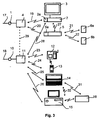
- Fig. 3 shows an embodiment of a communication system, which a Large number of communication devices 2, 3, 4, 5, 6a, 6b, 11, 12, 13, 14, 15, 16 having.
- the communication system shown in FIG. 3 has a first one Signal source 1, which is provided for the distribution of television signals 17, received via cable, satellite or terrestrial.
- the signals 17 of the Signal source 1 are fed to a signal processing device 4 which the Distribution of the signals 17 to communication devices 2, 3, 5 is used.
- the Communication devices 2, 3, 5 are in that shown in Fig. 3 Embodiments of a TV receiver 2 with a receiving device 2a Screen 3, and a radio receiver 5 with a receiving part 5a.
- the transmission of the signals 17 between the signal processing device 4 and the television or radio receiver 2, 5 takes place wirelessly via Radio interfaces 19, 20.
- the signals received by the radio receiver 5 can via further radio interfaces 21, 22, for example as Infrared interfaces are formed, distributed to speakers 6a, 6b.
- the 3 also has a second communication system Signal source 10 for receiving telephone signals 18.
- the telephone signals 18 are fed to a second signal processing device 11, which via Radio interfaces 23 to 26 can be connected to terminals 12 to 16.
- a second signal processing device 11 which via Radio interfaces 23 to 26 can be connected to terminals 12 to 16.
- Communication terminals are the one shown in Fig. 3 Embodiment a telephone set 12, a cordless telephone set 13 portable personal computer 14, and a stationary personal computer 15 with Printer 16 which can be connected via an interface 31 is provided.
- a Connection between stationary personal computer 15 and portable Personal computer 14 is possible via a further interface 32. That in Fig.
- 3 communication system shown also has a dashed line drawn connection possibility between the Signal conditioning devices 4, 11, whereby a connection of the different signal sources 4, 11 is possible. It is also about one Radio interface 28 also a coupling of the TV receiving device 2 to the second signal source 10 is provided.
- the communication system shown in Fig. 3 is based on a decentralized Structure of signal sources 1, 10, i.e. the signal sources 1, 10 and corresponding signal processing devices 4, 11 are with the respective Communication terminals 2, 3, 5 to 12 to 15 directly via the wireless in-house connection connected.
- Such a decentralized structure of the communication system has the advantage that all services of the signal sources 1, 10 at the respective location at which they are used Are available, can be distributed directly without a central Summary must be made into a data stream. This can be a additional cabling to an otherwise necessary central station be avoided.
- the delivery of unnecessary transmission power from the Communication terminals is reduced to a minimum in that the 1, 2, 4, methods used for transmitting power adaptation are provided is. This will send out the data via the radio interfaces Transmission power reduced to a minimum and thus interference from the different communication devices with each other, as well as for the user of the Communication terminals, reduced to a minimum.
- Signal source 1 is, for example, a data source that provides television signals that are supplied to signal processing device 4 via connecting line 17.
- the signal conditioning device 4 is used to decode the television signals supplied by the signal source 1, and to radiate the correspondingly processed television signals to the respective terminals 2, 3, 5.
- the wireless connection of the terminals 2, 3, 5 to the signal conditioning device 4 thus eliminates, for example, within an additional wiring effort for a residential unit.
- the telephone signals supplied by the signal source 10 via the connecting line 18 are transmitted from the second signal processing device 11 to the communication terminals 12 to 15 which can be coupled to the latter.
- the communication terminals such as the personal computer 15, to be connected to a plurality of signal sources 1, 10.
- the communication system shown in FIG. 3 thus has communication terminals which do not access any service, as is the case, for example, with the loudspeakers 6a, 6b shown in FIG. 3 and the printer 16.
- communication terminals are also provided which use only a single service; as is the case for example with the telephone 12, 13.
- the communication system shown in FIG. 1 results in a flexible adaptation to the corresponding signal sources 1, 10.
- the signal processing devices 4, 11 and the communication terminals 2 have direct processing so that the different terminals can have direct access to the different signal sources 1, 10 , 3, 5, 12 to 15 corresponding modems that are used for addressing and logging in and out.
- the transmission power required in each case is only set permanently when these devices are put into operation for the first time, while the transmission power adjustment in the case of communication devices 14, 13 operated in mobile use each time a connection is established and, if appropriate, also continuously the transfer takes place.
- a transmission power adjustment can also be carried out in the event of a change, for example as a result of a newly added communication device.
- a channel access method such as CDMA, DTMA or FDMA or a combination of these methods is used as the transmission method, for example.
- the radio interface 28 between the TV receiving device 2 and the signal processing device 11 for the second signal source 10 makes it possible, for example, to receive fax messages or to access communication services such as the Internet.
- Fig. 4 shows a second embodiment for transmitting a transmission power control signal in two communication devices. The reference symbols already introduced in connection with FIG. 1 are used.
- a test signal 102 is transmitted by a first communication device 100 via an air interface 110. This test signal 102 is received by a second communication device 101.
- a line-bound transmission connection 111 is provided as the “back channel” for transmitting the test signal 103 received by the second communication device to the first communication device 100.
- This is, for example, the power supply network, the antenna network or the telephone network to which both the first communication device 100 and the second communication device 101 are connected.
- the advantage of the method shown in Fig. 4 is that the second Communication device 101 no special transmission device for delivering a wireless transmission signal needed. Rather, it can be based on an existing one Connection line 111 can be used to transmit the received test signal, d. H. of the test signal 103 is used.
- Fig. 5 shows an embodiment of a communication network with a Head station 200 for distributing audio and / or video signals.
- the headend 200 has a receiving device 204, which receives signals Satellite antenna 206 are supplied.
- a control modem 205 is provided, which the distribution of the video and / or Controls audio signals to communication devices 201, 202, 203, 207.
- the basic function of such a head-end station 200 is primarily in the distribution of the television and Audio signals.
- that arranged in the head station 200 serves Modem 205 to control or to adapt the required Transmit power.
- the modem 205 sends the head station 200 for example to the modem of the communication device 201 that is specifically addressable, for example by means of an identification code Test signal.
- This test signal is from the communication device, for example a television 201 or from one with this television 201 coupled modem received and back to the headend 200 sent back. From the degree of correspondence between the sent and again the received test signal becomes a controlled variable for controlling the Transmission power of the modem 205 of the head-end station 200 to supply the modem of the communication device 201.
- the facility is that, for example, an existing cable system may be under Using the power supply network also for controlling the Transmission power adjustment can be used with.
- An adaptation of the transmission power required in each case has the further consequence that, in contrast to uniformly high transmission power interference from also in the Communication network contained further communication devices avoided or be reduced to a minimum.
- the invention thus relates to a method for Adjustment of the transmission power, particularly in the case of communication devices for in-house communication.
- Such communication devices are, for example TV playback devices with reception facilities or Storage devices are coupled.
- To adapt each individually required transmission powers it is proposed that in particular at the beginning a transmission between two communication devices from a connection producing the first communication device, a test pattern is sent, the the remote site, i.e. of the second receiving the test pattern Communication device is sent back. From the degree of agreement from the transmitted and received test signal is derived with which Transmission power the communication devices are operated. This will on the one hand, the energy consumption of the communication devices on each required dimension reduced. In addition, interferences become more neighboring Communication devices minimized. The reduced transmission powers lead also to reduce the so-called electrosmog.
Abstract
Description
Die Erfindung betrifft ein Verfahren zur Sendeleistungsanpassung bei Kommunikationsgeräten, insbesondere bei Geräten der Unterhaltungselektronik.The invention relates to a method for adjusting the transmission power Communication devices, in particular in consumer electronics devices.
Derartige Kommunikationsgeräte kommen beispielsweise bei einem sogenannten "IN-House"-Netz zum Einsatz. Das IN-House-Netz dient der Übertragung von Informationen an verschiedene Kommunikationsgeräte innerhalb eines Hauses, wie beispielsweise Fernsehgerät, Heizung, Raumüberwachung, sowie zwischen diesen.Such communication devices come, for example, from a so-called "IN-House" network in use. The IN-House network is used for the transmission of Information to various communication devices within a house, such as TV, heating, room surveillance, and between this.
Der Erfindung liegt die Aufgabe zugrunde, ein Verfahren zur Sendeleistungsanpassung anzugeben, das auf einfache Weise eine Reduzierung der Sendeleitung ermöglicht.The invention has for its object a method for Specify transmit power adjustment, which is a simple reduction enables the transmission line.
Diese Aufgabe wird durch ein Verfahren zur Sendeleistungsanpassung bei Kommunikationsgeräten insbesondere bei Geräten der Unterhaltungselektronik gelöst, bei dem von einem ersten Kommunikationsgerät ein erstes Testsignal ausgesendet wird, dieses Testsignal von einem zweiten Kommunikationsgerät empfangen und wieder zurückgesendet wird. Im ersten Kommunikationsgerät wird das vom zweiten Kommunikationsgerät empfangene und zurückgesandte Testsignal auf Übereinstimmung mit dem Original untersucht. Aus dem Grad der Übereinstimmung wird eine Regelgröße zur Regelung der Sendeleistung des ersten Kommunikationsgerätes abgeleitet wird.This task is accomplished by a procedure for adjusting the transmission power Communication devices, in particular in consumer electronics devices solved in which a first test signal from a first communication device is emitted, this test signal from a second communication device is received and sent back again. In the first communication device the one received and returned by the second communication device Test signal examined for agreement with the original. From the degree of Agreement becomes a controlled variable for regulating the transmission power of the first communication device is derived.
Der Erfindung liegt die Erkenntnis zugrunde, daß es bei beispielsweise drahtlos miteinander gekoppelten Kommunikationsgeräten häufig nicht erforderlich ist, daß die Kommunikationsgeräte mit einer konstanten, d.h. mit einer relativen hohen, Sendeleistung Signale aussenden. Ein Anwendungsfall besteht beispielsweise darin, daß drahtlos mit einem Fernsehgerät gekoppelte Zusatzlautsprecher in räumlicher Nähe zum Fernsehgerät angeordnet sind. In diesem Fall ist es völlig ausreichend, wenn die Sendeleistung bei der Übertragung der Fernsehtonsignale auf das Nötigste reduziert wird. Hierzu wird vom ersten Kommunikationsgerät, beispielsweise vom Fernsehgerät, bei der Erstinbetriebnahme der Zusatzlautsprecher ein Testsignal ausgesendet. Dieses Testsignal wird vom zweiten Kommunikationsgerät empfangen und wieder ausgesendet. Im Fernsehgerät, d.h. im ersten Kommunikationsgerät erfolgt daraufhin eine Auswertung des empfangenen Testsignals, wobei die Sendeleistung daraufhin in vorgebbaren Schritten solange verringert werden kann, bis die gewünschte Signalqualität gerade noch erreicht wird. Der Vorteil des Verfahrens besteht insbesondere darin, daß die Sendeleistung der Kommunikationsgeräte auf das Nötigste reduziert wird, was zum einen den Energieverbrauch reduziert und zum anderen den Benutzer mit einem Minimum an HF-Energie belastet und somit zu einer Reduzierung des Phänomens "Elektrosmogs" führt. Bei dem Betrieb mehrerer Kommunikationsgeräte innerhalb eines Hauses oder in benachbarten Wohneinheiten wird darüberhinaus eine Störung der jeweiligen Kommunikationsgeräte vermieden bzw. zumindest reduziert.The invention is based on the finding that it is wireless, for example coupled communication devices is often not required that the communication devices with a constant, i.e. with a relatively high, Send out power signals. There is one application, for example in that additional speakers wirelessly coupled to a television in are arranged in close proximity to the television set. In this case, it is complete sufficient if the transmission power in the transmission of television sound signals is reduced to the bare minimum. For this purpose, the first communication device, for example, from the television, when the Additional speakers sent a test signal. This test signal is from second communication device received and sent again. in the Television, i.e. There then takes place in the first communication device Evaluation of the received test signal, the transmission power then in Predefinable steps can be reduced until the desired Signal quality is just reached. The advantage of the procedure is there in particular in that the transmission power of the communication devices on the Necessary is reduced, which on the one hand reduces energy consumption and on the other others burdened the user with a minimum of RF energy and thus too leads to a reduction in the phenomenon of "electrosmog". When operating several communication devices within a house or in neighboring ones Housing units will also disrupt the respective Communication devices avoided or at least reduced.
Eine wirksame Anpassung der jeweils erforderlichen Sendeleistung, angepaßt an die jeweils herrschenden Betriebverhältnisse wie z. B. Entfernung zwischen den Kommunikationsgeräten etc., kann auf einfache Weise dadurch erreicht werden, daß die Sendeleistung solange verringert wird, bis der Grad der Übereinstimmung einen vorgebbaren Grenzwert nicht unterschreitet.An effective adaptation of the transmission power required in each case, adapted to the prevailing operating conditions such. B. Distance between Communication devices etc. can be easily achieved by that the transmission power is reduced until the degree of agreement does not fall below a predefinable limit.
Bei einem stationären Betrieb der miteinander zu verbindenenden Kommunikationsgeräte ist es in der Regel ausreichend, daß die Sendeleistungsanpassung einmalig bei Erstinbetriebnahme einer aus stationären Kommunikationsgeräten bestehenden Kommunikationsgerätekonfiguration erfolgt.In stationary operation, the ends to be connected Communication devices, it is usually sufficient that the One-time transmission power adjustment when commissioning one of stationary Communication devices existing communication device configuration takes place.
Eine Einbindung weiterer Kommunikationsgeräte ist auf einfache Weise dadurch möglich, daß die Sendeleistungsanpassung auch bei einem zusätzlich hinzukommenden Kommunikationsgerät erfolgt. Die Veränderung von Betriebsbedingungen, wie beispielsweise veränderte Leitungswiderstände bei leitungsgebundener Übertragung, kann dadurch berücksichtigt werden, daß die Sendeleistungsanpassung in vorgebbaren Zeitabständen erfolgt.This makes it easy to integrate additional communication devices possible that the transmission power adjustment even with an additional additional communication device takes place. The change from Operating conditions, such as changes in line resistance wired transmission, can be taken into account that the Transmission power adjustment takes place at predefinable time intervals.
Bei an verschiedenen Standorten zu betreibenden Kommunikationsgeräten oder bei mobilem Betrieb ist es vorteilhaft, daß die aktuell erforderliche Sendeleistung kontinuierlich in Abhängigkeit des jeweils ermittelten Grades der Übereinstimmung des gesendeten zum wieder empfangenen Testsignals ermittelt und eingestellt wird.For communication devices to be operated at different locations or with mobile operation it is advantageous that the currently required transmission power continuously depending on the determined degree of agreement of the transmitted to received test signal determined and set becomes.
Eine Störung der Nutzdatenübertragung durch das Testsignal kann auf einfache Weise dadurch vermieden werden, daß die Sendeleistungsanpassung zu Beginn einer Verbindungsaufnahme vor Beginn einer Übertragung von Nutzdaten oder parallel hierzu zwischen dem ersten und dem zweiten Kommunikationsgerät erfolgt. A disturbance in the useful data transmission by the test signal can easily be Way avoided in that the transmission power adjustment at the beginning establishing a connection before the start of a transmission of user data or in parallel between the first and the second communication device he follows.
Der Einsatz des Verfahrens zur Sendeleistungsanpassung ist besonders in den Fällen geeignet, wenn das erste Kommunikationsgerät eine Signalaufbereitungseinrichtung zur Aufbereitung von analogen und/oder digitalen Ton- und/oder Bildsignalen, insbesondere von Rundfunk-, Fernseh- und/oder Telefonsignalen aufweist und das zweite Kommunikationsgerät ein Teilnehmergerät an von der Signalaufbereitungseinrichtung zur Verfügung stehenden Dienste ist.The use of the method for adapting the transmission power is particularly in the Suitable cases when the first communication device Signal processing device for processing analog and / or digital Sound and / or image signals, in particular from radio, television and / or Has telephone signals and the second communication device Subscriber device available from the signal processing device standing services.
Besonders geeignete Anwendungsfälle des Verfahrens sind, daß das erste und das zweite Kommunikationsgerät über eine drahtlose oder eine drahtgebundene bidirektionale Verbindung miteinander koppelbar sind.Particularly suitable applications of the method are that the first and the second communication device via a wireless or a wired bidirectional connection can be coupled.
Je nach vorhandener Infrastruktur und Art des Kommunikationsgerät kann die Übertragung des Testsignals vom ersten Kommunikationsgerät über ein erstes Übertragungsmedium, insbesondere ein drahtloses Übertragungsmedium erfolgen, während die Rückübertragung des Testsignals vom zweiten Kommunikationsgerät zum ersten Kommunikationsgerät über ein zweites Übertragungsmedium, insbesondere ein drahtgebundenes Übertragungsmedium erfolgen kann.Depending on the existing infrastructure and type of communication device, the Transmission of the test signal from the first communication device via a first Transmission medium, in particular a wireless transmission medium take place during the retransmission of the test signal from the second Communication device to the first communication device via a second Transmission medium, in particular a wired transmission medium can be done.
Im folgenden wird die Erfindung anhand der in den Figuren dargestellten Ausführungsbeispiele näher beschrieben und erläutert.In the following, the invention is illustrated by the figures Exemplary embodiments described and explained in more detail.
Es zeigen:
- Fig. 1
- ein erstes Ausführungsbeispiel zur Übertragung eines Sendeleitungsregelsignals mit zwei Kommunikationsgeräten,
- Fig. 2
- ein Blockschaltbild mit einer Prinzipdarstellung der Erzeugung eines Sendeleitungsregelsignals,
- Fig. 3
- ein Ausführungsbeispiel eines Kommunikationsnetzes,
- Fig. 4
- ein zweites Ausführungsbeispiel zur Übertragung eines Sendeleitungsregelsignals mit zwei Kommunikationsgeräten und
- Fig. 5
- ein weiteres Ausführungsbeispiel eines Kommunikationsnetzes mit einer Kopfstation zur Verteilung von Medien und/oder Videosignalen.
- Fig. 1
- 1 shows a first exemplary embodiment for transmitting a transmission line control signal with two communication devices,
- Fig. 2
- 2 shows a block diagram with a basic illustration of the generation of a transmission line control signal,
- Fig. 3
- an embodiment of a communication network,
- Fig. 4
- a second embodiment for transmitting a transmission line control signal with two communication devices and
- Fig. 5
- a further embodiment of a communication network with a head-end station for distributing media and / or video signals.
Fig. 1 zeigt ein erstes Ausführungsbeispiel zur Sendeleistungsreduzierung zweier
Kommunikationsgeräte 100, 101. Das erste Kommunikationsgerät 100 sendet ein
Testsignal 102 aus, das von einem zweiten Kommunikationsgerät 101 empfangen
wird. Das zweite Kommunikationsgerät 101 wird in der empfangenen Weise das
Testsignal 103, welches das empfangenen Testsignal 102 ist, unverändert wie das
Testsignal 102 empfangen wurde, an das erste Kommunikationsgerät 100
zurückgesendet.1 shows a first exemplary embodiment for reducing the transmission power of two
Wie im Zusammenhang mit Fig. 2 noch erläutert wird, wird im ersten
Kommunikationsgerät 100 das empfangene Testsignal 103 auf Übereinstimmung
mit dem Original, d.h. mit dem Testsignal 102 geprüft und aus dem Grad der
Übereinstimmung eine Anpassung der Sendeleistung vorgenommen. Die
Sendeleistung des Kommunikationsgerätes 100 wird solange verringert, bis der
Grad der Übereinstimmung einen einstellbaren Grenzwert erreicht. Im Mobilbetrieb
der Kommunikationsgeräte 100, 101 kann eine Anpassung der Sendeleistung
parallel zur Übertragung von Nutzsignalen kontinuierlich erfolgen. Bei stationär
betriebenen Kommunikationsgeräten 100, 101 ist es in der Regel ausreichend,
wenn die Einstellung einer Sendeleistung bei der Erstinbetriebnahme der
Kommunikationsgeräte 100, 101 durchgeführt wird.As will be explained in connection with FIG. 2, the
Fig. 2 zeigt ein Blockschaltbild mit einer Prinzipdarstellung zur Erzeugung eines
Sendeleistungsregelsignals 109. Die in Fig. 2 dargestellten Teile des
Blockschaltbilds sind beispielsweise in dem in Fig. 1 dargestellten
Kommunikationsgerät 100 integriert. Im einzelnen weist das in Fig. 2 dargestellte
Blockschaltbild einen Testmustergenerator 104 auf, der ein Testsignal 102 an eine
Sendeeinrichtung 105 sowie an einen Grenzwertvergleicher 108 weiterleitet. Der
Grenzwertvergleicher 108 ist als Komparator ausgebildet. Das Ergebnis des
Komparators wird einer Bewertungseinheit zugeführt, welche die Qualität des
empfangenen Testsignals 103 zum Original-Testsignal 102 bewertet. Die
Sendeeinrichtung 105 ist mit einer Sende-Empfangsantenne 106 verbunden.
Darüber hinaus ist eine Empfangseinrichtung 107 vorgesehen, die ebenfalls mit
der Sende-Empfangsantenne 106 gekoppelt ist. Die Empfangseinrichtung 107
empfängt ein von einem zweiten Kommunikationsgerät (vgl. Fig. 1) ans
Kommunikationsgerät 100 zurückgesendetes Testsignal 103, welches der
Vergleichseinrichtung 108 zugeführt wird. Am Ausgang der Vergleichseinrichtung
108 wird eine Regelgröße 109 gebildet, die der Einstellung der Sendeleistung der
Sendeeinrichtung 105 dient. Als Sendeeinrichtung 105 kann ein im
Kommunikationsgerät 100 ohnehin für Nutzsignalübertragungen vorhandener
Nutzsignalsender verwendet werden. Gleiches gilt für die Empfangseinrichtung
107.Fig. 2 shows a block diagram with a schematic diagram for generating a
Transmitting
Anstelle einer Anbindung an eine Sende-Empfangsantenne 106 kann bei
drahtgebundenen Übertragungen auch ein Anschluß an ein drahtgebundenes
Übertragungsmedium vorgesehen sein. Der Testsignalgenerator 104 kann ein
Digitalsignal oder, je nach Anwendungsfall, auch ein analoges Testsignal
erzeugen. Das vom Testsignalgenerator 104 erzeugte Testsignal 102 wird, ggfs. in
Verbindung mit einem Kennungssignal zur eigenen und/oder zur Identifizierung
einer gerufenen Gegenstelle, d.h. zu einem zweiten Kommunikationsgerät, mit
dem ein Verbindungsaufbau erfolgen soll, übertragen. Von dieser Gegenstelle,
d.h. vom zweiten Kommunikationsgerät, wird dieses Testsignal empfangen und
wieder, ggfs. ebenfalls mit einer entsprechenden Kennung des ersten
Kommunikationsgerät, von dem das Testsignal 102 gesendet wurde
zurückgesendet. Im ersten Kommunikationsgerät wird das empfangene Testsignal
103 auf Übereinstimmung mit dem ursprünglich gesendeten Testsignal 102
überprüft. Hierzu dient die Vergleichseinrichtung 108, in der ein Grenzwert bzw.
ein Kriterium gespeichert ist, welches das Minimum der geforderten
Empfangsqualität kennzeichnet. In einer vorteilhaften Ausgestaltung der Erfindung
ist die Vergleichseinrichtung 108 derart ausgeführt, daß zunächst ein Soll-Ist-Vergleich
durchgeführt wird, anschließend wird ein Vergleich der Abweichung mit
einem vorgegebenen Grenzwert vorgenommen. Abhängig vom Grad dieser
Übereinstimmung des Testsignals 102, sowie des Testsignals 103, wird mit Hilfe
der von der Vergleichseinrichtung 108 gelieferten Regelgröße 109 die
Sendeleistung der Sendeeinrichtung 105 angepaßt. Mit Hilfe des
erfindungsgemäßen Verfahrens wird erreicht, daß leistungsschwächere oder
weiter entferntere Modems oder Sendeeinrichtungen nicht durch stärkere oder in
unmittelbarer Nähe befindliche Modems oder Sendeeinrichtungen "übertönt" oder
"überfahren" werden. Darüber hinaus wird vermieden, daß durch hohe
Übertragungspegel die Eingangsempfindlichkeit des Empfängers 107 durch
Ansprechen beispielsweise einer automatischen Verstärkungsregelung
herabgesetzt wird, was wiederum beim Empfang von Signal mit einem
schwächeren Pegel nachteilig wäre.Instead of a connection to a
Fig. 3 zeigt ein Ausführungsbeispiel eines Kommunikationssystems, welches eine
Vielzahl von Kommunikationsgeräten 2, 3, 4, 5, 6a, 6b, 11, 12, 13, 14, 15, 16
aufweist. Das in Fig. 3 dargestellte Kommunikationssystem weist eine erste
Signalquelle 1 auf, welche zur Verteilung von Fernsehsignalen 17 vorgesehen ist,
die über Kabel, Satellit oder terrestrisch empfangen werden. Die Signale 17 der
Signalquelle 1 werden einer Signalaufbereitungseinrichtung 4 zugeführt, die der
Verteilung der Signale 17 an Kommunikationsgeräte 2, 3, 5, dient. Die
Kommunikationsgeräte 2, 3, 5 sind bei dem in Fig. 3 dargestellten
Ausführungsbeispielen ein TV-Empfänger 2 mit einer Empfangseinrichtung 2a, ein
Bildschirm 3, sowie eine Rundfunkempfangseinrichtung 5 mit einem Empfangsteil
5a. Die Übertragung der Signale 17 zwischen der Signalaufbereitungseinrichtung
4 und dem Fernseh- bzw. Rundfunkempfänger 2, 5 erfolgt dabei drahtlos über
Funkschnittstellen 19, 20. Die vom Rundfunkempfänger 5 empfangenen Signale
können über weitere Funkschnittstellen 21, 22, die beispielsweise als
Infrarotschnittstellen ausgebildet sind, an Lautsprecher 6a, 6b verteilt werden. Das
in Fig.3 dargestellte Kommunikationssystem weist darüber hinaus eine zweite
Signalquelle 10 zum Empfang von Telefonsignalen 18 auf. Die Telefonsignale 18
werden einer zweiten Signalaufbereitungseinrichtung 11 zugeführt, die über
Funkschnittstellen 23 bis 26 mit Endgeräten 12 bis 16 verbindbar sind. Als
Kommunikationsendgeräte sind bei dem in Fig. 3 dargestellten
Ausführungsbeispiel ein Telefonapparat 12, ein schnurloser Telefonapparat 13, ein
tragbarer Personalcomputer 14, sowie ein stationärer Personalcomputer 15 mit
über eine Schnittstelle 31 anschließbaren Drucker 16 vorgesehen. Eine
Verbindung zwischen stationären Personalcomputer 15 und tragbaren
Personalcomputer 14 ist über eine weitere Schnittstelle 32 möglich. Das in Fig. 3
dargestellte Kommunikationssystem weist darüber hinaus eine gestrichelt
eingezeichnete Verbindungsmöglichkeit zwischen den
Signalaufbereitungseinrichtungen 4, 11 auf, wodurch eine Verbindung der
verschiedenen Signalquellen 4, 11 möglich wird. Außerdem ist über eine
Funkschnittstelle 28 auch eine Kopplung der TV-Empfangseinrichtung 2 an die
zweite Signalquelle 10 vorgesehen. Fig. 3 shows an embodiment of a communication system, which a
Large number of
Das in Fig. 3 dargestellte Kommunikationssystem beruht auf einer dezentralen
Struktur der Signalquellen 1, 10, d.h. die Signalquellen 1, 10 bzw. die
entsprechenden Signalaufbereitungseinrichtungen 4, 11 sind mit den jeweiligen
Kommunikationsendgeräten 2, 3, 5 bis 12 bis 15 direkt über die drahtlose Inhouse-Verbindung
verbunden.The communication system shown in Fig. 3 is based on a decentralized
Structure of
Eine derartige dezentrale Struktur des Kommunikationssystems hat den Vorteil,
daß alle Dienste der Signalquellen 1, 10 am jeweiligen Ort, an welchem diese zur
Verfügung stehen, direkt verteilt werden können, ohne daß eine zentrale
Zusammenfassung zu einem Datenstrom erfolgen muß. Hierdurch kann ein
zusätzlicher Verkabelungsaufwand zu einer ansonsten notwendigen Zentralstation
vermieden werden. Die Abgabe unnötiger Sendeleistungen der
Kommunikationsendgeräte wird dadurch auf ein Minimum reduziert, daß das in
den Fig.1, 2, 4 angewendete Verfahren zur Sendeleistungsanpassung vorgesehen
ist. Hierdurch werden die über die Funkschnittstellen auszusendenden
Sendeleistungen auf ein Minimum reduziert und somit Störeinflüsse der
verschiedenen Kommunikationsgeräte untereinander, sowie für den Benutzer der
Kommunikationsendgeräte, auf ein Minimum reduziert.Such a decentralized structure of the communication system has the advantage
that all services of the
Bei der Signalquelle 1 handelt es sich beispielsweise um eine Datenquelle, die
Fernsehsignale bereitstellt, die über die Verbindungsleitung 17 an die
Signalaufbereitungseinrichtung 4 geliefert werden. Die
Signalaufbereitungseinrichtung 4 dient zur Decodierung der von der Signalquelle 1
gelieferten Fernsehsignale, sowie zur Abstrahlung der entsprechend aufbereiteten
Fernsehsignale an die jeweiligen Endgeräte 2, 3, 5. Durch die drahtlose
Anbindung der Endgeräte 2, 3, 5 an die Signalaufbereitungseinrichtung 4 entfällt
somit beispielsweise innerhalb einer Wohneinheit ein zusätzlicher
Verkabelungsaufwand. In entsprechender Weise werden die von der Signalquelle
10 über die Verbindungsleitung 18 gelieferten Telefonsignale von der zweiten
Signalaufbereitungseinrichtung 11 an die mit dieser koppelbaren
Kommunikationsendgeräte 12 bis 15 übermittelt. Über eine Verbindungsleitung 19
bzw. durch direkte Anbindung an die jeweilige Signalaufbereitungseinrichtung ist
es auch möglich, daß bestimmte Kommunikationsendgeräte, wie beispielsweise
der Personalcomputer 15, mit mehreren Signalquellen 1, 10, in Verbindung steht.
Hierdurch wird es beispielsweise möglich, daß der Personalcomputer 15 auf
Signale aus der Signalquelle 1 empfangen kann. Somit weist das in Fig. 3
dargestellte Kommunikationssystem Kommunikationsendgeräte auf, die auf keinen
Dienst zugreifen, wie dies beispielsweise bei den in Fig. 3 dargestellten
Lautsprechern 6a, 6b, sowie dem Drucker 16, der Fall ist. Darüber hinaus sind
auch Kommunikationsendgeräte vorgesehen, welche lediglich einen einzigen
Dienst nutzen; wie dies beispielsweise bei dem Telefon 12, 13 der Fall ist.
Insgesamt entsteht durch das in Fig.1 dargestellte Kommunikationssystem eine
flexible Anpassung an die entsprechenden Signalquellen 1, 10. Damit ein direkter
paralleler Zugriff der verschiedenen Endgeräte auf die unterschiedlichen
Signalquellen 1, 10 möglich ist, weisen die Signalaufbereitungseinrichtungen 4, 11,
sowie die Kommunikationsendgeräte 2, 3, 5, 12 bis 15 entsprechende Modems auf,
die der Adressierung sowie der An- bzw. Abmeldung dienen. Die jeweils
benötigten Sendeleistungen werden bei stationär betriebenen
Kommunikationsgeräten, wie beispielsweise der Fernsehempfangseinrichtung 2
sowie der Rundfunkempfangseinrichtung 5 lediglich bei der Erstinbetriebnahme
dieser Geräte fest eingestellt, während die Sendeleistungsanpassung bei im
mobilen Einsatz betriebenen Kommunikationsgeräten 14, 13 jeweils bei einem
Verbindungsaufbau und ggfs. auch kontinuierlich während der Übertragung erfolgt.
Auch bei einer Anderung, beispielsweise durch ein neu hinzukommendes
Kommunikationsgerät, kann eine Sendeleistungsanpassung durchgeführt werden.
Als Übertragungsverfahren kommt beispielsweise ein Kanalzugriffsverfahren, wie
CDMA, DTMA oder FDMA bzw. eine Kombination dieser Verfahren zum Einsatz.
Über die Funkschnittstelle 28 zwischen TV-Empfangseinrichtung 2 und
Signalaufbereitungseinrichtung 11 für die zweite Signalquelle 10 ist beispielsweise
ein Empfang von Telefaxnachrichten oder ein Zugriff auf Kommunikationsdienst
wie beispielsweise das Internet möglich.
Fig. 4 zeigt ein zweites Ausführungsbeispiel zur Übertragung eines
Sendeleistungsregelsignals bei zwei Kommunikationsgeräten. Dabei werden die
bereits im Zusammenhang mit Fig.1 eingeführten Bezugszeichen verwendet. Bei
dem in Fig. 4 dargestellten Ausführungsbeispiel wird von einem ersten
Kommunikationsgerät 100 über eine Luftschnittstelle 110 ein Testsignal 102
ausgesendet. Dieses Testsignal 102 wird von einem zweiten
Kommunikationsgerät 101 empfangen. Als ''Rückkanal'' zur Übertragung des vom
zweiten Kommunikationsgerät empfangenen Testsignals 103 an das erste
Kommunikationsgerät 100 ist eine leitungsgebundene Übertragungsverbindung
111 vorgesehen. Dabei handelt es sich beispielsweise um das
Stromversorgungsnetz, das Antennennetz oder das Telefonnetz, an das sowohl
das erste Kommunikationsgerät 100, als auch das zweite Kommunikationsgerät
101 angeschlossen sind.Signal
Fig. 4 shows a second embodiment for transmitting a transmission power control signal in two communication devices. The reference symbols already introduced in connection with FIG. 1 are used. In the exemplary embodiment shown in FIG. 4, a
Vorteil des in Fig. 4 dargestellten Verfahrens ist, daß das zweite
Kommunikationsgerät 101 keine spezielle Sendeeinrichtung zur Abgabe eines
drahtlosen Sendesignals benötigt. Vielmehr kann auf eine ohnehin bestehende
Verbindungsleitung 111 zurückgegriffen werden, die zur Übertragung des
empfangenen Testsignals, d. h. des Testsignals 103 verwendet wird.The advantage of the method shown in Fig. 4 is that the
Fig. 5 zeigt ein Ausführungsbeispiel eines Kommunikationsnetzes mit einer
Kopfstation 200 zur Verteilung von Audio- und/oder Videosignalen. Die Kopfstation
200 weist eine Empfangseinrichtung 204 auf, der Empfangssignale einer
Satellitenantenne 206 zugeführt werden. Darüber hinaus ist in der Kopfstation 200
ein Steuermodem 205 vorgesehen, das die Verteilung der Video- und/oder
Audiosignale an Kommunikationsgeräte 201, 202, 203, 207 steuert. Fig. 5 shows an embodiment of a communication network with a
Die grundsätzliche Funktion einer derartigen Kopfstation 200 besteht vor allem in
der Verteilung der mittels der Antenne 206 empfangenen Fernseh- und
Audiosignale. Darüber hinaus dient das in der Kopfstation 200 angeordnete
Modem 205 zur Steuerung bzw. zur Anpassung der jeweils erforderlichen
Sendeleistungen. Hierzu sendet das Modem 205 der Kopfstation 200
beispielsweise an das Modem des Kommunikationsgerätes 201, das
beispielsweise mittels eines Identifikationscodes gezielt adressierbar ist, ein
Testsignal. Dieses Testsignal wird von dem Kommunikationsgerät, beispielsweise
einem Fernsehgerät 201 bzw. von einem mit diesem Fernsehgerät 201
gekoppelten Modem empfangen und wieder an die Kopfstation 200
zurückgesendet. Aus dem Grad der Übereinstimmung zwischen dem gesendeten
und wieder empfangenen Testsignal wird eine Regelgröße zur Regelung der
Sendeleistung des Modems 205 der Kopfstation 200 zur Versorgung des Modems
des Kommunikationsgeräts 201 abgeleitet. Vorteil der in Fig. 5 dargestellten
Einrichtung ist es, daß beispielsweise ein bestehendes Kabelsystem ggf. unter
Zuhilfenahme des Stromversorgungsnetzes auch für eine Steuerung der
Sendeleistunganpassung mit verwendet werden kann. Eine Anpassung der
jeweilig benötigten Sendeleistungen hat weiterhin zur Folge, daß im Gegensatz zu
gleichmäßig hohen Sendeleistungen Störungen von ebenfalls im
Kommunikationsnetz enthaltenen weiteren Kommunikationsgeräten vermieden
bzw. auf ein Minimum reduziert werden.The basic function of such a head-
Zusammenfassend betrifft die Erfindung somit ein Verfahren zur Sendeleistungsanpassung insbesondere bei Kommunikationsgeräten der In-House-Kommunikation. Derartige Kommunikationsgeräte sind beispielsweise Fernsehwiedergabegeräte, die mit Empfangseinrichtungen oder Speichereinrichtungen gekoppelt sind. Zur Anpassung der jeweils individuell benötigten Sendeleistungen wird vorgeschlagen, daß insbesondere zu Beginn einer Übertragung zwischen zwei Kommunikationsgeräten vom eine Verbindung herstellenden ersten Kommunikationsgerät ein Testmuster gesendet wird, das von der Gegenstelle, d.h. von dem das Testmuster empfangenden zweiten Kommunikationsgerät zurückgesendet wird. Aus dem Grad der Übereinstimmung von gesendetem und wieder empfangenem Testsignal wird abgeleitet, mit welcher Sendeleistung die Kommunikationsgeräte betrieben werden. Hierdurch wird einerseits der Energieverbrauch der Kommunikationsgeräte auf das jeweils erforderliche Maß reduziert. Darüber hinaus werden Störeinflüsse benachbarter Kommunikationsgeräte minimiert. Die verringerten Sendeleistungen führen außerdem zu einer Verringerung des sogenannten Elektrosmogs.In summary, the invention thus relates to a method for Adjustment of the transmission power, particularly in the case of communication devices for in-house communication. Such communication devices are, for example TV playback devices with reception facilities or Storage devices are coupled. To adapt each individually required transmission powers, it is proposed that in particular at the beginning a transmission between two communication devices from a connection producing the first communication device, a test pattern is sent, the the remote site, i.e. of the second receiving the test pattern Communication device is sent back. From the degree of agreement from the transmitted and received test signal is derived with which Transmission power the communication devices are operated. This will on the one hand, the energy consumption of the communication devices on each required dimension reduced. In addition, interferences become more neighboring Communication devices minimized. The reduced transmission powers lead also to reduce the so-called electrosmog.
Claims (10)
dadurch gekennzeichnet,
daß die Sendeleistung solange verringert wird, bis der Grad der Übereinstimmung zwischen dem gesendeten Testsignal (102) und dem empfangenen Testsignal (103) einen vorgebbaren Grenzwert nicht unterschreitet.Method according to claim 1,
characterized,
that the transmission power is reduced until the degree of correspondence between the transmitted test signal (102) and the received test signal (103) does not fall below a predefinable limit.
dadurch gekennzeichnet,
daß die Sendeleistungsanpassung einmalig bei Erstinbetriebnahme einer aus stationären Kommunikationsgeräten (100, 101) bestehende Kommunikationsgerätekonfiguration erfolgt. Method according to one of claims 1 or 2,
characterized,
that the transmission power is adjusted once when a communication device configuration consisting of stationary communication devices (100, 101) is put into operation for the first time.
dadurch gekennzeichnet,
daß die Sendeleistungsanpassung bei einem zusätzlich hinzukommenden Kommunikationsgerät und/oder in vorgebbaren Zeitabständen erfolgt.Method according to one of claims 1 to 3,
characterized,
that the transmission power is adjusted with an additional communication device and / or at predefinable time intervals.
dadurch gekennzeichnet,
daß die aktuell erforderliche Sendeleistung kontinuierlich in Abhängigkeit des jeweils ermittelten Grades der Übereinstimmung des gesendeten Testsignals (102) und des empfangenen Testsignals (103) ermittelt und eingestellt wird.Method according to one of claims 1 to 4,
characterized,
that the currently required transmission power is continuously determined and set as a function of the degree of correspondence between the test signal (102) and the test signal (103) received.
dadurch gekennzeichnet,
daß die Sendeleistungsanpassung zu Beginn einer Verbindungsaufnahme vor Beginn einer Übertragung von Nutzdaten oder parallel hierzu zwischen dem ersten (100) und dem zweiten Kommunikationsgerät (101) erfolgt.Method according to one of claims 1 to 5,
characterized,
that the transmission power is adjusted at the start of a connection before the start of a transmission of user data or in parallel therewith between the first (100) and the second communication device (101).
dadurch gekennzeichnet,
daß das erste Kommunikationsgerät (100) eine Signalaufbereitungseinrichtung (4, 11) zur Aufbereitung von analogen und/oder digitalen Ton- und/oder Bildsignalen, insbesondere von Rundfunk-, Fernseh- und/oder Telefonsignalen aufweist und daß das zweite Kommunikationsgerät (101) ein Teilnehmergerät an von der Signalaufbereitungseinrichtung (4, 11) zur Verfügung stehenden Dienste ist. Method according to one of claims 1 to 6,
characterized,
that the first communication device (100) has a signal processing device (4, 11) for processing analog and / or digital audio and / or video signals, in particular radio, television and / or telephone signals, and that the second communication device (101) has a Subscriber device for services available from the signal processing device (4, 11).
dadurch gekennzeichnet,
daß das erste Kommunikationsgerät (100) und das zweite Kommunikationsgerät (101) über eine drahtlose oder eine drahtgebundene bidirektionale Verbindung miteinander koppelbar sind.Method according to one of claims 1 to 7,
characterized,
that the first communication device (100) and the second communication device (101) can be coupled to one another via a wireless or a wired bidirectional connection.
dadurch gekennzeichnet,
daß die Übertragung des Testsignals (102) vom ersten Kommunikationsgerät (100) über ein erstes Übertragungsmedium, insbesondere ein drahtloses Übertragungsmedium (110) erfolgt und daß die Rückübertragung des Testsignals (103) vom zweiten Kommunikationsgerät (101) zum ersten Kommunikationsgerät (100) über ein zweites Übertragungsmedium (111), insbesondere ein drahtgebundenes Übertragungsmedium erfolgt.Method according to one of claims 1 to 8,
characterized,
that the test signal (102) is transmitted from the first communication device (100) via a first transmission medium, in particular a wireless transmission medium (110) and that the test signal (103) is retransmitted from the second communication device (101) to the first communication device (100) via a second transmission medium (111), in particular a wired transmission medium.
Applications Claiming Priority (2)
| Application Number | Priority Date | Filing Date | Title |
|---|---|---|---|
| DE19803849A DE19803849A1 (en) | 1998-01-31 | 1998-01-31 | Adjustment of transmission power, especially for wireless in-house communication |
| DE19803849 | 1998-01-31 |
Publications (3)
| Publication Number | Publication Date |
|---|---|
| EP0933884A2 true EP0933884A2 (en) | 1999-08-04 |
| EP0933884A3 EP0933884A3 (en) | 2001-08-16 |
| EP0933884B1 EP0933884B1 (en) | 2006-08-16 |
Family
ID=7856289
Family Applications (1)
| Application Number | Title | Priority Date | Filing Date |
|---|---|---|---|
| EP99101174A Expired - Lifetime EP0933884B1 (en) | 1998-01-31 | 1999-01-22 | Transmission power adjustment particularly for wireless in-house communication |
Country Status (4)
| Country | Link |
|---|---|
| EP (1) | EP0933884B1 (en) |
| AT (1) | ATE336831T1 (en) |
| DE (2) | DE19803849A1 (en) |
| ES (1) | ES2272019T3 (en) |
Families Citing this family (3)
| Publication number | Priority date | Publication date | Assignee | Title |
|---|---|---|---|---|
| DE19949918B4 (en) * | 1999-10-16 | 2005-09-15 | Grundig Multimedia B.V. | Wireless digital audio transmission in the home area |
| DE102007049288A1 (en) * | 2007-10-12 | 2009-04-30 | Dernedde, Niels | Biocompatible, wireless remote operation method for home areas, involves providing components with current saving circuit, switching components in continuous and quasi continuous manner and sending instructions as wireless signal |
| DE102007053330B4 (en) * | 2007-11-08 | 2019-01-31 | Blum-Novotest Gmbh | Method for regulating the transmitting power of a transmitting / receiving device in a position measuring system for a machine and transceiver device |
Citations (5)
| Publication number | Priority date | Publication date | Assignee | Title |
|---|---|---|---|---|
| US4567485A (en) * | 1981-11-16 | 1986-01-28 | Nippon Electric Co., Ltd. | Earth station transmission power control system for keeping an EIRP of down link signals constant irrespective of weather |
| JPH04144317A (en) * | 1990-10-04 | 1992-05-18 | Nec Corp | Transmission power control system for satellite communication earth station |
| US5220678A (en) * | 1991-08-12 | 1993-06-15 | Motorola, Inc. | Method and apparatus for adjusting the power of a transmitter |
| DE4242705A1 (en) * | 1992-12-17 | 1994-06-23 | Nbb Nachrichtentech Gmbh | Bidirectional operating procedure for radio transceiver |
| WO1997049197A1 (en) * | 1996-06-17 | 1997-12-24 | Nokia Mobile Phones Limited | Control of transmission power in wireless packet data transfer |
-
1998
- 1998-01-31 DE DE19803849A patent/DE19803849A1/en not_active Ceased
-
1999
- 1999-01-22 ES ES99101174T patent/ES2272019T3/en not_active Expired - Lifetime
- 1999-01-22 EP EP99101174A patent/EP0933884B1/en not_active Expired - Lifetime
- 1999-01-22 DE DE59913770T patent/DE59913770D1/en not_active Expired - Lifetime
- 1999-01-22 AT AT99101174T patent/ATE336831T1/en not_active IP Right Cessation
Patent Citations (5)
| Publication number | Priority date | Publication date | Assignee | Title |
|---|---|---|---|---|
| US4567485A (en) * | 1981-11-16 | 1986-01-28 | Nippon Electric Co., Ltd. | Earth station transmission power control system for keeping an EIRP of down link signals constant irrespective of weather |
| JPH04144317A (en) * | 1990-10-04 | 1992-05-18 | Nec Corp | Transmission power control system for satellite communication earth station |
| US5220678A (en) * | 1991-08-12 | 1993-06-15 | Motorola, Inc. | Method and apparatus for adjusting the power of a transmitter |
| DE4242705A1 (en) * | 1992-12-17 | 1994-06-23 | Nbb Nachrichtentech Gmbh | Bidirectional operating procedure for radio transceiver |
| WO1997049197A1 (en) * | 1996-06-17 | 1997-12-24 | Nokia Mobile Phones Limited | Control of transmission power in wireless packet data transfer |
Non-Patent Citations (1)
| Title |
|---|
| PATENT ABSTRACTS OF JAPAN vol. 016, no. 420 (E-1259), 4. September 1992 (1992-09-04) & JP 04 144317 A (NEC CORP), 18. Mai 1992 (1992-05-18) * |
Also Published As
| Publication number | Publication date |
|---|---|
| ATE336831T1 (en) | 2006-09-15 |
| EP0933884B1 (en) | 2006-08-16 |
| DE19803849A1 (en) | 1999-08-05 |
| DE59913770D1 (en) | 2006-09-28 |
| ES2272019T3 (en) | 2007-04-16 |
| EP0933884A3 (en) | 2001-08-16 |
Similar Documents
| Publication | Publication Date | Title |
|---|---|---|
| DE60105429T2 (en) | RECEIVER | |
| DE60222276T2 (en) | SOFTWARE-CONTROLLED BIDIRECTIONAL MULTI-MODE COMMUNICATION DEVICE | |
| DE19802226A1 (en) | Multimedia input / control device and method for multimedia communication | |
| DE10236679A1 (en) | Wireless video display device and method | |
| DE69820604T2 (en) | METHOD AND DEVICE OF A RADIO COMMUNICATION SYSTEM WITH A FREQUENCY REUSE SYSTEM | |
| DE19802103A1 (en) | Power control method for radio signals depending on frequency and temperature changes in a call transmitter | |
| WO2011020838A1 (en) | Digital wireless audio transmission system and method for wireless audio transmission | |
| DE2027888B2 (en) | Wireless system | |
| EP1004214A2 (en) | Method, mobile station and telecommunication system for generating an adaptation to a process for accessing a radio interface supported by a mobile radiotelephone network | |
| EP0933884B1 (en) | Transmission power adjustment particularly for wireless in-house communication | |
| WO1996019052A2 (en) | Circuit array and process for creating a data feedback channel from receiver to transmitter in a common frequency network | |
| DE10142496A1 (en) | Connection set-up involves searching for transmitter/receiver in radio range of initialized transmission power value, comparing transmission power values, ending search or repeating | |
| DE10204851B4 (en) | Data transmission system with adjustable transmission power | |
| EP2154884B1 (en) | Antenna socket | |
| DE60224892T2 (en) | Method and system for variable length condition initialization for DSL systems | |
| EP1282336B1 (en) | Method of operating a wireless audio system with dynamic channel assignment | |
| EP2744117B1 (en) | Method for reducing interference in a communication network | |
| EP0568938A1 (en) | Method of the production of a disturbance-free radio-communication | |
| DE19710169A1 (en) | Decentralized communication system | |
| DE112004000517T5 (en) | Remote control system, controlled device and remote control method | |
| EP0687084A2 (en) | Variable bandwidth communication system | |
| EP1231799A1 (en) | Method and apparatus for initial registration of a DECT/GAP handset or system terminal into a DECT telecommunication system | |
| DE60035347T2 (en) | Radio base station with filter unit and filter adaptation method | |
| DE60026188T2 (en) | Amplitude control for broadcast data reception systems | |
| EP0883263A2 (en) | Apparatus for digital signal transmission |
Legal Events
| Date | Code | Title | Description |
|---|---|---|---|
| PUAI | Public reference made under article 153(3) epc to a published international application that has entered the european phase |
Free format text: ORIGINAL CODE: 0009012 |
|
| AK | Designated contracting states |
Kind code of ref document: A2 Designated state(s): AT CH DE ES FR GB IT LI |
|
| AX | Request for extension of the european patent |
Free format text: AL;LT;LV;MK;RO;SI |
|
| RAP1 | Party data changed (applicant data changed or rights of an application transferred) |
Owner name: GRUNDIG AKTIENGESELLSCHAFT |
|
| PUAL | Search report despatched |
Free format text: ORIGINAL CODE: 0009013 |
|
| AK | Designated contracting states |
Kind code of ref document: A3 Designated state(s): AT BE CH CY DE DK ES FI FR GB GR IE IT LI LU MC NL PT SE |
|
| AX | Request for extension of the european patent |
Free format text: AL;LT;LV;MK;RO;SI |
|
| 17P | Request for examination filed |
Effective date: 20020118 |
|
| AKX | Designation fees paid |
Free format text: AT CH DE ES FR GB IT LI |
|
| RAP1 | Party data changed (applicant data changed or rights of an application transferred) |
Owner name: GRUNDIG MULTIMEDIA B.V. |
|
| 17Q | First examination report despatched |
Effective date: 20050602 |
|
| GRAP | Despatch of communication of intention to grant a patent |
Free format text: ORIGINAL CODE: EPIDOSNIGR1 |
|
| GRAS | Grant fee paid |
Free format text: ORIGINAL CODE: EPIDOSNIGR3 |
|
| GRAA | (expected) grant |
Free format text: ORIGINAL CODE: 0009210 |
|
| AK | Designated contracting states |
Kind code of ref document: B1 Designated state(s): AT CH DE ES FR GB IT LI |
|
| PG25 | Lapsed in a contracting state [announced via postgrant information from national office to epo] |
Ref country code: IT Free format text: LAPSE BECAUSE OF FAILURE TO SUBMIT A TRANSLATION OF THE DESCRIPTION OR TO PAY THE FEE WITHIN THE PRE;WARNING: LAPSES OF ITALIAN PATENTS WITH EFFECTIVE DATE BEFORE 2007 MAY HAVE OCCURRED AT ANY TIME BEFORE 2007. THE CORRECT EFFECTIVE DATE MAY BE DIFFERENT FROM THE ONE RECORDED.SCRIBED TIME-LIMIT Effective date: 20060816 |
|
| REG | Reference to a national code |
Ref country code: GB Ref legal event code: FG4D Free format text: NOT ENGLISH |
|
| REG | Reference to a national code |
Ref country code: CH Ref legal event code: NV Representative=s name: BOVARD AG PATENTANWAELTE Ref country code: CH Ref legal event code: EP |
|
| REF | Corresponds to: |
Ref document number: 59913770 Country of ref document: DE Date of ref document: 20060928 Kind code of ref document: P |
|
| GBT | Gb: translation of ep patent filed (gb section 77(6)(a)/1977) |
Effective date: 20060923 |
|
| ET | Fr: translation filed | ||
| REG | Reference to a national code |
Ref country code: ES Ref legal event code: FG2A Ref document number: 2272019 Country of ref document: ES Kind code of ref document: T3 |
|
| PLBE | No opposition filed within time limit |
Free format text: ORIGINAL CODE: 0009261 |
|
| STAA | Information on the status of an ep patent application or granted ep patent |
Free format text: STATUS: NO OPPOSITION FILED WITHIN TIME LIMIT |
|
| 26N | No opposition filed |
Effective date: 20070518 |
|
| PGFP | Annual fee paid to national office [announced via postgrant information from national office to epo] |
Ref country code: CH Payment date: 20100129 Year of fee payment: 12 |
|
| PGFP | Annual fee paid to national office [announced via postgrant information from national office to epo] |
Ref country code: AT Payment date: 20100122 Year of fee payment: 12 |
|
| REG | Reference to a national code |
Ref country code: CH Ref legal event code: PFA Owner name: GRUNDIG MULTIMEDIA B.V. Free format text: GRUNDIG MULTIMEDIA B.V.#DE BOELELAAN 7 OFF. I 2HG,#1083HJ AMSTERDAM (NL) -TRANSFER TO- GRUNDIG MULTIMEDIA B.V.#DE BOELELAAN 7 OFF. I 2HG,#1083HJ AMSTERDAM (NL) |
|
| REG | Reference to a national code |
Ref country code: CH Ref legal event code: PL |
|
| PG25 | Lapsed in a contracting state [announced via postgrant information from national office to epo] |
Ref country code: CH Free format text: LAPSE BECAUSE OF NON-PAYMENT OF DUE FEES Effective date: 20110131 Ref country code: LI Free format text: LAPSE BECAUSE OF NON-PAYMENT OF DUE FEES Effective date: 20110131 |
|
| PG25 | Lapsed in a contracting state [announced via postgrant information from national office to epo] |
Ref country code: AT Free format text: LAPSE BECAUSE OF NON-PAYMENT OF DUE FEES Effective date: 20110122 |
|
| REG | Reference to a national code |
Ref country code: FR Ref legal event code: PLFP Year of fee payment: 18 |
|
| PGFP | Annual fee paid to national office [announced via postgrant information from national office to epo] |
Ref country code: ES Payment date: 20160111 Year of fee payment: 18 Ref country code: DE Payment date: 20160201 Year of fee payment: 18 Ref country code: IT Payment date: 20160129 Year of fee payment: 18 |
|
| PGFP | Annual fee paid to national office [announced via postgrant information from national office to epo] |
Ref country code: GB Payment date: 20160127 Year of fee payment: 18 Ref country code: FR Payment date: 20160128 Year of fee payment: 18 |
|
| REG | Reference to a national code |
Ref country code: DE Ref legal event code: R119 Ref document number: 59913770 Country of ref document: DE |
|
| GBPC | Gb: european patent ceased through non-payment of renewal fee |
Effective date: 20170122 |
|
| REG | Reference to a national code |
Ref country code: FR Ref legal event code: ST Effective date: 20170929 |
|
| PG25 | Lapsed in a contracting state [announced via postgrant information from national office to epo] |
Ref country code: FR Free format text: LAPSE BECAUSE OF NON-PAYMENT OF DUE FEES Effective date: 20170131 |
|
| PG25 | Lapsed in a contracting state [announced via postgrant information from national office to epo] |
Ref country code: GB Free format text: LAPSE BECAUSE OF NON-PAYMENT OF DUE FEES Effective date: 20170122 Ref country code: DE Free format text: LAPSE BECAUSE OF NON-PAYMENT OF DUE FEES Effective date: 20170801 |
|
| PG25 | Lapsed in a contracting state [announced via postgrant information from national office to epo] |
Ref country code: IT Free format text: LAPSE BECAUSE OF NON-PAYMENT OF DUE FEES Effective date: 20170122 |
|
| PG25 | Lapsed in a contracting state [announced via postgrant information from national office to epo] |
Ref country code: ES Free format text: LAPSE BECAUSE OF NON-PAYMENT OF DUE FEES Effective date: 20170123 |
|
| REG | Reference to a national code |
Ref country code: ES Ref legal event code: FD2A Effective date: 20180625 |