EP0933700A1 - A method and apparatus for controlling non-computer system devices by manipulating a graphical representation - Google Patents
A method and apparatus for controlling non-computer system devices by manipulating a graphical representation Download PDFInfo
- Publication number
- EP0933700A1 EP0933700A1 EP99104744A EP99104744A EP0933700A1 EP 0933700 A1 EP0933700 A1 EP 0933700A1 EP 99104744 A EP99104744 A EP 99104744A EP 99104744 A EP99104744 A EP 99104744A EP 0933700 A1 EP0933700 A1 EP 0933700A1
- Authority
- EP
- European Patent Office
- Prior art keywords
- control
- vdc
- computer
- instance
- graphical
- Prior art date
- Legal status (The legal status is an assumption and is not a legal conclusion. Google has not performed a legal analysis and makes no representation as to the accuracy of the status listed.)
- Granted
Links
Images


Classifications
-
- G—PHYSICS
- G06—COMPUTING; CALCULATING OR COUNTING
- G06F—ELECTRIC DIGITAL DATA PROCESSING
- G06F8/00—Arrangements for software engineering
- G06F8/30—Creation or generation of source code
- G06F8/34—Graphical or visual programming
Definitions
- This invention generally relates to a method and apparatus for using a computer to control non-computer system devices connected to the computer.
- Object-oriented programming paradigms have become an increasingly common tool in computer programming. Such paradigms are often employed by graphical user interfaces, where computer system elements are visually represented and manipulated by visible screen entities such as icons on a computer screen or other display device.
- objects are used to represent the manipulatable computer system elements by containing methods and data that define those elements. By representing such computer system elements as objects, it is unnecessary for the programmer to generate a specific set of code for each computer system element. Rather, the programmer can define classes of objects and assign certain universal behaviors to each class.
- Computer system elements that can be represented by objects include computer peripherals and computer application programs. Examples of application programs are spreadsheets, word processing programs, database programs, etc.
- application programs are typically represented to a user by an icon displayed within a window on a computer screen, one icon for each application program that can be run. Execution of an application program is initiated by selecting its corresponding icon, most often using a pointing device such as a mouse.
- a message is sent to the corresponding application program object, indicating that the application program object is to invoke certain of its methods. For example, if a word processing program is selected, the methods contained within the application program object may include starting the word processing program.
- the user may also "drag" icons from one area of the screen to another, or from one window to another using the mouse.
- the user may even "drag" one icon representative of an application object and "drop” that icon on top of another.
- This "object-object” interaction will result in a combination of application objects. For example, if a word processing document icon is dropped upon a word processing program icon, the object-object interaction results in starting the word processing program and causing that program to open the word processing document. This is possible because both the word processing program and the word processing document have been represented as compatible application program objects.
- the icons in the object-oriented programming paradigm allow the user to graphically control various computer system elements and the interrelationships between computer system elements.
- Non-computer system devices include virtually any electronic device equipped with the necessary hardware to be connected to a personal computer either directly or via a network.
- non-computer system devices may include lamps, television sets, VCRs, video cameras, telephones, amplifiers, CD players, equalizers, etc.
- Such devices typically come equipped with a variety of feature controls and displays for operation including volume controls, power switches, input and output meters, channel selectors, etc.
- each feature control e.g., a volume control
- feature display e.g., an output meter
- non-computer system devices have been graphically represented and controlled via a special program designed specifically for each device, where the specially designed program is either built into the computer operating system or loaded into the computer operating system as an add-on software product.
- the CD Remote program, Version 1.3 for the Macintosh computer provides the computer user with a graphic interface for controlling a Macintosh CD player hardwired to the computer.
- the user is provided with a graphical display of the CD player's control panel, complete with graphical stop, play, pause, skip, etc. controls. To initiate execution of any one of these commands upon the CD player, the user merely selects the corresponding graphical control using the mouse.
- the graphical controls are not visible screen entities that the user can "drag and drop” or “cut and paste” into other areas of the screen, into other windows, or on top of one another. Instead, the placement, position and execution of each of the graphical controls is predefined by the specially designed CD Remote program for the CD player.
- non-computer system devices are normally not used alone. Instead, non-computer system devices are used in combination with other non-computer system devices.
- a stereo system often comprises at least a CD player, an equalizer and an amplifier, each of which may be made by the same or a different manufacturer.
- each stereo system device would be necessarily be hardwired to the personal computer and a specially designed program comprising specific sets of code would be necessary for controlling each device, each feature control, and each feature display on each device, and for controlling the relationships between the devices and the feature controls and displays.
- the code would have to be specially designed for each manufacturer's device.
- a graphical control system for controlling non-computer system devices and the relationships between those devices.
- a graphical control system should employ a common paradigm for representing the non-computer system devices to be controlled.
- the graphical control system should provide for dynamic visual device controls that represent each feature control of a device and allow a user to graphically control and monitor each device without having any specific knowledge about the device and without making any physical contact with the device.
- the present invention is directed to providing such a graphical control system.
- Non-computer system devices are devices that can be electronically controlled such as musical amplifiers and equalizers, television sets, VCRs, video cameras, etc.
- Virtually any electronic device equipped with the necessary hardware to be either directly or indirectly controlled by a computer, including a simple on/off switch can form a non-computer system device.
- the graphical control system includes a computer, an interface(s) for a non-computer system device(s) having at least one feature control, a coupling medium for coupling the computer to the interface(s) and a visual network operating system (VNOS).
- the coupling medium can be a bus network or simply a point-to-point connection between a computer and a single non-computer system device.
- bus networks can be used including fiber optics, co-axial cable and twisted wire pair.
- the coupling medium could also include a radio frequency coupling medium, such as a radio frequency coupling network.
- the interface(s) connects the non-computer system device(s) to the bus network and provides the mechanism for converting computer-generated commands into signals for controlling the operation of the non-computer system devices.
- the visual network operating system is a distributed operating system that is partially stored in a computer and partially stored in the interface(s).
- the major portion is stored in the computer.
- the computer portion causes the computer to generate or create graphical controls that represent the type of feature controls normally associated with the non-computer system devices connected to the network.
- Such controls may include an on/off switch, an input meter and a volume control.
- An equalizer would include boost and cut controls for frequency bands.
- the graphical controls are operated by a conventional graphical control device, such as a mouse, track ball, touch screen, joystick, etc. As the graphical controls are operated, the computer sends messages to the interface(s), which cause the non-computer system devices to respond in the same way the devices would have responded to the manual or electrical operation of the equivalent feature controls.
- VNOS visual network operating system
- object-oriented programming paradigm in which objects are interoperable and are organized into classes in a hierarchical fashion.
- window objects contain the data and methods necessary for displaying a window on the screen of the computer display.
- Visual reference objects contain the methods and data necessary for displaying and associating icons and visual device controls (VDCs) with a window object.
- VDCs visual device controls
- a VCE object contains a value represented by the VDC and controlled by setting the VDC, and methods for manipulating the value.
- a device object contains the methods and data for communicating with particular types of non-computer system devices and for managing a graphical representation of a non-computer system device.
- Packet objects contain the methods and data for communicating data between the computer and non-computer system devices via the network.
- the window, visual reference, VCE, device, and packet objects are subdivided into lower order subclasses.
- the invention provides a graphical control system for controlling a wide variety of non-computer system devices.
- Virtually any electronic device equipped with the necessary hardware can be controlled.
- the graphical control system creates visual device controls that represent the feature controls and feature displays normally associated with the non-computer system device that is to be controlled.
- the visual device controls are operated by a conventional user manipulation device, such as a mouse, track ball, touch screen, joystick, etc.
- the invention eliminates the need for specially designed code for each non-computer system device by employing an object-oriented paradigm to represent the non-computer system devices.
- the non-computer system devices While the invention is designed for use, in part, in the forward direction wherein the computer controls non-computer system devices, in some versions of the invention it is desirable for the non-computer system devices to be subject to manual or electrical control, monitoring, or control by another computer. In such cases data representing control changes are sent from the non-computer system devices and/or other computers to all other non-computer devices and personal computers on the network which store object data related to the control being changed. As a result, any associated visual device control is updated and monitored.
- the present invention is directed to a graphical control system for controlling non-computer system devices, wherein virtually any electronically controllable device equipped with the necessary interface hardware can be controlled. While the following description explains the invention in connection with musical system components, such as amplifiers and equalizers, it is to be understood that the invention can be used with other non-computer system devices, including a simple on/off switch for controlling a lamp. In addition, the invention easily accommodates non-computer system devices produced by various manufacturers.
- the invention employs a personal computer, a network, interfaces for connecting the computer and the non-computer system devices to the network, and a visual network operating system.
- the preferred network is a bus network, such as a fiber optic bus
- other types of networks including non-wired networks can be employed in actual embodiments of the invention.
- the network can simply be a point-to-point connection for connecting a computer to the interface of a single non-computer system device.
- the visual network operating system which controls the operation of the computer and the interface is based on an object-oriented programming paradigm.
- object-oriented programming paradigms that are relevant to the following discussion are first described.
- classes are abstract generic descriptions of objects and their behaviors.
- a class defines a certain category or grouping of methods and data within an object. Methods comprise, procedures or code that operate upon data. Methods as applied to data define the behavior of the object. Refinement of the methods of the class is achieved by the creation of "sub-classes.” In other words, a class can be thought of as a genus, and its subclass as the species. Subclasses allow the introduction of a new class into the class hierarchy, and inherit the behaviors of its superclass while adding new behaviors to the subclass.
- An instance of a class is a specific individual entity, something concrete having observable behavior.
- An instance is a specific object with the behaviors defined by its class. Instances are created and deleted dynamically in an object-oriented programming paradigm.
- the class is the broad, yet abstract, concept under which the instance belongs.
- the instance inherits all the methods of its class, but has particular individual values associated with it that are unique. There is only one location in the memory of a computer for the class. There may, however, be numerous instances of the class, each of which has different values and different physical locations in memory.
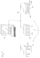
- FIGURE 1 illustrates a bus network 28 interconnecting a personal computer 20 and a plurality of non-computer system devices 21.
- the graphical control system of the present invention employing the object-oriented programming paradigm as described above allows a user to use the personal computer 20 to control the operation of the non-computer system devices 21 via bus network 28.
- the illustrated devices are a two-channel amplifier 22, a tuner 24 and a graphic equalizer 26.
- additional non-computer system devices can be connected to and controlled by personal computer 20 via the bus network 28, if equipped with the necessary interface hardware.
- Non-computer system devices may include video cameras, speakers, television sets, telephones, lamps, etc. Even simple light switches can form non-computer system devices.
- the devices shown in FIGURE 1 are depicted as audio sound system devices, i.e., amplifiers, equalizers, tuners, etc.
- any computer system including but not limited to portable computers, powerbooks, personal device assistants that is equipped with the necessary hardware interface to be connected to bus network 28 or any other coupling medium may be used control the non-computer system devices 21.
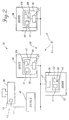
- the personal computer 20 is connected to the network 28 by way of an RS232 interface 42 and a bridge 45.
- Standard personal computers typically include an RS232 card 43 and an RS232 cable 44 for communicating with external devices such as printers.
- RS232 is an interface standard that specifies signal voltage levels, etc.
- RS232 is also a byte-level communication protocol that specifies start bits, stop bits, etc. for sending bytes of data.
- a higher level communication protocol is used on top of the RS232 byte-level communication protocol, i.e., the personal computer 20 includes software defining a point-to-point communication protocol that is used on top of the RS232 byte-level protocol.
- the bridge 45 provides the interface between the RS232 cables 38 and the bus network 28, on which a network communication protocol is used.
- Each non-computer system device 21 includes an interface 35 comprising an I/O board 47 and a processor board 46 which allow the devices to be directly connected to the network 28.
- the I/O board 47 is specifically constructed for use with the bus network configuration and a particular type of transmission medium, whereas the processor board 46 can be used with different communication configurations and transmission media.
- the processor board 46 of interface 35 controls the communication of the devices 21 over the bus network 28.
- the processor board 46 includes a processor 41, an electronically erasable and programmable read-only memory (EEPROM) 58, and a random access memory (RAM) 59.
- EEPROM electronically erasable and programmable read-only memory
- RAM random access memory
- the processor board 46 of interface 35 housed in the device constructs a packet of data representing the relevant information.
- the processor board 46 determines the time at which the bus network 28 is available for sending the packet.
- the processor board 46 sends the packet to the I/O board 47 at the appropriate time, and upon receipt of the packet, the I/O board transmits the packet via the bus network 28 to personal computer 20.
- the processor board 46 of interface 35 processes the packet and performs any appropriate function, possibly including sending a response packet back to the personal computer 20.
- non-computer system devices come equipped with a variety of internal and external feature controls 29a and feature displays 29b that are used to control and monitor the operation of such devices, including but not limited to volume controls, channel selectors, power switches, input and output meters, etc.
- internal controls and displays are represented by phantom lines, while external controls and displays are represented by solid lines).
- the processor boards 46 in the non-computer system devices 21 are further connected to these controls and displays to either control the devices directly or to control the devices in conjunction with other processors or controllers within the devices based upon packets received over the bus network 28.
- the bus network 28 shown in FIGURES 1 and 2 can be formed of various coupling media such as glass or plastic fiber optic cables, coaxial cables, twisted wire pair cables, ribbon cables, etc. In the professional audio industry it is generally preferable to use fiber optic cables, as fiber optic cables are highly immune to electromagnetic interference and are capable of carrying signals over long distances without significant attenuation. As described herein, the bus network 28 represents fiber optic cables. Accordingly, the I/O board 47 of interface 35 shown in FIGURE 2 is constructed for use with fiber optic cables.
- the network communication protocol used to communicate over the bus network 28 is of the type disclosed in commonly assigned U.S. Patent No. 5,245,604, entitled “Communication System,” the disclosure and drawings of which are specifically incorporated herein by reference.
- the network communication protocol described by U.S. Patent No. 5,245,604 is referred to herein as the MediaLink protocol.
- the advantage of the MediaLink protocol is that it provides an upper limit on the amount of time it takes to communicate over the bus network 28. This is important in real-time environments such as a musical performance stage, where unpredictable delay would result in unacceptable distortion.
- the MediaLink protocol includes a network resource sharing and management algorithm such that only one device communicates over the bus network 28 at any one given time and such that each device has sufficient access to the bus network 28. While the MediaLink protocol and the bus network are presently preferred, it is to be understood that other network protocols and networks other than the type shown in FIGURES 1 and 2 may be used in actual embodiments of the invention, if desired.
- a non-computer system device 21 may be connected to personal computer 20 in a point-to-point configuration by way of a cable so that a bridge 45 is unnecessary.
- the device would include the interface 35 having processor board 46 and I/O board 47.
- the I/O board 47 would be specifically constructed for use with the point-to-point configuration and a particular type of transmission medium. Network and access management would obviously be unnecessary since the personal computer and the device are interconnected in a point-to-point configuration.
- the device is connected to the personal computer 20 by a RS232 cable.
- the coupling medium could also include a radio frequency coupling medium or other coupling media.
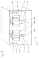
- a non-computer system device 21 connected to the personal computer 20 via the network 28 FIGURE 1) is shown in more detail in FIGURE 3.
- the chosen non-computer system device 21 is the two-channel amplifier 22, which has a control and display panel 48 that contains a number of feature controls 29a, including a first fader 49, a second fader 50, a first power switch 51, a second power switch 52; and feature displays 29b, including a first input meter 53, a first output meter 54, a second input meter 55, and a second output meter 56.
- One of the faders, power switches and input and output meters is associated with each of the channels.
- the feature controls and displays shown in FIGURE 3 should be construed as exemplary and not limiting.
- Other types of amplifiers could include various controls and displays (such as mute controls, fuse temperature gauges, etc.) other than or in addition to those shown in FIGURE 3.
- devices other than amplifiers include other types of controls and displays, depending upon the nature of each device.
- the amplifier 22 shown in FIGURE 3 is equipped with the hardware described above necessary to connect the amplifier 22 to the personal computer 20 via the network 28 so that data packets may be sent between the amplifier 22 and the personal computer 20. More specifically, the amplifier 22 is equipped with a processor board 46 and an I/O board 47. With respect to the processor board 46, the processor 41 preferably includes read-only memory (ROM) that stores program code for controlling the communication of the device with the personal computer 20 and with other devices.
- the EEPROM 58 is used by the processor 41 for controlling the functionality of the amplifier 22 and stores a portion of the visual network operating system.
- the RAM 59 is used by the processor 41 during operation to temporarily store some program code and data, including a class database containing instances of each class employed by the portion of the visual network operating system stored in the EEPROM.
- Each of the feature controls 29a and feature displays 29b of the amplifier 22 governs a certain feature or aspect associated with the amplifier and can be represented by a numerical value.
- the first fader 49 controls the volume produced by one of the channels of the amplifier 22.
- the value represented by the setting of the first fader is a number of decibels being output by the amplifier 22.
- the first power switch 51 is another example.
- the first power switch controls the application of power to the first channel of amplifier 22. When power is being supplied, the state of the power switch can be represented by the value "1". When power is not being supplied, the state of the power switch can be represented by the value "0".
- each feature display 29b such as first and second input meters 53 and 55
- the reading of each feature display 29b can be represented by a numerical value as well.
- Displays normally represent constantly fluctuating values.
- first input meter 53 monitors the level of power being input into the first channel, designated Channel 1, of the amplifier. Since the power level constantly fluctuates, the numerical value representing the power level and hence, the second input meter reading, constantly fluctuate as well.
- each control and display that governs an aspect of any device controllable by a graphical control system formed in accordance with the present invention can be represented by a numerical value.
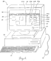
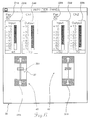
- the personal computer 20 included in FIGURES 1 and 2 is shown in more detail in FIGURE 4.
- the personal computer 20 includes a display or monitor 30, a keyboard 31, a mouse 32, and a main unit 33.
- the monitor 30 includes a screen 34 on which various elements of a graphical control system formed in accordance with this invention are displayed.
- the displayed elements include windows 36 and 38, and graphics cursor 37.
- One of the illustrated windows 36 is named “Network Inventory” and the other illustrated window 38 is named "Amplifier Panel.”
- the Network Inventory window 36 contains three icons 39, each of which represents one of the non-computer devices 21 connected to the bus network 28.
- the Amplifier Panel window 38 represents the control panel 48 of the amplifier 22 and includes a plurality of visual device controls (VDCs) 40, each of which graphically represent a feature control 29a or feature display 29b used to control the amplifier 22.
- VDCs visual device controls
- FIGURE 4 the same reference numbers plus the letter "a" are used in FIGURE 4 to refer to the visual device controls (VDCs) as were used to refer to the feature controls and displays shown in FIGURE 3.
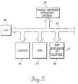
- FIGURE 5 For purposes of explaining the operation of the graphical control system of the invention, several of the key components of the personal computer 20 are illustrated in FIGURE 5. It will be apparent to those of ordinary skill in the art that personal computer 20 includes many more components than those shown in FIGURE 5. Such other components are not described because they are conventional, and an understanding of them is not necessary to an understanding of the present invention.
- FIGURE 5 shows a CPU 60 coupled by a bus 62 to a read-only memory (ROM) 67 and a random access memory (RAM) 68.
- the CPU responds to program instructions stored in the ROM 67 and temporarily in the RAM 68.
- the computer 20 also includes a permanent storage device 66, such as a hard disk drive or a floppy disk drive, that is connected to the CPU by the bus 62.
- the CPU 60 is controlled by a portion of the visual network operating system 78 functionally shown as coupled to the bus 62, but actually stored in a suitable one of the memories.
- a class database 65 containing instances of each class employed by the visual network operating system 78 is stored in the RAM 68.
- the visual network operating system 78 provides the CPU with various conventional platform operating services, including but not limited to network polling, task scheduling, loading and saving data and objects, massive object and data manipulation, object creation and disposal, and database traversal.
- the graphical control system produces the Amplifier Panel window 38 on the screen 34 of the personal computer 20.
- FIGURE 6 shows the Amplifier Panel window in much greater detail.
- the Amplifier Panel window 38 is a predefined graphical control display of the control panel 48 of the amplifier 22 shown in FIGURE 3. Consequently, the Amplifier Panel window 38 contains a VDC 40 for each feature control 29a or feature display 29b of the amplifier 22.
- each VDC 40 graphically represents a control or display of the amplifier, each VDC 40 visually represents and controls the value actually represented and governed by its control 29a or display 29b counterpart That is, the VDCs 40 may either exactly replicate external and internal feature controls 29a and displays 29b on screen 34 that a user would find on the amplifier 22, or the VDCs may functionally represent such controls and displays.
- a rotary knob on the amplifier 22 may be functionally represented by a VDC in the form of a slide display; or a VDC in the form of a linear scale or number display may be used to functionally represent a dial display.
- the graphical control system of the present invention produces a predefined graphical control display that represents the control panel of the device, wherein the graphical control display contains a VDC 40 for each control 29a and display 29b of the device.
- each VDC 40 visually represents and controls the value actually represented and governed by its control or display counterpart.
- the VDC 49a that graphically represents the first fader 49 of the amplifier 22, controls the volume the amplifier by producing a value represented by the setting of the VDC 49a that is the number of decibels being output by the amplifier.
- the VDC 51a that graphically represents the first power switch 51 of the amplifier 22 controls a binary signal that represents the value "1" when power is being supplied, and the value "0" when power is not being supplied.
- the VDC 53a that graphically represents the first input meter 53 of the amplifier represents and monitors the value associated with the power level being input to the device at any given instant in time.
- VDCs 40 represent the controls 29a and displays 29b of a device 21, it will be understood that the graphical control system of the present invention eliminates the need for external, manually operable controls and displays.
- the devices 21 on the network 28 are fully controlled by the personal computer 20 and do not include any external, manually operable feature controls and feature displays whatsoever.
- the elimination of external feature controls and feature displays reduces the cost and difficulty of manufacturing non-computer system devices. While the invention can be implemented in a way designed to eliminate the need for non-computer system devices to have external controls and displays, it is to be understood that in some embodiments of the invention it may be desirable to include external controls and displays.
- VDCs 49a, 50a and 53a graphically represent the first fader 49, the second fader 50 and the first input meter 53 of the amplifier 22 shown in FIGURE 3, respectively.
- the second input meter 55 is graphically represented by another VDC 55a
- the first and second output meters 54 and 56 are graphically represented by still other VDCs 54a and 56a, respectively.
- still other VDCs 51a and 52a represent the first and second power switches 51 and 52, respectively.
- the VDCs 40 differ from the icons 39 shown in FIGURE 4 in that each icon is a static graphical representation of an entire device itself. Merely selecting an icon using the mouse does not control the feature controls 29a and displays 29b of the device. In contrast, a VDC 40 is a dynamic graphical replica or representation of the feature controls 29a and feature displays 29b of a device 21, having the same properties and characteristics of its control or display counterpart. Therefore, in order to initiate execution of one of the controls or displays of the amplifier 22 shown in FIGURE 3 using the graphical control system of the present invention, the user manipulates cursor 37 using the mouse 32, such that the cursor is positioned over the desired control VDC 40 in the Amplifier Panel window 36.
- the VDC 49c represents first fader 49 and is used to control the volume of Channel 1 of the amplifier 22.
- the value represented by the setting of this VDC 49a is the volume being output by the amplifier, which may be displayed in decibels.
- the user manipulates the cursor 37 using the mouse 32, such that the cursor is positioned over a visual control element or device "knob" 301 that forms part of the first fader VDC 49a.
- the first fader VDC 49a is graphically manipulated and reset, resulting in a change to the value represented by the first fader VDC 49a.
- This change in value is then communicated by the graphical control system of the present invention to the amplifier 22, where the graphical control system further causes the amplifier interface 35 to adjust the Channel 1 volume controlled by first fader 49 so that it corresponds to the change in value.
- the first fader 49 also may be effectuated manually, electrically or by control of another personal computer connected to the bus network 28. For example, if the Channel 1 volume of the amplifier 22 is increased by manually operating the first fader 49, a change in the value represented by the first fader results.
- the graphical control system communicates the change in value to the personal computer 20 so that the visual device control element or knob 301 of the first fader VDC 49a is regenerated in a manner that visually corresponds to the change in value.
- VDCs 40 shown in FIGURE 6 represent feature displays that are constantly being updated.
- the first input meter 53 monitors the power level input into Channel 1 of the amplifier 22 at any given instant.
- the value representing power level that is displayed by the first input meter 53 is constantly fluctuating.
- the graphical control system constantly communicates this change in value to the personal computer 20.
- the platform operating services provided by the VNOS 78 constantly poll the bus network 78 for such changes in value.
- the first input meter VDC 53a is regenerated, its visual device control element or display "value" changes in accordance with the actual fluctuation of the first input meter 53.
- a user can monitor the first input meter 53 of the amplifier 22 from the screen 34.
- the element of the graphical control system that controls the personal computer system 20 and the device interface 35 such that the VDCs 40 replicate and control the feature controls 29a and displays 29b is the visual network operating device 78, which is described next.
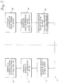
- FIGURE 7 is a flow chart illustrating the control and monitoring functions performed by the visual operating system (VNOS) 78 of the present invention and the order in which these functions are performed.
- VNOS 78 is a distributed operating system that is partially stored in the personal computer 20 and partially stored in the interfaces 35 of the devices 21. The major portion is stored in the personal computer.
- Blocks 80, 81 and 82 represent the functions of VNOS that control the operation of the personal computer 20 and blocks 83, 84 and 85 represent the functions of VNOS that control the interface 35 of a device 21.
- VNOS generates a graphical control display upon the screen 34 of the personal computer 20 that contains a number of VDCs 40.
- each VDC graphically represents a corresponding feature control 29a or feature display 29b of one of the devices 21 to be controlled (FIGURE 1).
- each VDC represents a particular value associated with a corresponding control 29a or display 29b.
- VNOS interprets the value which is then stored in RAM 68 of the personal computer 20.
- VNOS may further manipulate and change the value before storing it.
- VNOS communicates the change in the value associated with the feature control or display to the related device 21 via the bus network 28.
- VNOS receives the change in value associated with the feature control 29a or display 29b.
- VNOS interprets and stores the change in value in the RAM 59 located in the interface 35. Again, in some embodiments VNOS may further manipulate and change the value before storing it.
- VNOS causes the interface 35 to adjust the corresponding control or display in accordance with the change in value stored in the interface RAM.
- VNOS 78 of the graphical control system of the present invention is designed, in part, for use in the forward direction beginning at block 80 and preceding to block 85
- the device 21 may be manually operated by a control 29a located on the device or by another computer.
- a control 29a or display 29b may be automatically and electrically adjusted by a command generated internally, as is the case with meters and temperature gauges that monitor constantly fluctuating values.
- the order in which the VNOS functions are performed in FIGURE 7 is reversed so that communication begins at block 85 and proceeds to block 80.
- a change in value resulting from an adjustment of a feature control or display at the device 21 is sent from the device to the other devices and to the personal computer.
- the VDC representing the control or display on the screen 34 of the personal computer is regenerated in accordance with the change in value.
- VNOS 78 uses an object-oriented programming paradigm to represent non-computer system devices 21.
- object-oriented programming paradigms are abstract generic descriptions of objects and their behaviors.
- a class defines a certain category or grouping of methods and data within a object.
- Methods provide the "intelligence" of a class and comprise procedures or codes that operate upon the data.
- Methods as applied to data define the behavior of an object.
- This concentration of intelligence in the methods of object classes is essential in object-oriented systems. It permits large-scale maintenance efforts, since the methods or intelligence of objects is inherited from their class. So, effecting a change once in the methods of a class will automatically effect changes in the methods of all the objects of that class and its subclasses.
- an object 90 can be modeled by a doughnut, with data 92 being located in the center of the doughnut.
- the data 92 represents various attributes of the object 90 including but not limited to addresses in memory for the instances of the object, a database containing more objects, and pointers to other objects.
- Around the outer part of the doughnut are two regions denoted generic methods 96 and 98, and another region denoted class-specific methods 94, which are employed by the graphical control system of the present invention to interact with the data 92.
- Another fundamental aspect of object-oriented programming is that objects are interoperable.
- the generic methods 96 and 98, and class-specific methods 94 that interact with the data 92 totally surround the data and, in a sense, encapsulate the data. Only the methods in the outer part of the doughnut are allowed to know anything about the data.
- the methods isolate the encapsulated data from other parts of the system making the object interoperable with other objects regardless of the data contained by those objects.
- the user is capable of modifying the system as new devices appear or disappear on the network, by merely changing the data, since an object is interoperable and need only be concerned about how it represents the data for which it is responsible.
- Generic methods 96 and 98 around the outer part of the doughnut are generic methods present in all objects of a class.
- Generic methods 96 are generally those used to translate the data 92 into a linear, textual representation so that the data can be directed to and from a text file in storage 66 of the personal computer 20 by the platform operating services of VNOS 78.
- Generic methods 96 are employed when the user requests a full state save or restoration of all objects upon shut-down or power-up of the personal computer.
- Generic methods 96 are also referred to as "interpret and describe" methods.
- Generic methods 98 provide for communication between objects including methods for generating pointers to other objects and methods for sending messages to other objects.
- class-specific methods 94 are unique for a particular class.
- the class-specific methods 94 usually provide the logic that implements special behaviors of the object 90 that are unique to the particular class.
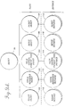
- FIGURE 9A shows the object-oriented programming paradigm from a class hierarchy perspective as employed by the portion of VNOS 78 stored in the personal computer.
- objects are categorized into classes, where a class defines a category of methods and data within its objects. Methods as applied to data define the behavior of an object. An instance is a specific object with the behaviors defined by its class.
- the object-oriented programming paradigm employed by the portion of VNOS 78 stored in the personal computer 20 primarily employs five different objects -- a window object 100, a visual reference object 102, a value control element (VCE) object 104, a device object 106 and a packet object 108. Each object is shown as a class beneath the class "object" 90.
- VCE value control element
- window objects 100 contain the data and methods necessary for displaying a window on a computer screen 34; visual reference objects 102 contain the methods and data necessary for generating an icon 39 or VDC 40 of a window object; value control element (VCE) objects 104 contain the value represented by a VDC and the methods for manipulating that value; device objects 106 contain the methods and data for communicating with a particular type of non-computer system device 21 and for managing a graphical control display of that device; and packet objects 108 contain the methods and data for communicating data between a device 21 and the computer 20 via the bus network 28.
- VCE value control element
- the window, visual reference, VCE, device and packet objects may be subdivided into further subclasses.
- device object 106 may be divided into subclasses of amplifiers, equalizers, CD players, etc, Each of these subclasses may then be subdivided again.
- the subclass of amplifiers may be divided into subclasses of amplifiers wherein each subclass comprises amplifiers produced by a particular manufacturer.
- FIGURE 9A also illustrates the relationship between object classes and instances (i.e., specific objects) in the object-oriented programming paradigm. As previously described, each object is shown as a class beneath the class "object" Further, each class can generate one or more instances Amplifier Panel window 38 in FIGURE 6 is an example of a window instance 110 of window object 100, wherein window object 100 is shown as a class beneath the class "object.”
- a VDC 40 contained in a window instance 110 such as the first fader VDC 49a in Amplifier Panel window 38 shown in FIGURE 6 is represented by a visual reference instance 112 of visual reference object 102.
- the visual reference object 102 is also shown as a class beneath the class "object.”
- Each VDC in a window instance 110 is represented by its own visual reference instance.
- Visual reference instance 112 may have associated with it a value control element (VCE) instance 114. If so, a VCE instance 114 is generated when a VDC 40 is displayed in the window instance 110.
- the VCE instance 114 contains the particular value or change in value represented by the VDC.
- the VCE instance 114 will contain the value 6. If the first fader VDC 49a is reset to 8 decibels, then the VCE instance 114 will be changed to the value 8.
- Each VCE instance 114 is associated with a device instance 116.
- An example of a device instance 116 is the amplifier 22.
- a device instance will exist for each device 21 on the network.
- each device instance 116 may be associated with a packet instance 118.
- Each packet instance 118 represents either an incoming or outgoing packet that is communicated between a device 21 and the personal computer 20 via the bus network 28.
- object 90 contains data 92, generic methods 96 and 98, and class-specific methods 94.
- object 90 contains data 92, generic methods 96 and 98, and class-specific methods 94.
- Each of the five objects employed by VNOS 78 and shown as a class beneath the class "object" 90 inherits data 92, generic methods 96 and 98, and class-specific methods 94, while adding new data and methods.
- FIGURE 9B illustrates the new and inherited methods and data contained by each of the five objects depicted in FIGURE 9A. Since the methods and data within each of the five objects comprises methods and data inherited from class "object" 90 plus new methods and data, the reference numbers used in FIGURE 9B to identify the methods and data within each of the five objects mirror those used to identify the methods and data of object 90.
- each window object 100 provides the data and methods necessary for displaying a window on screen 34.
- the data 502 contained by a window object 100 comprises a database of visual reference objects 102 and list of pointers to related visual reference objects, VCE objects, device objects, and other window objects.
- the generic methods 506 and 508 contained in a window object 100 will comprise inherited generic methods 96 and 98 from the class "object" 90 and new methods. Consequently, the generic methods 506 translate window object data 502 into a linear, textual representation that is directed to a text file located in the storage 66 of the personal computer 20.
- class-specific methods 504 contained in a window object 100 provide the graphical appearance of a window as defined by that computer's particular windowing environment, such as the Apple Mac OS or Microsoft Windows.
- class-specific methods 504 provide for the organization of the icons 39 and VDCs 40 within the window object 100.
- the generic methods 508 of a window object provide communication between the remaining four classes of objects.
- a visual reference object 102 The purpose of a visual reference object 102 is to generate visible screen entities such as icons 39 or VDCs 40 in the window objects 100.
- the class-specific methods 524 of a visual reference object 102 generate the graphical general appearance of an icon 39 or a VDC 40.
- the class-specific methods 524 of a visual reference object 102 may also be used to change a style or functional representation of a VDC 40.
- class-specific methods 524 provided by a user may cause a VDC originally in the form of a dial display to be regenerated into a linear scale or number display. Further, class-specific methods 524 provided by the user can change the type, color, shape, size, orientation or operation thresholds of a VDC 40.
- class-specific methods 524 provided by a user may cause a VDC originally in the form of a dial display to be regenerated into a linear scale or number display. Further, class-specific methods 524 provided by the user can change the type, color, shape, size, orientation or operation thresholds of a VDC 40. A user simply loads or "drops in" code comprising the class-specific methods provided by the manufacturer into a visual reference object 102 in order to generate the custom VDC. Further details concerning the automatic regeneration of a VDC's graphical dimensions is provided below.
- the data 522 of a visual reference object 102 contains a list of pointers to other window objects, VCE objects, device objects, and other visual reference objects having the same origin.
- the generic methods 526 of a visual reference object 102 provide for the translation of the data 522 of the visual reference object, while the generic methods 528 provide communication between the visual reference object 102 and the remaining objects.
- the VCE object 104 serves to interpret, store and perhaps further manipulate the value represented by a VDC 40.
- the data 542 of a VCE object 104 comprises the value represented by the VDC. Consequently, when a VDC is manipulated by the user to cause a change in the displayed value, the VCE object data 542 will change in a corresponding manner.
- the value contained in the VCE object data 542 may undergo further manipulation as provided by the class-specific methods 544 of the VCE object 104.
- the class-specific methods 544 may further change the value by executing a scaling function on the value or converting a numerical value to a textual value.
- a user may load code comprising the class-specific methods into a VCE object 104 using the platform operating services provided by the portion of VNOS 78 stored in the computer 20.
- the VCE object data 542 includes a list of pointers to related window, visual reference, VCE, device and packet objects and generic methods 546 providing for communication between these objects.
- the VCE object itself does not appear on the computer screen 34.
- class-specific methods 544 which would normally control a VCE object's appearance are not present.
- VCE object data 542 comprises a list of pointers to slave and master VCE objects, while the class-specific methods provide logic for manipulating slave and master VCE objects. Further details of this aspect of the invention are provided below.
- a device object 106 contains the methods and data for communicating with a particular type of device 21 and for managing a graphical control display, i.e, a graphical representation of that device in a window.
- the data 562 of a device object 106 contains a database of related VCE objects 104 and list of pointers to the other device objects in the same class.
- Generic methods 566 of a device object 106 provides for data translation, while generic methods 568 of a device object provide for communication between the device object and the four remaining objects.
- Class-specific methods 564 of a device object provide for special window, packet, and VCE object handling and for managing the graphical control display or graphical representation of a device 21 in a window, such as Amplifier Panel window 38 shown in FIGURE 4.
- a packet object 108 contains the methods and data for generically communicating between a device 21 and the computer 20 via the bus network 28.
- the data 582 of a packet object 108 contains a list of pointers to related VCE objects 104 and device objects 106.
- the data 582 of a packet object includes device information to be transmitted over the network in a data packet.
- packet object data 582 contains the value(s) represented by one or more VDCs and stored in one or more VCEs.
- Class-specific methods 584 of a packet object 108 provide for communication between the personal computer 20 and devices 21 via the network 28 over different ports or in conjunction with the MediaLink protocol.
- an instance is a specific object with the behaviors defined by its class.
- An instance inherits all the methods of its class, but has particular data associated with it that is unique. Consequently, each instance 110 through 118 inherits the generic and class-specific methods of its class.
- a window instance 110 inherits the generic methods 506 and 508, and the class-specific methods 504 of the related window object 100.
- a window instance includes generic methods 516 and 518, and class-specific methods 514, plus unique data 512.
- the data and methods of the remaining instances include generic methods, class-specific methods and data.
- the window, visual reference, VCE, device and packet instances are located in the class database 65 stored in the RAM 68 of the personal computer 20.
- the preferred embodiment of the graphical control system of the present invention includes a personal computer 20, an interface 35 for each non-computer system device 21 having at least one feature control 29a or display 29b, a bus network 28 for connecting the computer 20 to the interface(s) 35, and a VNOS 78 based on the object-oriented programming paradigm just described.
- Embodiments of this graphical control system can best be understood by describing the presently preferred embodiment of VNOS 78 and the object-oriented programming paradigm in which it exists. Such a description follows.
- FIGURE 7 it is the window, visual reference, VCE, device and packet instances that carry out the VNOS 78 functions depicted in blocks 80 through 85 and described above.
- the flow of messages between these instances within the object-oriented programming paradigm are more fully described next.
- the pointers linking each instance have been omitted so that only the flow of messages between instances is shown in the accompanying figures.
- the flow of messages follows the paths established by the pointers linking the instances.
- the flow of messages is bi-directional, meaning messages may flow between instances in either direction. An exception exists for messages sent to and from packet instances since packet instances are either incoming from or outgoing to the bus network 28.
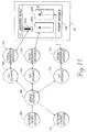
- FIGURE 10 illustrates one actual embodiment of the present invention, in which the graphical control system notifies the user that a device has appeared on the network.
- VNOS 78a generates window instance 120 on the screen 34 of the personal computer 20.
- the window instance 120 shown in FIGURE 10 is the Network Inventory window 38 depicted in FIGURE 4.
- the device interface 35 sends out a special packet announcing the device over the network 40.
- the platform services provided by the portion of VNOS 78 stored in the computer 20 continually poll the network for incoming packets from devices.
- the platform operating services transforms the packet into an incoming packet instance 128, 138 or 148, creates a device instance 126, 136 or 146 representing the new device, and create a visual reference instance 122, 132 or 142.
- the packet instance 128, 138 or 148 sends a message to device instance 126, 136 or 146 notifying it of the device's presence.
- the device instance 126, 136 or 146 sends a message to a visual reference instance 122, 132 or 142.
- the visual reference instance 122, 132 or 142 then provides genetic methods 526 (FIGURE 9B) for generating an icon 400, 402 or 404 representing the device in the window instance 120.
- the appearance of the icon 400, 402 or 404 on the screen 34 notifies the user that device is connected to the bus network 28.
- window instance 120 will contain a plurality of icons 400, 402 and 404, each representing a device 21.
- Related VCE instances 112 are unnecessary because icons do not represent feature controls 29a, and hence, do not have a value associated with such a control.
- the user positions the cursor 37 over the desired icon 400, 402 or 404, and performs a predefined function, such as double clicking a mouse button. For example, if the user selects amplifier 22, represented by icon 400, a window instance 140 of the type shown in FIGURE 11 may appear on the screen 34.
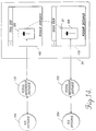
- FIGURE 11 is used to illustrate how the graphical control system of the invention enables a user to control a device via a graphical representation.
- VNOS 78 generates a window instance 140 on the screen 34 based upon performing a predetermined function when a cursor is positioned over a icon.
- the window instance 140 is simplified by showing only a part of the Amplifier Panel window 36 depicted in FIGURES 4 and 6. Specifically, only the Channel 1 input meter VDC 53a and the first and second fader VDCs 49a and 50a are shown.
- the user can graphically manipulate any of the VDCs by using the mouse 32 to guide the cursor 37 and perform some predefined function, such as clicking a mouse button, all in a conventional manner.
- the window instance 140 sends a message to a related visual reference instance 162 notifying it of the change in value.
- the visual reference instance 162 responds in two ways. First, the generic methods 536 of the visual reference instance 162 regenerate the first fader VDC 49a so that it corresponds graphically to the change in value. To the user, this regeneration appears instantaneously. Second, the visual reference instance 162 sends a message to a VCE instance 164 associated with first fader VDC 49a notifying it of the change in value. The VCE instance 164 stores the change in value caused by the user manipulation and sends a message to a device instance 166 that represents the amplifier 22.
- the class-specific methods 544 of the VCE instance 164 associated with the first fader VDC 49a may further manipulate and change the value before sending a message to the device instance 166.
- the user may desire to increase the volume to 20 decibels.
- the user uses the mouse 32 to adjust the movable element of the first fader VDC 49a to a 20-decibel level. If the class-specific methods 544 were predefined to set the maximum allowable decibel level at 15 decibels, the adjustment level (20 decibels) could not be achieved. In this example, the class-specific methods 544 would change the value to be stored in the VCE instance 164 from 20 decibels to 15 decibels.
- VCE instance 164 would then send a message to both the visual reference instance 162 and the device instance 166 notifying them of this change in value. Consequently, visual reference instance 162 would regenerate the first fader VDC 49a so that its movable element would correspond to 15 decibels.
- the class-specific methods 576 of the device instance 166 prepares an outgoing packet instance 178 containing the new value data 592.
- the outgoing packet instance 178 is then transformed into a conventional packet by the platform operating services of VNOS 78 and sent over the network 28 to notity the amplifier 22 of the change in value.
- the amplifier interface 35 Upon receipt, the amplifier interface 35 correspondingly adjusts the volume controlled by first fader 49.
- VNOS 78 at the device interface in adjusting controls, such as the first fader 49, is discussed in more detail below.
- the second fader VDC 50a When the user graphically manipulates the second fader VDC 50a, virtually the same flow of messages results except that the second fader VDC 50a is associated with its own visual reference instance 172 and VCE instance 174.
- the second fader VDC 50a sends a message containing the change in value to the second fader visual reference instance 172, which in turn sends a message to the second fader VCE instance 174.
- the second fader VCE instance 174 sends a message notifying the same device instance 166 of the change in value. Consequently, both the first and second fader VDCs 49a and 50a are linked to the same device instance 166.
- any VDC representing a control 29a or display 29b of the amplifier 22 would be linked through a series of visual reference instances and VCE instances to the same device instance 166 so that any change in value caused by user manipulation of a VDC graphically representing a control or display of the amplifier 22 is funneled to the amplifier 22 via the bus network 28.
- the same procedures apply to any other non-computer system device attached to the bus network.
- VNOS 78 causes the amplifier interface 35 to send a packet containing the change in value to the personal computer 20 via the bus network 28.
- the platform operating services provided by the part of VNOS 78 located at the personal computer 20 transforms the packet into an incoming packet instance 168.
- the incoming packet instance 168 sends a message to device instance 166 of the amplifier that notifies the device instance of the change in value made by the manual adjustment of the first fader 49.
- the generic methods 578 of the device instance 166 then send a message to the VCE instance 164 associated with the first fader VDC 49a.
- the change in value associated with first fader 49 is then stored in the VCE instance 164.
- the VCE instance 164 then sends a message to the visual reference instance 162 notifying it of the change in value.
- the methods of visual reference instance 162 causes the first fader VDC 49 to be regenerated in a manner that corresponds to the change in value effectuated by manually adjusting the first fader 49.
- the second fader 50 of the amplifier 22 is used to change the volume in Channel 2 of the amplifier, virtually the same sequence of events occurs, with one exception.
- the device instance 166 representing the amplifier 22 sends a message to the VCE instance 174 associated with the second fader VDC 50a. Consequently, visual reference instance 172 regenerates the second fader VDC 50a in a way that corresponds to the change in value effectuated by the manual adjustment of the second fader 50.
- VNOS 78 causes the interface 35 of the amplifier 22 to repeatedly send packets to the personal computer 20 via the bus network 28. Each packet contains the change in value associated with the first input meter 53 at a particular instant.
- the platform operating services provided by the portion of VNOS 78 stored in the computer constantly poll the bus network 28 for incoming packets. Thus, the platform operating services transform received packets in rapid succession.
- the device instance 166 of the amplifier 22 sends a message to a VCE instance 154 associated with the first input meter VDC 53a.
- the VCE instance 154 stores the change in value associated with the first input meter 53 and sends a message to a visual reference instance 152. Consequently, visual reference instance 152 regenerates the first input meter VDC 53a.
- the visual reference instance 152 is constantly receiving a message notifying it of a change in value because the power level being input into the amplifier 22 is constantly fluctuating. Therefore, the visual reference instance 152 is constantly regenerating the first input meter VDC 53a so that the first input meter VDC 53a graphically depicts the changing power level being input into the amplifier 22.
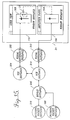
- FIGURE 12 illustrates the flow of messages between object instances when the graphical control system of the present invention enables the user to create a cloned VDC.
- the same Amplifier Panel window instance 140 that appeared on screen 34 in FIGURE 11 now appears on screen 34 in FIGURE 12.
- the user has created another window instance 150 entitled "User View.”
- a user makes a cloned VDC by dragging the desired VDC from window instance 140 and dropping the dragged VDC into the User View window instance 150 by manipulating a mouse 32 in a conventional manner. More specifically, a user moves the mouse until the cursor 37 is positioned over the VDC, such as the second fader VDC 50a, to be dragged and dropped.
- a mouse key is clicked (i.e., depressed).
- the mouse with the depressed key is then manipulated to move the cursor to a desired location in the User View window instance 150, as shown by the dashed line in FIGURE 12.
- the mouse key is released.
- the end result is a second fader VDC clone 50aa located in the User View window instance 150.
- the platform operating services provided by VNOS 78 retrieve a visual reference instance 182 from the class database 65 and link the visual reference 182 to a VCE instance 174 associated with the second fader VDC clone 50aa.
- the first fader VDC clone 50aa is an equivalent or clone of the second fader VDC 50a.
- the user may use the second fader VDC clone 50aa to control the amplifier 22 instead of the second fader VDC 50a in the same way as the second fader VDC 50a can be used to control the amplifier.
- the user manipulates the second fader VDC clone 50aa, the value visually represented by the second fader VDC 50aa is changed.
- the User View window instance 150 sends a message to the visual reference instance 182.
- the class-specific methods 534 of the related visual reference instance 182 instantaneously respond and regenerate the second fader VDC clone 50aa so that it graphically corresponds to the change in value.
- the class-specific methods 534 also support other graphical alterations made to the second fader VDC clone, such as color changes, size, orientation, operation thresholds, and even the style of the VDC.
- these graphical alterations do not affect the value visually represented by the second fader VDC, nor do they affect the second fader VDC itself, as it appears to the user.
- the visual reference instance 182 regenerates the second fader VDC clone 50aa
- the visual reference instance 182 also sends a message to the VCE instance 174 associated with both the second fader VDC 50a and the second fader VDC clone 50aa.
- the VCE instance 174 stores the change value. Since the VCE instance 174 is also associated with the second fader VDC 50a, the VCE instance 174 sends a message to visual reference instance 172 associated with the second fader VDC, which regenerates the second fader VDC 50a in a manner that reflects the change in value. To the user it appears that both the second fader VDC clone 50aa and the second fader VDC 50a are simultaneously regenerated on the computer screen 34.
- the VCE instance 174 sends a message to the device instance 166 associated with the amplifier 22 notifying it of the change in value effected by the user manipulation of the second fader VDC clone 50aa.
- the general methods 576 of the device instance 166 then prepare a outgoing packet instance 178 containing data 592 comprising the change in value.
- the outgoing packet instance 178 is then transformed into a conventional packet by the platform operating services provided by VNOS 78 and sent to the amplifier 22 over the network 28.
- the amplifier interface 35 adjusts the volume controlled by the second fader 50 to correspond to the change in value.
- the behavior of second fader 50 can be controlled by the first fader VDC 50a, the behavior of second fader 50 can be controlled by the second fader VDC clone 50aa.
- any VDC 40 in any window instance can be cloned in another window instance.
- a user could create three cloned VDCs in the User View window instance 150 shown in FIGURE 12 in the manner described above, one for each of the non-computer system devices (the amplifier 22, the tuner 24 and the equalizer 26) connected to the network. Or only some of the VDCs can be cloned into the User View window. In this way a user can create his or her own unique graphical control display comprising VDCs associated with numerous devices.
- first fader 49 or the second fader 50 of the amplifier 22 are manually or electrically operated, or operated by another computer, the flow of messages illustrated in FIGURE 12 is reversed. More specifically, if first fader 49 of the amplifier 22 is manually operated, VNOS 78 causes the amplifier interface 35 to send a packet to the computer 20 via the bus network 28. When the packet is received, the packet is transformed by the platform operating services provided by VNOS 78 into a incoming packet instance 168. The incoming packet instance 168 sends a message to the device instance 166 notifying it that a change has occurred in the value associated with the first fader 49. Consequently, device instance 166 sends a message to the first fader VCE instance 164.
- the first fader VCE instance 164 stores the change in value and sends a message to the first fader visual reference instance 162.
- the first fader visual reference instance 162 then regenerates the first fader VDC 49a such that it visually corresponds to the change in value effectuated by the manual operation of the first fader 49.
- the same sequence of events occurs except that the device instance 166 representing the amplifier 22 sends a message to the VCE instance 174 associated with both the second fader VDC 50a and the second fader VDC clone 50aa.
- the VCE instance 174 sends a message to both the second fader VDC visual reference instance 172 and to the second fader VDC clone visual reference instance 182 notifying them of the change in value.
- the second fader VDC visual reference instance 172 causes the second fader VDC 50a to be regenerated in the Amplifier Panel window instance 140, while the second fader VDC clone visual reference instance 182 causes the second fader VDC clone 50aa to be regenerated VDC 304 in the User View window instance 150.
- the second fader VDC and the second fader VDC clone are simultaneously being regenerated in a way that corresponds to the change in value effectuated by the manual or electrical change made to the second fader 50 of the amplifier.
- FIGURE 13 includes a User View window instance 150 that includes the second fader VDC clone 50aa of the amplifier 22. While for purposes of clarity in illustration, the accompanying VCE, device and packet instances have been omitted from FIGURE 13, it will be appreciated that second fader VDC clone 50aa remains associated with those instances from FIGURE 13, which are depicted in FIGURE 12, through the associated visual reference instance 182. As will be better understood from the following description, it is immaterial for purposes of this aspect of the invention whether the depicted VDC clone 50 is an original or a cloned VDC.
- the second fader VDC clone 50aa shown in FIGURE 13 is a graphical representation of second fader 50 of the amplifier 22.
- the second fader VDC clone 50a appears as a rectangle having a height greater than its width that is operated vertically by moving a graphical knob 305 upwardly toward a maximum (MAX) value or downwardly toward a minimum (MIN) value.
- MAX maximum
- MIN minimum
- the knob is "moved” by appropriately manipulating a mouse or other cursor control device. Movement of the graphical knob changes the value represented by the second fader VDC clone 50aa and, in turn, causes the second fader VDC clone 50aa to be regenerated with the change in value depicted.
- FIGURE 13 also includes three other second fader VDC clones 50'aa, 50''aa, and 50'''aa having different height and width dimensions but otherwise having the same graphics as the second fader VDC clone 50aa.
- the height of the first other second fader VDC clone 50'aa is less and the width greater than the original second fader VDC clone 50aa.
- the height of the second other second fader VDC clone 50''aa is less and the width greater than the first other second fader VDC clone 50'aa.
- the height of the third other second fader VDC clone 50'''aa is less and the width greater than the second other second fader VDC clone 50''aa. Further, the orientation of the second fader clones is different.
- the knob 305 of the original and first other second fader VDC clones 50aa and 50'aa are positioned for vertical movement, whereas the knob 305 of the second and third other second fader DC clones are positioned for horizontal movement. How VNOS changes a VDC is the manner shown in FIGURE 13 is described next.
- Generic methods 566 of the visual reference instance 182 associated with the second fader VDC clone 50aa allow a user to use a mouse 32 or other cursor control device to simultaneously decrease the height of a VDC while increasing the width of the VDC. This is accomplished, for example, by using the mouse to place the cursor 37 over one vertical edge of the second fader VDC clone 50aa, depressing a button located on the mouse to "click" on the edge and dragging the edge outwardly by moving the mouse in the appropriate direction. As the width of the VDC increases, the height automatically decreases. Continuing this action transforms the VDC from a VDC having a height greater than its width to a VDC having a width greater than its height.
- the related window instance 150 sends a message to the visual reference instance 182 associated with the second fader VDC clone.
- the class-specific methods 524 of the visual reference instance 182 cause the second fader VDC clone to be automatically regenerated in a form designed for horizontal as opposed to vertical operation.
- the orientation of the second fader VDC clone is rotated by 90°.
- the second and third other second fader VDC clones 50''aa and 50'''aa still graphically represent the second fader 50 of the amplifier 22, they are operated by the graphical knob 305 of the VDC horizontally rather than vertically.
- the automatic reorientation of the second fader VDC clone does not result in a change in value nor does it result in a change of the MAX and MIN values. Consequently, no messages are sent to the other VCE, device and packet instances (FIGURE 12).
- the second fader VDC clone may be returned to its original form having its original orientation and dimensions by reversing the foregoing procedure, if desired. It will also be appreciated that any other VDC 40 may be automatically resized and, if desired, reoriented in a similar manner.
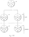
- FIGURES 14, 15 and 16 illustrate how a master VDC is created and used to control a plurality of noncomputer system devices 21.
- VNOS 78 is enabled to generate a window instance 160 entitled “Toolbox” which contains one or more "template” VDCs 306.
- a VDC is considered a "template” because it is not actually associated with any particular device 21.
- a template VDC graphically replicates a feature control or display of a hypothetical device. Because no device exists, only the template VDC 306 and an associated visual reference instance 192 are needed.
- a template VCE instance 194 contains a null value.
- a master VDC is created by a user first cloning the desired template VDC 306 in a User View window instance 170, using a mouse or other cursor control device to manipulate the cursor 37 in the manner previously described.
- the related visual reference instance 192 and template VCE instance 194 are replicated as well.
- new visual reference and VCE instances are created.
- the master VDC 308, the master visual reference instance 202, and the master VCE instance 204 respectively.
- Tool Box window instance 160 may contain a number of "template” VDCs, each of which can be cloned in one or more User View window instances in the manner described above. It will also be appreciated that a template VDC may be "dropped" upon another VDC 40 using the mouse and that the VDC 40 will regenerate itself accordingly.
- FIGURE 15 two window instances are shown on screen 34 of the personal computer 20, the User View window instance 170 shown in FIGURE 14 and an Amplifier Panel window instance 180.
- the User View window instance 170 contains the master VDC 308.
- FIGURE 15 also includes the master reference instance 202 and the master VCE instance 204.
- the Amplifier Panel window instance 180 contains a VDC 310 that graphically represents a control 29a, such as a fader, of a amplifier.
- the user using a mouse or other cursor control device to manipulate the cursor 37 drags the amplifier control VDC 310 from the Amplifier Panel window instance 180 into the User View window instance 170 in the manner previously described.
- the amplifier control VDC 310 is moved until it is positioned atop the master VDC where it is trapped by the user releasing a depressed key of the mouse or other cursor control device.
- an object-to-object interaction (as shown by the dotted line and phantom VDC) occurs.
- the object-to-object interaction establishes a master-slave relationship between the amplifier control VDC 310 and the master VDC 308.
- the object-to-object interaction causes the User View window instance 170 to send a message to the master visual reference instance 202, which in turn sends a message to the master VCE instance 204.
- the class-specific methods 554 of the master VCE instance 204 establish a link to a VCE instance 214 associated with the amplifier control VDC 310 by generating a pointer that points from the master VCE instance 204 to the amplifier control VCE instance 214, and a pointer from the amplifier control VCE instance 214 to the master VCE instance 204 (as noted earlier, pointers have been omitted in FIGURE 15, for purposes of clarity in illustration).
- the class-specific methods 554 of the master VCE instance 204 have the ability to send control messages to the amplifier control VCE instance 214 and thereby control the behavior of amplifier control VCE instance 214.
- the master VCE instance 204 becomes a master of the amplifier control VCE instance, which, in turn, becomes a "slave" VCE instance.
- the pointer to the amplifier control (slave) VCE instance 214 is added to a list of slave pointers included in the data 552 of the master VCE instance 204; and the pointer to the master VCE instance 204 is added to a list of master pointers included in the data of the amplifier control (slave) VCE instance 214.
- a further consequence of the master-slave relationship between the master VCE instance 204 and the amplifier control (slave) VCE instance 214 is that master VDC 308 controls the amplifier control, VDC 310 which, in turn, becomes a "slave" VDC.
- the master VDC 308 since the master VDC 308 is associated with the master VCE instance 204, and the master VCE instance 204 governs the behavior of the amplifier control (slave) VCE instance 214, the master VDC 308 governs the amplifier control (slave) VDC 310.
- the user may use the master VDC 308 located in the User View window instance 170 to control the feature (i.e., the amplifier control) depicted by the amplifier control (slave) VDC 310 in window instance 180. More specifically, when the user manipulates the master VDC 308, User View window instance 170 sends a message to the master visual reference instance 202. The master visual reference instance 202 simultaneously regenerates the master VDC 308 to correspond to the change in value and sends a message to the master VCE instance 204. The master VCE instance 204 stores the change in value and sends a control message to the amplifier control (slave) VCE instance 214. Prior to the message being sent, the class-specific methods 544 of the master VCE instance 204 may further manipulate the value.
- the master VDC 308 located in the User View window instance 170 to control the feature (i.e., the amplifier control) depicted by the amplifier control (slave) VDC 310 in window instance 180. More specifically, when the user manipulates the master VDC 308, User View window
- the amplifier control VCE instance 214 stores the change in value contained in the message received from the master VCE instance 204 and sends messages to the device instance 216 and the visual reference instance 212 notifying both of the change in value.
- the device instance 216 sends a message to outgoing the packet instance 218.
- the outgoing packet instance 218 transforms this message into a conventional packet and sends the packet to the device being controlled (i.e., the amplifier) via the bus network 28.
- device interface 35 adjusts the control of the device 24 to correspond to the change in value effectuated by the master VDC 310.
- the amplifier control visual reference instance 212 causes the amplifier control (slave) VDC 310 to be regenerated in a way that shows the change in value effectuated by the master VDC 308.
- the amplifier control (slave) VDC 310 graphically corresponds to the master VDC 308.
- the master VDC 308 can also be used to control a plurality of slave VDCs, as long as the slave VDCs are of the same type (e.g., the slave VDCs must graphically represent the same type of control or display).
- the master VDC 308 can simultaneously control a plurality of the same type of controls from the same device or a plurality of the same type of controls from different devices.
- FIGURE 16 includes all of the elements of FIGURE 15 plus a second Amplifier Panel window instance 190.
- the second Amplifier Panel window instance 190 contains an amplifier control VDC 312 that graphically replicates the master VDC 308 and the first amplifier control VDC 310.
- the amplifier control VDC 312 is shown as a replica of the master VDC 308 in FIGURE 16 for ease of description, graphical replication of VDCs is not required. Rather, only functional identity is required. For example, a rotary control knob is functionally identical to a linear sliding knob, but graphically different
- a user drags the second amplifier control VDC 312 from the second Amplifier Panel window instance 190 into the User View window instance 170 and drops it on the master VDC 308, creating another object-to-object interaction (as shown by the dotted line and phantom VDC in FIGURE 16).
- This object-to-object interaction results in the creation of another master-slave relationship between the second amplifier control VDC 312 and the master VDC 308.
- the VCE instance 224 associated with second amplifier control VDC 312 becomes a "slave" VCE instance 224 to the master VCE instance 204; and the second amplifier control VDC 312 becomes a "slave” to the master VDC 308. Consequently, the graphical manipulation of the master VDC 308 will result in an adjustment of the amplifier control of two devices (the first and second amplifiers). Manipulation of the master VDC 308 will also cause the first and second amplifier control (slave) VDCs 310 and 310 to be regenerated in a way that shows the change made by manipulating the master VDC. It will be appreciated that numerous slave VDCs may be created in the same manner and manipulated by the master VDC.
- VNOS 78 causes interface 35 of the first amplifier to send a packet containing the resultant change in value to the personal computer 20 via the bus network 28.
- the packet is transformed into an incoming packet instance 218, causing messages to be sent to the device instance 216, the first amplifier control VCE instance 214 and the first amplifier control visual reference instance 212.
- the visual reference instance 212 regenerates the amplifier control VDC 310 so that it graphically shows the change in value effectuated by the manual operation of the first amplifier control of the first amplifier.
- a message is also sent to the master VCE instance 204, which causes the master visual reference instance to regenerate the master VDC 308 so that it graphically shows the change in value effectuated by the manual operation of the amplifier control 29a of the first amplifier.
- the master VCE instance 204 also sends a message to the second amplifier control VCE instance. Receipt of this message causes the second amplifier control VDC 312 to be regenerated to show the change in value. Receipt of this message also causes the adjustment of the amplifier control of the second amplifier.
- VNOS 78 employs an object-oriented programming paradigm shown from a class hierarchy perspective in FIGURE 17A.
- the object-oriented programming paradigm employed by the portion of VNOS 78 stored in the device interfaces 35 primarily employs two different objects. These objects are packet and device control element (DCE) objects 107 and 109 and are shown as class objects in FIGURE 17A.
- DCE device control element
- interface packet objects 107 are quite similar to the packet object 108 employed by the personal computer 20.
- interface packet objects contain the methods and data for communicating data between devices 21 and the personal computer 20 via the bus network 28.
- DCEs objects 109 contain the value represented by a feature control 29a or display 29b of a device 21 and the methods for manipulating that value.
- FIGURE 17A also illustrates the relationship between classes and instances in the object-oriented programming paradigm used by the present invention.
- each class object can generate one or more instances.
- an interface packet object 107 can generate several interface packet instances 117.
- a DCE object 109 can generate several DCE instances 119.
- a packet sent or received by a device interface 35 is an example of an interface packet instance 117.
- a DCE instance 119 is generated when a feature control 29a or display 29b on a device 21 as shown in FIGURE 1 is effectuated either mechanically, electrically or by manipulation of its corresponding VDC 40.
- a DCE dance will exist for each feature control 29a or display 29b of a device 21.
- Each of the interface packet and DCE instances are part of the class database stored in RAM 59 of the device interface 35.
- FIGURE 17A illustrates the methods and data contained by the packet and DCE objects and instances depicted in FIGURE 17A
- interface packet objects 107 contain the methods and data for communicating between a device 21 and the computer 20 via the bus network 28.
- Interface packet object data 602 include device information to be transmitted over the network in a data packet.
- interface packet object data include the value represented by the control or display.
- interface packet object data 602 (if any) includes a list of pointers to DCE objects 109 and other interface packet objects 107 (if any).
- the class-specific methods 604 of a interface packet object 107 provide for communication between the personal computer 20 and the device 21 related to the interface packet object via the network 28 over different ports or in conjunction with the MediaLink protocol.
- the generic methods 606 and 608 of an interface packet object provide for communication between the interface packet object 107 and the related DCE object 109.
- DCE objects 109 serve to interpret, store and perhaps further manipulate the value represented by the control 29a or display 29b of a device 21.
- DCE object data 622 comprises the value represented by a control or display. Consequently, when a feature control or display is effectuated, DCE object data 622 chages accordingly.
- the data value may undergo further manipulation as provided by the DCE object class-specific methods 624.
- a DCE object class-specific method 624 may further change a value by executing a scaling function on the value or converting a numerical value to a textual value.
- Code is loaded into the class-specific methods of DCE object 109 by the platform operating services provided by the portion of VNOS 78 located in the device interface 35.
- a instance is a specific object with the behaviors defined by its class.
- An instance contains all the methods of its class, plus unique additional data. Consequently, both interface packet instances 117 and DCE instances 119 include all of the generic and class-specific methods of their class objects.
- the data of interface packet instance 117 is labeled data 612
- the generic and class-specific methods 614 are labeled 616, 618 respectively.
- the data of DCE instance 119 is labeled data 632
- the generic and class specific methods are labeled 636, 638 and 634 respectively.
- Each interface packet and DCE instance is stored in the class database located in RAM 59 of the interface 35 of the related device 21.
- FIGURE 18 illustrates the flow of messages between device instances when the graphical control system of the present information effectuates a change in a device 21.
- the personal computer 20 When the user manipulates a VDC 40 graphically representing a control 29a of a device 21, as discussed above, the personal computer 20 sends a packet containing the resultant change in value to the appropriate device 21 via the bus network 28.
- the packet As shown in FIGURE 15, when the packet is received by a device interface 35, it is transformed into an incoming interface packet instance 217 by the platform operating services provided by the portion of VNOS 78 stored in the interface.
- the pack instance data 612 includes the change in value effectuated by manipulation of the VDC 40.
- the incoming interface packet instance 217 sends a message to the related DCE instance 219.
- the change in value is then stored in the DCE instance 219.
- the processor 41 of device interface 35 (shown in FIGURE 2) then generates a electronic signal 229 which is sent to the control 29a of the device 21.
- the signal 229 is used to adjust the control 29a to correspond to the change in value effectuated by the VDC 40.
- the processor 41 of the device interface 35 receives a signal 229 from the control 29a.
- the platform operating services provided by the portion of VNOS 78 located in the interface causes the processor 41 to transform the signal into a DCE instance 219 and create an outgoing interface packet instance 227.
- the data 632 of the DCE instance 219 comprises the change in value resulting from effectuating the control 29a.
- the DCE instance 219 sends a message to the outgoing interface packet instance 227 notifying it of the change in value.
- the platform operating services of VNOS 78 then cause the processor 41 of device interface 35 to transform the outgoing packet instance 227 into a outgoing packet.
- the device interface 35 then sends the packet to the personal computer 20 via the bus network 28. It will be appreciated that in the case of a display 29b rather than a control, where a aspect of a device is being monitored, the device interface 35 constantly sends packets to the personal computer 20. What occurs when the packet is received by the personal computer 20 is described above.
Abstract
Description
- This application is a continuation-in-part of U.S. patent application Serial No. 08/307,864, filed September 16, 1994, and entitled A Method and Apparatus for Controlling Non-Computer System Devices By Manipulating a Graphical Representation. The subject matter of application Serial No. 08/307,864 is incorporated herein by reference.
- This invention generally relates to a method and apparatus for using a computer to control non-computer system devices connected to the computer.
- Object-oriented programming paradigms have become an increasingly common tool in computer programming. Such paradigms are often employed by graphical user interfaces, where computer system elements are visually represented and manipulated by visible screen entities such as icons on a computer screen or other display device. For programming purposes, "objects" are used to represent the manipulatable computer system elements by containing methods and data that define those elements. By representing such computer system elements as objects, it is unnecessary for the programmer to generate a specific set of code for each computer system element. Rather, the programmer can define classes of objects and assign certain universal behaviors to each class. Computer system elements that can be represented by objects include computer peripherals and computer application programs. Examples of application programs are spreadsheets, word processing programs, database programs, etc.
- In graphical user interfaces employing an object-oriented programming paradigm, application programs are typically represented to a user by an icon displayed within a window on a computer screen, one icon for each application program that can be run. Execution of an application program is initiated by selecting its corresponding icon, most often using a pointing device such as a mouse. When an application program is selected, a message is sent to the corresponding application program object, indicating that the application program object is to invoke certain of its methods. For example, if a word processing program is selected, the methods contained within the application program object may include starting the word processing program. The user may also "drag" icons from one area of the screen to another, or from one window to another using the mouse. The user may even "drag" one icon representative of an application object and "drop" that icon on top of another. This "object-object" interaction will result in a combination of application objects. For example, if a word processing document icon is dropped upon a word processing program icon, the object-object interaction results in starting the word processing program and causing that program to open the word processing document. This is possible because both the word processing program and the word processing document have been represented as compatible application program objects. Hence, the icons in the object-oriented programming paradigm allow the user to graphically control various computer system elements and the interrelationships between computer system elements.
- While the conventional object-oriented, graphical user interface described above has been used to allow a user to initiate execution of such computer system elements as applications programs, use of object-oriented programming paradigms to graphically control and monitor non-computer system devices has been severely limited. Non-computer system devices include virtually any electronic device equipped with the necessary hardware to be connected to a personal computer either directly or via a network. For example, non-computer system devices may include lamps, television sets, VCRs, video cameras, telephones, amplifiers, CD players, equalizers, etc. Such devices typically come equipped with a variety of feature controls and displays for operation including volume controls, power switches, input and output meters, channel selectors, etc. In order to control a non-computer system device using a graphical user interface, in the past, each feature control (e.g., a volume control) or feature display (e.g., an output meter) that is to be manipulated by the user has been coupled to the graphical user interface computer by specially designed software, resulting in a visible screen entity for each feature control of the device being displayed on the computer screen.
- Conventionally, non-computer system devices have been graphically represented and controlled via a special program designed specifically for each device, where the specially designed program is either built into the computer operating system or loaded into the computer operating system as an add-on software product. For example, the CD Remote program, Version 1.3 for the Macintosh computer provides the computer user with a graphic interface for controlling a Macintosh CD player hardwired to the computer. The user is provided with a graphical display of the CD player's control panel, complete with graphical stop, play, pause, skip, etc. controls. To initiate execution of any one of these commands upon the CD player, the user merely selects the corresponding graphical control using the mouse. Unlike graphical user interface programs for controlling applications programs, the graphical controls are not visible screen entities that the user can "drag and drop" or "cut and paste" into other areas of the screen, into other windows, or on top of one another. Instead, the placement, position and execution of each of the graphical controls is predefined by the specially designed CD Remote program for the CD player.
- In contrast to the Macintosh CD player, non-computer system devices are normally not used alone. Instead, non-computer system devices are used in combination with other non-computer system devices. For example, a stereo system often comprises at least a CD player, an equalizer and an amplifier, each of which may be made by the same or a different manufacturer. In order to use a personal computer to operate an entire stereo system using the approach employed by the CD Remote program referred to above, each stereo system device would be necessarily be hardwired to the personal computer and a specially designed program comprising specific sets of code would be necessary for controlling each device, each feature control, and each feature display on each device, and for controlling the relationships between the devices and the feature controls and displays. In addition, the code would have to be specially designed for each manufacturer's device. Even if the devices were connected to the personal computer via a network as opposed to directly hardwired, specialized code would still be required to control each device because, prior to the present invention, a graphic user interface employing an object-oriented programming paradigm for controlling stereo devices produced by varying manufacturers did not exist.
- Accordingly, there is a need for a graphical control system for controlling non-computer system devices and the relationships between those devices. In order to eliminate the need for specially designed code for each device, such a graphical control system should employ a common paradigm for representing the non-computer system devices to be controlled. In addition, the graphical control system should provide for dynamic visual device controls that represent each feature control of a device and allow a user to graphically control and monitor each device without having any specific knowledge about the device and without making any physical contact with the device. The present invention is directed to providing such a graphical control system.
- In accordance with this invention, a graphical control system for controlling non-computer system devices is provided. Non-computer system devices are devices that can be electronically controlled such as musical amplifiers and equalizers, television sets, VCRs, video cameras, etc. Virtually any electronic device equipped with the necessary hardware to be either directly or indirectly controlled by a computer, including a simple on/off switch can form a non-computer system device. The graphical control system includes a computer, an interface(s) for a non-computer system device(s) having at least one feature control, a coupling medium for coupling the computer to the interface(s) and a visual network operating system (VNOS). The coupling medium can be a bus network or simply a point-to-point connection between a computer and a single non-computer system device. Various types of bus networks can be used including fiber optics, co-axial cable and twisted wire pair. The coupling medium could also include a radio frequency coupling medium, such as a radio frequency coupling network. The interface(s) connects the non-computer system device(s) to the bus network and provides the mechanism for converting computer-generated commands into signals for controlling the operation of the non-computer system devices.
- The visual network operating system (VNOS) is a distributed operating system that is partially stored in a computer and partially stored in the interface(s). The major portion is stored in the computer. The computer portion causes the computer to generate or create graphical controls that represent the type of feature controls normally associated with the non-computer system devices connected to the network. For example, in the case of a musical amplifier, such controls may include an on/off switch, an input meter and a volume control. An equalizer would include boost and cut controls for frequency bands. The graphical controls are operated by a conventional graphical control device, such as a mouse, track ball, touch screen, joystick, etc. As the graphical controls are operated, the computer sends messages to the interface(s), which cause the non-computer system devices to respond in the same way the devices would have responded to the manual or electrical operation of the equivalent feature controls.
- In accordance with other aspects of this invention, the visual network operating system (VNOS) is based on an object-oriented programming paradigm in which objects are interoperable and are organized into classes in a hierarchical fashion.
- In accordance with further aspects of this invention, five different types of objects are employed by the invention. They are: window objects; visual reference objects; value control element (VCE) objects; device objects; and packet objects. Window objects contain the data and methods necessary for displaying a window on the screen of the computer display. Visual reference objects contain the methods and data necessary for displaying and associating icons and visual device controls (VDCs) with a window object. A VCE object contains a value represented by the VDC and controlled by setting the VDC, and methods for manipulating the value. A device object contains the methods and data for communicating with particular types of non-computer system devices and for managing a graphical representation of a non-computer system device. Packet objects contain the methods and data for communicating data between the computer and non-computer system devices via the network.
- In accordance with yet other aspects of this invention, the window, visual reference, VCE, device, and packet objects are subdivided into lower order subclasses.
- As can be readily appreciated from the foregoing summary, the invention provides a graphical control system for controlling a wide variety of non-computer system devices. Virtually any electronic device equipped with the necessary hardware can be controlled. The graphical control system creates visual device controls that represent the feature controls and feature displays normally associated with the non-computer system device that is to be controlled. The visual device controls are operated by a conventional user manipulation device, such as a mouse, track ball, touch screen, joystick, etc. The invention eliminates the need for specially designed code for each non-computer system device by employing an object-oriented paradigm to represent the non-computer system devices. While the invention is designed for use, in part, in the forward direction wherein the computer controls non-computer system devices, in some versions of the invention it is desirable for the non-computer system devices to be subject to manual or electrical control, monitoring, or control by another computer. In such cases data representing control changes are sent from the non-computer system devices and/or other computers to all other non-computer devices and personal computers on the network which store object data related to the control being changed. As a result, any associated visual device control is updated and monitored.
- The foregoing aspects and many of the attendant advantages of this invention will become more readily appreciated as the same becomes better understood by reference to the following detailed description, when taken in conjunction with the accompanying drawings, wherein:
- FIGURE 1 is a pictorial diagram of a preferred embodiment of a graphical control system formed in accordance with the present invention that includes a personal computer, a bus network and a plurality of devices controlled by a graphical control program incorporated in the personal computer;
- FIGURE 2 is a block diagram of the personal computer, devices and bus network shown in FIGURE 1;
- FIGURE 3 is an isometric view of an amplifier;
- FIGURE 4 is an isometric view of a typical personal computer suitable for use in the graphical control system shown in FIGURE 1;
- FIGURE 5 is a block diagram of several components of the personal computer shown in FIGURE 4 that are used by the graphical control system of the present invention;
- FIGURE 6 illustrates a typical Amplifier Panel window produced by the graphical control system shown in FIGURE 1;
- FIGURE 7 is a flow chart illustrating the functions provided by the graphical control system shown in FIGURE 1;
- FIGURE 8 is a graphical representation of an object implemented in the graphical control system shown in FIGURE 1;
- FIGURE 9A is a hierarchical diagram of an object-oriented programming paradigm implemented in the graphical control system shown in FIGURE 1;
- FIGURE 9B illustrates the methods and data provided by the object-oriented programming paradigm depicted in FIGURE 8;
- FIGURE 10 illustrates the flow of messages between instances of objects when the graphical control system shown in FIGURE 1 first encounters a device on the network;
- FIGURE 11 illustrates the flow of messages between instances of objects when the graphical control system shown in FIGURE 1 enables a user to control a device;
- FIGURE 12 illustrates the flow of messages between instances of objects when the graphical control system shown in FIGURE 1 enables a user to create a cloned visual device control;
- FIGURE 13 illustrates the flow of messages between instances of objects when the graphical control system shown in FIGURE 1 automatically regenerates operable dimensions of a visual device control;
- FIGURES 14, 15 and 16 illustrate the flow of messages between instances of objects when the graphical control system shown in FIGURE 1 enables a user to control a plurality of devices with a single visual device control;
- FIGURE 17A is a hierarchical diagram of an object-oriented programming paradigm implemented in a device as part of the graphical control system shown in FIGURE 1 provided by a device;
- FIGURE 17B illustrates the methods and data provided by the object-oriented programming paradigm depicted in FIGURE 17A; and
- FIGURE 18 illustrates the flow of messages between instances of objects when the graphical control system shown in FIGURE 1 effectuates a device control.
-
- As will be better understood from the following description, the present invention is directed to a graphical control system for controlling non-computer system devices, wherein virtually any electronically controllable device equipped with the necessary interface hardware can be controlled. While the following description explains the invention in connection with musical system components, such as amplifiers and equalizers, it is to be understood that the invention can be used with other non-computer system devices, including a simple on/off switch for controlling a lamp. In addition, the invention easily accommodates non-computer system devices produced by various manufacturers. The invention employs a personal computer, a network, interfaces for connecting the computer and the non-computer system devices to the network, and a visual network operating system. While the preferred network is a bus network, such as a fiber optic bus, other types of networks, including non-wired networks can be employed in actual embodiments of the invention. Further, the network can simply be a point-to-point connection for connecting a computer to the interface of a single non-computer system device. The visual network operating system, which controls the operation of the computer and the interface is based on an object-oriented programming paradigm. In order to better understand the preferred embodiment of the invention described below, certain aspects of object-oriented programming paradigms that are relevant to the following discussion are first described.
- The fundamental aspects of object-oriented programming paradigms are that objects can be organized into classes in a hierarchical fashion and that objects are interoperable. Classes are abstract generic descriptions of objects and their behaviors. A class defines a certain category or grouping of methods and data within an object. Methods comprise, procedures or code that operate upon data. Methods as applied to data define the behavior of the object. Refinement of the methods of the class is achieved by the creation of "sub-classes." In other words, a class can be thought of as a genus, and its subclass as the species. Subclasses allow the introduction of a new class into the class hierarchy, and inherit the behaviors of its superclass while adding new behaviors to the subclass.
- An instance of a class is a specific individual entity, something concrete having observable behavior. An instance is a specific object with the behaviors defined by its class. Instances are created and deleted dynamically in an object-oriented programming paradigm. The class, however, is the broad, yet abstract, concept under which the instance belongs. The instance inherits all the methods of its class, but has particular individual values associated with it that are unique. There is only one location in the memory of a computer for the class. There may, however, be numerous instances of the class, each of which has different values and different physical locations in memory.
- FIGURE 1 illustrates a
bus network 28 interconnecting apersonal computer 20 and a plurality ofnon-computer system devices 21. The graphical control system of the present invention employing the object-oriented programming paradigm as described above allows a user to use thepersonal computer 20 to control the operation of thenon-computer system devices 21 viabus network 28. For ease of illustration only threenon-computer system devices 21 are shown in FIGURE 1. The illustrated devices are a two-channel amplifier 22, atuner 24 and agraphic equalizer 26. As will be appreciated by those of ordinary skill in the art from the following description, additional non-computer system devices can be connected to and controlled bypersonal computer 20 via thebus network 28, if equipped with the necessary interface hardware. Non-computer system devices may include video cameras, speakers, television sets, telephones, lamps, etc. Even simple light switches can form non-computer system devices. For illustrative purposes only, the devices shown in FIGURE 1 are depicted as audio sound system devices, i.e., amplifiers, equalizers, tuners, etc. - In addition, those of ordinary skill in the art will recognize that additional personal computers equipped with the necessary hardware interfaces may be connected to
bus network 28 and simultaneously used to the controlnon-computer system devices 21. In fact, any computer system including but not limited to portable computers, powerbooks, personal device assistants that is equipped with the necessary hardware interface to be connected tobus network 28 or any other coupling medium may be used control thenon-computer system devices 21. - As shown in FIGURE 2, the
personal computer 20 is connected to thenetwork 28 by way of anRS232 interface 42 and abridge 45. Standard personal computers typically include anRS232 card 43 and anRS232 cable 44 for communicating with external devices such as printers. RS232 is an interface standard that specifies signal voltage levels, etc. RS232 is also a byte-level communication protocol that specifies start bits, stop bits, etc. for sending bytes of data. Generally, a higher level communication protocol is used on top of the RS232 byte-level communication protocol, i.e., thepersonal computer 20 includes software defining a point-to-point communication protocol that is used on top of the RS232 byte-level protocol. Thebridge 45 provides the interface between theRS232 cables 38 and thebus network 28, on which a network communication protocol is used. - Also depicted in FIGURE 2 are the same
non-computer system devices 21 shown in FIGURE 1. Eachnon-computer system device 21 includes aninterface 35 comprising an I/O board 47 and aprocessor board 46 which allow the devices to be directly connected to thenetwork 28. The I/O board 47 is specifically constructed for use with the bus network configuration and a particular type of transmission medium, whereas theprocessor board 46 can be used with different communication configurations and transmission media. - The
processor board 46 ofinterface 35 controls the communication of thedevices 21 over thebus network 28. Theprocessor board 46 includes aprocessor 41, an electronically erasable and programmable read-only memory (EEPROM) 58, and a random access memory (RAM) 59. One of ordinary skill in the art will recognize thatinterface 35 includes many more components than those shown in FIGURE 2. Such other components are not described because they are conventional, and an understanding of them is not believed to be necessary to an understanding of the present invention. - When a
non-computer system device 21 sends data, a command, or program code (collectively referred to herein as data), theprocessor board 46 ofinterface 35 housed in the device constructs a packet of data representing the relevant information. Theprocessor board 46 determines the time at which thebus network 28 is available for sending the packet. Theprocessor board 46 sends the packet to the I/O board 47 at the appropriate time, and upon receipt of the packet, the I/O board transmits the packet via thebus network 28 topersonal computer 20. When anon-computer system device 21 receives data from a data source, such as thepersonal computer 20, the I/O board 47 receives the packet over thebus network 28, and sends the packet to theprocessor board 46. Upon receipt of the packet, theprocessor board 46 ofinterface 35 processes the packet and performs any appropriate function, possibly including sending a response packet back to thepersonal computer 20. - Typically, non-computer system devices come equipped with a variety of internal and external feature controls 29a and feature displays 29b that are used to control and monitor the operation of such devices, including but not limited to volume controls, channel selectors, power switches, input and output meters, etc. (in FIGURE 1, internal controls and displays are represented by phantom lines, while external controls and displays are represented by solid lines). The
processor boards 46 in thenon-computer system devices 21 are further connected to these controls and displays to either control the devices directly or to control the devices in conjunction with other processors or controllers within the devices based upon packets received over thebus network 28. - The
bus network 28 shown in FIGURES 1 and 2 can be formed of various coupling media such as glass or plastic fiber optic cables, coaxial cables, twisted wire pair cables, ribbon cables, etc. In the professional audio industry it is generally preferable to use fiber optic cables, as fiber optic cables are highly immune to electromagnetic interference and are capable of carrying signals over long distances without significant attenuation. As described herein, thebus network 28 represents fiber optic cables. Accordingly, the I/O board 47 ofinterface 35 shown in FIGURE 2 is constructed for use with fiber optic cables. - Various network communication protocols can be used to communicate over the
bus network 28. In one actual embodiment of the present invention, the network communication protocol used to communicate over thebus network 28 is of the type disclosed in commonly assigned U.S. Patent No. 5,245,604, entitled "Communication System," the disclosure and drawings of which are specifically incorporated herein by reference. The network communication protocol described by U.S. Patent No. 5,245,604 is referred to herein as the MediaLink protocol. The advantage of the MediaLink protocol is that it provides an upper limit on the amount of time it takes to communicate over thebus network 28. This is important in real-time environments such as a musical performance stage, where unpredictable delay would result in unacceptable distortion. As all network communication protocols must, the MediaLink protocol includes a network resource sharing and management algorithm such that only one device communicates over thebus network 28 at any one given time and such that each device has sufficient access to thebus network 28. While the MediaLink protocol and the bus network are presently preferred, it is to be understood that other network protocols and networks other than the type shown in FIGURES 1 and 2 may be used in actual embodiments of the invention, if desired. - Those of ordinary skill in the art will also recognize that a
non-computer system device 21 may be connected topersonal computer 20 in a point-to-point configuration by way of a cable so that abridge 45 is unnecessary. For communicating with thepersonal computer 20, the device would include theinterface 35 havingprocessor board 46 and I/O board 47. However, the I/O board 47 would be specifically constructed for use with the point-to-point configuration and a particular type of transmission medium. Network and access management would obviously be unnecessary since the personal computer and the device are interconnected in a point-to-point configuration. In a point-to-point configuration the device is connected to thepersonal computer 20 by a RS232 cable. In addition, one of ordinary skill in the art would appreciate that the coupling medium could also include a radio frequency coupling medium or other coupling media. - A
non-computer system device 21 connected to thepersonal computer 20 via thenetwork 28 FIGURE 1) is shown in more detail in FIGURE 3. In the illustrated embodiment of the present invention, the chosennon-computer system device 21 is the two-channel amplifier 22, which has a control anddisplay panel 48 that contains a number offeature controls 29a, including afirst fader 49, asecond fader 50, afirst power switch 51, asecond power switch 52; and feature displays 29b, including afirst input meter 53, afirst output meter 54, asecond input meter 55, and asecond output meter 56. One of the faders, power switches and input and output meters is associated with each of the channels. As will be apparent to one of ordinary skill in the art from the present description of an exemplary preferred embodiment of the invention, the feature controls and displays shown in FIGURE 3 should be construed as exemplary and not limiting. Other types of amplifiers could include various controls and displays (such as mute controls, fuse temperature gauges, etc.) other than or in addition to those shown in FIGURE 3. Moreover, devices other than amplifiers include other types of controls and displays, depending upon the nature of each device. - The
amplifier 22 shown in FIGURE 3 is equipped with the hardware described above necessary to connect theamplifier 22 to thepersonal computer 20 via thenetwork 28 so that data packets may be sent between theamplifier 22 and thepersonal computer 20. More specifically, theamplifier 22 is equipped with aprocessor board 46 and an I/O board 47. With respect to theprocessor board 46, theprocessor 41 preferably includes read-only memory (ROM) that stores program code for controlling the communication of the device with thepersonal computer 20 and with other devices. TheEEPROM 58 is used by theprocessor 41 for controlling the functionality of theamplifier 22 and stores a portion of the visual network operating system. TheRAM 59 is used by theprocessor 41 during operation to temporarily store some program code and data, including a class database containing instances of each class employed by the portion of the visual network operating system stored in the EEPROM. - Each of the feature controls 29a and feature displays 29b of the
amplifier 22 governs a certain feature or aspect associated with the amplifier and can be represented by a numerical value. For example, thefirst fader 49 controls the volume produced by one of the channels of theamplifier 22. The value represented by the setting of the first fader is a number of decibels being output by theamplifier 22. Thefirst power switch 51 is another example. The first power switch controls the application of power to the first channel ofamplifier 22. When power is being supplied, the state of the power switch can be represented by the value "1". When power is not being supplied, the state of the power switch can be represented by the value "0". - The reading of each feature display 29b, such as first and
second input meters first input meter 53 monitors the level of power being input into the first channel, designatedChannel 1, of the amplifier. Since the power level constantly fluctuates, the numerical value representing the power level and hence, the second input meter reading, constantly fluctuate as well. In a similar manner, each control and display that governs an aspect of any device controllable by a graphical control system formed in accordance with the present invention can be represented by a numerical value. - The
personal computer 20 included in FIGURES 1 and 2 is shown in more detail in FIGURE 4. Thepersonal computer 20 includes a display or monitor 30, akeyboard 31, amouse 32, and amain unit 33. Themonitor 30 includes ascreen 34 on which various elements of a graphical control system formed in accordance with this invention are displayed. The displayed elements includewindows graphics cursor 37. One of the illustratedwindows 36 is named "Network Inventory" and the other illustratedwindow 38 is named "Amplifier Panel." TheNetwork Inventory window 36 contains threeicons 39, each of which represents one of thenon-computer devices 21 connected to thebus network 28. TheAmplifier Panel window 38 represents thecontrol panel 48 of theamplifier 22 and includes a plurality of visual device controls (VDCs) 40, each of which graphically represent afeature control 29a or feature display 29b used to control theamplifier 22. For ease of understanding, the same reference numbers plus the letter "a" are used in FIGURE 4 to refer to the visual device controls (VDCs) as were used to refer to the feature controls and displays shown in FIGURE 3. - For purposes of explaining the operation of the graphical control system of the invention, several of the key components of the
personal computer 20 are illustrated in FIGURE 5. It will be apparent to those of ordinary skill in the art thatpersonal computer 20 includes many more components than those shown in FIGURE 5. Such other components are not described because they are conventional, and an understanding of them is not necessary to an understanding of the present invention. - FIGURE 5 shows a
CPU 60 coupled by abus 62 to a read-only memory (ROM) 67 and a random access memory (RAM) 68. The CPU responds to program instructions stored in theROM 67 and temporarily in theRAM 68. Thecomputer 20 also includes apermanent storage device 66, such as a hard disk drive or a floppy disk drive, that is connected to the CPU by thebus 62. TheCPU 60 is controlled by a portion of the visualnetwork operating system 78 functionally shown as coupled to thebus 62, but actually stored in a suitable one of the memories. Aclass database 65 containing instances of each class employed by the visualnetwork operating system 78 is stored in theRAM 68. In addition to a number of functions to be described in the following discussion, the visualnetwork operating system 78 provides the CPU with various conventional platform operating services, including but not limited to network polling, task scheduling, loading and saving data and objects, massive object and data manipulation, object creation and disposal, and database traversal. - As illustrated in FIGURE 4, in one actual embodiment of the present invention, the graphical control system produces the
Amplifier Panel window 38 on thescreen 34 of thepersonal computer 20. FIGURE 6 shows the Amplifier Panel window in much greater detail. TheAmplifier Panel window 38 is a predefined graphical control display of thecontrol panel 48 of theamplifier 22 shown in FIGURE 3. Consequently, theAmplifier Panel window 38 contains aVDC 40 for eachfeature control 29a or feature display 29b of theamplifier 22. Since eachVDC 40 graphically represents a control or display of the amplifier, eachVDC 40 visually represents and controls the value actually represented and governed by itscontrol 29a or display 29b counterpart That is, theVDCs 40 may either exactly replicate external and internal feature controls 29a and displays 29b onscreen 34 that a user would find on theamplifier 22, or the VDCs may functionally represent such controls and displays. For example, a rotary knob on theamplifier 22 may be functionally represented by a VDC in the form of a slide display; or a VDC in the form of a linear scale or number display may be used to functionally represent a dial display. It will be appreciated by those skilled in the art that for eachdevice 21 on thenetwork 28, the graphical control system of the present invention produces a predefined graphical control display that represents the control panel of the device, wherein the graphical control display contains aVDC 40 for eachcontrol 29a and display 29b of the device. - In addition to graphically representing internal and external feature controls 29a and displays 29b, each
VDC 40 visually represents and controls the value actually represented and governed by its control or display counterpart. Using the previous examples, theVDC 49a that graphically represents thefirst fader 49 of theamplifier 22, controls the volume the amplifier by producing a value represented by the setting of theVDC 49a that is the number of decibels being output by the amplifier. TheVDC 51a that graphically represents thefirst power switch 51 of theamplifier 22 controls a binary signal that represents the value "1" when power is being supplied, and the value "0" when power is not being supplied. TheVDC 53a that graphically represents thefirst input meter 53 of the amplifier represents and monitors the value associated with the power level being input to the device at any given instant in time. - Since
VDCs 40 represent thecontrols 29a and displays 29b of adevice 21, it will be understood that the graphical control system of the present invention eliminates the need for external, manually operable controls and displays. In one actual embodiment of the present invention, thedevices 21 on thenetwork 28 are fully controlled by thepersonal computer 20 and do not include any external, manually operable feature controls and feature displays whatsoever. The elimination of external feature controls and feature displays reduces the cost and difficulty of manufacturing non-computer system devices. While the invention can be implemented in a way designed to eliminate the need for non-computer system devices to have external controls and displays, it is to be understood that in some embodiments of the invention it may be desirable to include external controls and displays. - As shown in FIGURE 6,
other VDCs first fader 49, thesecond fader 50 and thefirst input meter 53 of theamplifier 22 shown in FIGURE 3, respectively. In addition, thesecond input meter 55 is graphically represented by anotherVDC 55a, while the first andsecond output meters other VDCs 54a and 56a, respectively. Finally, stillother VDCs - The
VDCs 40 differ from theicons 39 shown in FIGURE 4 in that each icon is a static graphical representation of an entire device itself. Merely selecting an icon using the mouse does not control the feature controls 29a and displays 29b of the device. In contrast, aVDC 40 is a dynamic graphical replica or representation of the feature controls 29a and feature displays 29b of adevice 21, having the same properties and characteristics of its control or display counterpart. Therefore, in order to initiate execution of one of the controls or displays of theamplifier 22 shown in FIGURE 3 using the graphical control system of the present invention, the user manipulatescursor 37 using themouse 32, such that the cursor is positioned over the desiredcontrol VDC 40 in theAmplifier Panel window 36. One of ordinary skill in the art would appreciate that any conventional graphical control device, such as a track ball, joystick, touch screen, etc. may be used instead of the mouse. For example, the VDC 49c representsfirst fader 49 and is used to control the volume ofChannel 1 of theamplifier 22. Hence, the value represented by the setting of thisVDC 49a is the volume being output by the amplifier, which may be displayed in decibels. To increase the volume ofChannel 1 of the amplifier using thefirst fader VDC 49a, the user manipulates thecursor 37 using themouse 32, such that the cursor is positioned over a visual control element or device "knob" 301 that forms part of thefirst fader VDC 49a. The user then "grabs" theknob 301 using a predefined function such as depressing a button of the mouse and moves the knob upwardly by correspondingly moving the mouse. The user then releases theknob 301 by releasing the button on the mouse. As a result, thefirst fader VDC 49a is graphically manipulated and reset, resulting in a change to the value represented by thefirst fader VDC 49a. This change in value is then communicated by the graphical control system of the present invention to theamplifier 22, where the graphical control system further causes theamplifier interface 35 to adjust theChannel 1 volume controlled byfirst fader 49 so that it corresponds to the change in value. - As a corollary, the
first fader 49 also may be effectuated manually, electrically or by control of another personal computer connected to thebus network 28. For example, if theChannel 1 volume of theamplifier 22 is increased by manually operating thefirst fader 49, a change in the value represented by the first fader results. The graphical control system communicates the change in value to thepersonal computer 20 so that the visual device control element orknob 301 of thefirst fader VDC 49a is regenerated in a manner that visually corresponds to the change in value. - Some of the
VDCs 40 shown in FIGURE 6 represent feature displays that are constantly being updated. For example, thefirst input meter 53 monitors the power level input intoChannel 1 of theamplifier 22 at any given instant. The value representing power level that is displayed by thefirst input meter 53 is constantly fluctuating. Hence, the graphical control system constantly communicates this change in value to thepersonal computer 20. The platform operating services provided by theVNOS 78 constantly poll thebus network 78 for such changes in value. As a result, when the firstinput meter VDC 53a is regenerated, its visual device control element or display "value" changes in accordance with the actual fluctuation of thefirst input meter 53. As a result, a user can monitor thefirst input meter 53 of theamplifier 22 from thescreen 34. - The element of the graphical control system that controls the
personal computer system 20 and thedevice interface 35 such that theVDCs 40 replicate and control the feature controls 29a and displays 29b is the visualnetwork operating device 78, which is described next. - FIGURE 7 is a flow chart illustrating the control and monitoring functions performed by the visual operating system (VNOS) 78 of the present invention and the order in which these functions are performed. As noted above,
VNOS 78 is a distributed operating system that is partially stored in thepersonal computer 20 and partially stored in theinterfaces 35 of thedevices 21. The major portion is stored in the personal computer.Blocks personal computer 20 and blocks 83, 84 and 85 represent the functions of VNOS that control theinterface 35 of adevice 21. - Beginning at
block 80, VNOS generates a graphical control display upon thescreen 34 of thepersonal computer 20 that contains a number ofVDCs 40. As previously described, each VDC graphically represents acorresponding feature control 29a or feature display 29b of one of thedevices 21 to be controlled (FIGURE 1). In addition to display graphics, each VDC represents a particular value associated with acorresponding control 29a or display 29b. Whenever the user manipulates a VDC using themouse 32, or some other control device, in the appropriate manner, a change in the associated value results. Hence, inblock 81, VNOS interprets the value which is then stored inRAM 68 of thepersonal computer 20. In some embodiments of the invention, VNOS may further manipulate and change the value before storing it. Atblock 82, VNOS communicates the change in the value associated with the feature control or display to therelated device 21 via thebus network 28. - Proceeding to block 83, at the
device interface 35, VNOS receives the change in value associated with thefeature control 29a or display 29b. Atblock 84, VNOS interprets and stores the change in value in theRAM 59 located in theinterface 35. Again, in some embodiments VNOS may further manipulate and change the value before storing it. Finally, atblock 85, VNOS causes theinterface 35 to adjust the corresponding control or display in accordance with the change in value stored in the interface RAM. - While
VNOS 78 of the graphical control system of the present invention is designed, in part, for use in the forward direction beginning atblock 80 and preceding to block 85, in some embodiments of the invention it may be desirable for thedevice 21 to be manually operated by acontrol 29a located on the device or by another computer. In addition, acontrol 29a or display 29b may be automatically and electrically adjusted by a command generated internally, as is the case with meters and temperature gauges that monitor constantly fluctuating values. In such cases, the order in which the VNOS functions are performed in FIGURE 7 is reversed so that communication begins atblock 85 and proceeds to block 80. In this case, a change in value resulting from an adjustment of a feature control or display at thedevice 21 is sent from the device to the other devices and to the personal computer. As a result, the VDC representing the control or display on thescreen 34 of the personal computer is regenerated in accordance with the change in value. - In order to accomplish the functions generally depicted in FIGURE 7 and described above,
VNOS 78 uses an object-oriented programming paradigm to representnon-computer system devices 21. One fundamental aspect of object-oriented programming paradigms is that objects can be organized into classes in a hierarchical fashion. Classes are abstract generic descriptions of objects and their behaviors. A class defines a certain category or grouping of methods and data within a object. Methods provide the "intelligence" of a class and comprise procedures or codes that operate upon the data. Methods as applied to data define the behavior of an object. This concentration of intelligence in the methods of object classes is essential in object-oriented systems. It permits large-scale maintenance efforts, since the methods or intelligence of objects is inherited from their class. So, effecting a change once in the methods of a class will automatically effect changes in the methods of all the objects of that class and its subclasses. - As shown in FIGURE 8, an
object 90 can be modeled by a doughnut, withdata 92 being located in the center of the doughnut. Thedata 92 represents various attributes of theobject 90 including but not limited to addresses in memory for the instances of the object, a database containing more objects, and pointers to other objects. Around the outer part of the doughnut are two regions denotedgeneric methods specific methods 94, which are employed by the graphical control system of the present invention to interact with thedata 92. - Another fundamental aspect of object-oriented programming is that objects are interoperable. In this regard, the
generic methods specific methods 94 that interact with thedata 92 totally surround the data and, in a sense, encapsulate the data. Only the methods in the outer part of the doughnut are allowed to know anything about the data. The methods isolate the encapsulated data from other parts of the system making the object interoperable with other objects regardless of the data contained by those objects. The user is capable of modifying the system as new devices appear or disappear on the network, by merely changing the data, since an object is interoperable and need only be concerned about how it represents the data for which it is responsible. - Yet another fundamental aspect of object-oriented programming is that objects are composable, i.e., the methods surrounding the data may be predefined and subsequently modified.
Generic methods Generic methods 96 are generally those used to translate thedata 92 into a linear, textual representation so that the data can be directed to and from a text file instorage 66 of thepersonal computer 20 by the platform operating services ofVNOS 78.Generic methods 96 are employed when the user requests a full state save or restoration of all objects upon shut-down or power-up of the personal computer.Generic methods 96 are also referred to as "interpret and describe" methods.Generic methods 98 provide for communication between objects including methods for generating pointers to other objects and methods for sending messages to other objects. - As opposed to
generic methods specific methods 94 are unique for a particular class. The class-specific methods 94 usually provide the logic that implements special behaviors of theobject 90 that are unique to the particular class. - FIGURE 9A shows the object-oriented programming paradigm from a class hierarchy perspective as employed by the portion of
VNOS 78 stored in the personal computer. In an object-oriented programming paradigm, objects are categorized into classes, where a class defines a category of methods and data within its objects. Methods as applied to data define the behavior of an object. An instance is a specific object with the behaviors defined by its class. The object-oriented programming paradigm employed by the portion ofVNOS 78 stored in thepersonal computer 20 primarily employs five different objects -- awindow object 100, avisual reference object 102, a value control element (VCE)object 104, adevice object 106 and apacket object 108. Each object is shown as a class beneath the class "object" 90. Briefly, window objects 100 contain the data and methods necessary for displaying a window on acomputer screen 34; visual reference objects 102 contain the methods and data necessary for generating anicon 39 orVDC 40 of a window object; value control element (VCE) objects 104 contain the value represented by a VDC and the methods for manipulating that value; device objects 106 contain the methods and data for communicating with a particular type ofnon-computer system device 21 and for managing a graphical control display of that device; andpacket objects 108 contain the methods and data for communicating data between adevice 21 and thecomputer 20 via thebus network 28. - As will be readily apparent to one of ordinary skill in the object-oriented programming art, the window, visual reference, VCE, device and packet objects (which are shown as classes in FIGURE 9A) may be subdivided into further subclasses. For example,
device object 106 may be divided into subclasses of amplifiers, equalizers, CD players, etc, Each of these subclasses may then be subdivided again. For example, the subclass of amplifiers may be divided into subclasses of amplifiers wherein each subclass comprises amplifiers produced by a particular manufacturer. - FIGURE 9A also illustrates the relationship between object classes and instances (i.e., specific objects) in the object-oriented programming paradigm. As previously described, each object is shown as a class beneath the class "object" Further, each class can generate one or more instances
Amplifier Panel window 38 in FIGURE 6 is an example of awindow instance 110 ofwindow object 100, whereinwindow object 100 is shown as a class beneath the class "object." - A
VDC 40 contained in awindow instance 110, such as thefirst fader VDC 49a inAmplifier Panel window 38 shown in FIGURE 6 is represented by avisual reference instance 112 ofvisual reference object 102. Thevisual reference object 102 is also shown as a class beneath the class "object." Each VDC in awindow instance 110 is represented by its own visual reference instance.Visual reference instance 112 may have associated with it a value control element (VCE)instance 114. If so, aVCE instance 114 is generated when aVDC 40 is displayed in thewindow instance 110. TheVCE instance 114 contains the particular value or change in value represented by the VDC. For example, if thefirst fader VDC 49 of theamplifier 22 is set at 6 decibels, theVCE instance 114 will contain the value 6. If thefirst fader VDC 49a is reset to 8 decibels, then theVCE instance 114 will be changed to the value 8. - Each
VCE instance 114 is associated with adevice instance 116. An example of adevice instance 116 is theamplifier 22. A device instance will exist for eachdevice 21 on the network. Furthermore, eachdevice instance 116 may be associated with apacket instance 118. Eachpacket instance 118 represents either an incoming or outgoing packet that is communicated between adevice 21 and thepersonal computer 20 via thebus network 28. - A more detailed description of each of the five objects employed by
VNOS 78 follows. As illustrated in FIGURE 8 and described above, object 90 containsdata 92,generic methods specific methods 94. Each of the five objects employed byVNOS 78 and shown as a class beneath the class "object" 90 inheritsdata 92,generic methods specific methods 94, while adding new data and methods. FIGURE 9B illustrates the new and inherited methods and data contained by each of the five objects depicted in FIGURE 9A. Since the methods and data within each of the five objects comprises methods and data inherited from class "object" 90 plus new methods and data, the reference numbers used in FIGURE 9B to identify the methods and data within each of the five objects mirror those used to identify the methods and data ofobject 90. - Now referring to FIGURE 9B, each
window object 100 provides the data and methods necessary for displaying a window onscreen 34. Thedata 502 contained by awindow object 100 comprises a database of visual reference objects 102 and list of pointers to related visual reference objects, VCE objects, device objects, and other window objects. As noted above, thegeneric methods window object 100 will comprise inheritedgeneric methods generic methods 506 translatewindow object data 502 into a linear, textual representation that is directed to a text file located in thestorage 66 of thepersonal computer 20. Meanwhile, the class-specific methods 504 contained in awindow object 100 provide the graphical appearance of a window as defined by that computer's particular windowing environment, such as the Apple Mac OS or Microsoft Windows. In addition, the class-specific methods 504 provide for the organization of theicons 39 andVDCs 40 within thewindow object 100. Thegeneric methods 508 of a window object provide communication between the remaining four classes of objects. - The purpose of a
visual reference object 102 is to generate visible screen entities such asicons 39 orVDCs 40 in the window objects 100. The class-specific methods 524 of avisual reference object 102 generate the graphical general appearance of anicon 39 or aVDC 40. The class-specific methods 524 of avisual reference object 102 may also be used to change a style or functional representation of aVDC 40. Using a previous example, class-specific methods 524 provided by a user may cause a VDC originally in the form of a dial display to be regenerated into a linear scale or number display. Further, class-specific methods 524 provided by the user can change the type, color, shape, size, orientation or operation thresholds of aVDC 40. change a style or functional representation of aVDC 40. Using a previous example, class-specific methods 524 provided by a user may cause a VDC originally in the form of a dial display to be regenerated into a linear scale or number display. Further, class-specific methods 524 provided by the user can change the type, color, shape, size, orientation or operation thresholds of aVDC 40. A user simply loads or "drops in" code comprising the class-specific methods provided by the manufacturer into avisual reference object 102 in order to generate the custom VDC. Further details concerning the automatic regeneration of a VDC's graphical dimensions is provided below. - Finally, the
data 522 of avisual reference object 102 contains a list of pointers to other window objects, VCE objects, device objects, and other visual reference objects having the same origin. Thegeneric methods 526 of avisual reference object 102 provide for the translation of thedata 522 of the visual reference object, while thegeneric methods 528 provide communication between thevisual reference object 102 and the remaining objects. - The
VCE object 104 serves to interpret, store and perhaps further manipulate the value represented by aVDC 40. Thedata 542 of aVCE object 104 comprises the value represented by the VDC. Consequently, when a VDC is manipulated by the user to cause a change in the displayed value, theVCE object data 542 will change in a corresponding manner. The value contained in theVCE object data 542 may undergo further manipulation as provided by the class-specific methods 544 of theVCE object 104. For example, the class-specific methods 544 may further change the value by executing a scaling function on the value or converting a numerical value to a textual value. As with visual reference objects 102, a user may load code comprising the class-specific methods into aVCE object 104 using the platform operating services provided by the portion ofVNOS 78 stored in thecomputer 20. - As is the case with every other object, the
VCE object data 542 includes a list of pointers to related window, visual reference, VCE, device and packet objects andgeneric methods 546 providing for communication between these objects. However, unlike thewindow object 100 and thevisual reference object 102, the VCE object itself does not appear on thecomputer screen 34. Hence, class-specific methods 544, which would normally control a VCE object's appearance are not present. - In one of the preferred embodiments of
VNOS 78, thedata 542 and class-specific methods 544 of VCE objects 104 can be used to define "master" and "slave" VCE objects, wherein a master VCE object can be used to control a slave VCE object In this embodiment,VCE object data 542 comprises a list of pointers to slave and master VCE objects, while the class-specific methods provide logic for manipulating slave and master VCE objects. Further details of this aspect of the invention are provided below. - A
device object 106 contains the methods and data for communicating with a particular type ofdevice 21 and for managing a graphical control display, i.e, a graphical representation of that device in a window. Thedata 562 of adevice object 106 contains a database of related VCE objects 104 and list of pointers to the other device objects in the same class.Generic methods 566 of adevice object 106 provides for data translation, whilegeneric methods 568 of a device object provide for communication between the device object and the four remaining objects. Class-specific methods 564 of a device object provide for special window, packet, and VCE object handling and for managing the graphical control display or graphical representation of adevice 21 in a window, such asAmplifier Panel window 38 shown in FIGURE 4. - A
packet object 108 contains the methods and data for generically communicating between adevice 21 and thecomputer 20 via thebus network 28. In addition, thedata 582 of apacket object 108 contains a list of pointers to related VCE objects 104 and device objects 106. Thedata 582 of a packet object includes device information to be transmitted over the network in a data packet. Hence,packet object data 582 contains the value(s) represented by one or more VDCs and stored in one or more VCEs. Class-specific methods 584 of apacket object 108 provide for communication between thepersonal computer 20 anddevices 21 via thenetwork 28 over different ports or in conjunction with the MediaLink protocol. - By definition, an instance is a specific object with the behaviors defined by its class. An instance inherits all the methods of its class, but has particular data associated with it that is unique. Consequently, each
instance 110 through 118 inherits the generic and class-specific methods of its class. For example, awindow instance 110 inherits thegeneric methods specific methods 504 of therelated window object 100. Thus, a window instance includesgeneric methods specific methods 514, plusunique data 512. Likewise, the data and methods of the remaining instances include generic methods, class-specific methods and data. The window, visual reference, VCE, device and packet instances are located in theclass database 65 stored in theRAM 68 of thepersonal computer 20. - As described above, the preferred embodiment of the graphical control system of the present invention includes a
personal computer 20, aninterface 35 for eachnon-computer system device 21 having at least onefeature control 29a or display 29b, abus network 28 for connecting thecomputer 20 to the interface(s) 35, and aVNOS 78 based on the object-oriented programming paradigm just described. Embodiments of this graphical control system can best be understood by describing the presently preferred embodiment ofVNOS 78 and the object-oriented programming paradigm in which it exists. Such a description follows. - Returning briefly to FIGURE 7, it is the window, visual reference, VCE, device and packet instances that carry out the
VNOS 78 functions depicted inblocks 80 through 85 and described above. The flow of messages between these instances within the object-oriented programming paradigm are more fully described next. For purposes of clarity in illustration, the pointers linking each instance have been omitted so that only the flow of messages between instances is shown in the accompanying figures. However, those of ordinary skill in the object-oriented programming art will recognize that the flow of messages follows the paths established by the pointers linking the instances. In addition, those of ordinary skill in this art will appreciate that the flow of messages is bi-directional, meaning messages may flow between instances in either direction. An exception exists for messages sent to and from packet instances since packet instances are either incoming from or outgoing to thebus network 28. - FIGURE 10 illustrates one actual embodiment of the present invention, in which the graphical control system notifies the user that a device has appeared on the network. In this particular embodiment VNOS 78a generates
window instance 120 on thescreen 34 of thepersonal computer 20. For purposes of illustration and continuity, thewindow instance 120 shown in FIGURE 10 is theNetwork Inventory window 38 depicted in FIGURE 4. - When a
device 21, such asamplifier 22, thetuner 24 or thegraphic equalizer 26 first appears on thenetwork 40, thedevice interface 35 sends out a special packet announcing the device over thenetwork 40. The platform services provided by the portion ofVNOS 78 stored in thecomputer 20 continually poll the network for incoming packets from devices. Upon receipt of the special packet, the platform operating services transforms the packet into anincoming packet instance device instance visual reference instance packet instance device instance device instance visual reference instance visual reference instance icon window instance 120. The appearance of theicon screen 34 notifies the user that device is connected to thebus network 28. - Assuming that a number of
devices 21 are connected to the network, ultimately,window instance 120 will contain a plurality oficons device 21.Related VCE instances 112 are unnecessary because icons do not representfeature controls 29a, and hence, do not have a value associated with such a control. In order to select a device to control, the user positions thecursor 37 over the desiredicon amplifier 22, represented byicon 400, awindow instance 140 of the type shown in FIGURE 11 may appear on thescreen 34. - FIGURE 11 is used to illustrate how the graphical control system of the invention enables a user to control a device via a graphical representation. As described above,
VNOS 78 generates awindow instance 140 on thescreen 34 based upon performing a predetermined function when a cursor is positioned over a icon. Thewindow instance 140 is simplified by showing only a part of theAmplifier Panel window 36 depicted in FIGURES 4 and 6. Specifically, only theChannel 1input meter VDC 53a and the first andsecond fader VDCs mouse 32 to guide thecursor 37 and perform some predefined function, such as clicking a mouse button, all in a conventional manner. - When the user manipulates the
first fader VDC 49a, the user causes a variation in or changes the value represented by the setting of thefirst fader VDC 49a. As a result, thewindow instance 140 sends a message to a relatedvisual reference instance 162 notifying it of the change in value. Thevisual reference instance 162 responds in two ways. First, thegeneric methods 536 of thevisual reference instance 162 regenerate thefirst fader VDC 49a so that it corresponds graphically to the change in value. To the user, this regeneration appears instantaneously. Second, thevisual reference instance 162 sends a message to aVCE instance 164 associated withfirst fader VDC 49a notifying it of the change in value. TheVCE instance 164 stores the change in value caused by the user manipulation and sends a message to adevice instance 166 that represents theamplifier 22. - The class-
specific methods 544 of theVCE instance 164 associated with thefirst fader VDC 49a may further manipulate and change the value before sending a message to thedevice instance 166. For example, the user may desire to increase the volume to 20 decibels. In order to accomplish this, the user uses themouse 32 to adjust the movable element of thefirst fader VDC 49a to a 20-decibel level. If the class-specific methods 544 were predefined to set the maximum allowable decibel level at 15 decibels, the adjustment level (20 decibels) could not be achieved. In this example, the class-specific methods 544 would change the value to be stored in theVCE instance 164 from 20 decibels to 15 decibels. TheVCE instance 164 would then send a message to both thevisual reference instance 162 and thedevice instance 166 notifying them of this change in value. Consequently,visual reference instance 162 would regenerate thefirst fader VDC 49a so that its movable element would correspond to 15 decibels. - Once notified of the change in value, the class-
specific methods 576 of thedevice instance 166 prepares anoutgoing packet instance 178 containing thenew value data 592. Theoutgoing packet instance 178 is then transformed into a conventional packet by the platform operating services ofVNOS 78 and sent over thenetwork 28 to notity theamplifier 22 of the change in value. Upon receipt, theamplifier interface 35 correspondingly adjusts the volume controlled byfirst fader 49. The role of VNOS 78 at the device interface in adjusting controls, such as thefirst fader 49, is discussed in more detail below. - When the user graphically manipulates the
second fader VDC 50a, virtually the same flow of messages results except that thesecond fader VDC 50a is associated with its ownvisual reference instance 172 andVCE instance 174. Thesecond fader VDC 50a sends a message containing the change in value to the second fadervisual reference instance 172, which in turn sends a message to the secondfader VCE instance 174. The secondfader VCE instance 174 sends a message notifying thesame device instance 166 of the change in value. Consequently, both the first andsecond fader VDCs same device instance 166. From the foregoing description, it should be apparent to those familiar with object-oriented programming that any VDC representing acontrol 29a or display 29b of theamplifier 22 would be linked through a series of visual reference instances and VCE instances to thesame device instance 166 so that any change in value caused by user manipulation of a VDC graphically representing a control or display of theamplifier 22 is funneled to theamplifier 22 via thebus network 28. Obviously, the same procedures apply to any other non-computer system device attached to the bus network. - It should be understood that when a
control 29a of adevice 21 is changed (e.g., by manual operation or monitored electrical change), the flow of messages depicted in FIGURE 11 is reversed and that when the VDCs 40 graphically representing those controls onscreen 34 are regenerated they are regenerated in a way that shows the change. For example, if the volume ofChannel 1 of theamplifier 22 is increased by manually adjusting thefirst fader 49,VNOS 78 causes theamplifier interface 35 to send a packet containing the change in value to thepersonal computer 20 via thebus network 28. The platform operating services provided by the part of VNOS 78 located at thepersonal computer 20 transforms the packet into anincoming packet instance 168. Theincoming packet instance 168 sends a message todevice instance 166 of the amplifier that notifies the device instance of the change in value made by the manual adjustment of thefirst fader 49. Thegeneric methods 578 of thedevice instance 166 then send a message to theVCE instance 164 associated with thefirst fader VDC 49a. The change in value associated withfirst fader 49 is then stored in theVCE instance 164. TheVCE instance 164 then sends a message to thevisual reference instance 162 notifying it of the change in value. The methods ofvisual reference instance 162 causes thefirst fader VDC 49 to be regenerated in a manner that corresponds to the change in value effectuated by manually adjusting thefirst fader 49. - If the
second fader 50 of theamplifier 22 is used to change the volume inChannel 2 of the amplifier, virtually the same sequence of events occurs, with one exception. Thedevice instance 166 representing theamplifier 22 sends a message to theVCE instance 174 associated with thesecond fader VDC 50a. Consequently,visual reference instance 172 regenerates thesecond fader VDC 50a in a way that corresponds to the change in value effectuated by the manual adjustment of thesecond fader 50. - It must also be appreciated that as a display 29b of a
device 21 fluctuates, the flow of messages depicted in FIGURE 11 is reversed and theVDCs 40 graphically representing those displays on thescreen 34 are regenerated accordingly. For example, asfirst input meter 53 fluctuates,VNOS 78 causes theinterface 35 of theamplifier 22 to repeatedly send packets to thepersonal computer 20 via thebus network 28. Each packet contains the change in value associated with thefirst input meter 53 at a particular instant. The platform operating services provided by the portion ofVNOS 78 stored in the computer constantly poll thebus network 28 for incoming packets. Thus, the platform operating services transform received packets in rapid succession. For each packet transformed into an incoming packet instance by the VNOS platform operating services, virtually the same sequence of events as described above occurs except that the flow of messages between instances is relatively constant. More specifically, for eachincoming packet instance 168, thedevice instance 166 of theamplifier 22 sends a message to aVCE instance 154 associated with the firstinput meter VDC 53a. TheVCE instance 154 stores the change in value associated with thefirst input meter 53 and sends a message to avisual reference instance 152. Consequently,visual reference instance 152 regenerates the firstinput meter VDC 53a. However, thevisual reference instance 152 is constantly receiving a message notifying it of a change in value because the power level being input into theamplifier 22 is constantly fluctuating. Therefore, thevisual reference instance 152 is constantly regenerating the firstinput meter VDC 53a so that the firstinput meter VDC 53a graphically depicts the changing power level being input into theamplifier 22. - FIGURE 12 illustrates the flow of messages between object instances when the graphical control system of the present invention enables the user to create a cloned VDC. For purposes of continuity, the same Amplifier
Panel window instance 140 that appeared onscreen 34 in FIGURE 11 now appears onscreen 34 in FIGURE 12. However, the user has created anotherwindow instance 150 entitled "User View." A user makes a cloned VDC by dragging the desired VDC fromwindow instance 140 and dropping the dragged VDC into the UserView window instance 150 by manipulating amouse 32 in a conventional manner. More specifically, a user moves the mouse until thecursor 37 is positioned over the VDC, such as thesecond fader VDC 50a, to be dragged and dropped. Then, a mouse key is clicked (i.e., depressed). The mouse with the depressed key is then manipulated to move the cursor to a desired location in the UserView window instance 150, as shown by the dashed line in FIGURE 12. Then, the mouse key is released. The end result is a second fader VDC clone 50aa located in the UserView window instance 150. When this occurs, the platform operating services provided byVNOS 78 retrieve avisual reference instance 182 from theclass database 65 and link thevisual reference 182 to aVCE instance 174 associated with the second fader VDC clone 50aa. Since both thesecond fader VDC 50a and the second fader VDC clone 50aa are linked to thesame VCE instance 174 as opposed to being linked to separate VCE instances, the first fader VDC clone 50aa is an equivalent or clone of thesecond fader VDC 50a. - Once the second fader VDC clone 50aa has been created in the User
View window instance 150, the user may use the second fader VDC clone 50aa to control theamplifier 22 instead of thesecond fader VDC 50a in the same way as thesecond fader VDC 50a can be used to control the amplifier. When the user manipulates the second fader VDC clone 50aa, the value visually represented by the second fader VDC 50aa is changed. When this occurs, the UserView window instance 150 sends a message to thevisual reference instance 182. The class-specific methods 534 of the relatedvisual reference instance 182 instantaneously respond and regenerate the second fader VDC clone 50aa so that it graphically corresponds to the change in value. The class-specific methods 534 also support other graphical alterations made to the second fader VDC clone, such as color changes, size, orientation, operation thresholds, and even the style of the VDC. However, these graphical alterations do not affect the value visually represented by the second fader VDC, nor do they affect the second fader VDC itself, as it appears to the user. - As the
visual reference instance 182 regenerates the second fader VDC clone 50aa, thevisual reference instance 182 also sends a message to theVCE instance 174 associated with both thesecond fader VDC 50a and the second fader VDC clone 50aa. TheVCE instance 174 stores the change value. Since theVCE instance 174 is also associated with thesecond fader VDC 50a, theVCE instance 174 sends a message tovisual reference instance 172 associated with the second fader VDC, which regenerates thesecond fader VDC 50a in a manner that reflects the change in value. To the user it appears that both the second fader VDC clone 50aa and thesecond fader VDC 50a are simultaneously regenerated on thecomputer screen 34. - In addition to sending a message to the
visual reference 172, theVCE instance 174 sends a message to thedevice instance 166 associated with theamplifier 22 notifying it of the change in value effected by the user manipulation of the second fader VDC clone 50aa. Thegeneral methods 576 of thedevice instance 166 then prepare aoutgoing packet instance 178 containingdata 592 comprising the change in value. Theoutgoing packet instance 178 is then transformed into a conventional packet by the platform operating services provided byVNOS 78 and sent to theamplifier 22 over thenetwork 28. When received by theamplifier 22, theamplifier interface 35 adjusts the volume controlled by thesecond fader 50 to correspond to the change in value. Hence, just as the behavior ofsecond fader 50 can be controlled by thefirst fader VDC 50a, the behavior ofsecond fader 50 can be controlled by the second fader VDC clone 50aa. - In view of the preceding discussion, it will be apparent to those of ordinary skill in this art that any
VDC 40 in any window instance can be cloned in another window instance. Thus, a user could create three cloned VDCs in the UserView window instance 150 shown in FIGURE 12 in the manner described above, one for each of the non-computer system devices (theamplifier 22, thetuner 24 and the equalizer 26) connected to the network. Or only some of the VDCs can be cloned into the User View window. In this way a user can create his or her own unique graphical control display comprising VDCs associated with numerous devices. - It must be appreciated that if
first fader 49 or thesecond fader 50 of theamplifier 22 are manually or electrically operated, or operated by another computer, the flow of messages illustrated in FIGURE 12 is reversed. More specifically, iffirst fader 49 of theamplifier 22 is manually operated,VNOS 78 causes theamplifier interface 35 to send a packet to thecomputer 20 via thebus network 28. When the packet is received, the packet is transformed by the platform operating services provided byVNOS 78 into aincoming packet instance 168. Theincoming packet instance 168 sends a message to thedevice instance 166 notifying it that a change has occurred in the value associated with thefirst fader 49. Consequently,device instance 166 sends a message to the firstfader VCE instance 164. The firstfader VCE instance 164 stores the change in value and sends a message to the first fadervisual reference instance 162. The first fadervisual reference instance 162 then regenerates thefirst fader VDC 49a such that it visually corresponds to the change in value effectuated by the manual operation of thefirst fader 49. - If the setting of the
second fader 50 is changed manually or electronically, the same sequence of events occurs except that thedevice instance 166 representing theamplifier 22 sends a message to theVCE instance 174 associated with both thesecond fader VDC 50a and the second fader VDC clone 50aa. TheVCE instance 174 sends a message to both the second fader VDCvisual reference instance 172 and to the second fader VDC clonevisual reference instance 182 notifying them of the change in value. The second fader VDCvisual reference instance 172 causes thesecond fader VDC 50a to be regenerated in the AmplifierPanel window instance 140, while the second fader VDC clonevisual reference instance 182 causes the second fader VDC clone 50aa to be regenerated VDC 304 in the UserView window instance 150. To the user it appears that the second fader VDC and the second fader VDC clone are simultaneously being regenerated in a way that corresponds to the change in value effectuated by the manual or electrical change made to thesecond fader 50 of the amplifier. - As illustrated in FIGURE 13, both the length and width dimensions and the orientation of a VDC may be changed by
VNOS 78 independent of a change in value displayed by the VDC. For purposes of continuity, the same UserView window instance 150 shown in FIGURE 12 is shown in FIGURE 13. Thus, FIGURE 13 includes a UserView window instance 150 that includes the second fader VDC clone 50aa of theamplifier 22. While for purposes of clarity in illustration, the accompanying VCE, device and packet instances have been omitted from FIGURE 13, it will be appreciated that second fader VDC clone 50aa remains associated with those instances from FIGURE 13, which are depicted in FIGURE 12, through the associatedvisual reference instance 182. As will be better understood from the following description, it is immaterial for purposes of this aspect of the invention whether the depictedVDC clone 50 is an original or a cloned VDC. - As discussed above, the second fader VDC clone 50aa shown in FIGURE 13 is a graphical representation of
second fader 50 of theamplifier 22. The secondfader VDC clone 50a appears as a rectangle having a height greater than its width that is operated vertically by moving agraphical knob 305 upwardly toward a maximum (MAX) value or downwardly toward a minimum (MIN) value. As described above, the knob is "moved" by appropriately manipulating a mouse or other cursor control device. Movement of the graphical knob changes the value represented by the second fader VDC clone 50aa and, in turn, causes the second fader VDC clone 50aa to be regenerated with the change in value depicted. - In addition to including the second fader VDC clone 50aa, FIGURE 13 also includes three other second fader VDC clones 50'aa, 50''aa, and 50'''aa having different height and width dimensions but otherwise having the same graphics as the second fader VDC clone 50aa. The height of the first other second fader VDC clone 50'aa is less and the width greater than the original second fader VDC clone 50aa. The height of the second other second fader VDC clone 50''aa is less and the width greater than the first other second fader VDC clone 50'aa. The height of the third other second fader VDC clone 50'''aa is less and the width greater than the second other second fader VDC clone 50''aa. Further, the orientation of the second fader clones is different. The
knob 305 of the original and first other second fader VDC clones 50aa and 50'aa are positioned for vertical movement, whereas theknob 305 of the second and third other second fader DC clones are positioned for horizontal movement. How VNOS changes a VDC is the manner shown in FIGURE 13 is described next. -
Generic methods 566 of thevisual reference instance 182 associated with the second fader VDC clone 50aa allow a user to use amouse 32 or other cursor control device to simultaneously decrease the height of a VDC while increasing the width of the VDC. This is accomplished, for example, by using the mouse to place thecursor 37 over one vertical edge of the second fader VDC clone 50aa, depressing a button located on the mouse to "click" on the edge and dragging the edge outwardly by moving the mouse in the appropriate direction. As the width of the VDC increases, the height automatically decreases. Continuing this action transforms the VDC from a VDC having a height greater than its width to a VDC having a width greater than its height. When the width becomes greater than the height, therelated window instance 150 sends a message to thevisual reference instance 182 associated with the second fader VDC clone. Upon receipt of this message, the class-specific methods 524 of thevisual reference instance 182 cause the second fader VDC clone to be automatically regenerated in a form designed for horizontal as opposed to vertical operation. In other words, the orientation of the second fader VDC clone is rotated by 90°. Thus, while the second and third other second fader VDC clones 50''aa and 50'''aa still graphically represent thesecond fader 50 of theamplifier 22, they are operated by thegraphical knob 305 of the VDC horizontally rather than vertically. The automatic reorientation of the second fader VDC clone does not result in a change in value nor does it result in a change of the MAX and MIN values. Consequently, no messages are sent to the other VCE, device and packet instances (FIGURE 12). As will be appreciated from the foregoing description, the second fader VDC clone may be returned to its original form having its original orientation and dimensions by reversing the foregoing procedure, if desired. It will also be appreciated that anyother VDC 40 may be automatically resized and, if desired, reoriented in a similar manner. - FIGURES 14, 15 and 16 illustrate how a master VDC is created and used to control a plurality of
noncomputer system devices 21. First,VNOS 78 is enabled to generate awindow instance 160 entitled "Toolbox" which contains one or more "template"VDCs 306. A VDC is considered a "template" because it is not actually associated with anyparticular device 21. A template VDC graphically replicates a feature control or display of a hypothetical device. Because no device exists, only thetemplate VDC 306 and an associatedvisual reference instance 192 are needed. Atemplate VCE instance 194 contains a null value. A master VDC is created by a user first cloning the desiredtemplate VDC 306 in a UserView window instance 170, using a mouse or other cursor control device to manipulate thecursor 37 in the manner previously described. When this occurs, the relatedvisual reference instance 192 andtemplate VCE instance 194 are replicated as well. Thus, new visual reference and VCE instances are created. For purposes of this description the cloned template VDC and the new visual reference and VCE instances are hereinafter referred to as themaster VDC 308, the mastervisual reference instance 202, and themaster VCE instance 204, respectively. Although not shown in FIGURE 14, ToolBox window instance 160 may contain a number of "template" VDCs, each of which can be cloned in one or more User View window instances in the manner described above. It will also be appreciated that a template VDC may be "dropped" upon anotherVDC 40 using the mouse and that theVDC 40 will regenerate itself accordingly. - Referring now to FIGURE 15, two window instances are shown on
screen 34 of thepersonal computer 20, the UserView window instance 170 shown in FIGURE 14 and an AmplifierPanel window instance 180. As described above, the UserView window instance 170 contains themaster VDC 308. FIGURE 15 also includes themaster reference instance 202 and themaster VCE instance 204. The AmplifierPanel window instance 180 contains a VDC 310 that graphically represents acontrol 29a, such as a fader, of a amplifier. The user, using a mouse or other cursor control device to manipulate thecursor 37 drags the amplifier control VDC 310 from the AmplifierPanel window instance 180 into the UserView window instance 170 in the manner previously described. The amplifier control VDC 310 is moved until it is positioned atop the master VDC where it is trapped by the user releasing a depressed key of the mouse or other cursor control device. When the amplifier control VDC 310 is dropped, an object-to-object interaction (as shown by the dotted line and phantom VDC) occurs. The object-to-object interaction establishes a master-slave relationship between the amplifier control VDC 310 and themaster VDC 308. - The object-to-object interaction causes the User
View window instance 170 to send a message to the mastervisual reference instance 202, which in turn sends a message to themaster VCE instance 204. The class-specific methods 554 of themaster VCE instance 204 establish a link to aVCE instance 214 associated with the amplifier control VDC 310 by generating a pointer that points from themaster VCE instance 204 to the amplifiercontrol VCE instance 214, and a pointer from the amplifiercontrol VCE instance 214 to the master VCE instance 204 (as noted earlier, pointers have been omitted in FIGURE 15, for purposes of clarity in illustration). - After the foregoing link is established, the class-
specific methods 554 of themaster VCE instance 204 have the ability to send control messages to the amplifiercontrol VCE instance 214 and thereby control the behavior of amplifiercontrol VCE instance 214. In this way themaster VCE instance 204 becomes a master of the amplifier control VCE instance, which, in turn, becomes a "slave" VCE instance. Finally, the pointer to the amplifier control (slave)VCE instance 214 is added to a list of slave pointers included in thedata 552 of themaster VCE instance 204; and the pointer to themaster VCE instance 204 is added to a list of master pointers included in the data of the amplifier control (slave)VCE instance 214. - A further consequence of the master-slave relationship between the
master VCE instance 204 and the amplifier control (slave)VCE instance 214 is thatmaster VDC 308 controls the amplifier control, VDC 310 which, in turn, becomes a "slave" VDC. In other words, since themaster VDC 308 is associated with themaster VCE instance 204, and themaster VCE instance 204 governs the behavior of the amplifier control (slave)VCE instance 214, themaster VDC 308 governs the amplifier control (slave) VDC 310. - Once the master-slave relationship described above is established, the user may use the
master VDC 308 located in the UserView window instance 170 to control the feature (i.e., the amplifier control) depicted by the amplifier control (slave) VDC 310 inwindow instance 180. More specifically, when the user manipulates themaster VDC 308, UserView window instance 170 sends a message to the mastervisual reference instance 202. The mastervisual reference instance 202 simultaneously regenerates themaster VDC 308 to correspond to the change in value and sends a message to themaster VCE instance 204. Themaster VCE instance 204 stores the change in value and sends a control message to the amplifier control (slave)VCE instance 214. Prior to the message being sent, the class-specific methods 544 of themaster VCE instance 204 may further manipulate the value. - The amplifier
control VCE instance 214 stores the change in value contained in the message received from themaster VCE instance 204 and sends messages to thedevice instance 216 and thevisual reference instance 212 notifying both of the change in value. Thedevice instance 216 sends a message to outgoing thepacket instance 218. Theoutgoing packet instance 218 transforms this message into a conventional packet and sends the packet to the device being controlled (i.e., the amplifier) via thebus network 28. Upon receipt,device interface 35 adjusts the control of thedevice 24 to correspond to the change in value effectuated by the master VDC 310. - As for the appearance of the amplifier control (slave) VDC 310, the amplifier control
visual reference instance 212 causes the amplifier control (slave) VDC 310 to be regenerated in a way that shows the change in value effectuated by themaster VDC 308. Hence, the amplifier control (slave) VDC 310 graphically corresponds to themaster VDC 308. - As shown in FIGURE 16, the
master VDC 308 can also be used to control a plurality of slave VDCs, as long as the slave VDCs are of the same type (e.g., the slave VDCs must graphically represent the same type of control or display). Themaster VDC 308 can simultaneously control a plurality of the same type of controls from the same device or a plurality of the same type of controls from different devices. - FIGURE 16 includes all of the elements of FIGURE 15 plus a second Amplifier
Panel window instance 190. The second AmplifierPanel window instance 190 contains anamplifier control VDC 312 that graphically replicates themaster VDC 308 and the first amplifier control VDC 310. Although theamplifier control VDC 312 is shown as a replica of themaster VDC 308 in FIGURE 16 for ease of description, graphical replication of VDCs is not required. Rather, only functional identity is required. For example, a rotary control knob is functionally identical to a linear sliding knob, but graphically different - Again, using a mouse or other suitable cursor control device (e.g., a track ball) a user drags the second
amplifier control VDC 312 from the second AmplifierPanel window instance 190 into the UserView window instance 170 and drops it on themaster VDC 308, creating another object-to-object interaction (as shown by the dotted line and phantom VDC in FIGURE 16). This object-to-object interaction results in the creation of another master-slave relationship between the secondamplifier control VDC 312 and themaster VDC 308. As a result, theVCE instance 224 associated with secondamplifier control VDC 312 becomes a "slave"VCE instance 224 to themaster VCE instance 204; and the secondamplifier control VDC 312 becomes a "slave" to themaster VDC 308. Consequently, the graphical manipulation of themaster VDC 308 will result in an adjustment of the amplifier control of two devices (the first and second amplifiers). Manipulation of themaster VDC 308 will also cause the first and second amplifier control (slave) VDCs 310 and 310 to be regenerated in a way that shows the change made by manipulating the master VDC. It will be appreciated that numerous slave VDCs may be created in the same manner and manipulated by the master VDC. - It should be understood that when the related control of any device under the control of a master VDC is manually operated or operated electronically from another source, the flow of messages depicted in FIGURE 16 is reversed. For example, if the amplifier control of the first amplifier is manually adjusted,
VNOS 78 causes interface 35 of the first amplifier to send a packet containing the resultant change in value to thepersonal computer 20 via thebus network 28. Upon receipt, the packet is transformed into anincoming packet instance 218, causing messages to be sent to thedevice instance 216, the first amplifiercontrol VCE instance 214 and the first amplifier controlvisual reference instance 212. Thevisual reference instance 212 regenerates the amplifier control VDC 310 so that it graphically shows the change in value effectuated by the manual operation of the first amplifier control of the first amplifier. In a preferred embodiment, a message is also sent to themaster VCE instance 204, which causes the master visual reference instance to regenerate themaster VDC 308 so that it graphically shows the change in value effectuated by the manual operation of theamplifier control 29a of the first amplifier. Themaster VCE instance 204 also sends a message to the second amplifier control VCE instance. Receipt of this message causes the secondamplifier control VDC 312 to be regenerated to show the change in value. Receipt of this message also causes the adjustment of the amplifier control of the second amplifier. - Now that the
VNOS 78 functions depicted inblocks VNOS 78 functions carried out by the portion ofVNOS 78 stored at the non-computer system devices must be considered In order to carry out the functions depicted inblocks VNOS 78 employs an object-oriented programming paradigm shown from a class hierarchy perspective in FIGURE 17A. The object-oriented programming paradigm employed by the portion ofVNOS 78 stored in the device interfaces 35 primarily employs two different objects. These objects are packet and device control element (DCE) objects 107 and 109 and are shown as class objects in FIGURE 17A. Briefly, interface packet objects 107 are quite similar to thepacket object 108 employed by thepersonal computer 20. Thus, interface packet objects contain the methods and data for communicating data betweendevices 21 and thepersonal computer 20 via thebus network 28. DCEs objects 109 contain the value represented by afeature control 29a or display 29b of adevice 21 and the methods for manipulating that value. - FIGURE 17A also illustrates the relationship between classes and instances in the object-oriented programming paradigm used by the present invention. As previously described, each class object can generate one or more instances. Thus, an
interface packet object 107 can generate severalinterface packet instances 117. Likewise, aDCE object 109 can generateseveral DCE instances 119. A packet sent or received by adevice interface 35 is an example of aninterface packet instance 117. ADCE instance 119, on the other hand, is generated when afeature control 29a or display 29b on adevice 21 as shown in FIGURE 1 is effectuated either mechanically, electrically or by manipulation of itscorresponding VDC 40. A DCE dance will exist for eachfeature control 29a or display 29b of adevice 21. Each of the interface packet and DCE instances are part of the class database stored inRAM 59 of thedevice interface 35. - A more detailed description of each of the two objects employed by the portion of VNOS 78 located in the
device interface 35 is next set forth As illustrated in FIGURE 8, everyobject 90 containsdata 92,generic methods specific methods 94. FIGURE 17A illustrates the methods and data contained by the packet and DCE objects and instances depicted in FIGURE 17A - Now referring to FIGURE 17A, interface packet objects 107 contain the methods and data for communicating between a
device 21 and thecomputer 20 via thebus network 28. Interfacepacket object data 602 include device information to be transmitted over the network in a data packet. Hence, interface packet object data include the value represented by the control or display. In addition, interface packet object data 602 (if any) includes a list of pointers to DCE objects 109 and other interface packet objects 107 (if any). The class-specific methods 604 of ainterface packet object 107 provide for communication between thepersonal computer 20 and thedevice 21 related to the interface packet object via thenetwork 28 over different ports or in conjunction with the MediaLink protocol. Thegeneric methods interface packet object 107 and therelated DCE object 109. - DCE objects 109 serve to interpret, store and perhaps further manipulate the value represented by the
control 29a or display 29b of adevice 21.DCE object data 622 comprises the value represented by a control or display. Consequently, when a feature control or display is effectuated, DCE objectdata 622 chages accordingly. The data value may undergo further manipulation as provided by the DCE object class-specific methods 624. For example, a DCE object class-specific method 624 may further change a value by executing a scaling function on the value or converting a numerical value to a textual value. Code is loaded into the class-specific methods ofDCE object 109 by the platform operating services provided by the portion of VNOS 78 located in thedevice interface 35. - As noted above, by definition, a instance is a specific object with the behaviors defined by its class. An instance contains all the methods of its class, plus unique additional data. Consequently, both
interface packet instances 117 andDCE instances 119 include all of the generic and class-specific methods of their class objects. For ease of association, the data ofinterface packet instance 117 is labeleddata 612, and the generic and class-specific methods 614 are labeled 616, 618 respectively. The data ofDCE instance 119 is labeleddata 632, and the generic and class specific methods are labeled 636, 638 and 634 respectively. Each interface packet and DCE instance is stored in the class database located inRAM 59 of theinterface 35 of therelated device 21. - FIGURE 18 illustrates the flow of messages between device instances when the graphical control system of the present information effectuates a change in a
device 21. When the user manipulates aVDC 40 graphically representing acontrol 29a of adevice 21, as discussed above, thepersonal computer 20 sends a packet containing the resultant change in value to theappropriate device 21 via thebus network 28. As shown in FIGURE 15, when the packet is received by adevice interface 35, it is transformed into an incominginterface packet instance 217 by the platform operating services provided by the portion ofVNOS 78 stored in the interface. Thepack instance data 612 includes the change in value effectuated by manipulation of theVDC 40. The incominginterface packet instance 217 sends a message to therelated DCE instance 219. The change in value is then stored in theDCE instance 219. Theprocessor 41 of device interface 35 (shown in FIGURE 2) then generates aelectronic signal 229 which is sent to thecontrol 29a of thedevice 21. Thesignal 229 is used to adjust thecontrol 29a to correspond to the change in value effectuated by theVDC 40. - When a
control 29a of adevice 21 is effectuated locally (e.g., by manual operation) or electronically by another controller or internal command, theprocessor 41 of thedevice interface 35 receives asignal 229 from thecontrol 29a. The platform operating services provided by the portion of VNOS 78 located in the interface causes theprocessor 41 to transform the signal into aDCE instance 219 and create an outgoinginterface packet instance 227. Thedata 632 of theDCE instance 219 comprises the change in value resulting from effectuating thecontrol 29a. TheDCE instance 219 sends a message to the outgoinginterface packet instance 227 notifying it of the change in value. The platform operating services ofVNOS 78 then cause theprocessor 41 ofdevice interface 35 to transform theoutgoing packet instance 227 into a outgoing packet. Thedevice interface 35 then sends the packet to thepersonal computer 20 via thebus network 28. It will be appreciated that in the case of a display 29b rather than a control, where a aspect of a device is being monitored, thedevice interface 35 constantly sends packets to thepersonal computer 20. What occurs when the packet is received by thepersonal computer 20 is described above. - While a preferred embodiments of the invention have been illustrated and described, it will be appreciated that various changes can be made therein without departing from the spirit and scope of the invention. Accordingly, it is not intended that the scope of the invention be limited by the disclosure of the preferred embodiments described above. Instead, the invention should be determined entirely by reference to the claims that follow.
Claims (9)
- A graphical control system for controlling at least one non-computer system device, the graphical control system comprising:(a) a communication medium;(b) a computer coupled to the communication medium, the computer including a display, a processor, a storage medium and a user manipulation device;(c) an interface for coupling the non-computer system device to the communication medium, the interface including an interface processor and an interface storage medium; and(d) a visual network operating system for controlling and monitoring operation of the computer and the interface by:(i) causing the computer to display an adjustable visual device control, the visual device control graphically representing a feature control of a type normally associated with non-computer system device, the visual device control having associated data stored in the computer storage medium that represents the adjustment of the visual device control;(ii) enabling a user to adjust the visual device control by operating the user manipulation device upon the visual device control and effectuating a change in the data that represents the adjustment of the visual device control;(iii) communicating the change in the data that represents the adjustment of the visual device control to the interface;(iv) causing the interface to adjust the non-computer system device in accordance with the change in the data that represents the adjustment of the visual device control; and(v) enabling the user to create a clone of the visual device control which also graphically represents and controls the feature control,
wherein the clone has the same associated data stored in the computer storage medium as the visual device control. - The graphical control system of Claim 1, wherein the visual network operating system enables the user to effectuate a change in the data that represents the adjustment of the visual device control by operating the user manipulation device upon the clone.
- The graphical control system of Claim 1, wherein the visual network operating system enables the user to graphically alter the clone without effectuating a change in the data that represents the adjustment of the visual device control and without graphically altering the visual device control.
- The graphical control system of Claim 1, wherein the visual network operating system enables the user to create a plurality of clones of the visual device control so that each clone graphically represents the feature control, each clone having the same associated data as the visual device control.
- The graphical control system of Claim 1, wherein the visual network operating system enables the user to predefine a function for further manipulating the change in data that represents the adjustment of the visual device control.
- A method for controlling at least one non-computer system device including at least one device control, the device control governing an aspect of the non-computer system device, wherein the non-computer system device is coupled to a communication medium by an interface and connected via the communication medium to a computer system, wherein the computer system comprises a display, a processor, a storage medium and a user manipulation device, the method comprising:(a) causing the computer to display a graphical control display representing the non-computer system device, the graphical control display having at least one adjustable graphical control, the graphical control representing a feature control of a type normally associated with the non-computer system device, the graphical control having associated data stored in the computer storage medium that represents the adjustment of the graphical control;(b) enabling a user to adjust the graphical control by operating the user manipulation device upon the graphical control and effectuating a change in the data that represents the adjustment of the graphical control;(c) communicating the change in the data that represents the adjustment of the graphical control to the interface;(d) causing the interface to adjust the non-computer system device in accordance with the change in the data that represents the adjustment of the graphical control; and(e) creating a clone of the graphical control which, along with the graphical control, graphically represents and controls the feature control, the clone having the same associated data as the graphical control.
- The method of Claim 6, wherein creating the clone further comprising enabling the user to effectuate a change in the data that represents the adjustment of the graphical control by operating the user manipulation device upon the clone.
- The method of Claim 7, wherein creating the clone further comprising enabling the user to graphically alter the clone in accordance with a predefined function, wherein the predefined function does not effectuate a change in the data that represents the adjustment of the graphical control, and wherein the predefined function does not graphically alter the graphical control.
- The method of Claim 6, wherein enabling the user to adjust the graphical control further comprises creating a plurality of clones of the graphical control so that each clone graphically represents the feature control, each clone having the same associated data as the graphical control.
Applications Claiming Priority (3)
| Application Number | Priority Date | Filing Date | Title |
|---|---|---|---|
| US334416 | 1989-04-07 | ||
| US08/334,416 US5657221A (en) | 1994-09-16 | 1994-11-04 | Method and apparatus for controlling non-computer system devices by manipulating a graphical representation |
| EP95930855A EP0789874B1 (en) | 1994-11-04 | 1995-08-17 | A method and apparatus for controlling non-computer system devices by manipulating a graphical representation |
Related Parent Applications (1)
| Application Number | Title | Priority Date | Filing Date |
|---|---|---|---|
| EP95930855A Division EP0789874B1 (en) | 1994-11-04 | 1995-08-17 | A method and apparatus for controlling non-computer system devices by manipulating a graphical representation |
Publications (2)
| Publication Number | Publication Date |
|---|---|
| EP0933700A1 true EP0933700A1 (en) | 1999-08-04 |
| EP0933700B1 EP0933700B1 (en) | 2001-12-05 |
Family
ID=23307113
Family Applications (3)
| Application Number | Title | Priority Date | Filing Date |
|---|---|---|---|
| EP95930855A Expired - Lifetime EP0789874B1 (en) | 1994-11-04 | 1995-08-17 | A method and apparatus for controlling non-computer system devices by manipulating a graphical representation |
| EP99104744A Expired - Lifetime EP0933700B1 (en) | 1994-11-04 | 1995-08-17 | A method and apparatus for controlling non-computer system devices by manipulating a graphical representation |
| EP99104745A Expired - Lifetime EP0921463B1 (en) | 1994-11-04 | 1995-08-17 | A method and apparatus for controlling non-computer system devices by manipulating a graphical representation |
Family Applications Before (1)
| Application Number | Title | Priority Date | Filing Date |
|---|---|---|---|
| EP95930855A Expired - Lifetime EP0789874B1 (en) | 1994-11-04 | 1995-08-17 | A method and apparatus for controlling non-computer system devices by manipulating a graphical representation |
Family Applications After (1)
| Application Number | Title | Priority Date | Filing Date |
|---|---|---|---|
| EP99104745A Expired - Lifetime EP0921463B1 (en) | 1994-11-04 | 1995-08-17 | A method and apparatus for controlling non-computer system devices by manipulating a graphical representation |
Country Status (7)
| Country | Link |
|---|---|
| US (1) | US5657221A (en) |
| EP (3) | EP0789874B1 (en) |
| JP (1) | JPH10508711A (en) |
| AT (3) | ATE208063T1 (en) |
| CA (1) | CA2204113A1 (en) |
| DE (3) | DE69523645T2 (en) |
| WO (1) | WO1996014618A1 (en) |
Cited By (1)
| Publication number | Priority date | Publication date | Assignee | Title |
|---|---|---|---|---|
| DE102013202020A1 (en) | 2013-02-07 | 2014-08-07 | Robert Bosch Gmbh | Graphic screen element |
Families Citing this family (119)
| Publication number | Priority date | Publication date | Assignee | Title |
|---|---|---|---|---|
| US10361802B1 (en) | 1999-02-01 | 2019-07-23 | Blanding Hovenweep, Llc | Adaptive pattern recognition based control system and method |
| DE69432199T2 (en) * | 1993-05-24 | 2004-01-08 | Sun Microsystems, Inc., Mountain View | Graphical user interface with methods for interfacing with remote control devices |
| US5966125A (en) * | 1996-12-10 | 1999-10-12 | Environique, Inc. | System and method for dynamic controls |
| US5872722A (en) * | 1996-09-04 | 1999-02-16 | Eaton Corporation | Apparatus and method for adjustment and coordination of circuit breaker trip curves through graphical manipulation |
| MY121267A (en) | 1996-09-05 | 2006-01-28 | Sony Corp | Digital recording apparatus and copyright protection method thereof |
| US5831613A (en) * | 1997-01-06 | 1998-11-03 | Apple Computer, Inc. | Removable storage media stop/eject system for personal computers |
| JP3870983B2 (en) | 1997-02-17 | 2007-01-24 | ソニー株式会社 | Electronic device control apparatus and method, and electronic device |
| EP0872991B1 (en) * | 1997-04-15 | 2006-07-26 | Hewlett-Packard Company, A Delaware Corporation | Method and apparatus for device interaction by format |
| JPH117315A (en) * | 1997-04-21 | 1999-01-12 | Toshiba Corp | Monitor and control system and medium for recording the same processed content |
| US6081266A (en) * | 1997-04-21 | 2000-06-27 | Sony Corporation | Interactive control of audio outputs on a display screen |
| US5990884A (en) * | 1997-05-02 | 1999-11-23 | Sony Corporation | Control of multimedia information with interface specification stored on multimedia component |
| JP4367971B2 (en) * | 1997-06-05 | 2009-11-18 | ソニー株式会社 | Electronic device control apparatus, electronic device control method, and electronic device |
| CN101494646B (en) | 1997-06-25 | 2013-10-02 | 三星电子株式会社 | Method and apparatus for home network auto-tree builder |
| EP1000485B1 (en) * | 1997-07-30 | 2005-02-23 | Sony Electronics Inc. | Method for describing the human interface features and functionality of av/c-based devices |
| US6802053B1 (en) | 1997-08-18 | 2004-10-05 | National Instruments Corporation | Graphical programming system with distributed block diagram execution and front panel display |
| US6173438B1 (en) * | 1997-08-18 | 2001-01-09 | National Instruments Corporation | Embedded graphical programming system |
| US6311149B1 (en) | 1997-08-18 | 2001-10-30 | National Instruments Corporation | Reconfigurable test system |
| US6577326B1 (en) * | 1997-08-29 | 2003-06-10 | Koninklijke Philips Electronics N.V. | Computer-controlled home theater independent user-control |
| DE19742637C5 (en) * | 1997-09-26 | 2005-06-02 | Fresenius Medical Care Deutschland Gmbh | Device and method for operating medical devices |
| JPH11150788A (en) * | 1997-11-14 | 1999-06-02 | Yamaha Corp | Audio system |
| US5945993A (en) * | 1998-01-30 | 1999-08-31 | Hewlett-Packard Company | Pictograph-based method and apparatus for controlling a plurality of lighting loads |
| US7152027B2 (en) | 1998-02-17 | 2006-12-19 | National Instruments Corporation | Reconfigurable test system |
| US7085670B2 (en) | 1998-02-17 | 2006-08-01 | National Instruments Corporation | Reconfigurable measurement system utilizing a programmable hardware element and fixed hardware resources |
| US6466971B1 (en) * | 1998-05-07 | 2002-10-15 | Samsung Electronics Co., Ltd. | Method and system for device to device command and control in a network |
| US7043532B1 (en) * | 1998-05-07 | 2006-05-09 | Samsung Electronics Co., Ltd. | Method and apparatus for universally accessible command and control information in a network |
| KR100385967B1 (en) * | 1998-05-23 | 2003-07-16 | 삼성전자주식회사 | Method for connecting server device in the network |
| US6061602A (en) * | 1998-06-23 | 2000-05-09 | Creative Lifestyles, Inc. | Method and apparatus for developing application software for home automation system |
| US6615293B1 (en) | 1998-07-01 | 2003-09-02 | Sony Corporation | Method and system for providing an exact image transfer and a root panel list within the panel subunit graphical user interface mechanism |
| US6295479B1 (en) * | 1998-07-01 | 2001-09-25 | Sony Corporation Of Japan | Focus in/out actions and user action pass-through mechanism for panel subunit |
| US6148241A (en) * | 1998-07-01 | 2000-11-14 | Sony Corporation Of Japan | Method and system for providing a user interface for a networked device using panel subunit descriptor information |
| US6456892B1 (en) * | 1998-07-01 | 2002-09-24 | Sony Electronics, Inc. | Data driven interaction for networked control of a DDI target device over a home entertainment network |
| US6556221B1 (en) * | 1998-07-01 | 2003-04-29 | Sony Corporation | Extended elements and mechanisms for displaying a rich graphical user interface in panel subunit |
| US6381507B1 (en) * | 1998-07-01 | 2002-04-30 | Sony Corporation | Command pass-through functionality in panel subunit |
| US7865832B2 (en) * | 1999-07-26 | 2011-01-04 | Sony Corporation | Extended elements and mechanisms for displaying a rich graphical user interface in panel subunit |
| JP2000197159A (en) * | 1998-12-28 | 2000-07-14 | Sanyo Electric Co Ltd | Audio video control system |
| JP4508330B2 (en) * | 1999-01-25 | 2010-07-21 | キヤノン株式会社 | Display device |
| US7904187B2 (en) | 1999-02-01 | 2011-03-08 | Hoffberg Steven M | Internet appliance system and method |
| JP2000261482A (en) | 1999-03-08 | 2000-09-22 | Sony Corp | Address setting method, client device, server and client server system |
| US7213061B1 (en) * | 1999-04-29 | 2007-05-01 | Amx Llc | Internet control system and method |
| JP2000332801A (en) * | 1999-05-19 | 2000-11-30 | Matsushita Electric Ind Co Ltd | Device and method for building up virtual av network and storage medium recording program relating to the method for building up virtual av network |
| US6657646B2 (en) | 1999-06-08 | 2003-12-02 | Amx Corporation | System and method for multimedia display |
| JP4147689B2 (en) * | 1999-06-14 | 2008-09-10 | ソニー株式会社 | Information processing apparatus and information processing method |
| US6775244B1 (en) * | 1999-06-21 | 2004-08-10 | Intel Corporation | Gathering of device discovery information |
| US6831704B1 (en) * | 1999-07-30 | 2004-12-14 | Grass Valley (U.S.) Inc. | Linking external devices to switcher transitions |
| JP2001066986A (en) * | 1999-08-26 | 2001-03-16 | Sony Corp | Transmitter and method, receiver and method, communication system, and program storage medium |
| JP2001077831A (en) | 1999-09-08 | 2001-03-23 | Sony Corp | Communication controller, method, communication system and program storage medium |
| JP4168304B2 (en) * | 1999-09-16 | 2008-10-22 | ソニー株式会社 | Information output device, information notification method, and information signal supply route selection method |
| US7187947B1 (en) | 2000-03-28 | 2007-03-06 | Affinity Labs, Llc | System and method for communicating selected information to an electronic device |
| US6225546B1 (en) | 2000-04-05 | 2001-05-01 | International Business Machines Corporation | Method and apparatus for music summarization and creation of audio summaries |
| US6674452B1 (en) | 2000-04-05 | 2004-01-06 | International Business Machines Corporation | Graphical user interface to query music by examples |
| US7047495B1 (en) * | 2000-06-30 | 2006-05-16 | Intel Corporation | Method and apparatus for graphical device management using a virtual console |
| US20020046266A1 (en) * | 2000-08-09 | 2002-04-18 | Muralidhar Kurudi H. | Computer-implemented method and apparatus for the cloning of input/output devices |
| US6643555B1 (en) * | 2000-10-10 | 2003-11-04 | Schneider Automation Inc. | Method and apparatus for generating an application for an automation control system |
| US8480466B2 (en) | 2001-03-27 | 2013-07-09 | Igt | Method and apparatus for previewing a game |
| US7918738B2 (en) | 2001-03-27 | 2011-04-05 | Igt | Interactive game playing preferences |
| EP2432190A3 (en) | 2001-06-27 | 2014-02-19 | SKKY Incorporated | Improved media delivery platform |
| US20030088852A1 (en) * | 2001-11-07 | 2003-05-08 | Lone Wolf Technologies Corporation. | Visual network operating system and methods |
| US7390257B2 (en) * | 2001-12-06 | 2008-06-24 | Igt | Programmable computer controlled external visual indicator for gaming machine |
| US7203930B1 (en) * | 2001-12-31 | 2007-04-10 | Bellsouth Intellectual Property Corp. | Graphical interface system monitor providing error notification message with modifiable indication of severity |
| JP2005519362A (en) * | 2002-02-28 | 2005-06-30 | アグフア−ゲヴエルト,ナームローゼ・フエンノートシヤツプ | User interface adjustment method in prepress workflow system |
| US7788346B2 (en) * | 2002-03-01 | 2010-08-31 | Oracle America, Inc. | System and method for state data back-up in a distributed data system |
| AU2003231085A1 (en) * | 2002-04-24 | 2003-11-10 | Victor I. Marmon | Method and system for graphical data representation |
| US7343566B1 (en) * | 2002-07-10 | 2008-03-11 | Apple Inc. | Method and apparatus for displaying a window for a user interface |
| US20040021698A1 (en) * | 2002-08-05 | 2004-02-05 | Baldwin Amanda K. | Intuitive touchscreen interface for a multifunction device and method therefor |
| US7224366B2 (en) | 2002-10-17 | 2007-05-29 | Amx, Llc | Method and system for control system software |
| WO2004081797A1 (en) * | 2003-03-10 | 2004-09-23 | Eneo Laboratories, S.A. | Interactive system and method for controlling household appliances |
| US7610553B1 (en) * | 2003-04-05 | 2009-10-27 | Apple Inc. | Method and apparatus for reducing data events that represent a user's interaction with a control interface |
| US7328412B1 (en) * | 2003-04-05 | 2008-02-05 | Apple Inc. | Method and apparatus for displaying a gain control interface with non-linear gain levels |
| US20040260416A1 (en) * | 2003-06-10 | 2004-12-23 | Marc Kellom | Audio amplifier local interface system |
| US7650589B2 (en) | 2003-08-15 | 2010-01-19 | National Instruments Corporation | Signal analysis function blocks and method of use |
| US20050138546A1 (en) * | 2003-12-23 | 2005-06-23 | Microsoft Corporation | Personalized web page on a home network for viewing on a television |
| US20050140696A1 (en) * | 2003-12-31 | 2005-06-30 | Buxton William A.S. | Split user interface |
| US7725826B2 (en) * | 2004-03-26 | 2010-05-25 | Harman International Industries, Incorporated | Audio-related system node instantiation |
| DE102004023200A1 (en) * | 2004-05-11 | 2005-12-08 | Siemens Ag | Generation of a virtual display and operating console for a system uses configuration data downloaded over bus |
| US8468219B2 (en) * | 2005-02-01 | 2013-06-18 | Broadcom Corporation | Minimum intervention authentication of heterogeneous network technologies (MIAHNT) |
| TWI265458B (en) * | 2005-06-02 | 2006-11-01 | Avermedia Tech Inc | Audio player |
| US20070055740A1 (en) * | 2005-08-23 | 2007-03-08 | Luciani Luis E | System and method for interacting with a remote computer |
| CA2621713C (en) | 2005-09-07 | 2016-01-26 | Amx Llc | Method and computer program for device configuration |
| KR101053852B1 (en) * | 2006-03-10 | 2011-08-03 | 삼성전자주식회사 | Mounting device, portable terminal and control method |
| US7934194B2 (en) * | 2006-10-17 | 2011-04-26 | The Mathworks, Inc. | User-defined hierarchies of user-defined classes of graphical objects in a graphical modeling environment |
| US20080113821A1 (en) * | 2006-11-09 | 2008-05-15 | Igt | Gaming machine with vertical door-mounted display |
| US8096884B2 (en) * | 2006-11-09 | 2012-01-17 | Igt | Gaming machine with adjustable button panel |
| US7833102B2 (en) * | 2006-11-09 | 2010-11-16 | Igt | Gaming machine with consolidated peripherals |
| US8177637B2 (en) * | 2006-11-09 | 2012-05-15 | Igt | Button panel control for a gaming machine |
| US20080113716A1 (en) * | 2006-11-09 | 2008-05-15 | Igt | Personalization of video and sound presentation on a gaming machine |
| US8839142B2 (en) | 2007-06-08 | 2014-09-16 | Apple Inc. | Desktop system object removal |
| EP2170430A2 (en) * | 2007-06-29 | 2010-04-07 | Roche Diagnostics GmbH | Method and apparatus for determining and delivering a drug bolus |
| EP2028882B1 (en) * | 2007-08-01 | 2018-10-10 | Yamaha Corporation | Remote audio monitoring system for amplifiers in a network |
| KR101456570B1 (en) * | 2007-12-21 | 2014-10-31 | 엘지전자 주식회사 | Mobile terminal having digital equalizer and controlling method using the same |
| US8458667B2 (en) | 2008-01-30 | 2013-06-04 | National Instruments Corporation | Debugging a statechart for a real time target |
| US20090195513A1 (en) * | 2008-02-05 | 2009-08-06 | Delphi Technologies, Inc. | Interactive multimedia control module |
| WO2009107589A1 (en) * | 2008-02-27 | 2009-09-03 | 京セラ株式会社 | User interface generation device |
| DE102008055585B3 (en) * | 2008-12-23 | 2010-04-29 | Jiri Burda | Modular heating and lighting system for the construction of lighting and heating elements |
| US8687777B1 (en) | 2010-02-03 | 2014-04-01 | Tal Lavian | Systems and methods for visual presentation and selection of IVR menu |
| US8879698B1 (en) | 2010-02-03 | 2014-11-04 | Tal Lavian | Device and method for providing enhanced telephony |
| US8406388B2 (en) | 2011-07-18 | 2013-03-26 | Zvi Or-Bach | Systems and methods for visual presentation and selection of IVR menu |
| US8537989B1 (en) | 2010-02-03 | 2013-09-17 | Tal Lavian | Device and method for providing enhanced telephony |
| US8553859B1 (en) | 2010-02-03 | 2013-10-08 | Tal Lavian | Device and method for providing enhanced telephony |
| US8548131B1 (en) | 2010-02-03 | 2013-10-01 | Tal Lavian | Systems and methods for communicating with an interactive voice response system |
| US9001819B1 (en) | 2010-02-18 | 2015-04-07 | Zvi Or-Bach | Systems and methods for visual presentation and selection of IVR menu |
| US8903073B2 (en) | 2011-07-20 | 2014-12-02 | Zvi Or-Bach | Systems and methods for visual presentation and selection of IVR menu |
| US8625756B1 (en) | 2010-02-03 | 2014-01-07 | Tal Lavian | Systems and methods for visual presentation and selection of IVR menu |
| US8681951B1 (en) | 2010-02-03 | 2014-03-25 | Tal Lavian | Systems and methods for visual presentation and selection of IVR menu |
| US8572303B2 (en) * | 2010-02-03 | 2013-10-29 | Tal Lavian | Portable universal communication device |
| US8548135B1 (en) | 2010-02-03 | 2013-10-01 | Tal Lavian | Systems and methods for visual presentation and selection of IVR menu |
| US8594280B1 (en) | 2010-02-03 | 2013-11-26 | Zvi Or-Bach | Systems and methods for visual presentation and selection of IVR menu |
| KR101698354B1 (en) | 2010-07-16 | 2017-01-23 | 삼성전자주식회사 | Apparatus and method for controlling a plurality of remote user interface servers in a home network |
| US9661428B2 (en) | 2010-08-17 | 2017-05-23 | Harman International Industries, Inc. | System for configuration and management of live sound system |
| US8910065B2 (en) * | 2010-09-14 | 2014-12-09 | Microsoft Corporation | Secondary output generation from a presentation framework |
| US9292196B2 (en) | 2010-10-19 | 2016-03-22 | Apple Inc. | Modifying the presentation of clustered application windows in a user interface |
| US10740117B2 (en) | 2010-10-19 | 2020-08-11 | Apple Inc. | Grouping windows into clusters in one or more workspaces in a user interface |
| US9542202B2 (en) | 2010-10-19 | 2017-01-10 | Apple Inc. | Displaying and updating workspaces in a user interface |
| US9658732B2 (en) | 2010-10-19 | 2017-05-23 | Apple Inc. | Changing a virtual workspace based on user interaction with an application window in a user interface |
| US10152192B2 (en) | 2011-02-21 | 2018-12-11 | Apple Inc. | Scaling application windows in one or more workspaces in a user interface |
| DE102011017729A1 (en) * | 2011-04-28 | 2012-10-31 | Zumtobel Lighting Gmbh | Control element for a lighting system |
| US8731148B1 (en) | 2012-03-02 | 2014-05-20 | Tal Lavian | Systems and methods for visual presentation and selection of IVR menu |
| US8867708B1 (en) | 2012-03-02 | 2014-10-21 | Tal Lavian | Systems and methods for visual presentation and selection of IVR menu |
| US9286429B2 (en) * | 2013-12-31 | 2016-03-15 | Alcatel Lucent | System and method for amplifier design |
| US9633642B2 (en) | 2015-07-24 | 2017-04-25 | Roland Corporation | Electronic musical instrument system |
Citations (2)
| Publication number | Priority date | Publication date | Assignee | Title |
|---|---|---|---|---|
| US4849880A (en) * | 1985-11-18 | 1989-07-18 | John Fluke Mfg. Co., Inc. | Virtual machine programming system |
| EP0596594A1 (en) * | 1992-10-26 | 1994-05-11 | Firstperson, Inc. | Remote control and pointing device |
Family Cites Families (7)
| Publication number | Priority date | Publication date | Assignee | Title |
|---|---|---|---|---|
| US4279012A (en) * | 1978-10-23 | 1981-07-14 | Massachusetts Microcomputers, Inc. | Programmable appliance controller |
| US5062060A (en) * | 1987-01-05 | 1991-10-29 | Motorola Inc. | Computer human interface comprising user-adjustable window for displaying or printing information |
| US5335323A (en) * | 1987-01-05 | 1994-08-02 | Motorola, Inc. | Computer human interface with multiapplication display |
| US5021976A (en) * | 1988-11-14 | 1991-06-04 | Microelectronics And Computer Technology Corporation | Method and system for generating dynamic, interactive visual representations of information structures within a computer |
| US5086385A (en) * | 1989-01-31 | 1992-02-04 | Custom Command Systems | Expandable home automation system |
| US5400246A (en) * | 1989-05-09 | 1995-03-21 | Ansan Industries, Ltd. | Peripheral data acquisition, monitor, and adaptive control system via personal computer |
| US5321829A (en) * | 1990-07-20 | 1994-06-14 | Icom, Inc. | Graphical interfaces for monitoring ladder logic programs |
-
1994
- 1994-11-04 US US08/334,416 patent/US5657221A/en not_active Expired - Fee Related
-
1995
- 1995-08-17 AT AT99104745T patent/ATE208063T1/en not_active IP Right Cessation
- 1995-08-17 JP JP8514886A patent/JPH10508711A/en active Pending
- 1995-08-17 DE DE69523645T patent/DE69523645T2/en not_active Expired - Fee Related
- 1995-08-17 AT AT95930855T patent/ATE185629T1/en not_active IP Right Cessation
- 1995-08-17 EP EP95930855A patent/EP0789874B1/en not_active Expired - Lifetime
- 1995-08-17 DE DE69512799T patent/DE69512799T2/en not_active Expired - Fee Related
- 1995-08-17 CA CA002204113A patent/CA2204113A1/en not_active Abandoned
- 1995-08-17 WO PCT/US1995/010527 patent/WO1996014618A1/en active IP Right Grant
- 1995-08-17 AT AT99104744T patent/ATE210315T1/en not_active IP Right Cessation
- 1995-08-17 DE DE69524460T patent/DE69524460T2/en not_active Expired - Fee Related
- 1995-08-17 EP EP99104744A patent/EP0933700B1/en not_active Expired - Lifetime
- 1995-08-17 EP EP99104745A patent/EP0921463B1/en not_active Expired - Lifetime
Patent Citations (2)
| Publication number | Priority date | Publication date | Assignee | Title |
|---|---|---|---|---|
| US4849880A (en) * | 1985-11-18 | 1989-07-18 | John Fluke Mfg. Co., Inc. | Virtual machine programming system |
| EP0596594A1 (en) * | 1992-10-26 | 1994-05-11 | Firstperson, Inc. | Remote control and pointing device |
Cited By (1)
| Publication number | Priority date | Publication date | Assignee | Title |
|---|---|---|---|---|
| DE102013202020A1 (en) | 2013-02-07 | 2014-08-07 | Robert Bosch Gmbh | Graphic screen element |
Also Published As
| Publication number | Publication date |
|---|---|
| DE69524460D1 (en) | 2002-01-17 |
| US5657221A (en) | 1997-08-12 |
| EP0789874B1 (en) | 1999-10-13 |
| ATE210315T1 (en) | 2001-12-15 |
| EP0789874A1 (en) | 1997-08-20 |
| EP0921463A2 (en) | 1999-06-09 |
| DE69512799D1 (en) | 1999-11-18 |
| DE69523645T2 (en) | 2002-06-20 |
| EP0933700B1 (en) | 2001-12-05 |
| CA2204113A1 (en) | 1996-05-17 |
| ATE208063T1 (en) | 2001-11-15 |
| DE69524460T2 (en) | 2002-08-01 |
| DE69523645D1 (en) | 2001-12-06 |
| WO1996014618A1 (en) | 1996-05-17 |
| DE69512799T2 (en) | 2000-05-11 |
| JPH10508711A (en) | 1998-08-25 |
| EP0921463B1 (en) | 2001-10-31 |
| ATE185629T1 (en) | 1999-10-15 |
| EP0921463A3 (en) | 1999-09-08 |
Similar Documents
| Publication | Publication Date | Title |
|---|---|---|
| EP0789874B1 (en) | A method and apparatus for controlling non-computer system devices by manipulating a graphical representation | |
| US6104393A (en) | Integration of procedural and object-oriented user interfaces | |
| CA2330693C (en) | Control system, display, host computer for control, and data transmitting method | |
| CN1169047C (en) | Fully functional remote control editor and emulator | |
| US6173208B1 (en) | Method for generating control codes for use in a process control system | |
| EP0646863A2 (en) | Positioning for multiple icons | |
| US20030088852A1 (en) | Visual network operating system and methods | |
| JP2009009560A (en) | System for configuring process control environment using graphic element | |
| JP2000330680A (en) | Information processor and method therefor and medium | |
| CN111026387B (en) | VPLC configuration method and device of industrial server and readable storage medium | |
| US6335745B1 (en) | Method and system for invoking a function of a graphical object in a graphical user interface | |
| KR20000022660A (en) | A processor-based process control system with intuitive programming capabilities | |
| CN103250108A (en) | Project data creation device and programmable display unit | |
| EP0654728A2 (en) | Graphical setting of parameter ranges for operation execution control | |
| CN102150133A (en) | Systems and methods for providing a common time manipulation service to desktop applications | |
| EP1000485A1 (en) | Method for describing the human interface features and functionality of av/c-based devices | |
| GB2304945A (en) | An object-oriented interface controlling multimedia devices | |
| CN113515275A (en) | WYSIWYG cloud industrial configuration software system and development method thereof | |
| CN109840201A (en) | UI test method, device, electronic equipment and computer readable storage medium | |
| CN116954384A (en) | Implementation method and device of custom soft keyboard, electronic equipment and storage medium | |
| CN115794075A (en) | Visual component interactive linkage configuration system and method and electronic equipment | |
| CN107561950B (en) | Programming method of controller in building and server for providing programming tool of controller | |
| CN117519701A (en) | HMI system based on Web programmable design | |
| JP2907277B2 (en) | User interface system for supervisory control system | |
| US7149979B2 (en) | Data management system and method for peripheral devices |
Legal Events
| Date | Code | Title | Description |
|---|---|---|---|
| PUAI | Public reference made under article 153(3) epc to a published international application that has entered the european phase |
Free format text: ORIGINAL CODE: 0009012 |
|
| 17P | Request for examination filed |
Effective date: 19990310 |
|
| AC | Divisional application: reference to earlier application |
Ref document number: 789874 Country of ref document: EP |
|
| AK | Designated contracting states |
Kind code of ref document: A1 Designated state(s): AT BE CH DE DK ES FR GB GR IE IT LI LU MC NL PT SE |
|
| RIN1 | Information on inventor provided before grant (corrected) |
Inventor name: COCO, GEOFFREY P. Inventor name: LUCAS, MARK A. Inventor name: WARMAN, DAVID J. |
|
| 17Q | First examination report despatched |
Effective date: 20000404 |
|
| GRAG | Despatch of communication of intention to grant |
Free format text: ORIGINAL CODE: EPIDOS AGRA |
|
| GRAG | Despatch of communication of intention to grant |
Free format text: ORIGINAL CODE: EPIDOS AGRA |
|
| GRAH | Despatch of communication of intention to grant a patent |
Free format text: ORIGINAL CODE: EPIDOS IGRA |
|
| GRAH | Despatch of communication of intention to grant a patent |
Free format text: ORIGINAL CODE: EPIDOS IGRA |
|
| GRAA | (expected) grant |
Free format text: ORIGINAL CODE: 0009210 |
|
| AC | Divisional application: reference to earlier application |
Ref document number: 789874 Country of ref document: EP |
|
| AK | Designated contracting states |
Kind code of ref document: B1 Designated state(s): AT BE CH DE DK ES FR GB GR IE IT LI LU MC NL PT SE |
|
| PG25 | Lapsed in a contracting state [announced via postgrant information from national office to epo] |
Ref country code: NL Free format text: LAPSE BECAUSE OF FAILURE TO SUBMIT A TRANSLATION OF THE DESCRIPTION OR TO PAY THE FEE WITHIN THE PRESCRIBED TIME-LIMIT Effective date: 20011205 Ref country code: LI Free format text: LAPSE BECAUSE OF FAILURE TO SUBMIT A TRANSLATION OF THE DESCRIPTION OR TO PAY THE FEE WITHIN THE PRESCRIBED TIME-LIMIT Effective date: 20011205 Ref country code: IT Free format text: LAPSE BECAUSE OF FAILURE TO SUBMIT A TRANSLATION OF THE DESCRIPTION OR TO PAY THE FEE WITHIN THE PRESCRIBED TIME-LIMIT;WARNING: LAPSES OF ITALIAN PATENTS WITH EFFECTIVE DATE BEFORE 2007 MAY HAVE OCCURRED AT ANY TIME BEFORE 2007. THE CORRECT EFFECTIVE DATE MAY BE DIFFERENT FROM THE ONE RECORDED. Effective date: 20011205 Ref country code: GR Free format text: LAPSE BECAUSE OF FAILURE TO SUBMIT A TRANSLATION OF THE DESCRIPTION OR TO PAY THE FEE WITHIN THE PRESCRIBED TIME-LIMIT Effective date: 20011205 Ref country code: CH Free format text: LAPSE BECAUSE OF FAILURE TO SUBMIT A TRANSLATION OF THE DESCRIPTION OR TO PAY THE FEE WITHIN THE PRESCRIBED TIME-LIMIT Effective date: 20011205 Ref country code: BE Free format text: LAPSE BECAUSE OF FAILURE TO SUBMIT A TRANSLATION OF THE DESCRIPTION OR TO PAY THE FEE WITHIN THE PRESCRIBED TIME-LIMIT Effective date: 20011205 Ref country code: AT Free format text: LAPSE BECAUSE OF FAILURE TO SUBMIT A TRANSLATION OF THE DESCRIPTION OR TO PAY THE FEE WITHIN THE PRESCRIBED TIME-LIMIT Effective date: 20011205 |
|
| REF | Corresponds to: |
Ref document number: 210315 Country of ref document: AT Date of ref document: 20011215 Kind code of ref document: T |
|
| REG | Reference to a national code |
Ref country code: CH Ref legal event code: EP |
|
| REG | Reference to a national code |
Ref country code: GB Ref legal event code: IF02 |
|
| REG | Reference to a national code |
Ref country code: IE Ref legal event code: FG4D |
|
| REF | Corresponds to: |
Ref document number: 69524460 Country of ref document: DE Date of ref document: 20020117 |
|
| PG25 | Lapsed in a contracting state [announced via postgrant information from national office to epo] |
Ref country code: SE Free format text: LAPSE BECAUSE OF FAILURE TO SUBMIT A TRANSLATION OF THE DESCRIPTION OR TO PAY THE FEE WITHIN THE PRESCRIBED TIME-LIMIT Effective date: 20020305 Ref country code: PT Free format text: LAPSE BECAUSE OF FAILURE TO SUBMIT A TRANSLATION OF THE DESCRIPTION OR TO PAY THE FEE WITHIN THE PRESCRIBED TIME-LIMIT Effective date: 20020305 Ref country code: DK Free format text: LAPSE BECAUSE OF FAILURE TO SUBMIT A TRANSLATION OF THE DESCRIPTION OR TO PAY THE FEE WITHIN THE PRESCRIBED TIME-LIMIT Effective date: 20020305 |
|
| NLV1 | Nl: lapsed or annulled due to failure to fulfill the requirements of art. 29p and 29m of the patents act | ||
| ET | Fr: translation filed | ||
| REG | Reference to a national code |
Ref country code: CH Ref legal event code: PL |
|
| PG25 | Lapsed in a contracting state [announced via postgrant information from national office to epo] |
Ref country code: ES Free format text: LAPSE BECAUSE OF FAILURE TO SUBMIT A TRANSLATION OF THE DESCRIPTION OR TO PAY THE FEE WITHIN THE PRESCRIBED TIME-LIMIT Effective date: 20020627 |
|
| PG25 | Lapsed in a contracting state [announced via postgrant information from national office to epo] |
Ref country code: LU Free format text: LAPSE BECAUSE OF NON-PAYMENT OF DUE FEES Effective date: 20020817 Ref country code: GB Free format text: LAPSE BECAUSE OF NON-PAYMENT OF DUE FEES Effective date: 20020817 |
|
| PG25 | Lapsed in a contracting state [announced via postgrant information from national office to epo] |
Ref country code: IE Free format text: LAPSE BECAUSE OF NON-PAYMENT OF DUE FEES Effective date: 20020819 |
|
| PLBE | No opposition filed within time limit |
Free format text: ORIGINAL CODE: 0009261 |
|
| STAA | Information on the status of an ep patent application or granted ep patent |
Free format text: STATUS: NO OPPOSITION FILED WITHIN TIME LIMIT |
|
| 26N | No opposition filed | ||
| PG25 | Lapsed in a contracting state [announced via postgrant information from national office to epo] |
Ref country code: MC Free format text: LAPSE BECAUSE OF NON-PAYMENT OF DUE FEES Effective date: 20030301 Ref country code: DE Free format text: LAPSE BECAUSE OF NON-PAYMENT OF DUE FEES Effective date: 20030301 |
|
| GBPC | Gb: european patent ceased through non-payment of renewal fee |
Effective date: 20020817 |
|
| PG25 | Lapsed in a contracting state [announced via postgrant information from national office to epo] |
Ref country code: FR Free format text: LAPSE BECAUSE OF NON-PAYMENT OF DUE FEES Effective date: 20030430 |
|
| REG | Reference to a national code |
Ref country code: IE Ref legal event code: MM4A |
|
| REG | Reference to a national code |
Ref country code: FR Ref legal event code: ST |