EP0932963B1 - Method and apparatus for determining the rate of received data in a variable rate communication system - Google Patents
Method and apparatus for determining the rate of received data in a variable rate communication system Download PDFInfo
- Publication number
- EP0932963B1 EP0932963B1 EP97910971A EP97910971A EP0932963B1 EP 0932963 B1 EP0932963 B1 EP 0932963B1 EP 97910971 A EP97910971 A EP 97910971A EP 97910971 A EP97910971 A EP 97910971A EP 0932963 B1 EP0932963 B1 EP 0932963B1
- Authority
- EP
- European Patent Office
- Prior art keywords
- value
- rate
- values
- error rate
- rates
- Prior art date
- Legal status (The legal status is an assumption and is not a legal conclusion. Google has not performed a legal analysis and makes no representation as to the accuracy of the status listed.)
- Expired - Lifetime
Links
Images


Classifications
-
- H—ELECTRICITY
- H04—ELECTRIC COMMUNICATION TECHNIQUE
- H04L—TRANSMISSION OF DIGITAL INFORMATION, e.g. TELEGRAPHIC COMMUNICATION
- H04L25/00—Baseband systems
- H04L25/02—Details ; arrangements for supplying electrical power along data transmission lines
-
- H—ELECTRICITY
- H04—ELECTRIC COMMUNICATION TECHNIQUE
- H04L—TRANSMISSION OF DIGITAL INFORMATION, e.g. TELEGRAPHIC COMMUNICATION
- H04L25/00—Baseband systems
- H04L25/02—Details ; arrangements for supplying electrical power along data transmission lines
- H04L25/0262—Arrangements for detecting the data rate of an incoming signal
-
- H—ELECTRICITY
- H04—ELECTRIC COMMUNICATION TECHNIQUE
- H04L—TRANSMISSION OF DIGITAL INFORMATION, e.g. TELEGRAPHIC COMMUNICATION
- H04L1/00—Arrangements for detecting or preventing errors in the information received
- H04L1/004—Arrangements for detecting or preventing errors in the information received by using forward error control
- H04L1/0045—Arrangements at the receiver end
- H04L1/0046—Code rate detection or code type detection
Definitions
- the present invention relates to communications. More particularly, the present invention relates to a method and apparatus for determining transmission rate in a variable rate transmission system.
- CDMA code division multiple access
- TDMA time division multiple access
- FDMA frequency division multiple access
- AM modulation schemes such as amplitude companded single sideband (ACSSB)
- TDMA time division multiple access
- FDMA frequency division multiple access
- AM modulation schemes such as amplitude companded single sideband (ACSSB)
- CDMA has significant advantages over these other techniques.
- the use of CDMA techniques in a multiple access communication system is disclosed in U.S. Patent No. 4,901,307, entitled "SPREAD SPECTRUM MULTIPLE ACCESS COMMUNICATION SYSTEM USING SATELLITE OR TERRESTRIAL REPEATERS,” and assigned to the assignee of the present invention and incorporated by reference herein.
- CDMA by its inherent nature of being a wideband signal offers a form of frequency diversity by spreading the signal energy over a wide bandwidth. Therefore, frequency selective fading affects only a small part of the CDMA signal bandwidth.
- Space or path diversity is obtained by providing multiple signal paths through simultaneous links from a mobile user through two or more cell-sites.
- path diversity may be obtained by exploiting the multipath environment through spread spectrum processing by allowing a signal arriving with different propagation delays to be received and processed separately. Examples of path diversity are illustrated in U.S. Patent No. 5,101,501 entitled “METHOD AND SYSTEM FOR PROVIDING A SOFT HANDOFF IN COMMUNICATIONS IN A CDMA CELLULAR TELEPHONE SYSTEM", and U.S. Patent No. 5,109,390 entitled “DIVERSITY RECEIVER IN A CDMA CELLULAR TELEPHONE SYSTEM", both assigned to the assignee of the present invention,
- CDMA systems often employ a variable rate vocoder to encode data so that the data rate can be varied from one data frame to another.
- An exemplary embodiment of a variable rate vocoder is described in U.S. Pat No. 5,414,796, entitled "VARIABLE RATE VOCODER,” assigned to the assignee of the present invention.
- the use of a variable rate communications channel reduces mutual interference by eliminating unnecessary transmissions when there is no useful speech to be transmitted.
- Algorithms are utilized within the vocoder for generating a varying number of information bits in each frame in accordance with variations in speech activity. For example, a vocoder with a rate set of four may produce 20 millisecond data frames containing 20, 40, 80, or 160 bits; depending on the activity of the speaker.
- the error metrics may include Cyclic Redundancy Check (CRC) results, Yamamoto Quality Metrics, and Symbol Error Rates. These error metrics are well-known in communications systems.
- the processor analyzes the error metrics and determines the most probable rate at which the incoming symbols were transmitted. '
- the received data decoding apparatus includes a most likelihood decoder for decoding the received data on the basis of a Viterbi algorithm and a data rate decision unit for obtaining a predetermined data rate of the second channel determined according to a path metric amount which is a decoded output from the most likelihood decoder.
- the present invention provides a novel and improved apparatus and method for decoding data.
- the apparatus and method are employed in a communications system having a transmitter and a receiver, where the receiver determines at which of several rates individual frames in a signal has been transmitted by the transmitter. For example, if the transmitter employs four transmission rates, the receiver decodes each frame of the received signal based on the four rates to produce four cyclic redundancy check (CRC) bits, four symbol error rate (SER) values and one or more Yamamoto check values. If the CRC checks for only two rates, then the receiver compares to each other the SER values for those two rates to determine at which of the two rates a current frame was transmitted.
- CRC cyclic redundancy check
- SER symbol error rate
- the SER value for that rate is compared with a maximum SER threshold for that rate. Additionally, SER values for the other rates can be compared to minimum SER thresholds. Furthermore, the Yamamoto check values can be analyzed to determined whether looser or tighter minimum and maximum SER thresholds should be employed if the Yamamoto values check for the current rate, or do not check, respectively.
- the present invention embodies a method for use in a communication system having a transmitter and a receiver.
- the transmitter transmits a signal at a current rate, wherein the current rate corresponds to one of a plurality of rates.
- the receiver generates a plurality of check error values and error rate codes, and at least one decoding code, each based on whether the signal has one of the plurality of rates.
- the method determines the current rate of the signal and includes the steps of: (a) determining if only a first check value of a selected rate favorably checks, wherein the selected rate is one of the plurality of rates; (b) determining if the selected rate corresponds to a predetermined rate; (c) if the selected rate corresponds to the predetermined rate, comparing a selected decoding code to a selected value; (d) if the selected rate does not correspond to the predetermined rate, comparing a selected error rate code to a first value based on a predetermined operational relationship, wherein the selected rate code corresponds to the selected rate; (e) if the selected decoding code corresponds to the selected value, comparing the selected error rate code to a second value based on the predetermined operational relationship; (f) if the selected decoding code does not correspond to the selected value, comparing the selected error rate code to a third value based on the predetermined operational relationship; and (g) determining that the current rate of the signal is the selected rate if the selected error rate
- the present invention also embodies a method for determining the current rate of the signal having the steps of: (a) determining that only first and second error check values of first and second rates favorably check, wherein the first and second rates are from the plurality of rates; (b) comparing a first error rate code to a second error rate code plus a first value based on a predetermined operational relationship, wherein the first and second error rate codes correspond to the first and second rates; and (c) determining that the current rate of the signal is the second rate if the first error rate code has the predetermined operational relationship to the second error rate code plus a first value, and otherwise determining that the current rate is the first rate.
- a remote transmission system 2 transmits data to a remote receiving system 4.
- the present invention is implemented in a wireless communication system which communicates using spread spectrum modulation signals. Communication using spread spectrum communication systems is described in detail in the aforementioned U.S. Patents 4,901,307 and 5,103,459.
- a variable rate data source 6 provides variable rate data frames for transmission to a Cyclic Redundancy Check (CRC) and Tail Bit Generator 8.
- the data source 6 is a variable rate vocoder for encoding speech information at four variable rates as described in detail in the aforementioned U.S Patent No. 5,414,796.
- the signal is transmitted at the full rate to transmit speech (i.e ., when a user is talking) and is transmitted at the eighth rate to transmit silence ( i.e. , when the user is not talking).
- the eighth rate saves on the number of bits transmitted, and thereby saves on power.
- 90% of the signals transmitted by the transmitter 2 to the receiver 4 are either at the full or one-eighth rate.
- the one-half and one-quarter rates represent transitional rates between the full and eighth rates.
- the generator 8 generates a set of CRC bits to provide for error detection at the receiver as is well known in the art. In addition, the generator 8 appends a sequence of tail bits to the frame. In the exemplary embodiment, the generator 8 generates the set of CRC and tail bits in accordance with the Telecommunications Industry Association's TIA/EIA/IS-95-A Mobile Stations-Base Station Compatibility Standard for Dual-Mode Wideband Spread Spectrum Cellular System.
- the data frame is provided by the generator 8 to an encoder 10 which encodes the data as symbols for error correction and detection at the receiver.
- the encoder 10 is a rate 1/2 convolutional encoder.
- the encoded symbols are provided to an interleaver 12, which reorders the encoded symbols in accordance with a predetermined interleaving format.
- the interleaver 12 is a block interleaver, the design and implementation of which is well known in the art.
- the reordered frame is then provided to a modulator 14 which modulates the frame for transmission.
- the modulator 14 is a CDMA modulator, the implementation of which is described in detail in the aforementioned U.S. Patents 4,901,307 and 5,103,459.
- the modulated data frame is provided to a transmitter (TMTR) 16.
- the transmitter 16 upconverts and amplifies the signal for transmission through an antenna 18.
- the transmitted signal is received by an antenna 20 of a remote station 4, such as a cellular phone, and provided to a receiver (RCVR) 22 which down converts and amplifies the received signal.
- the received signal is then provided to a demodulator (DEMOD) 24 which demodulates the signal.
- the demodulator 24 is a CDMA demodulator 24, the implementation of which is described in detail in the aforementioned U.S. Patents 4,901,307 and 5,103,459.
- the demodulated signal is then provided to a diversity combiner 26.
- the diversity combiner 26 combines the demodulated signal from the demodulator 24 with demodulated signals from other demodulators (not shown) which demodulate the same signal except provided on a different propagation path.
- the design and implementation of the diversity combiner 26 is described in detail in the aforementioned U.S. Patent No. 5,109,390.
- the diversity combined signal is provided to a de-interleaver 28 which re-orders the symbols in the frame in accordance with a predetermined re-ordering format as is well known in the art.
- the re-ordered frame is then provided to a multi-rate decoder 30, which provides error correction on the frame of symbols.
- the decoder 30 decodes the data based on a predetermined set of rate hypotheses.
- the decoder 30 is a multi-rate Viterbi decoder as is described in detail in the aforementioned copending U.S. Patent Application Serial No. 08/126,477.
- the decoder 30 decodes the symbols for each of the four possible rates to provide four separately decoded frames of data, each of which is provided to a CRC check detector 32.
- the CRC check detector 32 determines under conventional techniques whether the cyclic redundancy check bits for each frame are correct for the decoded data.
- the CRC check detector 32 performs a CRC check for the CRC bits in the four decoded frames to help determine whether the currently received frame was transmitted at the full, half, quarter or eighth rates.
- the CRC check detector 32 provides four check bits, C 1 , C 2 , C 4 and C 8 , where a binary value of "1" for a given CRC check bit can indicate that the CRC check matched or checked, while a binary value of "0" can indicate that the CRC bits did not check.
- the subscript or indication "1" corresponds to the full rate
- "2" corresponds to the half rate
- "4" corresponds to the quarter rate
- “8" corresponds to the eighth rate.
- the decoder 30 provides the decoded data to a symbol error rate (SER) check detector 34.
- the SER detector 34 receives the decoded bits and an estimate of the received symbol data from the decoder 30. As is known, the SER detector 34 re-encodes the decoded bits, and compares them to the estimate of the received symbol data from the decoder 30. The SER is a count of the number of discrepancies between the re-encoded symbol data and the received symbol data. Therefore, the SER detector 34 generates four SER values: SER 1 , SER 2 , SER 4 and SER 8 . For processing efficiency, the SER detector 34 provides SER values having a maximum value of 255. In addition to the CRC bits, the SER values help provide a determination of the rate of the current frame transmitted by the transmitter 2, and whether the frame has errors.
- SER symbol error rate
- the decoder 30 provides information to a Yamamoto check detector 36 which provides a confidence metric based on the difference between the selected path through a trellis and the next closest path through the trellis. While the CRC check is dependent on the bits in each of the four decoded frames, the Yamamoto check is dependent on the decoding process of the receiver 4.
- the Yamamoto detector 36 as with the detectors 32 and 34, provides four Yamamoto values for each of the four possible rates: Y 1 , Y 2 , Y 4 and Y 8 .
- the detectors 32, 34 and 36 are shown as separate elements, the detectors can be incorporated within the hardware of the decoder 30.
- a control processor 38 receives the CRC check bits, SER values and Yamamoto values from the detectors 32, 34 and 36, respectively. The processor 38 then determines at which of the four rates the currently received frame was sent.
- the decoder 30 provides four decoded frames for storage in a decoded frame buffer 40, where each of the four frames is decoded under one of the four rates. Based on the rate determined by the processor 38, the control processor provides a signal to the decoded frame buffer 40, which in response thereto, outputs the stored frame decoded at the determined rate or outputs no frame if an erasure is declared. In an alternative embodiment, decoder frame buffer 40 outputs a signal indicative of a frame erasure if an erasure is declared.
- the signal transmitted by the transmitter 2 to the receiver 4 can rapidly change between the four rates.
- the transmitter 2 does not include within the transmitted signal an actual indication as to the rate at which the signal is currently being transmitted. To do so would require unnecessary bandwidth. Therefore, the transmitter 2 transmits a frame at a current rate (selected from one of the four rates), and a control processor 38 and the decoder 30 of the receiver 4, under routines described below, determine at which of the four rates the currently received frame was sent or whether an erasure should be declared ( i.e ., whether the current frame was sent at the full, half, quarter or eighth rate).
- the decoder 30 then decodes the one of the four decoded frames which has the determined rate and outputs a decoded signal.
- the appropriately decoded signal can then be input to, for example, a vocoder, amplifier and speaker (not shown) to output a voice signal to be heard by a user of the receiver 4.
- the control processor 38 coupled to at least the decoder 30, operates in conjunction with the methods illustrated in the flow diagrams of FIGS. 2-5 to select the appropriate decoded frame to be output or provided to the user, or to declare the current frame an erasure condition. While the control processor 38 and decoder 30 are shown as separate elements, the control processor and decoder can be incorporated together to form a single decoder.
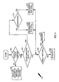
- step 104 the processor 38 determines whether the CRC for exactly one rate checks. If so, then in step 108, the processor 38 performs a one CRC check routine as described below. However, if the CRCs for none of the rates check, or if the CRCs for three or four rates check, then in step 106, the processor 38 declares the currently received frame an erasure. In general, if the CRCs for none of the rates check, then the current frame is erased.
- step 110 the processor 38 compares the SER values for the two rates that checked in step 102. For example, if the CRCs for the full and eighth rates check in step 102, then the processor 38 in step 110 determines whether the SER value for the full rate (SER 1 ) is greater than or equal to the SER value for the eighth rate (SER 8 ) plus a weighting value W determined based on the full and eighth rates (W 1,8 ). In general, the processor 38 under step 110 compares the SERs based on the following equation: SER i ⁇ SER j + W i , j , where i and j refer to the two rates corresponding to the two rates that checked under step 102.
- the weighting or scaling value W can have one of six possible values, since i and j can have one of four possible values based on the four rates (i.e., W 1,2 , W 1,4 , W 1,8 , W 2,4 , W 2,8 , and W 4,8 ). Additionally, the weighting value W can have a value ranging from -255 to +255 since the SER values have a maximum value of 255.
- the weighting value W is generally necessary because, fof the different probability densities of the SERs for the possible rates, and the differences in the chances of the CRC checking given the different actual frame rates from the transmitter.
- the weighting value W is preferably established based on empirical data provided through experimentation. By establishing a target acceptable error rate, and testing the response of the communication system of FIG.1 under the four rates, empirical data resulting therefrom is used to determine a weighting value W for each of the six combination of rates.
- the weighting value W provides an increased level of confidence as to which of the two rates the currently received frame was transmitted. Simply determining that the current rate is equal to the rate having the lower SER can result in incorrectly determining the rate of the current frame. Therefore, the SER i value must be less than the SER j value plus a weighting factor for the processor 38 to determine that the rate of the currently received frame is equal to the rate I.
- the decoder 30 will output a noisy signal that can be amplified and broadcast to a user's ear. Such a noisy signal can be perceptually undesirable to a user.
- the present invention sacrifices a little higher frame erasure rate, in exchange for not decoding a current frame at the wrong rate.
- the receiver 4 preferably attempts to maintain a frame erasure rate of less than 1%.
- the probability of the wrong rate being determined under the routines described herein are less than or equal to 10 -5 .
- the processor 38 determines that the rate of the current frame received from the transmitter 2 is at the rate i. Alternatively, if the SER i value is less than the SER j value plus W i,j , then in step 114, the processor 38 determines that the rate of the current frame received from the transmitter 2 is equal to the rate j.
- the processor 38 After determining the rate of the current frame, the processor 38 provides an appropriate signal to the buffer 40, which in response thereto, outputs the frame decoded corresponding to the determined rate or no frame if an erasure is declared.
- FIG. 3 An alternative embodiment according to the present invention for determining the received signal rate where two of the four rates check is shown in FIG. 3 as a routine 120.
- This and other alternative embodiments described below are similar to their corresponding previously described embodiment, and common steps are identified by the same reference numerals. Only the significant differences in operation are described in detail.
- the routine 120 performs the same steps 102,104, 106 and 108 as described above with respect to the routine 100.
- step 124 if the CRCs for two of the rates check under step 102, then the processor 38 employs a more accurate comparison between the SER values for the two rates identified under step 102 to further ensure that the current frame is decoded under the appropriate rate.
- the processor 38 in step 124 employs a multiplicative factor k i,j in equation (1) above, to provide the following comparative function: SER i ⁇ k i , j * SER j + W i , j .
- the multiplicative factor k i,j is preferably determined through experimentation based on empirical data for the four transmission rates. Therefore, six possible multiplicative factors are possible based on the four transmission rates (i.e., k 1,2 , k 1,4 , k 1,8 , k 2,4 , k 2,8, and k 4,8 ).
- the multiplicative factor k can simply be a normalization factor so that, for example, if i is equal to full and j is equal to half, then k 1,2 would be equal to two to normalize the half rate SER 2 value with respect to the SER 1 value.
- the multiplicative factor k can include not only a normalization factor, but compensate for differences between the different transmission rates, as described below.
- FIG. 6 a simplified diagram is shown of rate decision regions for SER values SER i and SER j , where CRCs for rates i and j check.
- the multiplicative factor k i,j determines the slope of the line, while the weighting value W i,j determines its offset from the origin (its Y-axis intercept).
- the multiplicative factor k and weighting value W vary the decision range for areas 140 and 142.
- the empirical data can be input to spreadsheets and known numerical analysis techniques can be employed under the spreadsheets to provide optimized values below the target acceptable error rate.
- routine 120 and the other routines described herein employ functions based on two rates and two SERs, SER i , SER j (i.e. f(i, j, SER i , SER j ).
- the present invention employs linear equations such as equation (2) above, and as represented in FIG. 6.
- the weighting value W, the multiplicative factor k, and the maximum and minimum SER thresholds are preferably stored in memory as a look-up table (not shown) to be accessed by the processor 38.
- step 124 the processor 38 essentially determines on which side of the line in FIG. 6 a point defined by the two SER values (SER i , SER j ) exists, to thereby determine the most likely rate for the currently received frame. If the SER i value is less than k i,j times the SER j value plus W i,j , then in step 126, the processor 38 determines whether the SER i is greater than a maximum acceptable SER threshold for rate i ( i.e ., MaxSER i ). In general, there is a maximum SER threshold value for the given rate beyond which the probability of error (of decoding at the incorrect rate) is unacceptable. As noted above, the maximum SER thresholds, shown in FIG.
- the processor 38 in step 128 determines that the rate of the currently received frame is equal to i. If, however, the SER i value is greater than or equal to the maximum SER i threshold, then in step 130 the processor 38 determines that the current frame is an erasure.
- step 124 the processor 38 determines that the SER i value is greater than or equal to k i,j times the SER j value plus W i,j . If so, the processor 38 in step 130 determines that the current frame is erased. However, if the SER j value is less than the maximum SER j threshold, then in step 134 the processor 38 determines that the current frame was transmitted at the rate j.
- a maximum SER threshold for rate j i.e ., MaxSER j
- a routine 200 is performed by the processor 38 if the CRC for only one rate checks.
- step 206 the processor 38 determines whether the SER value for the determined rate is greater than or equal to a maximum SER threshold for that rate (i.e., SER i ⁇ MaxSER i ). If it is less than the maximum, then in step 208, the processor 38 determines that the rate of the currently received frame is equal to i; otherwise, in step 210, the processor declares an erasure.
- a maximum SER threshold for that rate i.e., SER i ⁇ MaxSER i .
- step 212 the processor examines the Yamamoto value for the eighth rate (Y 8 ).
- Y 8 the Yamamoto value for the eighth rate
- the routine 200 employs additional checks to confirm that the current frame was transmitted at the eighth rate. Consequently, in step 212, if the Yamamoto value for the eighth rate checks (i.e ., provides a binary "1" value to the decoder 30), then the processor 38 has an increased level of confidence that the rate of the current frame is the eighth rate. Therefore, in step 214, the processor 38 employs a larger or looser maximum SER value for the determined rate. Such a looser maximum SER threshold improves the probability that subsequent steps under the routine 200 will appropriately determine that the current frame was transmitted at the eighth rate.
- step 216 the processor 38 selects a smaller or tighter maximum SER value for the eighth rate. If the Yamamoto value does not check, the processor 38 expects the current frame to be an erasure, and therefore makes subsequent comparisons more stringent to ensure that the current frame is determined to have been transmitted at the eighth rate under only the most stringent of comparisons. Under step 206, the processor 38 employs the looser maximum SER value from step 214, or the tighter maximum SER value from step 216, and compares it to the eighth rate SER to determine whether the frame is erased (step 210) or confirms that the current frame was transmitted at the eighth rate (step 208).
- routine 220 a more detailed analysis is shown as a routine 220.
- the processor 38 under the routine 220 performs the steps 202, 204, and 206 as discussed above. Thereafter, however, under steps 228, 230, and 232, the processor 38 compares the SER values for the three rates which did not check under step 202 ( i.e. , rates j, k, and l), to minimum SER thresholds. This reduces the chances that one of the rates decoded with a low SER is actually the correct rate though the CRC did not check for that rate.
- the steps 228, 230 and 232 determine if the SER values for the other rates are greater than minimum thresholds for that rate, and if so, declare an erasure because the probability that the current frame was transmitted at that rate outweighs the probability that the current frame was transmitted at rate i.
- step 228, the processor 38 determines whether the SER j value is less than or equal to the minimum SER threshold for the determined rate i and the rate j ( i.e ., SER i,j ). If it is, then the processor 38 declares the current frame an erasure under step 227. The reason for doing so is that the low SER of another rate (j) indicates an increased probability that the frame was transmitted at that rate (j). If it isn't, then under steps 230 and 232, the processor 38 compares the last two SER values (for rates k and l) to corresponding minimum SER thresholds for the rate i and rates k or l (SER i,k and SER i,l ), respectively.
- the processor 38 determines that the current frame was transmitted at rate i.
- the processor 38 checks the Yamamoto values for the eighth rate under step 212 as discussed above. Therefore, if the Yamamoto value for the eighth rate checks, then in step 238 the processor 38 not only employs a looser maximum SER threshold for the determined rate (the eighth rate), but also employs looser minimum SER thresholds for the determined and nondetermined rates ( i.e. , looser Min. SER i , j , SER i,k and SER i,l ).
- step 240 if the Yamamoto value does not check under step 212, then in step 240 the processor 38 not only employs a tighter maximum SER i threshold, but tighter minimum SER thresholds for the other rates ( i.e. , tighter Min. SER i,j, SER i,k and SER i,l ). Therefore, for the eighth rate, the threshold lookup table employed by the processor 38 includes two maximum threshold values for the eighth rate, and two sets of three minimum threshold values to be employed under steps 238 and 240.
- the processor 38 can compare the particular SER value to a linear function by multiplying the minimum or maximum SER threshold by the multiplicative factor k, and adding an appropriate weighting value W. For example, under step 206, the processor 38 can compare the SER value SER i to the function k i *MaxSER i + W i , while under step 228, the processor can compare the SER j value to the function k i,j * MinSER i,j + W i,j .
- a nonlinear function can be employed under steps 206-232. However, any improvement provided by a nonlinear function will likely, at best, provide only a small incremental benefit to the routine 220 and will lead to processing complexity and thus increased processing time.
- the routine 220 can be modified so that the Yamamoto values for the other rates are also checked. As a result, corresponding tighter or looser maximum and minimum SER thresholds would be employed for each of the other rates. A larger lookup table would therefore be required under such an alternative embodiment by the processor 38. Additionally, the routines 100, 120, 200 can employ such above alternatives, such as employing the Yamamoto check for each rate.
- routines of the present invention can compare the currently determined rate (rate i) to previous rates. As noted above, 90% of the time the rate of the current frame is either at the full or eighth rate in the exemplary embodiment. Similarly, under the exemplary embodiment, the probability is high that the rate of the current frame is equal to the rate of the previous frame. If a person is talking, they will likely continue talking (causing the current frame to be at the full rate), while if they are silent, they will likely continue to be silent (maintaining the current frame at the eighth rate). As a result, the above-described routines can compare the determined rate of the current frame to the rate of the previous frame, and apply looser maximum and minimum SER thresholds. Alternatively, if the current determined rate differs from the previous rate, tighter thresholds can be applied.
Abstract
Description
- The present invention relates to communications. More particularly, the present invention relates to a method and apparatus for determining transmission rate in a variable rate transmission system.
- The use of code division multiple access (CDMA) modulation techniques is one of several techniques for facilitating communications in which a large number of system users are present. Although other techniques such as time division multiple access (TDMA), frequency division multiple access (FDMA), and AM modulation schemes such as amplitude companded single sideband (ACSSB) are known, CDMA has significant advantages over these other techniques. The use of CDMA techniques in a multiple access communication system is disclosed in U.S. Patent No. 4,901,307, entitled "SPREAD SPECTRUM MULTIPLE ACCESS COMMUNICATION SYSTEM USING SATELLITE OR TERRESTRIAL REPEATERS," and assigned to the assignee of the present invention and incorporated by reference herein. The use of CDMA techniques in a multiple access communication system is further disclosed in U.S. Patent No. 5,103,459, entitled "SYSTEM AND METHOD FOR GENERATING SIGNAL WAVEFORMS IN A CDMA CELLULAR TELEPHONE SYSTEM", assigned to the assignee of the present invention.
- CDMA by its inherent nature of being a wideband signal offers a form of frequency diversity by spreading the signal energy over a wide bandwidth. Therefore, frequency selective fading affects only a small part of the CDMA signal bandwidth. Space or path diversity is obtained by providing multiple signal paths through simultaneous links from a mobile user through two or more cell-sites. Furthermore, path diversity may be obtained by exploiting the multipath environment through spread spectrum processing by allowing a signal arriving with different propagation delays to be received and processed separately. Examples of path diversity are illustrated in U.S. Patent No. 5,101,501 entitled "METHOD AND SYSTEM FOR PROVIDING A SOFT HANDOFF IN COMMUNICATIONS IN A CDMA CELLULAR TELEPHONE SYSTEM", and U.S. Patent No. 5,109,390 entitled "DIVERSITY RECEIVER IN A CDMA CELLULAR TELEPHONE SYSTEM", both assigned to the assignee of the present invention,
- CDMA systems often employ a variable rate vocoder to encode data so that the data rate can be varied from one data frame to another. An exemplary embodiment of a variable rate vocoder is described in U.S. Pat No. 5,414,796, entitled "VARIABLE RATE VOCODER," assigned to the assignee of the present invention. The use of a variable rate communications channel reduces mutual interference by eliminating unnecessary transmissions when there is no useful speech to be transmitted. Algorithms are utilized within the vocoder for generating a varying number of information bits in each frame in accordance with variations in speech activity. For example, a vocoder with a rate set of four may produce 20 millisecond data frames containing 20, 40, 80, or 160 bits; depending on the activity of the speaker. It is desired to transmit each data frame in a fixed amount of time by varying the transmission rate of communications. Additional details on the formatting of the vocoder data into data frames are described in U.S. Pat. No. 5,511,073, entitled "METHOD AND APPARATUS FOR THE FORMATTING OF DATA FOR TRANSMISSION," assigned to the assignee of the present invention,
- One technique for the receiver to determine the rate of a received data frame is described in U.S. patent 5566206. entitled "METHOD AND APPARATUS FOR DETERMINING DATA RATE OF TRANSMITTED VARIABLE RATE DATA IN A COMMUNICATIONS RECEIVER," assigned to the assignee of the present invention Another technique is described in European Patent Application 0720797 entitled "MULTIRATE SERIAL VITERBI DECODER FOR CODE DIVISION MULTIPLE ACCESS SYSTEM APPLICATIONS," assigned to the assignee of the present invention According to these techniques, each received data frame is decoded at each of the possible rates. Error metrics, which describe the quality of the decoded symbols for each frame decoded at each rate, are provided to a processor. The error metrics may include Cyclic Redundancy Check (CRC) results, Yamamoto Quality Metrics, and Symbol Error Rates. These error metrics are well-known in communications systems. The processor analyzes the error metrics and determines the most probable rate at which the incoming symbols were transmitted. '
- Further attention is drawn to the document US A 5,509,020, which discloses a received data decoder apparatus, which receives and decodes transmitted convolutional code data. The received data is formed of a first channel whose data rate is fixed and a second channel whose data rate is variable. The received data decoding apparatus includes a most likelihood decoder for decoding the received data on the basis of a Viterbi algorithm and a data rate decision unit for obtaining a predetermined data rate of the second channel determined according to a path metric amount which is a decoded output from the most likelihood decoder.
- In accordance with the present invention a method for determining a current rate of a current frame, as set forth in
claim 1, a receiver as set forth in claim 17, and a communication system, as set forth inclaim 34, are provided. Preferred embodiments of the present invention are claimed in the dependent claims. - The present invention provides a novel and improved apparatus and method for decoding data. The apparatus and method are employed in a communications system having a transmitter and a receiver, where the receiver determines at which of several rates individual frames in a signal has been transmitted by the transmitter. For example, if the transmitter employs four transmission rates, the receiver decodes each frame of the received signal based on the four rates to produce four cyclic redundancy check (CRC) bits, four symbol error rate (SER) values and one or more Yamamoto check values. If the CRC checks for only two rates, then the receiver compares to each other the SER values for those two rates to determine at which of the two rates a current frame was transmitted. If the CRC checks for only one rate, then the SER value for that rate is compared with a maximum SER threshold for that rate. Additionally, SER values for the other rates can be compared to minimum SER thresholds. Furthermore, the Yamamoto check values can be analyzed to determined whether looser or tighter minimum and maximum SER thresholds should be employed if the Yamamoto values check for the current rate, or do not check, respectively.
- Broadly stated, the present invention embodies a method for use in a communication system having a transmitter and a receiver. The transmitter transmits a signal at a current rate, wherein the current rate corresponds to one of a plurality of rates. The receiver generates a plurality of check error values and error rate codes, and at least one decoding code, each based on whether the signal has one of the plurality of rates. The method determines the current rate of the signal and includes the steps of: (a) determining if only a first check value of a selected rate favorably checks, wherein the selected rate is one of the plurality of rates; (b) determining if the selected rate corresponds to a predetermined rate; (c) if the selected rate corresponds to the predetermined rate, comparing a selected decoding code to a selected value; (d) if the selected rate does not correspond to the predetermined rate, comparing a selected error rate code to a first value based on a predetermined operational relationship, wherein the selected rate code corresponds to the selected rate; (e) if the selected decoding code corresponds to the selected value, comparing the selected error rate code to a second value based on the predetermined operational relationship; (f) if the selected decoding code does not correspond to the selected value, comparing the selected error rate code to a third value based on the predetermined operational relationship; and (g) determining that the current rate of the signal is the selected rate if the selected error rate code has the predetermined operational relationship to the first, second or third values.
- Broadly stated, the present invention also embodies a method for determining the current rate of the signal having the steps of: (a) determining that only first and second error check values of first and second rates favorably check, wherein the first and second rates are from the plurality of rates; (b) comparing a first error rate code to a second error rate code plus a first value based on a predetermined operational relationship, wherein the first and second error rate codes correspond to the first and second rates; and (c) determining that the current rate of the signal is the second rate if the first error rate code has the predetermined operational relationship to the second error rate code plus a first value, and otherwise determining that the current rate is the first rate.
- The features, objects, and advantages of the present invention will become more apparent from the detailed description set forth below when taken in conjunction with the drawings in which like reference characters identify correspondingly throughout and wherein:
- FIG.1 is a block diagram of the communication system of the present invention;
- FIG. 2 is a flowchart illustrating a method for selecting the decoded frame when the CRC checks for two different rates;
- FIG. 3 is a flowchart illustrating an alternative method for selecting the decoded frame when the CRC checks for two different rates;
- FIG. 4 is a flowchart illustrating a method for selecting the decoded frame when the CRC checks for one rate;
- FIG. 5 is a flowchart illustrating an alternative method for selecting the decoded frame when the CRC checks for one rate; and
- FIG. 6 is a plot of rate decision regions for symbol error rates i and j where the CRC checks for both rates i and j.
- Referring to FIG. 1, a
remote transmission system 2 transmits data to a remote receiving system 4. In an exemplary embodiment, the present invention is implemented in a wireless communication system which communicates using spread spectrum modulation signals. Communication using spread spectrum communication systems is described in detail in the aforementioned U.S. Patents 4,901,307 and 5,103,459. - A variable
rate data source 6 provides variable rate data frames for transmission to a Cyclic Redundancy Check (CRC) andTail Bit Generator 8. In the exemplary embodiment, thedata source 6 is a variable rate vocoder for encoding speech information at four variable rates as described in detail in the aforementioned U.S Patent No. 5,414,796. When used, for example, in a cellular telephone environment, the signal is transmitted at the full rate to transmit speech (i.e., when a user is talking) and is transmitted at the eighth rate to transmit silence (i.e., when the user is not talking). The eighth rate saves on the number of bits transmitted, and thereby saves on power. In general, 90% of the signals transmitted by thetransmitter 2 to the receiver 4 are either at the full or one-eighth rate. The one-half and one-quarter rates represent transitional rates between the full and eighth rates. - The
generator 8 generates a set of CRC bits to provide for error detection at the receiver as is well known in the art. In addition, thegenerator 8 appends a sequence of tail bits to the frame. In the exemplary embodiment, thegenerator 8 generates the set of CRC and tail bits in accordance with the Telecommunications Industry Association's TIA/EIA/IS-95-A Mobile Stations-Base Station Compatibility Standard for Dual-Mode Wideband Spread Spectrum Cellular System. - The data frame is provided by the
generator 8 to anencoder 10 which encodes the data as symbols for error correction and detection at the receiver. In the exemplary embodiment, theencoder 10 is arate 1/2 convolutional encoder. The encoded symbols are provided to aninterleaver 12, which reorders the encoded symbols in accordance with a predetermined interleaving format. In the exemplary embodiment, theinterleaver 12 is a block interleaver, the design and implementation of which is well known in the art. - The reordered frame is then provided to a
modulator 14 which modulates the frame for transmission. In the exemplary embodiment, themodulator 14 is a CDMA modulator, the implementation of which is described in detail in the aforementioned U.S. Patents 4,901,307 and 5,103,459. The modulated data frame is provided to a transmitter (TMTR) 16. Thetransmitter 16 upconverts and amplifies the signal for transmission through anantenna 18. - The transmitted signal is received by an
antenna 20 of a remote station 4, such as a cellular phone, and provided to a receiver (RCVR) 22 which down converts and amplifies the received signal. The received signal is then provided to a demodulator (DEMOD) 24 which demodulates the signal. In the exemplary embodiment, thedemodulator 24 is aCDMA demodulator 24, the implementation of which is described in detail in the aforementioned U.S. Patents 4,901,307 and 5,103,459. - The demodulated signal is then provided to a
diversity combiner 26. Thediversity combiner 26 combines the demodulated signal from thedemodulator 24 with demodulated signals from other demodulators (not shown) which demodulate the same signal except provided on a different propagation path. The design and implementation of thediversity combiner 26 is described in detail in the aforementioned U.S. Patent No. 5,109,390. The diversity combined signal is provided to a de-interleaver 28 which re-orders the symbols in the frame in accordance with a predetermined re-ordering format as is well known in the art. - The re-ordered frame is then provided to a
multi-rate decoder 30, which provides error correction on the frame of symbols. Thedecoder 30 decodes the data based on a predetermined set of rate hypotheses. In the exemplary embodiment, thedecoder 30 is a multi-rate Viterbi decoder as is described in detail in the aforementioned copending U.S. Patent Application Serial No. 08/126,477. - In the exemplary embodiment, the
decoder 30 decodes the symbols for each of the four possible rates to provide four separately decoded frames of data, each of which is provided to aCRC check detector 32. TheCRC check detector 32 determines under conventional techniques whether the cyclic redundancy check bits for each frame are correct for the decoded data. TheCRC check detector 32 performs a CRC check for the CRC bits in the four decoded frames to help determine whether the currently received frame was transmitted at the full, half, quarter or eighth rates. As a result, theCRC check detector 32 provides four check bits, C1, C2, C4 and C8, where a binary value of "1" for a given CRC check bit can indicate that the CRC check matched or checked, while a binary value of "0" can indicate that the CRC bits did not check. As used generally herein, the subscript or indication "1" corresponds to the full rate, "2" corresponds to the half rate, "4" corresponds to the quarter rate and "8" corresponds to the eighth rate. - In addition, the
decoder 30 provides the decoded data to a symbol error rate (SER)check detector 34. TheSER detector 34 receives the decoded bits and an estimate of the received symbol data from thedecoder 30. As is known, theSER detector 34 re-encodes the decoded bits, and compares them to the estimate of the received symbol data from thedecoder 30. The SER is a count of the number of discrepancies between the re-encoded symbol data and the received symbol data. Therefore, theSER detector 34 generates four SER values: SER1, SER2, SER4 and SER8. For processing efficiency, theSER detector 34 provides SER values having a maximum value of 255. In addition to the CRC bits, the SER values help provide a determination of the rate of the current frame transmitted by thetransmitter 2, and whether the frame has errors. - Furthermore, the
decoder 30 provides information to aYamamoto check detector 36 which provides a confidence metric based on the difference between the selected path through a trellis and the next closest path through the trellis. While the CRC check is dependent on the bits in each of the four decoded frames, the Yamamoto check is dependent on the decoding process of the receiver 4. TheYamamoto detector 36, as with thedetectors detectors decoder 30. - A control processor 38 receives the CRC check bits, SER values and Yamamoto values from the
detectors decoder 30 provides four decoded frames for storage in a decoded frame buffer 40, where each of the four frames is decoded under one of the four rates. Based on the rate determined by the processor 38, the control processor provides a signal to the decoded frame buffer 40, which in response thereto, outputs the stored frame decoded at the determined rate or outputs no frame if an erasure is declared. In an alternative embodiment, decoder frame buffer 40 outputs a signal indicative of a frame erasure if an erasure is declared. - Under the communication system of FIG. 1, the signal transmitted by the
transmitter 2 to the receiver 4 can rapidly change between the four rates. As a result, thetransmitter 2 does not include within the transmitted signal an actual indication as to the rate at which the signal is currently being transmitted. To do so would require unnecessary bandwidth. Therefore, thetransmitter 2 transmits a frame at a current rate (selected from one of the four rates), and a control processor 38 and thedecoder 30 of the receiver 4, under routines described below, determine at which of the four rates the currently received frame was sent or whether an erasure should be declared (i.e., whether the current frame was sent at the full, half, quarter or eighth rate). Thedecoder 30 then decodes the one of the four decoded frames which has the determined rate and outputs a decoded signal. The appropriately decoded signal can then be input to, for example, a vocoder, amplifier and speaker (not shown) to output a voice signal to be heard by a user of the receiver 4. - The control processor 38, coupled to at least the
decoder 30, operates in conjunction with the methods illustrated in the flow diagrams of FIGS. 2-5 to select the appropriate decoded frame to be output or provided to the user, or to declare the current frame an erasure condition. While the control processor 38 anddecoder 30 are shown as separate elements, the control processor and decoder can be incorporated together to form a single decoder. - Referring to FIG. 2, an
exemplary routine 100 performed by the processor 38 first determines instep 102 whether the CRC checks for two of the four rates. For example, if the processor 38 determines that the CRC for the full and eighth rates check (i.e., bits C1 = C8 = 1), but the CRCs do not check for the half and quarter rates (i.e., bits C2 = C4 =0), then the processor 38 determines thatstep 102 is satisfied. If the CRCs for exactly two rates check instep 102, then the current frame can have three possible interpretations: - it could be erased, it could have been transmitted at a first rate i corresponding to the first rate that checked its CRC, or it could have been transmitted at a second rate j corresponding to the second rate that checked its CRC.
- However, if the CRCs for less than two or greater than two of the rates check, then in
step 104, the processor 38 determines whether the CRC for exactly one rate checks. If so, then instep 108, the processor 38 performs a one CRC check routine as described below. However, if the CRCs for none of the rates check, or if the CRCs for three or four rates check, then instep 106, the processor 38 declares the currently received frame an erasure. In general, if the CRCs for none of the rates check, then the current frame is erased. Alternatively, if the CRCs for three or four of the rates check, then, while the processor 38 could still determine the current rate of the currently received frame, such a determination is computationally difficult, can have a higher probability of error, and generally requires too much processing overhead to rapidly and accurately determine the rate for the current frame. Therefore, it is simply easier for the processor 38 to declare the current frame an erasure. - If the CRCs for two rates check in
step 102, then instep 110, the processor 38 compares the SER values for the two rates that checked instep 102. For example, if the CRCs for the full and eighth rates check instep 102, then the processor 38 instep 110 determines whether the SER value for the full rate (SER1) is greater than or equal to the SER value for the eighth rate (SER8) plus a weighting value W determined based on the full and eighth rates (W1,8). In general, the processor 38 understep 110 compares the SERs based on the following equation:
where i and j refer to the two rates corresponding to the two rates that checked understep 102. - The weighting or scaling value W can have one of six possible values, since i and j can have one of four possible values based on the four rates (i.e., W1,2, W1,4, W1,8, W2,4, W2,8, and W4,8). Additionally, the weighting value W can have a value ranging from -255 to +255 since the SER values have a maximum value of 255. The weighting value W is generally necessary because, fof the different probability densities of the SERs for the possible rates, and the differences in the chances of the CRC checking given the different actual frame rates from the transmitter. The weighting value W is preferably established based on empirical data provided through experimentation. By establishing a target acceptable error rate, and testing the response of the communication system of FIG.1 under the four rates, empirical data resulting therefrom is used to determine a weighting value W for each of the six combination of rates.
- In general, the weighting value W provides an increased level of confidence as to which of the two rates the currently received frame was transmitted. Simply determining that the current rate is equal to the rate having the lower SER can result in incorrectly determining the rate of the current frame. Therefore, the SERi value must be less than the SERj value plus a weighting factor for the processor 38 to determine that the rate of the currently received frame is equal to the rate I.
- Sometimes, it is less desirable to decode a current frame at an incorrect rate than to declare a current frame an erasure. This is accomodated in the present invention. If a current frame is decoded at the wrong rate, the
decoder 30 will output a noisy signal that can be amplified and broadcast to a user's ear. Such a noisy signal can be perceptually undesirable to a user. As a result, the present invention sacrifices a little higher frame erasure rate, in exchange for not decoding a current frame at the wrong rate. Nevertheless, the receiver 4 preferably attempts to maintain a frame erasure rate of less than 1%. Preferably, the probability of the wrong rate being determined under the routines described herein are less than or equal to 10-5. - If the SERi value is greater than or equal to the SERj value plus the weighting value Wi,j, then in
step 112, the processor 38 determines that the rate of the current frame received from thetransmitter 2 is at the rate i. Alternatively, if the SERi value is less than the SERj value plus Wi,j, then instep 114, the processor 38 determines that the rate of the current frame received from thetransmitter 2 is equal to the rate j. In the above example, where i and j correspond to the full and eighth rates, respectively, if the SER1 value is greater than or equal to the SER8 value plus the weighting value W1,8, then the rate of the currently received frame is equal to the full rate understep 112, otherwise, the rate is equal to the one-eighth rate understep 114. After determining the rate of the current frame, the processor 38 provides an appropriate signal to the buffer 40, which in response thereto, outputs the frame decoded corresponding to the determined rate or no frame if an erasure is declared. - An alternative embodiment according to the present invention for determining the received signal rate where two of the four rates check is shown in FIG. 3 as a routine 120. This and other alternative embodiments described below are similar to their corresponding previously described embodiment, and common steps are identified by the same reference numerals. Only the significant differences in operation are described in detail.
- Referring to FIG. 3, the routine 120 performs the same steps 102,104, 106 and 108 as described above with respect to the routine 100. In
step 124, if the CRCs for two of the rates check understep 102, then the processor 38 employs a more accurate comparison between the SER values for the two rates identified understep 102 to further ensure that the current frame is decoded under the appropriate rate. Specifically, the processor 38 instep 124 employs a multiplicative factor ki,j in equation (1) above, to provide the following comparative function:
As with the weighting value W, the multiplicative factor ki,j is preferably determined through experimentation based on empirical data for the four transmission rates. Therefore, six possible multiplicative factors are possible based on the four transmission rates (i.e., k1,2, k1,4, k1,8, k2,4, k2,8, and k4,8). The multiplicative factor k can simply be a normalization factor so that, for example, if i is equal to full and j is equal to half, then k1,2 would be equal to two to normalize the half rate SER2 value with respect to the SER1 value. Alternatively, the multiplicative factor k can include not only a normalization factor, but compensate for differences between the different transmission rates, as described below. - Referring to FIG. 6, a simplified diagram is shown of rate decision regions for SER values SERi and SERj, where CRCs for rates i and j check. In general, a line SERi = ki,j * SERj + Wi,j separates an SERi region 140 from an SERj region 142. As a result, the multiplicative factor ki,j determines the slope of the line, while the weighting value Wi,j determines its offset from the origin (its Y-axis intercept). In general, the multiplicative factor k and weighting value W vary the decision range for
areas - One can build probability density curves based on the empirical data collected through experimentation and define a target acceptable error rate. Thereafter, one can integrate under a portion of the probability density curves, below the target acceptable error rate, to determine minimum and maximum SER threshold values (discussed below), for each rate. The empirical data can be input to spreadsheets and known numerical analysis techniques can be employed under the spreadsheets to provide optimized values below the target acceptable error rate. In sum, one can determine through experimentation the probabilities that the current rate is i based on given SER values, where these probabilities are then plotted based on the SERi value and the SER values for the other rates (e.g., SERj).
- In general, the routine 120 and the other routines described herein employ functions based on two rates and two SERs, SERi, SERj (i.e. f(i, j, SERi, SERj). Under the exemplary embodiment, the present invention employs linear equations such as equation (2) above, and as represented in FIG. 6. The weighting value W, the multiplicative factor k, and the maximum and minimum SER thresholds (discussed below) are preferably stored in memory as a look-up table (not shown) to be accessed by the processor 38.
- In
step 124, the processor 38 essentially determines on which side of the line in FIG. 6 a point defined by the two SER values (SERi, SERj) exists, to thereby determine the most likely rate for the currently received frame. If the SERi value is less than ki,j times the SERj value plus Wi,j, then instep 126, the processor 38 determines whether the SERi is greater than a maximum acceptable SER threshold for rate i (i.e., MaxSERi). In general, there is a maximum SER threshold value for the given rate beyond which the probability of error (of decoding at the incorrect rate) is unacceptable. As noted above, the maximum SER thresholds, shown in FIG. 6, are determined based on empirical data derived through experimentation with the four rates. If the SERi value is less than the maximum SERi threshold, then the processor 38 instep 128 determines that the rate of the currently received frame is equal to i. If, however, the SERi value is greater than or equal to the maximum SERi threshold, then instep 130 the processor 38 determines that the current frame is an erasure. - If, under
step 124, the processor 38 determines that the SERi value is greater than or equal to ki,j times the SERj value plus Wi,j, then instep 132, the processor 38 determines whether the SERj value is greater than or equal to a maximum SER threshold for rate j (i.e., MaxSERj). If so, the processor 38 instep 130 determines that the current frame is erased. However, if the SERj value is less than the maximum SERj threshold, then instep 134 the processor 38 determines that the current frame was transmitted at the rate j. - Referring to FIG. 4, a routine 200 is performed by the processor 38 if the CRC for only one rate checks. As with step 104 (FIG. 2), the processor 38 in
step 202 first determines whether the CRC for exactly one rate checks. If not, then instep 203, the processor 38 declares the current frame to be an erasure, or performs the twoCRC check routine step 202, the processor 38 under the routine 200 employs additional steps to confirm that the rate which checked understep 202 is in fact the correct rate for the current frame. Therefore, instep 204, the processor 38 determines whether the rate which checked understep 202 corresponds to the eighth rate (i.e., i = 8). If not, then instep 206, the processor 38 determines whether the SER value for the determined rate is greater than or equal to a maximum SER threshold for that rate (i.e., SERi ≥ MaxSERi). If it is less than the maximum, then instep 208, the processor 38 determines that the rate of the currently received frame is equal to i; otherwise, instep 210, the processor declares an erasure. - If in
step 204 the processor 38 determines that the indicated rate is equal to the eighth rate, then instep 212, the processor examines the Yamamoto value for the eighth rate (Y8). As is known, a frame at the eighth rate has fewer CRC bits than frames at the other rates, and as a result, the CRC more often. Therefore, the routine 200 employs additional checks to confirm that the current frame was transmitted at the eighth rate. Consequently, instep 212, if the Yamamoto value for the eighth rate checks (i.e., provides a binary "1" value to the decoder 30), then the processor 38 has an increased level of confidence that the rate of the current frame is the eighth rate. Therefore, instep 214, the processor 38 employs a larger or looser maximum SER value for the determined rate. Such a looser maximum SER threshold improves the probability that subsequent steps under the routine 200 will appropriately determine that the current frame was transmitted at the eighth rate. - Conversely, if the Yamamoto value does not check in
step 212, then instep 216 the processor 38 selects a smaller or tighter maximum SER value for the eighth rate. If the Yamamoto value does not check, the processor 38 expects the current frame to be an erasure, and therefore makes subsequent comparisons more stringent to ensure that the current frame is determined to have been transmitted at the eighth rate under only the most stringent of comparisons. Understep 206, the processor 38 employs the looser maximum SER value fromstep 214, or the tighter maximum SER value fromstep 216, and compares it to the eighth rate SER to determine whether the frame is erased (step 210) or confirms that the current frame was transmitted at the eighth rate (step 208). - Referring to FIG. 5, a more detailed analysis is shown as a routine 220. The processor 38 under the routine 220 performs the
steps steps steps - Therefore, in
step 228, the processor 38 determines whether the SERj value is less than or equal to the minimum SER threshold for the determined rate i and the rate j (i.e., SERi,j). If it is, then the processor 38 declares the current frame an erasure understep 227. The reason for doing so is that the low SER of another rate (j) indicates an increased probability that the frame was transmitted at that rate (j). If it isn't, then understeps steps step 227. However, if such SER values are greater than the minimum, then instep 234 the processor 38 determines that the current frame was transmitted at rate i. - As under the routine 200, if the rate which checked under
step 202 is determined to be the eighth rate instep 204, then the processor 38 checks the Yamamoto values for the eighth rate understep 212 as discussed above. Therefore, if the Yamamoto value for the eighth rate checks, then instep 238 the processor 38 not only employs a looser maximum SER threshold for the determined rate (the eighth rate), but also employs looser minimum SER thresholds for the determined and nondetermined rates (i.e., looser Min. SERi,j, SERi,k and SERi,l). Similarly, understep 240, if the Yamamoto value does not check understep 212, then instep 240 the processor 38 not only employs a tighter maximum SERi threshold, but tighter minimum SER thresholds for the other rates (i.e., tighter Min. SERi,j, SERi,k and SERi,l). Therefore, for the eighth rate, the threshold lookup table employed by the processor 38 includes two maximum threshold values for the eighth rate, and two sets of three minimum threshold values to be employed understeps - Various alternatives to the various routines are available. For example, rather than simply comparing the determined and other SER values under
steps step 206, the processor 38 can compare the SER value SERi to the function ki*MaxSERi + Wi, while understep 228, the processor can compare the SERj value to the function ki,j * MinSERi,j + Wi,j. Moreover, a nonlinear function can be employed under steps 206-232. However, any improvement provided by a nonlinear function will likely, at best, provide only a small incremental benefit to the routine 220 and will lead to processing complexity and thus increased processing time. - While the Yamamoto values are checked only for the eighth rate, the routine 220 can be modified so that the Yamamoto values for the other rates are also checked. As a result, corresponding tighter or looser maximum and minimum SER thresholds would be employed for each of the other rates. A larger lookup table would therefore be required under such an alternative embodiment by the processor 38. Additionally, the
routines - Rather than employing a lookup table having the weighting values W, multiplicative factors k, and minimum and maximum SER thresholds, such values could be algorithmically computed under appropriate equations. However, such equations are complex, and would require significant overhead of the processor 38. As a result, a faster, and therefore more expensive, microprocessor 38 would be required under such an alternative.
- Furthermore, the routines of the present invention can compare the currently determined rate (rate i) to previous rates. As noted above, 90% of the time the rate of the current frame is either at the full or eighth rate in the exemplary embodiment. Similarly, under the exemplary embodiment, the probability is high that the rate of the current frame is equal to the rate of the previous frame. If a person is talking, they will likely continue talking (causing the current frame to be at the full rate), while if they are silent, they will likely continue to be silent (maintaining the current frame at the eighth rate). As a result, the above-described routines can compare the determined rate of the current frame to the rate of the previous frame, and apply looser maximum and minimum SER thresholds. Alternatively, if the current determined rate differs from the previous rate, tighter thresholds can be applied.
- The teachings provided herein of the present invention can be applied to other communication systems, not necessarily the exemplary spread spectrum communications system described above. The present invention can employ the systems and methods of various patents and applications described above.
- These and other changes can be made to the invention in light of the above detailed description. In general, in the following claims, the terms used should not be construed to limit the invention to the specific embodiments disclosed in the specification and the claims, but should be construed to include any communications system that operates under the claims to provide rate determination. Accordingly, the invention is not limited by the disclosure, but instead its scope is to be determined entirely by the following claims.
Claims (34)
- A method for determining a current rate of a current frame for a communication system having a transmitter (2) and a receiver (4), said transmitter (2) transmitting each of a plurality of frames at the current rate, wherein said current rate corresponds to one of a plurality of rates, said method comprising the steps of:generating a plurality of error check values each based on whether said current frame has one of said plurality of rates, wherein only a first check value of a selected rate favorably checks, and wherein said selected rate is one of said plurality of rates;generating a plurality of error rate values each based on whether said current frame has one of said plurality of rates, wherein a selected error rate value corresponds to said selected rate;generating a plurality of decoding values each based on whether said current frame has one of said plurality of rates, wherein a selected decoding value corresponds to said selected rate;determining (204) if said selected rate of said selected error rate value corresponds to a predetermined rate;if said selected rate corresponds to said predetermined rate, comparing (212) said selected decoding value to a selected value;if said selected rate does not correspond to said predetermined rate, comparing (206) said selected error rate value to a first value based on a predetermined relationship;if said selected decoding value corresponds to said selected value, comparing (214) said selected error rate value to a second value based on said predetermined relationship;if said selected decoding value does not correspond to said selected value, comparing (216) said selected error rate value to a third value based on said predetermined relationship; anddetermining (208) that said current rate of said current frame is said selected rate if said selected error rate value has said predetermined relationship to said first, second or third value.
- The method of claim 1 wherein the step of generating a plurality of error check values generates a plurality of cyclic redundancy check values, wherein the step of generating a plurality of error rate values generates a plurality of symbol error rates, and wherein the step of generating a plurality of decoding values generates a plurality of Yamamoto check values
- The method of claim 1 wherein said plurality of rates include full, half, quarter and eighth rates, and wherein the step of determining (204) if said selected rate of said selected error rate value corresponds to a predetermined rate determines if said selected rate corresponds to said eighth rate.
- The method of claim 1 wherein the step of generating a plurality of decoding values generates a plurality of Yamamoto check values, and wherein the step of comparing (212) said selected decoding value to a selected value includes the step of determining if said selected Yamamoto value checks acceptably.
- The method of claim 1 wherein said first, second and third values are error rate value threshold values, wherein the steps of comparing (206, 216, 214) said selected error rate value to said first, second and third values determines whether said selected error rate value is less than said first, second and third threshold values, respectively, and wherein said second threshold value is greater than said third threshold value.
- The method of claim 1 wherein the step of determining (206) that said current rate of said current frame is said selected rate includes the step of determining (210) that said current frame is erased if said selected error rate value does not have said predetermined relationship to said first, second or third value.
- The method of claim 1, further comprising the steps of: comparing at least another of said error rate values to a minimum threshold error rate value based on a selected relationship; and determining that said current frame is erased if said another of said error rate values has said selected relationship to said minimum threshold.
- The method of claim 1, wherein said transmitter is transmitting a signal formed by said plurality of frames and said method is for determining a current rate of said signal wherein said receiver (4) generates said plurality of error check values and said error rate values and at least one decoding value each based on whether said signal has one of said plurality of rates.
- The method of claim 8 wherein said plurality of rates include full, half, quarter and eighth rates, and wherein the step of determining (208) if said selected rate corresponds to a predetermined rate determines if said selected rate corresponds to said eighth rate.
- The method of claim 8 wherein said selected decoding value is a Yamamoto check value, and wherein the step of comparing (212) a selected decoding value to a selected value includes the step of determining if said selected Yamamoto value checks acceptably.
- The method of claim 8 wherein said first, second and third values are error rate value threshold values, wherein the steps of comparing (206, 216, 214) said selected error rate value to said first, second and third values determines whether said selected error rate value is less than said first, second and third threshold values, respectively, and wherein said second threshold value is greater than said third threshold value.
- The method of claim 8 wherein said signal includes a plurality of frames including a current frame, and wherein the step of determining (208) that said current rate of said signal is said selected rate includes the step of determining that said current frame is erased if said selected error rate value does not have said predetermined relationship to said first, second or third value.
- The method of claim 8, further comprising the steps of: comparing at least another of said error rate values to a minimum threshold error rate value based on a selected relationship; and determining that said signal is erroneous if said another of said error rate values has said selected relationship to said minimum threshold.
- The method of claim 8 wherein the steps of comparing include the step of comparing said selected error rate value to first, second and third weighting values plus said first, second and third values, respectively.
- The method of claim 8 wherein the steps of comparing include the step of comparing said selected error rate value to first, second and third multiplicative factor times said first, second and third values, respectively.
- The method of claim 8 wherein said first value is an error rate value threshold value, and wherein the method further includes the steps of: comparing said selected rate to a previous rate; decreasing said first threshold value if said selected rate and said previous rate are approximately equal; and increasing said first threshold rate if said selected rate and said previous rate are not equal.
- A receiver (4) for a communication system having a transmitter (2) that transmits a signal at a current rate, and wherein said current rate corresponds to one of a plurality of rates, said receiver (4) comprising:an error check value generator (32) configured to generate a plurality of error check values each based on whether said signal has one of said plurality of rates, wherein only a first check value of a selected rate favorably checks, and wherein said selected rate is one of said plurality of rates;an error rate value generator (34) configured to generate a plurality of error rate values each based on whether said signal has one of said plurality of rates, wherein a selected error rate value corresponds to said selected rate;a decoding value generator (36) configured to generate at least a selected decoding value, based on whether said signal has said selected rate; anda decoder (30) coupled to said error check value generator (32), error rate value generator (34) and decoding value generator (36) and configured to (a) determine if said selected rate of said selected error rate value corresponds to a predetermined rate, (b) compare said selected decoding value to a selected value if said selected rate corresponds to said predetermined rate, (c) compare said selected error rate value to a first value based on a predetermined relationship if said selected rate does not correspond to said predetermined rate, (d) compare said selected error rate value to a second value based on said predetermined relationship if said selected decoding value corresponds to said selected value, (e) compare said selected error rate value to a third value based on said predetermined relationship if said selected decoding value does not correspond to said selected value, (f) determine that said current rate of said signal is said selected rate if said selected error rate value has said predetermined relationship to said first, second or third value, and (g) decode said signal based on said selected rate.
- The receiver (4) of claim 17 wherein said error check value generator (32) generates a plurality of cyclic redundancy check values, wherein said error rate value generator generates a plurality of symbol error rates, and wherein said decoding value generator generates a plurality of Yamamoto check values.
- The receiver (4) of claim 17 wherein said plurality of rates include full, half, quarter and eighth rates, and wherein said decoder determines if said selected rate corresponds to said eighth rate.
- The receiver (4) of claim 17 wherein said decoding value generator (36) generates a plurality of Yamamoto check values, and wherein said decoder determines if said selected Yamamoto value checks acceptably.
- The receiver (4) of claim 17 wherein said first, second and third values are error rate value threshold values, wherein said decoder (30) determines whether said selected error rate value is less than said first, second and third values, respectively, and wherein said second threshold value is greater I than said third threshold value.
- The receiver (4) of claim 17 wherein said signal includes a plurality of frames, including a current frame, and wherein said decoder determines that said current frame is erased if said selected error rate value does not have said predetermined relationship to said first, second or third value.
- The receiver (4) of claim 17 wherein said decoder (30) compares at least another of said error rate values to a minimum threshold based on a selected relationship, and determines that said signal is erroneous if said another of said error rate values has said selected relationship to said minimum threshold.
- The receiver (4) of claim 17 wherein said decoder (30) compares said selected error rate value to first, second and third weighting values plus said first, second and third values, respectively.
- The receiver (4) of claim 17 wherein said decoder (30) compares said selected error rate value to first, second and third multiplicative factors times said first, second and third values, respectively.
- The receiver (4) of claim 17 wherein said decoder (30) compares said selected rate to a previous rate and decreases said first value if said selected rate and said previous rate are approximately equal.
- The receiver (4) of claim 17 wherein said transmitter transmits to the receiver (4) plurality of frames said plurality of frames forming said signal.
and wherein said error check value generator comprises means (32) for generating said plurality of error check values each based on whether said current frame has one of said plurality of rates, wherein only a first check value of a selected rate favorably checks, and wherein said selected rate is one of said plurality of rates;
and wherein said error rate value generator comprises means (34) for generating said plurality of error rate values each based on whether said current frame has one of said plurality of rates, wherein a selected error rate value corresponds to said selected rate;
and wherein said decoding, value generator comprises means (36) for generating said at least one decoding value, each decoding value being based on whether said current frame has one of said plurality of rates, wherein a selected decoding value corresponds to said selected rate; and wherein said decoder comprises
means, coupled to said means (34) for generating a plurality of error rate values, for determining if said selected rate of said selected error rate value corresponds to said predetermined rate;
means, coupled to said means (36) for generating a plurality of decoding values, for comparing said selected decoding value to said-selected value if said selected rate corresponds to said predetermined rate;
means, coupled to said means (34) for generating a plurality of error rate values, for comparing said selected error rate value to said -first value based on said predetermined relationship if said selected rate does not correspond to said predetermined rate for comparing said selected error rate value to said second value based on said predetermined relationship if said selected decoding value corresponds to said selected value, and for comparing said selected error rate value to said third value based on said predetermined relationship if said selected decoding value does not correspond to said selected value;
and means, coupled to said means for comparing said first, second and third values, for determining that said current rate of said current frame is said selected rate if said selected error rate value has said predetermined relationship to said first, second or third value. - The receiver (4) of claim 27 wherein said means (32) for generating a plurality of error check values generates a plurality of cyclic redundancy check values, wherein said means for generating a plurality of error rate values generates a plurality of symbol error rates, and wherein said means for generating a plurality of decoding values generates a plurality of Yamamoto check values.
- The receiver (4) of claim 27wherein said plurality of rates include full, half, quarter and eighth rates, and wherein said means for determining if said selected rate of said selected error rate value corresponds to a predetermined rate includes means for determining if said selected rate corresponds to said eighth rate.
- The receiver (4) of claim 27 wherein said means for generating a plurality of decoding values generates a plurality of Yamamoto check values, and wherein said means for comparing said selected decoding value to a selected value includes means for determining if said selected Yamamoto value checks acceptably.
- The receiver (4) of claim 27 wherein said first, second and third values are error rate value threshold values, wherein said means for comparing said selected error rate value to said first, second and third values includes means for determining whether said selected error rate value is less than said first, second and third threshold values, respectively, and wherein said second threshold value is greater than said third threshold value.
- The receiver (4) of claim 27 wherein said means for determining that said current rate of said current frame is said selected rate includes means for determining that said current frame is erased if said selected error rate value does not have said predetermined relationship to said first, second or third value.
- The receiver (4) of claim 27, further comprising: means for comparing at least another of said error rate values to a minimum threshold error rate value based on a selected relationship; and means for determining that said current frame is erased if said another of said error rate values has said selected relationship to said minimum threshold.
- A communication system comprising:a transmitter (2) configured to transmit a signal at a current rate, wherein said current rate corresponds to one of a plurality of rates; anda receiver (4) configured to receive said signal, said receiver including:an error check value generator (32) configured to generate a plurality of error check values each based on whether said signal has one of said plurality of rates, wherein only a first check value of a selected rate favorably checks, and wherein said selected rate is one of said plurality of rates;an error rate value generator (34) configured to generate a plurality of error rate values each based on whether said signal has one of said plurality of rates, wherein a selected error rate value corresponds to said selected rate;a decoding value generator (36) configured to generate a plurality of decoding values each based on whether said signal has one of said plurality of rates, wherein a selected decoding value corresponds to said selected rate; anda decoder (30) coupled to said error check value generator (32), error rate value generator (34) and decoding value generator (36) and configured to (a) determine if said selected rate of said selected error rate value corresponds to a predetermined rate, (b) compare said selected decoding value to a selected value if said selected rate corresponds to said predetermined rate, (c) compare said selected error rate value to a first value based on a predetermined relationship if said selected rate does not correspond to said predetermined rate, (d) compare said selected error rate value to a second value based on said predetermined relationship if said selected decoding value corresponds to said selected value, (e) compare said selected error rate value to a third value based on said predetennined relationship if said selected decoding value does not correspond to said selected value,(f) determine that said current rate of said signal is said selected rate if said selected error rate value has said predetermined relationship to said first, second or third value, and (g) decode said signal based on said selected rate.
Priority Applications (1)
| Application Number | Priority Date | Filing Date | Title |
|---|---|---|---|
| EP04019848A EP1478144B1 (en) | 1996-10-18 | 1997-10-09 | Method and apparatus for determining the rate of received data in a variable rate communication system |
Applications Claiming Priority (3)
| Application Number | Priority Date | Filing Date | Title |
|---|---|---|---|
| US08/730,863 US5751725A (en) | 1996-10-18 | 1996-10-18 | Method and apparatus for determining the rate of received data in a variable rate communication system |
| US730863 | 1996-10-18 | ||
| PCT/US1997/018625 WO1998018242A1 (en) | 1996-10-18 | 1997-10-09 | Method and apparatus for determining the rate of received data in a variable rate communication system |
Related Child Applications (1)
| Application Number | Title | Priority Date | Filing Date |
|---|---|---|---|
| EP04019848A Division EP1478144B1 (en) | 1996-10-18 | 1997-10-09 | Method and apparatus for determining the rate of received data in a variable rate communication system |
Publications (2)
| Publication Number | Publication Date |
|---|---|
| EP0932963A1 EP0932963A1 (en) | 1999-08-04 |
| EP0932963B1 true EP0932963B1 (en) | 2006-04-12 |
Family
ID=24937097
Family Applications (2)
| Application Number | Title | Priority Date | Filing Date |
|---|---|---|---|
| EP04019848A Expired - Lifetime EP1478144B1 (en) | 1996-10-18 | 1997-10-09 | Method and apparatus for determining the rate of received data in a variable rate communication system |
| EP97910971A Expired - Lifetime EP0932963B1 (en) | 1996-10-18 | 1997-10-09 | Method and apparatus for determining the rate of received data in a variable rate communication system |
Family Applications Before (1)
| Application Number | Title | Priority Date | Filing Date |
|---|---|---|---|
| EP04019848A Expired - Lifetime EP1478144B1 (en) | 1996-10-18 | 1997-10-09 | Method and apparatus for determining the rate of received data in a variable rate communication system |
Country Status (16)
| Country | Link |
|---|---|
| US (1) | US5751725A (en) |
| EP (2) | EP1478144B1 (en) |
| JP (1) | JP3889448B2 (en) |
| KR (1) | KR100559099B1 (en) |
| CN (1) | CN1124726C (en) |
| AT (2) | ATE432577T1 (en) |
| AU (1) | AU4822097A (en) |
| BR (1) | BR9712354A (en) |
| CA (1) | CA2268857C (en) |
| DE (2) | DE69735673T2 (en) |
| ES (1) | ES2260786T3 (en) |
| HK (2) | HK1072846A1 (en) |
| IL (1) | IL129305A0 (en) |
| RU (1) | RU99109991A (en) |
| TW (1) | TW363312B (en) |
| WO (1) | WO1998018242A1 (en) |
Families Citing this family (107)
| Publication number | Priority date | Publication date | Assignee | Title |
|---|---|---|---|---|
| US6108372A (en) * | 1996-10-30 | 2000-08-22 | Qualcomm Inc. | Method and apparatus for decoding variable rate data using hypothesis testing to determine data rate |
| US6094465A (en) * | 1997-03-21 | 2000-07-25 | Qualcomm Incorporated | Method and apparatus for performing decoding of CRC outer concatenated codes |
| US6094428A (en) * | 1997-04-30 | 2000-07-25 | Motorola, Inc. | Method and apparatus for transmission and reception of a transmission rate in a CDMA communication system |
| US6377809B1 (en) | 1997-09-16 | 2002-04-23 | Qualcomm Incorporated | Channel structure for communication systems |
| US7184426B2 (en) | 2002-12-12 | 2007-02-27 | Qualcomm, Incorporated | Method and apparatus for burst pilot for a time division multiplex system |
| US9118387B2 (en) | 1997-11-03 | 2015-08-25 | Qualcomm Incorporated | Pilot reference transmission for a wireless communication system |
| US6112325A (en) * | 1998-01-23 | 2000-08-29 | Dspc Technologies, Ltd. | Method and device for detecting rate |
| US6603751B1 (en) * | 1998-02-13 | 2003-08-05 | Qualcomm Incorporated | Method and system for performing a handoff in a wireless communication system, such as a hard handoff |
| WO1999041934A1 (en) | 1998-02-13 | 1999-08-19 | Qualcomm Incorporated | Method and system for performing a handoff in a wireless communication system, such as a hard handoff |
| US6307867B1 (en) * | 1998-05-14 | 2001-10-23 | Telefonaktiebolaget Lm Ericsson (Publ) | Data transmission over a communications link with variable transmission rates |
| US20030194033A1 (en) | 1998-05-21 | 2003-10-16 | Tiedemann Edward G. | Method and apparatus for coordinating transmission of short messages with hard handoff searches in a wireless communications system |
| FR2779591B1 (en) * | 1998-06-03 | 2000-09-01 | Nortel Matra Cellular | TRANSMISSION OF PACKET CODES WITHOUT IDENTIFYING THE EMPLOYEE CODE |
| WO2000010257A1 (en) * | 1998-08-17 | 2000-02-24 | Hughes Electronics Corporation | Turbo code interleaver with near optimal performance |
| US6847658B1 (en) | 1998-12-10 | 2005-01-25 | Qualcomm, Incorporated | Demultiplexer for channel interleaving |
| KR100322019B1 (en) * | 1999-02-10 | 2002-02-04 | 윤종용 | Method for detecting transmission rate in code division multiple access telephone set |
| US6587446B2 (en) * | 1999-02-11 | 2003-07-01 | Qualcomm Incorporated | Handoff in a wireless communication system |
| US6567466B1 (en) * | 1999-02-16 | 2003-05-20 | Agere Systems Inc. | Method and apparatus for determining the data rate of a received signal in a variable data rate orthogonal spread spectrum communication system |
| US6681203B1 (en) * | 1999-02-26 | 2004-01-20 | Lucent Technologies Inc. | Coupled error code protection for multi-mode vocoders |
| US6597922B1 (en) | 1999-05-14 | 2003-07-22 | Qualcomm Incorporated | Method and apparatus for efficient candidate frequency search while initiating a handoff in a code division multiple access communication system |
| US6633601B1 (en) * | 1999-05-28 | 2003-10-14 | Koninklijke Philips Electronics N.V. | Method and device for frame rate determination using correlation metrics and frame quality indicators |
| FI107676B (en) | 1999-06-21 | 2001-09-14 | Nokia Mobile Phones Ltd | Method and arrangement for utilizing a particular approach in signal management to convey information |
| AU760820B2 (en) * | 1999-07-08 | 2003-05-22 | Samsung Electronics Co., Ltd. | Data rate detection device and method for a mobile communication system |
| AU2004203065B2 (en) * | 1999-08-11 | 2008-01-10 | Qualcomm Incorporated | Method and system for performing a handoff in a wireless communication system, such as a hard handoff |
| AU2007240231B2 (en) * | 1999-08-11 | 2010-10-07 | Qualcomm Incorporated | Method and system for performing a handoff in a wireless communication system, such as a hard handoff |
| US8064409B1 (en) | 1999-08-25 | 2011-11-22 | Qualcomm Incorporated | Method and apparatus using a multi-carrier forward link in a wireless communication system |
| US6621804B1 (en) | 1999-10-07 | 2003-09-16 | Qualcomm Incorporated | Method and apparatus for predicting favored supplemental channel transmission slots using transmission power measurements of a fundamental channel |
| US7010001B2 (en) * | 2000-01-10 | 2006-03-07 | Qualcomm, Incorporated | Method and apparatus for supporting adaptive multi-rate (AMR) data in a CDMA communication system |
| US6598189B1 (en) * | 2000-04-28 | 2003-07-22 | Nortel Networks Limited | Method and apparatus for determining the rate and quality of received data in a variable rate digital communication system |
| US7080009B2 (en) * | 2000-05-01 | 2006-07-18 | Motorola, Inc. | Method and apparatus for reducing rate determination errors and their artifacts |
| US7159164B1 (en) | 2000-06-05 | 2007-01-02 | Qualcomm Incorporated | Method and apparatus for recovery of particular bits of a frame |
| US6654928B1 (en) * | 2000-07-20 | 2003-11-25 | Nokia Mobile Phones Limited | Hybrid dimensional, spherical space-time coding and decoding apparatus, and associated method, for a communication system |
| US6973098B1 (en) | 2000-10-25 | 2005-12-06 | Qualcomm, Incorporated | Method and apparatus for determining a data rate in a high rate packet data wireless communications system |
| US7068683B1 (en) | 2000-10-25 | 2006-06-27 | Qualcomm, Incorporated | Method and apparatus for high rate packet data and low delay data transmissions |
| US6804218B2 (en) * | 2000-12-04 | 2004-10-12 | Qualcomm Incorporated | Method and apparatus for improved detection of rate errors in variable rate receivers |
| US6850499B2 (en) * | 2001-01-05 | 2005-02-01 | Qualcomm Incorporated | Method and apparatus for forward power control in a communication system |
| US7746832B2 (en) * | 2001-01-05 | 2010-06-29 | Qualcomm Incorporated | Method and apparatus for supporting adaptive multi-rate (AMR) data in a CDMA communication system |
| US7003045B2 (en) * | 2001-01-31 | 2006-02-21 | Motorola, Inc. | Method and apparatus for error correction |
| US7076005B2 (en) * | 2001-02-15 | 2006-07-11 | Qualcomm, Incorporated | System and method for transmission format detection |
| US7120134B2 (en) * | 2001-02-15 | 2006-10-10 | Qualcomm, Incorporated | Reverse link channel architecture for a wireless communication system |
| US6975868B2 (en) * | 2001-02-21 | 2005-12-13 | Qualcomm Incorporated | Method and apparatus for IS-95B reverse link supplemental code channel frame validation and fundamental code channel rate decision improvement |
| US7065159B2 (en) * | 2001-03-14 | 2006-06-20 | Lucent Technologies Inc. | Compensation based bit-error-rate estimation for convolutionally encoded transmissions in wireless systems |
| US6763244B2 (en) * | 2001-03-15 | 2004-07-13 | Qualcomm Incorporated | Method and apparatus for adjusting power control setpoint in a wireless communication system |
| US6732321B2 (en) * | 2001-03-27 | 2004-05-04 | Motorola, Inc. | Method, apparatus, and article of manufacture for error detection and channel management in a communication system |
| US6760576B2 (en) | 2001-03-27 | 2004-07-06 | Qualcomm Incorporated | Method and apparatus for enhanced rate determination in high data rate wireless communication systems |
| US8121296B2 (en) * | 2001-03-28 | 2012-02-21 | Qualcomm Incorporated | Method and apparatus for security in a data processing system |
| US9100457B2 (en) | 2001-03-28 | 2015-08-04 | Qualcomm Incorporated | Method and apparatus for transmission framing in a wireless communication system |
| US8077679B2 (en) | 2001-03-28 | 2011-12-13 | Qualcomm Incorporated | Method and apparatus for providing protocol options in a wireless communication system |
| US7570576B2 (en) * | 2001-06-08 | 2009-08-04 | Broadcom Corporation | Detection and mitigation of temporary (bursts) impairments in channels using SCDMA |
| US7308050B2 (en) * | 2001-06-08 | 2007-12-11 | Broadcom Corporation | Detection and mitigation of temporary impairments in a communications channel |
| US7058035B2 (en) * | 2001-06-29 | 2006-06-06 | Qualcomm, Indorporated | Communication system employing multiple handoff criteria |
| US7185362B2 (en) * | 2001-08-20 | 2007-02-27 | Qualcomm, Incorporated | Method and apparatus for security in a data processing system |
| US7787389B2 (en) * | 2001-08-20 | 2010-08-31 | Qualcomm Incorporated | Method and system for utilization of an outer decoder in a broadcast services communication system |
| US7352868B2 (en) | 2001-10-09 | 2008-04-01 | Philip Hawkes | Method and apparatus for security in a data processing system |
| US7649829B2 (en) | 2001-10-12 | 2010-01-19 | Qualcomm Incorporated | Method and system for reduction of decoding complexity in a communication system |
| US7177658B2 (en) | 2002-05-06 | 2007-02-13 | Qualcomm, Incorporated | Multi-media broadcast and multicast service (MBMS) in a wireless communications system |
| US7111226B1 (en) * | 2002-05-31 | 2006-09-19 | Broadcom Corporation | Communication decoder employing single trellis to support multiple code rates and/or multiple modulations |
| US8699505B2 (en) * | 2002-05-31 | 2014-04-15 | Qualcomm Incorporated | Dynamic channelization code allocation |
| US7016327B2 (en) * | 2002-08-21 | 2006-03-21 | Qualcomm Incorporated | Method and system for communicating content on a broadcast services communication system |
| AU2003262724C1 (en) | 2002-08-21 | 2009-09-17 | Qualcomm, Incorporated | Method and system for communicating content on a broadcast services communication system |
| US7020109B2 (en) * | 2002-08-21 | 2006-03-28 | Qualcomm Incorporated | Method and system for communicating content on a broadcast services communication system |
| US6901083B2 (en) * | 2002-10-25 | 2005-05-31 | Qualcomm, Incorporated | Method and system for code combining at an outer decoder on a communication system |
| US7505534B1 (en) * | 2002-11-04 | 2009-03-17 | Nortel Networks Limited | Method for determination of discontinuous transmission, frame erasure, and rate |
| US7599655B2 (en) | 2003-01-02 | 2009-10-06 | Qualcomm Incorporated | Method and apparatus for broadcast services in a communication system |
| US8306562B2 (en) * | 2003-05-29 | 2012-11-06 | Texas Instruments Incorporated | Signal-to-interference ratio target control for multi-data-rate communication systems |
| US7933250B2 (en) * | 2003-06-23 | 2011-04-26 | Qualcomm Incorporated | Code channel management in a wireless communications system |
| US7124332B2 (en) * | 2003-06-30 | 2006-10-17 | Intel Corporation | Failure prediction with two threshold levels |
| US8098818B2 (en) * | 2003-07-07 | 2012-01-17 | Qualcomm Incorporated | Secure registration for a multicast-broadcast-multimedia system (MBMS) |
| US8718279B2 (en) | 2003-07-08 | 2014-05-06 | Qualcomm Incorporated | Apparatus and method for a secure broadcast system |
| US7292873B2 (en) * | 2003-08-07 | 2007-11-06 | Qualcomm Incorporated | Method and apparatus for regulating base station ACK/NAK message transmit power in a wireless communication system |
| US8804761B2 (en) * | 2003-08-21 | 2014-08-12 | Qualcomm Incorporated | Methods for seamless delivery of broadcast and multicast content across cell borders and/or between different transmission schemes and related apparatus |
| US8694869B2 (en) | 2003-08-21 | 2014-04-08 | QUALCIMM Incorporated | Methods for forward error correction coding above a radio link control layer and related apparatus |
| US7318187B2 (en) * | 2003-08-21 | 2008-01-08 | Qualcomm Incorporated | Outer coding methods for broadcast/multicast content and related apparatus |
| US8724803B2 (en) | 2003-09-02 | 2014-05-13 | Qualcomm Incorporated | Method and apparatus for providing authenticated challenges for broadcast-multicast communications in a communication system |
| US7010469B2 (en) * | 2003-09-30 | 2006-03-07 | International Business Machines Corporation | Method of computing partial CRCs |
| KR101002814B1 (en) | 2003-10-02 | 2010-12-21 | 삼성전자주식회사 | Method and apparatus for receiving forward packet data control channel in a mobile communication system supporting packet data service |
| US8072942B2 (en) * | 2003-11-26 | 2011-12-06 | Qualcomm Incorporated | Code channel management in a wireless communications system |
| US7730381B2 (en) * | 2004-06-09 | 2010-06-01 | Qualcomm Incorporated | Erasure detection and power control for a transport channel with unknown format in a wireless communication system |
| FI20045318A0 (en) * | 2004-09-01 | 2004-09-01 | Nokia Corp | A communication system, a receiver, and a method for evaluating the quality of the received signal |
| KR20100120722A (en) | 2004-09-25 | 2010-11-16 | 어웨어, 인크. | Crc counter normalization |
| US20060084459A1 (en) * | 2004-10-13 | 2006-04-20 | Vinh Phan | Outer loop power control of user equipment in wireless communication |
| US8074158B2 (en) * | 2005-02-02 | 2011-12-06 | Qualcomm Incorporated | Erasure detection for a transport channel with an unknown format |
| KR101111515B1 (en) * | 2005-02-02 | 2014-05-07 | 엘지전자 주식회사 | Method for Transmitting and Receiving Data |
| WO2006106377A1 (en) * | 2005-04-07 | 2006-10-12 | Nokia Corporation | Blind transport format detection based on decoder metric |
| US8594252B2 (en) | 2005-08-22 | 2013-11-26 | Qualcomm Incorporated | Interference cancellation for wireless communications |
| US8743909B2 (en) * | 2008-02-20 | 2014-06-03 | Qualcomm Incorporated | Frame termination |
| US8630602B2 (en) * | 2005-08-22 | 2014-01-14 | Qualcomm Incorporated | Pilot interference cancellation |
| US9071344B2 (en) | 2005-08-22 | 2015-06-30 | Qualcomm Incorporated | Reverse link interference cancellation |
| US8611305B2 (en) * | 2005-08-22 | 2013-12-17 | Qualcomm Incorporated | Interference cancellation for wireless communications |
| JP2007195076A (en) * | 2006-01-20 | 2007-08-02 | Nec Corp | Radio communication system, and transmission power control method and device thereof |
| JP4771835B2 (en) * | 2006-03-06 | 2011-09-14 | 株式会社リコー | Toner and image forming method |
| US8920343B2 (en) | 2006-03-23 | 2014-12-30 | Michael Edward Sabatino | Apparatus for acquiring and processing of physiological auditory signals |
| KR20080003537A (en) * | 2006-07-03 | 2008-01-08 | 엘지전자 주식회사 | Method for eliminating noise in mobile terminal and mobile terminal thereof |
| US8831140B2 (en) * | 2007-03-16 | 2014-09-09 | Altera Corporation | Protocol-agnostic automatic rate negotiation for high-speed serial interface in a programmable logic device |
| US9408165B2 (en) * | 2008-06-09 | 2016-08-02 | Qualcomm Incorporated | Increasing capacity in wireless communications |
| US9277487B2 (en) | 2008-08-01 | 2016-03-01 | Qualcomm Incorporated | Cell detection with interference cancellation |
| US9237515B2 (en) * | 2008-08-01 | 2016-01-12 | Qualcomm Incorporated | Successive detection and cancellation for cell pilot detection |
| US20100097955A1 (en) * | 2008-10-16 | 2010-04-22 | Qualcomm Incorporated | Rate determination |
| US8964692B2 (en) * | 2008-11-10 | 2015-02-24 | Qualcomm Incorporated | Spectrum sensing of bluetooth using a sequence of energy detection measurements |
| US9160577B2 (en) * | 2009-04-30 | 2015-10-13 | Qualcomm Incorporated | Hybrid SAIC receiver |
| US8446868B2 (en) | 2009-05-07 | 2013-05-21 | Qualcomm Incorporated | Method and apparatus for processing blind decoding results in a wireless communication system |
| US8787509B2 (en) * | 2009-06-04 | 2014-07-22 | Qualcomm Incorporated | Iterative interference cancellation receiver |
| CN101673296B (en) * | 2009-09-02 | 2011-07-20 | 太仓市同维电子有限公司 | Method for checking file in the process of data communication |
| US8831149B2 (en) * | 2009-09-03 | 2014-09-09 | Qualcomm Incorporated | Symbol estimation methods and apparatuses |
| US8811200B2 (en) | 2009-09-22 | 2014-08-19 | Qualcomm Incorporated | Physical layer metrics to support adaptive station-dependent channel state information feedback rate in multi-user communication systems |
| ES2708959T3 (en) | 2009-11-27 | 2019-04-12 | Qualcomm Inc | Greater capacity in wireless communications |
| EP2505011B1 (en) | 2009-11-27 | 2019-01-16 | Qualcomm Incorporated | Increasing capacity in wireless communications |
| US10038569B2 (en) * | 2016-03-29 | 2018-07-31 | Intel IP Corporation | Self-adapting baud rate |
Family Cites Families (13)
| Publication number | Priority date | Publication date | Assignee | Title |
|---|---|---|---|---|
| US4748626A (en) * | 1987-01-28 | 1988-05-31 | Racal Data Communications Inc. | Viterbi decoder with reduced number of data move operations |
| US4845714A (en) * | 1987-06-08 | 1989-07-04 | Exabyte Corporation | Multiple pass error correction process and apparatus for product codes |
| US5023889A (en) * | 1988-05-31 | 1991-06-11 | California Institute Of Technology | Trellis coded multilevel DPSK system with doppler correction for mobile satellite channels |
| US5056117A (en) * | 1989-08-07 | 1991-10-08 | At&T Bell Laboratories | Decision feedback equalization with trellis coding |
| CA2020899C (en) * | 1989-08-18 | 1995-09-05 | Nambirajan Seshadri | Generalized viterbi decoding algorithms |
| US5485486A (en) * | 1989-11-07 | 1996-01-16 | Qualcomm Incorporated | Method and apparatus for controlling transmission power in a CDMA cellular mobile telephone system |
| US5416787A (en) * | 1991-07-30 | 1995-05-16 | Kabushiki Kaisha Toshiba | Method and apparatus for encoding and decoding convolutional codes |
| JP2683665B2 (en) * | 1991-11-27 | 1997-12-03 | 日本電気株式会社 | Maximum likelihood sequence estimator |
| IL118832A (en) * | 1992-01-16 | 1998-03-10 | Qualcomm Inc | Method and apparatus for combining data for transmission and using excess capacity |
| US5509020A (en) * | 1993-05-27 | 1996-04-16 | Sony Corporation | Viterbi decoding apparatus and methods |
| US5566206A (en) * | 1993-06-18 | 1996-10-15 | Qualcomm Incorporated | Method and apparatus for determining data rate of transmitted variable rate data in a communications receiver |
| SG48219A1 (en) * | 1993-06-18 | 1998-04-17 | Qualcomm Inc | Method and apparatus for determining data rate of transmitted variable rate data in a communications receiver |
| ZA947317B (en) * | 1993-09-24 | 1995-05-10 | Qualcomm Inc | Multirate serial viterbi decoder for code division multiple access system applications |
-
1996
- 1996-10-18 US US08/730,863 patent/US5751725A/en not_active Expired - Lifetime
-
1997
- 1997-10-09 BR BR9712354-4A patent/BR9712354A/en not_active Application Discontinuation
- 1997-10-09 EP EP04019848A patent/EP1478144B1/en not_active Expired - Lifetime
- 1997-10-09 CN CN97198894A patent/CN1124726C/en not_active Expired - Lifetime
- 1997-10-09 KR KR1019997003353A patent/KR100559099B1/en not_active IP Right Cessation
- 1997-10-09 DE DE69735673T patent/DE69735673T2/en not_active Expired - Lifetime
- 1997-10-09 AU AU48220/97A patent/AU4822097A/en not_active Abandoned
- 1997-10-09 CA CA002268857A patent/CA2268857C/en not_active Expired - Fee Related
- 1997-10-09 IL IL12930597A patent/IL129305A0/en not_active IP Right Cessation
- 1997-10-09 WO PCT/US1997/018625 patent/WO1998018242A1/en active IP Right Grant
- 1997-10-09 EP EP97910971A patent/EP0932963B1/en not_active Expired - Lifetime
- 1997-10-09 ES ES97910971T patent/ES2260786T3/en not_active Expired - Lifetime
- 1997-10-09 JP JP51947298A patent/JP3889448B2/en not_active Expired - Fee Related
- 1997-10-09 DE DE69739430T patent/DE69739430D1/en not_active Expired - Lifetime
- 1997-10-09 RU RU99109991/09A patent/RU99109991A/en not_active Application Discontinuation
- 1997-10-09 AT AT04019848T patent/ATE432577T1/en not_active IP Right Cessation
- 1997-10-09 AT AT97910971T patent/ATE323365T1/en not_active IP Right Cessation
- 1997-10-14 TW TW086115038A patent/TW363312B/en active
-
2000
- 2000-02-03 HK HK05103883A patent/HK1072846A1/en not_active IP Right Cessation
- 2000-02-03 HK HK00100673A patent/HK1024362A1/en not_active IP Right Cessation
Also Published As
| Publication number | Publication date |
|---|---|
| BR9712354A (en) | 1999-08-31 |
| DE69739430D1 (en) | 2009-07-09 |
| WO1998018242A1 (en) | 1998-04-30 |
| EP1478144A1 (en) | 2004-11-17 |
| HK1024362A1 (en) | 2000-10-05 |
| EP1478144B1 (en) | 2009-05-27 |
| AU4822097A (en) | 1998-05-15 |
| EP0932963A1 (en) | 1999-08-04 |
| ATE432577T1 (en) | 2009-06-15 |
| TW363312B (en) | 1999-07-01 |
| HK1072846A1 (en) | 2005-09-09 |
| ES2260786T3 (en) | 2006-11-01 |
| CA2268857C (en) | 2008-09-09 |
| RU99109991A (en) | 2003-03-10 |
| US5751725A (en) | 1998-05-12 |
| JP3889448B2 (en) | 2007-03-07 |
| DE69735673T2 (en) | 2007-03-29 |
| KR100559099B1 (en) | 2006-03-15 |
| KR20000049248A (en) | 2000-07-25 |
| ATE323365T1 (en) | 2006-04-15 |
| IL129305A0 (en) | 2000-02-17 |
| CN1234160A (en) | 1999-11-03 |
| JP2001505377A (en) | 2001-04-17 |
| CA2268857A1 (en) | 1998-04-30 |
| DE69735673D1 (en) | 2006-05-24 |
| CN1124726C (en) | 2003-10-15 |
Similar Documents
| Publication | Publication Date | Title |
|---|---|---|
| EP0932963B1 (en) | Method and apparatus for determining the rate of received data in a variable rate communication system | |
| EP1010305B1 (en) | Method and apparatus for determining the rate of received data in a variable rate communication system | |
| US6108372A (en) | Method and apparatus for decoding variable rate data using hypothesis testing to determine data rate | |
| JP4522634B2 (en) | Method and apparatus for detecting zero rate frames in a communication system | |
| US5872775A (en) | Method and apparatus for performing rate determination | |
| EP1247371B1 (en) | Method and apparatus for supporting adaptive multi-rate (amr) data in a cdma communication system | |
| US6256487B1 (en) | Multiple mode transmitter using multiple speech/channel coding modes wherein the coding mode is conveyed to the receiver with the transmitted signal | |
| US6424631B1 (en) | Apparatus and methods for determining rate of transmitted variable rate data | |
| EP0982874A2 (en) | Adaptive transmission power control apparatus and method | |
| US6347124B1 (en) | System and method of soft decision decoding |
Legal Events
| Date | Code | Title | Description |
|---|---|---|---|
| PUAI | Public reference made under article 153(3) epc to a published international application that has entered the european phase |
Free format text: ORIGINAL CODE: 0009012 |
|
| 17P | Request for examination filed |
Effective date: 19990414 |
|
| AK | Designated contracting states |
Kind code of ref document: A1 Designated state(s): AT BE CH DE DK ES FI FR GB GR IE IT LI LU MC NL PT SE |
|
| RAP1 | Party data changed (applicant data changed or rights of an application transferred) |
Owner name: QUALCOMM INCORPORATED |
|
| 17Q | First examination report despatched |
Effective date: 20040119 |
|
| GRAP | Despatch of communication of intention to grant a patent |
Free format text: ORIGINAL CODE: EPIDOSNIGR1 |
|
| GRAS | Grant fee paid |
Free format text: ORIGINAL CODE: EPIDOSNIGR3 |
|
| GRAA | (expected) grant |
Free format text: ORIGINAL CODE: 0009210 |
|
| AK | Designated contracting states |
Kind code of ref document: B1 Designated state(s): AT BE CH DE DK ES FI FR GB GR IE IT LI LU MC NL PT SE |
|
| PG25 | Lapsed in a contracting state [announced via postgrant information from national office to epo] |
Ref country code: NL Free format text: LAPSE BECAUSE OF FAILURE TO SUBMIT A TRANSLATION OF THE DESCRIPTION OR TO PAY THE FEE WITHIN THE PRESCRIBED TIME-LIMIT Effective date: 20060412 Ref country code: LI Free format text: LAPSE BECAUSE OF FAILURE TO SUBMIT A TRANSLATION OF THE DESCRIPTION OR TO PAY THE FEE WITHIN THE PRESCRIBED TIME-LIMIT Effective date: 20060412 Ref country code: IT Free format text: LAPSE BECAUSE OF FAILURE TO SUBMIT A TRANSLATION OF THE DESCRIPTION OR TO PAY THE FEE WITHIN THE PRESCRIBED TIME-LIMIT;WARNING: LAPSES OF ITALIAN PATENTS WITH EFFECTIVE DATE BEFORE 2007 MAY HAVE OCCURRED AT ANY TIME BEFORE 2007. THE CORRECT EFFECTIVE DATE MAY BE DIFFERENT FROM THE ONE RECORDED. Effective date: 20060412 Ref country code: CH Free format text: LAPSE BECAUSE OF FAILURE TO SUBMIT A TRANSLATION OF THE DESCRIPTION OR TO PAY THE FEE WITHIN THE PRESCRIBED TIME-LIMIT Effective date: 20060412 Ref country code: BE Free format text: LAPSE BECAUSE OF FAILURE TO SUBMIT A TRANSLATION OF THE DESCRIPTION OR TO PAY THE FEE WITHIN THE PRESCRIBED TIME-LIMIT Effective date: 20060412 Ref country code: AT Free format text: LAPSE BECAUSE OF FAILURE TO SUBMIT A TRANSLATION OF THE DESCRIPTION OR TO PAY THE FEE WITHIN THE PRESCRIBED TIME-LIMIT Effective date: 20060412 |
|
| REG | Reference to a national code |
Ref country code: GB Ref legal event code: FG4D |
|
| REG | Reference to a national code |
Ref country code: CH Ref legal event code: EP |
|
| REF | Corresponds to: |
Ref document number: 69735673 Country of ref document: DE Date of ref document: 20060524 Kind code of ref document: P |
|
| REG | Reference to a national code |
Ref country code: IE Ref legal event code: FG4D |
|
| REG | Reference to a national code |
Ref country code: SE Ref legal event code: TRGR |
|
| PG25 | Lapsed in a contracting state [announced via postgrant information from national office to epo] |
Ref country code: DK Free format text: LAPSE BECAUSE OF FAILURE TO SUBMIT A TRANSLATION OF THE DESCRIPTION OR TO PAY THE FEE WITHIN THE PRESCRIBED TIME-LIMIT Effective date: 20060712 |
|
| PG25 | Lapsed in a contracting state [announced via postgrant information from national office to epo] |
Ref country code: PT Free format text: LAPSE BECAUSE OF FAILURE TO SUBMIT A TRANSLATION OF THE DESCRIPTION OR TO PAY THE FEE WITHIN THE PRESCRIBED TIME-LIMIT Effective date: 20060912 |
|
| REG | Reference to a national code |
Ref country code: HK Ref legal event code: GR Ref document number: 1024362 Country of ref document: HK |
|
| NLV1 | Nl: lapsed or annulled due to failure to fulfill the requirements of art. 29p and 29m of the patents act | ||
| PG25 | Lapsed in a contracting state [announced via postgrant information from national office to epo] |
Ref country code: IE Free format text: LAPSE BECAUSE OF NON-PAYMENT OF DUE FEES Effective date: 20061009 |
|
| REG | Reference to a national code |
Ref country code: CH Ref legal event code: PL |
|
| PG25 | Lapsed in a contracting state [announced via postgrant information from national office to epo] |
Ref country code: MC Free format text: LAPSE BECAUSE OF NON-PAYMENT OF DUE FEES Effective date: 20061031 |
|
| REG | Reference to a national code |
Ref country code: ES Ref legal event code: FG2A Ref document number: 2260786 Country of ref document: ES Kind code of ref document: T3 |
|
| ET | Fr: translation filed | ||
| PLBE | No opposition filed within time limit |
Free format text: ORIGINAL CODE: 0009261 |
|
| STAA | Information on the status of an ep patent application or granted ep patent |
Free format text: STATUS: NO OPPOSITION FILED WITHIN TIME LIMIT |
|
| 26N | No opposition filed |
Effective date: 20070115 |
|
| PG25 | Lapsed in a contracting state [announced via postgrant information from national office to epo] |
Ref country code: GR Free format text: LAPSE BECAUSE OF FAILURE TO SUBMIT A TRANSLATION OF THE DESCRIPTION OR TO PAY THE FEE WITHIN THE PRESCRIBED TIME-LIMIT Effective date: 20060713 |
|
| PG25 | Lapsed in a contracting state [announced via postgrant information from national office to epo] |
Ref country code: LU Free format text: LAPSE BECAUSE OF NON-PAYMENT OF DUE FEES Effective date: 20061009 |
|
| PGFP | Annual fee paid to national office [announced via postgrant information from national office to epo] |
Ref country code: SE Payment date: 20100923 Year of fee payment: 14 Ref country code: FR Payment date: 20101004 Year of fee payment: 14 |
|
| PGFP | Annual fee paid to national office [announced via postgrant information from national office to epo] |
Ref country code: FI Payment date: 20101008 Year of fee payment: 14 |
|
| PGFP | Annual fee paid to national office [announced via postgrant information from national office to epo] |
Ref country code: IT Payment date: 20101016 Year of fee payment: 14 |
|
| PGFP | Annual fee paid to national office [announced via postgrant information from national office to epo] |
Ref country code: ES Payment date: 20101007 Year of fee payment: 14 |
|
| REG | Reference to a national code |
Ref country code: SE Ref legal event code: EUG |
|
| REG | Reference to a national code |
Ref country code: FR Ref legal event code: ST Effective date: 20120629 |
|
| PG25 | Lapsed in a contracting state [announced via postgrant information from national office to epo] |
Ref country code: IT Free format text: LAPSE BECAUSE OF NON-PAYMENT OF DUE FEES Effective date: 20111009 Ref country code: FI Free format text: LAPSE BECAUSE OF NON-PAYMENT OF DUE FEES Effective date: 20111009 Ref country code: FR Free format text: LAPSE BECAUSE OF NON-PAYMENT OF DUE FEES Effective date: 20111102 |
|
| PG25 | Lapsed in a contracting state [announced via postgrant information from national office to epo] |
Ref country code: SE Free format text: LAPSE BECAUSE OF NON-PAYMENT OF DUE FEES Effective date: 20111010 |
|
| REG | Reference to a national code |
Ref country code: ES Ref legal event code: FD2A Effective date: 20130417 |
|
| PG25 | Lapsed in a contracting state [announced via postgrant information from national office to epo] |
Ref country code: ES Free format text: LAPSE BECAUSE OF NON-PAYMENT OF DUE FEES Effective date: 20111010 |
|
| PGFP | Annual fee paid to national office [announced via postgrant information from national office to epo] |
Ref country code: DE Payment date: 20141028 Year of fee payment: 18 |
|
| PGFP | Annual fee paid to national office [announced via postgrant information from national office to epo] |
Ref country code: GB Payment date: 20150924 Year of fee payment: 19 |
|
| REG | Reference to a national code |
Ref country code: DE Ref legal event code: R119 Ref document number: 69735673 Country of ref document: DE |
|
| PG25 | Lapsed in a contracting state [announced via postgrant information from national office to epo] |
Ref country code: DE Free format text: LAPSE BECAUSE OF NON-PAYMENT OF DUE FEES Effective date: 20160503 |
|
| GBPC | Gb: european patent ceased through non-payment of renewal fee |
Effective date: 20161009 |
|
| PG25 | Lapsed in a contracting state [announced via postgrant information from national office to epo] |
Ref country code: GB Free format text: LAPSE BECAUSE OF NON-PAYMENT OF DUE FEES Effective date: 20161009 |