EP0932376B1 - Stent delivery system - Google Patents
Stent delivery system Download PDFInfo
- Publication number
- EP0932376B1 EP0932376B1 EP97938245A EP97938245A EP0932376B1 EP 0932376 B1 EP0932376 B1 EP 0932376B1 EP 97938245 A EP97938245 A EP 97938245A EP 97938245 A EP97938245 A EP 97938245A EP 0932376 B1 EP0932376 B1 EP 0932376B1
- Authority
- EP
- European Patent Office
- Prior art keywords
- stent
- catheter
- delivery system
- sleeve
- balloon
- Prior art date
- Legal status (The legal status is an assumption and is not a legal conclusion. Google has not performed a legal analysis and makes no representation as to the accuracy of the status listed.)
- Expired - Lifetime
Links
- 229920002635 polyurethane Polymers 0.000 claims description 14
- 239000004814 polyurethane Substances 0.000 claims description 14
- 229910052751 metal Inorganic materials 0.000 claims description 11
- 239000002184 metal Substances 0.000 claims description 11
- 229920003023 plastic Polymers 0.000 claims description 11
- 239000004033 plastic Substances 0.000 claims description 11
- 239000000463 material Substances 0.000 claims description 10
- 238000002399 angioplasty Methods 0.000 claims description 3
- 229920001971 elastomer Polymers 0.000 claims description 3
- 239000000806 elastomer Substances 0.000 claims description 3
- 238000002788 crimping Methods 0.000 abstract description 4
- 239000000853 adhesive Substances 0.000 description 11
- 230000001070 adhesive effect Effects 0.000 description 11
- YXFVVABEGXRONW-UHFFFAOYSA-N Toluene Chemical compound CC1=CC=CC=C1 YXFVVABEGXRONW-UHFFFAOYSA-N 0.000 description 6
- 210000001367 artery Anatomy 0.000 description 6
- 230000004048 modification Effects 0.000 description 6
- 238000012986 modification Methods 0.000 description 6
- 229910001000 nickel titanium Inorganic materials 0.000 description 6
- HLXZNVUGXRDIFK-UHFFFAOYSA-N nickel titanium Chemical compound [Ti].[Ti].[Ti].[Ti].[Ti].[Ti].[Ti].[Ti].[Ti].[Ti].[Ti].[Ni].[Ni].[Ni].[Ni].[Ni].[Ni].[Ni].[Ni].[Ni].[Ni].[Ni].[Ni].[Ni].[Ni] HLXZNVUGXRDIFK-UHFFFAOYSA-N 0.000 description 6
- 229910001220 stainless steel Inorganic materials 0.000 description 6
- 239000010935 stainless steel Substances 0.000 description 6
- 230000003902 lesion Effects 0.000 description 5
- 239000004952 Polyamide Substances 0.000 description 4
- 239000004698 Polyethylene Substances 0.000 description 4
- 239000004642 Polyimide Substances 0.000 description 4
- 238000000034 method Methods 0.000 description 4
- BASFCYQUMIYNBI-UHFFFAOYSA-N platinum Chemical compound [Pt] BASFCYQUMIYNBI-UHFFFAOYSA-N 0.000 description 4
- 229920002647 polyamide Polymers 0.000 description 4
- -1 polyethylene Polymers 0.000 description 4
- 229920000573 polyethylene Polymers 0.000 description 4
- 229920001721 polyimide Polymers 0.000 description 4
- 210000005166 vasculature Anatomy 0.000 description 4
- JOYRKODLDBILNP-UHFFFAOYSA-N Ethyl urethane Chemical compound CCOC(N)=O JOYRKODLDBILNP-UHFFFAOYSA-N 0.000 description 3
- 230000006870 function Effects 0.000 description 3
- LFQSCWFLJHTTHZ-UHFFFAOYSA-N Ethanol Chemical compound CCO LFQSCWFLJHTTHZ-UHFFFAOYSA-N 0.000 description 2
- 239000004677 Nylon Substances 0.000 description 2
- 229920002614 Polyether block amide Polymers 0.000 description 2
- 230000006378 damage Effects 0.000 description 2
- PCHJSUWPFVWCPO-UHFFFAOYSA-N gold Chemical compound [Au] PCHJSUWPFVWCPO-UHFFFAOYSA-N 0.000 description 2
- 239000010931 gold Substances 0.000 description 2
- 229910052737 gold Inorganic materials 0.000 description 2
- 229920000126 latex Polymers 0.000 description 2
- 239000004816 latex Substances 0.000 description 2
- 229920001778 nylon Polymers 0.000 description 2
- 229910052697 platinum Inorganic materials 0.000 description 2
- 229920001296 polysiloxane Polymers 0.000 description 2
- 208000037803 restenosis Diseases 0.000 description 2
- 239000002904 solvent Substances 0.000 description 2
- 230000002792 vascular Effects 0.000 description 2
- KKJUPNGICOCCDW-UHFFFAOYSA-N 7-N,N-Dimethylamino-1,2,3,4,5-pentathiocyclooctane Chemical compound CN(C)C1CSSSSSC1 KKJUPNGICOCCDW-UHFFFAOYSA-N 0.000 description 1
- 208000027418 Wounds and injury Diseases 0.000 description 1
- 230000017531 blood circulation Effects 0.000 description 1
- 210000004204 blood vessel Anatomy 0.000 description 1
- 210000000748 cardiovascular system Anatomy 0.000 description 1
- 210000004351 coronary vessel Anatomy 0.000 description 1
- 230000003247 decreasing effect Effects 0.000 description 1
- 239000013536 elastomeric material Substances 0.000 description 1
- 239000007943 implant Substances 0.000 description 1
- 208000014674 injury Diseases 0.000 description 1
- 239000007788 liquid Substances 0.000 description 1
- 239000003550 marker Substances 0.000 description 1
- 150000002739 metals Chemical class 0.000 description 1
- 238000000465 moulding Methods 0.000 description 1
- 229920000642 polymer Polymers 0.000 description 1
- 229920000098 polyolefin Polymers 0.000 description 1
- 230000002028 premature Effects 0.000 description 1
- 230000003014 reinforcing effect Effects 0.000 description 1
- 229910001285 shape-memory alloy Inorganic materials 0.000 description 1
- 238000005728 strengthening Methods 0.000 description 1
- 229910052715 tantalum Inorganic materials 0.000 description 1
- GUVRBAGPIYLISA-UHFFFAOYSA-N tantalum atom Chemical compound [Ta] GUVRBAGPIYLISA-UHFFFAOYSA-N 0.000 description 1
- 150000003673 urethanes Chemical class 0.000 description 1
Images


Classifications
-
- A—HUMAN NECESSITIES
- A61—MEDICAL OR VETERINARY SCIENCE; HYGIENE
- A61F—FILTERS IMPLANTABLE INTO BLOOD VESSELS; PROSTHESES; DEVICES PROVIDING PATENCY TO, OR PREVENTING COLLAPSING OF, TUBULAR STRUCTURES OF THE BODY, e.g. STENTS; ORTHOPAEDIC, NURSING OR CONTRACEPTIVE DEVICES; FOMENTATION; TREATMENT OR PROTECTION OF EYES OR EARS; BANDAGES, DRESSINGS OR ABSORBENT PADS; FIRST-AID KITS
- A61F2/00—Filters implantable into blood vessels; Prostheses, i.e. artificial substitutes or replacements for parts of the body; Appliances for connecting them with the body; Devices providing patency to, or preventing collapsing of, tubular structures of the body, e.g. stents
- A61F2/95—Instruments specially adapted for placement or removal of stents or stent-grafts
- A61F2/958—Inflatable balloons for placing stents or stent-grafts
- A61F2002/9583—Means for holding the stent on the balloon, e.g. using protrusions, adhesives or an outer sleeve
-
- A—HUMAN NECESSITIES
- A61—MEDICAL OR VETERINARY SCIENCE; HYGIENE
- A61M—DEVICES FOR INTRODUCING MEDIA INTO, OR ONTO, THE BODY; DEVICES FOR TRANSDUCING BODY MEDIA OR FOR TAKING MEDIA FROM THE BODY; DEVICES FOR PRODUCING OR ENDING SLEEP OR STUPOR
- A61M25/00—Catheters; Hollow probes
- A61M25/10—Balloon catheters
- A61M25/1011—Multiple balloon catheters
- A61M2025/1013—Multiple balloon catheters with concentrically mounted balloons, e.g. being independently inflatable
Definitions
- a guiding catheter is percutaneously introduced into the cardiovascular system of a patient through a vessel and advanced through therein until the distal end thereof is at a desired location in the vasculature.
- a guidewire and a dilatation catheter having a balloon on the distal end thereof are introduced through the guiding catheter with the guidewire sliding through the dilatation catheter.
- the guidewire is first advanced out of the guiding catheter into the patient's coronary vasculature and the dilatation catheter is advanced over the previously advanced guidewire until the dilatation balloon is properly positioned across the lesion.
- the flexible, expandable, preformed balloon is inflated to a predetermined size with a liquid or gas at relatively high pressures, such as greater than about four atmospheres, to radially compress the arthrosclerotic plaque of the lesion against the inside of the artery wall and thereby dilate the lumen of the artery.
- the balloon is then deflated to a small profile so that the dilatation catheter may be withdrawn from the patients vasculature and blood flow resumed through the dilated artery.
- angioplasty procedures of the kind described above, there may be injury to or restenosis of the artery, which either necessitates another angioplasty procedure, a surgical by-pass operation, or some method of repairing or strengthening the area.
- a physician can implant an intravascular prosthesis for maintaining vascular patency, commonly called a stent, inside the artery at the lesion.
- the stent is expanded to a larger diameter for placement in the vasculature, often by the balloon portion of the catheter.
- Stents delivered to a restricted coronary artery, expanded to a larger diameter by a balloon catheter, and left in place in the artery at the site of a dilated lesion are shown in U.S. Patent No.
- EP-A-0 442 657 discloses a stent introducer system.
- the system comprises a catheter having an expandable distal portion and a stent positioned around said distal portion, said stent having a contracted condition and being expandable to an expanded condition. Furthermore, in the contracted condition, the stent is sized to closely surround the catheter and has at least an end portion lying over the expandable catheter portion.
- the known delivery system further comprises a sleeve in the region of the distal end of the catheter that is positioned around the catheter, the sleeve being fixed to the catheter and being constructed to retractably release the stent. In the contracted state, the sleeve lies over the end portion of the stent.
- the present invention is particularly directed to improved arrangements for releasably covering the ends of the stent to prevent the stent ends from flaring and snagging to better facilitate delivery thereof.
- stents are prosthetic devices which can be positioned within a body cavity, for example, a blood vessel of the body of a living human or in some other difficultly accessible place.
- the stent prosthesis is formed of a generally tubular body, the diameter of which can be decreased or increased.
- Stents are particularly useful for permanently widening a vessel which is either in a narrowed state, or internally supporting a damaged vessel.
- Such stents are typically introduced into the body cavity by use of a catheter.
- the catheter is usually of the balloon catheter type in which the balloon is utilized to expand the stent, which is positioned over the balloon, to place it in a selected location in the body cavity.
- the present invention is particularly directed to improved arrangements for releasably covering/securing/attaching the stent, particularly the ends thereof, to the catheter to prevent snagging of the stent ends and to facilitate delivery thereof.
- the stent is held in place on the catheter and kept from flaring upward at its end(s) by means of at least one removable end covering means, or sock/sleeve, over the stent, the stent having been fitted to the catheter over the balloon, as by crimping.
- this invention is directed to improved modifications to the subject matter of the Savin U.S. Patent No. 4,950,227.
- the invention is directed to an improved stent delivery system designed to securely hold a stent over the balloon on a catheter, via the sleeve arrangements, and to protect the stent from deformation, damage or premature release during delivery intraluminally, as well as snagging during transportation. It is also a purpose of the present invention to provide for easier and smoother removal of the sleeve retaining means.
- the stent is formed to its lowest geometrical diameter when loaded.
- rings or coils are placed over the ends of the stent to retain them and hold them to the balloon beneath the sleeves (unexpanded), and preferably adhered thereto, with little or no relative movement between the ID of the stent and the OD of the balloon/catheter arrangement.
- the sleeves aid in retaining the stent and hold the stent to the balloon (unexpanded).
- the rings or coils are each preferably attached (adhered) to the clastomeric socks and the other end of the sleeves arc respectively attached to the catheter. Since most stents which are deformed to a low diameter will increase in diameter somewhat after being deformed (spring back), the rings/coils prevent spring back and increase the friction fit between the stent and balloon.
- the stcnt pushes out of the rings/coils and the sleeves are pushed down the balloon cones to allow the stent to deploy.
- An alternative embodiment provides for easier and smoother removal of the sock retaining means.
- the rings or coils are placed over the cone portion of the balloon beneath the socks and preferably adhered thereto.
- the sleeves aid in retaining the stent and hold the stent to the balloon(unexpanded) with little or no relative movement between the ID of the stent and the OD of the balloon/catheter arrangement.
- the rings or coils are each preferably attached (adhered) to the clastomeric socks or sleeves. One end of the sleeves cover the ends of the stent and the other end of the sleeves arc respectively attached to the catheter.
- the rings/coils which arc positioned on the tapered cone portion of the balloon, are driven primarily axially, resulting in the sleeves being pushed/pulled down the balloon cones to allow the stent to deploy.
- the positioning of the rings/coils on the cones of the balloon allows for more of an axial force when the balloon inflates rather then a radial force which may be the case if the rings are positioned on the ends of the stent, which may have a flatter profile as apposed to the tapered profile of the cone portion.
- a polymer tube may be formed into a spiral, as by cutting molding or extruding, except for about 1-2 mm on one end; its entire length need only be about 1-2 cm.
- the uncut portion of the spiral, i.e., the ring end is placed over the end of the stent to retain it as already described.
- the other end of the coil, a portion of which may be uncut also to form a ring is attached to the catheter.
- Modifications to this embodiment include replacement of the plastic ring with a metal ring or coil and replacement of the sleeve/ring with a metal or plastic coil or coiled ribbon.
- Short balloon cone length and/or tension on the spiral can help the spiral move off the stent when the balloon is inflated.
- a stent delivery system 10 includes a catheter such as an over-the-wire or rapid exchange.
- Balloon catheters are preferred herein as best examples of catheters having an expandable distal end portion constructed and arranged for expanding the outer diameter of the catheter from a contracted state to an expanded state.
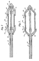
- a balloon 14 is fixed to the distal end of the catheter by adhesive attachment of the proximal end to the outer shaft 16 of the catheter and the distal end to the inner shaft 18 of the catheter. Other arrangements known in the art may be used.
- Balloon 14 is shown in Figure 1 in its contracted state and in Figure 2 in its expanded state.
- a stent 20 is fixed about balloon 14 by two overlying retaining sleeves 22 and 24.
- the stent may be a self-expanding stent which upon release self-expands and is further expanded or is merely aided in release by balloon expansion from the sleeves.
- Such stents may self-expand elastically or may be thermally induced such as stents formed of Nitinol or other shape memory metals or materials.
- Any kind of stent may be delivered by the system of the invention, including plastically deformable or elastically deformable and they may be of any configuration or structure so long as they can be loaded at a low diameter and deployed at a larger diameter, i.e., have a contracted condition and being expandable to an expanded condition of large diameter.
- Stent 20 may be any of the various types known in the art, either balloon expandable or self-expandable. Exemplary stents are shown in U.S. Patent No. 4,735,665; U.S. Patent No. 4,950,227; EPO application No. 707 837 A1, and U.S. Patent No. 5,445,646. All of these patents are intended to be exemplary only and not limiting. Various materials including stainless steel, tantalum, shape memory alloys and plastic may be used.
- Stent 20 is radially compressed, as by crimping to a contracted condition, against balloon 14 to a relatively small loaded diameter having an OD of 0.11 cm (.044 inches) for example, although it has a larger released diameter in the expanded condition.
- Sleeves 22 and 24 may be formed of polyurethane tubing or the like, having for example an ID of 0.081-0.097 cm [.032-.038 inches] and a wall thickness of 0.005-0.010 cm [.002-.004 inches], for example, and are axially fixed along catheter 10 to the proximal end of balloon 14 at 26 and to the distal end of balloon 14 at 27 by means of polyurethane adhesive.
- the distal end also includes a tapered end 28 which may be formed of the same adhesive.
- the sleeves may be of an expandable material, preferably elastomers such as polyurethane, silicone, latex or polyether amide, by way of example only.
- the material should be formable into a thin walled tube.
- Only one sleeve may be provided at one end of the stent, preferably the distal end. However, the use of a pair of sleeves, one at each end of the stent, is most preferred.
- Sleeves 22 and 24 overlap stent 20 at each of its ends 30 and 32, respectively.
- the overlap may be 0.5-1.5 mm.
- Reinforcing rings 34 are included under the overlapping portions of sleeves 22 and 24 and in contact with the stent ends.
- the rings may be attached to the sleeves with adhesive such as a polyurethane adhesive.
- the rings may be plastic, such as polyimide or polyethylene, or metal, such as platinum, gold, stainless steel or Nitinol, and may be 0.003-0.010 cm [.001-.004 inches] and the ID of the ring is to match the desired OD of the stent.
- the function of the rings is to compress the stent and hold it down.
- balloon 14 in its expanded state balloon 14 has an enlarged diameter with tapered portions 36 and 38 at each end thereof.
- Stent 20 is released from sleeves 22 and 24 upon expansion of balloon 14 by pulling out of the sleeves and the bunching back of the sleeves.
- the stent deploys.
- the sleeves contract about balloon 14 when it is deflated. Deflation allows balloon 14 and sleeves 22 and 24 along with catheter 10 to be axially removed from the body.
- the fit between the sleeve ID and the balloon end portion tends to be so large as to create difficulty in forming an acceptable profile for the catheter and it is difficult to sufficiently increase the OD of the balloon catheter to provide adequate interference fit of the stcnt to the balloon.
- the rings provide increased friction fit in such instances and aid in controlling spring-back of the crimped stent.
- polyurethane sleeves In assembling the polyurethane sleeves, they can be temporarily swelled by exposure to a solvent such as toluene, alcohol, or others as known in the art, then pushed on the ends of the stent. The sleeves are then bonded to the balloon ends with a polyurethane adhesive or the like.
- a solvent such as toluene, alcohol, or others as known in the art
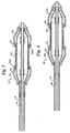
- the rings 34 seen in Figures 1 and 2 may take the form of wire coils 34a which may for example be stainless steel or Nitinol or polyamides such as nylon.
- the sleeves 22 and 24 of the preceding Figures may take the form of spiral coils of plastic 22a and 24a such as polyamide or polyethylene or polyimide for example.
- the spiral may be cut only partially into the body as a spiral cut or it may be cut all the way through as shown.
- the sleeves 22 and 24 of the preceding Figures may be replaced by metal such as stainless steel or Nitinol coils 22b (not shown) and 24b, for example.
- Figure 5 shows such coils engaging stent 20 in the loaded or crimped position, ready for delivery.
- Figure 6 shows the coils retracted by balloon expansion with stent 20 partially expanded and ready to be deployed.
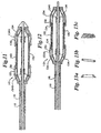
- metal coils 22b (not shown) and 24b of Figures 5 and 6 may take the form of flat coiled ribbons 22c and 24c in either metal or plastic of the types already described.
- the coiled ribbons 22c and 24c are shown engaging the stent 20 in the loaded or crimped position, ready for delivery.
- Figure 8 shows them retracted by balloon expansion with stent 20 partially expanded ready for deployment.
- Any body compatible metal and plastic having the requisite strength characteristics, and/or other physical characteristics may be used in the various embodiments of this invention.
- a stent delivery system 110 includes a catheter such as an over-the-wire or rapid exchange. Shown is a catheter 110 having a outer shaft 116, a guidewire lumen 118 with marker band secured thereto 115 and a distal tip 117. As above, balloon 114 is fixed to the distal end of the catheter by adhesive attachment of the proximal end to the outer shaft 116 of the catheter and the distal end to the inner shaft 118 of the catheter. Other arrangements known in the art may be used.
- Balloon 114 is shown in Figure 9 in its contracted state and in Figure 10 in its expanded state.
- a stent 120 is fixed about balloon 114 by two overlying retaining sleeves, or socks, 122 and 124, which cover the ends 130, 132 of the stent, respectively.
- stents may be used with balloon expansion, as described above.
- Stent 120 is radially compressed, as by crimping to a contracted condition, against balloon 114 to a relatively small loaded diameter having an OD of 0.11 cm (.044 inches) for example, although it has a larger released diameter in the expanded condition.
- sleeves 122 and 124 may be formed of polyurethane tubing or the like, having for example an ID of 0.081-0.097 cm [.032-.038 inches] and a wall thickness of 0.005-0.010 cm [.002-.004 inches], for example, and are axially fixed along catheter 110 to the proximal end of balloon 114 at 126 and to the distal end of balloon 114 at 127 by means of polyurethane adhesive 126, 127.
- the sleeves may be of an expandable material, preferable elastomers such as polyurethane, silicone, latex or polyether amide, by way of example only, most preferably polyurethane or polyolefin copolymer (POC); SurlynTM.
- POC polyolefin copolymer
- SurlynTM SurlynTM.
- the material should be formable into a thin walled tube. Only one sleeve may be provided at one end of the stent, preferably the proximal end. However, the use of a pair of sleeves, one at each end of the stent, is most preferred.
- Sleeves 122 and 124 overlap stent 120 at each of its ends 130 and 132, respectively.
- the overlap may be .5-1.5 mm.
- Rings 134 are included under, and preferably adhered to, the sleeves 122 and 124 positioned on the cone portion of the balloon 114, preferably the upper portion, when the balloon is in its collapsed configuration.
- the rings may be attached to the sleeves with adhesive such as a polyurethane adhesive.
- the rings may be rigid or any material which effectively retains its substantially annular shape, preferably non-elastomeric material, including plastic, such as polyimide or polyethylene, or metal, such as platinum, gold, stainless steel or Nitinol, and may be .25-.5 mm in length and the ID of the ring is to match the desired OD of the upper portion of the cone portion.
- the sleeve material may be of a higher Durometer urethane or even merely may have a thicker annular region in the sleeve to function as a ring. The function of the rings is to more effectively and smoothly draw the sleeve off of the ends of the stent, by creating a more axial force on the ring 134.
- balloon 114 in its expanded state balloon 114 has an enlarged diameter with tapered cone portions 136 and 138 at each end thereof.
- Stent 120 is released from sleeves 122 and 124 upon expansion of balloon 114 due to the axial force created by the ring which draws the sleeves gradually outward, bunching the sleeve between the rings 134 and the fixed position of the sleeve on the catheter.
- a combination of radial and axial forces are applied to the ring 134. Since the rings resist the radial force, they are driven primarily axially, dragging the sleeve off of the ends of the stent and balloon.
- the increased axial pressure allows for a more controlled and steady release of the stent and balloon, as opposed to a sudden release which may happen when the primary force on the ring is in the radial direction.
- the stent deploys.
- the sleeves contract about balloon 114 when it is deflated. Deflation allows balloon 114 and sleeves 122 and 124 along with catheter 110 to be axially removed from the body.
- the positioning of the rings 134 which provides for greater axial force, allow the sleeves to be made of softer and thinner material, such as softer grades of urethanes, which include the use of lower Durometer urethane such as 65-95A or 55D (55D Durometer urethane), for example Tecothane 1055D.
- the polyurethane sleeves In assembling the polyurethane sleeves, they can be temporarily swelled by exposure to a solvent such as toluene, alcohol, or others as known in the art, then pushed on the ends of the stent. The sleeves are then bonded to the balloon ends with a polyurethane adhesive or the like. The rings are either held in place by the tension between the sleeves and balloon or the rings are attached to the sleeves.
- a solvent such as toluene, alcohol, or others as known in the art
- rings 134a seen in Figures 9 and 10 may take the form of wire coils 134a which may for example be stainless steel or Nitinol or polyamides such as nylon.
- the sleeves 122 and 124 of the preceding Figures may take the form of spiral coils of plastic 122a and 124a such as polyamide or polyethylene or polyimide for example.
- the spiral may be cut only partially into the body as a spiral cut or it may be cut all the way through as shown.
- the rings 134 are preferably circular in shape, but may also be any regular polygon.
- Figure 13a-c illustrate possible designs of the rings 134.
- the ring of Figure 13a has a tapered profile to conform to the cones' tapered profiles.
- Figure 13b illustrates a typical tubular ring and
- Figure 13c illustrates a coil ring.
- Any body compatible metal and plastic having the requisite strength characteristics, and/or other physical characteristics may be used in the various embodiments of this invention.
Abstract
Description
Claims (19)
- A stent delivery system (10) comprising:a catheter comprising an expandable distal portion constructed and arranged for expanding the outer diameter of said catheter from a contracted state to an expanded state;a stent (20) positioned around said distal portion of said catheter, said stent having a contracted condition and being expandable to an expanded condition, and being sized in said contracted condition to closely surround said catheter in the contracted state, said stent having at least an end portion lying over said expandable portion of said catheter;end covering means in the region of said distal portion of said catheter and positioned around said catheter, having a first end fixed to said catheter, and a second end lying over said end portion of said stent; andsaid end covering means retaining said end of said stent (20) on said catheter when said catheter is in the contracted state, said catheter and stent cooperatively constructed and arranged for expansion of said catheter from said contracted state to said expanded state and to cause said end covering means to slide relatively axially, drawing said end covering means from said stent, thereby releasing said end (30) of the stent from said catheter;said end covering means comprising a sleeve (20, 24) and at least one ring (34), wherein the at least one ring is associated with the sleeve or said end covering means comprising a coil (22a, 24a; 22b, 24b; 22c, 24c) in the region of said distal portion of said catheter and at least one ring, wherein the at least one ring is associated with the coil, the coil being positioned around said catheter.
- The stent delivery system of claim 1, wherein said ring (34) is attached to said sleeve.
- The stent delivery system of claim 2, wherein said ring (34) is attached to the second end of said sleeve.
- The stent delivery system of claim 1, wherein said ring being a substantially rigid annular portion integral with the sleeve material.
- The stent delivery system of claim 4, wherein the rigid annular portion has an increased rigidity relative to the remainder of the sleeve.
- The stent delivery system of claim 5, wherein the rigid annular portion of the at least one sleeve overlies the first stent end when the stent is in the contracted state.
- The stent delivery system of claim 6, wherein the at least one sleeve comprises a first sleeve and a second sleeve opposingly positioned, the first sleeve overlying the first stent end and the second sleeve overlying the second stent end.
- The stent delivery system of claim 7, wherein the annular region of increased thickness of the first sleeve and the second sleeve overly the first stent end and the second stent end, respectively, when the stent is in the contracted state.
- The stent delivery system according to one of the preceding claims, wherein the sleeve is positioned between the stent and the expandable portion of the catheter.
- The stent delivery system of one of the claims 1 to 9, wherein said sleeve being formed from polyurethane or from any elastomer able to be expanded with a balloon angioplasty catheter, and formable into a thin-walled tube in the shape of a cylinder.
- The stent delivery system of one of the claims 1 to 10, wherein said sleeve fixes said stent at the distal end of said stent or covers the proximal end of said stent.
- The stent delivery system of one of the claims 1 to 11, wherein said ring being formed in the shape of a coil.
- The stent delivery system of claim 12, wherein said ring in the shape of a coil is made from plastic or metal.
- The stent delivery system of claim 1 or 13, wherein said coil is rounded in cross-section.
- The stent delivery system of claim 13, wherein said coil is ribbon-like in cross-section.
- The stent delivery system of claim 13 to 15, wherein there are two coils, opposingly positioned, in the region of said distal portion of said catheter and positioned around said catheter, having respective first ends fixed to said catheter, and respective second ends defining a margin lying over said end portion of said stent.
- The stent delivery system of one of the claims 1 to 16, wherein said stent having a first and a second end portion lying over said expandable portion of said catheter, the delivery system comprising:a first and a second sleeve in the region of said distal portion of said catheter and positioned around said catheter, each having a first end fixed to said catheter, and a second end lying over said first and second ends of said stent, anda first and a second ring, each being respectively attached to said first and second sleeves and positioned around said ends of said stent.
- The stent delivery system of one of the claims 1 to 17, wherein said expandable distal portion comprises a balloon (14) mounted on a shaft of the catheter, whereby said stent is expanded by the expansion of said balloon.
- The stent delivery system of claim 18, wherein said balloon having at least one cone portion mounted on a shaft of the catheter and wherein the ring is positioned between the cone portion and the sleeve when the balloon is in its contracted state.
Applications Claiming Priority (3)
| Application Number | Priority Date | Filing Date | Title |
|---|---|---|---|
| US702149 | 1985-02-15 | ||
| US08/702,149 US5980530A (en) | 1996-08-23 | 1996-08-23 | Stent delivery system |
| PCT/US1997/014141 WO1998007388A1 (en) | 1996-08-23 | 1997-08-22 | Stent delivery system |
Publications (2)
| Publication Number | Publication Date |
|---|---|
| EP0932376A1 EP0932376A1 (en) | 1999-08-04 |
| EP0932376B1 true EP0932376B1 (en) | 2003-01-02 |
Family
ID=24820045
Family Applications (1)
| Application Number | Title | Priority Date | Filing Date |
|---|---|---|---|
| EP97938245A Expired - Lifetime EP0932376B1 (en) | 1996-08-23 | 1997-08-22 | Stent delivery system |
Country Status (6)
| Country | Link |
|---|---|
| US (4) | US5980530A (en) |
| EP (1) | EP0932376B1 (en) |
| AT (1) | ATE230244T1 (en) |
| AU (1) | AU4062297A (en) |
| DE (1) | DE69718192T2 (en) |
| WO (1) | WO1998007388A1 (en) |
Cited By (1)
| Publication number | Priority date | Publication date | Assignee | Title |
|---|---|---|---|---|
| US7654264B2 (en) | 2006-07-18 | 2010-02-02 | Nellcor Puritan Bennett Llc | Medical tube including an inflatable cuff having a notched collar |
Families Citing this family (206)
| Publication number | Priority date | Publication date | Assignee | Title |
|---|---|---|---|---|
| US5749848A (en) * | 1995-11-13 | 1998-05-12 | Cardiovascular Imaging Systems, Inc. | Catheter system having imaging, balloon angioplasty, and stent deployment capabilities, and method of use for guided stent deployment |
| US6077273A (en) | 1996-08-23 | 2000-06-20 | Scimed Life Systems, Inc. | Catheter support for stent delivery |
| US5968069A (en) | 1996-08-23 | 1999-10-19 | Scimed Life Systems, Inc. | Stent delivery system having stent securement apparatus |
| US6432127B1 (en) | 1996-10-11 | 2002-08-13 | Transvascular, Inc. | Devices for forming and/or maintaining connections between adjacent anatomical conduits |
| AUPO700897A0 (en) * | 1997-05-26 | 1997-06-19 | William A Cook Australia Pty Ltd | A method and means of deploying a graft |
| US6168616B1 (en) | 1997-06-02 | 2001-01-02 | Global Vascular Concepts | Manually expandable stent |
| CA2244639A1 (en) * | 1997-08-11 | 1999-02-11 | Advanced Cardiovascular Systems, Inc. | Retainer for a stent-carrying balloon catheter |
| US6330884B1 (en) | 1997-11-14 | 2001-12-18 | Transvascular, Inc. | Deformable scaffolding multicellular stent |
| CA2283827C (en) * | 1998-01-14 | 2009-02-03 | Sumitomo Bakelite Co., Ltd | Balloon catheter for puncturing, medical tube introducing device using the catheter and method for use thereof |
| DE69931472T2 (en) * | 1998-03-04 | 2006-09-28 | Boston Scientific Ltd., St. Michael | STENT WITH IMPROVED CELL CONFIGURATION |
| DE19840701A1 (en) * | 1998-08-21 | 2000-02-24 | Biotronik Mess & Therapieg | Balloon catheter |
| US6196230B1 (en) | 1998-09-10 | 2001-03-06 | Percardia, Inc. | Stent delivery system and method of use |
| US6261304B1 (en) | 1998-09-10 | 2001-07-17 | Percardia, Inc. | Delivery methods for left ventricular conduit |
| EP1112041A1 (en) | 1998-09-10 | 2001-07-04 | Percardia, Inc. | Tmr shunt |
| AU6384699A (en) | 1998-09-10 | 2000-04-03 | Percardia, Inc. | Tmr shunt |
| EP1126795A2 (en) * | 1998-11-06 | 2001-08-29 | St. Jude Medical Cardiovascular Group, Inc. | Medical graft connector component and methods of making and installing same |
| US6942654B1 (en) * | 2000-01-19 | 2005-09-13 | Scimed Life Systems, Inc. | Intravascular catheter with axial member |
| US6183505B1 (en) * | 1999-03-11 | 2001-02-06 | Medtronic Ave, Inc. | Method of stent retention to a delivery catheter balloon-braided retainers |
| US6443980B1 (en) | 1999-03-22 | 2002-09-03 | Scimed Life Systems, Inc. | End sleeve coating for stent delivery |
| US6221097B1 (en) * | 1999-03-22 | 2001-04-24 | Scimed Life System, Inc. | Lubricated sleeve material for stent delivery |
| US6325825B1 (en) * | 1999-04-08 | 2001-12-04 | Cordis Corporation | Stent with variable wall thickness |
| US6270521B1 (en) * | 1999-05-21 | 2001-08-07 | Cordis Corporation | Stent delivery catheter system for primary stenting |
| US6168617B1 (en) | 1999-06-14 | 2001-01-02 | Scimed Life Systems, Inc. | Stent delivery system |
| US6280412B1 (en) * | 1999-06-17 | 2001-08-28 | Scimed Life Systems, Inc. | Stent securement by balloon modification |
| US6302892B1 (en) | 1999-08-04 | 2001-10-16 | Percardia, Inc. | Blood flow conduit delivery system and method of use |
| US6638237B1 (en) | 1999-08-04 | 2003-10-28 | Percardia, Inc. | Left ventricular conduits and methods for delivery |
| US6533806B1 (en) * | 1999-10-01 | 2003-03-18 | Scimed Life Systems, Inc. | Balloon yielded delivery system and endovascular graft design for easy deployment |
| US6602263B1 (en) * | 1999-11-30 | 2003-08-05 | St. Jude Medical Atg, Inc. | Medical grafting methods and apparatus |
| US6994687B1 (en) * | 2000-01-19 | 2006-02-07 | Cordis Neurovascular, Inc. | Inflatable balloon catheter with purge mechanism and method |
| US6723113B1 (en) * | 2000-01-19 | 2004-04-20 | Cordis Neurovascular, Inc. | Inflatable balloon catheter seal and method |
| US6562061B1 (en) | 2000-02-22 | 2003-05-13 | Scimed Life Systems, Inc. | Stent delivery balloon with securement structure |
| US6264683B1 (en) | 2000-03-17 | 2001-07-24 | Advanced Cardiovascular Systems, Inc. | Stent delivery catheter with bumpers for improved retention of balloon expandable stents |
| US6315708B1 (en) * | 2000-03-31 | 2001-11-13 | Cordis Corporation | Stent with self-expanding end sections |
| US6585747B1 (en) * | 2000-04-14 | 2003-07-01 | Advanced Cardiovascular Systems, Inc. | Interdigitating polymeric endcap for enhanced stent retention |
| US6964676B1 (en) | 2000-04-14 | 2005-11-15 | Scimed Life Systems, Inc. | Stent securement system |
| US6387118B1 (en) * | 2000-04-20 | 2002-05-14 | Scimed Life Systems, Inc. | Non-crimped stent delivery system |
| US6520984B1 (en) * | 2000-04-28 | 2003-02-18 | Cardiovasc, Inc. | Stent graft assembly and method |
| US20030114918A1 (en) | 2000-04-28 | 2003-06-19 | Garrison Michi E. | Stent graft assembly and method |
| US6854467B2 (en) | 2000-05-04 | 2005-02-15 | Percardia, Inc. | Methods and devices for delivering a ventricular stent |
| US7001395B2 (en) * | 2000-06-08 | 2006-02-21 | Hajianpour Mohammed A | Medullary plug including an external shield and an internal valve |
| SE522805C2 (en) | 2000-06-22 | 2004-03-09 | Jan Otto Solem | Stent Application System |
| US20020016597A1 (en) * | 2000-08-02 | 2002-02-07 | Dwyer Clifford J. | Delivery apparatus for a self-expanding stent |
| US6743219B1 (en) | 2000-08-02 | 2004-06-01 | Cordis Corporation | Delivery apparatus for a self-expanding stent |
| US6860960B1 (en) * | 2000-09-05 | 2005-03-01 | Scimed Life Systems, Inc. | Method of applying a laser beam around the circumference of a catheter |
| US6676497B1 (en) * | 2000-09-08 | 2004-01-13 | Applied Materials Inc. | Vibration damping in a chemical mechanical polishing system |
| US6565595B1 (en) | 2000-09-18 | 2003-05-20 | Scimed Life Systems, Inc. | Two component sleeves |
| US6607552B1 (en) * | 2000-09-18 | 2003-08-19 | Scimed Life Systems, Inc. | Rolling socks |
| US6554841B1 (en) * | 2000-09-22 | 2003-04-29 | Scimed Life Systems, Inc. | Striped sleeve for stent delivery |
| US6733520B2 (en) | 2000-09-22 | 2004-05-11 | Scimed Life Systems, Inc. | Sandwich striped sleeve for stent delivery |
| US20030065376A1 (en) * | 2001-10-02 | 2003-04-03 | Jan Seppala | Stent body sock |
| WO2002028319A2 (en) * | 2000-10-05 | 2002-04-11 | Boston Scientific Limited | Stent delivery system with membrane |
| JP2004512867A (en) | 2000-10-05 | 2004-04-30 | ボストン サイエンティフィック リミテッド | Body socks for stent delivery catheters |
| DE60115269T2 (en) | 2000-10-06 | 2006-06-01 | Boston Scientific Ltd., St Michael | ATTACHING A HOLDING SLEEVE TO A CATHETER BY WELDING |
| US6461326B1 (en) | 2000-10-26 | 2002-10-08 | Scimed Life Systems, Inc. | Fluorescent dyed adhesive for bonding various components in a medical device |
| US6656211B1 (en) * | 2000-10-26 | 2003-12-02 | Scimed Life Systems, Inc. | Stent delivery system with improved tracking |
| WO2002039929A2 (en) * | 2000-11-20 | 2002-05-23 | Scimed Life Systems, Inc. | Stent retaining hybrid sleeve material and structure |
| US7115137B2 (en) * | 2000-12-12 | 2006-10-03 | Advanced Cardiovascular Systems, Inc. | Balloon catheter having a balloon distal skirt section with a reduced outer diameter secured to a soft distal tip member |
| US6599267B1 (en) * | 2000-12-22 | 2003-07-29 | Advanced Cardiovascular Systems, Inc. | Transluminal injection device for intravascular drug delivery |
| IL140870A0 (en) * | 2001-01-11 | 2002-02-10 | Mind Guard Ltd | Deployment system for implantable self-expandable intraluminal devices |
| WO2002067653A2 (en) | 2001-02-26 | 2002-09-06 | Scimed Life Systems, Inc. | Bifurcated stent and delivery system |
| US6589274B2 (en) * | 2001-03-23 | 2003-07-08 | Medtronic Ave, Inc. | Stent delivery catheter and method of making same |
| US7556646B2 (en) * | 2001-09-13 | 2009-07-07 | Edwards Lifesciences Corporation | Methods and apparatuses for deploying minimally-invasive heart valves |
| US6623451B2 (en) * | 2001-05-01 | 2003-09-23 | Scimed Life Systems, Inc. | Folding spring for a catheter balloon |
| AU2002342613A1 (en) * | 2001-05-09 | 2002-11-25 | Geron Corporation | Treatment for wounds |
| US6695920B1 (en) | 2001-06-27 | 2004-02-24 | Advanced Cardiovascular Systems, Inc. | Mandrel for supporting a stent and a method of using the mandrel to coat a stent |
| US6726714B2 (en) * | 2001-08-09 | 2004-04-27 | Scimed Life Systems, Inc. | Stent delivery system |
| US7004963B2 (en) | 2001-09-14 | 2006-02-28 | Scimed Life Systems, Inc. | Conformable balloons |
| US6863683B2 (en) | 2001-09-19 | 2005-03-08 | Abbott Laboratoris Vascular Entities Limited | Cold-molding process for loading a stent onto a stent delivery system |
| US20100016943A1 (en) | 2001-12-20 | 2010-01-21 | Trivascular2, Inc. | Method of delivering advanced endovascular graft |
| CA2470824A1 (en) * | 2001-12-21 | 2003-08-28 | Cardiovasc, Inc. | Composite stent with polymeric covering and bioactive coating |
| US20030135256A1 (en) * | 2002-01-14 | 2003-07-17 | Gallagher Brendan P. | Stent delivery system |
| US7785340B2 (en) * | 2002-02-04 | 2010-08-31 | Boston Scientific Scimed, Inc. | Bonding sleeve for medical device |
| US7887573B2 (en) * | 2002-02-22 | 2011-02-15 | Boston Scientific Scimed, Inc. | Method and apparatus for deployment of an endoluminal device |
| US7004964B2 (en) * | 2002-02-22 | 2006-02-28 | Scimed Life Systems, Inc. | Apparatus and method for deployment of an endoluminal device |
| US6866679B2 (en) | 2002-03-12 | 2005-03-15 | Ev3 Inc. | Everting stent and stent delivery system |
| US6830575B2 (en) * | 2002-05-08 | 2004-12-14 | Scimed Life Systems, Inc. | Method and device for providing full protection to a stent |
| US6858083B2 (en) * | 2002-06-05 | 2005-02-22 | Scimed Lifesystems, Inc. | Apparatus and method for closed-loop control of RF generator for welding polymeric catheter components |
| US8518096B2 (en) * | 2002-09-03 | 2013-08-27 | Lifeshield Sciences Llc | Elephant trunk thoracic endograft and delivery system |
| US6953470B2 (en) * | 2002-09-11 | 2005-10-11 | Boston Scientific Scimed, Inc. | Catheter support |
| US7226472B2 (en) * | 2002-10-15 | 2007-06-05 | Boston Scientific Scimed, Inc. | Catheter balloon with advantageous cone design |
| WO2004039289A1 (en) * | 2002-10-31 | 2004-05-13 | Ecole De Technologie Superieure | Balloon deployable stent and method of using the same |
| US7189215B2 (en) * | 2002-11-12 | 2007-03-13 | Medtronic Vascular, Inc. | Catheter with full-length core wire shaft for core wire interchangeability |
| US20040092868A1 (en) * | 2002-11-12 | 2004-05-13 | Medtronic Ave, Inc. | Catheter with full-length core wire shaft for core wire interchangeability |
| US7074276B1 (en) | 2002-12-12 | 2006-07-11 | Advanced Cardiovascular Systems, Inc. | Clamp mandrel fixture and a method of using the same to minimize coating defects |
| US20040181186A1 (en) * | 2003-03-13 | 2004-09-16 | Scimed Life Systems, Inc. | Medical device |
| US20050209672A1 (en) * | 2004-03-02 | 2005-09-22 | Cardiomind, Inc. | Sliding restraint stent delivery systems |
| US8016869B2 (en) | 2003-03-26 | 2011-09-13 | Biosensors International Group, Ltd. | Guidewire-less stent delivery methods |
| ES2346059T3 (en) | 2003-03-26 | 2010-10-08 | Biosensors International Group Ltd. | IMPLANT SUPPLY CATHETER WITH ELECTROLYTICALLY EROSIONABLE JOINTS. |
| US7771463B2 (en) | 2003-03-26 | 2010-08-10 | Ton Dai T | Twist-down implant delivery technologies |
| US20040215314A1 (en) * | 2003-04-25 | 2004-10-28 | Kantor John D. | Stent deployment assembly with collars for drug-eluting stent |
| US7235093B2 (en) * | 2003-05-20 | 2007-06-26 | Boston Scientific Scimed, Inc. | Mechanism to improve stent securement |
| US20050049668A1 (en) * | 2003-08-29 | 2005-03-03 | Jones Donald K. | Self-expanding stent and stent delivery system for treatment of vascular stenosis |
| US7198675B2 (en) | 2003-09-30 | 2007-04-03 | Advanced Cardiovascular Systems | Stent mandrel fixture and method for selectively coating surfaces of a stent |
| US7162030B2 (en) * | 2003-12-23 | 2007-01-09 | Nokia Corporation | Communication device with rotating housing |
| US7887574B2 (en) * | 2003-12-23 | 2011-02-15 | Scimed Life Systems, Inc. | Stent delivery catheter |
| US7468070B2 (en) | 2004-01-23 | 2008-12-23 | Boston Scientific Scimed, Inc. | Stent delivery catheter |
| US7651521B2 (en) | 2004-03-02 | 2010-01-26 | Cardiomind, Inc. | Corewire actuated delivery system with fixed distal stent-carrying extension |
| US20060206200A1 (en) | 2004-05-25 | 2006-09-14 | Chestnut Medical Technologies, Inc. | Flexible vascular occluding device |
| US8628564B2 (en) | 2004-05-25 | 2014-01-14 | Covidien Lp | Methods and apparatus for luminal stenting |
| US8267985B2 (en) | 2005-05-25 | 2012-09-18 | Tyco Healthcare Group Lp | System and method for delivering and deploying an occluding device within a vessel |
| US8617234B2 (en) | 2004-05-25 | 2013-12-31 | Covidien Lp | Flexible vascular occluding device |
| JP2008502378A (en) | 2004-05-25 | 2008-01-31 | チェストナット メディカル テクノロジーズ インコーポレイテッド | Flexible vascular closure device |
| WO2010120926A1 (en) | 2004-05-25 | 2010-10-21 | Chestnut Medical Technologies, Inc. | Vascular stenting for aneurysms |
| US7284363B2 (en) * | 2004-06-16 | 2007-10-23 | Honeywell International, Inc. | Method of power generation for airborne vehicles |
| US8500785B2 (en) | 2004-07-13 | 2013-08-06 | Boston Scientific Scimed, Inc. | Catheter |
| US7765670B2 (en) * | 2004-08-13 | 2010-08-03 | Boston Scientific Scimed, Inc. | Method to simultaneously load and cover self expanding stents |
| US7658757B2 (en) * | 2004-10-08 | 2010-02-09 | Boston Scientific Scimed, Inc. | Endoprosthesis delivery system |
| US7820937B2 (en) * | 2004-10-27 | 2010-10-26 | Boston Scientific Scimed, Inc. | Method of applying one or more electromagnetic beams to form a fusion bond on a workpiece such as a medical device |
| US8202245B2 (en) * | 2005-01-26 | 2012-06-19 | Boston Scientific Scimed, Inc. | Medical devices and methods of making the same |
| US7914569B2 (en) | 2005-05-13 | 2011-03-29 | Medtronics Corevalve Llc | Heart valve prosthesis and methods of manufacture and use |
| US9034025B2 (en) | 2005-05-23 | 2015-05-19 | Ostial Corporation | Balloon catheters and methods for use |
| US8273101B2 (en) | 2005-05-25 | 2012-09-25 | Tyco Healthcare Group Lp | System and method for delivering and deploying an occluding device within a vessel |
| AU2005332044B2 (en) * | 2005-05-25 | 2012-01-19 | Covidien Lp | System and method for delivering and deploying and occluding device within a vessel |
| AU2012201929B2 (en) * | 2005-05-25 | 2013-03-28 | Covidien Lp | System and method for delivering and deploying an occluding device within a vessel |
| US20070073379A1 (en) * | 2005-09-29 | 2007-03-29 | Chang Jean C | Stent delivery system |
| US7823533B2 (en) | 2005-06-30 | 2010-11-02 | Advanced Cardiovascular Systems, Inc. | Stent fixture and method for reducing coating defects |
| JP2009501567A (en) | 2005-07-14 | 2009-01-22 | カペラ・インコーポレイテッド | Supply system and method for use in deployment of self-expanding intravascular devices |
| US7735449B1 (en) | 2005-07-28 | 2010-06-15 | Advanced Cardiovascular Systems, Inc. | Stent fixture having rounded support structures and method for use thereof |
| WO2007022496A2 (en) * | 2005-08-19 | 2007-02-22 | Icon Medical Corp. | Medical device deployment instrument |
| US7582111B2 (en) * | 2005-08-22 | 2009-09-01 | Incept, Llc | Steep-taper flared stents and apparatus and methods for delivering them |
| US20070100414A1 (en) | 2005-11-02 | 2007-05-03 | Cardiomind, Inc. | Indirect-release electrolytic implant delivery systems |
| US20070123994A1 (en) * | 2005-11-29 | 2007-05-31 | Ethicon Endo-Surgery, Inc. | Internally Placed Gastric Restriction Device |
| US7867547B2 (en) | 2005-12-19 | 2011-01-11 | Advanced Cardiovascular Systems, Inc. | Selectively coating luminal surfaces of stents |
| WO2007100556A1 (en) | 2006-02-22 | 2007-09-07 | Ev3 Inc. | Embolic protection systems having radiopaque filter mesh |
| US8092508B2 (en) * | 2006-03-30 | 2012-01-10 | Stryker Corporation | Implantable medical endoprosthesis delivery system |
| US8003156B2 (en) | 2006-05-04 | 2011-08-23 | Advanced Cardiovascular Systems, Inc. | Rotatable support elements for stents |
| US7985441B1 (en) | 2006-05-04 | 2011-07-26 | Yiwen Tang | Purification of polymers for coating applications |
| US8241246B2 (en) * | 2006-05-22 | 2012-08-14 | Abbott Laboratories Vascular Enterprises Ltd. | Side by side lumen catheter and method of manufacture thereof |
| US8333000B2 (en) | 2006-06-19 | 2012-12-18 | Advanced Cardiovascular Systems, Inc. | Methods for improving stent retention on a balloon catheter |
| US20080009799A1 (en) * | 2006-06-30 | 2008-01-10 | Lap Reinder N | Resilient protection sleeve for balloon catheter |
| JP5319546B2 (en) * | 2006-12-15 | 2013-10-16 | カーディオマインド, インコーポレイテッド | Stent system |
| US8323307B2 (en) | 2007-02-13 | 2012-12-04 | Cook Medical Technologies Llc | Balloon catheter with dilating elements |
| US20080228257A1 (en) * | 2007-03-15 | 2008-09-18 | Jacob Richter | Covered stent balloon and method of using same |
| US7776080B2 (en) * | 2007-04-25 | 2010-08-17 | Abbott Cardiovascualr Systems Inc. | Stent delivery catheter system and method of implanting a self-expanding stent with embolic protection |
| JP5667873B2 (en) * | 2007-06-21 | 2015-02-12 | カペラ・インコーポレイテッド | Medical device delivery system with sheath having balloon relative position |
| US20090112159A1 (en) * | 2007-10-31 | 2009-04-30 | David Slattery | Delivery System With Profiled Sheath Having Balloon-Oriented Position |
| US20080319388A1 (en) * | 2007-06-21 | 2008-12-25 | David Slattery | Device delivery system with balloon-relative sheath positioning |
| US8092510B2 (en) * | 2007-07-25 | 2012-01-10 | Cook Medical Technologies Llc | Retention wire for self-expanding stent |
| US8333795B2 (en) | 2007-08-27 | 2012-12-18 | Boston Scientific Scimed, Inc. | Bulging balloon for bifurcation catheter assembly and methods |
| US20090069878A1 (en) * | 2007-08-27 | 2009-03-12 | Boston Scientific Scimed, Inc. | Bifurcation post-dilatation balloon and methods |
| US8663309B2 (en) | 2007-09-26 | 2014-03-04 | Trivascular, Inc. | Asymmetric stent apparatus and method |
| US8066755B2 (en) | 2007-09-26 | 2011-11-29 | Trivascular, Inc. | System and method of pivoted stent deployment |
| CN101917929A (en) | 2007-10-04 | 2010-12-15 | 特里瓦斯库拉尔公司 | Modular vascular graft for low profile percutaneous delivery |
| US7981151B2 (en) * | 2007-10-15 | 2011-07-19 | Edwards Lifesciences Corporation | Transcatheter heart valve with micro-anchors |
| US8328861B2 (en) | 2007-11-16 | 2012-12-11 | Trivascular, Inc. | Delivery system and method for bifurcated graft |
| US8083789B2 (en) | 2007-11-16 | 2011-12-27 | Trivascular, Inc. | Securement assembly and method for expandable endovascular device |
| US8236039B2 (en) * | 2007-12-21 | 2012-08-07 | Abbott Laboratories | Vena cava filter having wall contacts |
| EP2240121B1 (en) * | 2008-01-16 | 2019-05-22 | St. Jude Medical, Inc. | Delivery and retrieval systems for collapsible/expandable prosthetic heart valves |
| JP5687070B2 (en) * | 2008-01-24 | 2015-03-18 | メドトロニック,インコーポレイテッド | Stent for prosthetic heart valve |
| US8157852B2 (en) | 2008-01-24 | 2012-04-17 | Medtronic, Inc. | Delivery systems and methods of implantation for prosthetic heart valves |
| US20090287290A1 (en) * | 2008-01-24 | 2009-11-19 | Medtronic, Inc. | Delivery Systems and Methods of Implantation for Prosthetic Heart Valves |
| US9149358B2 (en) * | 2008-01-24 | 2015-10-06 | Medtronic, Inc. | Delivery systems for prosthetic heart valves |
| US9675482B2 (en) | 2008-05-13 | 2017-06-13 | Covidien Lp | Braid implant delivery systems |
| US8715331B2 (en) | 2008-08-06 | 2014-05-06 | Boston Scientific Scimed, Inc. | Stent edge protection and methods |
| EP2668934B1 (en) | 2008-12-12 | 2017-05-10 | Abbott Laboratories Vascular Enterprises Limited | Process for loading a stent onto a stent delivery system |
| US8886636B2 (en) * | 2008-12-23 | 2014-11-11 | Yahoo! Inc. | Context transfer in search advertising |
| US11219706B2 (en) | 2009-03-11 | 2022-01-11 | Arrow International Llc | Enhanced formulations for coating medical devices |
| WO2010111446A2 (en) | 2009-03-25 | 2010-09-30 | Svelte Medical Systems, Inc. | Balloon delivery apparatus and method for using and manufacturing the same |
| JP5580886B2 (en) | 2009-06-08 | 2014-08-27 | トライレム メディカル, インコーポレイテッド | Side branch balloon |
| US8657870B2 (en) | 2009-06-26 | 2014-02-25 | Biosensors International Group, Ltd. | Implant delivery apparatus and methods with electrolytic release |
| US20110106234A1 (en) * | 2009-10-30 | 2011-05-05 | Axel Grandt | Interluminal medical treatment devices and methods |
| US10780251B2 (en) * | 2010-09-17 | 2020-09-22 | W. L. Gore & Associates, Inc. | Expandable medical devices |
| US9056025B2 (en) * | 2010-12-15 | 2015-06-16 | Svelte Medical Systems, Inc. | Means and method for preventing embolization of drug eluting stents |
| CA2824284C (en) * | 2011-01-17 | 2020-10-27 | Novita Therapeutics, Llc | Ballstent device and methods of use |
| US11484318B2 (en) | 2011-01-17 | 2022-11-01 | Artio Medical, Inc. | Expandable body device and method of use |
| AU2012262846A1 (en) * | 2011-05-27 | 2014-01-23 | Boston Scientific Scimed, Inc. | Reduced foreshortening stent with bio-resorbable fibers |
| ES2705747T3 (en) | 2011-11-09 | 2019-03-26 | Arrow Int Inc | New improved formulations for coating medical devices |
| CN104203126B (en) | 2012-01-17 | 2018-10-02 | 美它克医药公司 | Expandable bodies device and application method |
| US9072624B2 (en) | 2012-02-23 | 2015-07-07 | Covidien Lp | Luminal stenting |
| US20130226278A1 (en) | 2012-02-23 | 2013-08-29 | Tyco Healthcare Group Lp | Methods and apparatus for luminal stenting |
| US8992595B2 (en) | 2012-04-04 | 2015-03-31 | Trivascular, Inc. | Durable stent graft with tapered struts and stable delivery methods and devices |
| US9498363B2 (en) | 2012-04-06 | 2016-11-22 | Trivascular, Inc. | Delivery catheter for endovascular device |
| US9078659B2 (en) | 2012-04-23 | 2015-07-14 | Covidien Lp | Delivery system with hooks for resheathability |
| US9364355B2 (en) | 2012-06-13 | 2016-06-14 | Cook Medical Technologies Llc | Systems and methods for deploying a portion of a stent using at least one coiled member |
| US9144510B2 (en) | 2012-06-13 | 2015-09-29 | Cook Medical Technologies Llc | Systems and methods for deploying a portion of a stent using at least one coiled member |
| US9155647B2 (en) | 2012-07-18 | 2015-10-13 | Covidien Lp | Methods and apparatus for luminal stenting |
| US9724222B2 (en) | 2012-07-20 | 2017-08-08 | Covidien Lp | Resheathable stent delivery system |
| US9114001B2 (en) | 2012-10-30 | 2015-08-25 | Covidien Lp | Systems for attaining a predetermined porosity of a vascular device |
| US9452070B2 (en) | 2012-10-31 | 2016-09-27 | Covidien Lp | Methods and systems for increasing a density of a region of a vascular device |
| US9943427B2 (en) | 2012-11-06 | 2018-04-17 | Covidien Lp | Shaped occluding devices and methods of using the same |
| US9498249B2 (en) * | 2012-11-21 | 2016-11-22 | P Tech, Llc | Expandable access systems and methods |
| US9157174B2 (en) | 2013-02-05 | 2015-10-13 | Covidien Lp | Vascular device for aneurysm treatment and providing blood flow into a perforator vessel |
| US11850331B2 (en) | 2013-03-11 | 2023-12-26 | Teleflex Medical Incorporated | Devices with anti-thrombogenic and anti-microbial treatment |
| US10179227B2 (en) * | 2013-03-12 | 2019-01-15 | Acclarent, Inc. | Resilient tube over dilator balloon |
| US9545301B2 (en) | 2013-03-15 | 2017-01-17 | Covidien Lp | Coated medical devices and methods of making and using same |
| US9320592B2 (en) | 2013-03-15 | 2016-04-26 | Covidien Lp | Coated medical devices and methods of making and using same |
| US10130500B2 (en) | 2013-07-25 | 2018-11-20 | Covidien Lp | Methods and apparatus for luminal stenting |
| US9474639B2 (en) | 2013-08-27 | 2016-10-25 | Covidien Lp | Delivery of medical devices |
| US9782186B2 (en) | 2013-08-27 | 2017-10-10 | Covidien Lp | Vascular intervention system |
| US9668890B2 (en) | 2013-11-22 | 2017-06-06 | Covidien Lp | Anti-thrombogenic medical devices and methods |
| ES2684405T3 (en) * | 2014-04-08 | 2018-10-02 | Stryker Corporation | Implant delivery system |
| TWI789782B (en) | 2014-09-17 | 2023-01-11 | 美商亞提歐醫藥公司 | Medical system |
| US9789228B2 (en) | 2014-12-11 | 2017-10-17 | Covidien Lp | Antimicrobial coatings for medical devices and processes for preparing such coatings |
| US9974946B2 (en) * | 2015-04-07 | 2018-05-22 | NeuroTronik IP Holding (Jersey) Limited | Inflatable intravascular electrode supports for neuromodulation |
| US10376363B2 (en) * | 2015-04-30 | 2019-08-13 | Edwards Lifesciences Cardiaq Llc | Replacement mitral valve, delivery system for replacement mitral valve and methods of use |
| EP3302356B1 (en) | 2015-05-27 | 2024-01-17 | TriVascular, Inc. | Balloon assisted endoluminal prosthesis deployment |
| US10376396B2 (en) | 2017-01-19 | 2019-08-13 | Covidien Lp | Coupling units for medical device delivery systems |
| US10863874B2 (en) | 2018-02-09 | 2020-12-15 | Jason R. Adams | Wall-mountable toilet wipes dispenser with integrated air freshener |
| US11272817B2 (en) | 2018-02-09 | 2022-03-15 | Jason R. Adams | Combination toilet wipes package with attached air freshener for use with a dispenser configured to accept the package |
| US11413176B2 (en) | 2018-04-12 | 2022-08-16 | Covidien Lp | Medical device delivery |
| US10786377B2 (en) | 2018-04-12 | 2020-09-29 | Covidien Lp | Medical device delivery |
| US11123209B2 (en) | 2018-04-12 | 2021-09-21 | Covidien Lp | Medical device delivery |
| US11071637B2 (en) | 2018-04-12 | 2021-07-27 | Covidien Lp | Medical device delivery |
| US11413174B2 (en) | 2019-06-26 | 2022-08-16 | Covidien Lp | Core assembly for medical device delivery systems |
| CN111012557B (en) * | 2019-11-21 | 2022-09-02 | 先健科技(深圳)有限公司 | Balloon catheter |
| US11944558B2 (en) | 2021-08-05 | 2024-04-02 | Covidien Lp | Medical device delivery devices, systems, and methods |
Family Cites Families (100)
| Publication number | Priority date | Publication date | Assignee | Title |
|---|---|---|---|---|
| US2690595A (en) | 1951-06-22 | 1954-10-05 | Davol Rubber Co | Manufacture of low-pressure inflation catheters |
| US4271839A (en) | 1979-07-25 | 1981-06-09 | Thomas J. Fogarty | Dilation catheter method and apparatus |
| US4327736A (en) | 1979-11-20 | 1982-05-04 | Kanji Inoue | Balloon catheter |
| US4328056A (en) * | 1980-07-09 | 1982-05-04 | Sherwood Medical Industries Inc. | Method of making a cuffed tube |
| US4608984A (en) * | 1980-10-17 | 1986-09-02 | Fogarty Thomas J | Self-retracting dilatation catheter |
| US4403612A (en) | 1980-10-20 | 1983-09-13 | Fogarty Thomas J | Dilatation method |
| US4338942A (en) * | 1980-10-20 | 1982-07-13 | Fogarty Thomas J | Dilatation catherter apparatus |
| US4885194A (en) | 1982-01-21 | 1989-12-05 | Raychem Corporation | Re-enterable closure assembly |
| US4423725A (en) * | 1982-03-31 | 1984-01-03 | Baran Ostap E | Multiple surgical cuff |
| DE3307567A1 (en) | 1983-03-03 | 1984-09-06 | Siemens AG, 1000 Berlin und 8000 München | HEAT RECOVERABLE OBJECT |
| US4702252A (en) | 1983-10-13 | 1987-10-27 | Smiths Industries Public Limited Company | Catheters |
| EP0140282B2 (en) * | 1983-10-17 | 1996-01-10 | Showa Denko Kabushiki Kaisha | Can-like container and method for manufacturing same |
| US4637396A (en) | 1984-10-26 | 1987-01-20 | Cook, Incorporated | Balloon catheter |
| US4733665C2 (en) * | 1985-11-07 | 2002-01-29 | Expandable Grafts Partnership | Expandable intraluminal graft and method and apparatus for implanting an expandable intraluminal graft |
| US4649914A (en) | 1985-11-12 | 1987-03-17 | Kowalewski Ryszard J | Rapid self-inflating tracheal tube with constant pressure control feature |
| CH668192A5 (en) | 1985-11-29 | 1988-12-15 | Schneider Medintag Ag | CATHETER FOR TREATING NARROW BODIES, FOR EXAMPLE IN A BLOOD VESSEL. |
| EP0257091B1 (en) | 1986-02-24 | 1993-07-28 | Robert E. Fischell | An intravascular stent and percutaneous insertion system |
| US4990139A (en) | 1986-09-10 | 1991-02-05 | Jang G David | Tandem independently inflatable/deflatable multiple diameter balloon angioplasty catheter systems |
| US4744366A (en) * | 1986-09-10 | 1988-05-17 | Jang G David | Concentric independently inflatable/deflatable multiple diameter balloon angioplasty catheter systems and method of use |
| US4763654A (en) | 1986-09-10 | 1988-08-16 | Jang G David | Tandem independently inflatable/deflatable multiple diameter balloon angioplasty catheter systems and method of use |
| US4740207A (en) * | 1986-09-10 | 1988-04-26 | Kreamer Jeffry W | Intralumenal graft |
| SE454482B (en) * | 1986-09-30 | 1988-05-09 | Medinvent Sa | DEVICE FOR IMPLANTATION |
| SE455834B (en) * | 1986-10-31 | 1988-08-15 | Medinvent Sa | DEVICE FOR TRANSLUMINAL IMPLANTATION OF A PRINCIPLE RODFORMALLY RADIALLY EXPANDABLE PROSTHESIS |
| US4893623A (en) * | 1986-12-09 | 1990-01-16 | Advanced Surgical Intervention, Inc. | Method and apparatus for treating hypertrophy of the prostate gland |
| EP0274411A3 (en) | 1987-01-09 | 1988-11-30 | C.R. Bard, Inc. | Thin wall high strength balloon and method of manufacture |
| US4958634A (en) | 1987-05-06 | 1990-09-25 | Jang G David | Limacon geometry balloon angioplasty catheter systems and method of making same |
| US5071406A (en) | 1987-05-06 | 1991-12-10 | Jang G David | Limacon geometry balloon angioplasty catheter systems |
| US4932958A (en) | 1988-05-10 | 1990-06-12 | American Medical Systems, Inc. | Prostate balloon dilator |
| US4950227A (en) * | 1988-11-07 | 1990-08-21 | Boston Scientific Corporation | Stent delivery system |
| US5090958A (en) | 1988-11-23 | 1992-02-25 | Harvinder Sahota | Balloon catheters |
| US4983167A (en) | 1988-11-23 | 1991-01-08 | Harvinder Sahota | Balloon catheters |
| CA1329091C (en) * | 1989-01-31 | 1994-05-03 | Geoffrey S. Martin | Catheter with balloon retainer |
| US5007926A (en) * | 1989-02-24 | 1991-04-16 | The Trustees Of The University Of Pennsylvania | Expandable transluminally implantable tubular prosthesis |
| US4994033A (en) | 1989-05-25 | 1991-02-19 | Schneider (Usa) Inc. | Intravascular drug delivery dilatation catheter |
| US5049131A (en) | 1989-05-31 | 1991-09-17 | Ashridge Ag | Balloon catheter |
| US5037392A (en) * | 1989-06-06 | 1991-08-06 | Cordis Corporation | Stent-implanting balloon assembly |
| US5116318A (en) * | 1989-06-06 | 1992-05-26 | Cordis Corporation | Dilatation balloon within an elastic sleeve |
| DE9010130U1 (en) * | 1989-07-13 | 1990-09-13 | American Medical Systems, Inc., Minnetonka, Minn., Us | |
| DE69002295T2 (en) | 1989-09-25 | 1993-11-04 | Schneider Usa Inc | MULTILAYER EXTRUSION AS A METHOD FOR PRODUCING BALLOONS FOR VESSEL PLASTICS. |
| US5108370A (en) | 1989-10-03 | 1992-04-28 | Paul Walinsky | Perfusion balloon catheter |
| US5290306A (en) * | 1989-11-29 | 1994-03-01 | Cordis Corporation | Puncture resistant balloon catheter |
| US5478320A (en) | 1989-11-29 | 1995-12-26 | Cordis Corporation | Puncture resistant balloon catheter and method of manufacturing |
| US5049132A (en) * | 1990-01-08 | 1991-09-17 | Cordis Corporation | Balloon catheter for delivering therapeutic agents |
| US5108416A (en) * | 1990-02-13 | 1992-04-28 | C. R. Bard, Inc. | Stent introducer system |
| JP2641781B2 (en) | 1990-02-23 | 1997-08-20 | シャープ株式会社 | Method of forming semiconductor element isolation region |
| US5057092A (en) * | 1990-04-04 | 1991-10-15 | Webster Wilton W Jr | Braided catheter with low modulus warp |
| US5158548A (en) * | 1990-04-25 | 1992-10-27 | Advanced Cardiovascular Systems, Inc. | Method and system for stent delivery |
| US5242399A (en) * | 1990-04-25 | 1993-09-07 | Advanced Cardiovascular Systems, Inc. | Method and system for stent delivery |
| US5344426A (en) * | 1990-04-25 | 1994-09-06 | Advanced Cardiovascular Systems, Inc. | Method and system for stent delivery |
| AU7524391A (en) | 1990-05-15 | 1991-11-21 | C.R. Bard Inc. | Multiple layer high strength balloon for dilatation catheter |
| US5192295A (en) | 1990-06-20 | 1993-03-09 | Danforth Biomedical, Inc. | Angioplasty dilatation balloon catheter/guidewire system |
| IT9084979A1 (en) * | 1990-07-30 | 1992-01-31 | Imad Sheiban | PERCUTANEOUS TRANSLUMINAL CORONARY ANGIOPLASTIC CATHETER WITH TWO BALLOONS AT ITS DISTAL END ONE OF SMALL DIAMETER (1, 5MM. FOLLOWED BY ANOTHER BALLOON OF GREATER DIAMETER VARIABLE FROM 2, 5 TO 4 MM THE BALLOON THE SMALL BALLOON |
| DE69133523T2 (en) | 1990-11-09 | 2006-09-21 | Boston Scientific Corp., Watertown | Balloon for medical catheter |
| US5298300A (en) | 1991-01-09 | 1994-03-29 | Sumitomo Electric Industries, Ltd. | Heat-shrinkable tubing and process for producing the same |
| CA2060067A1 (en) * | 1991-01-28 | 1992-07-29 | Lilip Lau | Stent delivery system |
| US5195969A (en) * | 1991-04-26 | 1993-03-23 | Boston Scientific Corporation | Co-extruded medical balloons and catheter using such balloons |
| WO1992019440A1 (en) | 1991-05-01 | 1992-11-12 | Danforth Biomedical, Inc. | Improved balloon catheter of low molecular weight pet |
| US5264260A (en) | 1991-06-20 | 1993-11-23 | Saab Mark A | Dilatation balloon fabricated from low molecular weight polymers |
| EP0540858B2 (en) | 1991-09-12 | 2008-02-20 | Advanced Cardiovascular Systems, Inc. | Inflatable member having elastic expansion with limited range |
| JP2961287B2 (en) * | 1991-10-18 | 1999-10-12 | グンゼ株式会社 | Biological duct dilator, method for producing the same, and stent |
| CA2079417C (en) * | 1991-10-28 | 2003-01-07 | Lilip Lau | Expandable stents and method of making same |
| EP0549100A1 (en) | 1991-12-20 | 1993-06-30 | Interventional Technologies Inc | Catheter balloon formed from a polymeric composite |
| FR2686256A1 (en) * | 1992-01-17 | 1993-07-23 | Nycomed Ingenor Sa Lab | Dilation catheter |
| EP0553960B1 (en) * | 1992-01-31 | 1997-08-27 | Advanced Cardiovascular Systems, Inc. | Protective membrane for stent-carrying ballon catheter |
| US5306250A (en) * | 1992-04-02 | 1994-04-26 | Indiana University Foundation | Method and apparatus for intravascular drug delivery |
| US5201757A (en) | 1992-04-03 | 1993-04-13 | Schneider (Usa) Inc. | Medial region deployment of radially self-expanding stents |
| US5368566A (en) * | 1992-04-29 | 1994-11-29 | Cardiovascular Dynamics, Inc. | Delivery and temporary stent catheter having a reinforced perfusion lumen |
| US5415635A (en) | 1992-07-21 | 1995-05-16 | Advanced Cardiovascular Systems, Inc. | Balloon assembly with separately inflatable sections |
| US5447497A (en) * | 1992-08-06 | 1995-09-05 | Scimed Life Systems, Inc | Balloon catheter having nonlinear compliance curve and method of using |
| US5342305A (en) * | 1992-08-13 | 1994-08-30 | Cordis Corporation | Variable distention angioplasty balloon assembly |
| ES2100272T3 (en) * | 1992-10-12 | 1997-06-16 | Schneider Europ Ag | CATHETER WITH A CYLINDRICAL VASCULAR SUPPORT. |
| US5304198A (en) | 1992-11-13 | 1994-04-19 | Target Therapeutics | Single-lumen balloon catheter having a directional valve |
| US5512051A (en) * | 1993-02-16 | 1996-04-30 | Boston Scientific Corporation | Slip-layered catheter balloon |
| US5441515A (en) | 1993-04-23 | 1995-08-15 | Advanced Cardiovascular Systems, Inc. | Ratcheting stent |
| DK0627201T3 (en) | 1993-06-02 | 1999-04-26 | Schneider Europ Gmbh | Device for releasing a self-expanding endoprosthesis |
| US5344402A (en) * | 1993-06-30 | 1994-09-06 | Cardiovascular Dynamics, Inc. | Low profile perfusion catheter |
| US5458615A (en) * | 1993-07-06 | 1995-10-17 | Advanced Cardiovascular Systems, Inc. | Stent delivery system |
| US5409495A (en) * | 1993-08-24 | 1995-04-25 | Advanced Cardiovascular Systems, Inc. | Apparatus for uniformly implanting a stent |
| WO1996014895A1 (en) | 1994-11-14 | 1996-05-23 | Scimed Life Systems, Inc. | Catheter balloon with retraction coating |
| US5545209A (en) * | 1993-09-30 | 1996-08-13 | Texas Petrodet, Inc. | Controlled deployment of a medical device |
| WO1995009667A1 (en) | 1993-10-01 | 1995-04-13 | Boston Scientific Corporation | Medical device balloons containing thermoplastic elastomers |
| US5358487A (en) * | 1993-10-15 | 1994-10-25 | Cordis Corporation | Frangible balloon catheter |
| US5445646A (en) * | 1993-10-22 | 1995-08-29 | Scimed Lifesystems, Inc. | Single layer hydraulic sheath stent delivery apparatus and method |
| US5403341A (en) * | 1994-01-24 | 1995-04-04 | Solar; Ronald J. | Parallel flow endovascular stent and deployment apparatus therefore |
| US5470313A (en) * | 1994-02-24 | 1995-11-28 | Cardiovascular Dynamics, Inc. | Variable diameter balloon dilatation catheter |
| US5453090A (en) * | 1994-03-01 | 1995-09-26 | Cordis Corporation | Method of stent delivery through an elongate softenable sheath |
| US5733303A (en) * | 1994-03-17 | 1998-03-31 | Medinol Ltd. | Flexible expandable stent |
| US5415664A (en) * | 1994-03-30 | 1995-05-16 | Corvita Corporation | Method and apparatus for introducing a stent or a stent-graft |
| JPH0833613A (en) * | 1994-07-26 | 1996-02-06 | Yasuto Takeuchi | Vital signal sampling and analyzing apparatus |
| US5587125A (en) | 1994-08-15 | 1996-12-24 | Schneider (Usa) Inc. | Non-coextrusion method of making multi-layer angioplasty balloons |
| US5743874A (en) | 1994-08-29 | 1998-04-28 | Fischell; Robert E. | Integrated catheter for balloon angioplasty and stent delivery |
| US5733299A (en) | 1994-10-20 | 1998-03-31 | Cordis Corporation | Two balloon catheter |
| NL9500284A (en) * | 1994-10-20 | 1996-06-03 | Cordis Europ | Catheter for stent implantation. |
| US5536252A (en) * | 1994-10-28 | 1996-07-16 | Intelliwire, Inc. | Angioplasty catheter with multiple coaxial balloons |
| US5628755A (en) * | 1995-02-20 | 1997-05-13 | Schneider (Europe) A.G. | Balloon catheter and stent delivery system |
| US5643278A (en) * | 1995-04-06 | 1997-07-01 | Leocor, Inc. | Stent delivery system |
| US5591228A (en) | 1995-05-09 | 1997-01-07 | Edoga; John K. | Methods for treating abdominal aortic aneurysms |
| US5534007A (en) * | 1995-05-18 | 1996-07-09 | Scimed Life Systems, Inc. | Stent deployment catheter with collapsible sheath |
| US5776141A (en) * | 1995-08-28 | 1998-07-07 | Localmed, Inc. | Method and apparatus for intraluminal prosthesis delivery |
| US5653691A (en) | 1996-04-25 | 1997-08-05 | Rupp; Garry Eugene | Thickened inner lumen for uniform stent expansion and method of making |
-
1996
- 1996-08-23 US US08/702,149 patent/US5980530A/en not_active Expired - Lifetime
-
1997
- 1997-08-22 AT AT97938245T patent/ATE230244T1/en not_active IP Right Cessation
- 1997-08-22 AU AU40622/97A patent/AU4062297A/en not_active Abandoned
- 1997-08-22 EP EP97938245A patent/EP0932376B1/en not_active Expired - Lifetime
- 1997-08-22 DE DE69718192T patent/DE69718192T2/en not_active Expired - Fee Related
- 1997-08-22 WO PCT/US1997/014141 patent/WO1998007388A1/en active IP Right Grant
- 1997-08-22 US US08/917,027 patent/US6068634A/en not_active Expired - Fee Related
-
1999
- 1999-08-25 US US09/383,174 patent/US6270504B1/en not_active Expired - Lifetime
-
2001
- 2001-08-03 US US09/923,273 patent/US6517548B2/en not_active Expired - Lifetime
Cited By (2)
| Publication number | Priority date | Publication date | Assignee | Title |
|---|---|---|---|---|
| US7654264B2 (en) | 2006-07-18 | 2010-02-02 | Nellcor Puritan Bennett Llc | Medical tube including an inflatable cuff having a notched collar |
| US8096299B2 (en) | 2006-07-18 | 2012-01-17 | Nellcor Puritan Bennett Llc | Medical tube including an inflatable cuff having a notched collar |
Also Published As
| Publication number | Publication date |
|---|---|
| US6270504B1 (en) | 2001-08-07 |
| US6068634A (en) | 2000-05-30 |
| DE69718192T2 (en) | 2003-10-23 |
| US20020029046A1 (en) | 2002-03-07 |
| DE69718192D1 (en) | 2003-02-06 |
| ATE230244T1 (en) | 2003-01-15 |
| US6517548B2 (en) | 2003-02-11 |
| WO1998007388A1 (en) | 1998-02-26 |
| EP0932376A1 (en) | 1999-08-04 |
| US5980530A (en) | 1999-11-09 |
| AU4062297A (en) | 1998-03-06 |
Similar Documents
| Publication | Publication Date | Title |
|---|---|---|
| EP0932376B1 (en) | Stent delivery system | |
| US6726714B2 (en) | Stent delivery system | |
| CA2263492C (en) | Stent delivery system having stent securement apparatus | |
| US6802849B2 (en) | Stent delivery system | |
| EP0932377B1 (en) | Stent delivery system having stent securement apparatus | |
| US6007543A (en) | Stent delivery system with stent securement means | |
| US5944726A (en) | Stent delivery system having stent securement means | |
| US6077273A (en) | Catheter support for stent delivery | |
| US6217586B1 (en) | Catheter and method for a stent delivery system | |
| US5976155A (en) | System for removably securing a stent on a catheter assembly and method of use | |
| WO1998007390A9 (en) | Stent delivery system having stent securement apparatus | |
| US20030074044A1 (en) | Stent delivery system | |
| AU766834B2 (en) | Stent delivery system having stent securement apparatus | |
| MXPA99001801A (en) | Stent delivery system having stent securement apparatus |
Legal Events
| Date | Code | Title | Description |
|---|---|---|---|
| PUAI | Public reference made under article 153(3) epc to a published international application that has entered the european phase |
Free format text: ORIGINAL CODE: 0009012 |
|
| 17P | Request for examination filed |
Effective date: 19990323 |
|
| AK | Designated contracting states |
Kind code of ref document: A1 Designated state(s): AT BE CH DE DK ES FI FR GB GR IE IT LI LU MC NL PT SE |
|
| 17Q | First examination report despatched |
Effective date: 20010716 |
|
| GRAG | Despatch of communication of intention to grant |
Free format text: ORIGINAL CODE: EPIDOS AGRA |
|
| GRAG | Despatch of communication of intention to grant |
Free format text: ORIGINAL CODE: EPIDOS AGRA |
|
| GRAH | Despatch of communication of intention to grant a patent |
Free format text: ORIGINAL CODE: EPIDOS IGRA |
|
| GRAH | Despatch of communication of intention to grant a patent |
Free format text: ORIGINAL CODE: EPIDOS IGRA |
|
| GRAA | (expected) grant |
Free format text: ORIGINAL CODE: 0009210 |
|
| AK | Designated contracting states |
Kind code of ref document: B1 Designated state(s): AT BE CH DE DK ES FI FR GB GR IE IT LI LU MC NL PT SE |
|
| PG25 | Lapsed in a contracting state [announced via postgrant information from national office to epo] |
Ref country code: LI Free format text: LAPSE BECAUSE OF FAILURE TO SUBMIT A TRANSLATION OF THE DESCRIPTION OR TO PAY THE FEE WITHIN THE PRESCRIBED TIME-LIMIT Effective date: 20030102 Ref country code: IT Free format text: LAPSE BECAUSE OF FAILURE TO SUBMIT A TRANSLATION OF THE DESCRIPTION OR TO PAY THE FEE WITHIN THE PRESCRIBED TIME-LIMIT;WARNING: LAPSES OF ITALIAN PATENTS WITH EFFECTIVE DATE BEFORE 2007 MAY HAVE OCCURRED AT ANY TIME BEFORE 2007. THE CORRECT EFFECTIVE DATE MAY BE DIFFERENT FROM THE ONE RECORDED. Effective date: 20030102 Ref country code: GR Free format text: LAPSE BECAUSE OF FAILURE TO SUBMIT A TRANSLATION OF THE DESCRIPTION OR TO PAY THE FEE WITHIN THE PRESCRIBED TIME-LIMIT Effective date: 20030102 Ref country code: FI Free format text: LAPSE BECAUSE OF FAILURE TO SUBMIT A TRANSLATION OF THE DESCRIPTION OR TO PAY THE FEE WITHIN THE PRESCRIBED TIME-LIMIT Effective date: 20030102 Ref country code: CH Free format text: LAPSE BECAUSE OF FAILURE TO SUBMIT A TRANSLATION OF THE DESCRIPTION OR TO PAY THE FEE WITHIN THE PRESCRIBED TIME-LIMIT Effective date: 20030102 Ref country code: BE Free format text: LAPSE BECAUSE OF FAILURE TO SUBMIT A TRANSLATION OF THE DESCRIPTION OR TO PAY THE FEE WITHIN THE PRESCRIBED TIME-LIMIT Effective date: 20030102 Ref country code: AT Free format text: LAPSE BECAUSE OF FAILURE TO SUBMIT A TRANSLATION OF THE DESCRIPTION OR TO PAY THE FEE WITHIN THE PRESCRIBED TIME-LIMIT Effective date: 20030102 |
|
| REF | Corresponds to: |
Ref document number: 230244 Country of ref document: AT Date of ref document: 20030115 Kind code of ref document: T |
|
| REG | Reference to a national code |
Ref country code: GB Ref legal event code: FG4D Free format text: 20030102 |
|
| REG | Reference to a national code |
Ref country code: CH Ref legal event code: EP |
|
| REG | Reference to a national code |
Ref country code: IE Ref legal event code: FG4D |
|
| REF | Corresponds to: |
Ref document number: 69718192 Country of ref document: DE Date of ref document: 20030206 Kind code of ref document: P |
|
| PG25 | Lapsed in a contracting state [announced via postgrant information from national office to epo] |
Ref country code: SE Free format text: LAPSE BECAUSE OF FAILURE TO SUBMIT A TRANSLATION OF THE DESCRIPTION OR TO PAY THE FEE WITHIN THE PRESCRIBED TIME-LIMIT Effective date: 20030402 Ref country code: PT Free format text: LAPSE BECAUSE OF FAILURE TO SUBMIT A TRANSLATION OF THE DESCRIPTION OR TO PAY THE FEE WITHIN THE PRESCRIBED TIME-LIMIT Effective date: 20030402 Ref country code: DK Free format text: LAPSE BECAUSE OF FAILURE TO SUBMIT A TRANSLATION OF THE DESCRIPTION OR TO PAY THE FEE WITHIN THE PRESCRIBED TIME-LIMIT Effective date: 20030402 |
|
| RAP2 | Party data changed (patent owner data changed or rights of a patent transferred) |
Owner name: BOSTON SCIENTIFIC LIMITED |
|
| REG | Reference to a national code |
Ref country code: CH Ref legal event code: PL |
|
| PG25 | Lapsed in a contracting state [announced via postgrant information from national office to epo] |
Ref country code: ES Free format text: LAPSE BECAUSE OF FAILURE TO SUBMIT A TRANSLATION OF THE DESCRIPTION OR TO PAY THE FEE WITHIN THE PRESCRIBED TIME-LIMIT Effective date: 20030730 |
|
| PG25 | Lapsed in a contracting state [announced via postgrant information from national office to epo] |
Ref country code: LU Free format text: LAPSE BECAUSE OF NON-PAYMENT OF DUE FEES Effective date: 20030822 |
|
| PG25 | Lapsed in a contracting state [announced via postgrant information from national office to epo] |
Ref country code: MC Free format text: LAPSE BECAUSE OF NON-PAYMENT OF DUE FEES Effective date: 20030831 |
|
| NLT2 | Nl: modifications (of names), taken from the european patent patent bulletin |
Owner name: BOSTON SCIENTIFIC LIMITED |
|
| ET | Fr: translation filed | ||
| PLBE | No opposition filed within time limit |
Free format text: ORIGINAL CODE: 0009261 |
|
| STAA | Information on the status of an ep patent application or granted ep patent |
Free format text: STATUS: NO OPPOSITION FILED WITHIN TIME LIMIT |
|
| 26N | No opposition filed |
Effective date: 20031003 |
|
| PGFP | Annual fee paid to national office [announced via postgrant information from national office to epo] |
Ref country code: GB Payment date: 20040707 Year of fee payment: 8 |
|
| PGFP | Annual fee paid to national office [announced via postgrant information from national office to epo] |
Ref country code: NL Payment date: 20040713 Year of fee payment: 8 |
|
| PGFP | Annual fee paid to national office [announced via postgrant information from national office to epo] |
Ref country code: IE Payment date: 20040714 Year of fee payment: 8 |
|
| PGFP | Annual fee paid to national office [announced via postgrant information from national office to epo] |
Ref country code: FR Payment date: 20040804 Year of fee payment: 8 |
|
| PGFP | Annual fee paid to national office [announced via postgrant information from national office to epo] |
Ref country code: DE Payment date: 20040831 Year of fee payment: 8 |
|
| PG25 | Lapsed in a contracting state [announced via postgrant information from national office to epo] |
Ref country code: IE Free format text: LAPSE BECAUSE OF NON-PAYMENT OF DUE FEES Effective date: 20050822 Ref country code: GB Free format text: LAPSE BECAUSE OF NON-PAYMENT OF DUE FEES Effective date: 20050822 |
|
| PG25 | Lapsed in a contracting state [announced via postgrant information from national office to epo] |
Ref country code: NL Free format text: LAPSE BECAUSE OF NON-PAYMENT OF DUE FEES Effective date: 20060301 Ref country code: DE Free format text: LAPSE BECAUSE OF NON-PAYMENT OF DUE FEES Effective date: 20060301 |
|
| GBPC | Gb: european patent ceased through non-payment of renewal fee |
Effective date: 20050822 |
|
| PG25 | Lapsed in a contracting state [announced via postgrant information from national office to epo] |
Ref country code: FR Free format text: LAPSE BECAUSE OF NON-PAYMENT OF DUE FEES Effective date: 20060428 |
|
| NLV4 | Nl: lapsed or anulled due to non-payment of the annual fee |
Effective date: 20060301 |
|
| REG | Reference to a national code |
Ref country code: IE Ref legal event code: MM4A |
|
| REG | Reference to a national code |
Ref country code: FR Ref legal event code: ST Effective date: 20060428 |