EP0930509B1 - MR device comprising a medical instrument and method for determining the location of the medical instrument - Google Patents
MR device comprising a medical instrument and method for determining the location of the medical instrument Download PDFInfo
- Publication number
- EP0930509B1 EP0930509B1 EP98204162A EP98204162A EP0930509B1 EP 0930509 B1 EP0930509 B1 EP 0930509B1 EP 98204162 A EP98204162 A EP 98204162A EP 98204162 A EP98204162 A EP 98204162A EP 0930509 B1 EP0930509 B1 EP 0930509B1
- Authority
- EP
- European Patent Office
- Prior art keywords
- signal
- coil
- coil system
- frequency
- modulation
- Prior art date
- Legal status (The legal status is an assumption and is not a legal conclusion. Google has not performed a legal analysis and makes no representation as to the accuracy of the status listed.)
- Expired - Lifetime
Links
Images

Classifications
-
- G—PHYSICS
- G01—MEASURING; TESTING
- G01R—MEASURING ELECTRIC VARIABLES; MEASURING MAGNETIC VARIABLES
- G01R33/00—Arrangements or instruments for measuring magnetic variables
- G01R33/20—Arrangements or instruments for measuring magnetic variables involving magnetic resonance
- G01R33/28—Details of apparatus provided for in groups G01R33/44 - G01R33/64
- G01R33/285—Invasive instruments, e.g. catheters or biopsy needles, specially adapted for tracking, guiding or visualization by NMR
-
- A—HUMAN NECESSITIES
- A61—MEDICAL OR VETERINARY SCIENCE; HYGIENE
- A61B—DIAGNOSIS; SURGERY; IDENTIFICATION
- A61B5/00—Measuring for diagnostic purposes; Identification of persons
- A61B5/06—Devices, other than using radiation, for detecting or locating foreign bodies ; determining position of probes within or on the body of the patient
Definitions
- the invention relates to a magnetic resonance (MR) arrangement according to the preamble of claim 1.
- the invention also relates to a medical instrument for Introduction to an examination object, as well as a method for determining the position a medical instrument that can be inserted into an examination object.
- MR magnetic resonance
- a similar MR arrangement, medical instrument and Methods for determining its position are known from US 5,353,795.
- a small high frequency coil called a micro coil
- the MR arrangement after excitation of the examination area a high-frequency signal induced, which is fed to a receiver arrangement by means of a radio frequency line the signal continues to work and the position of the coil is determined.
- This position can then be converted into an image, for example an MR image or a computed tomography (CT) picture.
- CT computed tomography
- the required high-frequency line from the transmitter and / or receiver arrangement arranged outside the object to be examined to a microcoil preferably arranged at the tip of the medical instrument as a disadvantage.
- tissue heating due to arising Resonances (especially ⁇ / 4 resonances) in the vicinity of the radio frequency line during the transmission phase (RF excitation) of the MR examination.
- the High-frequency line must continue to be formed by very thin wires because, depending on the application, the medical instrument can also be used in very thin veins must be introduced. This can cause larger signal losses when transmitting the received signal from the micro-coil to a receiving arrangement occur.
- the Microcoil must also be stable together with the radio frequency line Form resonance circuit, which is why the length of the radio frequency line does not change arbitrarily can be.
- an MR arrangement according to the preamble of claim 1 is known from EP-A-0 768 539, in which the in the Surroundings of a micro-coil attached to an instrument that can be inserted into the body (compared to the other areas) increased nuclear magnetization Position determination of the instrument is used.
- This MR arrangement is required no high-frequency lines for connecting the micro coil; the However, position determination cannot be carried out directly using one of the microcoils Delivered signal take place, but results from an MR image, which is derived from the Body of the patient received MR signals is reconstructed.
- the present invention is based on the object of an improved MR arrangement, an improved medical instrument and method for Specify position determination of such a medical instrument, wherein in particular the disadvantages mentioned should be avoided.
- the high-frequency line to an outside of the object to be examined Transmitter arrangement and the transmitter arrangement itself can be used in the inventive MR arrangements are dispensed with, since according to the invention this is induced in the coil arrangement Signal after high-frequency excitation of the one located in the examination area Part of the object being examined modulated and is emitted again with this modulated frequency and / or phase.
- a Receiving coil arrangement which is part of the MR arrangement, is called an MR signal both the (modulated) coil signal sent by the coil arrangement and receive an object signal from the excited area of the examination object. Since these signals have different frequencies and / or phases, is on a simple way to separate the coil signal and the object signal, so that also the determination of the position of the coil arrangement and thus the position of the medical instrument is easily possible.
- the elements of Resonance circuit and the modulation unit adjacent to each other for example spaced a few millimeters to centimeters from each other what has the advantage that no or only very short high-frequency lines between these elements are required.
- control line in the development of the invention according to claim 3 preferably designed as a high-resistance two-wire line, any length can be selected and via the modulation unit a low frequency Control signal is supplied from the control unit.
- the control unit is preferred arranged outside the object under examination.
- control line is the configuration of the Invention according to claim 4, wherein the control signal is optically supplied and with suitable means, e.g. with a kind of optocoupler in one electrical control signal is converted.
- the modulation unit can be constructed in a particularly simple and space-saving manner essentially has a switch arrangement according to claim 5, which in the corresponding small size can be produced.
- the is preferred Switch arrangement switched between two switching states for modulation of the Oscillation of the resonance circuit.
- the preferred development according to claim 6 represents a completely wireless solution represents in which the control signal as a high-frequency control signal in a High frequency receiving arrangement induced and in the actual control signal for the resonance circuit is converted.
- the frequency of the high frequency control signal is significantly larger or smaller than the frequency of the in the coil arrangement induced signal and as the resonant frequency of the resonant circuit to Avoid interference. That is also advantageous High-frequency reception arrangement closely adjacent, for example at a distance of a few centimeters to the modulation unit and the resonant circuit.
- the embodiment according to claim 8 enables in particular the determination of Location of the medical instrument in a larger area where the coils are arranged by determining the position of the individual coils, the Position in or on the instrument is known.
- each resonance circuits can also be provided, which too can be modulated differently, e.g. with different frequencies so that the The position of each individual coil arrangement can be clearly determined, e.g. by each Coil arrangement is mapped in another image area.
- the task regarding the method for determining the position of a medical Instruments is solved in that the coil arrangement with a capacitor forms a resonant circuit that is coupled into the coil arrangement High-frequency signal is modulated in such a way that a modulated in the MR signal and by the Coil arrangement again emitted coil signal is included, and that the position of the coil signal Instruments is determined.
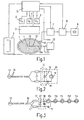
- Fig. 1, 1 denotes an examination object, which is in a Examination area is of a homogeneous stationary magnetic field is exposed, which is generated by a main field magnet 2.
- the stationary homogeneous magnetic field can be modified by means of three gradient arrangements 3, 4, 5 be a magnetic, in the direction of the homogeneous stationary magnetic field generate a gradient field that runs in the x, y or z direction Gradient.
- a high-frequency transmitter 6 is provided, which in Examination area can generate a high-frequency magnetic field.
- the object signals generated in the examination object are generated by a Receiving coil arrangement 14, which consists of one or more receiving coils can exist, detected in connection with a receiver arrangement 7. From the digitized object signals are processed after a suitable transformation, e.g. one Fourier transformation in a reconstruction unit 8 Nuclear magnetization distribution in the examination area reconstructed and in shape an MR image is reproduced on a display unit 9.
- a suitable transformation e.g. one Fourier transformation in a reconstruction unit 8 Nuclear magnetization distribution in the examination area reconstructed and in shape an MR image is reproduced on a display unit 9.
- a medical instrument 10 is inserted into the examination object 1, for example, a catheter, at the tip of which a microcoil 11 is attached can have a structure described in US Pat. No. 5,353,795.
- the Micro coil 11 is a capacitor 19, with the micro coil 11 a resonant circuit forms, and a modulation unit 12 is arranged.
- the modulation unit 12 is controlled by a control unit 13. That induced in the micro coil 11 and after a modulation by the modulation unit 12 from the micro coil 11 again radiated modulated coil signal is also from the Receiving coil arrangement 14 detected (the coil signal of the microcoil couples in the receiving coil arrangement 14) and processed by the components 7, 8.
- Components 2 to 8 and 13 are made by a programmable Control unit 15 controlled.
- the micro coil 11 forms together with the capacitor 19 a resonant circuit 20, the Resonance frequency to the Larmor frequency of the tissue to be examined Object 1 (e.g. the Larmor frequency of water).
- a PIN diode 18 is also inserted, which Modulation unit 12 forms.
- the PIN diode 18 is across two resistors or Choke coils 17 and a high-resistance two-wire line 16 with a control unit 13 connected, which supplies a rectangular AC voltage and thus the PIN diode 18 periodically toggles between the blocked and the through state.
- the coil 11 periodically sends a signal alternately (in the through state of the PIN diode 18) and sends no signal (in the blocked state the PIN diode 18). Since the switching frequency is significantly lower than that Resonance frequency of the resonant circuit 20, is therefore a modulation in the Coil 11 induced signal causes what is essentially in the frequency domain as a shift in the signal.
- the modulation frequency can be so be chosen that the coil signal by a known amount in Frequency range is shifted so that the coil signal from the object signal is separated. It is thereby achieved that with suitable computing means in the receiver unit 7 or the reconstruction unit 8, e.g. through filtering in the time or frequency domain, the coil signal is identified and the position the coil 11 can be determined and, if necessary, can be represented in the MR image.
- the receiving coil assembly 14 is of a sufficiently large size Frequency range tuned to not only the object signals but also the coil signals to be able to receive.
- the PIN diode 18 can be put into the blocking state to local To prevent changes in the excitation field strength by the resonant circuit 20.
- the PIN diode 18 can also be in the through state during the excitation be switched in order to obtain a higher signal amplitude from the coil 11.
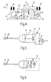
- FIG. 3 A second embodiment of the invention is shown in FIG. 3.
- Several Microcoils 11a to 11e are connected in series and with the capacitor 19 tuned to the Larmor frequency.
- the modulation unit 12 is here by a varactor (a capacitance diode) 37 is formed and is in turn via a high-resistance control line 16 connected to the control unit 13.
- the capacitor 19 By using a plurality of micro-coils 11a to 11e, which in small Distances of a few millimeters or centimeters along the catheter 10 are arranged, it is possible to trace the course of the catheter within the Object to be examined 1 over a larger distance and in the image display.
- the capacitor 19 In addition to tuning to the Larmor frequency in combination with the capacitor 38 and the varactor 37, the capacitor 19 also causes the varactor 37 does not have the same DC voltage due to the coils 11a to 11e is short-circuited.
- the capacitor 19 causes during the transmission phase together with the capacitor 38 a division of the induced RF voltage such that the reduced RF voltage at the varactor 37 is small enough, not this detune or generate unwanted signal components. Besides, can the tuning sensitivity of the resonance frequency can be reduced.
- a varactor 37 essentially has the advantage over a PIN diode 18 that that its capacity is voltage-dependent and that is why Manufacturing tolerances of coils and capacitors of the resonance circuit on the exact Larmor frequency can be tuned. Are in other configurations This means that other types of modulation than possible with a PIN diode are also possible.
- a PIN diode 18 may be provided in the embodiment shown in Fig. 3 . Only a micro coil 11a or could also be used a different number of micro-coils 11a to 11e can be provided. It could be the capacitor 38 is eliminated. It is also conceivable to use the capacitor 19 instead of the point shown between the upper terminals of the capacitor 38 and the Arrange elements 37.
- a receiver resonance circuit 31 which by a Parallel circuit is formed from a coil 21 and a capacitor 22, provided for receiving a radiation emitted by a transmitting unit 27 High-frequency control signal 28.
- the resonant circuit 31 is at the frequency of the Radio frequency control signal 28 tuned in a different frequency range lies as the Larmor frequency and the resonance frequency of the resonance circuit 20, to avoid mutual interference.
- the high-frequency control signal 28 indicates as shown, a rectangular envelope.
- the resonant circuit 20 is at this configuration as a parallel connection of the coil 11 and a capacitor 19 formed.
- the modulation unit 12 connected to the resonance circuit 31 has one here Field-effect transistor 26, at the gate G of which a gate voltage 30 is applied the transistor 26 periodically in the low-resistance or high-resistance state controls.
- the gate voltage 30 is connected to the resonance circuit 31 connected diode 23 and a parallel circuit of a capacitor 24 and a resistor 25 from that received by the resonant circuit 31 High-frequency control signal 28 derived.
- the Transistor 26 is impressed on resonant circuit 20 with the desired modulation, where the modulation frequency is the frequency of the rectangular envelope of the high-frequency control signal 28 is adjustable.
- a field effect transistor 26 can in the embodiment shown another controllable resistance or switching element can be used, the periodically by means of a control voltage in the conductive and non-conductive state or high-resistance and low-resistance state.
- Farther can between the drain terminal D of the transistor 26 and the resonant circuit 20th a capacitor 35 (indicated by dashed lines) can be provided, through which the coil 11 can be tuned to two different resonance frequencies: one first resonance frequency only with the capacitor 19 (in the blocking state of the Transistor 26) and to a second resonance frequency with the parallel connection of the Capacitors 19 and 35 (in the conductive state of transistor 26). This sends the coil 11 alternately with different phases and possibly also with different amplitudes, which in turn the transmitted coil signal in received MR signal is identifiable.
- the resonant circuit 20 can be tuned in this way be that the same signal amplitudes but one in both tuning states opposite phase difference (regarding the phase when the Resonance circuit 20 to the Larmor frequency). It becomes a pure one Phase modulation reached.
- FIG. 5 An embodiment with an optical control line 36 from the control unit 13 to the modulation unit 32 is shown in FIG. 5.
- the control lines 36 that For example, thin glass fiber cables can be provided with a light emitting diode 33 connected. This generates an optical control signal with which a suitable, optical controllable switching element, for example an optically controllable transistor 34, controlled and thereby periodically put in conductive and non-conductive state becomes.
- a suitable, optical controllable switching element for example an optically controllable transistor 34
- the Control unit 13 completely within the insertable part 10a (see Fig. 1) of the medical instrument 10, e.g. as an integrated Rectangular modulator with built-in battery. It could also be one Frequency converter circuit with amplifiers in the medical instrument 10 to get integrated.
- other switch arrangements are included other elements instead of the shown PIN diode, the varactor or the Transistor conceivable.
- FIG. 6 An embodiment with means for increasing the quality of the resonant circuit 20 is shown in Fig. 6.
- An element 36 is here parallel to the capacitor 19 negative resistor (a negative impedance converter) switched, the one Damping the resonance circuit causes and thereby an increase in the quality of the Resonant circuit 20 causes. This has the advantage that the one from the coil 11 significantly stronger signal can be coupled into the receiving coil arrangement.
- the element 36 can be realized in different ways, for example through a feedback field effect transistor.
- FIG. 7 shows the k-space (spatial frequency space) which has to be scanned with sufficient density in order to produce an MR image.
- the k-space is scanned along parallel lines running in the k x direction.
- the sampling rate is set so that the MR signal measured by the receiving coil arrangement, which contains the object signal and the coil signal, is sampled at uniform time intervals at the locations (x) denoted by k 1 .
- the modulation frequency was chosen such that the coil 11 only delivers a signal at every second sampling time, that is to say only at the points denoted by k 2 (o). This can be achieved, for example, in that the control signal of the control unit 13 is derived from the sampling rate by halving the frequency.
- the modulation frequency can also be selected such that the coil does not deliver a signal at every second sampling time (at the locations k 2 in FIG. 7), but only along every second horizontal k-line, but then at all sampling times k 1 , for example that the coil delivers a signal only along the lines k y1 , k y3 , etc. but not along the lines k y2 , k y4 , etc.
- With a suitable choice of the FOV or the number of measured k-lines it can be achieved that the additional image of the coil appears in an otherwise "empty" image area, which in turn enables easy identification and localization of the coil.
- the modulation could also be carried out in such a way that the resonance circuit is controlled in this way is that the coil alternately on the Larmor frequency and a frequency is not equal to the Larmor frequency. It is also conceivable to control the Modulation unit with a sinusoidal or other control voltage such that the resonant circuit has a phase and / or frequency modulation is imprinted.
- a phase modulation can be achieved, for example, in that the Modulation unit controls the resonant circuit in such a way that the coil alternately turns on a frequency above and below the Larmor frequency is tuned, whereby the distance between the resonance frequencies and the Larmor frequency advantageously about is chosen the same size, so that there is an approximately equal size in both cases Signal amplitude results.
- the amplitude of the transmitted signal does somewhat weaker than with resonance, but a transmission signal occurs in both Switching states.
- the two states differ from the Phase position with resonance by ⁇ ⁇ , e.g. by ⁇ 45 °, so that a total Phase difference of 2 ⁇ , e.g. of 90 ° results.
- This phase difference can be exploited by using the difference between two measured MR signals different phases to determine the coil signal and from this the position of the Calculate coil.
- This method is also suitable for use with a Projection reconstruction method and with radial scanning of k-space.
- the invention is not limited to any particular type of k-space scanning described types of modulation and the embodiments shown are limited. It is essential that the vibration of the Resonance circuit is modulated in some way so that from the measured MR signal, the coil signal can be separated and from this the position of the coil is determinable.
- Coil arrangement for the invention is also not the type and number of for Coil arrangement (s) used coils essential.
- s Coil arrangement
Description
Die Erfindung betrifft eine Magnetresonanz (MR)-Anordnung gemäß dem Oberbegriff
des Anspruchs 1. Die Erfindung betrifft außerdem ein medizinisches Instrument zum
Einführen in ein Untersuchungsobjekt, sowie ein Verfahren zur Positionsbestimmung
eines in ein Untersuchungsobjekt einführbaren medizinischen Instruments.The invention relates to a magnetic resonance (MR) arrangement according to the preamble
of
Eine ähnliche MR-Anordnung, medizinisches Instrument und Verfahren zu dessen Positionsbestimmung sind aus der US 5,353,795 bekannt. Dort ist eine kleine Hochfrequenzspule, eine sogenannte Mikrospule, in einem Katheter angeordnet, der in einen Patienten eingeführt wird. In die Mikrospule wird bei Betrieb der MR-Anordnung nach Anregung des Untersuchungsbereich ein hochfrequentes Signal induziert, das mittels einer Hochfrequenzleitung einer Empfängeranordnung zugeführt wird, die das Signal weiterarbeitet und die Position der Spule ermittelt. Diese Position kann dann in ein Bild, beispielsweise ein MR-Bild oder ein Computertomographie (CT)-Bild, eingeblendet werden.A similar MR arrangement, medical instrument and Methods for determining its position are known from US 5,353,795. There is a small high frequency coil, called a micro coil, in a catheter arranged, which is inserted into a patient. In operation, the MR arrangement after excitation of the examination area a high-frequency signal induced, which is fed to a receiver arrangement by means of a radio frequency line the signal continues to work and the position of the coil is determined. This position can then be converted into an image, for example an MR image or a computed tomography (CT) picture.
Bei der bekannten Anordnung erweist sich die erforderliche Hochfrequenzleitung von der außerhalb des Untersuchungsobjekts angeordneten Sender- und/oder Empfangsanordnung zu einer bevorzugt an der Spitze des medizinischen Instruments angeordneten Mikrospule als nachteilig. Es besteht die Gefahr von Gewebeaufheizungen durch entstehende Resonanzen (insbesondere λ/4-Resonanzen) in der Umgebung der Hochfrequenzleitung während der Sendephase (HF-Anregung) der MR-Untersuchung. Die Hochfrequenzleitung muß weiterhin zwangsweise durch sehr dünne Drähte gebildet werden, da das medizinische Instrument je nach Anwendung auch in sehr dünne Adern eingeführt werden muß. Dadurch können größere Signalverluste bei der Übertragung des empfangenen Signals von der Mikrospule zu einer Empfangsanordnung auftreten. Die Mikrospule muß zusammen mit der Hochfrequenzleitung außerdem einen stabilen Resonanzkreis bilden, weshalb die Länge der Hochfrequenzleitung nicht beliebig verändert werden kann. Bei der bekannten Anordnung wird außerdem ein separater Empfangskanal für die Mikrospule oder (bei Nutzung eines einzigen Empfangskanals) eine Umschaltvorrichtung zum Umschalten zwischen der Empfangsspulenanordnung und der Mikrospule benötigt.In the known arrangement, the required high-frequency line from the transmitter and / or receiver arrangement arranged outside the object to be examined to a microcoil preferably arranged at the tip of the medical instrument as a disadvantage. There is a risk of tissue heating due to arising Resonances (especially λ / 4 resonances) in the vicinity of the radio frequency line during the transmission phase (RF excitation) of the MR examination. The High-frequency line must continue to be formed by very thin wires because, depending on the application, the medical instrument can also be used in very thin veins must be introduced. This can cause larger signal losses when transmitting the received signal from the micro-coil to a receiving arrangement occur. The Microcoil must also be stable together with the radio frequency line Form resonance circuit, which is why the length of the radio frequency line does not change arbitrarily can be. In the known arrangement there is also a separate receiving channel for the microcoil or (when using a single reception channel) one Switching device for switching between the receiving coil arrangement and the Micro coil needed.
Weiterhin ist aus der EP-A-0 768 539 eine MR-Anordnung gemäß dem Oberbegriff des Anspruchs 1 bekannt, bei der die in der
Umgebung einer an einem in den Körper einführbaren Instrument befestigten Mikrospule
(im Vergleich zu den anderen Bereichen) erhöhte Kernmagnetisierung zur
Positionsbestimmung des Instruments ausgenutzt wird. Diese MR-Anordnung benötigt
zwar keine Hochfrequenzleitungen zum Anschluß der Mikrospule; die
Positionsbestimmung kann dabei aber nicht unmittelbar anhand eines von der Mikrospule
gelieferten Signals erfolgen, sondern ergibt sich aus einem MR-Bild, das aus den aus dem
Körper des Patienten empfangenen MR-Signalen rekonstruiert wird.Furthermore, an MR arrangement according to the preamble of
Der vorliegenden Erfindung liegt die Aufgabe zugrunde, eine verbesserte MR-Anordnung, ein verbessertes medizinisches Instrument und ein verbessertes Verfahren zur Positionsbestimmung eines solchen medizinischen Instruments anzugeben, wobei insbesondere die genannten Nachteile vermieden werden sollen.The present invention is based on the object of an improved MR arrangement, an improved medical instrument and method for Specify position determination of such a medical instrument, wherein in particular the disadvantages mentioned should be avoided.
Diese Aufgabe wird hinsichtlich der MR-Anordnung und hinsichtlich des medizinischen
Instruments erfindungsgemäß durch die Maßnahmen nach Anspruch 1 bzw. 10 gelöst.This task is done with regard to the MR arrangement and with regard to the medical
Instruments solved according to the invention by the measures according to
Die Hochfrequenzleitung zu einer außerhalb des Untersuchungsobjekts angeordneten Senderanordnung sowie die Senderanordnung selbst können bei der erfindungsgemäßen MR-Anordnung entfallen, da erfindungsgemäß das in die Spulenanordnung induzierte Signal nach einer Hochfrequenz-Anregung des im Untersuchungsbereich befindlichen Teils des Untersuchungsobjekts moduliert und mit dieser modulierten Frequenz und/oder Phase wieder abgestrahlt wird. Mit einer Empfangsspulenanordnung, die Teil der MR-Anordnung ist, wird als MR-Signal sowohl das von der Spulenanordnung gesendete (modulierte) Spulensignal als auch ein Objektsignal aus dem angeregten Bereich des Untersuchungsobjekts empfangen. Da diese Signale unterschiedliche Frequenzen und/oder Phasen aufweisen, ist auf einfache Weise eine Trennung des Spulensignals und des Objektsignals möglich, so daß auch die Bestimmung der Position der Spulenanordnung und damit der Position des medizinischen Instruments einfach möglich ist.The high-frequency line to an outside of the object to be examined Transmitter arrangement and the transmitter arrangement itself can be used in the inventive MR arrangements are dispensed with, since according to the invention this is induced in the coil arrangement Signal after high-frequency excitation of the one located in the examination area Part of the object being examined modulated and is emitted again with this modulated frequency and / or phase. With a Receiving coil arrangement, which is part of the MR arrangement, is called an MR signal both the (modulated) coil signal sent by the coil arrangement and receive an object signal from the excited area of the examination object. Since these signals have different frequencies and / or phases, is on a simple way to separate the coil signal and the object signal, so that also the determination of the position of the coil arrangement and thus the position of the medical instrument is easily possible.
Auch die in Verbindung mit einer Hochfrequenzleitung beschriebenen Nachteile treten demnach bei der erfindungsgemäßen MR-Anordnung nicht mehr auf, da weder von der Spulenanordnung an die Empfängeranordnung noch in umgekehrter Richtung Hochfrequenzsignale verlustarm übertragen werden müssen. Die bei der bekannten MR-Anordung erforderlichen niederohmigen Hochfrequenzleitungen können deshalb durch extrem dünne und hochohmige Leitungen ersetzt werden. Dadurch entfällt auch die Gefahr von Gewebeaufheizungen bei der erfindungsgemäßen MR-Anordnung und es ist kein zusätzlicher Empfangskanal oder eine Umschaltvorrichtung erforderlich.The disadvantages described in connection with a high-frequency line accordingly no longer occur in the MR arrangement according to the invention, since neither from the coil arrangement to the receiver arrangement nor in reverse Towards high-frequency signals must be transmitted with little loss. The at the known MR arrangement required low-resistance high-frequency lines can therefore be replaced by extremely thin and high-resistance cables. This also eliminates the risk of tissue heating at the MR arrangement according to the invention and it is not an additional reception channel or a switching device required.
Bei der bevorzugten Ausgestaltung gemäß Anspruch 2 sind die Elemente des
Resonanzkreises und die Modulationseinheit benachbart zueinander, beispielsweise
im Abstand von einigen Millimetern bis Zentimetern voneinander angeordnet, was
den Vorteil hat, daß keine oder nur sehr kurze Hochfrequenzleitungen zwischen
diesen Elementen erforderlich sind.In the preferred embodiment according to
Die Steuerleitung bei der Weiterbildung der Erfindung gemäß Anspruch 3 ist bevorzugt als hochohmige Zweidrahtleitung ausgestaltet, deren Länge beliebig gewählt sein kann und über die der Modulationseinheit ein niederfrequentes Steuersignal von der Steuereinheit zugeführt wird. Die Steuereinheit ist bevorzugt außerhalb des Untersuchungsobjekts angeordnet. The control line in the development of the invention according to claim 3 preferably designed as a high-resistance two-wire line, any length can be selected and via the modulation unit a low frequency Control signal is supplied from the control unit. The control unit is preferred arranged outside the object under examination.
Eine besonders einfache Möglichkeit der Steuerleitung bietet die Ausgestaltung der Erfindung gemäß Anspruch 4, bei der das Steuersignal auf optischem Wege zugeführt und mit geeigneten Mitteln, z.B. mit einer Art Optokoppler in ein elektrisches Steuersignal gewandelt wird.A particularly simple option for the control line is the configuration of the Invention according to claim 4, wherein the control signal is optically supplied and with suitable means, e.g. with a kind of optocoupler in one electrical control signal is converted.
Die Modulationseinheit kann besonders einfach und platzsparend aufgebaut sein und
weist im wesentlichen gemäß Anspruch 5 eine Schalteranordnung auf, die in der
entsprechenden geringen Größe hergestellt werden kann. Bevorzugt wird die
Schalteranordnung zwischen zwei Schaltzuständen umgeschaltet zur Modulation der
Schwingung des Resonanzkreises.The modulation unit can be constructed in a particularly simple and space-saving manner
essentially has a switch arrangement according to
Die bevorzugte Weiterbildung gemäß Anspruch 6 stellt eine völlig drahtlose Lösung
dar, bei der das Steuersignal als Hochfrequenz-Steuersignal in eine
Hochfrequenz-Empfangsanordnung induziert und in das eigentliche Steuersignal für
den Resonanzkreis umgewandelt wird. Die Frequenz des Hochfrequenz-Steuersignals
ist dabei deutlich größer oder kleiner als die Frequenz des in die Spulenanordnung
induzierten Signals und als die Resonanzfrequenz des Resonanzkreises, um
Störungen zu vermeiden. Vorteilhafterweise ist auch die
Hochfrequenz-Empfangsanordnung eng benachbart, beispielsweise im Abstand von
einigen Zentimetern zu der Modulationseinheit und dem Resonanzkreis angeordnet.The preferred development according to
Die Ausgestaltung gemäß Anspruch 8 ermöglicht insbesondere die Bestimmung der
Lage des medizinischen Instruments in einem größeren Bereich, in dem die Spulen
angeordnet sind, indem die Position der einzelnen Spulen bestimmt wird, deren
Position in oder an dem Instrument bekannt ist.The embodiment according to
Gemäß Anspruch 9 können auch mehrere Resonanzkreise vorgesehen sein, die auch unterschiedlich moduliert werden, z.B. mit unterschiedlichen Frequenzen, so daß die Position jeder einzelnen Spulenanordnung eindeutig bestimmbar ist, indem z.B. jede Spulenanordnung in einem anderen Bildbereich abgebildet wird. According to claim 9, several resonance circuits can also be provided, which too can be modulated differently, e.g. with different frequencies so that the The position of each individual coil arrangement can be clearly determined, e.g. by each Coil arrangement is mapped in another image area.
Die Aufgabe betreffend das Verfahren zur Positionsbestimmung eines medizinischen Instruments wird dadurch gelöst, daß die Spulenanordnung mit einem Kondensator einen Resonanzkreis bildet, daß ein in die Spulenanordnung eingekoppeltes Hochfrequenzsignal derart moduliert wird, daß im MR-Signal ein moduliertes und von der Spulenanordnung wieder abgestrahltes Spulensignal enthalten ist, und daß aus dem Spulensignal die Position des Instruments ermittelt wird.The task regarding the method for determining the position of a medical Instruments is solved in that the coil arrangement with a capacitor forms a resonant circuit that is coupled into the coil arrangement High-frequency signal is modulated in such a way that a modulated in the MR signal and by the Coil arrangement again emitted coil signal is included, and that the position of the coil signal Instruments is determined.
Bei dem erfindungsgemäßen Verfahren ist eine deutlich einfachere Positionsbestimmung der Spulenanordnung als bei dem bekannten Verfahren möglich. Durch die erfindungsgemäße Modulation, bei der dem in die Spulenanordnung induzierten Signal eine Frequenzverschiebung oder eine Phasendrehung aufgeprägt wird, ist das von der Spulenanordnung wieder abgestrahlte modulierte Spulensignal mit einfachen Rechenverfahren aus dem von der Empfangsspulenanordnung empfangenen MR-Signal abtrennbar.In the method according to the invention, a much simpler one Position determination of the coil arrangement than in the known method possible. By the modulation according to the invention, in which the Coil arrangement induced a frequency shift or a signal Phase rotation is impressed, that is again from the coil arrangement radiated modulated coil signal with simple calculation methods from that of the received MR array received MR signal separable.
In den Ansprüchen 12 bis 14 sind vorteilhafte Ausgestaltungen des
erfindungsgemäßen Verfahrens angegeben, insbesondere vorteilhafte Arten der
Modulation.In the
Die Erfindung wird nachfolgend anhand der Zeichnung näher erläutert. Es zeigen:
- Fig. 1
- ein Blockschaltbild einer erfindungsgemäßen MR-Anordnung,
- Fig. 2
- ein Ersatzschaltbild einer ersten Ausführungsform der Erfindung,
- Fig. 3
- ein Ersatzschaltbild einer zweiten Ausführungsform der Erfindung,
- Fig. 4
- ein Ersatzschaltbild einer dritten Ausführungsform der Erfindung mit drahtloser Zuführung des Steuersignals,
- Fig. 5
- ein Ersatzschaltbild einer vierten Ausführungsform der Erfindung mit optischer Zuführung des Steuersignals,
- Fig. 6
- ein Ersatzschaltbild einer Ausführungsform der Erfindung mit Mitteln zur Entdämfpung des Resonanzkreises,
- Fig. 7
- eine Darstellung des k-Raumes zur Erläuterung des erfindungsgemäßen Verfahrens und
- Fig. 8
- eine Darstellung gemessener Signale.
- Fig. 1
- 2 shows a block diagram of an MR arrangement according to the invention,
- Fig. 2
- an equivalent circuit diagram of a first embodiment of the invention,
- Fig. 3
- an equivalent circuit diagram of a second embodiment of the invention,
- Fig. 4
- 2 shows an equivalent circuit diagram of a third embodiment of the invention with wireless supply of the control signal,
- Fig. 5
- 4 shows an equivalent circuit diagram of a fourth embodiment of the invention with optical supply of the control signal,
- Fig. 6
- 2 shows an equivalent circuit diagram of an embodiment of the invention with means for damping the resonance circuit,
- Fig. 7
- a representation of the k-space to explain the inventive method and
- Fig. 8
- a representation of measured signals.
In Fig. 1 ist mit 1 ein Untersuchungsobjekt bezeichnet, das sich in einem
Untersuchungsbereich befindet, der einem homogenen stationären Magnetfeld
ausgesetzt ist, das von einem Haupfeldmagneten 2 erzeugt wird. Das stationäre
homogene Magnetfeld kann mittels dreier Gradientenanordnungen 3, 4, 5 modifiziert
werden, die ein magnetisches, in Richtung des homogenen stationären Magnetfeldes
verlaufendes Gradientenfeld erzeugen, das in x-, y- oder z-Richtung einen
Gradienten aufweist. Weiterhin ist ein Hochfrequenz-Sender 6 vorgesehen, der im
Untersuchungsbereich impulsweise ein hochfrequentes Magnetfeld erzeugen kann.In Fig. 1, 1 denotes an examination object, which is in a
Examination area is of a homogeneous stationary magnetic field
is exposed, which is generated by a
Die im Untersuchungsobjekt erzeugten Objektsignale werden von einer
Empfangsspulen-Anordnung 14, die aus einer oder mehreren Empfangsspulen
bestehen kann, in Verbindung mit einer Empfängeranordnung 7 detektiert. Aus den
digitalisierten Objektsignalen wird nach einer geeigneten Transformation, z.B. einer
Fourier-Transformation in einer Rekonstruktionseinheit 8 die
Kernmagnetisierungsverteilung im Untersuchungsbereich rekonstruiert und in Form
eines MR-Bildes auf einer Wiedergabeeinheit 9 wiedergegeben.The object signals generated in the examination object are generated by a
Receiving coil arrangement 14, which consists of one or more receiving coils
can exist, detected in connection with a
In das Untersuchungsobjekt 1 ist ein medizinisches Instrument 10 eingeführt,
beispielsweises ein Katheter, an dessen Spitze eine Mikrospule 11 befestigt ist, die
einen in der US 5,353,795 beschriebenen Aufbau haben kann. In oder an dem in das
Untersuchungsobjekt 1 eingeführten Teil 10a des Katheters 10 ist in der Nähe der
Mikrospule 11 ein Kondensator 19, der mit der Mikrospule 11 einen Resonanzkreis
bildet, und eine Modulationseinheit 12 angeordnet. Die Modulationseinheit 12 wird
von einer Steuereinheit 13 gesteuert. Das in die Mikrospule 11 induzierte und nach
einer Modulation durch die Modulationseinheit 12 von der Mikrospule 11 wieder
abgestrahlte modulierte Spulensignal wird ebenfalls von der
Empangsspulen-Anordnung 14 erfaßt (das Spulensignal der Mikrospule koppelt in
die Empfangssspulen-Anordnung 14) und von den Komponenten 7, 8 verarbeitet.
Die Komponenten 2 bis 8 sowie 13 werden von einer programmierbaren
Steuereinheit 15 gesteuert.A
In Fig. 2 ist eine erste Ausführungsform der Erfindung dargestellt. Die Mikrospule
11 bildet zusammen mit dem Kondensator 19 einen Resonanzkreis 20, dessen
Resonanzfrequenz auf die Larmor-Frequenz des zu untersuchenden Gewebes des
Untersuchungsobjekts 1 (z.B. auf die Larmor-Frequenz von Wasser) abgestimmt ist.
In den Resonanzkreis 20 ist außerdem eine PIN-Diode 18 eingefügt, die die
Modulationseinheit 12 bildet. Die PIN-Diode 18 ist über zwei Widerstände oder
Drosselspulen 17 und eine hochohmige Zweidrahtleitung 16 mit einer Steuereinheit
13 verbunden, die eine rechteckförmige Wechselspannung liefert und damit die
PIN-Diode 18 periodisch zwischen Sperr- und Durchgangszustand umschaltet.
Dadurch wird erreicht, daß die Spule 11 abwechselnd periodisch ein Signal sendet
(im Durchgangszustand der PIN-Diode 18) und kein Signal sendet (im Sperrzustand
der PIN-Diode 18). Da die Schaltfrequenz deutlich niedriger ist als die
Resonanzfrequenz des Resonanzkreises 20, wird folglich eine Modulation des in die
Spule 11 induzierten Signals bewirkt, was sich im Frequenzbereich im wesentlichen
als eine Verschiebung des Signals auswirkt. Die Modulationsfrequenz kann dabei so
gewählt werden, daß das Spulensignal um einen bekannten Betrag im
Frequenzbereich verschoben wird, so daß das Spulensignal vom Objektsignal
getrennt wird. Dadurch wird erreicht, daß mit geeigneten rechnerischen Mitteln in
der Empfängereinheit 7 oder der Rekonstruktionseinheit 8, z.B. durch eine Filterung
im Zeit- oder Frequenzbereich, das Spulensignal identifiziert und daraus die Position
der Spule 11 bestimmt und gegebenenfalls im MR-Bild dargestellt werden kann.2 shows a first embodiment of the invention. The
Die Empfangsspulen-Anordnung 14 ist in einem ausreichend großen
Frequenzbereich abgestimmt, um neben den Objektsignalen auch die Spulensignale
empfangen zu können. Während der Anregung durch den Hochfrequenz-Sender 6
kann die PIN-Diode 18 in den Sperrzustand versetzt werden, um lokale
Veränderungen der Anregungsfeldstärke durch den Resonanzkreis 20 zu verhindern.
Die PIN-Diode 18 kann jedoch auch während der Anregung im Durchgangszustand
geschaltet sein, um eine höhere Signalamplitude von der Spule 11 zu erhalten.The receiving coil assembly 14 is of a sufficiently large size
Frequency range tuned to not only the object signals but also the coil signals
to be able to receive. During the excitation by the
Eine zweite Ausführungsform der Erfindung ist in Fig. 3 dargestellt. Mehrere
Mikrospulen 11a bis 11e sind dabei in Serie geschaltet und mit dem Kondensator 19
auf die Larmor-Frequenz abgestimmt. Die Modulationseinheit 12 wird hier durch
einen Varaktor (eine Kapazitätsdiode) 37 gebildet und ist wiederum über eine
hochohmige Steuerleitung 16 mit der Steuereinheit 13 verbunden.A second embodiment of the invention is shown in FIG. 3. Several
Microcoils 11a to 11e are connected in series and with the
Durch die Verwendung mehrerer Mikrospulen 11a bis 11e, die in geringen
Abständen von wenigen Millimetern oder Zentimetern entlang des Katheters 10
angeordnet sind, ist es möglich, den Verlauf des Katheters innerhalb des
Untersuchungsobjekts 1 über eine größere Strecke zu bestimmen und im Bild
darzustellen. Neben der Abstimmung auf die Larmor-Frequenz in Kombination mit
dem Kondensator 38 und dem Varaktor 37 bewirkt der Kondensator 19 auch, daß
der Varaktor 37 durch die Spulen 11a bis 11e gleichspannungsmäßig nicht
kurzgeschlossen ist. Außerdem bewirkt der Kondensator 19 während der Sendephase
zusammen mit dem Kondensator 38 eine Aufteilung der induzierten HF-Spannung
derart, daß die reduzierte HF-Spannung am Varaktor 37 klein genug ist, diesen nicht
zu verstimmen oder unerwünschte Signalkomponenten zu erzeugen. Außerdem kann
die Abstimmempfindlichkeit der Resonanzfrequenz reduziert werden.By using a plurality of micro-coils 11a to 11e, which in small
Distances of a few millimeters or centimeters along the
Ein Varaktor 37 hat gegenüber einer PIN-Diode 18 im wesentlichen den Vorteil,
daß dessen Kapazität spannungsabhängig ist und daß deshalb auch bei
Fertigungstoleranzen von Spulen und Kondensatoren der Resonanzkreis auf die
genaue Larmor-Frequenz abgestimmt werden kann. In anderen Ausgestaltungen sind
damit auch andere Modulationsarten als mit einer PIN-Diode möglich. A
Bei der in Fig. 3 gezeigten Ausführungsform könnte anstelle des Varaktors auch
eine PIN-Diode 18 vorgesehen sein. Es könnten auch nur eine Mikrospule 11a oder
eine andere Anzahl von Mikrospulen 11a bis 11e vorgesehen sein. Es könnte auch
der Kondensator 38 entfallen. Denkbar ist auch, den Kondensator 19 statt an der
gezeigten Stelle zwischen den oberen Anschlüssen des Kondensators 38 und des
Elements 37 anzuordnen.In the embodiment shown in Fig. 3 could also instead of the varactor
a
Eine Ausführungsform mit einer drahtlosen Steuerung der Modulationseinheit 12 ist
in Fig. 4 gezeigt. Dort ist ein Empfänger-Resonanzkreis 31, der durch eine
Parallelschaltung aus einer Spule 21 und einem Kondensator 22 gebildet ist,
vorgesehen zum Empfang eines von einer Sendeeinheit 27 eingestrahlten
Hochfrequenz-Steuersignals 28. Der Resonanzkreis 31 ist auf die Frequenz des
Hochfrequenz-Steuersignals 28 abgestimmt, die in einem anderen Frequenzbereich
liegt als die Larmor-Frequenz und die Resonanzfrequenz des Resonanzkreises 20,
um gegenseitige Störungen zu vermeiden. Das Hochfrequenz-Steuersignal 28 weist,
wie gezeigt, eine rechteckförmige Hüllkurve auf. Der Resonanzkreis 20 ist bei
dieser Ausgestaltung als Parallelschaltung aus der Spule 11 und einem Kondensator
19 gebildet.One embodiment with wireless control of the
Die mit dem Resonanzkreis 31 verbundene Modulationseinheit 12 weist hier einen
Feldeffekt-Transistor 26 auf, an dessen Gate G eine Gate-Spannung 30 anliegt, die
den Transistor 26 periodisch in den niederohmigen bzw. hochohmigen Zustand
steuert. Die Gate-Spannung 30 wird mittels einer mit dem Resonanzkreis 31
verbundenen Diode 23 und einer Parallelschaltung aus einem Kondensator 24 und
einem Widerstand 25 aus dem von dem Resonanzkreis 31 empfangenen
Hochfrequenz-Steuersignal 28 abgeleitet. Durch das periodische Umschalten des
Transistors 26 wird dem Resonanzkreis 20 die gewünschte Modulation aufgeprägt,
wobei die Modulationsfrequenz durch die Frequenz der rechteckförmigen Hüllkurve
des Hochfrequenz-Steuersignals 28 einstellbar ist. The
Anstelle eines Feldeffekt-Transistors 26 kann bei der gezeigten Ausführungsform
auch ein anderes steuerbares Widerstands- oder Schaltelement eingesetzt werden, das
periodisch mittels eines Steuerspannung in leitenden und nicht-leitenden Zustand
oder hochohmigen und niederohmigen Zustand versetzt werden kann. Weiterhin
kann zwischen dem Drain-Anschluß D des Transistors 26 und dem Resonanzkreis 20
ein (gestrichelt angedeuteter) Kondensator 35 vorgesehen sein, durch den die Spule
11 auf zwei unterschiedliche Resonanzfrequenzen abgestimmt werden kann: auf eine
erste Resonanzfrequenz nur mit dem Kondensator 19 (im Sperrzustand des
Transistors 26) und auf eine zweite Resonanzfrequenz mit der Parallelschaltung der
Kondensatoren 19 und 35 (im leitenden Zustand des Transistors 26). Dadurch sendet
die Spule 11 abwechselnd mit unterschiedlichen Phasen und ggf. auch mit
unterschiedlichen Amplituden, wodurch wiederum das gesendete Spulensignal im
empfangenen MR-Signal identifizierbar ist.Instead of a
In einer bevorzugten Ausführungsform kann der Resonanzkreis 20 so abgestimmt
werden, daß sich in beiden Abstimmzuständen gleiche Signal-Amplituden aber eine
entgegengesetzte Phasendifferenz (bezüglich der Phase bei Abstimmung des
Resonanzkreises 20 auf die Larmor-Frequenz) einstellt. Damit wird eine reine
Phasenmodulation erreicht.In a preferred embodiment, the
Eine Ausführungsform mit einer optischen Steuerleitung 36 von der Steuereinheit 13
an die Modulationseinheit 32 ist in Fig. 5 gezeigt. Die Steuerleitungen 36, die
beispielsweise dünne Glasfaserkabel sein können, sind mit einer Leuchtdiode 33
verbunden. Diese erzeugt ein optisches Steuersignal, mit dem ein geeignetes, optisch
steuerbares Schaltelement, beispielsweise ein optisch steuerbarer Transistor 34,
gesteuert und dadurch periodisch in leitenden und nicht-leitenden Zustand versetzt
wird. Die übrige Funktionsweise gleicht im wesentlichen der im Zusammenhang mit
Fig. 4 beschriebenen Funktionsweise. An embodiment with an
Als Modulationseinheit 32 ist auch der Einsatz eines einzigen Bauelements, z.B. eines geeigneten Optokopplers vorstellbar.The use of a single component, e.g. a suitable optocoupler.
Neben den beschriebenen Ausführungsformen sind auch weitere Möglichkeiten der
Ausgestaltung der Modulationseinheit denkbar. Beispielsweise könnte die
Steuereinheit 13 völlig innerhalb des einführbaren Teils 10a (siehe Fig. 1) des
medizinischen Instruments 10 angeordnet sein, z.B. als integrierter
Rechteck-Modulator mit eingebauter Batterie. Es könnte auch eine
Frequenz-Umsetzer-Schaltung mit Verstärkern in das medizinische Instrument 10
integriert werden. Darüber hinaus sind auch andere Schalteranordnungen mit
anderen Elementen anstelle der gezeigten PIN-Diode, des Varaktors oder des
Transistors denkbar.In addition to the described embodiments, other options are also available
Design of the modulation unit conceivable. For example, the
Eine Ausführungsform mit Mitteln zur Erhöhung der Güte des Resonanzkreises 20
ist in Fig. 6 dargestellt. Parallel zum Kondensator 19 ist hier ein Element 36 mit
negativem Widerstand (ein negativer Impedanzkonverter) geschaltet, das eine
Entdämpfung des Resonanzkreises bewirkt und dadurch eine Erhöhung der Güte des
Resonanzkreises 20 bewirkt. Dies hat den Vorteil, das das von der Spule 11 ein
deutlich stärkeres Signal in die Empfangsspulenanordnung gekoppelt werden kann.
Die Realisierung des Elements 36 kann unterschiedlich erfolgen, beispielsweise
durch einen rückgekoppelten Feldeffekttransistor.An embodiment with means for increasing the quality of the
Anhand der Fig. 7 und 8 soll das erfindungsgemäße Verfahren näher erläutert und unterschiedliche Modulationsarten, die mit den in den Fig. 2 bis 6 gezeigten Ausführungsformen umgesetzt werden können, verdeutlicht werden.The method according to the invention is to be explained in more detail with reference to FIGS. 7 and 8 different types of modulation with those shown in Figs. 2 to 6 Embodiments can be implemented, clarified.
Fig. 7 zeigt den k-Raum (Ortsfrequenzraum), der zur Erstellung eines MR-Bildes
mit ausreichender Dichte abgetastet werden muß. Im gezeigten Beispiel wird der
k-Raum entlang paralleler in kx-Richtung verlaufender Linien abgetastet. Die
Abtastrate ist dabei so eingestellt, daß das von der Empfangsspulenanordnung
gemessene MR-Signal, das das Objektsignal und das Spulensignal enthält, in
gleichmäßigen Zeitabständen an den mit k1 bezeichneten Stellen (x) abgetastet wird.
Die Modulationsfrequenz wurde bei dem gezeigten Beispiel so gewählt, daß die
Spule 11 nur zu jedem zweiten Abtastzeitpunkt, also nur an den mit k2 (o)
bezeichneten Stellen ein Signal liefert. Dies kann z.B. dadurch erreicht werden, daß
das Steuersignal der Steuereinheit 13 duch Frequenzhalbierung aus der Abtastrate
abgeleitet wird. Da von der Spule nur zu jedem zweiten Abtastpunkt k2 ein Signal
geliefert wird, ist dies gleichbedeutend mit einer Unterabtastung gegenüber dem
Objektsignal, das zu jedem Abtastpunkt k1 ein Signal liefert. Dies bewirkt eine
Wiederholung der Abbildung der Spule im Ortsbereich an einer anderen Stelle. Bei
der beschriebenen Wahl der Modulationsfrequenz ergibt sich eine Abbildung S2 der
Spule im Ortsbereich (r) horizontal versetzt um genau eine halbe Bildbreite. Wird
die Abtastrate doppelt so groß gewählt (Überabtastung), wie zur Abbildung (des
Field-of View = FOV) erforderlich ist, dann ergibt sich das resultierende MR-Bild
doppelt so breit wie ein herkömmliches MR-Bild (Vergrößerung in Ausleserichtung),
wobei das Objekt selbst zwischen -fov/2 und +fov/2 abgebildet wird (S1) (siehe Fig.
8), während zwischen + 1/2 fov und 3/2 fov nur die Spule abgebildet ist. In dieser
Bildhälfte läßt sich dann einfach die Spule identifizieren, ihre Position bestimmen
und ggf. in die andere Bildhälfte einblenden.FIG. 7 shows the k-space (spatial frequency space) which has to be scanned with sufficient density in order to produce an MR image. In the example shown, the k-space is scanned along parallel lines running in the k x direction. The sampling rate is set so that the MR signal measured by the receiving coil arrangement, which contains the object signal and the coil signal, is sampled at uniform time intervals at the locations (x) denoted by k 1 . In the example shown, the modulation frequency was chosen such that the
Die Modulationsfrequenz kann auch derart gewählt werden, daß die Spule nicht zu jedem zweiten Abtastzeitpunkt (an den Stellen k2 in Fig. 7), sondern nur entlang jeder zweiten horizontalen k-Linie ein Signal liefert, aber dann zu allen Abtastzeitpunkten k1, z.B. daß die Spule nur entlang der Linien ky1, ky3, usw. nicht aber entlang der Linien ky2, ky4, usw. ein Signal liefert. Dadurch entsteht ein weiteres Abbild der Spule um genau eine halbe Bildhöhe vertikal versetzt (Vergrößerung des Bildes in Phasenkodierrichtung). Durch geeignete Wahl des FOV bzw. der Anzahl der gemessenen k-Linien kann erreicht werden, daß das zusätzliche Abbild der Spule in einem sonst "leeren" Bildbereich erscheint, wodurch wiederum eine einfach Identifikation und Lokalisation der Spule möglich ist. The modulation frequency can also be selected such that the coil does not deliver a signal at every second sampling time (at the locations k 2 in FIG. 7), but only along every second horizontal k-line, but then at all sampling times k 1 , for example that the coil delivers a signal only along the lines k y1 , k y3 , etc. but not along the lines k y2 , k y4 , etc. This creates a further image of the coil vertically offset by exactly half an image height (enlargement of the image in the phase coding direction). With a suitable choice of the FOV or the number of measured k-lines it can be achieved that the additional image of the coil appears in an otherwise "empty" image area, which in turn enables easy identification and localization of the coil.
Die Modulation könnte auch derart erfolgen, daß der Resonanzkreis derart gesteuert wird, daß die Spule abwechselnd auf die Larmorfrequenz und eine Frequenz ungleich der Larmorfrequenz abgestimmt ist. Denkbar ist auch eine Ansteuerung der Modulationseinheit mit einer sinusförmigen oder einer anderen Steuerspannung derart, daß dem Resonanzkreis eine Phasen- und/oder Frequenzmodulation aufgeprägt wird.The modulation could also be carried out in such a way that the resonance circuit is controlled in this way is that the coil alternately on the Larmor frequency and a frequency is not equal to the Larmor frequency. It is also conceivable to control the Modulation unit with a sinusoidal or other control voltage such that the resonant circuit has a phase and / or frequency modulation is imprinted.
Eine Phasenmodulation kann beispielsweise dadurch erreicht werden, daß die Modulationseinheit den Resonanzkreis derart steuert, daß die Spule abwechselnd auf eine Frequenz oberhalb und unterhalb der Larmorfrequenz abgestimmt wird, wobei der Abstand der Resonanzfrequenzen zur Larmorfrequenz vorteilhafterweise etwa gleich groß gewählt wird, so daß sich in beiden Fällen eine etwa gleich große Signalamplitude ergibt. Zwar wird die Amplitude des gesendeten Signals dadurch etwas schwächer als bei Resonanz, ein Sendesignal tritt dafür aber in beiden Schaltzuständen auf. Die beiden Zustände unterscheiden sich dabei von der Phasenlage bei Resonanz um jeweils ±ϕ, z.B. um ±45°, so daß sich insgesamt ein Phasenunterschied von 2ϕ, z.B. von 90° ergibt. Dieser Phasenunterschied kann ausgenutzt werden, um durch Differenzbildung zweier gemessener MR-Signale mit unterschiedlichen Phasen das Spulensignal zu ermitteln und daraus die Position der Spule zu berechnen. Dieses Verfahren eignet sich auch zur Anwendung bei einem Projektions-Rekonstruktionsverfahren und bei radialer Abtastung des k-Raumes.A phase modulation can be achieved, for example, in that the Modulation unit controls the resonant circuit in such a way that the coil alternately turns on a frequency above and below the Larmor frequency is tuned, whereby the distance between the resonance frequencies and the Larmor frequency advantageously about is chosen the same size, so that there is an approximately equal size in both cases Signal amplitude results. The amplitude of the transmitted signal does somewhat weaker than with resonance, but a transmission signal occurs in both Switching states. The two states differ from the Phase position with resonance by ± ϕ, e.g. by ± 45 °, so that a total Phase difference of 2ϕ, e.g. of 90 ° results. This phase difference can can be exploited by using the difference between two measured MR signals different phases to determine the coil signal and from this the position of the Calculate coil. This method is also suitable for use with a Projection reconstruction method and with radial scanning of k-space.
Die Erfindung ist nicht auf eine bestimmte Art der Abtastung des k-Raumes, auf die beschriebenen Modulationsarten und die gezeigten Ausführungsbeispiele beschränkt. Wesentlich ist, daß durch die Modulationseinheit die Schwingung des Resonanzkreises in irgendeiner Weise moduliert wird, so daß aus dem gemessenen MR-Signal das Spulensignal abtrennbar und daraus die Position der Spule bestimmbar ist. The invention is not limited to any particular type of k-space scanning described types of modulation and the embodiments shown are limited. It is essential that the vibration of the Resonance circuit is modulated in some way so that from the measured MR signal, the coil signal can be separated and from this the position of the coil is determinable.
Für die Erfindung ist auch nicht die Art und die Anzahl der für die Spulenanordnung(en) verwendeten Spulen wesentlich. Beispielsweise könnten statt der gezeigten Mikrospulen Spulen mit einem größeren Durchmesser oder Spulenanordungen mit drei Spulen mit zueinander senkrecht verlaufenden Spulenachsen verwendet werden, die nebeneinander oder um einen gemeinsamen Mittelpunkt angeordnet sind.For the invention is also not the type and number of for Coil arrangement (s) used coils essential. For example, instead of of the micro-coils shown coils with a larger diameter or Coil arrangements with three coils with mutually perpendicular Coil axes are used side by side or around a common one Center are arranged.
Es ist auch denkbar, mehrere Resonanzkreise mit je einer Spulenanordnung (z.B. mit je einer Mikrospule) parallel zu betreiben mit jeweils einer zugeordneten Modulationseinheit und die Resonanzkreise unterschiedlich (z.B. mit unterschiedlichen Frequenzen) zu modulieren, wodurch die Spulensignale der Spulenanordnungen in verschiedenen Bildbereichen des MR-Bildes erscheinen und deshalb die einzelnen Spulenanordnungen identifiziert und lokalisiert werden können.It is also conceivable to use several resonance circuits, each with a coil arrangement (e.g. with one micro coil each) to be operated in parallel with one assigned Modulation unit and the resonance circuits different (e.g. with different frequencies), which modulates the coil signals of the Coil arrangements appear in different image areas of the MR image and therefore the individual coil arrangements are identified and localized can.
Claims (14)
- An MR device which is provided with a medical instrument (10) which is to be introduced into an object (1) to be examined, and also with a coil system (11) which is arranged in or on the instrument (10), constitutes a resonant circuit (20) in conjunction with a capacitor (19) and includes at least one coil, characterized in that the coil system (11) is provided with a modulation unit (12) for modulating an RF signal which is coupled into the coil system (11), and emitted again by the coil system.
- An MR device as claimed in claim 1, characterized in that the modulation unit (12), the capacitor (19) and the coil system (11) are arranged at a small distance from one another and in or on the part (10a) of the instrument (10) that can be introduced into the object (1) to be examined.
- An MR device as claimed in claim 1, characterized in that a control lead (16) is provided between a control unit (13) for controlling the modulation unit (12) and the modulation unit.
- An MR device as claimed in claim 3, characterized in that the control lead (36) is an optical fiber cable and that the modulation unit (32) is arranged to convert an optical control signal into an electrical control signal.
- An MR device as claimed in claim 1, characterized in that the modulation unit (12) includes a switch arrangement, which includes notably a diode (18), a varactor (37), a transistor (26) or an integrated switching element.
- An MR device as claimed in claim 1, characterized in that there is provided an RF receiving device (31), notably a receiver resonant circuit with a coil (21) and a capacitor (22), for receiving an RF control signal (28) transmitted by an RF control unit (27), and that the modulation unit (12) includes means for converting the RF control signal (28) into a modulation signal (29) for the resonant circuit (20).
- An MR device as claimed in claim 6, characterized in that the RF control unit (27) and the modulation unit (12) are arranged for wireless transmission of the RF control signal (28).
- An MR device as claimed in claim 1, characterized in that the coil system (11) comprises a plurality of coils (1la, 11b, 11c, 11d, 11e) which are connected in series and are arranged notably at a small distance from one another.
- An MR device as claimed in claim 1, characterized in that a plurality of resonant circuits (20), each of which includes an associated modulation unit (12), are arranged in or on the instrument (10), and that the RF signals coupled into the coil system (11) are modulated differently by the modulation units (12).
- A medical instrument (10) which is to be introduced into an object (1) to be examined, notably a catheter or an endoscope, and includes a coil system (11) which is arranged in or on the instrument (10) and includes at least one coil for receiving and/or transmitting an RF signal, in which the coil system (11) constitutes a resonant circuit (20) in conjunction with a capacitor (19), characterized in that there is provided a modulation unit (12) for modulating an RF signal which is coupled into the coil system (11) and emitted again by coil system.
- A method of determining the position of a medical instrument (10) which can be introduced into an object (1) to be examined, the object (1) to be examined being arranged in the examination zone of an MR device, a coil system (11) which constitutes a resonant circuit (20) in conjunction with a capacitor (19) and which includes at least one coil for receiving and/or transmitting an RF signal being arranged in or on the medical instrument (10) and the position of the instrument (10) being determined from an MR signal received by a receiving coil system (14), characterized in that the coil system (11) modulates an RF signal coupled into the coil system (11) in such a manner that a modulated coil signal which is emitted again by the coil system is contained in the MR signal, and that the position of the instrument is determined from the coil signal.
- A method as claimed in claim 11, characterized in that the oscillation of the resonant circuit (20) is switched on and off at a switching frequency for the purpose of modulation.
- A method as claimed in claim 11, characterized in that the modulation is performed in such a manner that the resonant circuit (20) is tuned alternately to a frequency which is equal to and to a frequency which is not equal to the frequency of the RF signal coupled into the coil system (11).
- A method as claimed in claim 11, characterized in that the modulation is performed in such a manner that the resonant circuit (20) is tuned alternately to a frequency above or unequal to the frequency of the RF signal coupled into the coil system (11).
Applications Claiming Priority (2)
| Application Number | Priority Date | Filing Date | Title |
|---|---|---|---|
| DE19755782 | 1997-12-16 | ||
| DE19755782A DE19755782A1 (en) | 1997-12-16 | 1997-12-16 | Magnetic resonance device |
Publications (3)
| Publication Number | Publication Date |
|---|---|
| EP0930509A2 EP0930509A2 (en) | 1999-07-21 |
| EP0930509A3 EP0930509A3 (en) | 2001-04-11 |
| EP0930509B1 true EP0930509B1 (en) | 2004-03-17 |
Family
ID=7852032
Family Applications (1)
| Application Number | Title | Priority Date | Filing Date |
|---|---|---|---|
| EP98204162A Expired - Lifetime EP0930509B1 (en) | 1997-12-16 | 1998-12-08 | MR device comprising a medical instrument and method for determining the location of the medical instrument |
Country Status (4)
| Country | Link |
|---|---|
| US (1) | US6236205B1 (en) |
| EP (1) | EP0930509B1 (en) |
| JP (1) | JPH11239572A (en) |
| DE (2) | DE19755782A1 (en) |
Cited By (24)
| Publication number | Priority date | Publication date | Assignee | Title |
|---|---|---|---|---|
| US7363090B2 (en) | 2001-04-13 | 2008-04-22 | Greatbatch Ltd. | Band stop filter employing a capacitor and an inductor tank circuit to enhance MRI compatibility of active implantable medical devices |
| US7822460B2 (en) | 1998-11-04 | 2010-10-26 | Surgi-Vision, Inc. | MRI-guided therapy methods and related systems |
| US7853325B2 (en) | 2001-04-13 | 2010-12-14 | Greatbatch Ltd. | Cylindrical bandstop filters for medical lead systems |
| US7920916B2 (en) | 2006-11-09 | 2011-04-05 | Greatbatch Ltd. | Capacitor and inductor elements physically disposed in series whose lumped parameters are electrically connected in parallel to form a bandstop filter |
| US7945322B2 (en) | 2005-11-11 | 2011-05-17 | Greatbatch Ltd. | Tank filters placed in series with the lead wires or circuits of active medical devices to enhance MRI compatibility |
| USRE42856E1 (en) | 2002-05-29 | 2011-10-18 | MRI Interventions, Inc. | Magnetic resonance probes |
| US8219208B2 (en) | 2001-04-13 | 2012-07-10 | Greatbatch Ltd. | Frequency selective passive component networks for active implantable medical devices utilizing an energy dissipating surface |
| US8301243B2 (en) | 2006-06-08 | 2012-10-30 | Greatbatch Ltd. | Method of tuning bandstop filters for implantable medical leads |
| US8326435B2 (en) | 2005-03-21 | 2012-12-04 | Greatbatch Ltd. | RFID detection and identification system for implantable medical lead systems |
| US8447414B2 (en) | 2008-12-17 | 2013-05-21 | Greatbatch Ltd. | Switched safety protection circuit for an AIMD system during exposure to high power electromagnetic fields |
| US8457760B2 (en) | 2001-04-13 | 2013-06-04 | Greatbatch Ltd. | Switched diverter circuits for minimizing heating of an implanted lead and/or providing EMI protection in a high power electromagnetic field environment |
| US8509913B2 (en) | 2001-04-13 | 2013-08-13 | Greatbatch Ltd. | Switched diverter circuits for minimizing heating of an implanted lead and/or providing EMI protection in a high power electromagnetic field environment |
| US8712544B2 (en) | 2001-04-13 | 2014-04-29 | Greatbatch Ltd. | Electromagnetic shield for a passive electronic component in an active medical device implantable lead |
| US8903505B2 (en) | 2006-06-08 | 2014-12-02 | Greatbatch Ltd. | Implantable lead bandstop filter employing an inductive coil with parasitic capacitance to enhance MRI compatibility of active medical devices |
| US8977355B2 (en) | 2001-04-13 | 2015-03-10 | Greatbatch Ltd. | EMI filter employing a capacitor and an inductor tank circuit having optimum component values |
| US8989870B2 (en) | 2001-04-13 | 2015-03-24 | Greatbatch Ltd. | Tuned energy balanced system for minimizing heating and/or to provide EMI protection of implanted leads in a high power electromagnetic field environment |
| US9031670B2 (en) | 2006-11-09 | 2015-05-12 | Greatbatch Ltd. | Electromagnetic shield for a passive electronic component in an active medical device implantable lead |
| US9108066B2 (en) | 2008-03-20 | 2015-08-18 | Greatbatch Ltd. | Low impedance oxide resistant grounded capacitor for an AIMD |
| US9242090B2 (en) | 2001-04-13 | 2016-01-26 | MRI Interventions Inc. | MRI compatible medical leads |
| US9248283B2 (en) | 2001-04-13 | 2016-02-02 | Greatbatch Ltd. | Band stop filter comprising an inductive component disposed in a lead wire in series with an electrode |
| US9295828B2 (en) | 2001-04-13 | 2016-03-29 | Greatbatch Ltd. | Self-resonant inductor wound portion of an implantable lead for enhanced MRI compatibility of active implantable medical devices |
| US9427596B2 (en) | 2013-01-16 | 2016-08-30 | Greatbatch Ltd. | Low impedance oxide resistant grounded capacitor for an AIMD |
| US9468750B2 (en) | 2006-11-09 | 2016-10-18 | Greatbatch Ltd. | Multilayer planar spiral inductor filter for medical therapeutic or diagnostic applications |
| US10080889B2 (en) | 2009-03-19 | 2018-09-25 | Greatbatch Ltd. | Low inductance and low resistance hermetically sealed filtered feedthrough for an AIMD |
Families Citing this family (71)
| Publication number | Priority date | Publication date | Assignee | Title |
|---|---|---|---|---|
| GB9624399D0 (en) * | 1996-11-23 | 1997-01-08 | Marconi Gec Ltd | Device for use with nuclear magnetic resonance imaging apparatus |
| US9061139B2 (en) | 1998-11-04 | 2015-06-23 | Greatbatch Ltd. | Implantable lead with a band stop filter having a capacitor in parallel with an inductor embedded in a dielectric body |
| EP1147430A1 (en) * | 1999-10-01 | 2001-10-24 | Koninklijke Philips Electronics N.V. | Magnetic resonance imaging method |
| DE19955346A1 (en) * | 1999-11-17 | 2001-09-20 | Hans Rudolf Schwind | Endoscope imaging method and endoscope system |
| DE19956595A1 (en) * | 1999-11-25 | 2001-05-31 | Philips Corp Intellectual Pty | Nuclear magnetic resonance method for excitation of nuclear magnetization in only a limited area around a micro-coil that can be inserted with an instrument into an object under examination |
| AU2001251078A1 (en) * | 2000-03-30 | 2001-10-15 | Case Western Reserve University | Wireless detuning of a resonant circuit in an mr imaging system |
| DE10113661A1 (en) * | 2001-03-21 | 2002-09-26 | Philips Corp Intellectual Pty | Catheter for magnetic resonance imaging has an excitation transmitter at its distal end which excites vibration within the area surrounding it that is readily imaged by the MR imaging device |
| US20040124838A1 (en) * | 2001-03-30 | 2004-07-01 | Duerk Jeffrey L | Wireless detuning of a resonant circuit in an mr imaging system |
| US7899551B2 (en) | 2001-04-13 | 2011-03-01 | Greatbatch Ltd. | Medical lead system utilizing electromagnetic bandstop filters |
| DE10149955A1 (en) * | 2001-10-10 | 2003-04-24 | Philips Corp Intellectual Pty | MR arrangement for the localization of a medical instrument |
| US20090281416A1 (en) * | 2004-12-22 | 2009-11-12 | Koninklijke Philips Electronics, N.V. | Arrangement and method for determining the spatial distribution of magnetic particles |
| DE10151779A1 (en) * | 2001-10-19 | 2003-05-08 | Philips Corp Intellectual Pty | Method for localizing an object in an MR apparatus, and catheter and MR apparatus for performing the method |
| DE10212841B4 (en) | 2002-03-22 | 2011-02-24 | Karl Storz Gmbh & Co. Kg | Medical instrument for the treatment of tissue by means of high frequency current and medical system with such a medical instrument |
| US7725160B2 (en) * | 2002-08-12 | 2010-05-25 | Boston Scientific Scimed, Inc. | Tunable MRI enhancing device |
| US6892090B2 (en) * | 2002-08-19 | 2005-05-10 | Surgical Navigation Technologies, Inc. | Method and apparatus for virtual endoscopy |
| US7440792B2 (en) * | 2003-02-05 | 2008-10-21 | Koninklijke Philips Electronics N.V. | MR visualization of interventional devices |
| US7742799B2 (en) * | 2003-09-09 | 2010-06-22 | Koninklijke Philips Electronics N.V. | Catheter tip tracking for interventional procedures monitored by magnetic resonance imaging |
| JP4846582B2 (en) * | 2003-09-12 | 2011-12-28 | コーニンクレッカ フィリップス エレクトロニクス エヌ ヴィ | Method for locating a medical device with a microcoil |
| ATE504006T1 (en) * | 2003-12-08 | 2011-04-15 | Koninkl Philips Electronics Nv | CIRCUIT ARRANGEMENT FOR TUNING A RESONANCE CIRCUIT OF AN MR DEVICE |
| US7046005B2 (en) * | 2003-12-22 | 2006-05-16 | General Electric Company | Method and apparatus for driver circuits for use in magnetic systems |
| WO2005086817A2 (en) * | 2004-03-08 | 2005-09-22 | New York University | Active radio frequency coil for high field magnetic resonance imaging |
| US7483732B2 (en) * | 2004-04-15 | 2009-01-27 | Boston Scientific Scimed, Inc. | Magnetic resonance imaging of a medical device and proximate body tissue |
| WO2005106518A1 (en) * | 2004-04-29 | 2005-11-10 | Koninklijke Philips Electronics N.V. | Magnetic resonance imaging at several rf frequencies |
| US20090012387A1 (en) * | 2004-05-25 | 2009-01-08 | Hvidovre Hospital | Encoding and transmission of signals as rf signals for detection using an mr apparatus |
| EP2240792B1 (en) * | 2005-03-10 | 2013-08-21 | The University Of Queensland | Phased array coil for mri |
| US7777492B2 (en) * | 2005-04-01 | 2010-08-17 | Koninklijke Philips Electronics N.V. | Magnetic resonance compatible device and a method of conducting a high frequency power signal between regions of the device |
| JP2008539903A (en) * | 2005-05-06 | 2008-11-20 | リージェンツ オブ ザ ユニバーシティ オブ ミネソタ | Wirelessly coupled magnetic resonance coil |
| US8224462B2 (en) | 2005-11-11 | 2012-07-17 | Greatbatch Ltd. | Medical lead system utilizing electromagnetic bandstop filters |
| US7702387B2 (en) | 2006-06-08 | 2010-04-20 | Greatbatch Ltd. | Tank filters adaptable for placement with a guide wire, in series with the lead wires or circuits of active medical devices to enhance MRI compatibility |
| US9042999B2 (en) | 2006-06-08 | 2015-05-26 | Greatbatch Ltd. | Low loss band pass filter for RF distance telemetry pin antennas of active implantable medical devices |
| US20090256572A1 (en) * | 2008-04-14 | 2009-10-15 | Mcdowell Andrew F | Tuning Low-Inductance Coils at Low Frequencies |
| US8339135B2 (en) | 2006-08-21 | 2012-12-25 | Stc.Unm | Biological detector and method |
| EP2120705A1 (en) * | 2006-12-21 | 2009-11-25 | Koninklijke Philips Electronics N.V. | Wireless interventional device and a system for wireless energy transmission |
| CN101652672B (en) * | 2006-12-22 | 2014-11-26 | 皇家飞利浦电子股份有限公司 | Transmission line for use in magnetic resonance system |
| EP2130057A1 (en) * | 2007-03-27 | 2009-12-09 | Abqmr, Inc. | System and method for detecting labeled entities using microcoil magnetic mri |
| WO2008137721A2 (en) * | 2007-05-03 | 2008-11-13 | Abqmr, Inc. | Microcoil nmr detectors |
| US8710836B2 (en) * | 2008-12-10 | 2014-04-29 | Nanomr, Inc. | NMR, instrumentation, and flow meter/controller continuously detecting MR signals, from continuously flowing sample material |
| CN102405417B (en) * | 2009-04-20 | 2015-05-20 | 皇家飞利浦电子股份有限公司 | High magnetic field compatible interventional needle and integrated needle tracking system |
| EP2440130A4 (en) | 2009-06-08 | 2015-06-03 | Mri Interventions Inc | Mri-guided surgical systems with proximity alerts |
| US8396532B2 (en) | 2009-06-16 | 2013-03-12 | MRI Interventions, Inc. | MRI-guided devices and MRI-guided interventional systems that can track and generate dynamic visualizations of the devices in near real time |
| US9476812B2 (en) | 2010-04-21 | 2016-10-25 | Dna Electronics, Inc. | Methods for isolating a target analyte from a heterogeneous sample |
| US8841104B2 (en) | 2010-04-21 | 2014-09-23 | Nanomr, Inc. | Methods for isolating a target analyte from a heterogeneous sample |
| US20110262989A1 (en) | 2010-04-21 | 2011-10-27 | Nanomr, Inc. | Isolating a target analyte from a body fluid |
| US9428547B2 (en) | 2010-04-21 | 2016-08-30 | Dna Electronics, Inc. | Compositions for isolating a target analyte from a heterogeneous sample |
| US10350421B2 (en) | 2013-06-30 | 2019-07-16 | Greatbatch Ltd. | Metallurgically bonded gold pocket pad for grounding an EMI filter to a hermetic terminal for an active implantable medical device |
| US10272252B2 (en) | 2016-11-08 | 2019-04-30 | Greatbatch Ltd. | Hermetic terminal for an AIMD having a composite brazed conductive lead |
| US11198014B2 (en) | 2011-03-01 | 2021-12-14 | Greatbatch Ltd. | Hermetically sealed filtered feedthrough assembly having a capacitor with an oxide resistant electrical connection to an active implantable medical device housing |
| US10596369B2 (en) | 2011-03-01 | 2020-03-24 | Greatbatch Ltd. | Low equivalent series resistance RF filter for an active implantable medical device |
| US9931514B2 (en) | 2013-06-30 | 2018-04-03 | Greatbatch Ltd. | Low impedance oxide resistant grounded capacitor for an AIMD |
| US10732244B2 (en) | 2012-03-26 | 2020-08-04 | Sirona Dental Systems Gmbh | Systems, methods, apparatuses, and computer-readable storage media for performing diagnostic examinations using MRI |
| DE102012211147B4 (en) * | 2012-06-28 | 2017-08-31 | Siemens Healthcare Gmbh | Automatic detuning of unconnected transmit-receive coils for MRI |
| US20140005526A1 (en) * | 2012-07-02 | 2014-01-02 | Assaf Govari | Catheter with synthetic aperture mri sensor |
| US10000557B2 (en) | 2012-12-19 | 2018-06-19 | Dnae Group Holdings Limited | Methods for raising antibodies |
| US9434940B2 (en) | 2012-12-19 | 2016-09-06 | Dna Electronics, Inc. | Methods for universal target capture |
| US9599610B2 (en) | 2012-12-19 | 2017-03-21 | Dnae Group Holdings Limited | Target capture system |
| US9995742B2 (en) | 2012-12-19 | 2018-06-12 | Dnae Group Holdings Limited | Sample entry |
| US9551704B2 (en) | 2012-12-19 | 2017-01-24 | Dna Electronics, Inc. | Target detection |
| US9804069B2 (en) | 2012-12-19 | 2017-10-31 | Dnae Group Holdings Limited | Methods for degrading nucleic acid |
| US9739860B2 (en) * | 2012-12-28 | 2017-08-22 | General Electric Company | Systems and methods for landmarking for subject imaging |
| USRE46699E1 (en) | 2013-01-16 | 2018-02-06 | Greatbatch Ltd. | Low impedance oxide resistant grounded capacitor for an AIMD |
| EP2967423B1 (en) * | 2013-03-15 | 2021-06-30 | Synaptive Medical Inc. | Insert imaging device for surgical procedures |
| US10323980B2 (en) * | 2013-03-29 | 2019-06-18 | Rensselaer Polytechnic Institute | Tunable photocapacitive optical radiation sensor enabled radio transmitter and applications thereof |
| JP6498431B2 (en) | 2014-03-07 | 2019-04-10 | キヤノンメディカルシステムズ株式会社 | Magnetic resonance imaging apparatus and RF coil |
| JP6715834B2 (en) * | 2014-11-12 | 2020-07-01 | サニーブルック リサーチ インスティチュート | System and method for device tracking by magnetic resonance imaging using susceptibility light modulation markers |
| US10249415B2 (en) | 2017-01-06 | 2019-04-02 | Greatbatch Ltd. | Process for manufacturing a leadless feedthrough for an active implantable medical device |
| GB201719104D0 (en) | 2017-11-17 | 2018-01-03 | Hofmeir Magnetics Ltd | Pulsed electromagnetic field therapy device |
| US10912945B2 (en) | 2018-03-22 | 2021-02-09 | Greatbatch Ltd. | Hermetic terminal for an active implantable medical device having a feedthrough capacitor partially overhanging a ferrule for high effective capacitance area |
| US10905888B2 (en) | 2018-03-22 | 2021-02-02 | Greatbatch Ltd. | Electrical connection for an AIMD EMI filter utilizing an anisotropic conductive layer |
| EP3546971A1 (en) * | 2018-03-29 | 2019-10-02 | Koninklijke Philips N.V. | Radio frequency (rf) antenna element with a (de)tuning system |
| EP4198544A1 (en) * | 2021-12-20 | 2023-06-21 | Siemens Healthcare GmbH | Instrument, magnetic resonance tomograph and method for tracking the instrument |
| FR3134709A1 (en) * | 2022-04-22 | 2023-10-27 | Universite de Bordeaux | Receiving device with intracardiac receiving antenna for magnetic resonance imaging or spectroscopy |
Family Cites Families (6)
| Publication number | Priority date | Publication date | Assignee | Title |
|---|---|---|---|---|
| US5005592A (en) * | 1989-10-27 | 1991-04-09 | Becton Dickinson And Company | Method and apparatus for tracking catheters |
| DE4119674A1 (en) * | 1991-06-14 | 1992-12-17 | Spectrospin Ag | ACTUATOR |
| US5318025A (en) * | 1992-04-01 | 1994-06-07 | General Electric Company | Tracking system to monitor the position and orientation of a device using multiplexed magnetic resonance detection |
| US5353795A (en) * | 1992-12-10 | 1994-10-11 | General Electric Company | Tracking system to monitor the position of a device using multiplexed magnetic resonance detection |
| DE19507617A1 (en) * | 1995-03-04 | 1996-09-05 | Philips Patentverwaltung | MR method and MR device for performing the method |
| GB9521009D0 (en) * | 1995-10-13 | 1995-12-13 | Marconi Gec Ltd | Magnetic resonance methods and apparatus` |
-
1997
- 1997-12-16 DE DE19755782A patent/DE19755782A1/en not_active Withdrawn
-
1998
- 1998-12-08 EP EP98204162A patent/EP0930509B1/en not_active Expired - Lifetime
- 1998-12-08 DE DE59810995T patent/DE59810995D1/en not_active Expired - Fee Related
- 1998-12-16 JP JP10357342A patent/JPH11239572A/en not_active Withdrawn
- 1998-12-16 US US09/212,624 patent/US6236205B1/en not_active Expired - Fee Related
Cited By (36)
| Publication number | Priority date | Publication date | Assignee | Title |
|---|---|---|---|---|
| US8099151B2 (en) | 1998-11-04 | 2012-01-17 | Johns Hopkins University School Of Medicine | System and method for magnetic-resonance-guided electrophysiologic and ablation procedures |
| US7822460B2 (en) | 1998-11-04 | 2010-10-26 | Surgi-Vision, Inc. | MRI-guided therapy methods and related systems |
| US9301705B2 (en) | 1998-11-04 | 2016-04-05 | Johns Hopkins University School Of Medicine | System and method for magnetic-resonance-guided electrophysiologic and ablation procedures |
| US8712544B2 (en) | 2001-04-13 | 2014-04-29 | Greatbatch Ltd. | Electromagnetic shield for a passive electronic component in an active medical device implantable lead |
| US9242090B2 (en) | 2001-04-13 | 2016-01-26 | MRI Interventions Inc. | MRI compatible medical leads |
| US8989870B2 (en) | 2001-04-13 | 2015-03-24 | Greatbatch Ltd. | Tuned energy balanced system for minimizing heating and/or to provide EMI protection of implanted leads in a high power electromagnetic field environment |
| US8751013B2 (en) | 2001-04-13 | 2014-06-10 | Greatbatch Ltd. | Switched diverter circuits for minimizing heating of an implanted lead and/or providing EMI protection in a high power electromagnetic field environment |
| US7853325B2 (en) | 2001-04-13 | 2010-12-14 | Greatbatch Ltd. | Cylindrical bandstop filters for medical lead systems |
| US8219208B2 (en) | 2001-04-13 | 2012-07-10 | Greatbatch Ltd. | Frequency selective passive component networks for active implantable medical devices utilizing an energy dissipating surface |
| US8244370B2 (en) | 2001-04-13 | 2012-08-14 | Greatbatch Ltd. | Band stop filter employing a capacitor and an inductor tank circuit to enhance MRI compatibility of active medical devices |
| US8855785B1 (en) | 2001-04-13 | 2014-10-07 | Greatbatch Ltd. | Circuits for minimizing heating of an implanted lead and/or providing EMI protection in a high power electromagnetic field environment |
| US9295828B2 (en) | 2001-04-13 | 2016-03-29 | Greatbatch Ltd. | Self-resonant inductor wound portion of an implantable lead for enhanced MRI compatibility of active implantable medical devices |
| US7363090B2 (en) | 2001-04-13 | 2008-04-22 | Greatbatch Ltd. | Band stop filter employing a capacitor and an inductor tank circuit to enhance MRI compatibility of active implantable medical devices |
| US9248283B2 (en) | 2001-04-13 | 2016-02-02 | Greatbatch Ltd. | Band stop filter comprising an inductive component disposed in a lead wire in series with an electrode |
| US8457760B2 (en) | 2001-04-13 | 2013-06-04 | Greatbatch Ltd. | Switched diverter circuits for minimizing heating of an implanted lead and/or providing EMI protection in a high power electromagnetic field environment |
| US8509913B2 (en) | 2001-04-13 | 2013-08-13 | Greatbatch Ltd. | Switched diverter circuits for minimizing heating of an implanted lead and/or providing EMI protection in a high power electromagnetic field environment |
| US8977355B2 (en) | 2001-04-13 | 2015-03-10 | Greatbatch Ltd. | EMI filter employing a capacitor and an inductor tank circuit having optimum component values |
| USRE44736E1 (en) | 2002-05-29 | 2014-01-28 | MRI Interventions, Inc. | Magnetic resonance probes |
| USRE42856E1 (en) | 2002-05-29 | 2011-10-18 | MRI Interventions, Inc. | Magnetic resonance probes |
| US8326435B2 (en) | 2005-03-21 | 2012-12-04 | Greatbatch Ltd. | RFID detection and identification system for implantable medical lead systems |
| US7945322B2 (en) | 2005-11-11 | 2011-05-17 | Greatbatch Ltd. | Tank filters placed in series with the lead wires or circuits of active medical devices to enhance MRI compatibility |
| US8275466B2 (en) | 2006-06-08 | 2012-09-25 | Greatbatch Ltd. | Band stop filter employing a capacitor and an inductor tank circuit to enhance MRI compatibility of active medical devices |
| US9119968B2 (en) | 2006-06-08 | 2015-09-01 | Greatbatch Ltd. | Band stop filter employing a capacitor and an inductor tank circuit to enhance MRI compatibility of active medical devices |
| US8577453B1 (en) | 2006-06-08 | 2013-11-05 | Greatbatch Ltd. | Header embedded filter for implantable medical device |
| US8301243B2 (en) | 2006-06-08 | 2012-10-30 | Greatbatch Ltd. | Method of tuning bandstop filters for implantable medical leads |
| US9008799B2 (en) | 2006-06-08 | 2015-04-14 | Greatbatch Ltd. | EMI filter employing a self-resonant inductor bandstop filter having optimum inductance and capacitance values |
| US8897887B2 (en) | 2006-06-08 | 2014-11-25 | Greatbatch Ltd. | Band stop filter employing a capacitor and an inductor tank circuit to enhance MRI compatibility of active medical devices |
| US8903505B2 (en) | 2006-06-08 | 2014-12-02 | Greatbatch Ltd. | Implantable lead bandstop filter employing an inductive coil with parasitic capacitance to enhance MRI compatibility of active medical devices |
| US9031670B2 (en) | 2006-11-09 | 2015-05-12 | Greatbatch Ltd. | Electromagnetic shield for a passive electronic component in an active medical device implantable lead |
| US7920916B2 (en) | 2006-11-09 | 2011-04-05 | Greatbatch Ltd. | Capacitor and inductor elements physically disposed in series whose lumped parameters are electrically connected in parallel to form a bandstop filter |
| US8175700B2 (en) | 2006-11-09 | 2012-05-08 | Greatbatch Ltd. | Capacitor and inductor elements physically disposed in series whose lumped parameters are electrically connected in parallel to form a bandstop filter |
| US9468750B2 (en) | 2006-11-09 | 2016-10-18 | Greatbatch Ltd. | Multilayer planar spiral inductor filter for medical therapeutic or diagnostic applications |
| US9108066B2 (en) | 2008-03-20 | 2015-08-18 | Greatbatch Ltd. | Low impedance oxide resistant grounded capacitor for an AIMD |
| US8447414B2 (en) | 2008-12-17 | 2013-05-21 | Greatbatch Ltd. | Switched safety protection circuit for an AIMD system during exposure to high power electromagnetic fields |
| US10080889B2 (en) | 2009-03-19 | 2018-09-25 | Greatbatch Ltd. | Low inductance and low resistance hermetically sealed filtered feedthrough for an AIMD |
| US9427596B2 (en) | 2013-01-16 | 2016-08-30 | Greatbatch Ltd. | Low impedance oxide resistant grounded capacitor for an AIMD |
Also Published As
| Publication number | Publication date |
|---|---|
| EP0930509A2 (en) | 1999-07-21 |
| JPH11239572A (en) | 1999-09-07 |
| DE59810995D1 (en) | 2004-04-22 |
| US6236205B1 (en) | 2001-05-22 |
| DE19755782A1 (en) | 1999-06-17 |
| EP0930509A3 (en) | 2001-04-11 |
Similar Documents
| Publication | Publication Date | Title |
|---|---|---|
| EP0930509B1 (en) | MR device comprising a medical instrument and method for determining the location of the medical instrument | |
| DE60035829T2 (en) | RF body coil for an open magnetic resonance imaging system | |
| DE69736826T2 (en) | Radio frequency coils for nuclear resonance | |
| DE19844762B4 (en) | Device for the inductive coupling of a nuclear magnetic resonance signal into a receiving antenna as well as a medical intervention instrument | |
| EP0928972B1 (en) | Magnetic resonance method comprising a micro-coil in the volume of investigation | |
| EP0856742B1 (en) | MR apparatus with an RF coil | |
| EP0186238B1 (en) | Method of producing a movement signal and nuclear spin tomograph for such a method | |
| EP1113284B1 (en) | MR method of excitation of nuclear magnetization in a limited spatial region | |
| DE10113661A1 (en) | Catheter for magnetic resonance imaging has an excitation transmitter at its distal end which excites vibration within the area surrounding it that is readily imaged by the MR imaging device | |
| EP1279968A2 (en) | Transceiver coil for MR apparatus | |
| DE10151779A1 (en) | Method for localizing an object in an MR apparatus, and catheter and MR apparatus for performing the method | |
| DE10134171A1 (en) | High-frequency coil arrangement for an MR device | |
| DE102007046082B4 (en) | Radio frequency transmission system, magnetic resonance system and method for controlling a magnetic resonance system | |
| DE10157039A1 (en) | RF coil arrangement for magnetic resonance imaging device | |
| DE10226488A1 (en) | MR arrangement with differently optimized high-frequency coil arrays | |
| EP1267174A2 (en) | High-frequency coil assembly for a nuclear magnetic resonance imaging device, and NMR imaging device | |
| EP0361190A1 (en) | Surface coil arrangement for examinations with the aid of nuclear magnetic resonance | |
| DE102006058848A1 (en) | Magnetic resonance system with a base body and a patient couch | |
| EP0280908A1 (en) | Surface coil for a nuclear spin resonance apparatus | |
| EP0486086B1 (en) | Quadrature coils system | |
| DE4003138C2 (en) | Nuclear magnetic resonance imaging device | |
| DE19926491A1 (en) | Forming magnetic resonance image of range of object in determined magnetic resonance system | |
| DE3826995C2 (en) | Probe coil device for an MR device | |
| EP0239773A1 (en) | Apparatus for nuclear spin tomography | |
| DE102004052894B4 (en) | Optimized method for avoiding folding artifacts in magnetic resonance imaging as well as magnetic resonance tomography device and computer software product |
Legal Events
| Date | Code | Title | Description |
|---|---|---|---|
| PUAI | Public reference made under article 153(3) epc to a published international application that has entered the european phase |
Free format text: ORIGINAL CODE: 0009012 |
|
| AK | Designated contracting states |
Kind code of ref document: A2 Designated state(s): DE FR GB |
|
| AX | Request for extension of the european patent |
Free format text: AL;LT;LV;MK;RO;SI |
|
| RAP3 | Party data changed (applicant data changed or rights of an application transferred) |
Owner name: KONINKLIJKE PHILIPS ELECTRONICS N.V. Owner name: PHILIPS CORPORATE INTELLECTUAL PROPERTY GMBH |
|
| PUAL | Search report despatched |
Free format text: ORIGINAL CODE: 0009013 |
|
| RIC1 | Information provided on ipc code assigned before grant |
Free format text: 7G 01R 33/28 A, 7A 61B 5/055 B |
|
| AK | Designated contracting states |
Kind code of ref document: A3 Designated state(s): AT BE CH CY DE DK ES FI FR GB GR IE IT LI LU MC NL PT SE |
|
| AX | Request for extension of the european patent |
Free format text: AL;LT;LV;MK;RO;SI |
|
| 17P | Request for examination filed |
Effective date: 20011011 |
|
| AKX | Designation fees paid |
Free format text: DE FR GB |
|
| 17Q | First examination report despatched |
Effective date: 20020701 |
|
| RAP1 | Party data changed (applicant data changed or rights of an application transferred) |
Owner name: KONINKLIJKE PHILIPS ELECTRONICS N.V. Owner name: PHILIPS CORPORATE INTELLECTUAL PROPERTY GMBH |
|
| GRAH | Despatch of communication of intention to grant a patent |
Free format text: ORIGINAL CODE: EPIDOS IGRA |
|
| RAP1 | Party data changed (applicant data changed or rights of an application transferred) |
Owner name: KONINKLIJKE PHILIPS ELECTRONICS N.V. Owner name: PHILIPS INTELLECTUAL PROPERTY & STANDARDS GMBH |
|
| GRAS | Grant fee paid |
Free format text: ORIGINAL CODE: EPIDOSNIGR3 |
|
| GRAA | (expected) grant |
Free format text: ORIGINAL CODE: 0009210 |
|
| AK | Designated contracting states |
Kind code of ref document: B1 Designated state(s): DE FR GB |
|
| PG25 | Lapsed in a contracting state [announced via postgrant information from national office to epo] |
Ref country code: FR Free format text: LAPSE BECAUSE OF FAILURE TO SUBMIT A TRANSLATION OF THE DESCRIPTION OR TO PAY THE FEE WITHIN THE PRESCRIBED TIME-LIMIT Effective date: 20040317 |
|
| REG | Reference to a national code |
Ref country code: GB Ref legal event code: FG4D Free format text: NOT ENGLISH |
|
| REF | Corresponds to: |
Ref document number: 59810995 Country of ref document: DE Date of ref document: 20040422 Kind code of ref document: P |
|
| GBT | Gb: translation of ep patent filed (gb section 77(6)(a)/1977) |
Effective date: 20040512 |
|
| REG | Reference to a national code |
Ref country code: GB Ref legal event code: 746 Effective date: 20040604 |
|
| PLBE | No opposition filed within time limit |
Free format text: ORIGINAL CODE: 0009261 |
|
| STAA | Information on the status of an ep patent application or granted ep patent |
Free format text: STATUS: NO OPPOSITION FILED WITHIN TIME LIMIT |
|
| EN | Fr: translation not filed | ||
| 26N | No opposition filed |
Effective date: 20041220 |
|
| PGFP | Annual fee paid to national office [announced via postgrant information from national office to epo] |
Ref country code: DE Payment date: 20090220 Year of fee payment: 11 |
|
| PGFP | Annual fee paid to national office [announced via postgrant information from national office to epo] |
Ref country code: GB Payment date: 20081231 Year of fee payment: 11 |
|
| GBPC | Gb: european patent ceased through non-payment of renewal fee |
Effective date: 20091208 |
|
| PG25 | Lapsed in a contracting state [announced via postgrant information from national office to epo] |
Ref country code: DE Free format text: LAPSE BECAUSE OF NON-PAYMENT OF DUE FEES Effective date: 20100701 |
|
| PG25 | Lapsed in a contracting state [announced via postgrant information from national office to epo] |
Ref country code: GB Free format text: LAPSE BECAUSE OF NON-PAYMENT OF DUE FEES Effective date: 20091208 |